Huawei Technologies EAN3810A eLTE-U Airnode User Manual
Huawei Technologies Co.,Ltd eLTE-U Airnode Users Manual
Contents
- 1. Users Manual
- 2. Deployment Guide
- 3. Hardware Installation Guide
Users Manual

eAN3810A
V100R001C00
Product Document
Issue
01
Date
2017-05-10
HUAWEI TECHNOLOGIES CO., LTD.

Issue 01 (2017-05-10)
Huawei Proprietary and Confidential
Copyright © Huawei Technologies Co., Ltd.
i
Copyright © Huawei Technologies Co., Ltd. 2016. All rights reserved.
No part of this document may be reproduced or transmitted in any form or by any means without
prior written consent of Huawei Technologies Co., Ltd.
Trademarks and Permissions
and other Huawei trademarks are trademarks of Huawei Technologies Co., Ltd.
All other trademarks and trade names mentioned in this document are the property of their
respective holders.
Notice
The purchased products, services and features are stipulated by the contract made between
Huawei and the customer. All or part of the products, services and features described in this
document may not be within the purchase scope or the usage scope. Unless otherwise specified
in the contract, all statements, information, and recommendations in this document are provided
"AS IS" without warranties, guarantees or representations of any kind, either express or implied.
The information in this document is subject to change without notice. Every effort has been made
in the preparation of this document to ensure accuracy of the contents, but all statements,
information, and recommendations in this document do not constitute a warranty of any kind,
express or implied.
Huawei Technologies Co., Ltd.
Address:
Huawei Industrial Base
Bantian, Longgang
Shenzhen 518129
People's Republic of China
Website:
http://www.huawei.com
Email:
support@huawei.com

Issue 01 (2017-05-10)
Huawei Proprietary and Confidential
Copyright © Huawei Technologies Co., Ltd.
2
Contents
1 Library Information
1.1 Library Changes
1.2 About HedEx Lite
1.3 How to Obtain and Update Documentation
1.4 Feedback
2 Safety
2.1 Health and Safety
2.1.1 General Instructions
2.1.2 Electrical Safety
2.1.3 Inflammable Environment
2.1.4 Working at Heights
2.1.4.1 Hoisting heavy objects
2.1.4.2 Using Ladders
2.1.5 Mechanical Safety
2.2 Equipment Safety
2.2.1 General Instructions
2.2.2 Electrical Safety
2.2.3 Inflammable Environment
2.2.4 Battery
2.2.4.1 Storage Battery
2.2.4.2 Lithium Battery
2.2.5 Mechanical Safety
2.2.6 Others
3 Description
3.1 eAN3810A Product Description
3.1.1 Introduction
3.1.1.1 Positioning
3.1.1.2 Benefits
3.1.2 Architecture
3.1.2.1 Network Architecture and Topologies
3.1.2.2 Hardware Appearance
3.1.2.3 Logical Structure
3.1.3 Operation and Maintenance
3.1.3.1 O&M Modes
3.1.3.2 O&M Functions
3.1.4 Technical Specifications
3.1.4.1 RF Specifications
3.1.4.2 Capacity Specifications
3.1.4.3 Output Power
3.1.4.4 Equipment Specifications

Issue 01 (2017-05-10)
Huawei Proprietary and Confidential
Copyright © Huawei Technologies Co., Ltd.
3
3.1.4.5 Environment Specifications
3.1.4.6 Protocols and Standards Compliance
3.2 eAN3810A Hardware Description
3.2.1 eAN3810A Equipment
3.2.1.1 eAN3810A Exterior
3.2.1.2 eAN3810A Ports
3.2.1.3 eAN3810A Indicators
3.2.2 Auxiliary Devices
3.2.2.1 PSE
3.2.2.2 Dock
3.2.3 Mounting Kits
3.2.3.1 eAN3810A Mounting Kits
3.2.3.2 Dock Mounting Kits
3.2.4 Cables
3.2.4.1 Cable List
3.2.4.2 Ethernet Cable
3.2.4.3 PGND cable
3.2.4.4 RF Jumper
3.2.4.5 RGPS Signal Cable
3.3 eAN3810A Security Management Description
3.3.1 Security Overview
3.3.2 Transmission Security
3.3.2.1 Transmission Security Overview
3.3.2.2 DTLS
3.3.2.3 IPsec
3.3.2.4 PKI
3.3.2.5 SSL
3.3.2.6 Radio Security
3.3.3 OM Security
3.3.4 Equipment Security
3.3.5 Reference Information
3.3.5.1 User Name and Default Password
4 Installation and commissioning
4.1 eAN3810A Hardware Installation Guide
4.1.1 Installation Preparations
4.1.1.1 Reference Documents
4.1.1.2 Tools and Instruments
4.1.1.3 Requirements for Installation Personnel
4.1.2 Information About the Installation
4.1.2.1 Hardware Device Information
4.1.2.2 Installation Options and Restrictions
4.1.2.3 Installation Clearance and Space Requirements
4.1.2.4 Installation Environment Requirements

Issue 01 (2017-05-10)
Huawei Proprietary and Confidential
Copyright © Huawei Technologies Co., Ltd.
4
4.1.3 Unpacking the Equipment
4.1.4 Installation Process
4.1.5 Obtaining the ESN
4.1.6 (Optional) Installing a Micro SD Card
4.1.7 Installing the eAN3810A
4.1.7.1 Installing eAN3810A on a Pole
4.1.7.2 Installing eAN3810A on a Wall
4.1.8 Installing the Auxiliary Devices
4.1.8.1 (Optional) Installing a Dock
4.1.8.1.1 Installing a Dock on a Pole
4.1.8.1.2 Installing a Dock on a Wall
4.1.8.2 (Optional) Installing the PSE
4.1.9 Installing Cables
4.1.9.1 Cabling Requirements
4.1.9.2 Cable Connections
4.1.9.3 Installing a PGND Cable
4.1.9.4 Installing a RF Jumper
4.1.9.5 Installing an Ethernet Cable
4.1.9.6 (Optional) Installing the PSE Cable
4.1.9.7 (Optional) Installing the Dock Ethernet Cable
4.1.9.8 (Optional) Installing the Dock Power Cable
4.1.10 Checking Hardware Installation
4.1.11 Power-On Check on the eAN3810A
4.1.12 Appendix
4.1.12.1 ESN Collection Template
4.1.12.2 Antenna Installation
4.2 eAN3810A Deployment Guide
4.2.1 MicroSD Card Site Deployment
4.2.1.1 Introduction to Deployment Modes
4.2.1.1.1 Site Deployment Overview
4.2.1.1.2 Deployment Process
4.2.1.2 Deployment Preparation
4.2.1.2.1 Preparation for Site Deployment
4.2.1.2.1.1 Preparing Common Base Station Deployment Data Files on the CME
4.2.1.2.1.1.1 Data Configuration Process
4.2.1.2.1.1.2 Data Preparation
4.2.1.2.1.1.3 Creating a Work Area
4.2.1.2.1.1.4 Configuring Data on GUIs
4.2.1.2.1.1.4.1 Creating Base Stations
4.2.1.2.1.1.4.2 Configuring eAN3810A Data
4.2.1.2.1.1.5 Verifying Data
4.2.1.2.1.1.6 Exporting Configuration Files
4.2.1.2.1.1.6.1 Exporting the Deployment Lists and Configuration Files of Base Stations

Issue 01 (2017-05-10)
Huawei Proprietary and Confidential
Copyright © Huawei Technologies Co., Ltd.
5
4.2.1.2.1.2 Preparing an SD Card
4.2.1.2.1.3 Checking a Transport Network
4.2.1.2.1.4 Checking the SD Card Port Status
4.2.1.2.1.5 Preparing Dialing Test Tools
4.2.1.3 Hardware installation check phase
4.2.1.3.1 Hardware Installation and Power-on Check
4.2.1.4 Engineering Verification
4.2.1.4.1 Verification for Site Deployment
4.2.1.4.1.1 Viewing Deployment Results at Sites
4.2.1.4.1.2 Viewing Deployment Results on the U2000
4.2.1.4.1.3 Handling Alarms
4.2.1.4.1.4 Disabling the SD Card Port
4.2.1.4.1.5 Verifying Services
4.2.1.5 FAQ
4.2.1.5.1 How Do I Set the U2000 Client Display Style?
4.2.1.5.2 How Do I Prepare a Precfg.ini File?
4.2.1.5.3 Directory Structure on a MicroSD Card
4.2.1.5.4 Integrity and Encryption Protection on Files in MicroSD Cards
4.2.1.5.4.1 Applying Integrity and Encryption Protection to Files in a Single MicroSD Card
4.2.1.5.4.2 Applying Integrity and Encryption Protection to Files in Multiple SD Cards
4.2.1.5.5 Saving Alarms/Events
4.2.2 MML Site Deployment
4.2.2.1 Configuration Reference
4.2.2.1.1 Initial Configuration Using the LMT
5 Operation and Maintenance
5.1 General
5.1.1 eAN3810A LMT User Guide
5.1.1.1 Introduction to the LMT
5.1.1.1.1 Definitions of the LMT
5.1.1.1.2 Functions of the LMT
5.1.1.1.3 System Requirements for LMT Installation
5.1.1.1.4 Components of the LMT Main Window
5.1.1.2 Getting Started with the LMT
5.1.1.2.1 Logging In to the LMT
5.1.1.2.2 Logging Out of the LMT
5.1.1.2.3 Managing User Accounts
5.1.1.3 Running MML Commands
5.1.1.3.1 Basic Concepts Related to MML Commands
5.1.1.3.2 Running a Single MML Command
5.1.1.3.3 Setting Parameters
5.1.1.4 Managing Alarms/Events
5.1.1.4.1 Basic Concepts Related to Alarms/Events
5.1.1.4.2 Handling Alarms/Events

Issue 01 (2017-05-10)
Huawei Proprietary and Confidential
Copyright © Huawei Technologies Co., Ltd.
6
5.1.1.4.2.1 Setting Alarm/Event Query Properties
5.1.1.4.2.2 Browsing Active Alarms/Events
5.1.1.4.2.3 Querying Alarm/Event Logs
5.1.1.4.2.4 Saving Alarms/Events
5.1.1.4.2.5 Querying Alarm/Event Handling Suggestions
5.1.1.4.2.6 Manually Refreshing Alarms/Events
5.1.1.4.2.7 Manually Clearing Alarms/Events
5.1.1.4.2.8 Deleting Cleared Alarms/Events
5.1.1.5 Managing Message Tracing
5.1.1.5.1 Basic Concepts Related to Message Tracing
5.1.1.5.2 General Operations Related to Message Tracing
5.1.1.5.2.1 Browsing Traced Messages Online
5.1.1.5.2.2 Viewing the Interpretation of Traced Messages
5.1.1.5.2.3 Saving Traced Messages
5.1.1.5.3 Interface Trace
5.1.1.5.3.1 MAC Trace
5.1.1.5.3.2 IP Layer Protocol Trace
5.1.1.5.3.3 CMPV2 Trace
5.1.1.5.3.4 IKE Trace
5.1.1.5.3.5 PNP Trace
5.1.1.6 FAQ
5.1.1.6.1 Functions of the LMT Becoming Abnormal After an LMT Version Upgrade or Rollback
5.1.1.6.2 Slow Responses in the Firefox Browser
5.1.1.6.3 LMT Colors Cannot Be Displayed
5.1.1.6.4 No Response When Clicking the Menu Bar on the LMT
5.1.1.6.5 How to Rectify Errors That Occurr While Saving a File
5.1.1.6.6 What Do I Do to Avoid the Failure to Log In to the LMT Due to a High Default Internet
Explorer Security Level
5.1.1.6.7 What Do I Do to Handle the Slow Redirection When Logging in to the LMT
5.1.1.6.8 What Do I Do to Handle the LMT Interface Disorder
5.1.1.6.9 What Do I Do to Handle the Unknown Error Occurring on LMT Interface or the MML
Command Execution Failure After a Browser Upgrade
5.1.1.6.10 What Do I Do to Handle the Interface Display Failure or Error Message Displayed on the
LMT
5.1.1.6.11 A "This user session already exists" Error Message Is Displayed During LMT Login
5.1.1.6.12 How to Install OS Patches
5.1.1.6.13 What Do I Do if Tracing Function Cannot Be Used?
5.1.1.6.14 What Do I Do If There Is No Response or Any Error Message After a Tracing Task Is
Created
5.1.1.6.15 How to Handle the Problem That Only the Error Code Is Displayed in an Error Message
After a Tracing Task Is Created
5.1.1.6.16 Any Further Operation Performed When Some LMT Web Pages Fail to Update Causes
the Web Pages to Turn Blank
5.1.1.6.17 How to Handle the LMT Exit After Clicking Trace, Monitor, or Device Maintenance Tab
in Window 7

Issue 01 (2017-05-10)
Huawei Proprietary and Confidential
Copyright © Huawei Technologies Co., Ltd.
7
5.1.1.6.18 How to Handle Exceptions in the LMT Due to Insufficient PC Memory
5.1.1.6.19 Interfaces for Performing Tracing Task Blinking
5.1.1.6.20 How to Handle Shortcut Key Invalidation
5.1.1.6.21 What Do I Do If A Message "Stop running this script?" Is Displayed?
5.1.1.6.22 The Internet Explorer Fails to Respond or the Login Window Is Displayed After the LMT
Is Running for a While or Multiple Functions Are Concurrently Enabled on the LMT
5.1.1.6.23 A Message checking client environment... Is Displayed on the Login Window and the
browser Does Not Respond
5.1.1.6.24 LMT Login Window Being Stopped by the Browser
5.1.1.6.25 The Application Blocked by Security Settings Dialog Box Is Displayed When executes
man-machine language (MML) commands, manages alarms and events, traces messages Is Enabled
5.1.1.6.26 Help for Installing and Using the Java Plug-in
5.1.1.6.27 What Do I Do If the Message Your Java version is out of date Is Displayed?
5.1.1.6.28 How to Configure Wireless NIC on a Computer
5.1.1.6.29 Ghosting Occurring on the WebLMT Window That Is Opened Using an IE11 Web
Browser

Issue 01 (2017-05-10)
Huawei Proprietary and Confidential
Copyright © Huawei Technologies Co., Ltd.
8
1 Library Information
Library Changes
Updates between document versions are cumulative. Therefore, the latest document
version contains all updates made to previous versions.
About HedEx Lite
HedEx Lite is the latest product documentation management system released by
Huawei. HedEx Lite is installation-free, lightweight, and provides the global
search feature.
How to Obtain and Update Documentation
This chapter describes how to obtain and update the documentation.
Feedback
This chapter describes how to feedback suggestions and comments of the Huawei
documentation.
Notice: This equipment has been tested and found to comply with the limits for a Class B digital device,
pursuant to part 15 of the FCC Rules. These limits are designed to provide reasonable protection against
harmful interference in a residential installation. This equipment generates, uses and can radiate radio
frequency energy and, if not installed and used in accordance with the instructions, may cause harmful
interference to radio communications. However, there is no guarantee that interference will not occur in a
particular installation. If this equipment does cause harmful interference to radio or television reception,
which can be determined by turning the equipment off and on, the user is encouraged to try to correct
the interference by one or more of the following measures:
—Reorient or relocate the receiving antenna.
—Increase the separation between the equipment and receiver.
—Connect the equipment into an outlet on a circuit different from that to which the receiver is connected.
—Consult the dealer or an experienced radio/TV technician for help.
MODIFICATION: Any changes or modifications not expressly approved by the grantee of this device
could void the user’s authority to operate the device.
This device should be installed and operated with a minimum distance of 20cm between the antenna
and all persons.
1.1 Library Changes
Issue 01 (2017-05-10)
Huawei Proprietary and Confidential
Copyright © Huawei Technologies Co., Ltd.
9
Updates between document versions are cumulative. Therefore, the latest document
version contains all updates made to previous versions.
Issue 01 (2017-03-30)
This issue is the first commercial release.
Parent topic: Library Information
1.2 About HedEx Lite
HedEx Lite is the latest product documentation management system released by
Huawei. HedEx Lite is installation-free, lightweight, and provides the global
search feature.
HedEx Lite is the latest product documentation management system released by
Huawei. HedEx Lite does not require installation. It is lightweight and provides
the global search feature. It is compatible with HedEx V100R002.
NOTE:
Huawei product documentation is delivered in HDX format. HDX is a compressed file format, which
supports browsing of HTML and PDF files using HedEx.
How to Obtain
You can obtain HedEx Lite by means of:
HedEx Lite download link provided at http://support.huawei.com/enterprise
Basic Functions
HedEx Lite manages electronic documentation for different Huawei products and
software versions in a centralized manner. It provides the following functions:
document browsing, searching, printing, bookmark, commenting, feedback,
documentation package management, and automatic upgrade of documentation package
and software. For details, see the online Help of HedEx Lite.
Features
Secure and installation-free
HedEx Lite does not need to be installed. It requires only a small amount of
disk space and memory.
Integrated browse window
Issue 01 (2017-05-10)
Huawei Proprietary and Confidential
Copyright © Huawei Technologies Co., Ltd.
10
HedEx Lite enables you to browse documents of different products and software
versions in one window.
Easy access to latest documentation
Using HedEx Lite, you can:
Download documentation of any version.
Update your local documentation package anytime.
Specify an interval for automatic update of your local documentation
package.
Highly compatible
HedEx Lite runs on mainstream Windows operating systems and supports browsers
such as Internet Explorer, Mozilla Firefox, Apple Safari, and Google Chrome.
Highly secure
Application-level access control: HedEx Lite accepts only connection
requests from local loopback IP address (127.0.0.1). Connection requests
from any other IP address will be rejected.
System-level network protection: HedEx Lite complies with firewall access
control polices of customers. It can run behind the firewall provided by
Windows or a third-party firewall.
Security protection for documentation package update: Strict approval
process is applied to ensure that documents uploaded to
http://support.huawei.com/enterprise do not contain any executable codes.
Security protection for software upgrade: Strict approval process is
applied to ensure that the HedEx Lite software package uploaded to
http://support.huawei.com/enterprise is complete and legitimate.
Parent topic: Library Information
1.3 How to Obtain and Update Documentation
This chapter describes how to obtain and update the documentation.
NOTE:
To use HedEx Lite or to log in to Huawei technical support website, you need a registered user
account. You can apply for a user account at http://support.huawei.com/enterprise or apply for an
account by contacting the service manager of your local Huawei office.

Issue 01 (2017-05-10)
Huawei Proprietary and Confidential
Copyright © Huawei Technologies Co., Ltd.
11
Obtaining Documentation
You can obtain CPI documents in the following ways:
Use the online search function provided by HedEx Lite to find the
documentation package you want and download it. This method is recommended
because you can directly load the desired documentation package to HedEx Lite.
For details about how to load a documentation package, see the online Help of
HedEx Lite.
Download the desired documentation package from http://support.huawei.com/enterprise.
Updating Documentation
You can update CPI documents in the following ways:
Enable the library upgrade function provided by HedEx Lite. This method is
recommended because HedEx Lite can automatically detect the latest version
for your local documentation packages and prompt you to conduct an upgrade.
For details about how to enable the library upgrade function, see the online
Help of HedEx Lite.
Download the latest documentation packages from http://support.huawei.com/enterprise.
Parent topic: Library Information
1.4 Feedback
This chapter describes how to feedback suggestions and comments of the Huawei
documentation.
Huawei welcomes your suggestions and comments. You can provide your feedback to
us in any of the following ways:
Call the service hotline of your local Huawei office.
Send an email to support_e@huawei.com.
Use the feedback function provided by HedEx Lite to send your suggestions to
support_e@huawei.com. For details about how to use the feedback function, see the
online Help of HedEx Lite.
Parent topic: Library Information
Issue 01 (2017-05-10)
Huawei Proprietary and Confidential
Copyright © Huawei Technologies Co., Ltd.
12
2 Safety
This section provides the health and safety, equipment safety instructions that
you must follow when installing, operating, and maintaining devices.
Health and Safety
This section provides the health and safety instructions that you must follow
when installing, operating, and maintaining Huawei devices.
Equipment Safety
This section provides the safety instructions that you must follow when
installing, operating, and maintaining Huawei devices.
2.1 Health and Safety
This section provides the health and safety instructions that you must follow
when installing, operating, and maintaining Huawei devices.
General Instructions
This section describes the safety precautions you must take before installing or
maintaining Huawei equipment.
Electrical Safety
This section provides safety instructions for high voltage, high leakage current,
and power cables.
Inflammable Environment
This section provides safety instructions for operations in an air environment
where devices are operating.
Working at Heights
This section provides safety instructions for working at heights.
Mechanical Safety
This section provides safety instructions for drilling holes, handling sharp
objects, operating fans, and carrying heavy objects.
Parent topic: Safety
2.1.1 General Instructions

Issue 01 (2017-05-10)
Huawei Proprietary and Confidential
Copyright © Huawei Technologies Co., Ltd.
13
This section describes the safety precautions you must take before installing or
maintaining Huawei equipment.
All Safety Instructions
To ensure safety of humans and the equipment, pay attention to the safety
symbols on the equipment and all the safety instructions in this document.
The "CAUTION", "WARNING", and "DANGER" are only supplements to the safety
instructions.
Local Laws and Regulations
When operating the device, you must follow the local laws and regulations. The
safety instructions in this document are only supplements to the local laws and
regulations.
Basic Installation Requirements
Only professional or qualified personnel are allowed to install, operate, and
maintain the equipment.
Only qualified and professional personnel are allowed to dismantle security
facilities and troubleshoot the equipment.
Only the personnel authenticated or authorized by Huawei are allowed to
replace or change the device or the parts of the device (including the
software).
The operator must report the faults or errors that may cause safety problems
to the person in charge of the device immediately.
Personal Safety
Requirements for operations in thunderstorms are:
Do not operate the device or cables.
Disconnect the AC power connectors.
Do not use fixed terminals.
Do not touch terminal or antenna connectors.
NOTE:
The preceding requirements apply to wireless fixed station terminals.
Issue 01 (2017-05-10)
Huawei Proprietary and Confidential
Copyright © Huawei Technologies Co., Ltd.
14
To prevent electric shock, do not connect the connector of a safety extra-low
voltage (SELV) circuit to the connector of a telecommunication network
voltage (TNV) circuit.
Do not look into the optical interfaces without eye protection. Otherwise,
human eyes may be hurt by laser beams.
Before operating the device, make sure that you:
Wear ESD clothes.
Wear ESD gloves and wrist strap.
Take off the conductive stuff such as watches, bracelets and rings to avoid
being shocked.
In case of fire, escape from the building or site where the device is located
and press the fire alarm bell or dial the telephone number for fire alarms.
Entering the burning building again is prohibited in any situation.
Parent topic: Health and Safety
2.1.2 Electrical Safety
This section provides safety instructions for high voltage, high leakage current,
and power cables.
High Voltage
DANGER:
The high voltage power supply provides power for device operations. Touching
the high voltage power supply directly or indirectly through damp objects may
cause fatal hazards.
Operating the high voltage power supply incorrectly or irregularly may cause
accidents such as fire or electric shock.
High Leakage Current
NOTICE:
Before powering on a device, ground the device. Otherwise, the safety of humans
cannot be ensured.
Issue 01 (2017-05-10)
Huawei Proprietary and Confidential
Copyright © Huawei Technologies Co., Ltd.
15
If a high leakage current mark is labelled near the power connector of the
device, you must connect the protection grounding terminal on the device housing
to the ground before connecting the device to an A/C input power supply. This is
to prevent the electric shock caused by the leakage current of the device.
Power Cables
DANGER:
Installing or removing power cables when the device is on is prohibited. This is
because when the cores of power cables contact conductors, electric arcs or
sparks are generated, which may cause fire or hurt human eyes.
Before installing or removing power cables, you must power off the device.
Before connecting a power cable, you must check that the label on the power
cable is correct.
Parent topic: Health and Safety
2.1.3 Inflammable Environment
This section provides safety instructions for operations in an air environment
where devices are operating.
DANGER:
Do not place the device in an environment that has inflammable and explosive air
or gas. Do not perform any operation in this environment.
Parent topic: Health and Safety
2.1.4 Working at Heights
This section provides safety instructions for working at heights.
CAUTION:
Avoid object falling when you work at heights.
Issue 01 (2017-05-10)
Huawei Proprietary and Confidential
Copyright © Huawei Technologies Co., Ltd.
16
When working at heights, fulfill the following requirements:
Only trained personnel can work at heights.
Prevent the devices and tools that you carry from falling down.
Take safety and protection measures, for example, wear a helmet and safety
belt.
Wear warm clothes when working at heights in a cold region.
Before working at heights, check that all the lifting facilities are in good
condition.
Hoisting heavy objects
This section provides safety instructions for hoisting heavy objects that you
must follow when installing, operating, and maintaining Huawei devices.
Using Ladders
This section provides safety instructions for using ladders.
Parent topic: Health and Safety
2.1.4.1 Hoisting heavy objects
This section provides safety instructions for hoisting heavy objects that you
must follow when installing, operating, and maintaining Huawei devices.
CAUTION:
Do not walk below the cantilever or hoisted objects when heavy objects are being
hoisted.
Only trained and qualified personnel can perform hoisting operations.
Before hoisting heavy objects, check that the hoisting tools are complete and
in good condition.
Before hoisting heavy objects, ensure that the hoisting tools are fixed to a
secure object or wall with good weight capacity.
Issue orders with short and explicit words to avoid misoperations.
Ensure that the angle formed by two cables is not larger than 90 degrees.
Parent topic: Working at Heights
Issue 01 (2017-05-10)
Huawei Proprietary and Confidential
Copyright © Huawei Technologies Co., Ltd.
17
2.1.4.2 Using Ladders
This section provides safety instructions for using ladders.
Checking Ladders
Before using a ladder, check whether the ladder is damaged. Only the ladder
in good condition can be used.
Before using a ladder, you should know the maximum weight capacity of the
ladder. Avoid overweighing the ladder.
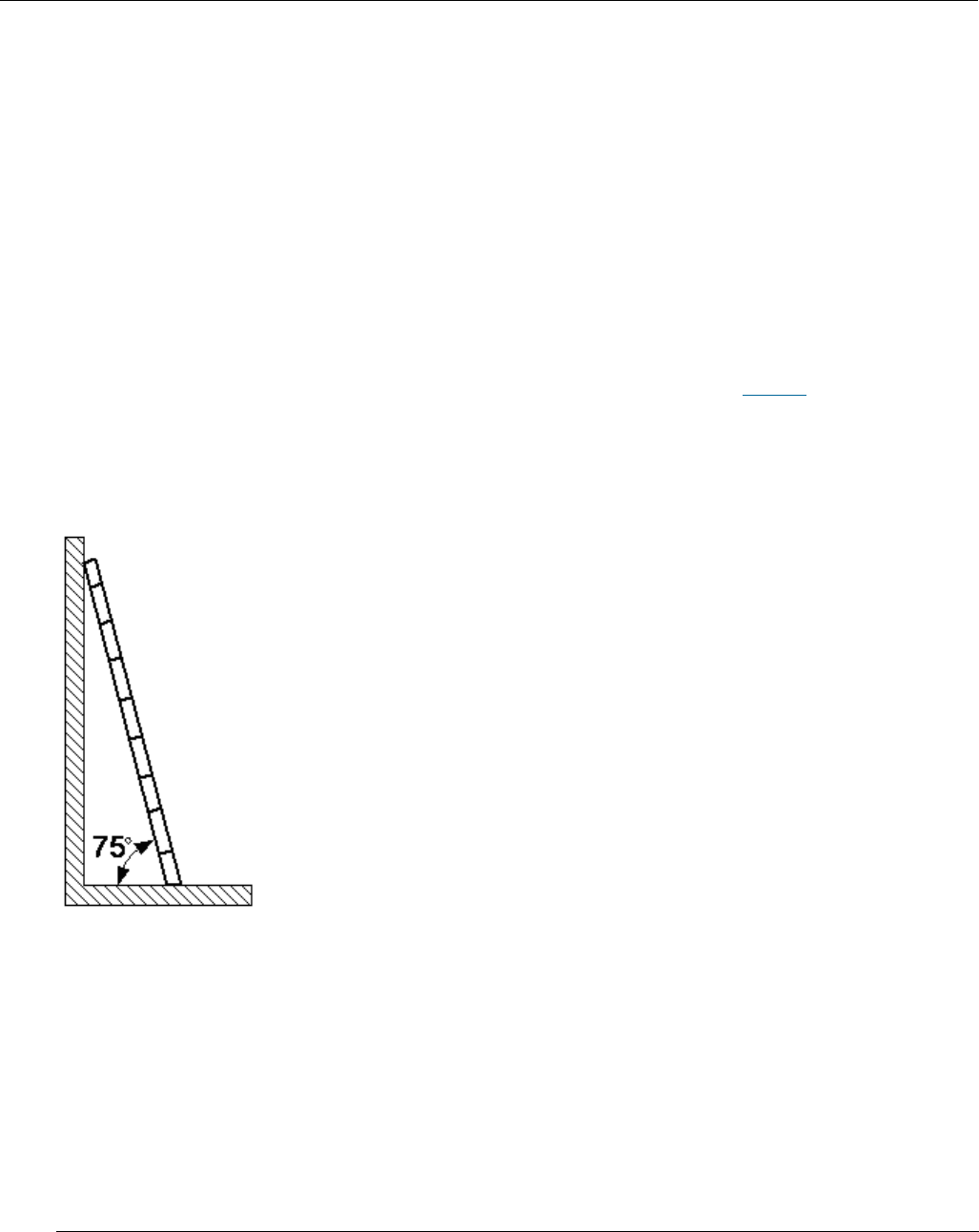
Placing Ladders
The recommended gradient of the ladder is 75 degrees. You can measure the
gradient of the ladder with an right angle or your arm. See Figure 1. When using a
ladder, ensure that the wider feet of the ladder are downward, or take
protection measures for the ladder feet to prevent the ladder from sliding.
Ensure that the ladder is placed securely.
Figure 1 Leaning a ladder
Climbing Up a Ladder
When climbing up a ladder, note the following :
Ensure that the center of gravity of your body does not deviate from the
edges of the two long sides.
To minimize the risk of falling, hold your balance on the ladder before any
operation.
Issue 01 (2017-05-10)
Huawei Proprietary and Confidential
Copyright © Huawei Technologies Co., Ltd.
18
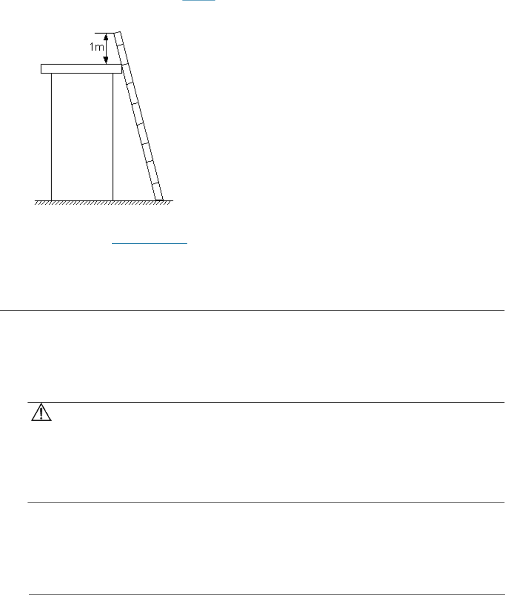
Do not climb higher than the fourth rung of the ladder (counted from up to
down).
If you want to climb up a roof, ensure that the ladder top is at least one meter
higher than the roof. See Figure 2.
Figure 2 Ladder top being one meter higher than the roof
Parent topic: Working at Heights
2.1.5 Mechanical Safety
This section provides safety instructions for drilling holes, handling sharp
objects, operating fans, and carrying heavy objects.
Drilling Holes
NOTICE:
Do not drill the cabinet at will. Drilling holes without complying with the
requirements may affect the electromagnetic shielding performance of the cabinet
and damage the cables inside the cabinet. In addition, if the scraps caused by
drilling enter the cabinet, the printed circuit boards (PCBs) may be short
circuited.
Wear an eye protector when drilling holes. This is to prevent the operator's
eyes from being injured by the splashing metal scraps.
Wear protection gloves when drilling holes.
Issue 01 (2017-05-10)
Huawei Proprietary and Confidential
Copyright © Huawei Technologies Co., Ltd.
19
Sharp Objects
CAUTION:
Before you hold or carry a device, wear protective gloves to avoid getting
injured by sharp edges of the device.
Fans
When replacing the parts near fans, do not insert your fingers or boards into
the operating fans before the fans are switched off and stop running. Otherwise,
the hands of the operator can get hurted.
Carrying Heavy Objects
Wear protection gloves when carrying heavy objects. This is to prevent the
carrier's hands from being hurt.
CAUTION:
The carrier must be prepared for load bearing before carrying heavy objects.
This is to prevent the carrier from being strained or pressed by the heavy
objects.
When you pull a chassis out of the cabinet, pay attention to the unstable or
heavy objects on the cabinet. This is to prevent the heavy objects on the
cabinet top from falling down, which may hurt the operator.
Generally, two persons are needed to carry a chassis. It is prohibited that
only one person carries a heavy chassis. When carrying a chassis, the
carriers should stretch their backs and move stably to avoid being strained.
When moving or lifting a chassis, hold the handles or bottom of the chassis.
Do not hold the handles of the modules installed in the chassis, such as the
power modules, fan modules, and boards.
Parent topic: Health and Safety
2.2 Equipment Safety
This section provides the safety instructions that you must follow when
installing, operating, and maintaining Huawei devices.

Issue 01 (2017-05-10)
Huawei Proprietary and Confidential
Copyright © Huawei Technologies Co., Ltd.
20
General Instructions
This section provides the general instructions for the installation, operation,
and maintenance of Huawei devices.
Electrical Safety
This section provides safety instructions for high voltage, high leakage current,
power cables, fuses, and electrostatic discharge (ESD).
Inflammable Environment
This section provides safety instructions for operations in an air environment
where devices are operating.
Battery
This section provides safety instructions for operations of storage batteries
and lithium ion batteries.
Mechanical Safety
This section provides safety instructions for hole drilling and fans.
Others
This section provides safety instructions for installing and removing boards,
binding signal cables, and handling cables at low temperature.
Parent topic: Safety
2.2.1 General Instructions
This section provides the general instructions for the installation, operation,
and maintenance of Huawei devices.
All Safety Instructions
To ensure the safety of humans and the device, follow the marks on the device
and all the safety instructions in this document.
The "CAUTION", "WARNING", and "DANGER" marks in this document are only
supplements to the safety instructions.
Local Laws and Regulations
When operating the device, you must follow the local laws and regulations. The
safety instructions in this document are only supplements to the local laws and
regulations.
Basic Installation Requirements

Issue 01 (2017-05-10)
Huawei Proprietary and Confidential
Copyright © Huawei Technologies Co., Ltd.
21
Only professional or qualified personnel are allowed to install, operate, and
maintain the equipment.
Only qualified and professional personnel are allowed to dismantle security
facilities and troubleshoot the equipment.
Only the personnel certified or authorized by Huawei are allowed to replace
or change the device of the parts or the device (including the software).
The operator must report the faults or errors that may cause safety problems
to the person in charge of the device immediately.
Grounding Requirements
The following requirements only apply to the devices that need to be grounded.
When you install a device, you must ground it first. When you remove a device,
you must remove the ground cable at last.
Damaging grounding conductors is prohibited.
Operating a device before the grounding conductor is installed is prohibited.
Devices must be connected to the grounding earth permanently. Before
operating a device, check the electrical connection of the device and ensure
that the device is properly grounded.
Device Safety
Before operating the device, securely fix the device on the floor or another
stable object, for example, a wall or an installation rack.
Do not block the ventilation openings when the device is in operation.
When installing panels, you must use a proper tool to tighten the screws.
After installing the device, clear the package material from the site where
the device is installed.
Parent topic: Equipment Safety
2.2.2 Electrical Safety
This section provides safety instructions for high voltage, high leakage current,
power cables, fuses, and electrostatic discharge (ESD).
High Voltage
Issue 01 (2017-05-10)
Huawei Proprietary and Confidential
Copyright © Huawei Technologies Co., Ltd.
22
DANGER:
Operating the high voltage power supply incorrectly or irregularly may cause
accidents such as fire or electric shock.
High Electrical Leakage
NOTICE:
Before powering on a device, ground the device. Otherwise, the safety of the
device cannot be ensured.
Power Cables
DANGER:
Installing or removing power cables when the device is on is prohibited. This is
because when the cores of power cables contact conductors, electric arcs or
sparks are generated, which may cause fire.
Before installing or removing the power cable, turn off the power switch.
Before connecting a power cable, check that the label on the power cable is
correct.
Fuses
NOTICE:
To ensure the safety of the device, when the fuse on the device is blown, you
must replace the blown fuse with a fuse of the same type and specification.
ESD
NOTICE:
The Static charge generated on human bodies may damage the electrostatic
sensitive devices (ESSDs) on boards, for example, large-scale integration (LSI)
integrated circuits (ICs).
Human body movement, friction between human bodies and clothes, friction
between shoes and floors, or handling of plastic articles causes static
electromagnetic fields on human bodies. These static electromagnetic fields
cannot be eliminated until the static is discharged.
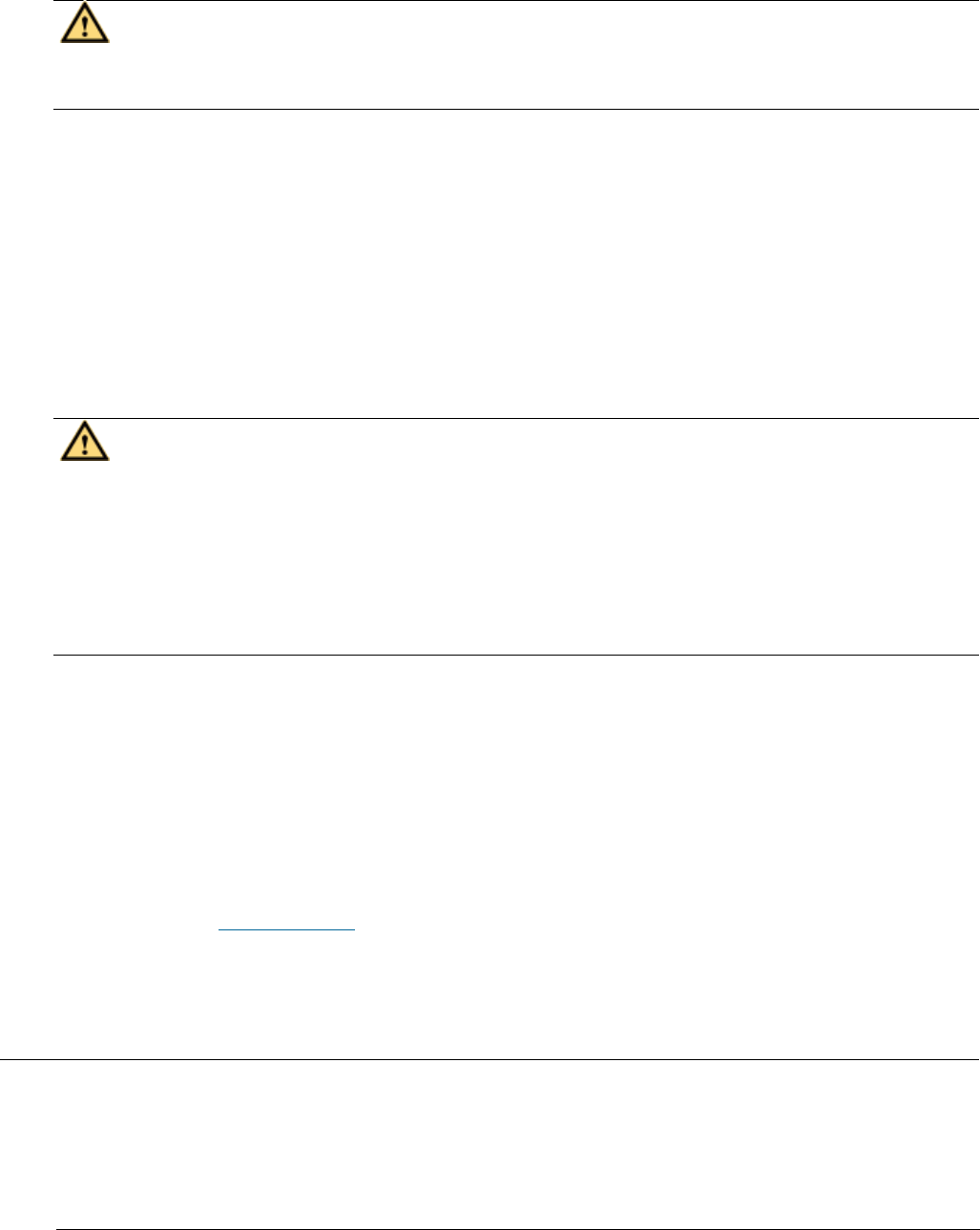
To prevent electrostatic-sensitive components from being damaged by the
static on human bodies, you must wear a well-grounded ESD wrist strap when
Issue 01 (2017-05-10)
Huawei Proprietary and Confidential
Copyright © Huawei Technologies Co., Ltd.
23
touching the device or handling boards or application-specific integrated
circuits (ASICs).
Figure 1 shows how to wear an ESD wrist strap.
Figure 1 Wearing an ESD wrist strap
Table 1 lists the technical specifications of the ESD wrist strap.
Table 1 Technical specifications of the ESD wrist strap
Item
Specification
Grounding resistance of the wrist strap,
expressed in ohms
The resistance should be not less than
0.75 x 10⁶ ohms and not greater than 10 x
106 ohms.
Resistance between the internal surface of
wrist strap and the wrist strap buckle,
expressed in ohms
The resistance should be less than or
equal to 20 x 103 ohms.
Resistance of the connecting cable of the
wrist strap, expressed in ohms
The resistance should be greater than 0.8
x 106 and less than 1.2 x 10⁶ ohms.
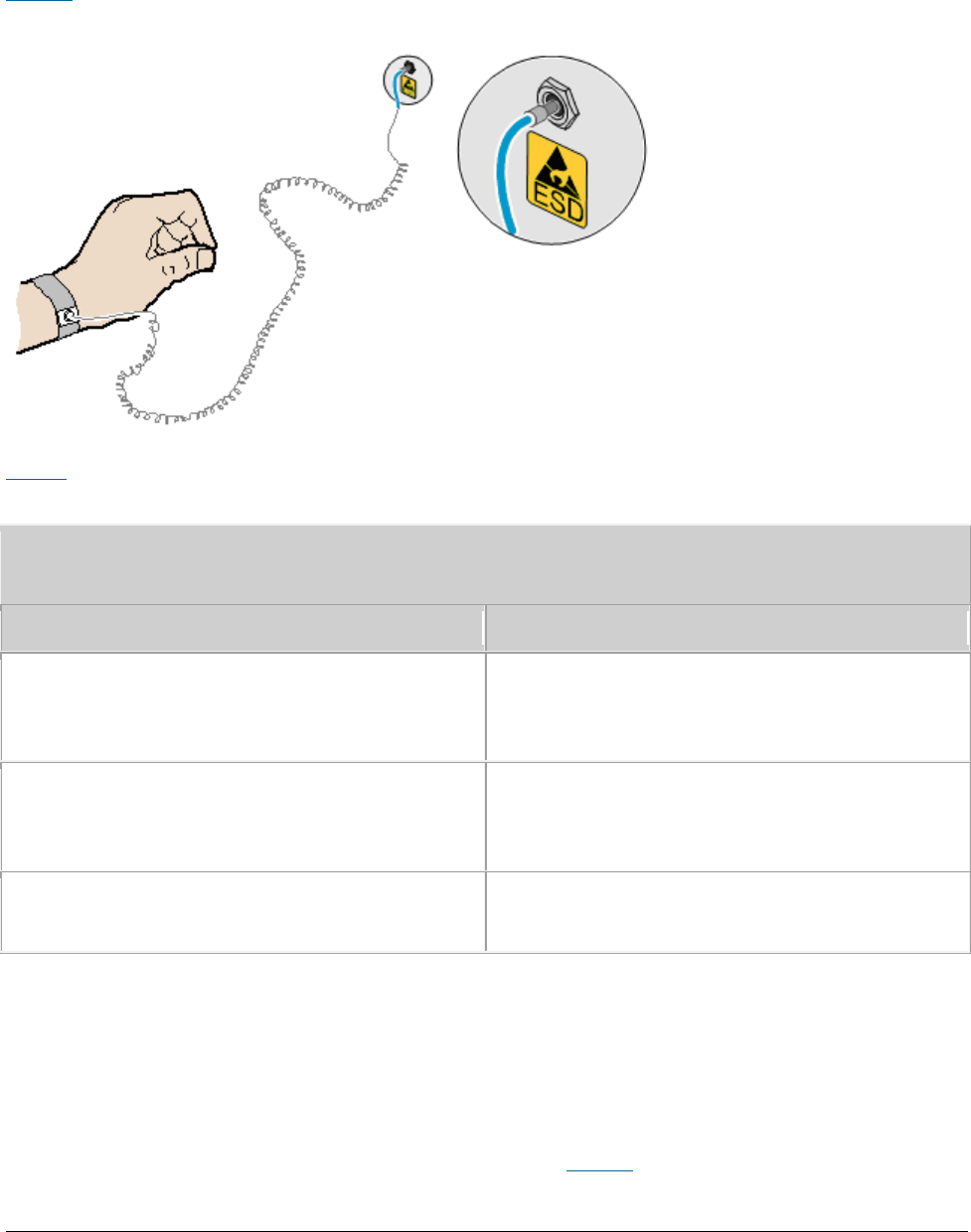
Test the ESD wrist strap periodically to keep it in good and ready to use
condition.
When an ESD wrist strap works normally, the resistance should be within the
range of 1 ohm to 10 ohms.
Measure the resistance between the internal surface of the ESD wrist strap and
the wrist strap buckle using a multimeter. See Figure 2.
Issue 01 (2017-05-10)
Huawei Proprietary and Confidential
Copyright © Huawei Technologies Co., Ltd.
24
Figure 2 Measuring the resistance between the internal surface and the wrist strap
buckle using a multimeter
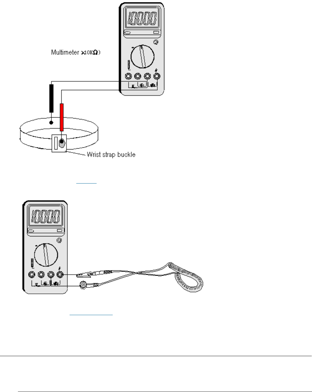
Measure the resistance of the connecting cable of the ESD wrist strap using a
multimeter. See Figure 3.
Figure 3 Measuring the resistance of the connecting cable using a multimeter
Parent topic: Equipment Safety
2.2.3 Inflammable Environment
This section provides safety instructions for operations in an air environment
where devices are operating.
Issue 01 (2017-05-10)
Huawei Proprietary and Confidential
Copyright © Huawei Technologies Co., Ltd.
25
DANGER:
Do not place the device in an environment that has inflammable and explosive air
or gas. Do not perform any operation in this environment.
Operating an electronic device in an environment of flammable air causes a
severe hazard.
Parent topic: Equipment Safety
2.2.4 Battery
This section provides safety instructions for operations of storage batteries
and lithium ion batteries.
Storage Battery
This section provides safety instructions for operations of storage batteries.
Lithium Battery
This section provides safety instructions for operations of lithium ion
batteries.
Parent topic: Equipment Safety
2.2.4.1 Storage Battery
This section provides safety instructions for operations of storage batteries.
Irregular operations of the storage battery cause hazards. When operating the
storage battery, you must avoid short circuit and overflow or loss of the
electrolyte.
Overflow of the electrolyte brings potential hazards to the device because
the overflowing electrolyte erodes the metals and boards and damages the
boards.
Basic Precautions
To ensure safety, note the following points before installing or maintaining the
storage battery:
Issue 01 (2017-05-10)
Huawei Proprietary and Confidential
Copyright © Huawei Technologies Co., Ltd.
26
Use special insulation tools.
When handling the storage battery, ensure that its electrodes are upward.
Leaning or reversing the storage battery is prohibited.
Before installing or maintaining the storage battery, ensure that the storage
battery is disconnected from the power supply that charges the storage
battery.
Short Circuit
CAUTION:
Battery short circuit may cause human injuries. Although the voltage of ordinary
batteries is low, the instantaneous high current caused by the short circuit
releases a great deal of energy.
Avoid short circuit of batteries caused by metal objects. If possible,
disconnect working batteries before the other operations.
Hazardous Gas
NOTICE:
Using unsealed lead acid storage batteries is prohibited. Lead acid storage
batteries must be placed horizontally and stably to prevent the batteries from
releasing flammable gas, which may cause fire or erode the device.
Working lead acid storage batteries release flammable gas. Therefore,
ventilation and fireproofing measures must be taken at the sites where lead acid
storage batteries are placed.
Battery Temperature
NOTICE:
If a battery overheats, the battery may be deformed or damaged, and the
electrolyte may overflow.
When the temperature of the battery is higher than 60°C (140°F), you need to
check whether the electrolyte overflows. If the electrolyte overflows, you can
use Battery Leakage to absorb and counteract the leaking electrolyte.
Battery Leakage
CAUTION:
Issue 01 (2017-05-10)
Huawei Proprietary and Confidential
Copyright © Huawei Technologies Co., Ltd.
27
When the electrolyte overflows, absorb and counteract the electrolyte
immediately.When moving or handling a battery whose electrolyte leaks, note that
the leaking electrolyte may hurt human bodies.
When you find the electrolyte leaks, Select a substance to absorb and counteract
the leaking electrolyte according to the instructions of the battery
manufacturer.
Parent topic: Battery
2.2.4.2 Lithium Battery
This section provides safety instructions for operations of lithium ion
batteries.
CAUTION:
Replacing a lithium ion battery with a lithium ion battery of another model may
cause explosion.
You can replace a lithium ion battery only with a lithium ion battery of a
model recommended by the manufacturer.
Exhausted lithium ion batteries must be disposed of according to the
instructions.
Do not throw lithium ion batteries into fire.
Parent topic: Battery
2.2.5 Mechanical Safety
This section provides safety instructions for hole drilling and fans.
Drilling Holes
NOTICE:
Do not drill the cabinet at will. Drilling holes without complying with the
requirements may affect the electromagnetic shielding performance of the cabinet
Issue 01 (2017-05-10)
Huawei Proprietary and Confidential
Copyright © Huawei Technologies Co., Ltd.
28
and damage the cables inside the cabinet. In addition, if the scraps caused by
drilling enter the cabinet, the printed circuit boards (PCBs) may be short
circuited.
Before drilling holes in a cabinet, move the cables inside the cabinet away
from the drilling positions.
Prevent metal scraps from falling into the cabinet. After drilling holes,
clear the metal scraps.
Fans
When replacing parts, place the objects such as the parts, screws, and tools
properly. This is to prevent them from falling into the operating fans, which
damages the fans or device.
Parent topic: Equipment Safety
2.2.6 Others
This section provides safety instructions for installing and removing boards,
binding signal cables, and handling cables at low temperature.
Installing and Removing Boards
NOTICE:
Before installing a board, you need to wear an electrostatic discharge (ESD)
wrist strap and ESD gloves. When installing the board, use proper force to
prevent the pins on the backplane from being leaned.
To ensure all the boards are running properly, Installing and Removing Boards
must fulfill the following requirements:
Install the board along the guide rails.
Prevent the surface of a board from contacting the surface of another board.
This is to prevent the boards from being short circuited or scratched.
To prevent the electrostatic sensitive devices (ESSDs) from being damaged by
the static charge on the human body, do not touch the circuits, components,
connectors, or cable connection slots on the boards.
Binding Signal Cables
Issue 01 (2017-05-10)
Huawei Proprietary and Confidential
Copyright © Huawei Technologies Co., Ltd.
29
NOTICE:
Do not bind signal cables with high current cables or high voltage cables.
Laying Out Cables
When the temperature is very low, violent strike or vibration may disturb the
plastic coats of cables. To ensure safety, fulfill the following requirements:
Cables can be laid or installed only when the temperature is higher than 0°C
(32°F).
Before laying out cables which have been stored in a temperature lower than
0°C (32°F), move the cables to an environment of the ambient temperature
and store them in the ambient temperature for at least 24 hours.
Handle cables with caution, especially in a low temperature. Irregular
operations, such as pushing cables down from the vehicle, are prohibited.
Parent topic: Equipment Safety
3 Description
eAN3810A Product Description
eAN3810A Hardware Description
eAN3810A Security Management Description
3.1 eAN3810A Product Description
Overview
This document describes the eAN3810A in term of product features, network
position and functions, logical structure, transport network topologies,
operation and maintenance, technical specifications, and reliability. It aims to
help user better understand the eAN3810A.
Product Version
NOTE:

Issue 01 (2017-05-10)
Huawei Proprietary and Confidential
Copyright © Huawei Technologies Co., Ltd.
30
Unless otherwise stated, "eNodeB", "Pico", "eAN", and "AirNode" in this document refer to the
3810 series AirNode.
The 3810 series AirNode is a base station that provides communications services
in Huawei OneAir solution. The following table lists the product name and
product version related to the 3810 series AirNode.
Product Name
Product Version
eAN3810A
V100R001C00
Intended Audience
This document is intended for:
Network planners
System engineers
Organization
Introduction
Architecture
Operation and Maintenance
Technical Specifications
Parent topic: Description
3.1.1 Introduction
Positioning
Benefits
Parent topic: eAN3810A Product Description
3.1.1.1 Positioning

Issue 01 (2017-05-10)
Huawei Proprietary and Confidential
Copyright © Huawei Technologies Co., Ltd.
31
OneAir is an Huawei wireless communications solution launched based on the
principle of "innovation based on customer requirements." This solution uses
technologies over the LTE air interface on the unlicensed frequency bands to
meet the requirements of enterprise data communications.
The eAN3810A is a base station that provides communications services in Huawei
OneAir solution. This new product is developed based on unlicensed frequency
bands, integrates multi-functional modules, combines various technologies, and
complies with the development trend of the mobile network.
Parent topic: Introduction
3.1.1.2 Benefits
The eAN3810A is compact and light, which enables plug-and-play deployment and
offers self-configuration features without the need for shelter or equipment
room facilities, significantly simplifying site acquisition and network
deployment. The eAN3810A provides a fast and convenient solution for enterprise
customers.
Compact Structure and Fast Network Deployment
The eAN3810A has a highly integrated design with small size and light weight. It
is easy to install and maintain. The eAN3810A can be installed on a wall or pole
instead of in an equipment room.
Its flexible installation locations and small size facilitate site acquisition,
increasing network flexibility and saving network deployment costs and time.
Large Capacity and Wide Coverage
The eAN3810A has a large capacity. The LTE technologies and coverage enhancement
significantly improve the coverage, providing customers with stable and reliable
connections.
Comprehensive and Cost-Effective Transmission Modes
The eAN3810A supports all-IP transmission and can be deployed in star topologies.
Parent topic: Introduction
Issue 01 (2017-05-10)
Huawei Proprietary and Confidential
Copyright © Huawei Technologies Co., Ltd.
32
3.1.2 Architecture
Network Architecture and Topologies
This section describes the network architecture and topologies for AirNode.
Hardware Appearance
This section describes the appearance of a eAN3810A.
Logical Structure
The eAN3810A consists of a transmission and interface unit, main control unit,
baseband processing unit, clock unit, and radio frequency (RF) unit.
Parent topic: eAN3810A Product Description
3.1.2.1 Network Architecture and Topologies
This section describes the network architecture and topologies for AirNode.
Network Architecture
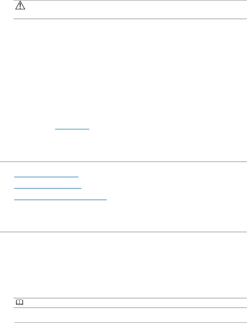
Figure 1 shows the position of a AirNode on a OneAir solution network.
Figure 1 OneAir solution network
UE: User Equipment
eAN: Enterprise AirNode
OSS: Operations Support System
eSE: Enterprise Service Engine
As shown in Figure 1, the AirNode is the network access equipment of the OneAir
network and one more multiple AirNode compose an E-UTRAN. The AirNode
communicates with UEs over the Uu interface and communicates with the eSE and
OSS over the PoE interface.
Issue 01 (2017-05-10)
Huawei Proprietary and Confidential
Copyright © Huawei Technologies Co., Ltd.
33
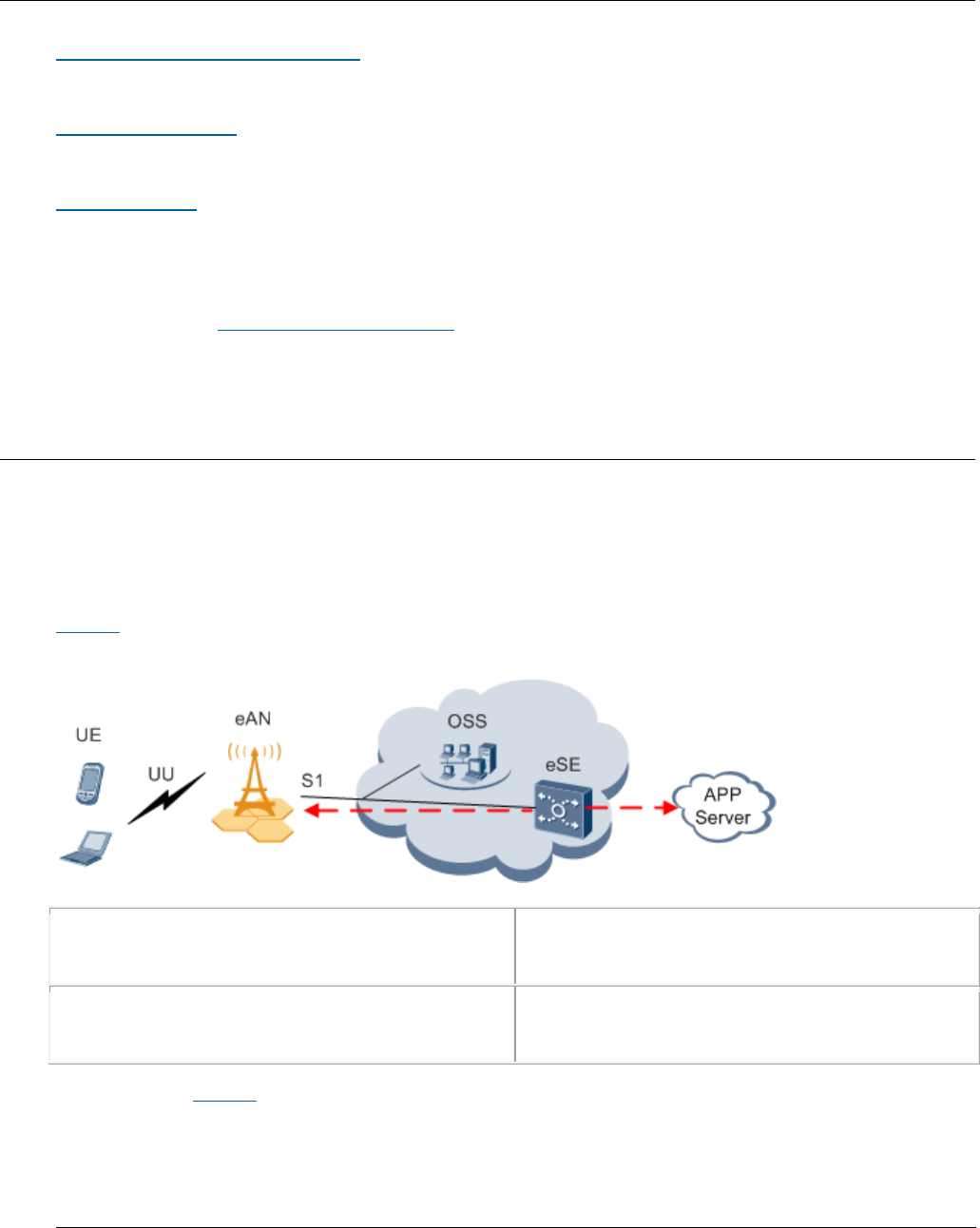
Topologies
AirNode support the star topology over IP networking. Figure 2 shows the star
topology.
Figure 2 Star topology
Advantages:
AirNode are directly connected to the eSE. The star topology decreases
networking complexity and facilitates engineering implementation, maintenance,
and capacity expansion.
AirNode directly exchange data with the eSE. Signals travel through only a
few nodes, and therefore data transmission reliability is high.
Disadvantage: Compared with other topologies, the star topology requires more
transmission resources.
Parent topic: Architecture
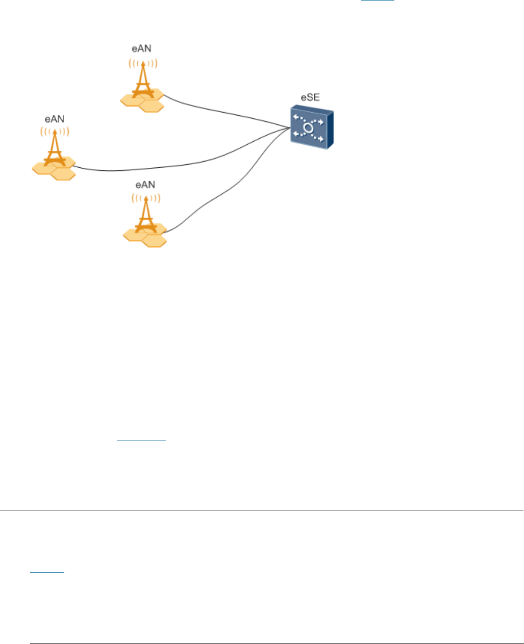
3.1.2.2 Hardware Appearance
This section describes the appearance of a eAN3810A.
Figure 1 shows the appearance of a eAN3810A.
Issue 01 (2017-05-10)
Huawei Proprietary and Confidential
Copyright © Huawei Technologies Co., Ltd.
34
Figure 1 Appearance of a eAN3810A
Parent topic: Architecture
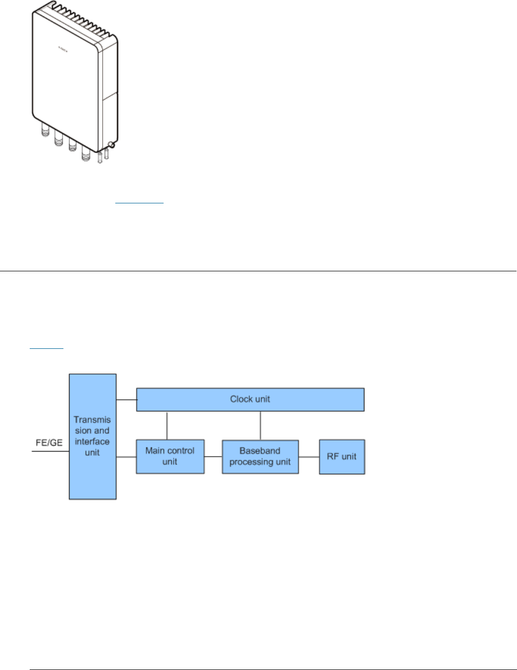
3.1.2.3 Logical Structure
The eAN3810A consists of a transmission and interface unit, main control unit,
baseband processing unit, clock unit, and radio frequency (RF) unit.
Figure 1 shows the logical structure of the eAN3810A.
Figure 1 Logical structure of the eAN3810A
Descriptions of the eAN3810A functional units are as follows:
Transmission and interface unit: forwards data between a transport network
and the base station. This unit provides physical ports between the base
station and the transport network, and the user-plane interface between the
base station and other NEs.
Main control unit: controls and manages resources in the base station. This
unit provides the management-plane interface between the base station and the
network management, the control-plane interface between the base station and
other NEs.

Issue 01 (2017-05-10)
Huawei Proprietary and Confidential
Copyright © Huawei Technologies Co., Ltd.
35
Clock unit: provides clock synchronization. Provides the interface between
the base station and the external clock source,The clock synchronization
modes supported by the AirNode are RGPS, IEEE 1588v2 (Only frequency
synchronization is supported) and synchronous Ethernet.
Baseband processing unit: processes uplink and downlink baseband data.
RF unit: Complete the wireless signal transceiver function. Provides the
interface between the base station and the antenna system.
Parent topic: Architecture
3.1.3 Operation and Maintenance
O&M Modes
This section describes the O&M modes and O&M system for the AirNode.
O&M Functions
The O&M functions include configuration management, fault management,
performance management, security management, software management, deployment
management, device management, and inventory management.
Parent topic: eAN3810A Product Description
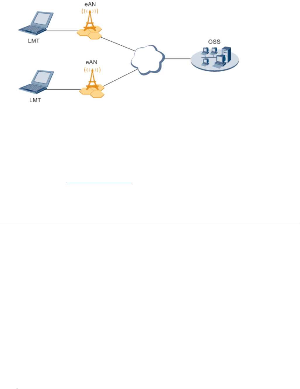
3.1.3.1 O&M Modes
This section describes the O&M modes and O&M system for the AirNode.
The AirNode supports the following O&M modes:
Remote maintenance on the U2000 at the OMC
Local maintenance on the LMT
Figure 1 shows the O&M system for the AirNode.
Issue 01 (2017-05-10)
Huawei Proprietary and Confidential
Copyright © Huawei Technologies Co., Ltd.
36
Figure 1 O&M system for the AirNode
An O&M system of the AirNode includes the following elements:
LMT: maintains a single AirNode locally.
OSS: maintains multiple AirNode remotely.
eAN: AirNode, refers to the target of O&M operations.
Parent topic: Operation and Maintenance
3.1.3.2 O&M Functions
The O&M functions include configuration management, fault management,
performance management, security management, software management, deployment
management, device management, and inventory management.
Configuration Management
Configuration management allows operators to configure network resources by
using configuration data in network devices, thereby controlling the running
status of network devices. Configuration management is required on the entire
network O&M cycle.
During network deployment, configuration management allows operators to
initialize configuration data, and install and set up network devices.
AirNode support regional deployment and site deployment.
During network adjustment, optimization, or routine O&M, configuration
management allows operators to configure parameters for new features, and
modify parameter settings for scenarios such as network capacity expansion,

Issue 01 (2017-05-10)
Huawei Proprietary and Confidential
Copyright © Huawei Technologies Co., Ltd.
37
transmission adjustment, and wireless network performance optimization.
Configuration management also allows operators to monitor and modify network
parameters.
Fault Management
Fault management involves fault detection, fault isolation, self-healing, alarm
reporting, and alarm correlation. The AirNode can manage faults in hardware,
environment, software, transmission, cells, and services.
Users view faults on the device panel and perform simple operations.
Fault isolation prevents faults from affecting the operational continuity of
the AirNode. Self-healing minimizes the impact of faults on services by
lowering performance or reestablishing cells.
Alarm correlation enables the AirNode to report only the root fault and the
ultimate impact on services. Alarm correlation helps engineers quickly
pinpoint the root fault, analyze severity, and take measures to rectify the
root fault instead of rectifying the associated faults.
Performance Management
Performance management involves periodic performance measurement on the AirNode
and the collection, storage, and reporting of measurement results.
Tracing Management
Tracing management facilitates routine maintenance, commissioning, and
troubleshooting by tracing internal messages as well as messages related to
interfaces, signaling links, and UEs.
Signaling messages are traced either on the OSS or on the LMT.
Security Management
Security management implements user authentication and access control. It
includes user account management, rights management, login management, identity
authentication, and operation authentication.
Security control on the transmission channels between the AirNode and the OSS
supports Secure Socket Layer (SSL), Public Key Infrastructure (PKI).
Security management provides network- and user-specific security services. It
provides the following functions:
Encryption: encrypts important user information.
Authentication: manages and authenticates user accounts.

Issue 01 (2017-05-10)
Huawei Proprietary and Confidential
Copyright © Huawei Technologies Co., Ltd.
38
Access control: controls user operations.
Security protocol: support SSL security protocol.
Software Management
Software management involves the following functions:
Software version management: Software versions can be queried, and restored.
Software version upgrade: AirNode can be remotely upgraded in batches. With
the one-click remote upgrade wizard provided by the OSS,
Patch management involves patch query, download, loading, activation,
deactivation, rollback, confirmation, and removal.
Inventory Management
Inventory management involves the collection and reporting of inventory
information about the AirNode. With inventory management, you can manage network
equipment assets at the OMC.
Parent topic: Operation and Maintenance
3.1.4 Technical Specifications
RF Specifications
Capacity Specifications
Output Power
Equipment Specifications
Environment Specifications
Protocols and Standards Compliance
Parent topic: eAN3810A Product Description
3.1.4.1 RF Specifications
Issue 01 (2017-05-10)
Huawei Proprietary and Confidential
Copyright © Huawei Technologies Co., Ltd.
39
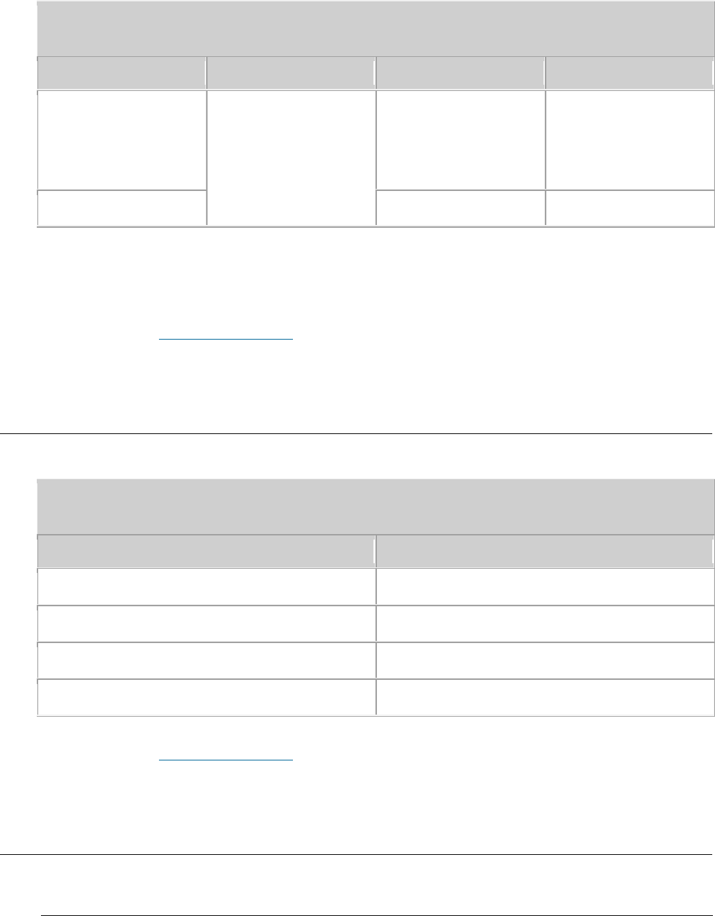
Table 1 RF specifications
Frequency Band
RAT
Frequency RangeS
Receiving Sensitivity
5 GHz
LTE(TDD)
5.470 GHz to 5.725
GHz
5.725 GHz to 5.850
GHz
-100 dBm
2.4 GHz
2.400GHz to 2.483GHz
-100 dBm
Note: This certification only test 5725 ~ 5850mhz band, the rest of the band is
shielded by software.
Parent topic: Technical Specifications
3.1.4.2 Capacity Specifications
Table 1 Capacity specifications
Item
Specifications
Maximum number of cells of a single site
2
Supported cell bandwidth
20 MHz
Maximum number of users
192 RRC connected UEs per cell
Maximum throughput
SA0(1:3) DL:50Mbps; UL:40Mbps
Parent topic: Technical Specifications
3.1.4.3 Output Power
Issue 01 (2017-05-10)
Huawei Proprietary and Confidential
Copyright © Huawei Technologies Co., Ltd.
40
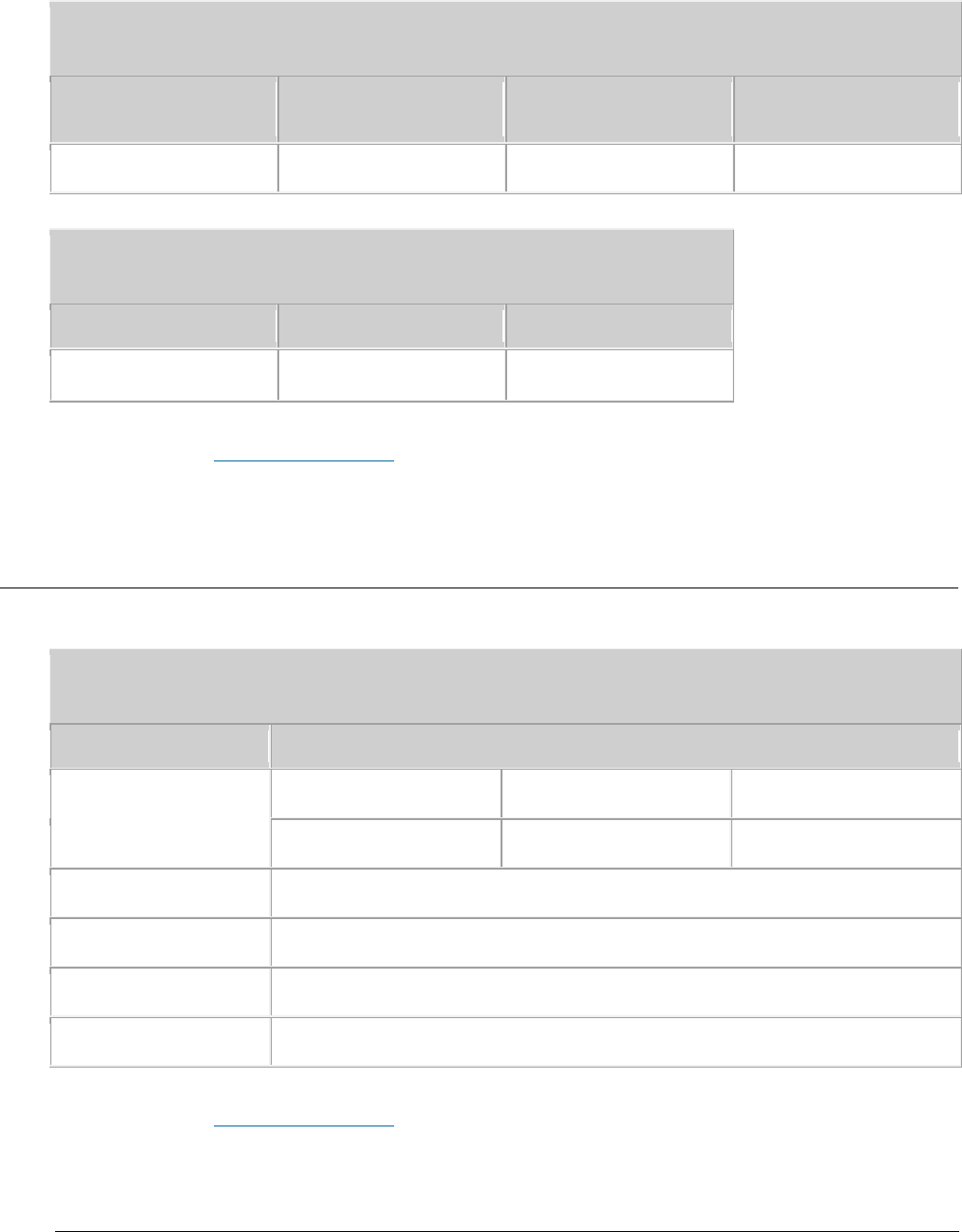
Table 1 3.3 Output power
Number of Cells
Number of TX and RX
Channels Per Cell
Frequency Band
Maximum TOC Power
of single Channel
2
2T2R
5 GHz
≤ 21 dBm (125 mW)
Table 1 3.4 External antenna specifications
Frequency Band
Gain
Directionality
5 GHz
7dBi
Omnidirectional
Parent topic: Technical Specifications
3.1.4.4 Equipment Specifications
Table 1 Equipment specifications
Item
Specifications
Dimensions
Height (mm)
Width (mm)
Depth (mm)
290
210
85
Weight
≤ 5.5 kg
Input voltage
PoE power supply: -48 V DC
Transmission port
One FE/GE electrical port
Power consumption
≤ 65 W
Parent topic: Technical Specifications
Issue 01 (2017-05-10)
Huawei Proprietary and Confidential
Copyright © Huawei Technologies Co., Ltd.
41
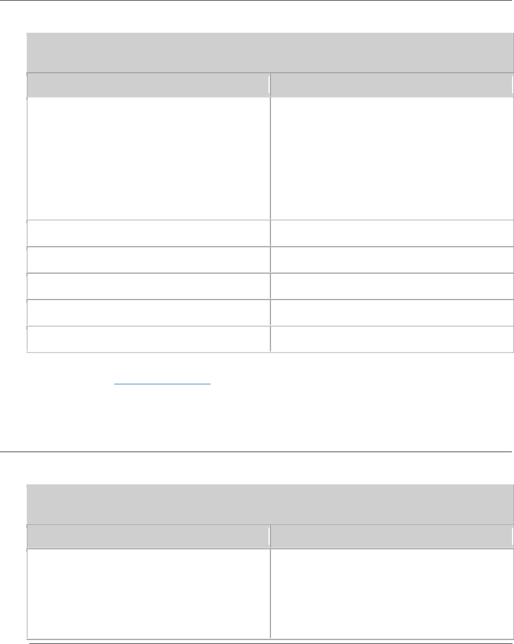
3.1.4.5 Environment Specifications
Table 1 Environment specifications of eAN3810A
Item
Specifications
Operating temperature
-40ºC to +45ºC (with solar radiation)
-40ºC to +50ºC (without solar radiation)
NOTE:
At -40ºC to -20ºC, the AirNode can start up, but its
performance cannot meet requirements. At -20ºC to
+50ºC, the performance of the AirNode meets
requirements.
Storage temperature
-40ºC to +70ºC
Relative humidity
5% RH to 95% RH
Absolute humidity
1 g/m3 to 30 g/m3
Atmospheric pressure
70 kPa to 106 kPa
Protection class
IP65
Parent topic: Technical Specifications
3.1.4.6 Protocols and Standards Compliance
Table 1 Standards compliance
Item
Specifications
EMC
The AirNode meets the electromagnetic
compatibility (EMC) requirements and
complies with the following standards:
GB9254 Class B
IEC 61000-4-2
Issue 01 (2017-05-10)
Huawei Proprietary and Confidential
Copyright © Huawei Technologies Co., Ltd.
42
Table 1 Standards compliance
Item
Specifications
IEC 61000-4-6
Environment protection
RoHS
Surge protection
IEC61000-4-5 surge immunity
Protection rating
YD 5098-2001
IEC 61000-4-5
ETSI EN301 489
ITU-T K.20
Security
IEC60950
Environment
ETSI EN 300 019-2-1
ETSI EN 300 019-2-2
ETSI EN 300 019-2-3
IEC 60068-2
Parent topic: Technical Specifications
3.2 eAN3810A Hardware Description
Overview
This section describes the exterior, ports, indicators and cables of eAN3810A.
Product Version
NOTE:
Unless otherwise stated, "eNodeB", "Pico", "eAN", and "AirNode" in this document refer to the
3810 series AirNode.
The 3810 series AirNode is a base station that provides communications services
in Huawei OneAir solution. The following table lists the product name and
product version related to the 3810 series AirNode.

Issue 01 (2017-05-10)
Huawei Proprietary and Confidential
Copyright © Huawei Technologies Co., Ltd.
43
Product Name
Product Version
eAN3810A
V100R001C00
Intended Audience
This document is intended for:
Installation engineers
Site maintenance engineers
System engineers
Organization
eAN3810A Equipment
This section describes the exterior, ports and indicators of eAN3810A.
Auxiliary Devices
The PSE or Dock supplies power to a eAN3810A through an Ethernet cable in PoE
mode.
Mounting Kits
This section describes the mounting brackets for installing a eAN3810A.
Cables
This section describes eAN3810A cables.
Parent topic: Description
3.2.1 eAN3810A Equipment
This section describes the exterior, ports and indicators of eAN3810A.
eAN3810A Exterior
This section describes the exterior and dimensions of a eAN3810A.
eAN3810A Ports
This section describes ports on the eAN3810A panels. An eAN3810A has a bottom
panel, and cabling cavity panel.
eAN3810A Indicators
This section describes the eAN3810A indicators.
Issue 01 (2017-05-10)
Huawei Proprietary and Confidential
Copyright © Huawei Technologies Co., Ltd.
44
Parent topic: eAN3810A Hardware Description
3.2.1.1 eAN3810A Exterior
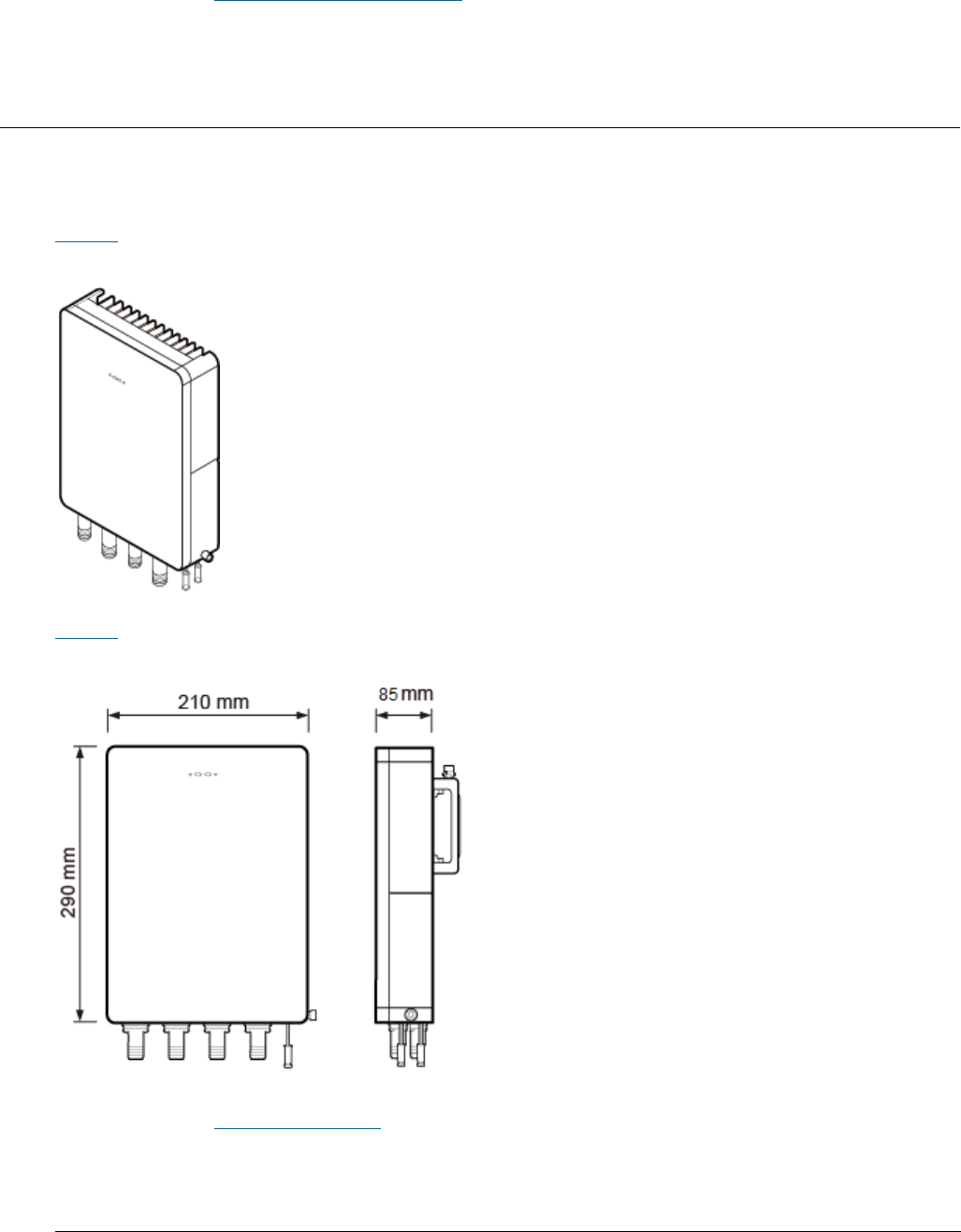
This section describes the exterior and dimensions of a eAN3810A.
Figure 1 shows the exteriors of the eAN3810A.
Figure 1 eAN3810A exterior
Figure 2 shows the dimensions of eAN3810A.
Figure 2 eAN3810A dimensions
Parent topic: eAN3810A Equipment
Issue 01 (2017-05-10)
Huawei Proprietary and Confidential
Copyright © Huawei Technologies Co., Ltd.
45
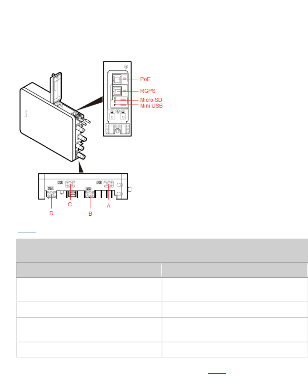
3.2.1.2 eAN3810A Ports
This section describes ports on the eAN3810A panels. An eAN3810A has a bottom
panel, and cabling cavity panel.
Figure 1 shows the ports on the eAN3810A panels.
Figure 1 Ports on the eAN3810A panels
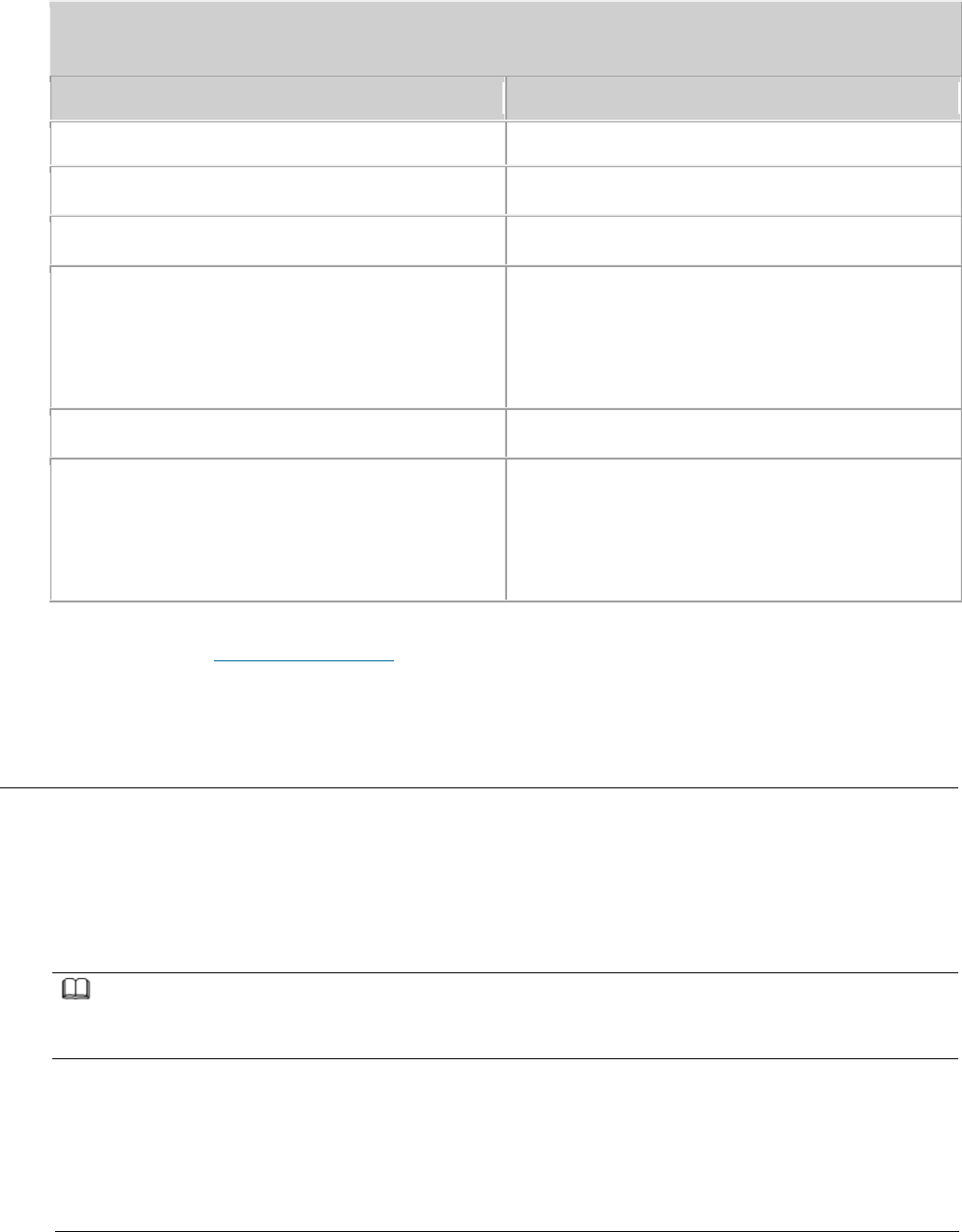
Table 1 describes ports on the eAN3810A cabling cavity panels.
Table 1 Ports on the eAN3810A cabling cavity panels
Port/Slot
Description
PoE
Used for power supply and data
transmission.
RGPS
Used for clock synchronization.
Micro SD
Used for housing a micro SD card. This
slot is used in the case of deployment.
Mini USB
Used for testing a port.
There are four RF ports on an eAN3810A bottom panel, Table 2 lists the TX/RX
frequency band supported by the RF ports.
Issue 01 (2017-05-10)
Huawei Proprietary and Confidential
Copyright © Huawei Technologies Co., Ltd.
46
Table 2 TX/RX frequency band supported by the RF ports
RF ports
TX/RX frequency band
A/B/C/D
5470 MHz to 5850 MHz
Parent topic: eAN3810A Equipment
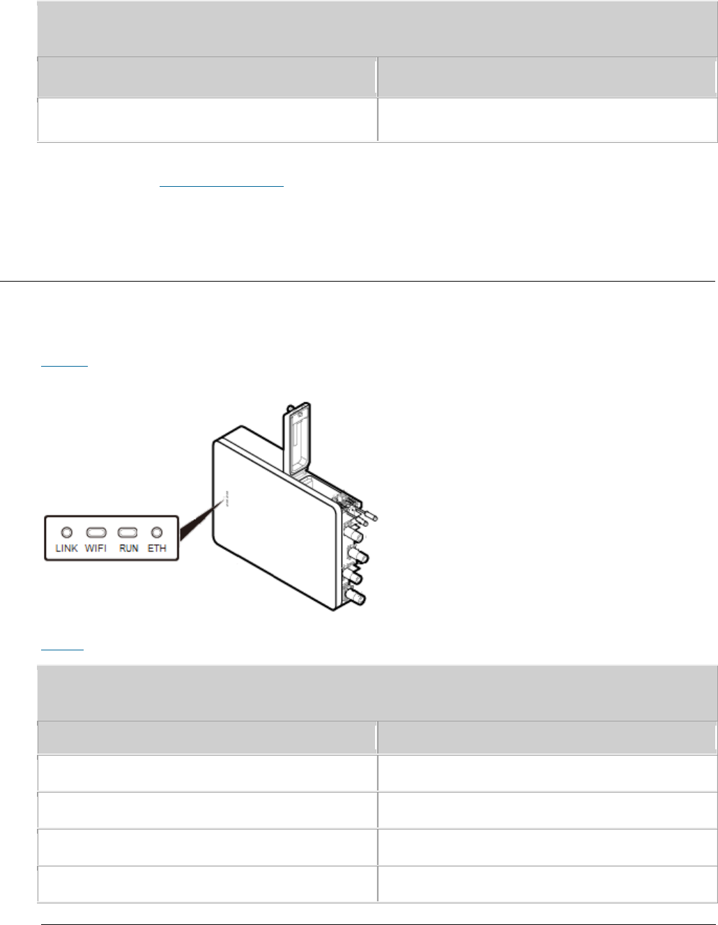
3.2.1.3 eAN3810A Indicators
This section describes the eAN3810A indicators.
Figure 1 shows the position of the eAN3810A indicators.
Figure 1 Position of the eAN3810A indicators
Table 1 describes the eAN3810A indicators.
Table 1 eAN3810A indicators
Indicators
Description
LINK
Link status
WIFI
Wi-Fi processing unit status
RUN
Cellular processing unit status
ETH
ETH status
Issue 01 (2017-05-10)
Huawei Proprietary and Confidential
Copyright © Huawei Technologies Co., Ltd.
47
Parent topic: eAN3810A Equipment
3.2.2 Auxiliary Devices
The PSE or Dock supplies power to a eAN3810A through an Ethernet cable in PoE
mode.
PSE
This section describes the appearance, dimensions, ports, and indicators of the
PSE, and the PSE specifications.
Dock
The Dock supplies power and transfer transmission to a eAN3810A through an
Ethernet cable in PoE mode.
Parent topic: eAN3810A Hardware Description
3.2.2.1 PSE
This section describes the appearance, dimensions, ports, and indicators of the
PSE, and the PSE specifications.
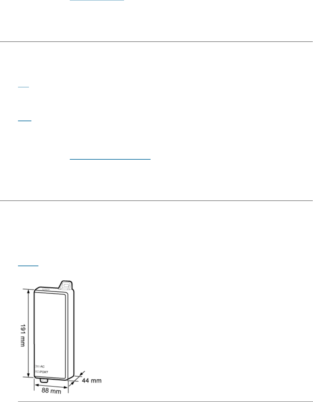
Appearance and Dimensions
Figure 1 shows the appearance and dimensions of the PSE.
Figure 1 Appearance and dimensions of the PSE
Issue 01 (2017-05-10)
Huawei Proprietary and Confidential
Copyright © Huawei Technologies Co., Ltd.
48
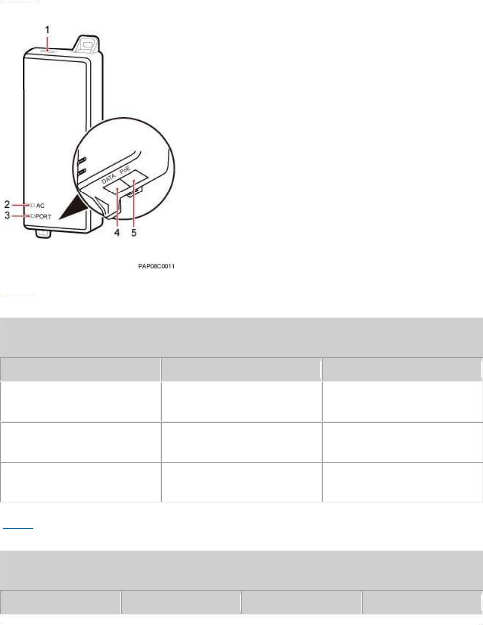
Ports and Indicators
Figure 2 shows the ports and indicators on the PSE.
Figure 2 PSE ports and indicators
Table 1 describes PSE ports.
Table 1 PSE ports
No.
Label
Meaning
1
-
Power supply port used for
PSE power supply
4
DATA
Data input port connecting
to a transmission device
5
PoE
PoE output port connecting
to the eAN3810A
Table 2 describes PSE indicators.
Table 2 PSE indicators
No.
Label
Status
Description
Issue 01 (2017-05-10)
Huawei Proprietary and Confidential
Copyright © Huawei Technologies Co., Ltd.
49
Table 2 PSE indicators
No.
Label
Status
Description
2
AC
Steady green
The power supply is
normal.
Steady off
There is no power
input or the PSE is
faulty.
3
PORT
Steady green
The connection to
the eAN3810A is
normal.
Steady off
The connection to
the eAN3810A is
abnormal or the PSE
is faulty.
Specifications
Table 3 lists PSE specifications.
Table 3 PSE specifications
Item
Specifications
Input voltage
90 V AC to 264 V AC
Input voltage frequency
47 Hz to 63 Hz
Output voltage
56 V DC
Parent topic: Auxiliary Devices
3.2.2.2 Dock
Issue 01 (2017-05-10)
Huawei Proprietary and Confidential
Copyright © Huawei Technologies Co., Ltd.
50
The Dock supplies power and transfer transmission to a eAN3810A through an
Ethernet cable in PoE mode.
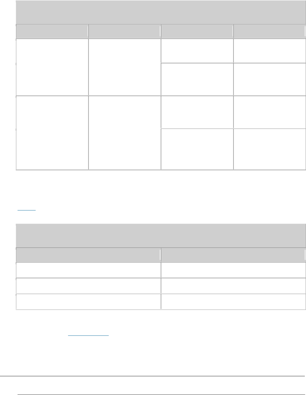
Exterior
The Dock uses the modular structure. Figure 1 shows the exterior and dimensions of
a Dock.
Figure 1 Exterior and dimensions of a Dock
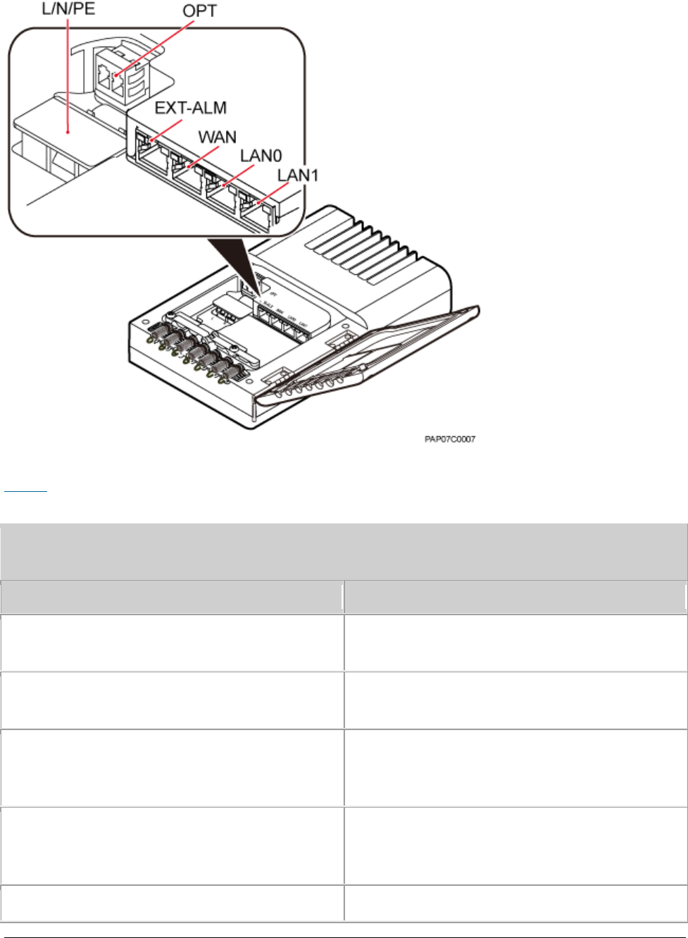
Ports
The ports are inside the Dock. Figure 2 shows the positions of ports on the Dock.
Issue 01 (2017-05-10)
Huawei Proprietary and Confidential
Copyright © Huawei Technologies Co., Ltd.
51
Figure 2 Ports on the Dock
Table 1 describes ports on the Dock.
Table 1 Meanings of ports on the Dock
Label
Description
OPT
FE/GE optical port, used for connecting an
external transmission device.
L/N/PE
AC power port, used for connecting an
external power supply device.
EXT-ALM
Environment monitoring port that provides
four dry contacts, used for connecting
external devices and monitoring alarms.
WAN
P&E transmission and power supply port,
used for connecting an external
transmission device.
LAN0
P&E transmission and power supply port,
Issue 01 (2017-05-10)
Huawei Proprietary and Confidential
Copyright © Huawei Technologies Co., Ltd.
52
Table 1 Meanings of ports on the Dock
Label
Description
used for connecting a BTS3205E. A Dock
supplies power to only one eAN3810A.
LAN1
P&E transmission and power supply port.
Used to connect to commissioning devices,
backhaul devices, or cascaded devices.
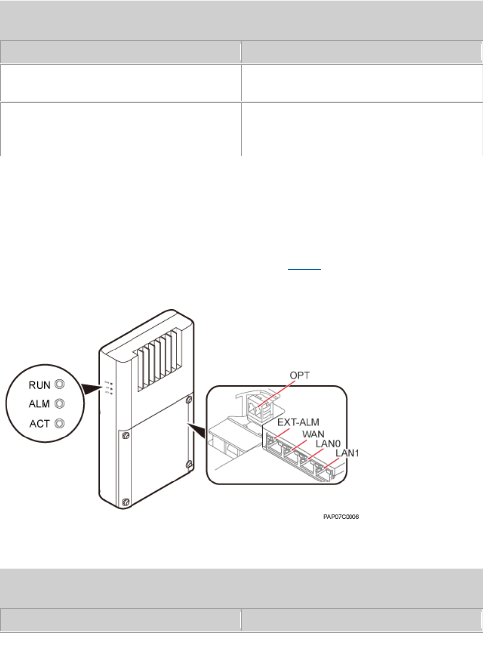
Indicators
The Dock has three external indicators: RUN, ALM, and ACT. The internal RJ45
connector has two indicators showing the connection status and data transmission
status respectively. The internal OPT connector has one indicator showing the
connection status and data transmission status. Figure 3 shows positions of
external indicators on the Dock.
Figure 3 Positions of external indicators on the Dock
Table 2 describes indicators on the Dock external indicators.
Table 2 Dock external indicators
Indicator
Meaning
Issue 01 (2017-05-10)
Huawei Proprietary and Confidential
Copyright © Huawei Technologies Co., Ltd.
53
Table 2 Dock external indicators
Indicator
Meaning
RUN
Operating status
ALM
Alarm status
ACT
Service status
Table 3 describe indicators on the Dock internal indicators.
Table 3 Internal indicators on the Dock
Indicator
Meaning
WAN/LAN0/LAN1
Green indicator: connection status
Orange indicator: Data transmission
OPT
Optical status
Steady green: normal connection, no data
transmission.
Fast blinking green (0.125s interval): in
the process of data transmission.
Off: faulty connection.
Parent topic: Auxiliary Devices
3.2.3 Mounting Kits
This section describes the mounting brackets for installing a eAN3810A.
eAN3810A Mounting Kits
This section describes mounting kits and attachment plates for installing
eAN3810A.
Dock Mounting Kits
This section describes the mounting brackets for installing a Dock.
Issue 01 (2017-05-10)
Huawei Proprietary and Confidential
Copyright © Huawei Technologies Co., Ltd.
54
Parent topic: eAN3810A Hardware Description
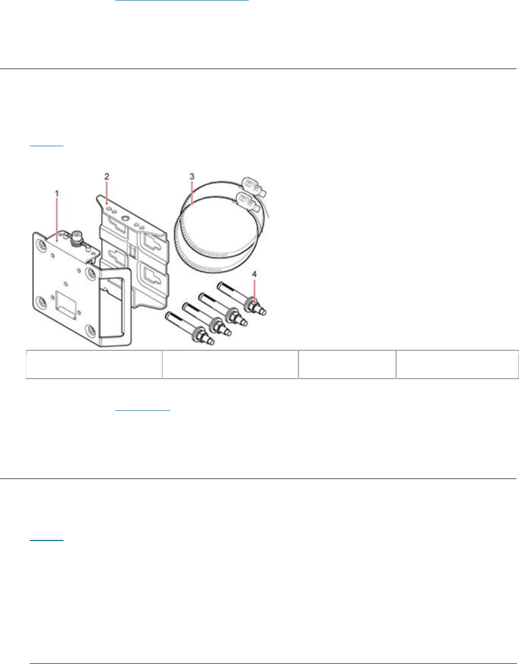
3.2.3.1 eAN3810A Mounting Kits
This section describes mounting kits and attachment plates for installing
eAN3810A.
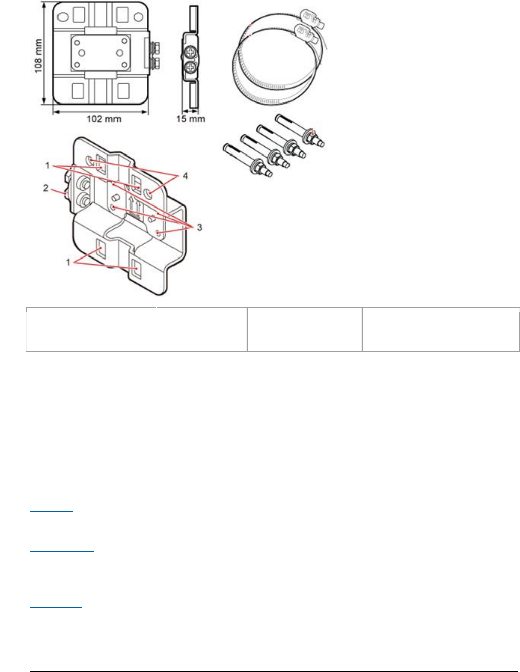
Figure 1 shows a mounting bracket and a attachment plate.
Figure 1 Mounting bracket and common attachment plate for eAN3810A
(1) Attachment plate
(2) Mounting bracket
(3) Hose clamp
(4) Expansion bolt
Parent topic: Mounting Kits
3.2.3.2 Dock Mounting Kits
This section describes the mounting brackets for installing a Dock.
Figure 1 shows a separate Dock mounting bracket.
Issue 01 (2017-05-10)
Huawei Proprietary and Confidential
Copyright © Huawei Technologies Co., Ltd.
55
Figure 1 Appearance of a separate Dock mounting bracket
(1) Hole for routing
a hose clamp
(2) Ground
terminal
(3) Hole for a
captive screw
(4) Hole for inserting
an expansion bolt
Parent topic: Mounting Kits
3.2.4 Cables
This section describes eAN3810A cables.
Cable List
This section describes eAN3810A cable connections.
Ethernet Cable
This section describes the appearance, pin assignment, and installation position
for an Ethernet cable connecting an auxiliary device and an eAN3810A.
PGND cable
An eAN3810A PGND cable connects an eAN3810A and a ground bar, ensuring the
proper grounding of the eAN3810A. The maximum length of an eAN3810A PGND cable
is 8 m (26.25 ft).
Issue 01 (2017-05-10)
Huawei Proprietary and Confidential
Copyright © Huawei Technologies Co., Ltd.
56
RF Jumper
The eAN3810A RF jumper transmits and receives RF signals.
RGPS Signal Cable
The RGPS signal cable between the eAN3710A and RGPS device is used for clock
synchronization. This cable is optional for the eAN3710A.
Parent topic: eAN3810A Hardware Description
3.2.4.1 Cable List
This section describes eAN3810A cable connections.
Table 1 lists eAN3810A cables.
Table 1 List of eAN3810A cables
Cable
One End
The Other End
Connector
Connected to ...
Connector
Connected to ...
Ethernet Cable
RJ45 connector
eAN3810A/PoE
port
RJ45 connector
If connected to
PSE/DATA port
If connected to
Dock/LAN0 port
PGND cable
OT terminal (M6)
Ground terminal
on the eAN3810A
OT terminal (M8)
Ground terminal
on the ground
bar
OT terminal (M6)
Ground terminal
on the Dock
OT terminal (M8)
Ground terminal
on the ground
bar
RF Jumper
Type N male
connector
External antenna
TX/RX RF port on
eAN3810A
Based on the
port model of
the antenna
system.
Antenna system
RGPS Signal Cable
RJ45 connector
eAN3810A/RGPS
port
Round 12-pin
connector
RGPS device
Parent topic: Cables
Issue 01 (2017-05-10)
Huawei Proprietary and Confidential
Copyright © Huawei Technologies Co., Ltd.
57
3.2.4.2 Ethernet Cable
This section describes the appearance, pin assignment, and installation position
for an Ethernet cable connecting an auxiliary device and an eAN3810A.
NOTE:
The Ethernet cable must be of Category 5e (enhanced) or higher. In addition, its cross-
sectional area must be 24 AWG or larger and frame spread rating must be CM or higher.
With the internal PoE module providing power, the maximum length of an Ethernet cable is 100
m.
Both the cable and the RJ45 connectors are delivered, and they must be assembled onsite.
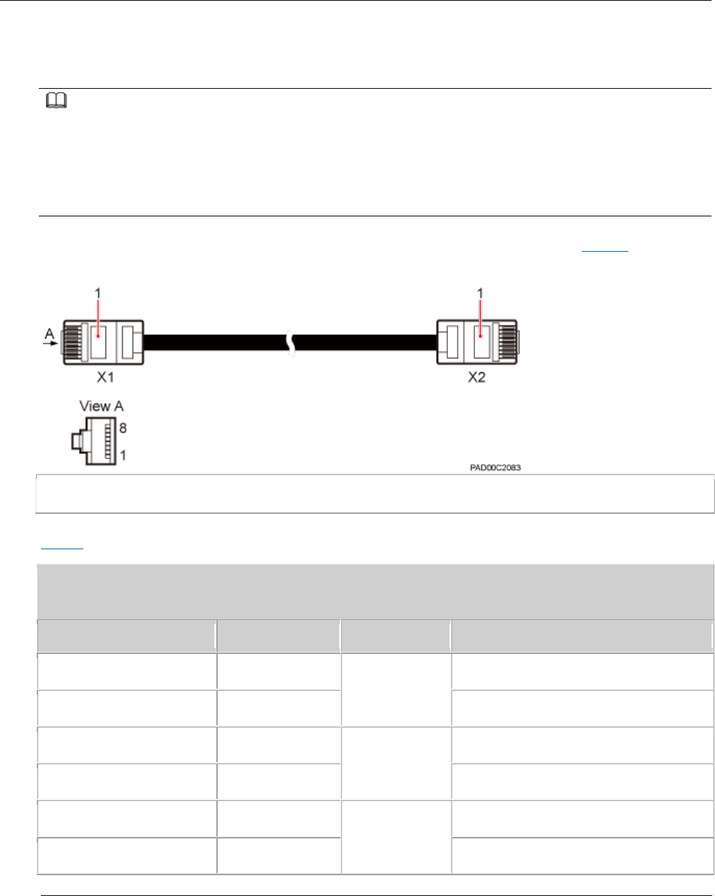
Both ends of the Ethernet cable are RJ45 connectors, as shown in Figure 1.
Figure 1 Ethernet cable exterior
(1) RJ45 connector
Table 1 shows the pin assignment for wires of the Ethernet cable.
Table 1 Pin assignment for wires of the Ethernet cable
Pin of the RJ45 Connector
Color
Core Wire
Pin of the RJ45 Connector
X1.2
Orange
Twisted pair
cable
X2.2
X1.1
White/Orange
X2.1
X1.6
Green
Twisted pair
cable
X2.6
X1.3
White/green
X2.3
X1.4
Blue
Twisted pair
cable
X2.4
X1.5
White/Blue
X2.5
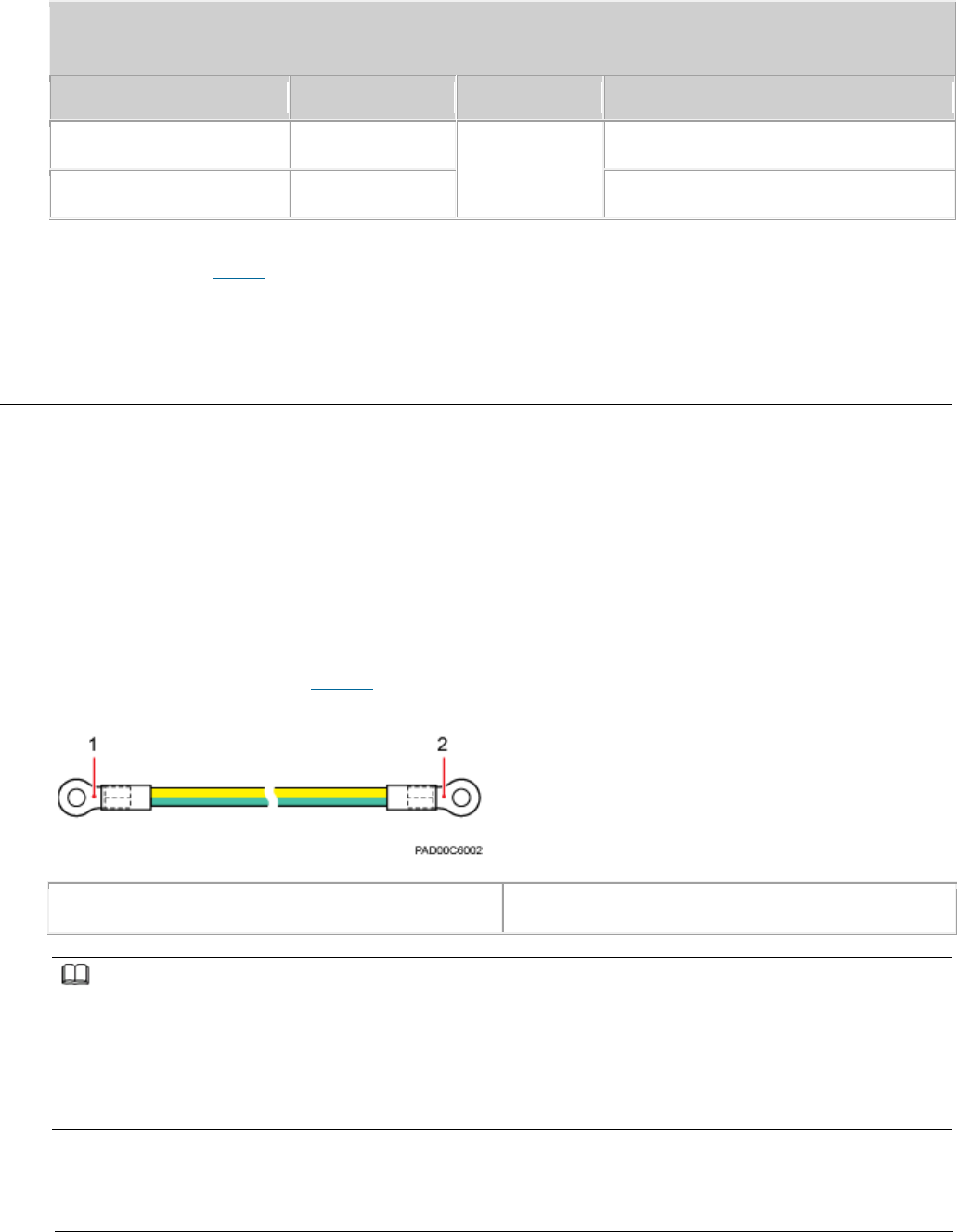
Issue 01 (2017-05-10)
Huawei Proprietary and Confidential
Copyright © Huawei Technologies Co., Ltd.
58
Table 1 Pin assignment for wires of the Ethernet cable
Pin of the RJ45 Connector
Color
Core Wire
Pin of the RJ45 Connector
X1.8
Brown
Twisted pair
cable
X2.8
X1.7
White/brown
X2.7
Parent topic: Cables
3.2.4.3 PGND cable
An eAN3810A PGND cable connects an eAN3810A and a ground bar, ensuring the
proper grounding of the eAN3810A. The maximum length of an eAN3810A PGND cable
is 8 m (26.25 ft).
Exterior
The yellow and green or green PGND cable is a single cable. The cross-sectional
area of the PGND cable is 6 mm2 (0.009 in.2). Both ends of the cable are OT
terminals, as shown in Figure 1.
Figure 1 Exterior of a PGND cable
(1) OT terminal (M6)
(2) OT terminal (M8)
NOTE:
If the PGND cable is provided by the customer, a copper-core cable with a minimum cross-
sectional area of 6 mm2 (0.009 in.2) or 10 AWG is recommended.
The OT terminals at both ends of the PGND cable are assembled at the site.
The M6 OT terminal has the default size. You can replace it with another OT terminal of the
expected size based on the site requirement.
Installation Position
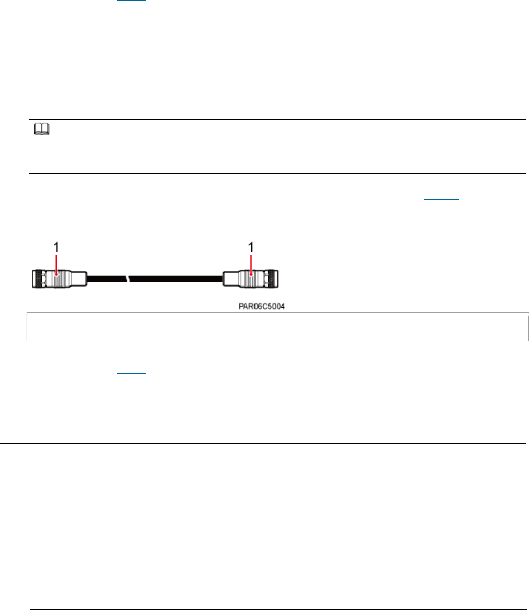
Issue 01 (2017-05-10)
Huawei Proprietary and Confidential
Copyright © Huawei Technologies Co., Ltd.
59
The M6 OT terminal of the PGND cable is connected to the ground screw on the
eAN3810A, and the M8 OT terminal of the PGND cable is connected to the ground
bar at the site.
Parent topic: Cables
3.2.4.4 RF Jumper
The eAN3810A RF jumper transmits and receives RF signals.
NOTE:
If the customer prepares the RF jumper, the length of the RF jumper should be as short as
possible and not exceed 2 m (6.56 ft.).
Both end of the outdoor RF jumper is the type N male connector. Figure 1 shows the
RF jumper.
Figure 1 RF jumper
(1) Type N male connector
Parent topic: Cables
3.2.4.5 RGPS Signal Cable
The RGPS signal cable between the eAN3710A and RGPS device is used for clock
synchronization. This cable is optional for the eAN3710A.
An RGPS signal cable has an RJ45 connector at one end and a round 12-pin
connector at the other end, as shown in Figure 1.
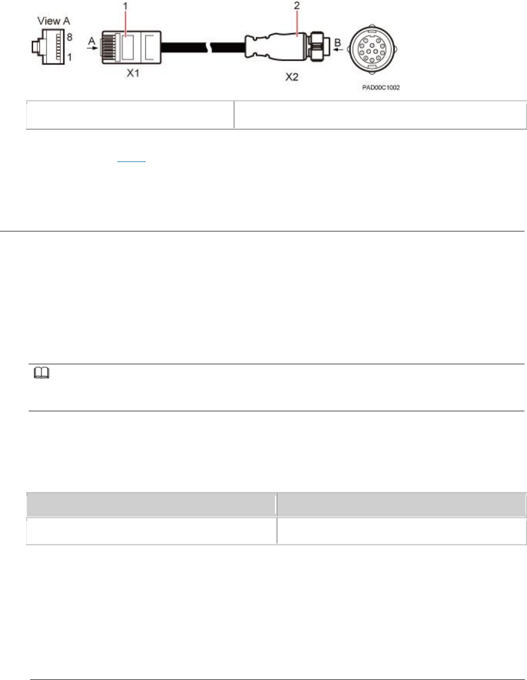
Issue 01 (2017-05-10)
Huawei Proprietary and Confidential
Copyright © Huawei Technologies Co., Ltd.
60
Figure 1 Appearance of an RGPS signal cable
(1) RJ45 connector
(2) Round 12-pin connector
Parent topic: Cables
3.3 eAN3810A Security Management Description
Overview
This document presents an overview of Huawei AirNode security solutions,
including equipment security features, operation and maintenance (O&M) security
features, transmission security features, and radio security features.
Product Version
NOTE:
Unless otherwise stated, "eNodeB", "Pico", "eAN", and "AirNode" in this document refer to the
3810 series AirNode.
The 3810 series AirNode is a base station that provides communications services
in Huawei OneAir solution. The following table lists the product name and
product version related to the 3810 series AirNode.
Product Name
Product Version
eAN3810A
V100R001C00
Intended Audience
This document is intended for:
Network planners
System engineers

Issue 01 (2017-05-10)
Huawei Proprietary and Confidential
Copyright © Huawei Technologies Co., Ltd.
61
Organization
Security Overview
Transmission Security
OM Security
Equipment Security
Reference Information
Parent topic: Description
3.3.2 Transmission Security
Transmission Security Overview
DTLS
IPsec
PKI
SSL
Radio Security
Parent topic: eAN3810A Security Management Description
3.3.5 Reference Information
User Name and Default Password
Parent topic: eAN3810A Security Management Description
3.3.5.1 User Name and Default Password
Table 1 describes the user name and default password in the eAN3810A system.
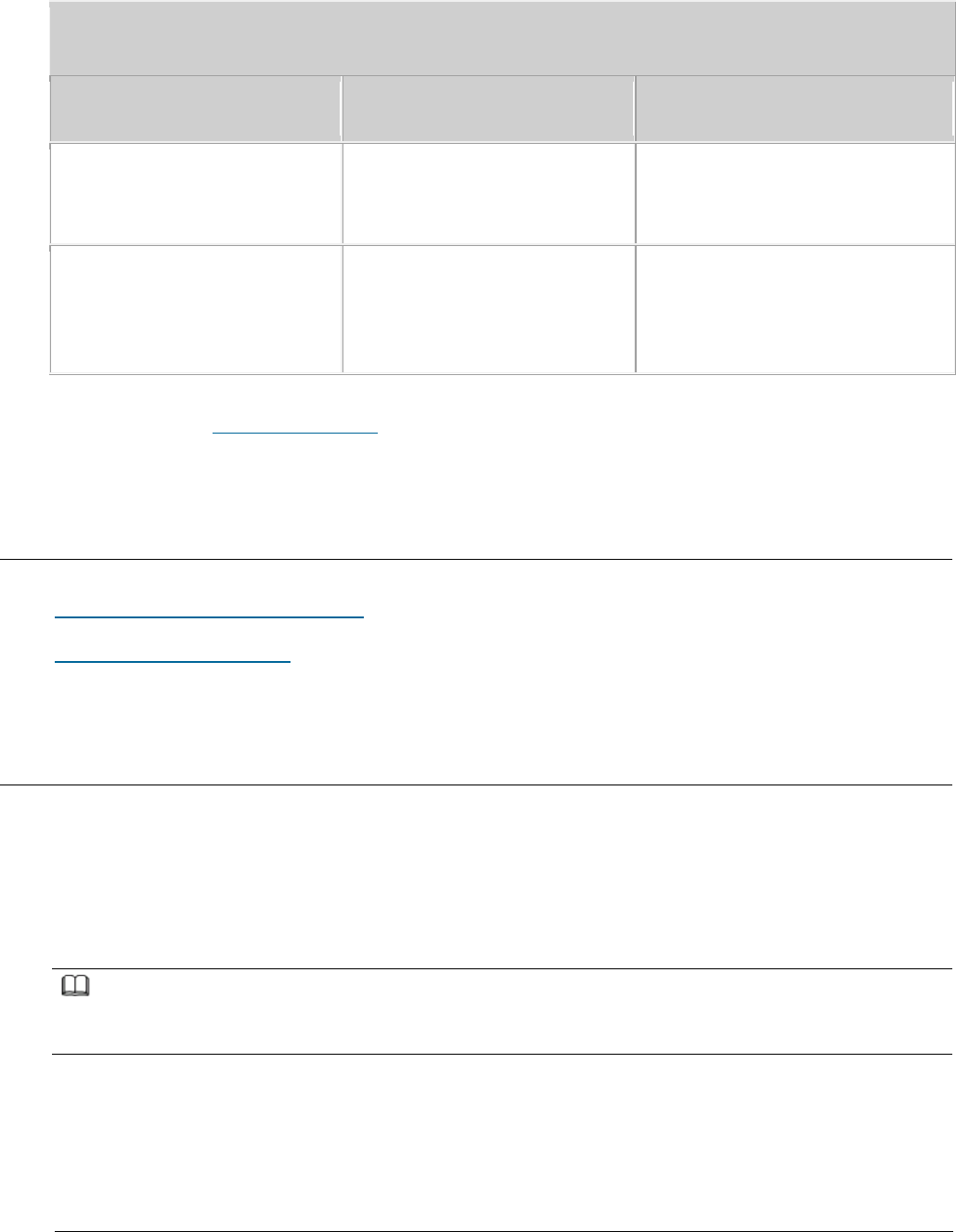
Issue 01 (2017-05-10)
Huawei Proprietary and Confidential
Copyright © Huawei Technologies Co., Ltd.
62
Table 1 User name and default password in the eAN3810A system
Category
User Name and Default
Password
Remarks
Operation and maintenance
User name: admin
Password: hwbs@com
Used for logging in to the Web
LMT. User admin can download
and upload data through FTP.
U2000 interconnection
User name: emscomm
Password: ei*b+@b#6Nh(tS1j
Used by a OSS user to log in
to the eAN3810A. User admin
can download and upload data
through FTP.
Parent topic: Reference Information
4 Installation and commissioning
eAN3810A Hardware Installation Guide
eAN3810A Deployment Guide
4.1 eAN3810A Hardware Installation Guide
Overview
This document describes the process of installing eAN3810A.
Product Version
NOTE:
Unless otherwise stated, "eNodeB", "Pico", "eAN", and "AirNode" in this document refer to the
3810 series AirNode.
The 3810 series AirNode is a base station that provides communications services
in Huawei OneAir solution. The following table lists the product name and
product version related to the 3810 series AirNode.

Issue 01 (2017-05-10)
Huawei Proprietary and Confidential
Copyright © Huawei Technologies Co., Ltd.
63
Product Name
Product Version
eAN3810A
V100R001C00
Intended Audience
This document is intended for installation engineers.
Organization
Installation Preparations
Before starting the installation, you must obtain the required reference
documents, tools, and instruments, and familiarize yourself with the skills
required.
Information About the Installation
This section describes the information that you must be familiar with before
installing a eAN3810A, including the eAN3810A hardward infomation, installation
scenarios, installation space and environment requirements.
Unpacking the Equipment
This section describes how to unpack and check the delivered equipment to ensure
that all the materials are included and intact.
Installation Process
This section describes the eAN3810A installation process.
Obtaining the ESN
Before installing the eAN3810A, record its electronic serial number (ESN) for
future use during commissioning.
(Optional) Installing a Micro SD Card
This section describes how to install a micro SD card in the eAN3810A.
Installing the eAN3810A
This section describes the eAN3810A installation process.
Installing the Auxiliary Devices
This section describes the procedure and precautions for installing the
auxiliary devices.
Installing Cables
This section describes the procedures for installing eAN3810A cables and
auxiliary devices cables.

Issue 01 (2017-05-10)
Huawei Proprietary and Confidential
Copyright © Huawei Technologies Co., Ltd.
64
Checking Hardware Installation
eAN3810A hardware installation checking includes hardware and cable installation
checking.
Power-On Check on the eAN3810A
This section describes the procedure for performing a power-on check on the
eAN3810A.
Appendix
This section describes reference information during installation.
Parent topic: Installation and commissioning
4.1.1 Installation Preparations
Before starting the installation, you must obtain the required reference
documents, tools, and instruments, and familiarize yourself with the skills
required.
Reference Documents
Before the installation, you must be familiar with reference documents.
Tools and Instruments
You must prepare the following tools and instruments before the installation.
Requirements for Installation Personnel
This section describes requirements for installation engineers. They must be
qualified and trained, and familiar with correct operation methods and safety
precautions before performing any operations.
Parent topic: eAN3810A Hardware Installation Guide
4.1.1.1 Reference Documents
Before the installation, you must be familiar with reference documents.
The following reference documents are required during eAN3810A installation:
Health and Safety
Equipment Safety
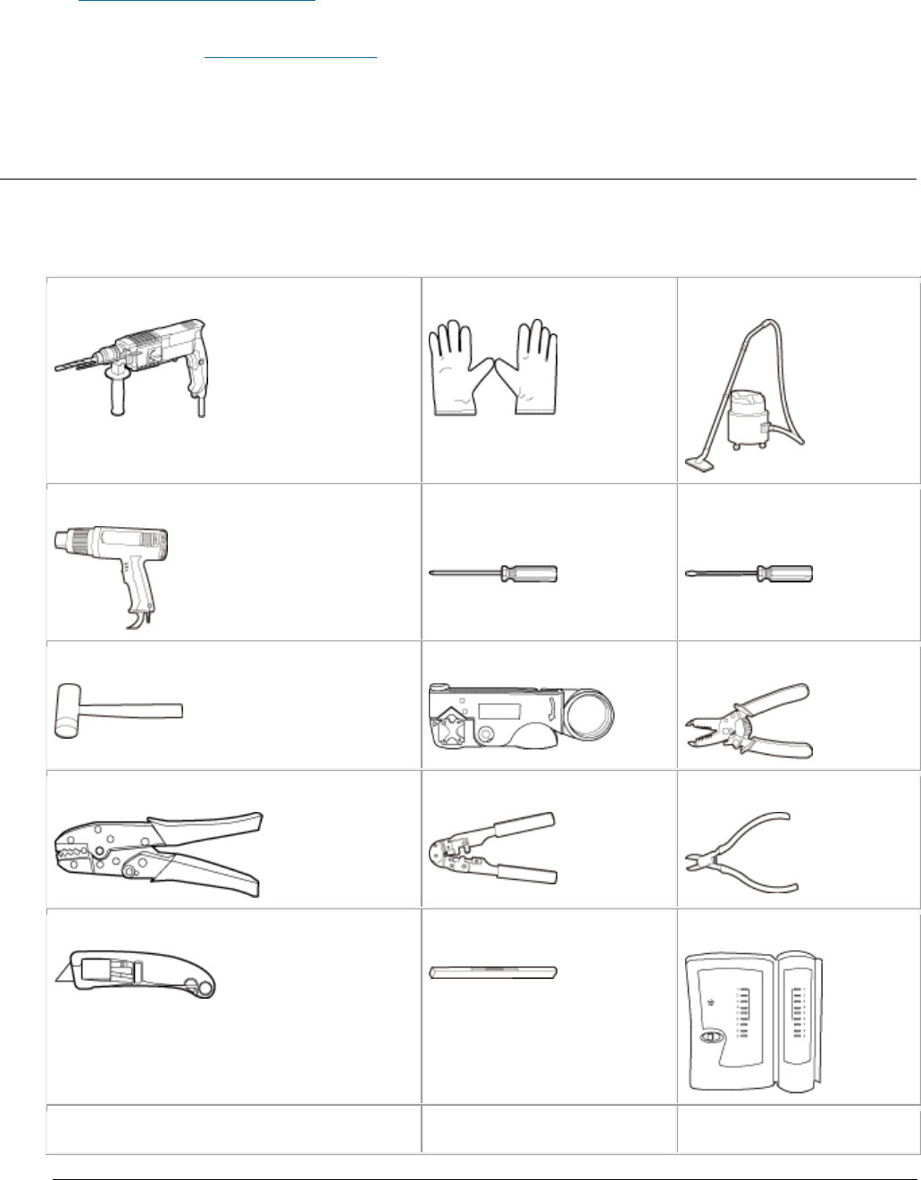
Issue 01 (2017-05-10)
Huawei Proprietary and Confidential
Copyright © Huawei Technologies Co., Ltd.
65
eAN3810A Hardware Description
Parent topic: Installation Preparations
4.1.1.2 Tools and Instruments
You must prepare the following tools and instruments before the installation.
Hammer drill (a φ12 bit)
ESD gloves
Vacuum cleaner
Heat gun
Phillips screwdriver
(M3 to M6)
Flat-head screwdriver
(M3 to M6)
Rubber mallet
COAX crimping tool
Wire stripper
Power cable crimping tool
RJ45 crimping tool
Diagonal plier
Utility knife
Level
Network cable tester
Adjustable wrench (size ≥ 32 mm
Torque screwdriver
Marker (diameter ≤
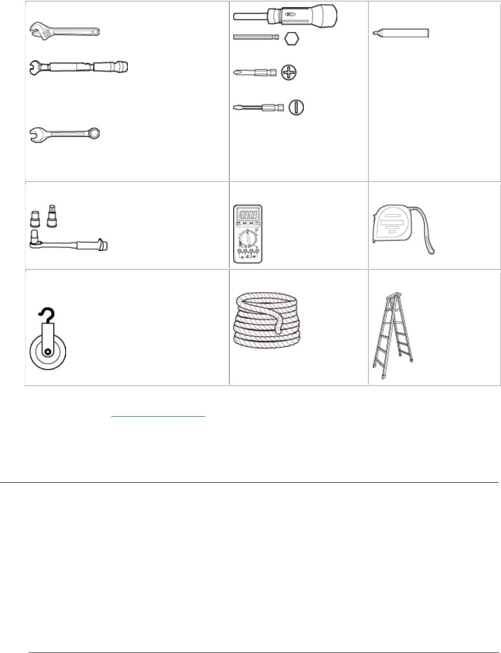
Issue 01 (2017-05-10)
Huawei Proprietary and Confidential
Copyright © Huawei Technologies Co., Ltd.
66
[1.26 in.])
Torque wrench
Size: 16 mm (0.63 in.) and 22 mm
(0.87 in.)
Combination wrench
Size: 16 mm (0.63 in.) and 22 mm
(0.87 in.)
3mm or 5mm
(M3 to M6)
(M3 to M6)
10 mm [0.39 in.])
Torque socket (M6 or M10)
Multimeter
Measuring tape
Fixed pulley(weight-bearing
capacity > 500 kg or 1102.5 lb)
Lifting sling
Ladder
Parent topic: Installation Preparations
4.1.1.3 Requirements for Installation Personnel
This section describes requirements for installation engineers. They must be
qualified and trained, and familiar with correct operation methods and safety
precautions before performing any operations.
Before the installation, pay attention to the following items:
Technical engineers must take Huawei training and be familiar with proper
installation and operation methods.

Issue 01 (2017-05-10)
Huawei Proprietary and Confidential
Copyright © Huawei Technologies Co., Ltd.
67
The number of installation personnel depends on the engineering schedule and
installation environment. Generally, two to three persons are required.
Generally, only three to five onsite personnel are necessary.
Parent topic: Installation Preparations
4.1.2 Information About the Installation
This section describes the information that you must be familiar with before
installing a eAN3810A, including the eAN3810A hardward infomation, installation
scenarios, installation space and environment requirements.
Hardware Device Information
This section describes the hardware information you should know before
installing the eAN3810A.
Installation Options and Restrictions
The eAN3810A can be installed on a wall or pole. Installation scenarios must
meet heat-dissipation and waterproofing requirements of the eAN3810A.
Installation Clearance and Space Requirements
This section describes the recommended and minimum clearances for a eAN3810A.
Installation Environment Requirements
The installation environment of a eAN3810A involves the running environment
specifications for the eAN3810A.
Parent topic: eAN3810A Hardware Installation Guide
4.1.2.1 Hardware Device Information
This section describes the hardware information you should know before
installing the eAN3810A.
eAN3810A hardware includes eAN3810A main equipment, auxiliary devices, mounting
kits, and cables. For details, see sections in
eAN3810A Hardware Description
,
which are listed in Table 1.
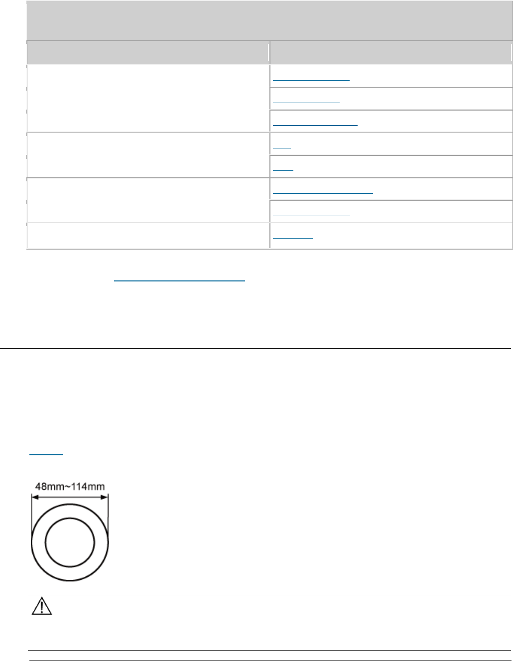
Issue 01 (2017-05-10)
Huawei Proprietary and Confidential
Copyright © Huawei Technologies Co., Ltd.
68
Table 1 Hardware information
Category
Sections in eAN3810A Hardware Description
eAN3810A main equipment
eAN3810A Exterior
eAN3810A Ports
eAN3810A Indicators
Auxiliary device
PSE
Dock
Mounting kits
eAN3810A Mounting Kits
Dock Mounting Kits
Cables
Cable List
Parent topic: Information About the Installation
4.1.2.2 Installation Options and Restrictions
The eAN3810A can be installed on a wall or pole. Installation scenarios must
meet heat-dissipation and waterproofing requirements of the eAN3810A.
Installation on a Pole
Figure 1 shows the diameter of a pole for installing an eAN3810A.
Figure 1 Diameter of a pole for installing a eAN3810A
NOTICE:
The diameter of a pole for installing a eAN3810A ranges from 48 mm (1.89 in.)
to 114 mm (4.49 in.). The recommended diameter is 60 mm (2.36 in.).
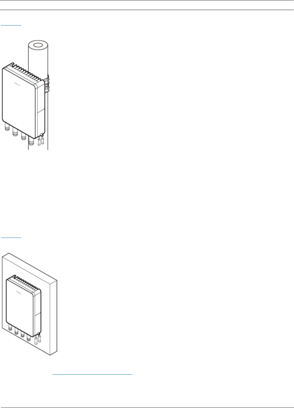
Issue 01 (2017-05-10)
Huawei Proprietary and Confidential
Copyright © Huawei Technologies Co., Ltd.
69
The recommended thickness of the pole wall is 3.5 mm (0.14 in.) or above.
Figure 2 shows the eAN3810A installed on a pole.
Figure 2 A eAN3810A installed on a pole
Installation on a Wall
The wall for installing eAN3810A must meet the following requirements:
The wall can bear a load at least four times the weight of a eAN3810A.
The screws must be tightened with a torque of 30 N·m. This ensures the
screws work properly and the wall remains intact without cracks in it.
Figure 3 shows the eAN3810A installed on a pole.
Figure 3 A eAN3810A installed on a wall
Parent topic: Information About the Installation

Issue 01 (2017-05-10)
Huawei Proprietary and Confidential
Copyright © Huawei Technologies Co., Ltd.
70
4.1.2.3 Installation Clearance and Space
Requirements
This section describes the recommended and minimum clearances for a eAN3810A.
Clearance for a eAN3810A
When the eAN3810A is installed on a wall or pole, the minimum clearance is
required for easy cabling and operation and maintenance (O&M). Based on the
engineering practice, the recommendation for the installation clearance is
provided.
The recommended clearances are for customers, ensuring normal running and
providing appropriate space for O&M. If installation space is sufficient,
leave the recommended clearances after installing equipment.
The minimum clearance ensures normal operation and heat dissipation, but O&M
activities such as checking indicator status and opening the cover plate of a
cabling cavity cannot be properly conducted. If installation space is
restricted, leave the minimum clearance after installing equipment.
Figure 1 show the clearances for installing a eAN3810A.
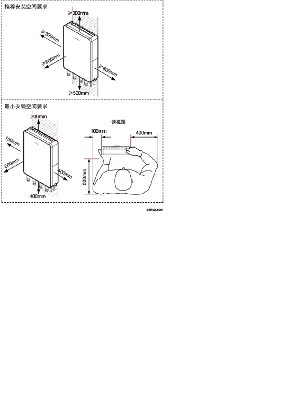
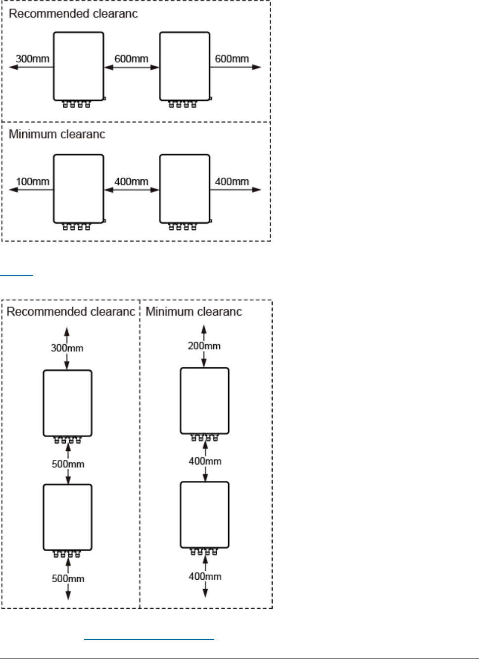

Issue 01 (2017-05-10)
Huawei Proprietary and Confidential
Copyright © Huawei Technologies Co., Ltd.
73
4.1.2.4 Installation Environment Requirements
The installation environment of a eAN3810A involves the running environment
specifications for the eAN3810A.
Running Environment Specifications
Table 1 shows the environment specifications for the eAN3810A.
Table 1 Environment specifications of eAN3810A
Item
Specifications
Operating temperature
-40ºC to +45ºC (with solar radiation)
-40ºC to +50ºC (without solar radiation)
NOTE:
At -40ºC to -20ºC, the AirNode can start up, but its
performance cannot meet requirements. At -20ºC to
+50ºC, the performance of the AirNode meets
requirements.
Storage temperature
-40ºC to +70ºC
Relative humidity
5% RH to 95% RH
Absolute humidity
1 g/m3 to 30 g/m3
Atmospheric pressure
70 kPa to 106 kPa
Protection class
IP65
Requirements for the Installation Scenarios
To ensure proper heat dissipation of the eAN3810A, the following requirements
must be met:
The eAN3810A cannot be installed in an enclosed cabinet without a cooling
system.
The eAN3810A cannot be installed in an enclosed camouflage box.
The eAN3810A cannot be installed in an enclosed equipment room without a
cooling system.
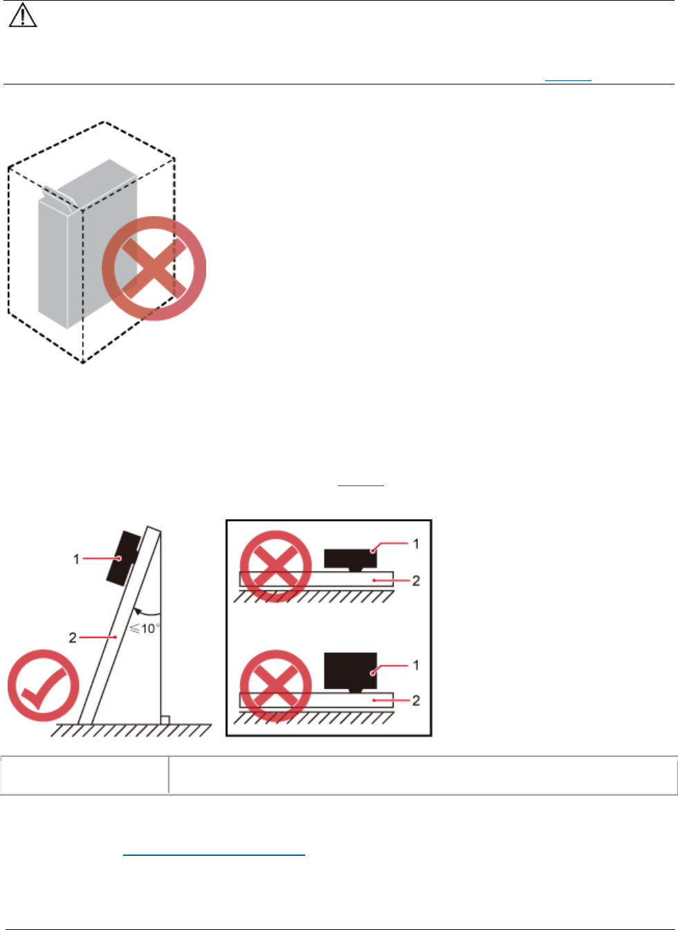
Issue 01 (2017-05-10)
Huawei Proprietary and Confidential
Copyright © Huawei Technologies Co., Ltd.
74
NOTICE:
If the eAN3810A is inappropriately installed, heat dissipation of the eAN3810A
deteriorates and the eAN3810A may not work properly, as shown in Figure 1.
Figure 1 Inappropriately installed eAN3810A
Requirements for the Installation methods
To ensure the heat dissipation of the eAN3810A and waterproofing of the ports at
the bottom of the eAN3810A, the vertical deviation angle of a eAN3810A must be
less than or equal to 10°, as shown in Figure 2.
Figure 2 Requirements for the vertical deviation angle of a eAN3810A
(1) eAN3810A
(2) Installation support (pole or wall)
Parent topic: Information About the Installation
Issue 01 (2017-05-10)
Huawei Proprietary and Confidential
Copyright © Huawei Technologies Co., Ltd.
75
4.1.3 Unpacking the Equipment
This section describes how to unpack and check the delivered equipment to ensure
that all the materials are included and intact.
Context
NOTE:
When transporting, moving, or installing the equipment, components, or parts, you must:
Prevent them from colliding with doors, walls, shelves, or other objects.
Wear clean gloves, and avoid touching the equipment, components, or parts with bare hands,
sweat-soaked gloves, or dirty gloves.
NOTICE:
Power on an eAN3810A within 24 hours after unpacking it. If you power off an
eAN3810A for maintenance, restore power to the eAN3810A within 24 hours.
Procedure
1. Count the total number of the shipments.
If...
Then...
The total number of the components is consistent with
that recorded in the packing lists on all packing boxes
Go to 2.
The total number of the components is inconsistent with
that recorded in the packing lists on all packing boxes
Report the problems and causes
to the local Huawei office.
2. Check the exterior of each packing box.
If...
Then...
The exterior of each packing box is
intact
Go to 3.
It is damaged or soaked
Report the problems and causes to the local
Huawei office.
3. Check the type and quantity of the equipment in the boxes according to the
packing list.
If...
Then...
Issue 01 (2017-05-10)
Huawei Proprietary and Confidential
Copyright © Huawei Technologies Co., Ltd.
76
If...
Then...
The type and number are consistent with the
packing list on each packing list
Sign the
Packing List
with the
operator.
There is any shortage, wrong delivery, or
damaged equipment
Report the problems and causes to the
local Huawei office.
4. CAUTION:
5. To protect the equipment from damage, keep the unpacked equipment and
packing materials indoors. To help find out the cause of any damage in the
future, take photos of the storeroom, rusted or eroded equipment, packing
cases, and packing materials, and then file the photos.
Parent topic: eAN3810A Hardware Installation Guide
4.1.4 Installation Process
This section describes the eAN3810A installation process.
Figure 1 shows the eAN3810A installation process.
Figure 1 eAN3810A installation process
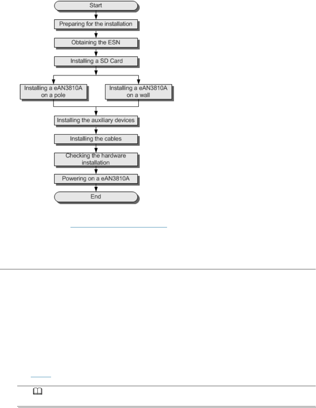
Issue 01 (2017-05-10)
Huawei Proprietary and Confidential
Copyright © Huawei Technologies Co., Ltd.
77
Parent topic: eAN3810A Hardware Installation Guide
4.1.5 Obtaining the ESN
Before installing the eAN3810A, record its electronic serial number (ESN) for
future use during commissioning.
Context
The ESN uniquely identifies a device and is required during commissioning.
Procedure
1. Remove the backup ESN label from the surface of the eAN3810A. as shown in
Figure 1.
NOTE:
Before removing the backup SN label, photograph it.
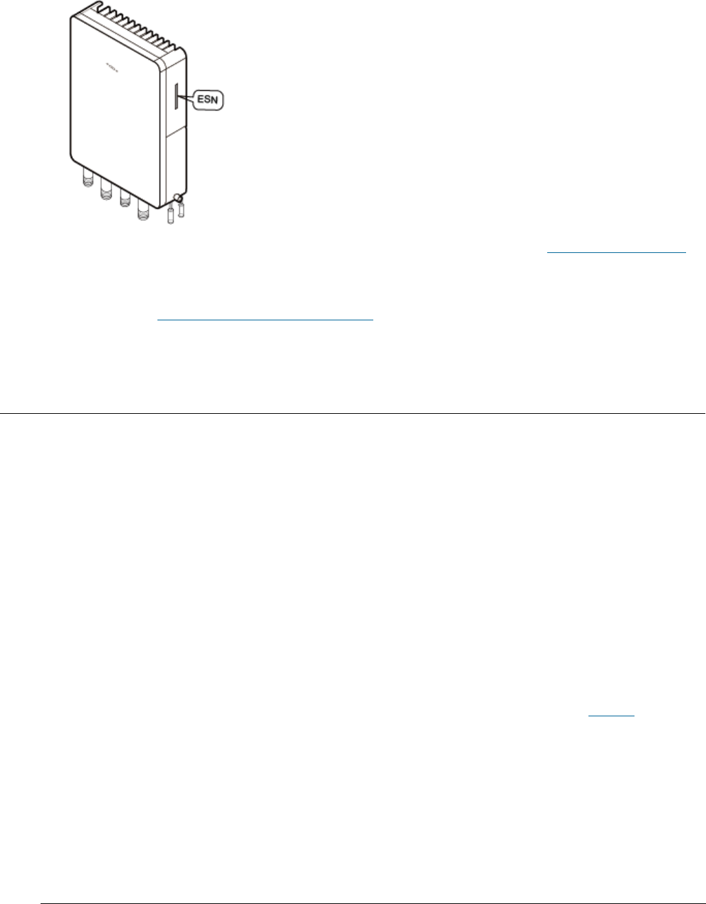
Issue 01 (2017-05-10)
Huawei Proprietary and Confidential
Copyright © Huawei Technologies Co., Ltd.
78
Figure 1 Removing the ESN label
2. Record the ESN by using the template described in section ESN Collection Template,
and report it to the eAN3810A commissioning personnel.
Parent topic: eAN3810A Hardware Installation Guide
4.1.6 (Optional) Installing a Micro SD Card
This section describes how to install a micro SD card in the eAN3810A.
Prerequisites
Software and configuration data files need to be prepared for the micro SD card
to be installed. For detailed operations, see
eAN3810A Deployment Guide
.
Procedure
1. Wear ESD gloves.
2. Use an M5 inner hexagon screwdriver to loosen a screw on the cabling cavity
panel and open the cabling cavity on the side.
3. Install a micro SD card in the micro SD card slot, as shown in Figure 1.
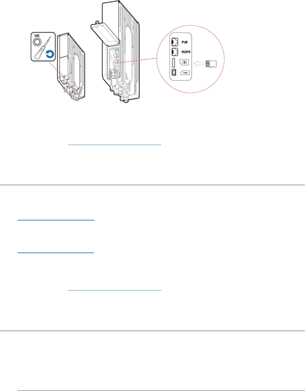
Issue 01 (2017-05-10)
Huawei Proprietary and Confidential
Copyright © Huawei Technologies Co., Ltd.
79
Figure 1 Installing a micro SD card
4. Cover the plate for the cabling cavity and use the screwdriver to tighten
the screw.
Parent topic: eAN3810A Hardware Installation Guide
4.1.7 Installing the eAN3810A
This section describes the eAN3810A installation process.
Installing eAN3810A on a Pole
This section describes the procedure and precautions for installing an eAN3810A
on a pole.
Installing eAN3810A on a Wall
This section describes the procedure and precautions for installing an eAN3810A
on a wall.
Parent topic: eAN3810A Hardware Installation Guide
4.1.7.1 Installing eAN3810A on a Pole
This section describes the procedure and precautions for installing an eAN3810A
on a pole.
Context
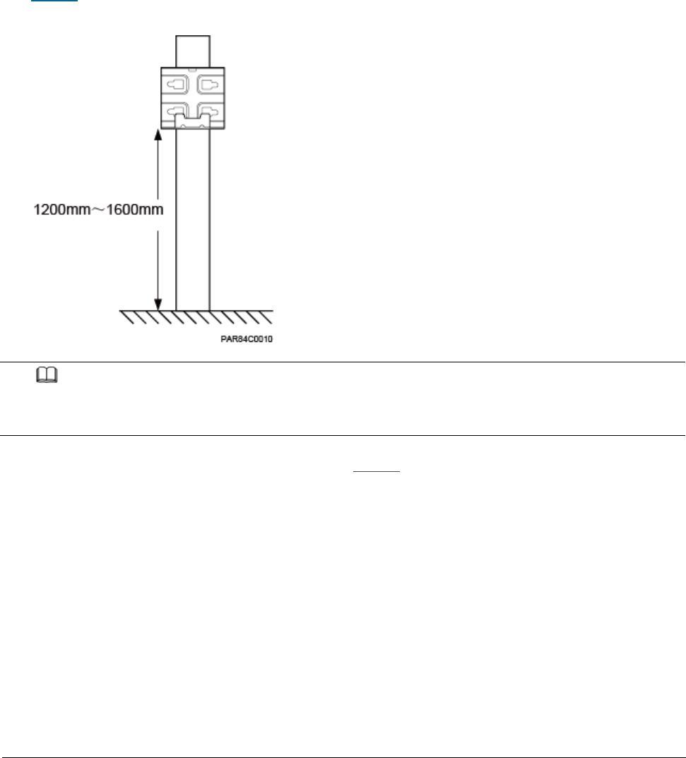
Issue 01 (2017-05-10)
Huawei Proprietary and Confidential
Copyright © Huawei Technologies Co., Ltd.
80
Do not stand an eAN3810A upright because the RF ports cannot support the
weight of the eAN3810A.
Place a foam pad or cardboard under an eAN3810A to protect the eAN3810A
housing from damage during the installation.
Procedure
1. Determine a position for installing the separate mounting kit, as shown in
Figure 1.
Figure 1 Distance between the separate mounting kit and the ground
NOTE:
It is recommended that the mounting kits be installed at a position 1200 mm (47.24 in.) to
1600 mm (59.06 in.) high above the ground.
2. Install the mounting kit, as shown in Figure 2.
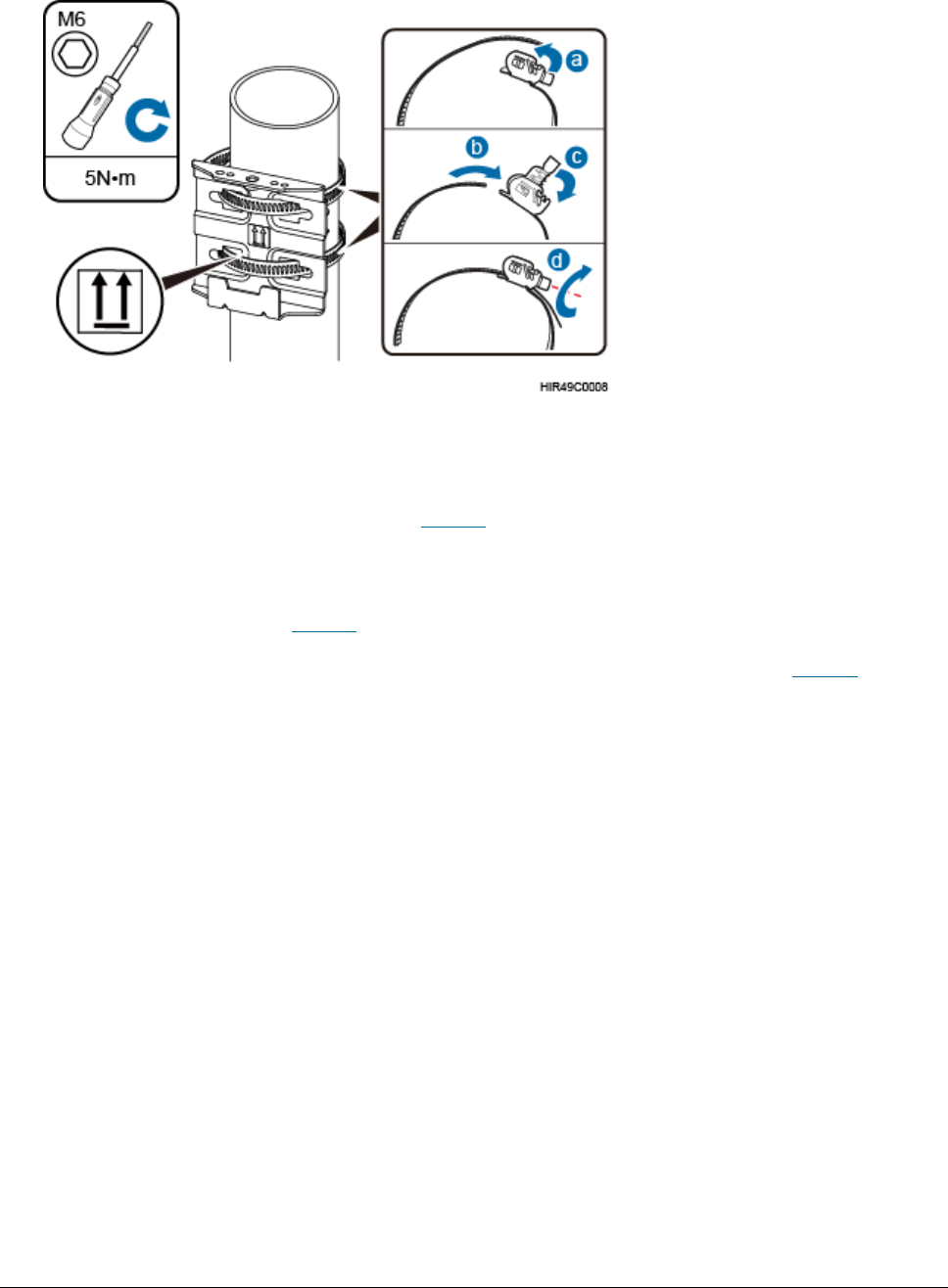
Issue 01 (2017-05-10)
Huawei Proprietary and Confidential
Copyright © Huawei Technologies Co., Ltd.
81
Figure 2 Installing the eAN3810A mounting kit
a. Determine a position for installing the eAN3810A. Then, place the
separate mounting kit onto the pole, thread the hose clamp through the
mounting kit, and encircle the pole with the hose clamp, as shown by
illustrations a, b, and c in Figure 2.
b. Use an M6 inner hexagon screwdriver to tighten the bolt on each hose
clamp to 7 N·m (61.96 lbf·in.) to secure the mounting kit, as shown by
illustration d in Figure 2.
3. Secure the eAN3810A onto the separate mounting kit, as shown in Figure 3.
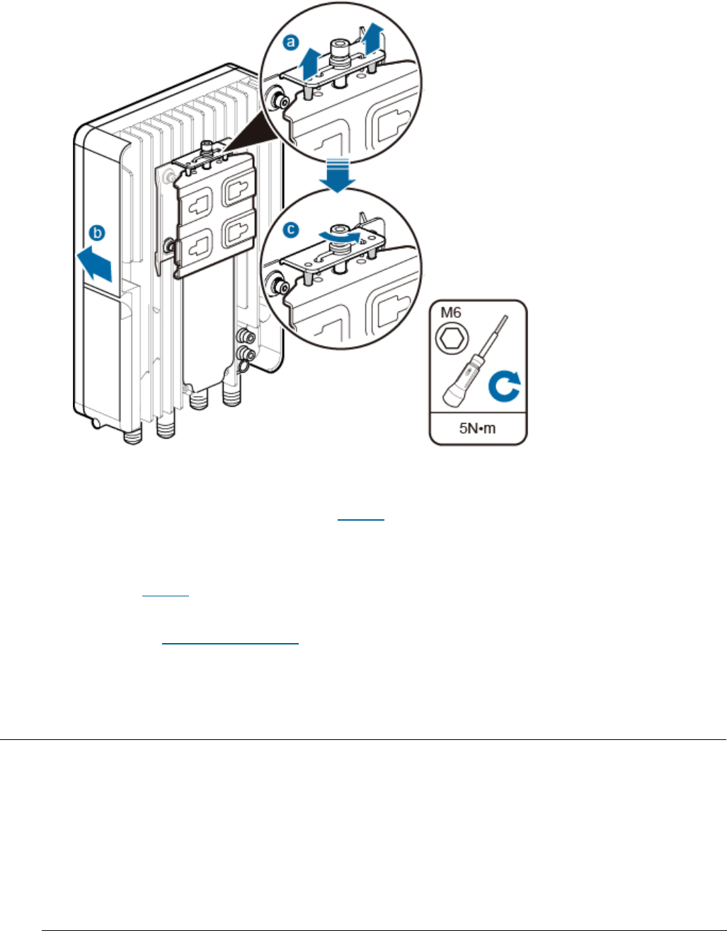
Issue 01 (2017-05-10)
Huawei Proprietary and Confidential
Copyright © Huawei Technologies Co., Ltd.
82
Figure 3 Securing the eAN3810A onto the mounting kit
a. Hang the two dowels on the top of the eAN3810A attachment plate onto the
mounting kit, and push the eAN3810A until it snaps into place, as shown
by illustrations a and b in Figure 3.
b. Use the M6 inner hexagon screwdriver to tighten the screw on the top of
the attachment plate to 5 N·m (44.25 lbf·in.), as shown by illustration
c in Figure 3.
Parent topic: Installing the eAN3810A
4.1.7.2 Installing eAN3810A on a Wall
This section describes the procedure and precautions for installing an eAN3810A
on a wall.
Context
The wall for installing eAN3810As must meet the following requirements:
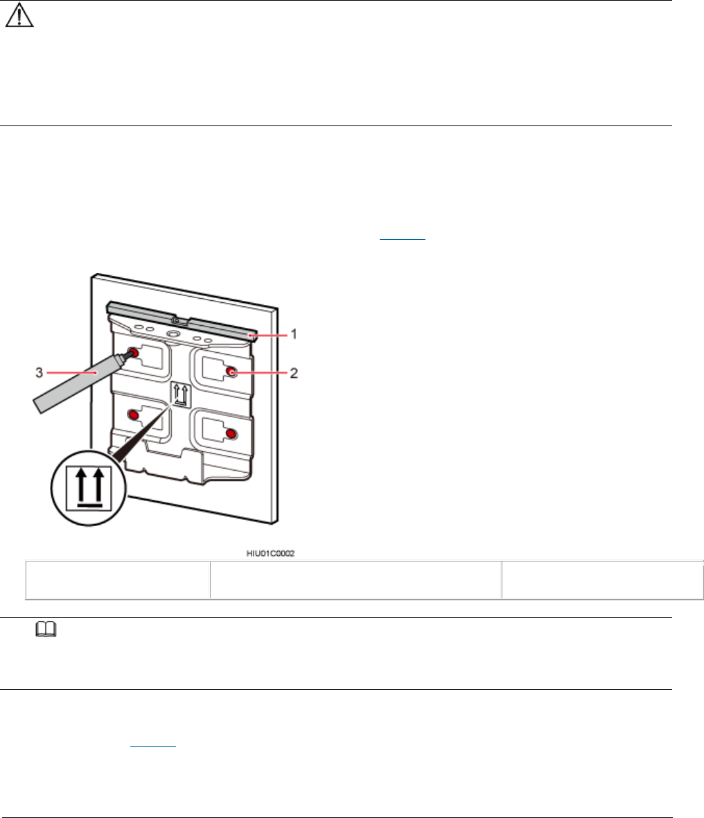
Issue 01 (2017-05-10)
Huawei Proprietary and Confidential
Copyright © Huawei Technologies Co., Ltd.
83
The wall must be able to bear a weight four times heavier than the eAN3810A's
weight.
Expansion bolts must be tightened to 30 N·m (265.52 lbf·in.) to ensure that
the bolt assemblies work properly and the wall remains intact.
NOTICE:
Do not stand an eAN3810A upright because the RF ports cannot support the
weight of the eAN3810A.
Place a foam pad or cardboard under an eAN3810A to protect the eAN3810A
housing from damage during the installation.
Procedure
1. Determine a position for installing the eAN3810A on a wall, use a level to
verify that the marking-off template is placed horizontally, and then use a
marker to mark anchor points, as shown in Figure 1.
Figure 1 Marking anchor points
(1) Level
(2) Tapped hole
(3) Marker
NOTE:
It is recommended that the separate mounting kit be 1200 mm (47.24 in.) to 1600 mm (62.99
in.) above the ground.
2. Drill holes at the anchor points and install expansion bolts in the holes,
as shown in Figure 2.
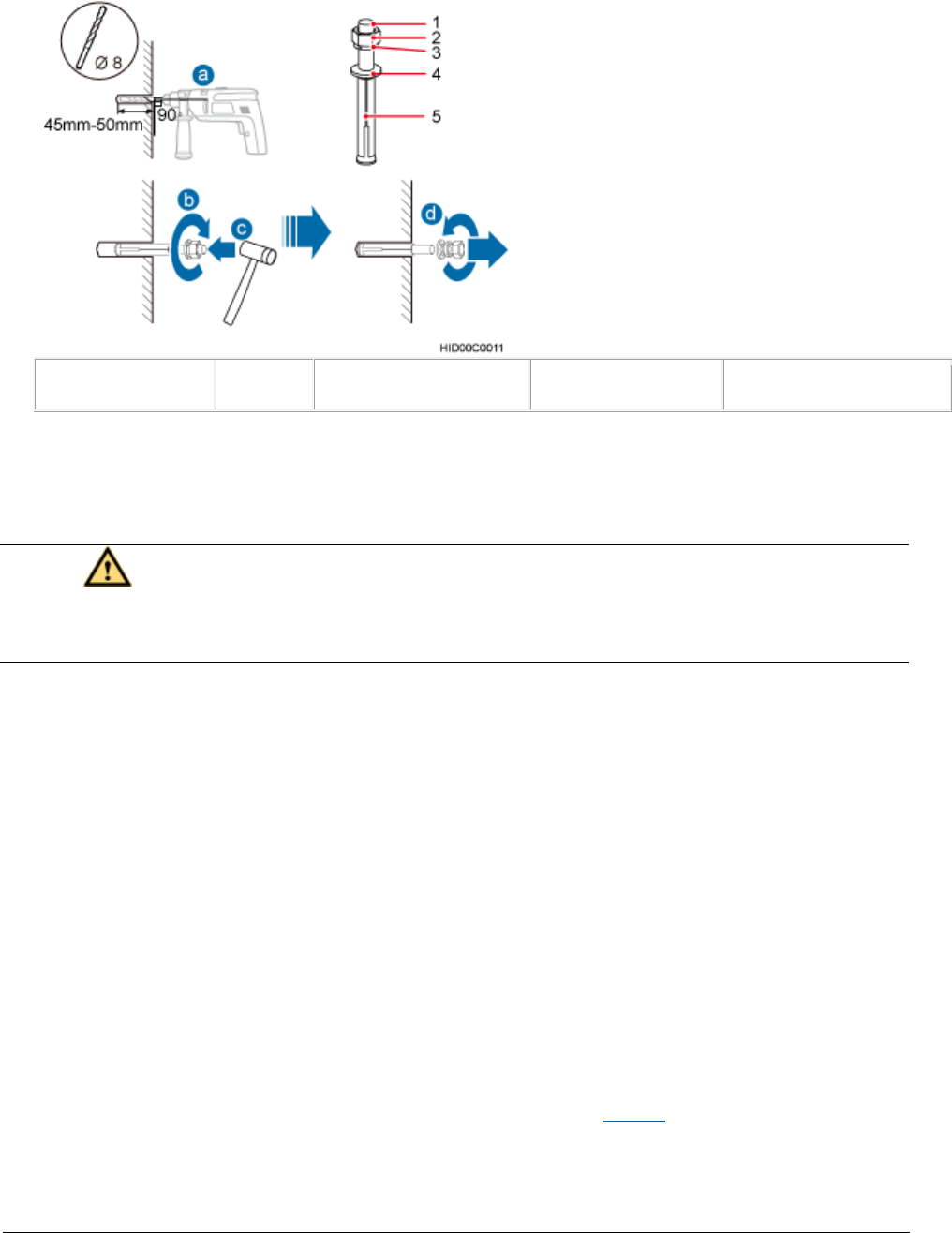
Issue 01 (2017-05-10)
Huawei Proprietary and Confidential
Copyright © Huawei Technologies Co., Ltd.
84
Figure 2 Drilling a hole and inserting an expansion bolt assembly
(1) M6x60 bolt
(2) Nut
(3) Spring washer
(4) Flat washer
(5) Expansion tube
a. Use a hammer drill with a φ8 bit to drill holes vertically at the marked
anchor points. Ensure that the depth of each hole ranges from 45 mm (1.77
in.) to 50 mm (1.97 in.).
CAUTION:
Take proper safety measures to protect your eyes and respiratory tract
against the dust before drilling holes.
b. Use a vacuum cleaner to clear the dust out from inside and around the
holes, and measure the distances between holes. If any of the holes is
beyond the acceptable range, mark a new anchor point and drill a new hole.
c. Tighten the expansion bolts slightly, and place each expansion bolt
vertically into each hole.
d. Use a rubber mallet to pound each expansion bolt until the corresponding
expansion tube completely enters the hole. Leave 20 mm (0.79 in.) of the
expansion bolt outside the wall.
e. Remove the M6x60 bolt, nut, spring washer, and flat washer in sequence.
3. Place the mounting kit onto the wall, insert four M6x60 bolts into the
tapped holes on the mounting kit, and tighten each bolt to 5 N·m (44.25
lbf·in.) to secure the mounting kit, as shown in Figure 3.
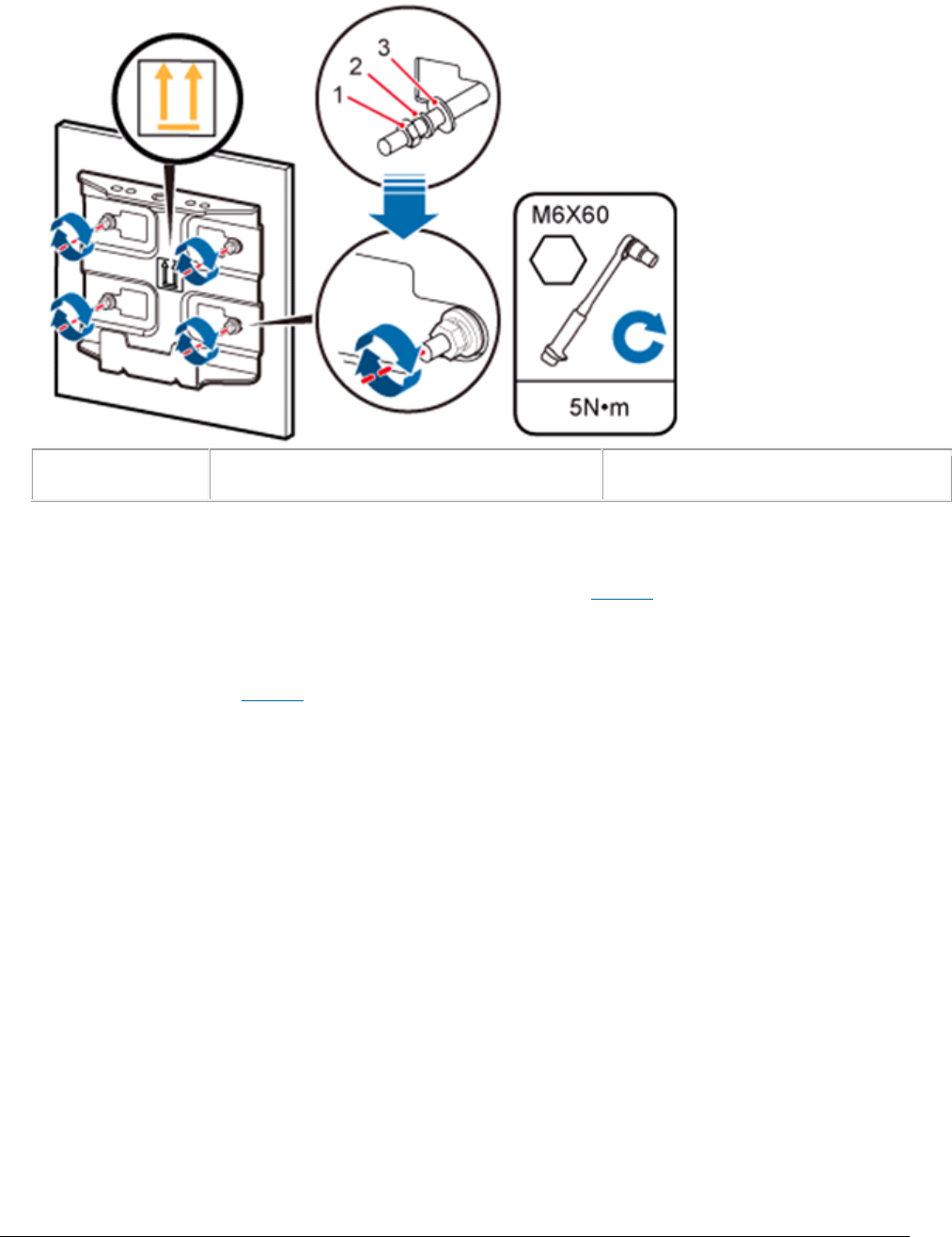
Issue 01 (2017-05-10)
Huawei Proprietary and Confidential
Copyright © Huawei Technologies Co., Ltd.
85
Figure 3 Securing the separate mounting kit
(1) Nut
(2) Spring washer
(3) Flat washer
4. Hold the eAN3810A, hang the two dowels on the top of the eAN3810A attachment
plate onto the separate mounting kit, and push the eAN3810A until it snaps
into place, as shown by illustrations a and b in Figure 4.
5. Use the M6 inner hexagon screwdriver to tighten the screw on the top of the
separate attachment plate to 5 N·m (61.96 lbf·in.), as shown by
illustration c in Figure 4.
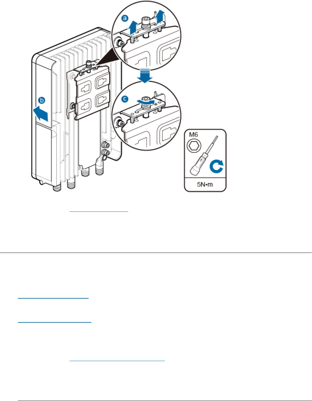
Issue 01 (2017-05-10)
Huawei Proprietary and Confidential
Copyright © Huawei Technologies Co., Ltd.
86
Figure 4 Securing the eAN3810A onto the mounting kit
Parent topic: Installing the eAN3810A
4.1.8 Installing the Auxiliary Devices
This section describes the procedure and precautions for installing the
auxiliary devices.
(Optional) Installing a Dock
This section describes the procedure and precautions for installing a dock.
(Optional) Installing the PSE
This section describes the procedure and precautions for installing the PSE on a
wall.
Parent topic: eAN3810A Hardware Installation Guide

Issue 01 (2017-05-10)
Huawei Proprietary and Confidential
Copyright © Huawei Technologies Co., Ltd.
87
4.1.8.1 (Optional) Installing a Dock
This section describes the procedure and precautions for installing a dock.
Installing a Dock on a Pole
This section describes the procedure and precautions for installing the Dock on
a pole.
Installing a Dock on a Wall
This section describes the procedure and precautions for installing the Dock on
a wall.
Parent topic: Installing the Auxiliary Devices
4.1.8.1.1 Installing a Dock on a Pole
This section describes the procedure and precautions for installing the Dock on
a pole.
Procedure
1. Use an M4 inner hexagon screwdriver to remove the Dock integrated mounting
bracket, install the Dock separated mounting bracket instead, and tighten
the four screws to 2 N·m (17.70 lbf·in.), as shown in Figure 1.
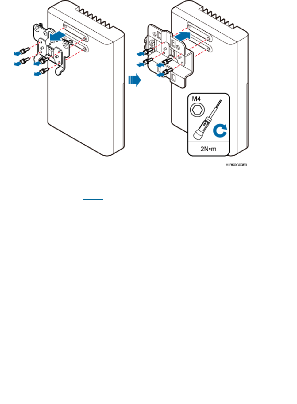
Issue 01 (2017-05-10)
Huawei Proprietary and Confidential
Copyright © Huawei Technologies Co., Ltd.
88
Figure 1 Replacing the Dock mounting bracket
2. Route two hose clamps through the up and down mounting holes on the Dock
separate mounting bracket, but do not route the steel belts through the
locks, as shown in Figure 2.
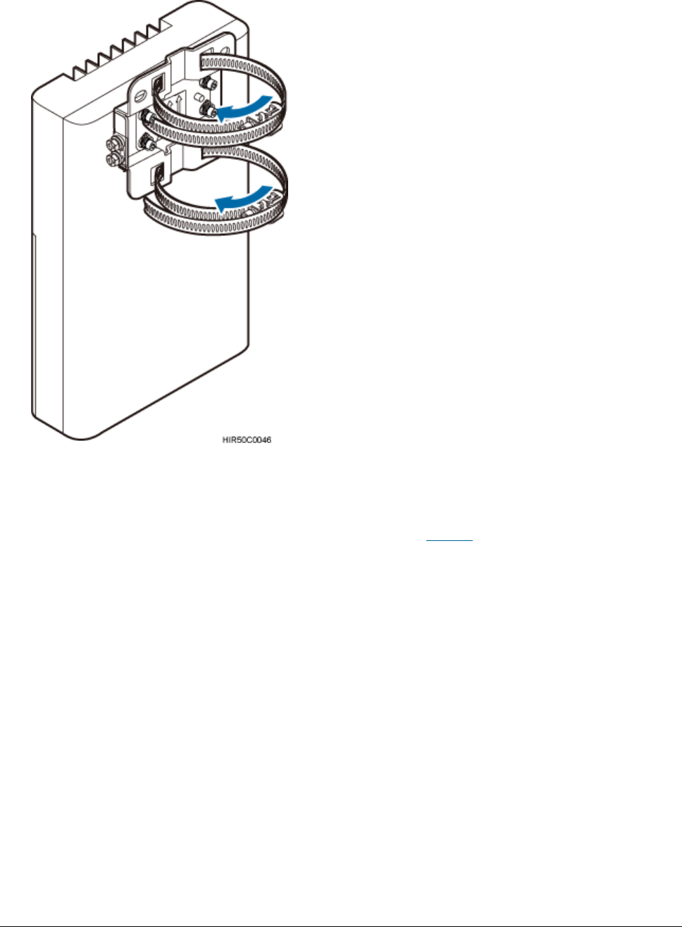
Issue 01 (2017-05-10)
Huawei Proprietary and Confidential
Copyright © Huawei Technologies Co., Ltd.
89
Figure 2 Routing hose clamps through the Dock separate mounting bracket
3. Put the Dock in the installation position, route two hose clamps through the
pole and the steel belts through the locking connectors, partially tighten
the screws, and use an M6 inner hexagon torque screwdriver to tighten the
screws to 5 N·m (44.25 lbf·in.), as shown in Figure 3.
Ensure that your body is close to the module when tightening hose clamps.
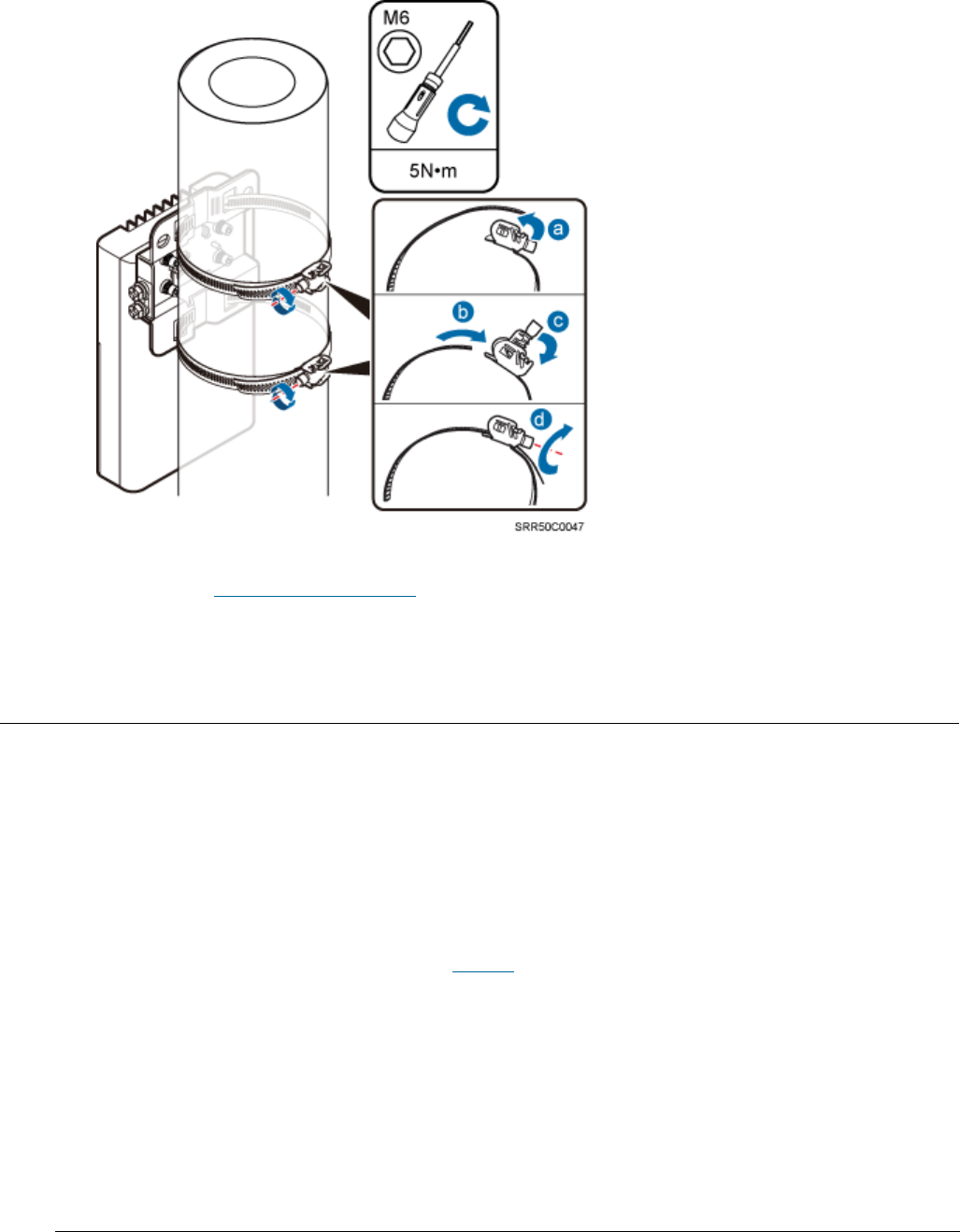
Issue 01 (2017-05-10)
Huawei Proprietary and Confidential
Copyright © Huawei Technologies Co., Ltd.
90
Figure 3 Tightening hose clamps
Parent topic: (Optional) Installing a Dock
4.1.8.1.2 Installing a Dock on a Wall
This section describes the procedure and precautions for installing the Dock on
a wall.
Procedure
1. Place the Dock separate mounting bracket against the wall, use a level to
verify that the mounting bracket is horizontally placed, and use a marker to
mark anchor points, as shown in Figure 1.
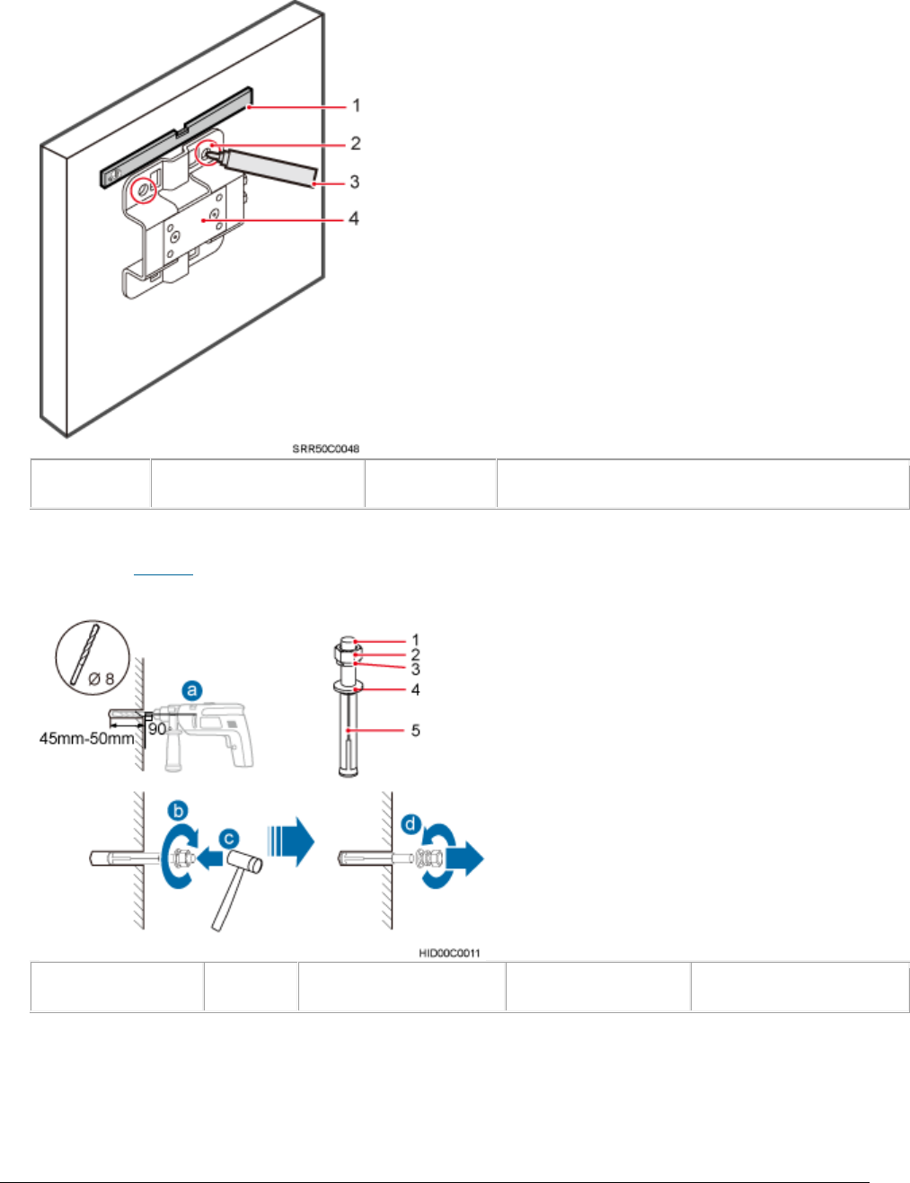
Issue 01 (2017-05-10)
Huawei Proprietary and Confidential
Copyright © Huawei Technologies Co., Ltd.
91
Figure 1 Marking anchor points
(1) Level
(2) Mounting hole
(3) Marker
(4) Dock separate mounting bracket
2. Drill holes at the anchor points, and install expansion bolt assemblies, as
shown in Figure 2.
Figure 2 Drilling holes and installing expansion bolt assemblies
(1) M6x60 bolt
(2) Nut
(3) Spring washer
(4) Flat washer
(5) Expansion tube
a. Use a hammer drill with a Ф8 drill bit to drill holes perpendicularly
with the wall at the marked anchor points. Ensure that the depth of each
hole ranges from 45 mm to 50 mm (1.77 in. to 1.97 in.) and each hole is
of the same depth.
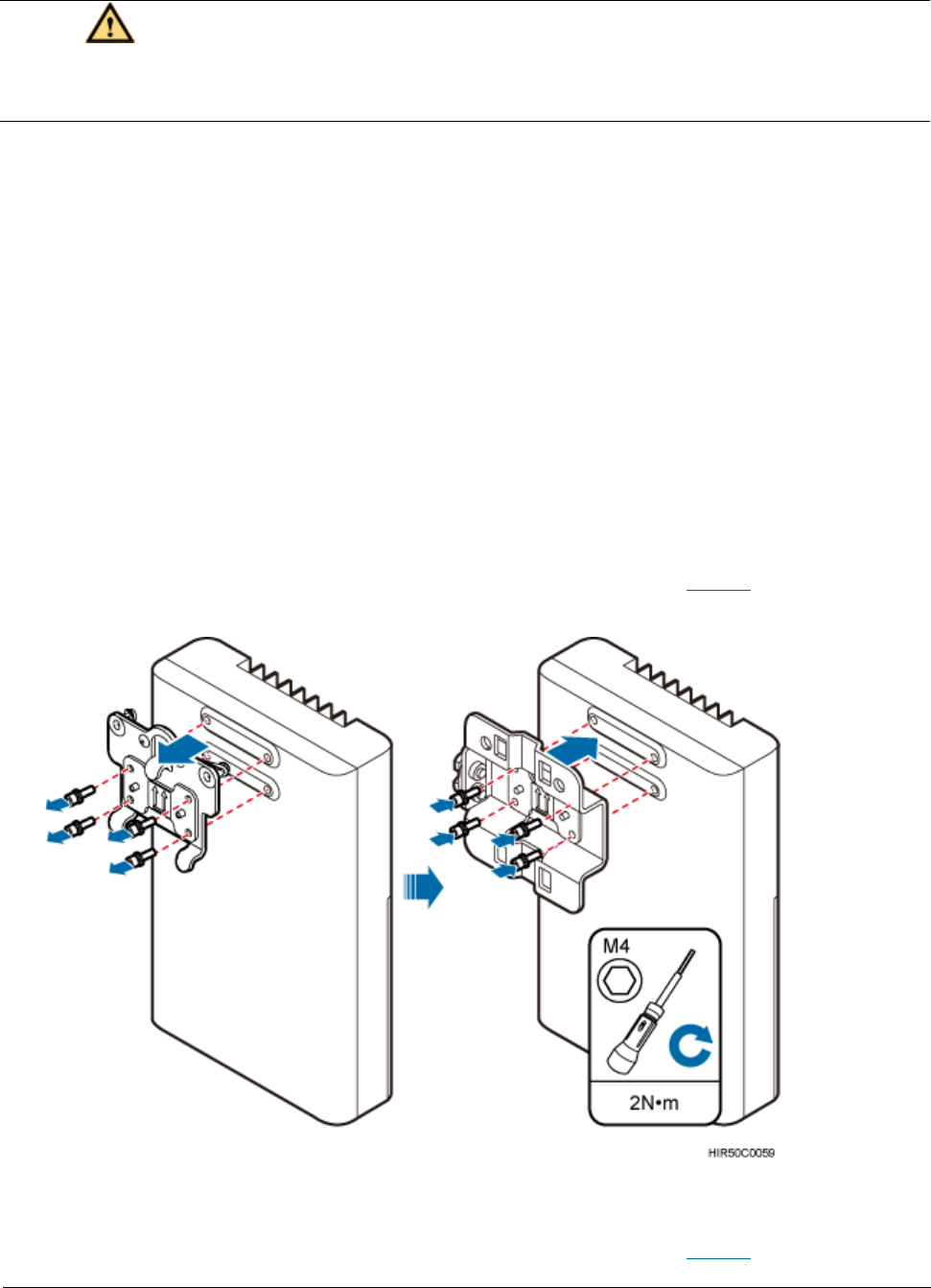
Issue 01 (2017-05-10)
Huawei Proprietary and Confidential
Copyright © Huawei Technologies Co., Ltd.
92
CAUTION:
To prevent inhalation or eye contact with dust, take adequate preventive
measures when drilling holes.
b. Use a vacuum cleaner to clear dust inside and around the holes, and then
measure the inter-hole spacing. If the spacing is too wide or too narrow,
drill holes again.
c. Tighten each expansion bolt slightly and place them perpendicularly into
each hole.
d. Hit each expansion bolt using a rubber mallet to enable the expansion
tube to enter the hole completely.
e. Remove the M6x60 bolt, nut, spring washer, and flat washer from each
expansion bolt assembly in sequence.
3. Use an M4 inner hexagon screwdriver to remove the Dock integrated mounting
bracket, install the Dock separated mounting bracket instead, and tighten
the four screws to 2 N·m (17.70 lbf·in.), as shown in Figure 3.
Figure 3 Replacing the Dock mounting bracket
4. Put the Dock to the installation position, install the separate mounting
bracket on the expansion bolts, and use an M6 socket wrench to tighten the
expansion bolts to 5 N·m (44.25 lbf·in.), as shown in Figure 4.
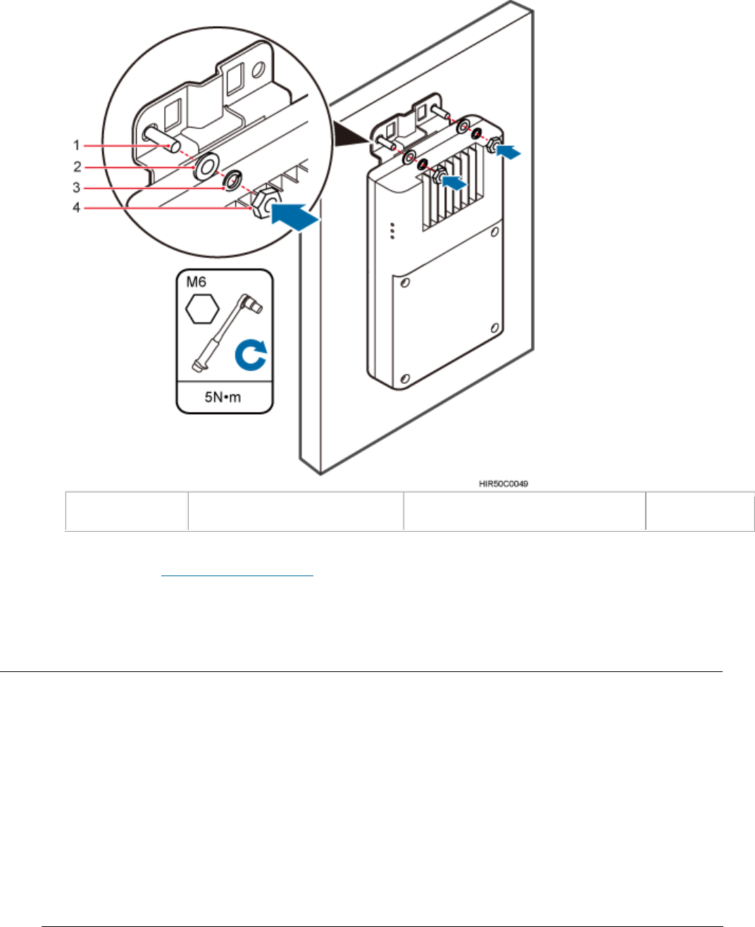
Issue 01 (2017-05-10)
Huawei Proprietary and Confidential
Copyright © Huawei Technologies Co., Ltd.
93
Figure 4 Fitting the Dock onto the wall
(1) Bolt
(2) Flat washer
(3) Spring washer
(4) Nut
Parent topic: (Optional) Installing a Dock
4.1.8.2 (Optional) Installing the PSE
This section describes the procedure and precautions for installing the PSE on a
wall.
Context
The PSE can be installed only on an indoor wall.
Procedure
1. Place the PSE against the wall, level it in the installation position, and
mark anchor points.
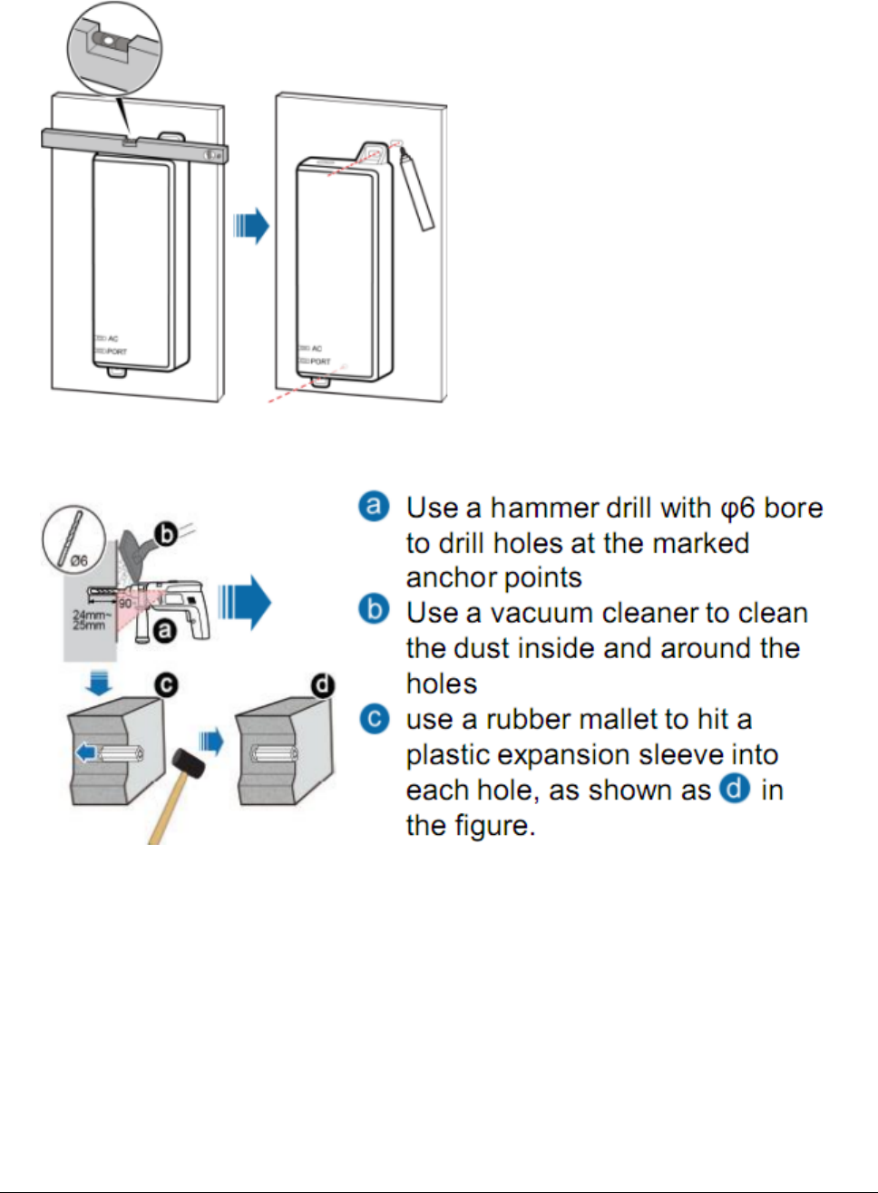
Issue 01 (2017-05-10)
Huawei Proprietary and Confidential
Copyright © Huawei Technologies Co., Ltd.
94
Figure 1 Marking anchor points
2. Drill holes and install expansion bolts.
Figure 2 Drill holes and install expansion bolts
3. Install the PSE
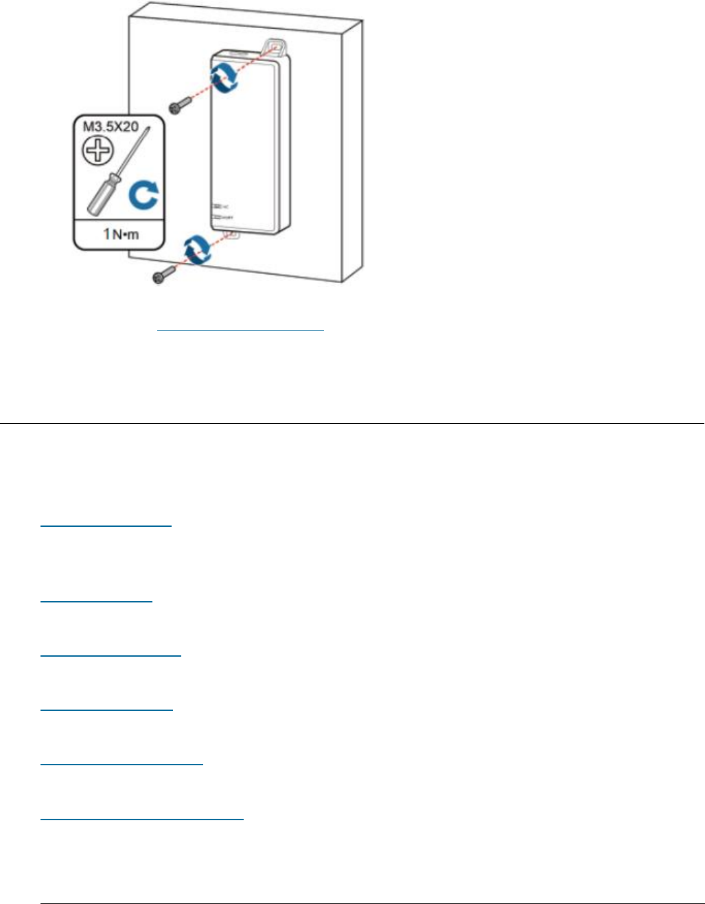
Issue 01 (2017-05-10)
Huawei Proprietary and Confidential
Copyright © Huawei Technologies Co., Ltd.
95
Figure 3 Install the PSE
Parent topic: Installing the Auxiliary Devices
4.1.9 Installing Cables
This section describes the procedures for installing eAN3810A cables and
auxiliary devices cables.
Cabling Requirements
Cables must be laid out according to the specified cabling requirements to
prevent signal interference.
Cable Connections
This section describes eAN3810A cable connections.
Installing a PGND Cable
This section describes the procedure for installing a PGND cable.
Installing a RF Jumper
This section describes the procedure for installing an RF jumper.
Installing an Ethernet Cable
This section describes how to install an Ethernet cable.
(Optional) Installing the PSE Cable
This section describes the procedure and precautions for installing the PSE
cables.
Issue 01 (2017-05-10)
Huawei Proprietary and Confidential
Copyright © Huawei Technologies Co., Ltd.
96
(Optional) Installing the Dock Ethernet Cable
This section describes procedure and precautions for installing a Dock Ethernet
cable.
(Optional) Installing the Dock Power Cable
This section describes the procedure and precautions for installing a power
cable. A Dock input power cable connects the Dock and an external power supply
device to lead external power into the Dock. A Dock cascading power cable is
used for power supply cascading between two Docks.
Parent topic: eAN3810A Hardware Installation Guide
4.1.9.1 Cabling Requirements
Cables must be laid out according to the specified cabling requirements to
prevent signal interference.
NOTE:
If a cable listed below is not required, skip the cabling requirements of the cable.
General Cabling Requirements
Bending radius requirements
The bending radius of a 7/8'' feeder must be greater than 250 mm (9.84 in.),
and the bending radius of a 5/4'' feeder must be greater than 380 mm (14.96
in.).
The bending radius of a 1/4'' jumper must be greater than 35 mm (1.38 in.).
The bending radius of a super-flexible 1/2'' jumper must be greater than 50
mm (1.97 in.), and the bending radius of an ordinary 1/2'' jumper must be
greater than 127 mm (5.00 in.).
The bending radius of a PGND cable must be at least three times its diameter.
The bending radius of a signal cable must be at least five times its diameter.
Cable binding requirements
Cables of the same type must be bound together.
Different types of cables must be separately laid out and bound, with a
minimum distance of 30 mm (1.18 in.) from each other.

Issue 01 (2017-05-10)
Huawei Proprietary and Confidential
Copyright © Huawei Technologies Co., Ltd.
97
Cables must be bound tightly and neatly. The sheaths of cables must not be
damaged.
Cable ties must face the same direction, and those at the same horizontal
line must be in a straight line.
The excess of indoor cable ties must be cut off. The excess of 5 mm (0.197
in.) of outdoor cable ties should be reserved, and the cut surfaces must be
smooth without sharp edges.
After cables are installed, labels or nameplates must be attached to the
cables at their ends, curves, and interconnection positions.
Security requirements
When laying out cables, avoid sharp objects, for example sharp edges on the
wall. If necessary, use tubes to protect the cables.
When laying out cables, keep cables away from heat sources, or use heat
insulation materials to insulate the cables from the heat sources.
Reserve a proper distance (0.1 m [3.937 in.] is recommended) between
equipment and cables especially at the cable curves to protect the cables and
equipment.
Indoor cabling requirements
Route each cable into the room through the feeder window.
Reserve drip loops for all cables outside the feeder window before routing
them into the room. Ensure that the radiuses of the drip loops are greater
than or equal to the minimum bending radiuses of the cables.
When routing a cable into the room, ensure that a person is assisting you in
the room.
Apply waterproof treatment to the feeder window.
Outdoor Cabling Requirements
Protect outdoor cables against potential damage. For example, thread the
cables through tubes.
Cables to be protected include AC power cables, transmission cables, and
cables laid out underground.
Use cable clips to secure cables outdoors.
Arrange cables neatly along the routing direction and use cable clips to
secure the cables.

Issue 01 (2017-05-10)
Huawei Proprietary and Confidential
Copyright © Huawei Technologies Co., Ltd.
98
Determine the positions where the clips are installed according to the actual
situation. For example, 7/8" feeders are secured with clips at an interval of
1.5 m (4.92 ft) to 2 m (6.56 ft), and CPRI fiber optic cables and power
cables are secured with clips at an interval of 1 m (3.28 ft) to 1.5 m (4.92
ft). Ensure that the clips are evenly spaced and in the same direction.
When fastening cables with a clip, ensure that the cables are aligned neatly
and are routed through the holes in the clip. Do not stretch the cables too
tightly.
When using clips to secure cables, tighten the screws on the clips after all
cables are arranged and laid out.
Special Cabling Requirements
Cabling of PGND cables
PGND cables for a base station must be connected to the same ground bar.
PGND cables must be buried in the ground or routed indoors.
The external conductor of the coaxial wire and the shield layer of the
shielded cable must have proper electrical contact with the metal surface of
the equipment which they are connected to.
PGND cables and signal cables must be installed separately. A certain
distance must be reserved between them to prevent interference from each
other.
Switches or fuses must not be installed on the PGND cables.
Other devices must not be used for electrical connections of the PGND cables.
All the metal parts in the housing of the equipment must be reliably
connected to the ground terminal.
Parent topic: Installing Cables
4.1.9.2 Cable Connections
This section describes eAN3810A cable connections.
Figure 1 shows the cable connections when an eAN3810A is installed.
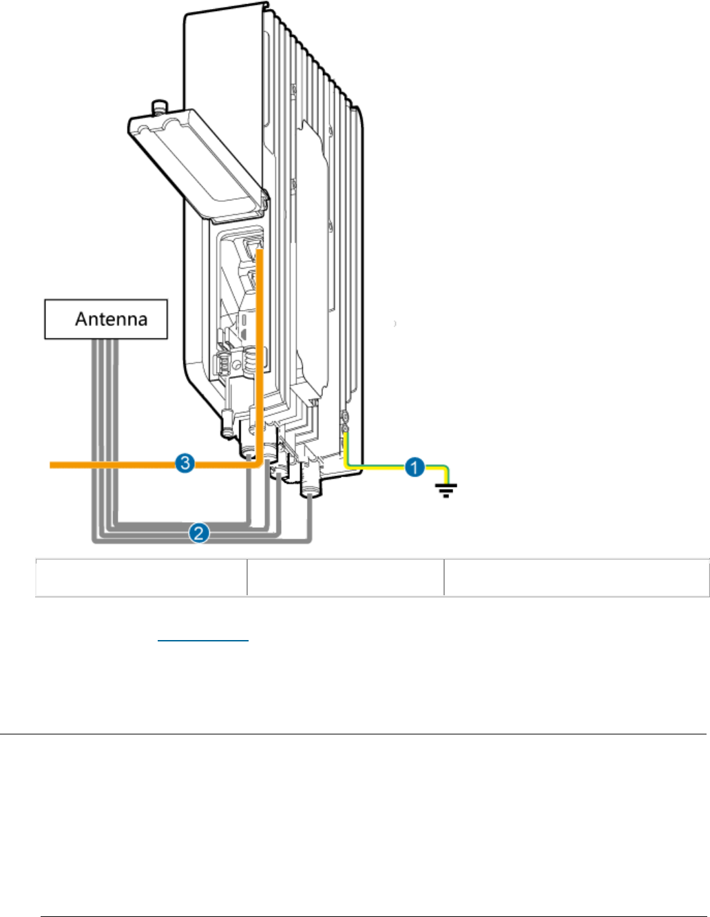
Issue 01 (2017-05-10)
Huawei Proprietary and Confidential
Copyright © Huawei Technologies Co., Ltd.
99
Figure 1 Cable connections when an eAN3810A is installed
(1) PGND cable
(2) RF jumper
(3) Ethernet cable
Parent topic: Installing Cables
4.1.9.3 Installing a PGND Cable
This section describes the procedure for installing a PGND cable.
Procedure
1. Prepare a eAN3810A PGND cable.
a. Cut the cable to a length suitable for the actual cable route.
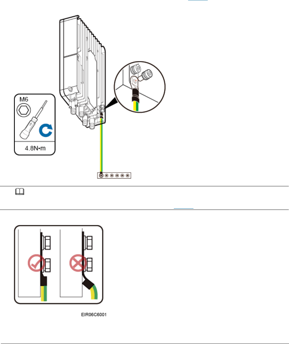
Issue 01 (2017-05-10)
Huawei Proprietary and Confidential
Copyright © Huawei Technologies Co., Ltd.
100
b. Add OT terminals to both ends of the cable.
2. Install the eAN3810A PGND cable.
Connect one end of the PGND cable with an M6 OT terminal to the ground
terminal at the eAN3810A bottom and the other end of the cable with an M8 OT
terminal to the external ground bar, as shown in Figure 1.
Figure 1 Installing a eAN3810A PGND cable
NOTE:
Crimp OT terminals in correct directions, as shown in Figure 2.
Figure 2 Correct direction for crimping an OT terminal
3. Label the installed cable.
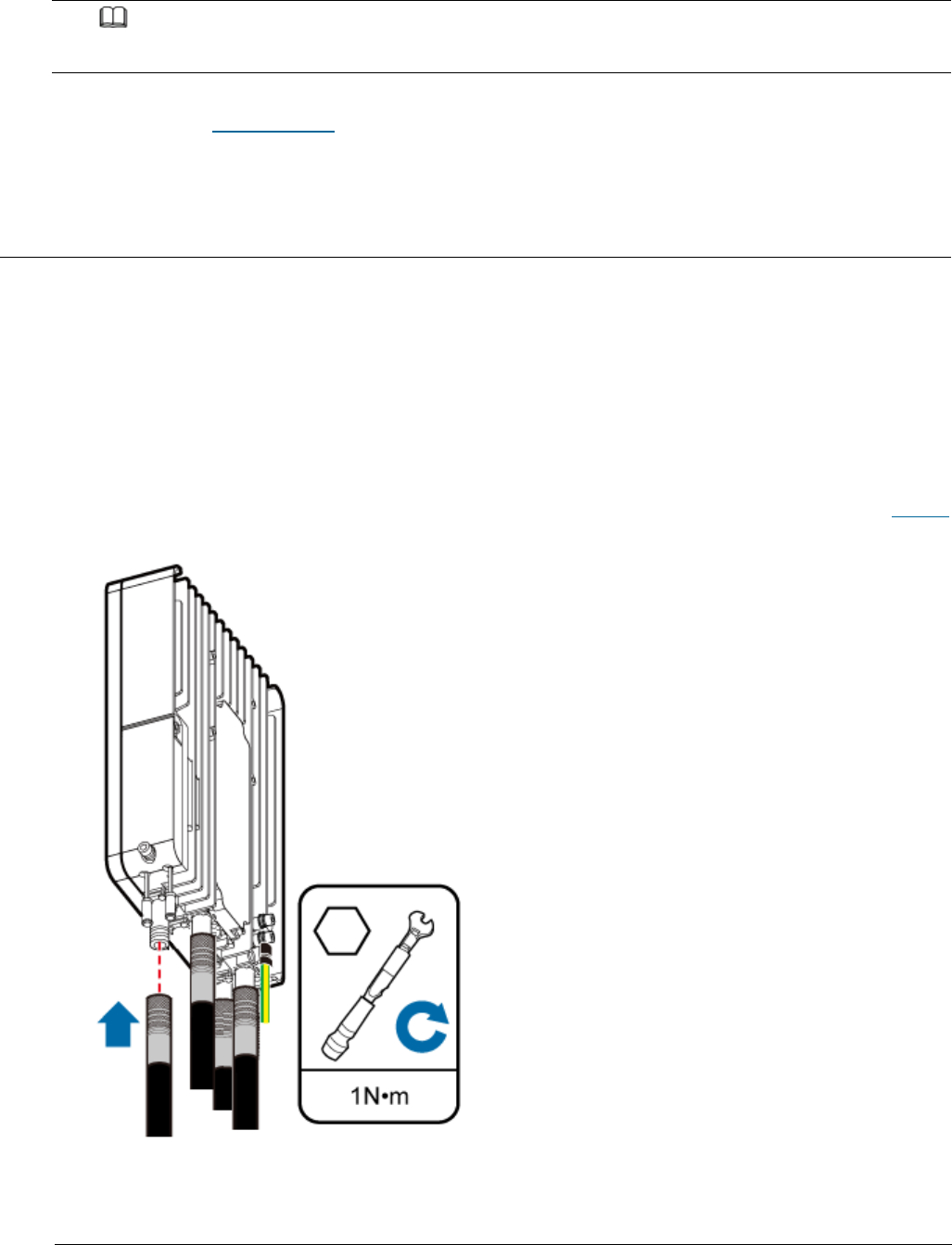
Issue 01 (2017-05-10)
Huawei Proprietary and Confidential
Copyright © Huawei Technologies Co., Ltd.
101
NOTE:
Follow the same procedure when installing a Dock PGND cable.
Parent topic: Installing Cables
4.1.9.4 Installing a RF Jumper
This section describes the procedure for installing an RF jumper.
Procedure
1. Remove the dustproof cap from the ANT port to be used on the eAN3810A.
2. Connect the type N male connector at one end of the eAN3810A RF jumper to
the ANT port at the bottom of the eAN3810A in sequence, and use a torque
wrench to tighten the connector to 1 N·m (8.85 lbf·in.), as shown in Figure1.
Figure 1 Installing an RF jumper
3. Connect the other end of the eAN3810A RF jumper to the external antenna
system.
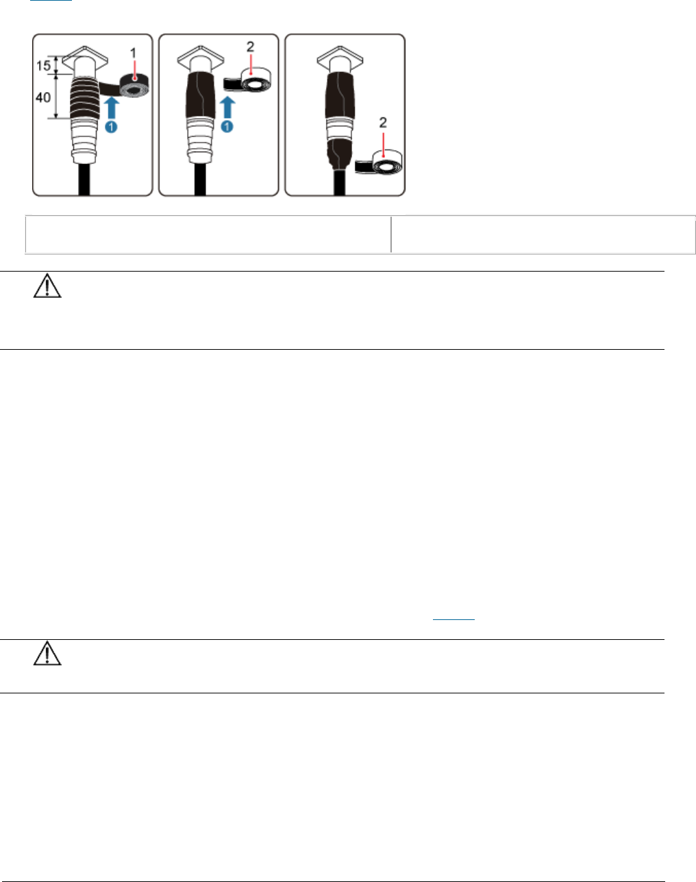
Issue 01 (2017-05-10)
Huawei Proprietary and Confidential
Copyright © Huawei Technologies Co., Ltd.
102
4. Waterproof the connector of the RF jumper by Waterproof tape, as shown in
Figure2.
Figure 2 Waterproof the connector of the RF jumper by waterproof tape
(1) PVC insulation tape
(2) Waterproof tape
NOTICE:
During installation, ensure that no foreign substance, including sand,
enters the waterproof tape.
b. Wrap a PVC insulation tape around the exposed area of the connector. The
wrapped area is 15 mm away from the end of the connector, with a total
length of 40 mm.
c. Ensure that dimensions (L x W) of the waterproof tape is 50 mm x 50 mm.
Stretch the tape horizontally until it is twice of the original length
and wrap it around the upper area of the connector.
Ensure that the upper end of the waterproof tape overlays that of the PVC
insulation tape.
Check the dustproof caps on antenna connectors. In outdoor scenarios,
dustproof caps must be waterproofed, as shown in Figure3.
NOTICE:
Do not remove dustproof caps from vacant antenna connectors.
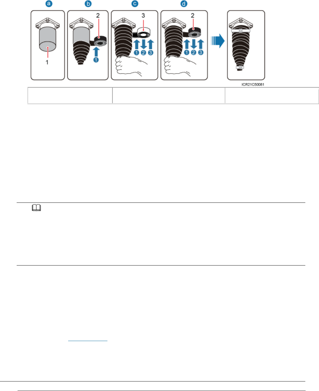
Issue 01 (2017-05-10)
Huawei Proprietary and Confidential
Copyright © Huawei Technologies Co., Ltd.
103
Figure 3 Waterproofing a dustproof cap
(1) Dustproof cap
(2) PVC insulation tape
(3) Waterproof tape
. Verify that dustproof caps are not removed.
a. Wrap one layer of PVC insulation tape on each connector from bottom up.
b. Wrap three layers of waterproof tape on each connector, first from bottom
up, then from top down, and finally from bottom up. Wrap each layer of
the tape around the connector tightly.
c. Wrap three layers of PVC insulation tape on each connector, first from
bottom up, then from top down, and finally from bottom up. Wrap each
layer of the tape around the connector tightly.
NOTE:
When wrapping waterproof tape, stretch the tape evenly until it is twice of the original
length. When wrapping PVC insulation tape, do not stretch it.
Wrap each layer of tape around each connector tightly and neatly, and ensure that the
adhesive surface of each layer of tape overlaps more than 50% of the lower layer.
When cutting off a cable tie, reserve a surplus length of 3 mm (0.12 in.) to 5 mm (0.20
in.).
Follow-up Procedure
1. Route the cable by following the instructions in section cabling
requirements and use cable ties to bind the cable.
2. Label the installed cable.
Parent topic: Installing Cables
4.1.9.5 Installing an Ethernet Cable

Issue 01 (2017-05-10)
Huawei Proprietary and Confidential
Copyright © Huawei Technologies Co., Ltd.
104
This section describes how to install an Ethernet cable.
Context
The Ethernet cable must be of Category 5e (enhanced) or higher. In addition,
its cross-sectional area must be 24 AWG or larger and frame spread rating
must be CM or higher.
Both the cable and the RJ45 connectors are delivered, and they must be
assembled onsite. You need to use a network cable tester to test the Ethernet
cable connection.
With the internal PoE module providing power, the maximum length of an
Ethernet cable is 100 m.
Procedure
1. Make the Ethernet cables.
a. Assemble an RJ45 connector and an Ethernet cable.
b. Check whether the made RJ45 connector is qualified.
c. To complete the assembly of the other end, repeat 1.a and 1.b.
d. Check whether the touch points on the connectors at both ends are
normally conducted and well contacted and whether the connections are
correct.
2. Connect the RJ45 connector at one end of the Ethernet cable to the PoE port
on the eAN3810A panel, and push the cables into the cable clips, as shown in
Figure 1.
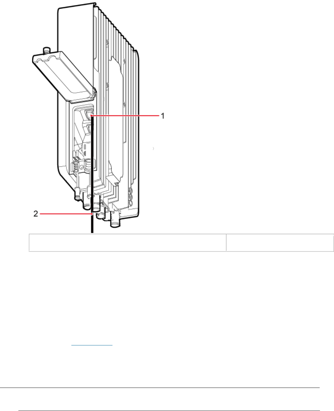
Issue 01 (2017-05-10)
Huawei Proprietary and Confidential
Copyright © Huawei Technologies Co., Ltd.
105
Figure 1 Installing an eAN3810A Ethernet cable
(1) PoE port on the eAN3810A panel
(2) Ethernet cable
3. Connect the RJ45 connector at the other end of the Ethernet cable to
auxiliary devices port.
Follow-up Procedure
1. Route the cable, and then use a cable tie to bind the cable.
2. Label the installed cable.
Parent topic: Installing Cables
4.1.9.6 (Optional) Installing the PSE Cable
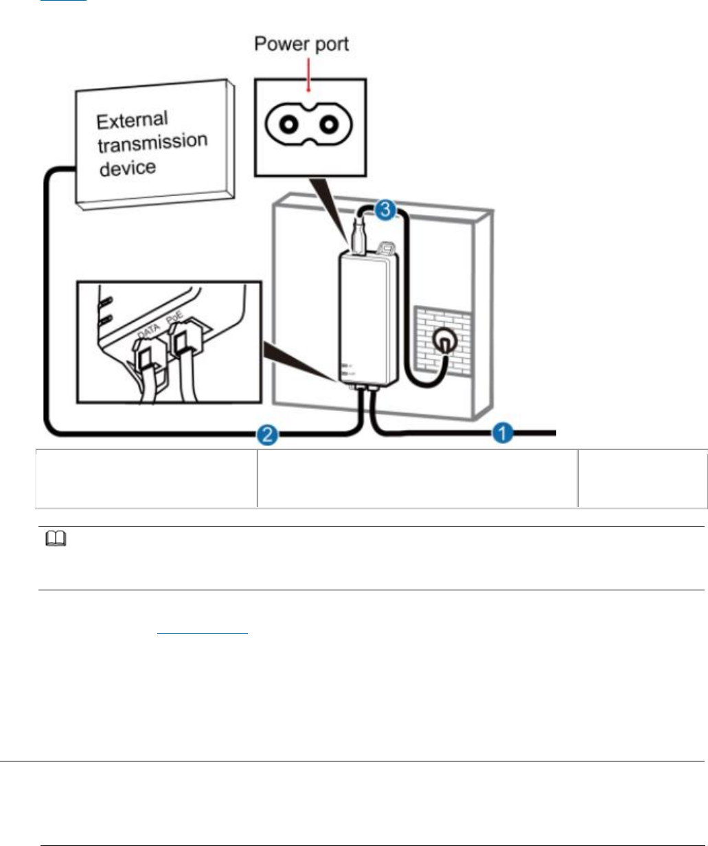
Issue 01 (2017-05-10)
Huawei Proprietary and Confidential
Copyright © Huawei Technologies Co., Ltd.
106
This section describes the procedure and precautions for installing the PSE
cables.
Figure 1 shows the cable connections when the PSE is installed.
Figure 1 Installing the PSE Cable
(1) Ethernet cable
between eAN3810A and PSE
(2) Ethernet cable between PSE and
External transmission device
(3) PSE Power
cable (2m)
NOTE:
The total length of cables connected between the eAN3810A, PSE, and external transmission device
does not exceed 100 m.
Parent topic: Installing Cables
4.1.9.7 (Optional) Installing the Dock Ethernet
Cable
This section describes procedure and precautions for installing a Dock Ethernet
cable.
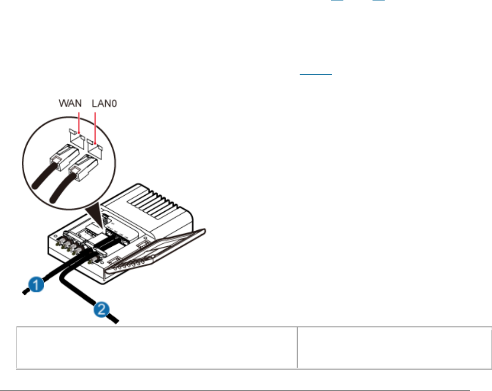
Issue 01 (2017-05-10)
Huawei Proprietary and Confidential
Copyright © Huawei Technologies Co., Ltd.
107
Context
The Ethernet cable must be of Category 5e (enhanced) or higher. In addition,
its cross-sectional area must be 24 AWG or larger and frame spread rating
must be CM or higher.
Ethernet cables are not delivered, and they must be prepared onsite. You need
to use a network cable tester to test the Ethernet cable connection.
With the internal PoE module providing power, the maximum length of an
Ethernet cable is 100 m.
Procedure
1. Make the Ethernet cables.
a. Assemble an RJ45 connector and an Ethernet cable.
b. Check whether the made RJ45 connector is qualified.
c. To complete the assembly of the other end, repeat 1.a and 1.b.
d. Check whether the touch points on the connectors at both ends are
normally conducted and well contacted and whether the connections are
correct.
2. Installing the Dock Ethernet cable, as shown in Figure 1.
Figure 1 Installing the Dock Ethernet cable
(1) Ethernet cable between Dock and external
transmission device
(2) Ethernet cable between
eAN3810A and Dock

Issue 01 (2017-05-10)
Huawei Proprietary and Confidential
Copyright © Huawei Technologies Co., Ltd.
108
a. Connect one end of the assembled Ethernet cable to the WAN port in the
cabling cavity of the Dock and the other end to the external transmission
device.
b. Connect the other end of the Ethernet cable, which is connected to the
PoE port on the eAN3810A, to the LAN0 port in the cabling cavity of the
Dock.
NOTICE:
The eAN3810A must be connected to the LAN0 port on the Dock. Otherwise,
you are not able to maintain the eAN3810A remotely.
Parent topic: Installing Cables
4.1.9.8 (Optional) Installing the Dock Power
Cable
This section describes the procedure and precautions for installing a power
cable. A Dock input power cable connects the Dock and an external power supply
device to lead external power into the Dock. A Dock cascading power cable is
used for power supply cascading between two Docks.
Context
Table 1 lists the specifications of the two power cables.
Table 1 Power cable specifications
Cable
Color
One End
The Other End
Dock input power
cable
L
Brown
Cord end
terminal (1.5
mm2)
Depends on the
external power
device
N
Blue
Cord end
terminal (1.5
mm2)
Depends on the
external power
device
PE
Yellow and green
Cord end
terminal (1.5
Depends on the
external power
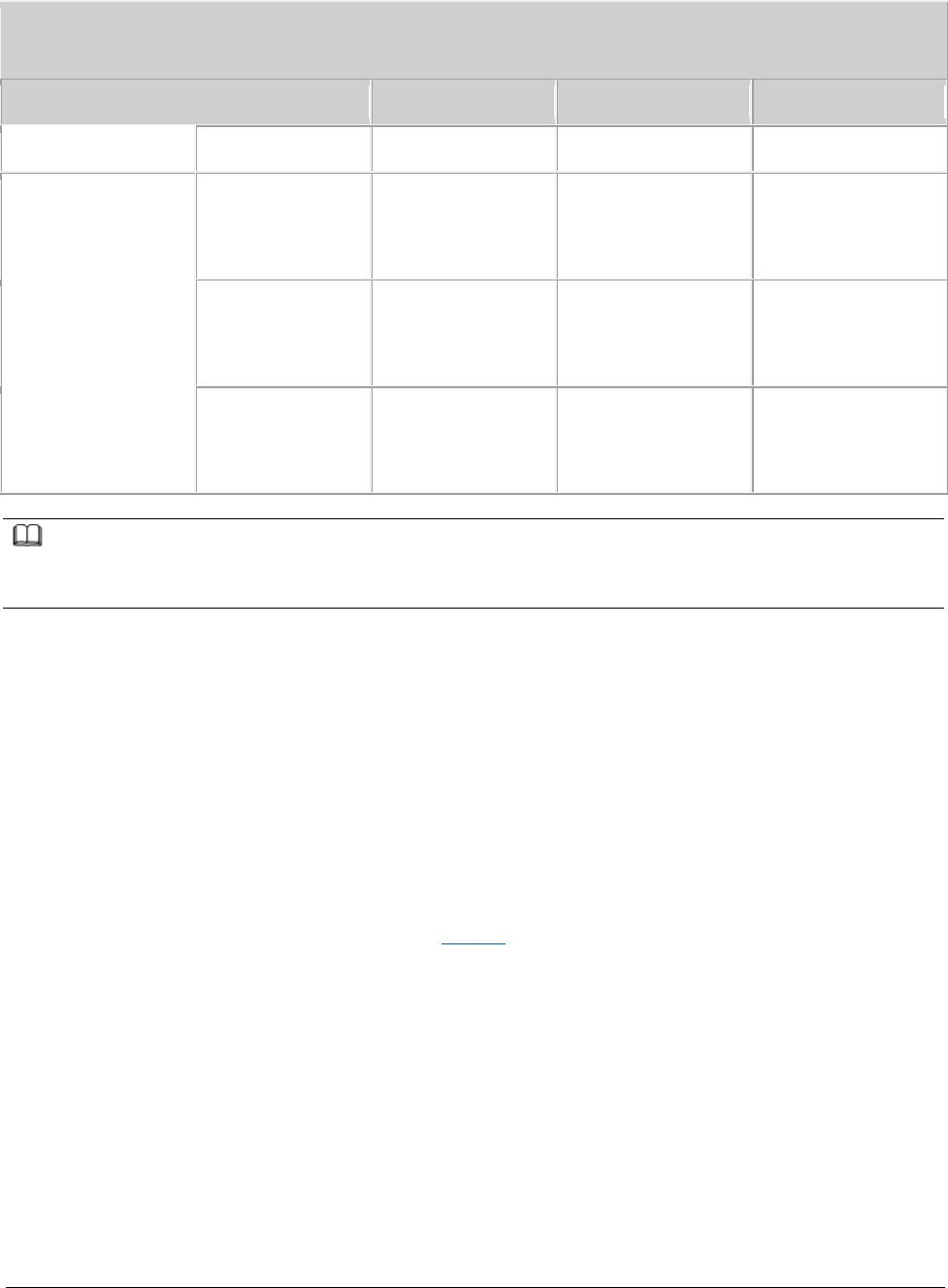
Issue 01 (2017-05-10)
Huawei Proprietary and Confidential
Copyright © Huawei Technologies Co., Ltd.
109
Table 1 Power cable specifications
Cable
Color
One End
The Other End
mm2)
device
Dock cascading
power cable
L
Brown
Cord end
terminal (1.5
mm2)
Cord end
terminal (1.5
mm2)
N
Blue
Cord end
terminal (1.5
mm2)
Cord end
terminal (1.5
mm2)
PE
Yellow and green
Cord end
terminal (1.5
mm2)
Cord end
terminal (1.5
mm2)
NOTE:
The color and structure of the power cables differ in different countries and regions. The power
cables purchased locally must conform to the local standards.
Procedure
1. Make power cables.
a. Cut the cable to a length suitable for the actual cable route.
b. Add an OT terminal to one end of the cable, and add the corresponding
power terminal to the other end according to external power supply device.
c. Optional: Add an OT terminal to each end of the Dock cascading power
cable.
2. Install power cables, as shown in Figure 1.
a. Open the protective cover of the power supply terminal.
b. Install Dock input power cables.
Use a flat-head screwdriver to loosen the left ports on the L, N, and PE
wiring posts inside the Dock. Connect one end of each cable to the
corresponding port on the left side and tighten the wiring posts. Connect
the other end to external devices.
c. Optional: Install Dock cascading power cables.
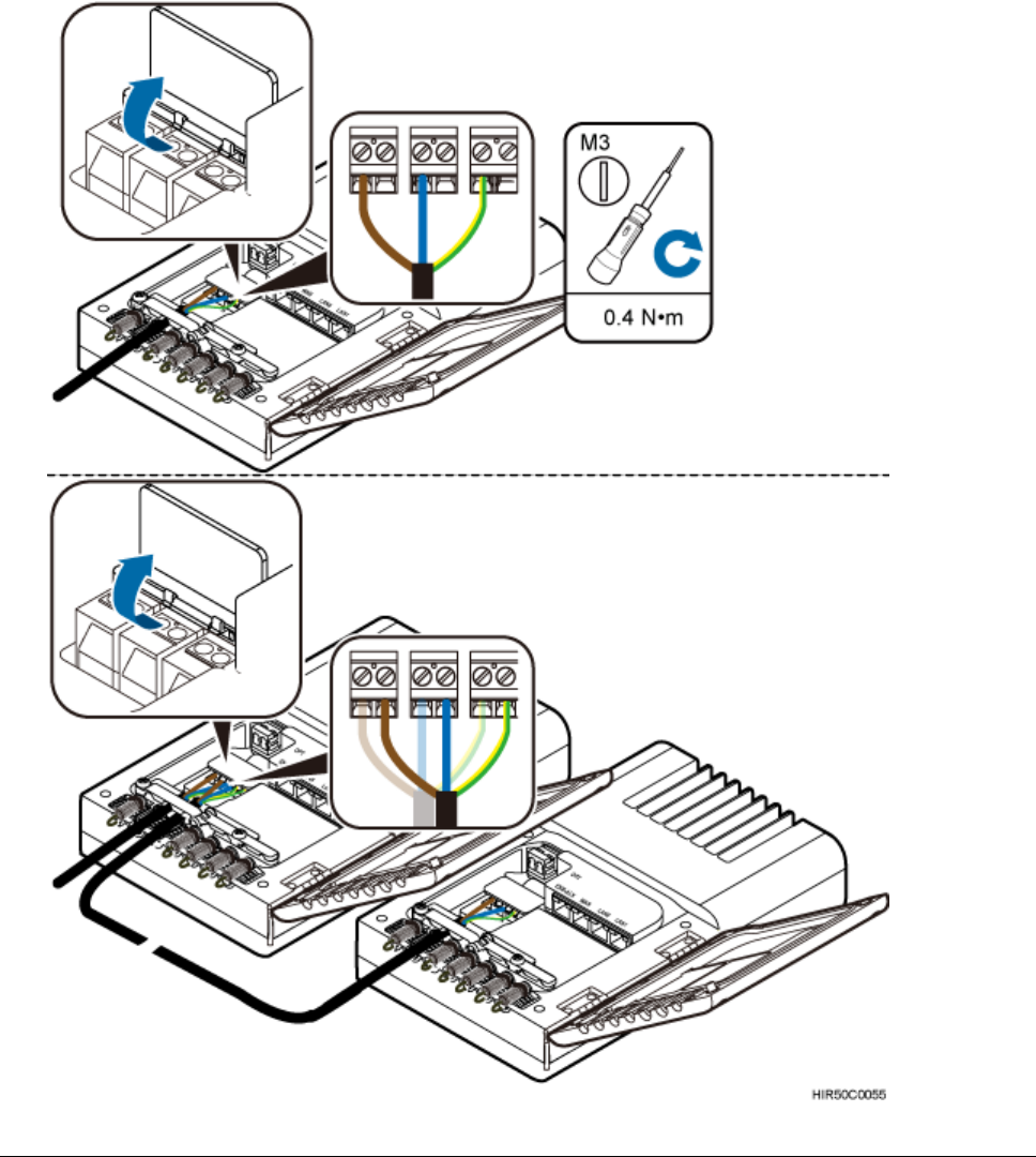
Issue 01 (2017-05-10)
Huawei Proprietary and Confidential
Copyright © Huawei Technologies Co., Ltd.
110
Use a flat-head screwdriver to loosen the right ports on the L, N, and PE
wiring posts inside one Dock. Connect one end of each cable to the
corresponding port on the right side and tighten the wiring posts.
Connect the other end of cables to corresponding ports on the L, N, or PE
wiring posts inside the lower-level cascaded Dock.
d. Restore the protective cover of the power supply terminal.
Figure 1 Installing power cables
Issue 01 (2017-05-10)
Huawei Proprietary and Confidential
Copyright © Huawei Technologies Co., Ltd.
111
NOTICE:
The protective cover of the power supply terminal is automatically secured.
After the procedure is complete, tap the protective cover to restore it.
Parent topic: Installing Cables
4.1.10 Checking Hardware Installation
eAN3810A hardware installation checking includes hardware and cable installation
checking.
Table 1 lists the hardware installation checking items.
Table 1 Hardware installation checking list
No.
Item
1
The installation position of each device strictly complies with
the engineering design and meets clearance requirements.
Sufficient space is reserved for equipment maintenance.
2
The eAN3810A is securely installed.
3
The cover plate is securely installed on the eAN3810A cabling
cavity.
4
Waterproof blocks are securely installed in vacant cable troughs
of the eAN3810A cabling cavity, and the cover plate of the
cabling cavity is securely installed. In addition, vacant RF
ports are covered with dustproof caps and the caps are tightened.
5
Labels are correct, legible, and complete at both ends of each
cable, feeder, and jumper.
Table 2 lists the check items of the signal cable connection.
Table 2 Checklist for the signal cable connection
No.
Item

Issue 01 (2017-05-10)
Huawei Proprietary and Confidential
Copyright © Huawei Technologies Co., Ltd.
112
Table 2 Checklist for the signal cable connection
No.
Item
1
The connectors of the signal cables must securely connected.
2
The connectors of the signal cables are intact.
3
The signal cables are intact.
4
The cable ties are evenly spaced. The signal cables are bound
neatly with cable ties to proper tightness, and arranged at even
intervals in the same direction.
5
The extra length of the cable ties is cut and removed. The cut
surfaces of the indoor cables are smooth and have no sharp edges.
6
The cable layout facilitates maintenance and expansion.
7
Correct and clear labels are attached to both ends of the signal
cables.
Table 3 lists the checking items for other cable connections.
Table 3 Checklist for other cable connections
No.
Item
1
The connectors of the other cables must securely connected.
2
Labels on the cables are legible and bound based on the
engineering requirements. The cables must be bound tightly and
neatly. The sheaths of the cables must not be damaged.
3
Positions for routing the cables must meet requirements of the
engineering design.
4
There are no connectors or joints on each PGND cable. None of
PGND cables can be short-circuited or reversely connected. In
addition, these cables are not damaged or broken.
5
PGND cables are separately bound from other cables.
6
The protection grounding of the eAN3810A and the surge protection
grounding of the building share one group of ground conductors.
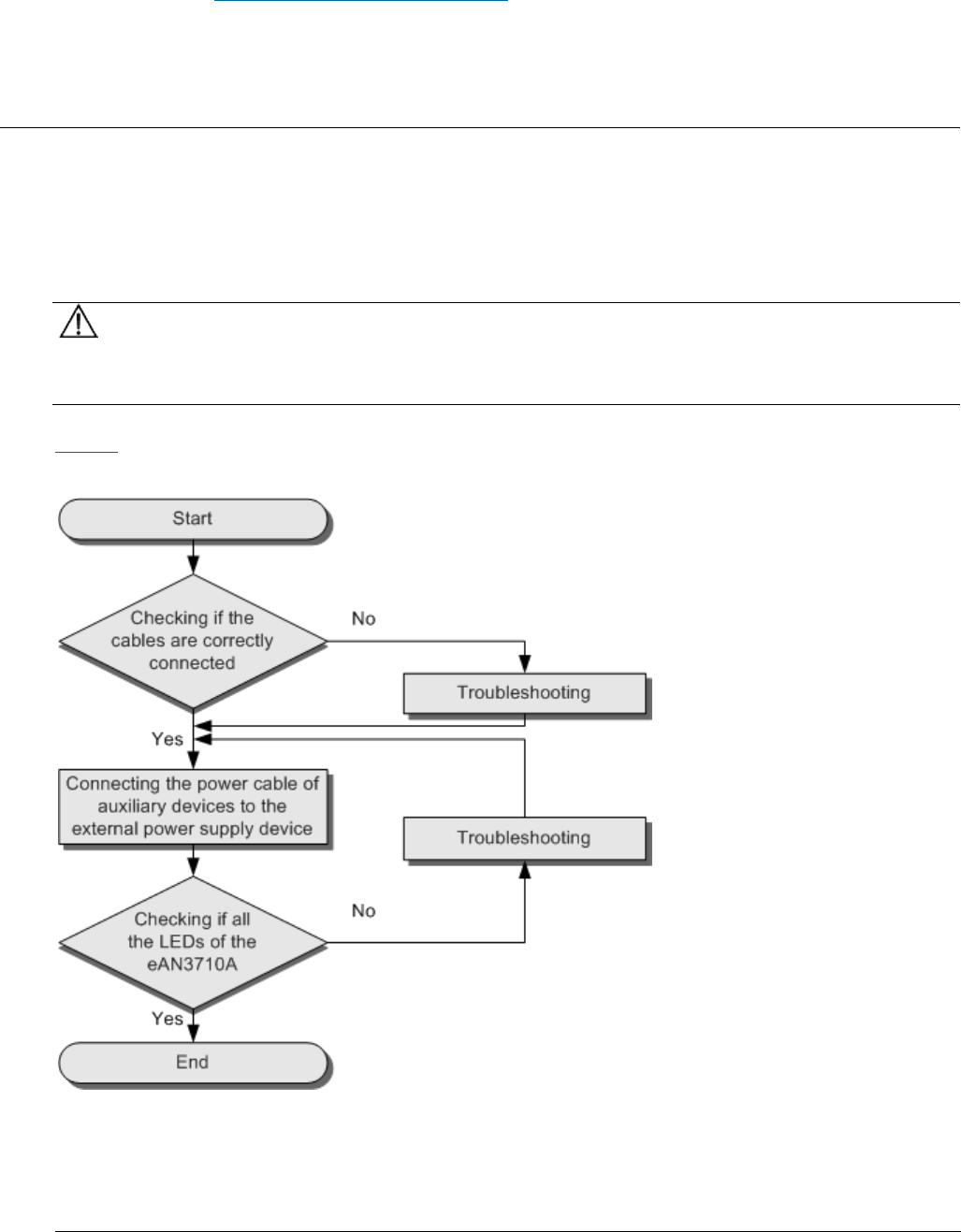
Issue 01 (2017-05-10)
Huawei Proprietary and Confidential
Copyright © Huawei Technologies Co., Ltd.
113
Parent topic: eAN3810A Hardware Installation Guide
4.1.11 Power-On Check on the eAN3810A
This section describes the procedure for performing a power-on check on the
eAN3810A.
eAN3810A Power-On Check Procedure
NOTICE:
After you unpack a eAN3810A, you must power on it within 24 hours. If you power
off the eAN3810A for maintenance, you must restore power to it within 24 hours.
Figure 1 shows the eAN3810A power-on check procedure.
Figure 1 Power-on check procedure
Checking the Indicator Status
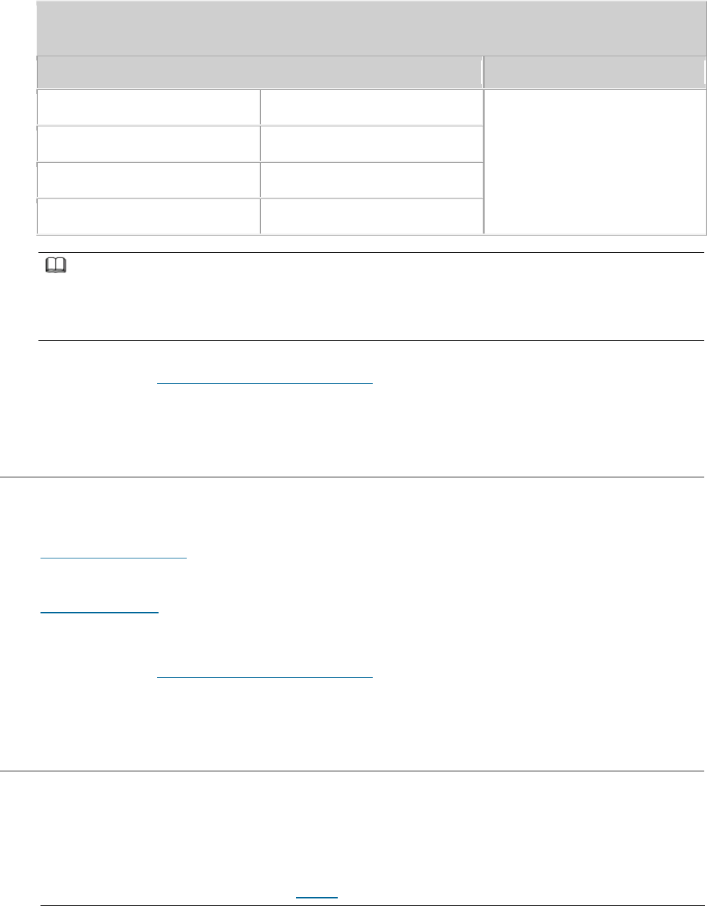
Issue 01 (2017-05-10)
Huawei Proprietary and Confidential
Copyright © Huawei Technologies Co., Ltd.
114
Table 1 Checking the indicator status
If...
then...
RUN
Steady white
The eAN3810A is running
correctly.
ETH
Blinking white
WIFI
Off
LINK
Off
NOTE:
During the eAN3810A startup, there is no need to observe the indicator status.
During a start, the eAN3810A reads and writes the flash and therefore the indicators blinking
quickly may blink irregularly for 1-2 seconds, which does not affect services.
Parent topic: eAN3810A Hardware Installation Guide
4.1.12 Appendix
This section describes reference information during installation.
ESN Collection Template
This section describes the eAN3810A ESN collection template.
Antenna Installation
This section describes the reference documents for installing the antenna system.
Parent topic: eAN3810A Hardware Installation Guide
4.1.12.1 ESN Collection Template
This section describes the eAN3810A ESN collection template.
The ESN collection template is used to record the installation position, and ESN
of the site at the initial installation stage to facilitate subsequent
commissioning and maintenance. Table 1 shows the ESN collection template.
Issue 01 (2017-05-10)
Huawei Proprietary and Confidential
Copyright © Huawei Technologies Co., Ltd.
115
Table 1 ESN collection template
No.
Site Number
Site Name
Base Station ESN
Location
Information
Sample
xx
eAN_1
xx floor, xx
building, xx
mansion
Note: The ESN collection template is essential to the engineering stage and subsequent
maintenance, especially when multiple devices are installed at a short distance. This
is because the template defines the radio network to access. Please maintain this
template with caution.
Parent topic: Appendix
4.1.12.2 Antenna Installation
This section describes the reference documents for installing the antenna system.
Related Document
Description
Antenna System (on Tower) Quick Installation Guide
This document describes the installation
procedure and manhour requirements of the
antenna system.
Antenna System (on Roof Pole) Quick Installation Guide
This document describes the installation
procedures and methods of the antenna
system on roof pole.
Issue 01 (2017-05-10)
Huawei Proprietary and Confidential
Copyright © Huawei Technologies Co., Ltd.
116
Related Document
Description
GPS Satellite Antenna System Quick Installation Guide
This document describes the installation
procedures and methods of the GPS antenna
system.
Parent topic: Appendix
4.2 eAN3810A Deployment Guide
Overview
This document describes how to use the CME and U2000 to configure data for
eAN3810A and to commission and verify configured eAN3810A based on design
requirements. This document applies to the initial stage of cellular network
deployment.
Product Version
NOTE:
Unless otherwise stated, "eNodeB", "Pico", "eAN", and "AirNode" in this document refer to the
3810 series AirNode.
The 3810 series AirNode is a base station that provides communications services
in Huawei OneAir solution. The following table lists the product name and
product version related to the 3810 series AirNode.
Product Name
Product Version
eAN3810A
V100R001C00
Intended Audience
This document is intended for:
Network planning engineers
Network operators
System engineers

Issue 01 (2017-05-10)
Huawei Proprietary and Confidential
Copyright © Huawei Technologies Co., Ltd.
117
Organization
MicroSD Card Site Deployment
MML Site Deployment
Parent topic: Installation and commissioning
4.2.1 MicroSD Card Site Deployment
Introduction to Deployment Modes
Deployment Preparation
This section describes the data and files to be prepared for eAN3810A deployment.
Hardware installation check phase
Engineering Verification
This section describes how to complete the eAN3810A commissioning task, view
deployment results, and verify services.
FAQ
This section describes the graphical user interfaces (GUIs) involved in
deployment and troubleshooting methods for common problems.
Parent topic: eAN3810A Deployment Guide
4.2.1.1 Introduction to Deployment Modes
Site Deployment Overview
With site deployment, data is planned, delivered, and activated on a per pico
basis, and MicroSD card commissioning can be used.
Deployment Process
This section describes the eAN3810A site deployment process. Site deployment
requires cooperation of engineers at sites and the OMC, who must master the
deployment process shown in Figure 1 in advance of the deployment.
Parent topic: MicroSD Card Site Deployment
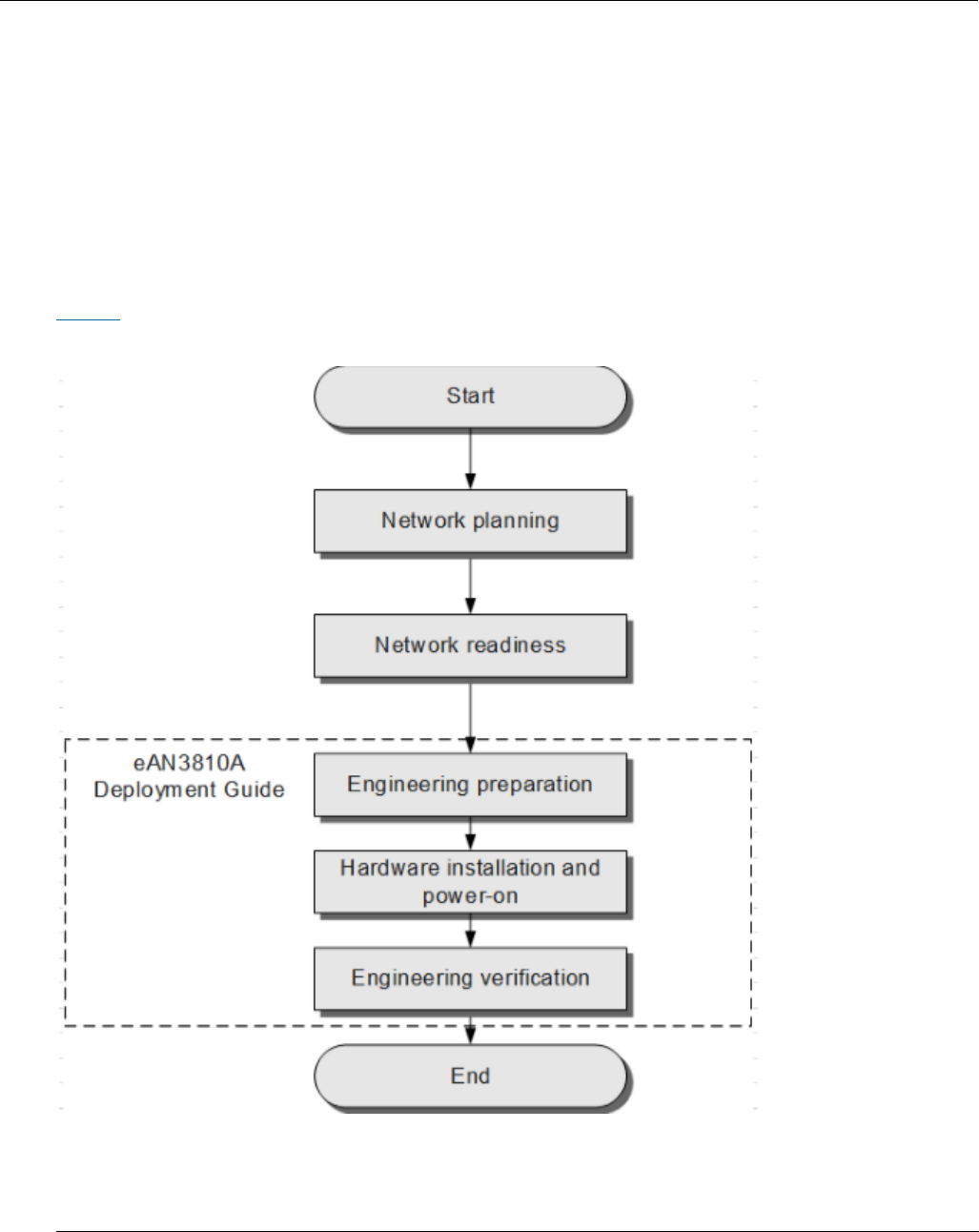
Issue 01 (2017-05-10)
Huawei Proprietary and Confidential
Copyright © Huawei Technologies Co., Ltd.
118
4.2.1.1.1 Site Deployment Overview
With site deployment, data is planned, delivered, and activated on a per pico
basis, and MicroSD card commissioning can be used.
Application Scenarios and Deployment Principles
Site deployment applies to outdoor coverage scenarios where operator-provided
private transport networks are used.
Scope
Figure 1 shows the procedures for site deployment in this document.
Figure 1 Site deployment in this document
1. Network planning: Plan deployment solutions based on network conditions.
These include: Networking solution, Transmission solution and Parameter
planning.

Issue 01 (2017-05-10)
Huawei Proprietary and Confidential
Copyright © Huawei Technologies Co., Ltd.
119
2. Network readiness: This is a prerequisite to Pico deployment. Specifically,
network readiness indicates that the core network, RNC, U2000, SeGW, CA
server, and clock server have been deployed and configured, and the
transport network is working properly.
3. Engineering preparation: Use the U2000 to prepare configuration data,
software packages, and commissioning licenses based on the network plan.At
the site, get ready service dialing tools.
4. Hardware installation and power-on: At the site, install and power on the
Pico and perform checks.
5. Engineering verification: Create, start, and monitor commissioning tasks,
query deployment results, and verify services.
Parent topic: Introduction to Deployment Modes
4.2.1.1.2 Deployment Process
This section describes the eAN3810A site deployment process. Site deployment
requires cooperation of engineers at sites and the OMC, who must master the
deployment process shown in Figure 1 in advance of the deployment.
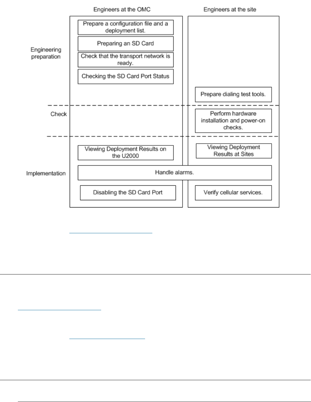
Issue 01 (2017-05-10)
Huawei Proprietary and Confidential
Copyright © Huawei Technologies Co., Ltd.
120
Figure 1 Site deployment process
Parent topic: Introduction to Deployment Modes
4.2.1.2 Deployment Preparation
This section describes the data and files to be prepared for eAN3810A deployment.
Preparation for Site Deployment
This section describes preparations for deployment.
Parent topic: MicroSD Card Site Deployment
4.2.1.2.1 Preparation for Site Deployment

Issue 01 (2017-05-10)
Huawei Proprietary and Confidential
Copyright © Huawei Technologies Co., Ltd.
121
This section describes preparations for deployment.
Preparing Common Base Station Deployment Data Files on the CME
This section describes how to prepare, verify, and export common base station
deployment data files on the CME.
Preparing an SD Card
This section describes how to prepare an SD card before loading the software
package and data configuration file onto a eAN3810A.
Checking a Transport Network
This section describes how to check a transport network. The transport network
affects the Automatic OMCH Establishment feature. Therefore, before
commissioning an eAN3810A,O&M engineers must check whether the OMCH networking
and the network equipment meet the configuration requirements of the
corresponding scenario.
Checking the SD Card Port Status
Preparing Dialing Test Tools
Dialing tests are performed by using test terminals to check whether deployed
eAN3810A can provide services properly. Prepare test terminals and ensure that
the test subscriber identity module (SIM) cards have registered with the Core
Network.
Parent topic: Deployment Preparation
4.2.1.2.1.1 Preparing Common Base Station
Deployment Data Files on the CME
This section describes how to prepare, verify, and export common base station
deployment data files on the CME.
Data Configuration Process
This section describes the data configuration process. Before configuring data,
you are advised to learn the initial base station configuration process on the
CME.
Data Preparation
Before starting configuration, prepare data for each eAN3810A based on the
network plan. The data to be prepared includes basic data, device data,
transport data, and radio data.

Issue 01 (2017-05-10)
Huawei Proprietary and Confidential
Copyright © Huawei Technologies Co., Ltd.
122
Creating a Work Area
The CME provides one current data area and allows users to create multiple
planned data areas. The current data area is used for synchronizing and saving
configuration data on the live network, and you can only view data in the
current data area. A planned data area is used for configuring data. Therefore,
you need to create a planned data area before configuring data.
Configuring Data on GUIs
This section describes how to initially configure a single base station on GUIs
using a default or user-defined template.
Verifying Data
This section describes how to verify the validity and integrity of base station
configuration data before you export the data. Validity verification is to check
whether base station configuration data meets NE configuration rules. If the
data does not meet the rules, it is not sent to NEs. Integrity verification is
to check whether base station configuration data is complete. If the data is
incomplete, services cannot be provided. For example, a base station without
cell data cannot provide radio services.
Exporting Configuration Files
Parent topic: Preparation for Site Deployment
4.2.1.2.1.1.1 Data Configuration Process
This section describes the data configuration process. Before configuring data,
you are advised to learn the initial base station configuration process on the
CME.
Figure 1 shows the data configuration process.
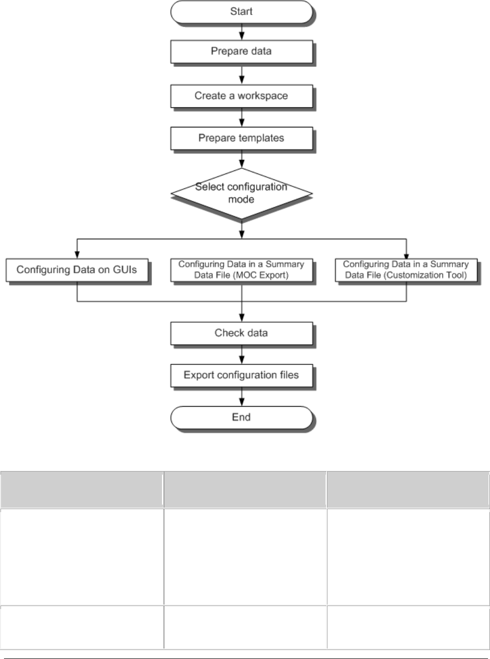
Issue 01 (2017-05-10)
Huawei Proprietary and Confidential
Copyright © Huawei Technologies Co., Ltd.
123
Figure 1 Data configuration process
Configuration methods are described as follows.
Base Station Creation Method
Scenario
Remarks
Wizard-based single base
station creation
No base station has been
deployed on the live network
or only a small number of
base stations need to be
deployed.
You can create base stations
using the base station
creation wizard on the CME.
Batch base station creation
using the tool for
A large number of base
stations need to be
You can obtain ranges of MOs
and parameters in the

Issue 01 (2017-05-10)
Huawei Proprietary and Confidential
Copyright © Huawei Technologies Co., Ltd.
124
Base Station Creation Method
Scenario
Remarks
customizing a summary data
file
deployed, and their planned
data differs greatly from
data of existing base
stations.
summary data file by
specifying MOCs in the MOC
list.
Batch base station creation
using the MOC Export
function to generate a
summary data file
A large number of base
stations need to be
deployed, and their planned
data is similar to data of
existing base stations.
You can obtain ranges of MOs
and parameters in the
summary data file by
customizing MOs and
parameters using the tool
for customizing a summary
data file.
Parent topic: Preparing Common Base Station Deployment Data Files on the CME
4.2.1.2.1.1.2 Data Preparation
Before starting configuration, prepare data for each eAN3810A based on the
network plan. The data to be prepared includes basic data, device data,
transport data, and radio data.
Select data preparation tables by scenario and prepare the data in the tables.
Table 1 describes scenario-specific data preparation tables .
Table 1 Scenario-specific data preparation tables
Scenario
Data Preparation Table (on the eAN3810A Side)
Non-secure transmission networking
Click Data Preparation in Non-secure
Transmission Networking to download the
table.
Data to be prepared on the eAN3810A side
for enabling cellular services includes
device data, common transport data, LTE
radio data.

Issue 01 (2017-05-10)
Huawei Proprietary and Confidential
Copyright © Huawei Technologies Co., Ltd.
125
Parent topic: Preparing Common Base Station Deployment Data Files on the CME
4.2.1.2.1.1.3 Creating a Work Area
The CME provides one current data area and allows users to create multiple
planned data areas. The current data area is used for synchronizing and saving
configuration data on the live network, and you can only view data in the
current data area. A planned data area is used for configuring data. Therefore,
you need to create a planned data area before configuring data.
Context
CME functions can be started in the following modes. Table 1describes the modes.
The navigation paths for starting CME functions are different in CME client mode
and U2000 client mode. For example, to enable the function of customizing a
summary data file on the CME, choose Advanced Customize Summary Data File (CME
client mode) or CME Advanced Customize Summary Data File (U2000 client mode) on
the menu bar.
Table 1 Startup modes
Startup Mode
Description
CME client mode
This mode applies when the CME functions are used. In this mode,
only the CME functions are started, and the U2000 functions are not
started, such as fault management, topology management, and
performance management.
In this mode, the CME functions can be started using either of the
following methods:
Starting the CME Client on the U2000 Client in Application Mode.
Starting the CME Client Directly.
U2000 client mode
This mode applies when both the CME and U2000 functions are used. In
this mode, both the CME functions and U2000 functions (such as fault
management, topology management, and performance management) are
started. For detailed operations, see Starting CME Functions on the
U2000 Client in Traditional Mode.
Procedure
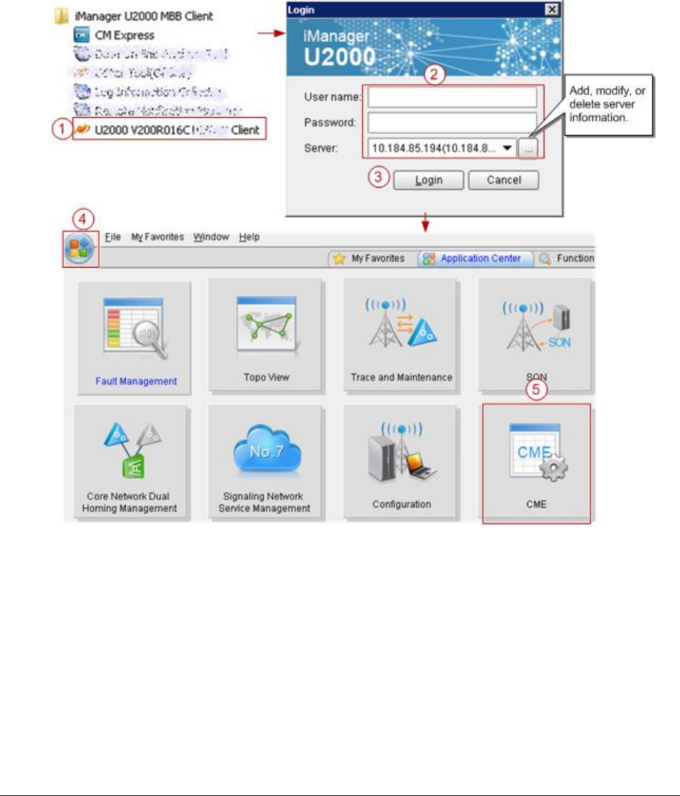
Issue 01 (2017-05-10)
Huawei Proprietary and Confidential
Copyright © Huawei Technologies Co., Ltd.
126
1. Start the CME.
Start CME functions on the U2000 client in application mode.
On the Windows desktop, choose Start All Programs iManager U2000 MBB
Client.
Start the CME client directly.
On the Windows desktop, choose Start All Programs iManager U2000 MBB
Client.
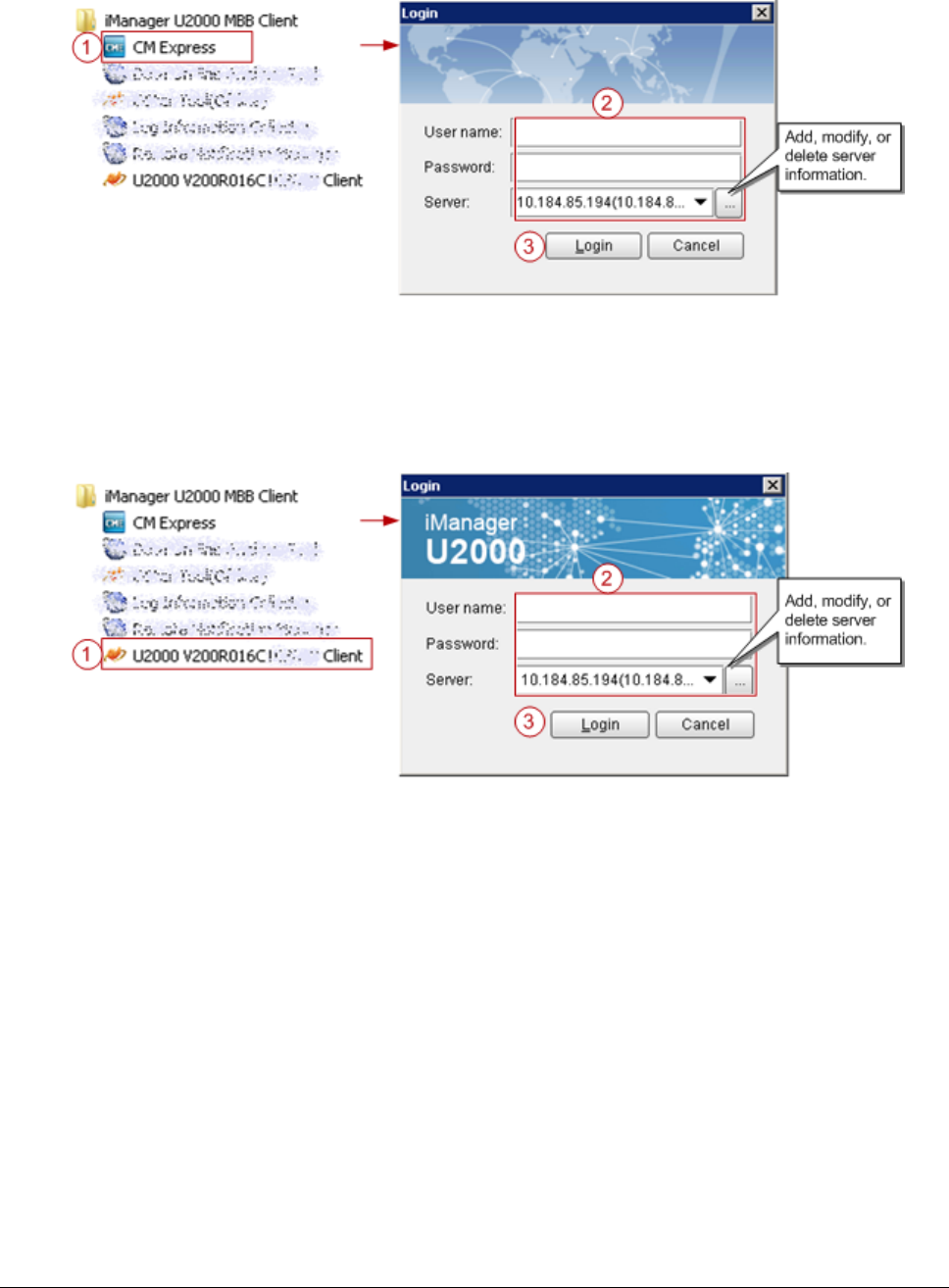
Issue 01 (2017-05-10)
Huawei Proprietary and Confidential
Copyright © Huawei Technologies Co., Ltd.
127
Start CME functions on the U2000 client in traditional mode.
On the Windows desktop, choose Start All Programs iManager U2000 MBB
Client.
After logging in to the U2000 client, choose CME on the menu bar of the
U2000 main window and then choose a submenu item to start the related CME
function.
2. Create a planned data area.
a. On the menu bar, choose Area Management Planned Area Create Planned Area
(CME client mode) or CME Planned Area Create Planned Area (U2000 client
mode). A dialog box is displayed for you to create a planned data area.
b. Set related information.
i. Enter the name of the planned data area.
ii. Select a user group.
c. Click OK. The CME starts to create the planned data area. After
successfully creating the planned data area, the CME automatically opens
it.
Issue 01 (2017-05-10)
Huawei Proprietary and Confidential
Copyright © Huawei Technologies Co., Ltd.
128
NOTE:
If a multimode base station capable of working in LTE mode is to be created, add the
controller associated to the base station to the planned area when you create a
planned area.
For details about how to create a planned data area, press F1 to obtain the online
help.
Parent topic: Preparing Common Base Station Deployment Data Files on the CME
4.2.1.2.1.1.4 Configuring Data on GUIs
This section describes how to initially configure a single base station on GUIs
using a default or user-defined template.
Creating Base Stations
This section describes how to create base stations. To create base stations, you
need to start the wizard provided by the CME for creating base stations, set
basic base station data, and select a required template. After the base stations
are created, configure global data and maintenance modes for the base stations
in the general configuration window of the CME.
Configuring eAN3810A Data
This section describes how to configure device data, transport data, and radio
data for the eAN3810A by using the CME.
Parent topic: Preparing Common Base Station Deployment Data Files on the CME
4.2.1.2.1.1.4.1 Creating Base Stations
This section describes how to create base stations. To create base stations, you
need to start the wizard provided by the CME for creating base stations, set
basic base station data, and select a required template. After the base stations
are created, configure global data and maintenance modes for the base stations
in the general configuration window of the CME.
Procedure
1. On the menu bar of the planned data area, choose CME OneAir Application
Create Base Station (U2000 client mode) or OneAir Application Create Base

Issue 01 (2017-05-10)
Huawei Proprietary and Confidential
Copyright © Huawei Technologies Co., Ltd.
129
Station (CME client mode). A dialog box is displayed for you to create base
stations.
2. Set site information.
a. Select eAN3810A from the Product type drop-down list.
b. Set basic base station information, including the base station name, ID,
version. The CME provides two types of base station templates:
Base Station template
Radio template
3. Click Next and set basic information and radio template for each RAT.
The eNodeB ID can be set to any valid value. After the configuration takes
effect, the base station name is automatically changed to ESN, and the
eNodeB ID is automatically changed to the value allocated on the U2000.
4. After the configuration is complete, click Next. The CME starts to create a
base station.
5. Click Finish to exit the wizard.
Parent topic: Configuring Data on GUIs
4.2.1.2.1.1.4.2 Configuring eAN3810A Data
This section describes how to configure device data, transport data, and radio
data for the eAN3810A by using the CME.
Procedure
1. Click the required tab (Controller/Base Station/Cell) in the left pane of
the planned data area. On the displayed tab page, select an item. The
navigation tree of involved configuration objects is displayed in the lower
part of the left pane. See Figure 1.
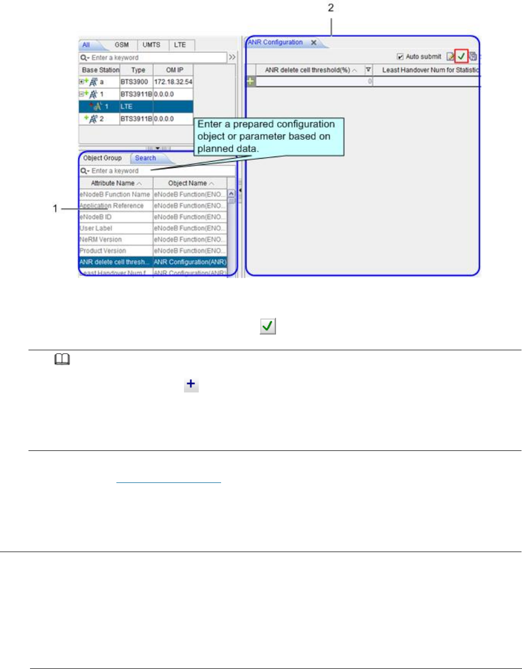
Issue 01 (2017-05-10)
Huawei Proprietary and Confidential
Copyright © Huawei Technologies Co., Ltd.
130
Figure 1 Configuration window
2. In area 1, select or search the MO to be configured based on the planned
data and double-click the MO. On the displayed page as shown in area 2, set
parameters as required, and click to save the parameter configuration.
NOTE:
To add a record, click in area 2 and set parameters as required.
After selecting a base station root node, you can search for the common configuration
objects in area 1. After selecting a RAT node, you can search for configuration objects
specific to the RAT in area 1. Therefore, you must select a node correctly. Otherwise,
target configuration objects may fail to be found in area 1.
Parent topic: Configuring Data on GUIs
4.2.1.2.1.1.5 Verifying Data
This section describes how to verify the validity and integrity of base station
configuration data before you export the data. Validity verification is to check
whether base station configuration data meets NE configuration rules. If the
data does not meet the rules, it is not sent to NEs. Integrity verification is
to check whether base station configuration data is complete. If the data is

Issue 01 (2017-05-10)
Huawei Proprietary and Confidential
Copyright © Huawei Technologies Co., Ltd.
131
incomplete, services cannot be provided. For example, a base station without
cell data cannot provide radio services.
Prerequisites
You have configured base station data.
Procedure
1. In the left pane of the planned data area, right-click a base station whose
data you want to verify and choose Check Datafrom the shortcut menu. The CME
starts to verify the data validity and integrity of the base station.
2. View the verification results and modify incorrect data until the validity
and integrity of the data are successfully verified.
Parent topic: Preparing Common Base Station Deployment Data Files on the CME
4.2.1.2.1.1.6 Exporting Configuration Files
Exporting the Deployment Lists and Configuration Files of Base Stations
This section describes how to export the deployment lists and configuration
files of base stations. After base stations are initially configured on the CME,
you need to export the deployment lists and configuration files of the base
stations, and then use the automatic deployment function on the U2000 client or
use a USB flash drive locally to load the data to the base stations for the data
to take effect.
Parent topic: Preparing Common Base Station Deployment Data Files on the CME
4.2.1.2.1.1.6.1 Exporting the Deployment Lists
and Configuration Files of Base Stations
This section describes how to export the deployment lists and configuration
files of base stations. After base stations are initially configured on the CME,
you need to export the deployment lists and configuration files of the base
stations, and then use the automatic deployment function on the U2000 client or
use a USB flash drive locally to load the data to the base stations for the data
to take effect.

Issue 01 (2017-05-10)
Huawei Proprietary and Confidential
Copyright © Huawei Technologies Co., Ltd.
132
Specifications and Restrictions
Deployment list: The naming convention is Auto_Deployment_List_ID of the
planned data area_time stamp.xml. If multiple NEs are selected at a time, the
NE data is exported to one deployment list.
Data configuration script: The script is in XML format. Each site has one
configuration script.
Procedure
1. On the menu bar, choose Advanced Export Auto Deployment Data (CME client
mode) or CME Advanced Export Auto Deployment Data (U2000 client mode). A
dialog box is displayed for you to export auto-deployment data.
2. Select Site creation expansion and click Next.
3. Select the base stations whose auto-deployment data you want to export, and
click Next.
4. Select a save path for the exported file and a method for processing data,
and click Next.
5. View data in the base station deployment list, and click Next. The CME
starts to verify data correctness and exports the data.
NOTE:
You are advised to set the connection type to Common.
The ESN is optional. If it is no set, you need to manually associate the ESN with the
related base station during the subsequent deployment commissioning.
You can only set the first-level subnet in the subnet information. To specify a subnet of
another level, you can adjust the subnet information in the U2000 topology after the base
station commissioning. If the user-specified subnet information does not exist on the
U2000, the U2000 automatically generates the subnet during the import of automatic
deployment data in the subsequent commissioning.
6. If the export is successful in U2000 client mode, set the following options:
Select Do not open the Auto Deployment windowto close the wizard.
Select Open the Auto Deployment window. The CME automatically switches to
the auto-deployment window and creates a commissioning task.
Select Open the Auto Deployment window and start Auto Deployment task. The
CME automatically switches to the auto-deployment window and starts a
commissioning task.
7. Click Finish.
Issue 01 (2017-05-10)
Huawei Proprietary and Confidential
Copyright © Huawei Technologies Co., Ltd.
133
NOTE:
The save paths for the exported data configuration scripts and deployment lists are as
follows:
Data configuration scripts: export directory\CfgData\base station name
Deployment lists: export directory\ADList\
You can use the script executor to check and edit the exported data configuration scripts.
Parent topic: Exporting Configuration Files
4.2.1.2.1.2 Preparing an SD Card
This section describes how to prepare an SD card before loading the software
package and data configuration file onto a eAN3810A.
Prerequisites
The data copy rights have been obtained for the computer used to make the SD
card.
Prerequisites
Item
Description
SD card
The SD card must be the one delivered with Huawei eAN3810A.
USB making and protection
tool
The tool is saved in U2000 installation
directory\client\client\USBProtector on the computer where
the U2000 is installed.
For details about the save path of each type of file in the SD card,
seeDirectory Structure on a MicroSD Card. the tool will automatically generate \ MBTS
path, do not manually add the path.
Procedure
1. Choose Start > Programs > iManager U2000 MBB Client > USB Making and
Protection Tool to start the tool.
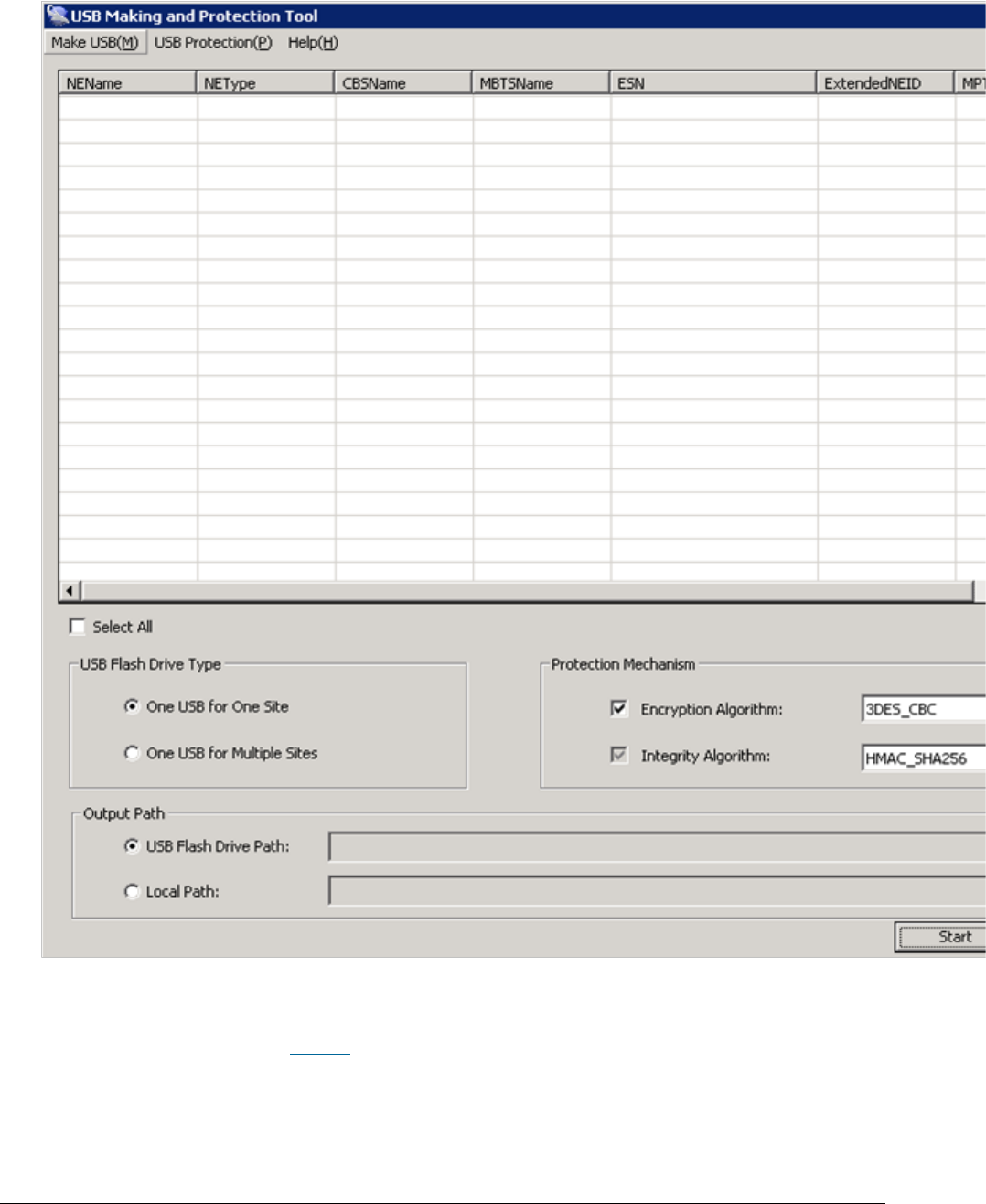
Issue 01 (2017-05-10)
Huawei Proprietary and Confidential
Copyright © Huawei Technologies Co., Ltd.
134
Figure 1 USB making and protection tool
2. Choose Make USB(M) > Enterprise Private Network Product (for AirNode Only).
The Enterprise Private Network Product (for AirNode Only) dialog box is
displayed, as shown in Figure 2.
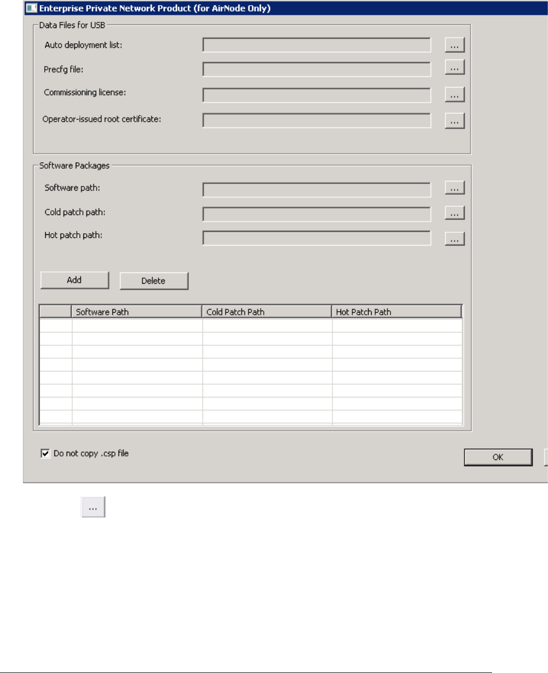
Issue 01 (2017-05-10)
Huawei Proprietary and Confidential
Copyright © Huawei Technologies Co., Ltd.
135
Figure 2 Enterprise Private Network Product (for AirNode Only)
a. Click to the right of Auto deployment list to specify the directory
where the
Auto_Deployment_List_[Date].xml
file exported from the CME is
stored, as shown in the following figure.
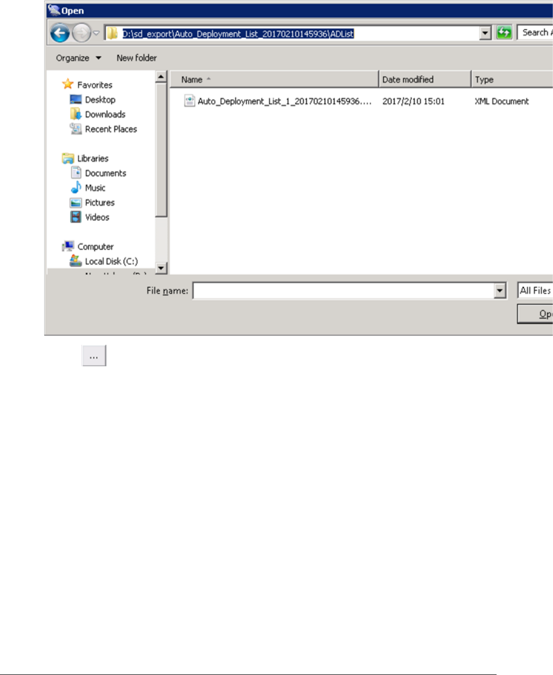
Issue 01 (2017-05-10)
Huawei Proprietary and Confidential
Copyright © Huawei Technologies Co., Ltd.
136
b. Click to the right of Precfg file to specify the directory where the
preconfiguration file
Precfg.ini
is stored, as shown in the following
figure.
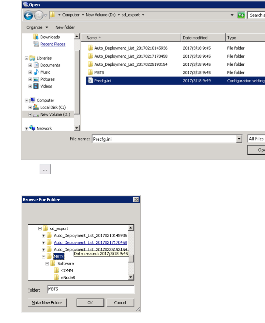
Issue 01 (2017-05-10)
Huawei Proprietary and Confidential
Copyright © Huawei Technologies Co., Ltd.
137
c. Click to the right of Software path to specify the directory where
the software package is stored, as shown in the following figure.
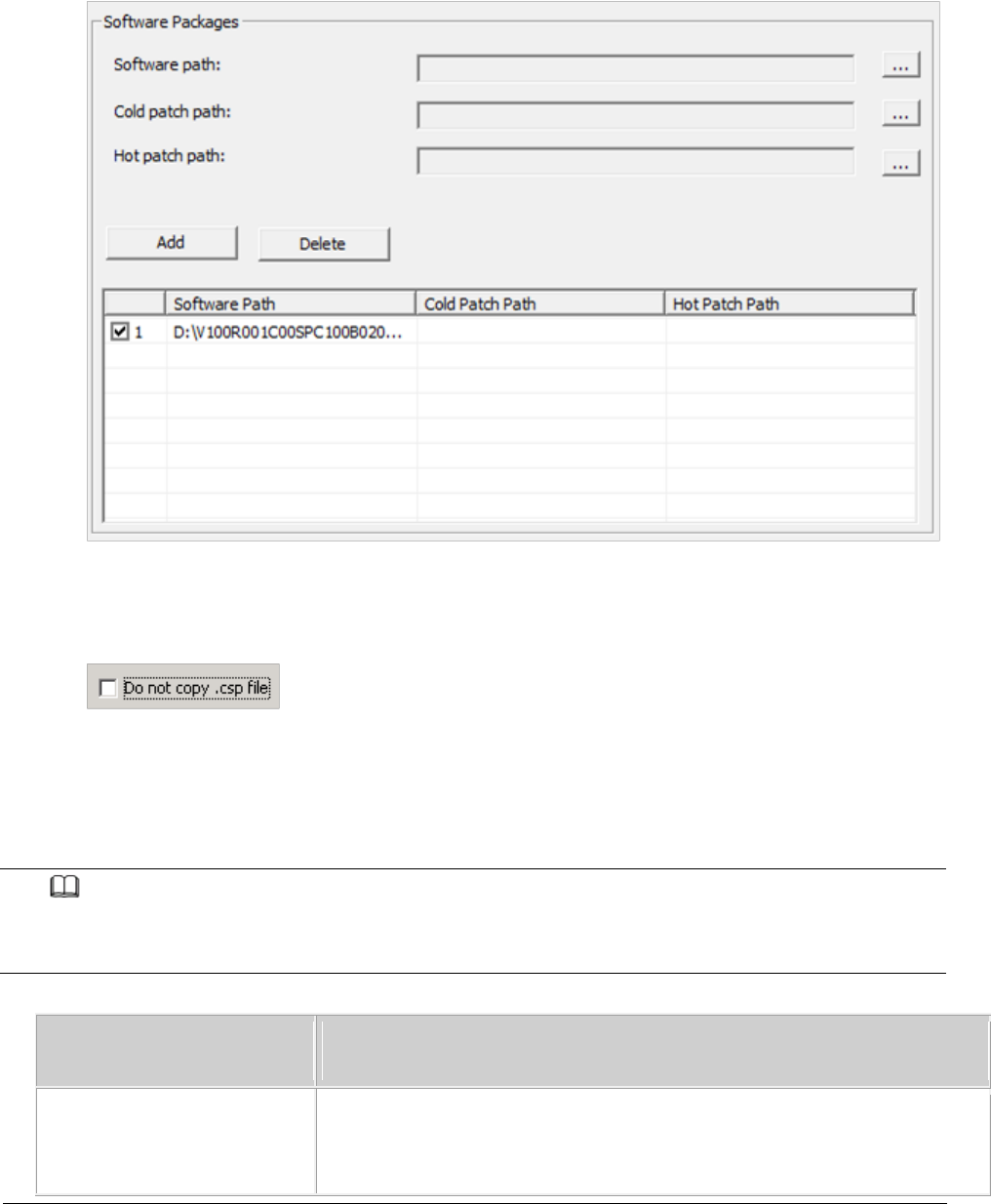
Issue 01 (2017-05-10)
Huawei Proprietary and Confidential
Copyright © Huawei Technologies Co., Ltd.
138
Click Add to add the software package directory, as shown in the
following figure.
d. Deselect the Do not copy .csp file option according to the site
deployment scenario, as shown in the following figure.
3. Set the local save paths for the software package and data files based on
the type of SD card directory. Then, click OK. And then according to the
number of open station number (One USB for One Site or One USB for Multiple
Sites) and the output directory, clickStart .
NOTE:
When making different types of directories on an SD card, specify items listed in the
Information to Set column only and do not set items that are not listed in this column.
Option
Information to Set
Directory for upgrading
the software and
Software path: mandatory, save path of the files
decompressed from a specified version software package
Cold patch path: optional, save path of the files

Issue 01 (2017-05-10)
Huawei Proprietary and Confidential
Copyright © Huawei Technologies Co., Ltd.
139
Option
Information to Set
updating configuration
files
decompressed from a specified cold patch package
Hot patch path: optional, save path of the files
decompressed from a specified hot patch package
Based on different version combinations of NEs to be deployed
in the deployment list, specify Software path, Cold patch
path, or Hot patch path. Then, click Add to add the path to
the software version list. Based on the target version
information in the deployment list, the USB making and
protection tool copies different versions to the
corresponding directories of the NEs to be deployed. If an
unnecessary software version is added, you can click Delete
to remove this software version.
NOTE:
The software version of the original and target versions must be eAN3810A
V100R001C00SPC200 and later.
Auto deployment list: mandatory. Select the deployment list
exported from the CME.
The exported deployment list is saved in export path/ADList/
by default. Engineers must select the only .xml file in this
directory.
Do not copy .csp file: It is good practice to deselect this
option. In this case, all files and integrity protection
information except the .csp files are saved in the
directories and you can send them through emails. Then, copy
the SD card directories to the SD card containing the intact
software package. Use this SD card to upgrade the software
and update configuration files.
Directory for updating
configuration files only
Auto deployment list: mandatory. Select the deployment list
exported from the CME. The exported deployment list is saved
in export path/ADList/ by default. Engineers must select the
only .xml file in this directory.
NE Type and Service Mode: mandatory. Select LTE based on the
working mode of the NE.
Do not copy .csp file: selected by default.
The USB making and protection tool automatically parses and displays the
information of the target NE on the USB Making and Protection Tool window.
Select the NE that requires an SD card. After all NE information is

Issue 01 (2017-05-10)
Huawei Proprietary and Confidential
Copyright © Huawei Technologies Co., Ltd.
140
correctly specified, select a deployment mode in the USB Flash Drive Type
area.
Option
Description
One USB for One Site
Save the information about each NE to an
independent SD card.
One USB for Multiple Sites
Save the information about all NEs to an
SD card.
This mode requires that each NE be
configured with a unique ESN.
In the Protection Mechanism area, select algorithms as required from the
Encryption Algorithm and Integrity Algorithm drop-down lists.
Encryption Algorithm is optional. It is selected by default and can be
cleared. Encryption Algorithm can be set to DES3_CBC, AES192_CBC, or
AES256_CBC. The default value DES3_CBC is recommended.
Integrity Algorithm is mandatory. It is selected forcibly and cannot be
cleared. Integrity Algorithm can be set to HMAC_SHA1 or HMAC_SHA256. The
default value HMAC_SHA1 is recommended.
In the Output Path area, specify a save path.
Option
Description
USB Flash Drive Path
Save all the information to an SD card. All
the directories of one SD card are prepared
at a time.
One USB for One Site: In this mode,
select only one NE and save this NE's
information to the SD card.
One USB for Multiple Sites: In this
mode, save the information about all NEs
to an SD card. The software package is
shared by all NEs and the data
configuration files are distinguished by
directories named after ESN.
Local Path
Save all the information to the specified
Issue 01 (2017-05-10)
Huawei Proprietary and Confidential
Copyright © Huawei Technologies Co., Ltd.
141
Option
Description
directory on a local computer.
One USB for One Site: In this mode, a
folder is created in a specified
directory for this NE and named after NE
name. In addition, NE information is
saved in this folder.
One USB for Multiple Sites: In this
mode, save the information about all NEs
to a specified directory. The software
package is shared by all NEs and the
data configuration files are
distinguished by directories named after
ESN.
NOTE:
The existing data configuration files may be damaged when being copied, encrypted, or
integrity protected. To prevent any damages, ensure that USB Flash Drive Path and Local Path
do not contain any files or directories.
Click Start.
During the procedure, the USB making and protection tool automatically
performs the following operations:
Applies integrity protection and encryption protection to files in the SD
card directories according to manual settings.
Copies the configuration files to the SD card directories of corresponding
NEs according to the save path of configuration files in the deployment
list.
Copies all files under the directory specified by Software path to the SD
card directories of corresponding NEs according to the directory structure
of the SD card.
Click OK in the dialog box displayed after the SD card is prepared.
Optional:If Output Path is set to Local Path, copy the files to the SD card.
If Local Path is set to Computer/DataCenter(D:)/SD in step 6:
One USB for One Site: Choose Computer > DataCenter(D:) > SD. If the NE to
be deployed is site 1, copy the MBTS folder from the Site1 folder to the
SD card. See Figure 3.
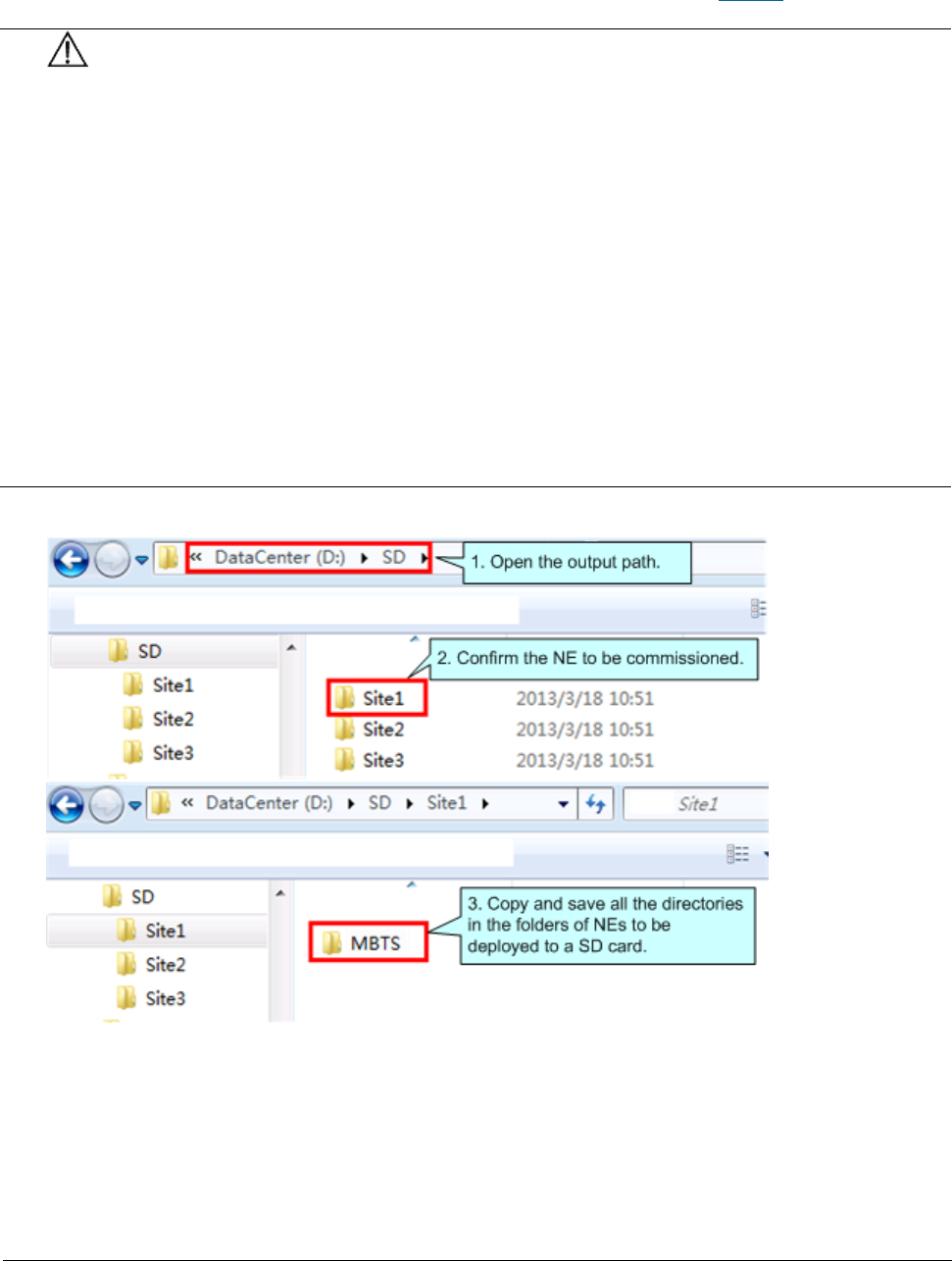
Issue 01 (2017-05-10)
Huawei Proprietary and Confidential
Copyright © Huawei Technologies Co., Ltd.
142
One USB for Multiple Sites: Choose Computer > DataCenter(D:) > SD. Copy
the MBTS folder from the SD folder to the SD card. See Figure 4.
NOTICE:
After a file is copied from a computer to an SD card, the file may change
due to faults on hardware or the Windows OS, but this seldom occurs. If
the problem occurs, you can copy the file from another computer, to
another SD card, or restart the OS and copy the file again.
To remove an SD card from the computer after the files are copied to the
SD card, eject or safely remove the SD card from the Windows OS. If the SD
card is forcibly ejected, the files in the SD card may be damaged. As a
result, software and data configuration files cannot be loaded by using
the SD card.
When transferring files for an SD card, do not copy the .xml files from a
remote desktop to a local computer. Otherwise, deployment will fail. You
are advised to compress the required files into a .rar or .zip file for
file transfer.
Figure 3 File copy procedure in One USB for One Site mode
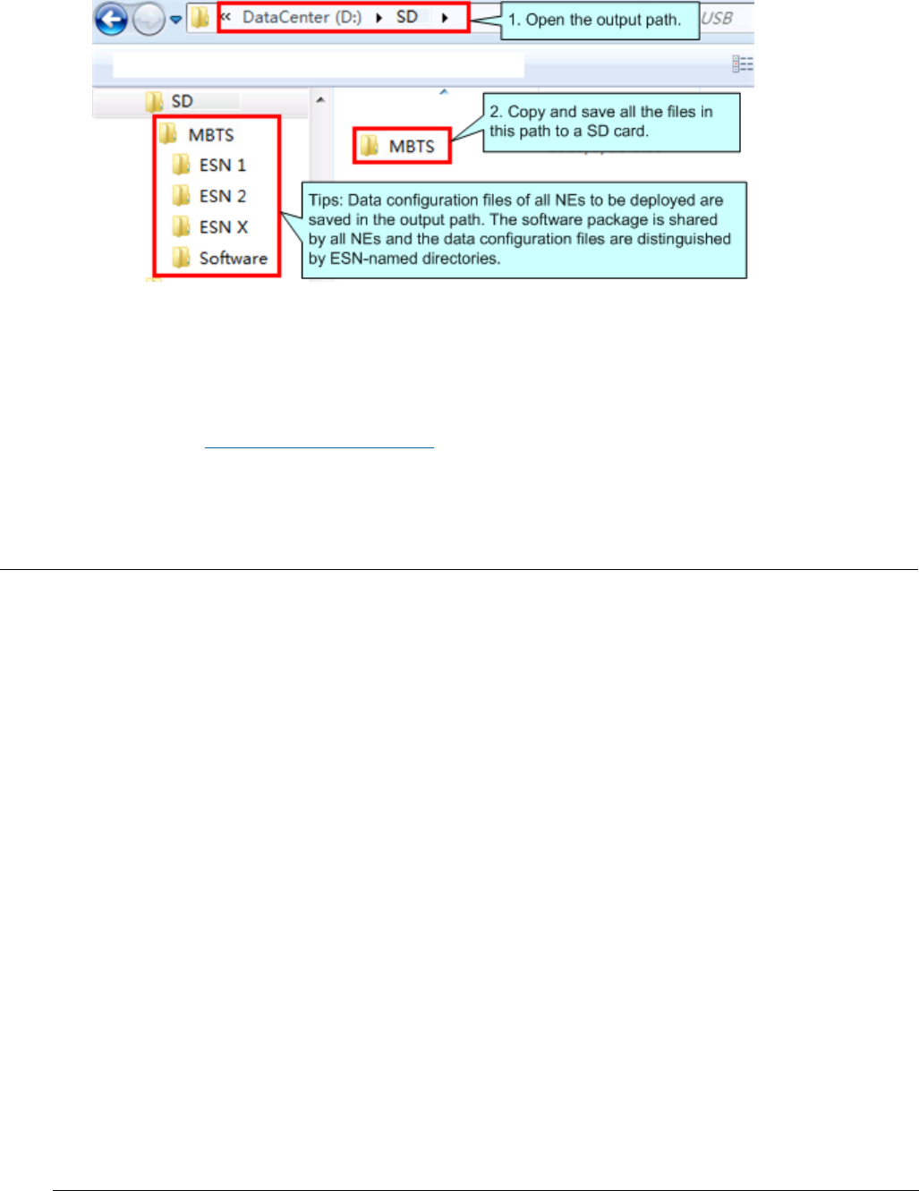
Issue 01 (2017-05-10)
Huawei Proprietary and Confidential
Copyright © Huawei Technologies Co., Ltd.
143
Figure 4 File copy procedure in One USB for Multiple Sites mode
Optional: If you need to preset the operator's root certificate in the SD
card, you can manually copy the root certificate file provided by the
carrier to the SD card: \ MBTS directory.
Parent topic: Preparation for Site Deployment
4.2.1.2.1.3 Checking a Transport Network
This section describes how to check a transport network. The transport network
affects the Automatic OMCH Establishment feature. Therefore, before
commissioning an eAN3810A,O&M engineers must check whether the OMCH networking
and the network equipment meet the configuration requirements of the
corresponding scenario.
Check Methods
O&M engineers can check whether the transport network meets the configuration
requirements of the Automatic OMCH Establishment feature by using either of the
following methods:
Method 1: Confirm with the department in charge of the transport network whether
the transport network meets the requirements.
Method 2:
Check the network connectivity. If nodes in the transport network can be
pinged, ping the port corresponding to each node to check whether the
transmission channel at each node is ready.
Check whether the network equipment at each node is configured as required to
ensure that an eAN3810A can automatically establish the OMCH.

Issue 01 (2017-05-10)
Huawei Proprietary and Confidential
Copyright © Huawei Technologies Co., Ltd.
144
Parent topic: Preparation for Site Deployment
4.2.1.2.1.4 Checking the SD Card Port Status
Prerequisites
The transmission network is ready.
The eAN3710A is connected to the U2000 or Web LMT.
Procedure
1. Log in to the U2000 or Web LMT. Run the LST MICROSDCARDPORT command to
verify that the Port Switch parameter is On.
2. To list the configuration of the Micro SD card port, run the following command:
3. LST MICROSDCARDPORT:;
4. The result is as follows:
5. +++ 0 2015-06-17 10:29:41
6. O&M #1
7. %%LST MICROSDCARDPORT:;%%
8. RETCODE = 0 Operation succeeded.
9.
10. List Micro SD Card Port Parameter
11. ---------------------------------
12. Port Switch = On
13. (Number of results = 1)
14.
15.
16. --- END
17.Log in to the U2000 or Web LMT. Run the SET MICROSDCARDPORT command with the
Port Switch parameter set to On.
NOTE:
The default value of Port Switch parameter is On upon factory delivery.
Parent topic: Preparation for Site Deployment
4.2.1.2.1.5 Preparing Dialing Test Tools

Issue 01 (2017-05-10)
Huawei Proprietary and Confidential
Copyright © Huawei Technologies Co., Ltd.
145
Dialing tests are performed by using test terminals to check whether deployed
eAN3810A can provide services properly. Prepare test terminals and ensure that
the test subscriber identity module (SIM) cards have registered with the Core
Network.
Parent topic: Preparation for Site Deployment
4.2.1.3 Hardware installation check phase
Hardware Installation and Power-on Check
This section describes how to perform hardware installation and power-on checks
at the site after eAN3810A hardware is installed. If a MicroSD card is used for
local deployment, engineers at the site need to insert the MicroSD card to the
eAN3810A to load software and the configuration file.
Parent topic: MicroSD Card Site Deployment
4.2.1.3.1 Hardware Installation and Power-on
Check
This section describes how to perform hardware installation and power-on checks
at the site after eAN3810A hardware is installed. If a MicroSD card is used for
local deployment, engineers at the site need to insert the MicroSD card to the
eAN3810A to load software and the configuration file.
Prerequisites
The SD card has been prepared.
The eAN3810A is working correctly.
Context
The port for housing a MicroSD card is enabled by default on the eAN3810A.
Insert a MicroSD card into the powered on eAN3810A and then restart the eAN3810A
to read data from the MicroSD card. Alternatively, insert the MicroSD card into
the powered off eAN3810A and then power on the eAN3810A.

Issue 01 (2017-05-10)
Huawei Proprietary and Confidential
Copyright © Huawei Technologies Co., Ltd.
146
Table 1 Precautions for using an SD card
Deployment Mode
Precautions
Site deployment
The eAN3810A automatically detects the MicroSD card and
installs the driver for the card after a MicroSD card is
inserted into the eAN3810A. Then, the eAN3810A
automatically reads the files in the fixed directories on
the MicroSD card and checks the file names and formats.
The eAN3810A compares the software version and
configuration data on the MicroSD card with those on the
eAN3810A. If consistent, it does not load the software or
configuration file on the MicroSD card. If inconsistent,
it loads the software and configuration file on the
MicroSD card.
Note the following points about loading:
If the MicroSD card only stores software, the eAN3810A
loads only the software.
If the MicroSD card only stores configuration files,
the eAN3810A loads only the target configuration file.
The eAN3810A does not load the software or
configuration file on the MicroSD card and its RUN
indicator indicates a loading failure (steady on) in
any of the following conditions:
The MicroSD card is not intended for it.
The expected directories or files are not present.
The directories or file formats are not correct.
Data in the MicroSD card is not encrypted or
integrity protected.
Procedure
U2000-based commissioning
1. Ensure that the eAN3810A hardware has been installed and has passed the
installation check. For details about how to perform the hardware
installation check, see section "Installation Check" in eAN3810A
Installation Guide.
2. Perform the power-on check. For details about how to perform the power-on
check, see section "Power-On Check" in eAN3810A Installation Guide.

Issue 01 (2017-05-10)
Huawei Proprietary and Confidential
Copyright © Huawei Technologies Co., Ltd.
147
SD card+U2000-based commissioning
1. Ensure that the eAN3810A hardware has been installed and has passed the
installation check. For details about how to perform the hardware
installation check, see section "Installation Check" in eAN3810A
Installation Guide.
2. Determine whether to restart the eAN3810A after a MicroSD card is inserted
based on the power-on status of the eAN3810A.
If...
Then...
The eAN3810A has been powered on.
Insert the MicroSD card into the related
port on the eAN3810A. Remove and reinsert
the Ethernet cable for power supply, and
then go to 3.
The eAN3810A has not been powered on.
Insert the MicroSD card into the related
port on the eAN3810A. Connect the eAN3810A
to a PSE over an Ethernet cable. Power on
the eAN3810A, and then go to 3.
3. Perform the power-on check. For details about how to perform the power-on
check, see section "Power-On Check" in
eAN3810A Hardware Installation
Guide
.
Check the RUN indicator for hardware faults on the MicroSD card. The RUN
indicator blinks orange (on for 0.125s and off for 0.125s), if the
eAN3810A fails to read files on the MicroSD card or fails to be deployed.
The MicroSD card may be faulty and cannot be detected, if the RUN
indicator status does not change.
4. In configuration-free deployment scenarios, wait until the eAN3810A
automatically downloads the preconfiguration file and reads the
preconfigured information. In site deployment scenarios, wait until the
eAN3810A completes the following procedure: automatically loads and
activates the software and data configuration files, and restarts itself
to make them take effect.
Table 2 Mapping between the RUN indicator status and loading status
Issue 01 (2017-05-10)
Huawei Proprietary and Confidential
Copyright © Huawei Technologies Co., Ltd.
148
Loading Status
RUN Indicator Status
The loading succeeds
Slowly blinking (on for 1s and off for 1s)
for more than 1 minute
Loading...
Blinking orange and white alternately (on
for 0.125s and off for 0.125s)
The loading fails.
Blinking orange (on for 0.125s and off for
0.125s)
5. NOTE:
In MicroSD card deployment scenarios, the eAN3810A automatically activates the
downloaded software and configuration file and then restarts for them to take effect.
The activation and restart take about 30 minutes, during which the indicator status is
negligible.
During loading, do not remove the MicroSD card.
6. Remove the MicroSD card only after you have confirmed that the loading
succeeds.
Follow-up Procedure
If the software version is incorrect after the loading process is completed,
perform the following operations:
1. Insert a MicroSD card storing the correct software version to the eAN3810A.
2. Remove the MicroSD card after the eAN3810A loads the software package and
successfully completes the upgrade.
Parent topic: Hardware installation check phase
4.2.1.4 Engineering Verification
This section describes how to complete the eAN3810A commissioning task, view
deployment results, and verify services.
Verification for Site Deployment
This section describes how to use the U2000 to complete eAN3810A commissioning
tasks and verify services.

Issue 01 (2017-05-10)
Huawei Proprietary and Confidential
Copyright © Huawei Technologies Co., Ltd.
149
Parent topic: MicroSD Card Site Deployment
4.2.1.4.1 Verification for Site Deployment
This section describes how to use the U2000 to complete eAN3810A commissioning
tasks and verify services.
Viewing Deployment Results at Sites
This section describes how to view deployment results at sites based on
indicator status.
Viewing Deployment Results on the U2000
This section describes how to view deployment results after an eAN3810A is
powered on.
Handling Alarms
This section describes how to handle alarms generated by a newly deployed
eAN3810A. All active alarms must be cleared during the commissioning.
Disabling the SD Card Port
Verifying Services
This section describes how to verify that UEs can attach to the eAN3810A and
perform ping services.
Parent topic: Engineering Verification
4.2.1.4.1.1 Viewing Deployment Results at Sites
This section describes how to view deployment results at sites based on
indicator status.
Procedure
Check the status of indicators on a newly deployed eAN3810A.
The following table shows the indicator status if an eAN3810A is deployed
successfully and working properly. See Table 1

Issue 01 (2017-05-10)
Huawei Proprietary and Confidential
Copyright © Huawei Technologies Co., Ltd.
150
Table 1 Indicator status of a functional eAN3810A
Indicator
Status
RUN
Steady white
ETH
Slow blinking white (on for 1s and off for
1s)
LINK
Steady white
If the indicator status of an eAN3810A differs from that in the preceding table,
contact Huawei technical support engineers.
Parent topic: Verification for Site Deployment
4.2.1.4.1.2 Viewing Deployment Results on the
U2000
This section describes how to view deployment results after an eAN3810A is
powered on.
Context
After site deployment is completed, you need to log in to the Web LMT or connect
the eAN3710A to the U2000 within 30 minutes. Otherwise, the eAN3710A will be
rolled back to the source version upon timer expiry.
Procedure
1. Wait 3 to 4 minutes after an eAN3810A is powered on. Then, on the U2000,
choose Topology > Main Topology (traditional style), or double-click Topo
View in Application Center and then choose Topology > Main Topology
(application style). On the displayed Main Topology window, check whether
the eAN3810A topology is created. See the following Figure 1.
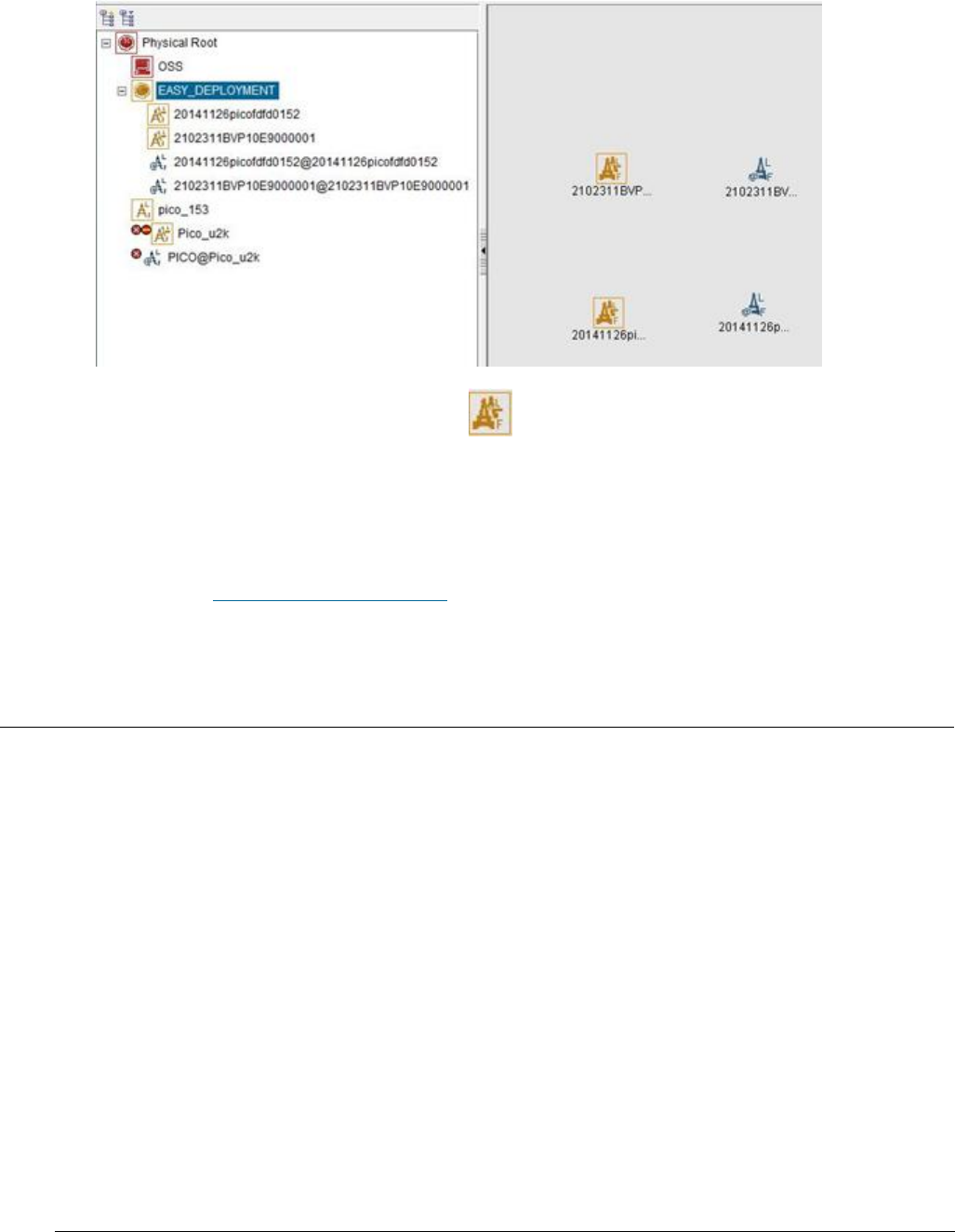
Issue 01 (2017-05-10)
Huawei Proprietary and Confidential
Copyright © Huawei Technologies Co., Ltd.
151
Figure 1 Main topology view
If the eAN3810A is displayed as in the main topology, the deployment
task is successful. No further action is required.
If no icon or another icon is displayed for the eAN3810A, the deployment
task fails. Proceed to the next step.
Parent topic: Verification for Site Deployment
4.2.1.4.1.3 Handling Alarms
This section describes how to handle alarms generated by a newly deployed
eAN3810A. All active alarms must be cleared during the commissioning.
Procedure
1. On the U2000, choose Monitor > Browse Current Alarms (traditional style), or
double-click Fault Management in Application Center and then choose Browse
Alarms > Browse Current Alarms (application style). On the displayed Browse
Current Alarm window, click Filter. The Filter dialog box is displayed.
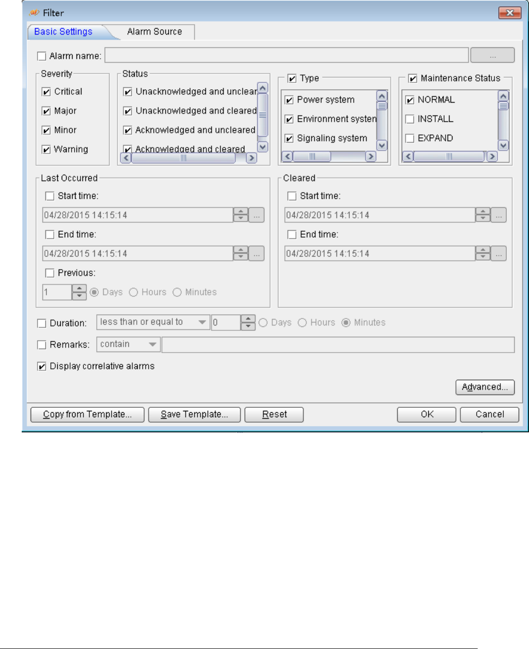
Issue 01 (2017-05-10)
Huawei Proprietary and Confidential
Copyright © Huawei Technologies Co., Ltd.
152
Figure 1 Filter dialog box
2. Click the Alarm Source tab and click the Custom option button. Then, click
Add and choose NE from the shortcut menu. The NE dialog box is displayed.
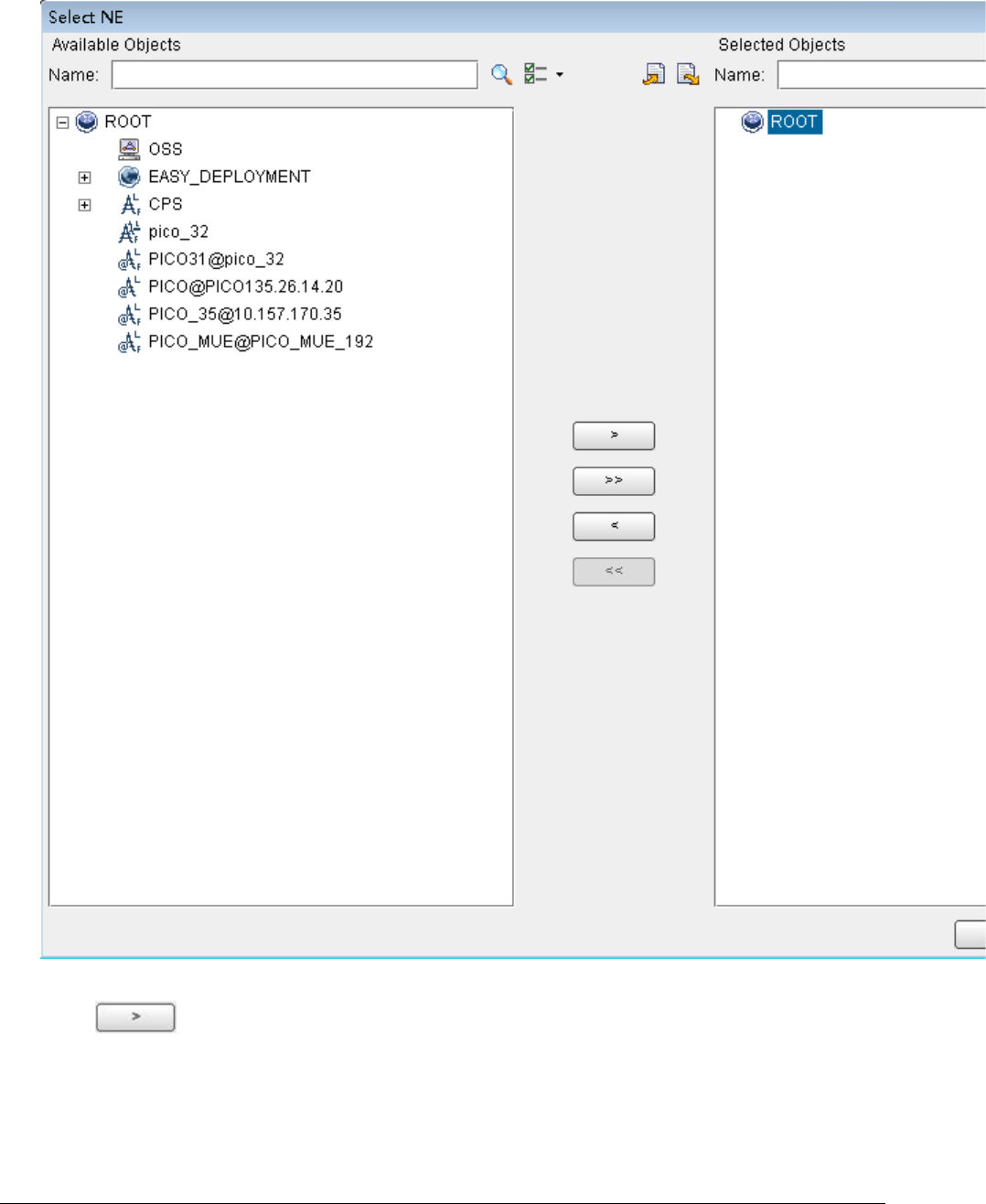
Issue 01 (2017-05-10)
Huawei Proprietary and Confidential
Copyright © Huawei Technologies Co., Ltd.
153
Figure 2 NE dialog box
3. In the Available Objects area on the left, select NEs in the navigation tree.
Click to add the selected NEs to the Selected Objects area on the
right. Then, click OK.
4. In the Filter dialog box, click OK. All alarms reported by the selected NEs
are displayed on the Browse Current Alarm window.

Issue 01 (2017-05-10)
Huawei Proprietary and Confidential
Copyright © Huawei Technologies Co., Ltd.
154
5. Check the alarms one by one to determine whether they are related to the new
eAN3810A deployment. If related, handle the alarms. For details about how to
handle the alarms, see the alarm reference.
Parent topic: Verification for Site Deployment
4.2.1.4.1.4 Disabling the SD Card Port
Prerequisites
The transmission network is ready.
The eAN3710A is connected to the U2000 or Web LMT.
Procedure
1. Log in to the U2000 or Web LMT. Run the SET MICROSDCARDPORT command with the
Port Switch parameter set to Off.
Parent topic: Verification for Site Deployment
4.2.1.4.1.5 Verifying Services
This section describes how to verify that UEs can attach to the eAN3810A and
perform ping services.
Prerequisites
Cells are activated.
UEs have been defined on the core network.
Procedure
1. Check whether UEs can successfully attach to the eAN3810A and perform ping
services.
Parent topic: Verification for Site Deployment

Issue 01 (2017-05-10)
Huawei Proprietary and Confidential
Copyright © Huawei Technologies Co., Ltd.
155
4.2.1.5 FAQ
This section describes the graphical user interfaces (GUIs) involved in
deployment and troubleshooting methods for common problems.
How Do I Set the U2000 Client Display Style?
The U2000 client has two display styles: application style and traditional style.
You can set the display style as required.
How Do I Prepare a Precfg.ini File?
This section describes how to prepare a Precfg.ini file. This file specifies the
software to be loaded during local deployment by a MicroSD card.
Directory Structure on a MicroSD Card
his section provides the save paths and names for files in a MicroSD card and
describes file usage.
Integrity and Encryption Protection on Files in MicroSD Cards
This section describes how to use the USB making and protection tool to apply
integrity and encryption protection to files in MicroSD cards. This prevents
malicious modification, unauthorized possession, and information disclosure.
Saving Alarms/Events
This section describes how to save alarms and events to acquire system operating
status in real time.
Parent topic: MicroSD Card Site Deployment
4.2.1.5.1 How Do I Set the U2000 Client Display
Style?
The U2000 client has two display styles: application style and traditional style.
You can set the display style as required.
Context
Switching between styles changes the overall usability of the U2000 client and
the way the U2000 client is launched. The U2000 client supports two display
styles:
Application style

Issue 01 (2017-05-10)
Huawei Proprietary and Confidential
Copyright © Huawei Technologies Co., Ltd.
156
Traditional style
Table 1describes the differences between the two styles.
Table 1 Differences between the traditional style and application style
Traditional Style
Application Style
The client is launched with all the
supported functions and applications.
The client is launched only with the
applications required by a user.
Menu items cannot be searched for.
You can search for menu items.
The Favorites feature is not supported.
You can add functions and menu items that
are frequently used to the Favorites tab.
Traditional welcome page features are
supported.
The welcome page features are not
supported.
Procedure
1. On the U2000, choose System Preferences(traditional style) or File
Preferences(application style) from the main menu.
2. In the Preferences dialog box, click Client Display Style Client Display
Style.
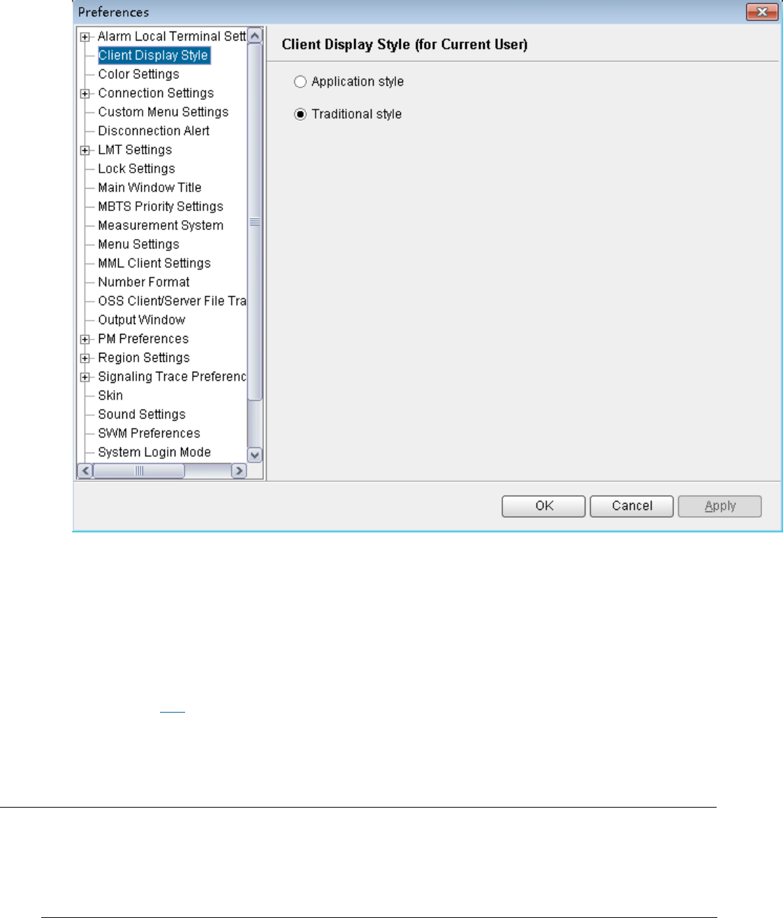
Issue 01 (2017-05-10)
Huawei Proprietary and Confidential
Copyright © Huawei Technologies Co., Ltd.
157
3. Select the Application style or Traditional style option button.
4. Click OK.
Follow-up Procedure
Restart the U2000 client for the settings to take effect.
Parent topic: FAQ
4.2.1.5.2 How Do I Prepare a Precfg.ini File?
This section describes how to prepare a Precfg.ini file. This file specifies the
software to be loaded during local deployment by a MicroSD card.
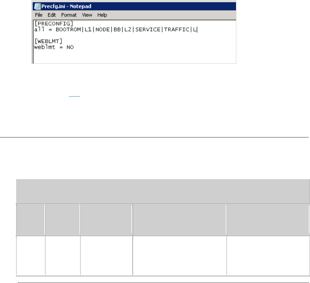
Issue 01 (2017-05-10)
Huawei Proprietary and Confidential
Copyright © Huawei Technologies Co., Ltd.
158
Context
The Precfg.ini file is contained in the software package and can be used only
after the target RAT is added.
Procedure
1. Open the Precfg.ini file using the Notepad in the Windows OS.
2. Add the target RAT at the end of the ALL record in the Precfg.ini file.
Add |L if the target RAT is LTE.
Retain the other settings in the file.
3. Save the file and retain the name Precfg.ini.
Parent topic: FAQ
4.2.1.5.3 Directory Structure on a MicroSD Card
his section provides the save paths and names for files in a MicroSD card and
describes file usage.
Table 1 Directory structure on a MicroSD card
Deploy
ment
Mode
File
Usage
How to Obtain
Save Path in the MicroSD
Card
Local
deploym
ent by
a
Configura
tion file
It
specifies
the
deployment
The MicroSD card making and
protection tool generates
the file based on the data
in the deployment list.
MBTS\DeployCfg.xml

Issue 01 (2017-05-10)
Huawei Proprietary and Confidential
Copyright © Huawei Technologies Co., Ltd.
159
Table 1 Directory structure on a MicroSD card
Deploy
ment
Mode
File
Usage
How to Obtain
Save Path in the MicroSD
Card
MicroSD
card
mode and
target
version.
It provides
save paths
and check
codes for:
Software
packages
Configura
tion
files
Certifica
tes
Commissio
ning
licenses
Version
software
package
Software
upgrade
Obtain the software package
from
http://support.huawei.com/e
nterprise/.
MBTS\Software\
MBTS\Software\
softwar
e version
NOTE:
When a MicroSD card stores
software of different versions,
the save paths are named by
software version.
Cold
patch
package
It is used to
apply a cold
patch.
Obtain the software package
from
http://support.huawei.com/e
nterprise/
MBTS\ColdPatch\
MBTS\ColdPatch\
cold
patch version
NOTE:
When a MicroSD card stores
cold patches of different
versions, the save paths are
named by cold patch version.

Issue 01 (2017-05-10)
Huawei Proprietary and Confidential
Copyright © Huawei Technologies Co., Ltd.
160
Table 1 Directory structure on a MicroSD card
Deploy
ment
Mode
File
Usage
How to Obtain
Save Path in the MicroSD
Card
Hot patch
package
It is used to
apply a hot
patch.
Obtain the software package
from
http://support.huawei.com/e
nterprise/
MBTS\HotPatch\
MBTS\HotPatch\
hot
patch version
NOTE:
When a MicroSD card stores
hot patches of different
versions, the save paths are
named by hot patch version.
Precfg.in
i
It specifies
the software
to be loaded.
It is manually prepared.
MBTS\Precfg.ini
NOTE:
For details about how to prepare
the Precfg.ini file.
Configura
tion file
Configuration
data update
It is generated by the CME
and exported with the
deployment list.
The USB making and
protection tool copies
the file to a MicroSD
card directory based on
the parameter settings
in the tool.
One SD card for a
single site:
MBTS\CFGDATA.XML
One SD card for
multiple sites: SD
card:\MBTS\ESN\SlotNo
.\CFGDATA.XML
Parent topic: FAQ
4.2.1.5.4 Integrity and Encryption Protection on
Files in MicroSD Cards

Issue 01 (2017-05-10)
Huawei Proprietary and Confidential
Copyright © Huawei Technologies Co., Ltd.
161
This section describes how to use the USB making and protection tool to apply
integrity and encryption protection to files in MicroSD cards. This prevents
malicious modification, unauthorized possession, and information disclosure.
Applying Integrity and Encryption Protection to Files in a Single MicroSD Card
This section describes how to apply integrity and encryption protection to files
in a single MicroSD card.
Applying Integrity and Encryption Protection to Files in Multiple SD Cards
This section describes how to apply integrity and encryption protection to files
in multiple SD cards.
Parent topic: FAQ
4.2.1.5.4.1 Applying Integrity and Encryption
Protection to Files in a Single MicroSD Card
This section describes how to apply integrity and encryption protection to files
in a single MicroSD card.
Prerequisites
The USB making and protection tool is ready. The tool is saved in
U2000
installation directory
\client\client\USBProtector on the computer where the
U2000 client is installed.
You have scanned the MicroSD card for viruses by using antivirus tools before
applying protection. This can prevent files on the computer from infections.
Files to be protected are ready.
Context
Integrity protection
The digital signatures in the software and patch packages are used to
verify integrity. Do not use the USB making and protection tool to apply
integrity protection to these files. Otherwise, deployments or upgrades
using a MicroSD card will fail.
Integrity protection must be applied to all other files.
Encryption protection
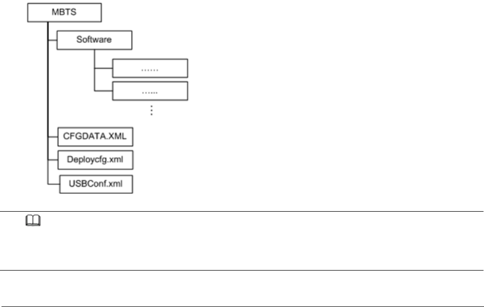
Issue 01 (2017-05-10)
Huawei Proprietary and Confidential
Copyright © Huawei Technologies Co., Ltd.
162
Do not apply encryption protection to any files in the SD card if the
target version of a base station upgrade does not support SD card-based
encryption. Otherwise, deployments or upgrades using an SD card will fail.
If the target version of a base station upgrade supports SD card-based
encryption,
Do not apply encryption to the version, BootROM, and patch software
packages. Otherwise, deployments or upgrades using an SD card will fail.
You must apply encryption to the CFGDATA.XML file for eAN3810A.
After you use the USB making and protection tool to apply integrity and
encryption protection to files, the USBConf.xml file is generated and the
file name cannot be changed. When loading files in the MicroSD card, the Pico
checks file integrity and decrypts the files based on the data in
the USBConf.xml file.
Procedure
1. Prepare the directory for files to be protected.
The directory structure is fixed. It cannot be modified, or deployments or
upgrades using a MicroSD card will fail. The following figure shows an
example with the CA server deployed in the secure domain.
Figure 1 Directory structure for files to be protected (single MicroSD card)
NOTE:
The USB making and protection tool applies integrity and encryption protection to files but
it cannot decrypt files. Back up the files to be protected before applying integrity and
encryption protection.
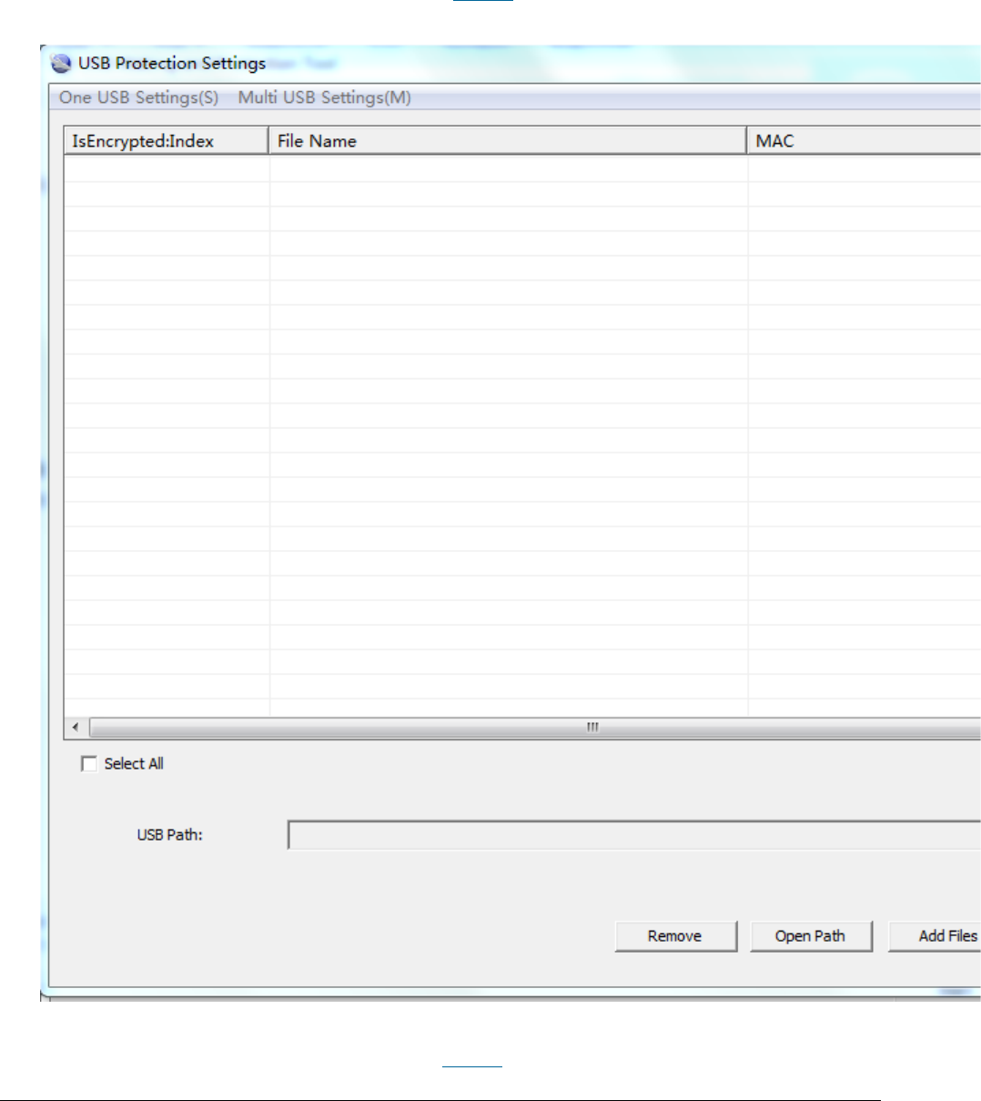
Issue 01 (2017-05-10)
Huawei Proprietary and Confidential
Copyright © Huawei Technologies Co., Ltd.
163
2. Choose Start > Programs > iManager U2000 MBB Client > USB Making and
Protection Tool to start the tool.
3. Choose USB Protection > USB Protection Settings. The USB Protection
Settings dialog box is displayed. See Figure 2
Figure 2 USB Protection Settings
4. Choose One USB Settings > Set Security Policies. The Set Security
Policies dialog box is displayed.See Figure 3
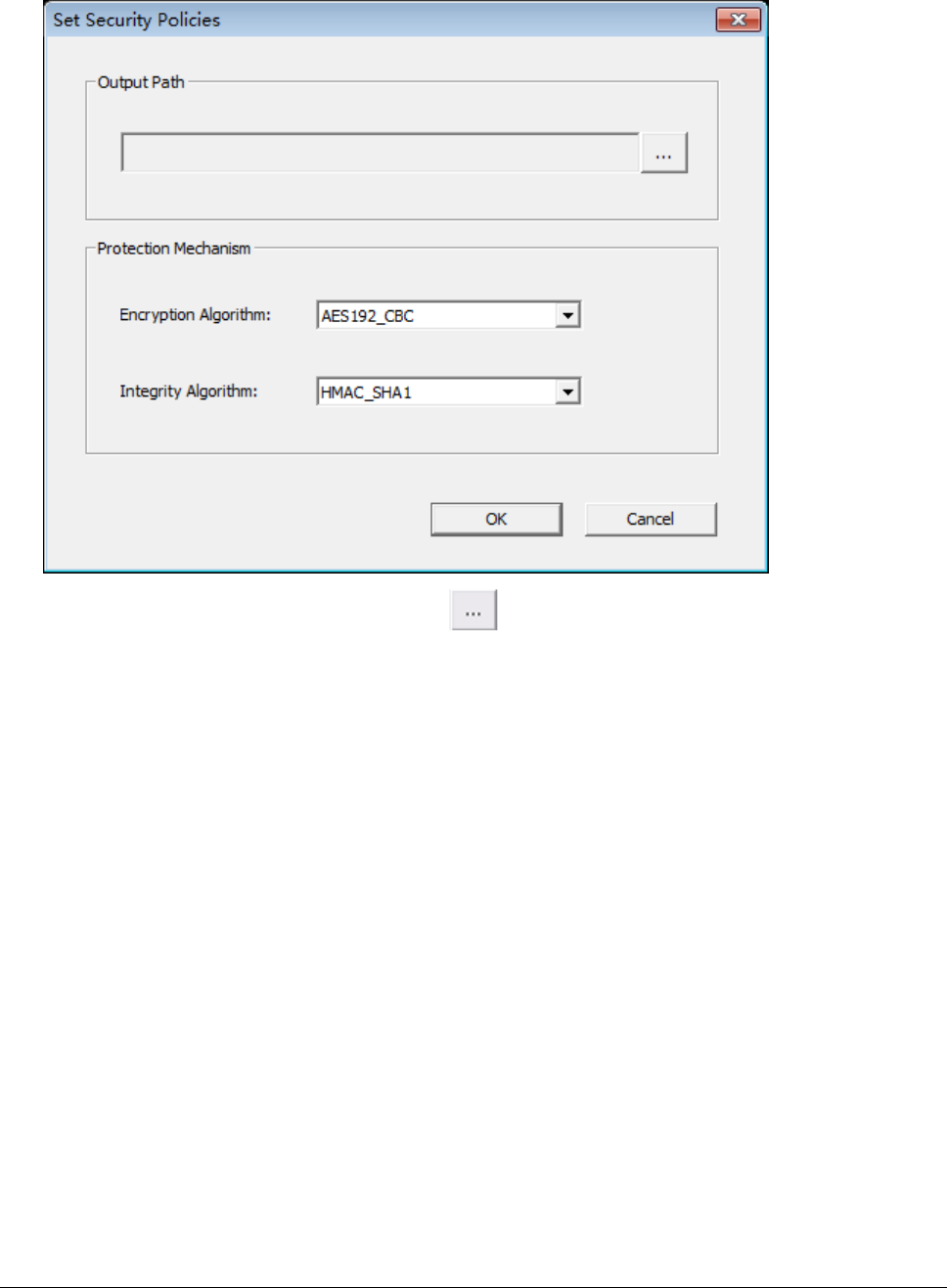
Issue 01 (2017-05-10)
Huawei Proprietary and Confidential
Copyright © Huawei Technologies Co., Ltd.
164
Figure 3 Set Security Policies
a. In the Output Path area, click to specify a save path for
the USBConf.xml file and then click OK.
b. In the Protection Mechanism area, select algorithms as required from
the Encryption Algorithm and Integrity Algorithm drop-down lists.
Encryption Algorithm can be set to:
DES3_CBC
AES192_CBC
AES256_CBC
Integrity Algorithm can be set to:
HMAC_SHA1
HMAC_SHA256
You can choose any encryption and integrity algorithms but the defaults
are recommended.
c. Click OK.
5. Choose One USB Settings Set USB Pathto specify the root path on the local
computer for the folder storing files to be protected and click OK . The
path information will be displayed in the USB Path area after the setting

Issue 01 (2017-05-10)
Huawei Proprietary and Confidential
Copyright © Huawei Technologies Co., Ltd.
165
succeeds.In the example shown in the following figure, the path must be set
to D:\USBencrypt\NodeB, D:\USBencrypt\eNodeB, or D:\USBencrypt\MBTS.
Figure 4 Directory structure example
6. Add files to be protected, and select the IsEncrypted:Index check box. The
system applies only integrity protection to added files by default. If
encryption must be applied to, select the IsEncrypted:Index check box.
Option
Description
Adding a single file
Click Add Files to select the file to be
protected specified in 5.
Adding multiple files
Click Open Path and select the path
specified in 5. The tool automatically adds
all the files in the indicated directory.
NOTE:
The tool automatically adds the .csp file in the folder but will
not apply integrity protection to it.
7. NOTICE:
8. describes the files for which integrity and encryption protection must be
applied. You must follow these rules; otherwise, deployments or upgrades
using a MicroSD card will fail.

Issue 01 (2017-05-10)
Huawei Proprietary and Confidential
Copyright © Huawei Technologies Co., Ltd.
166
Integrity protection and encryption must not be applied to software and
patch packages.
Integrity protection must be applied to the Precfg.ini file. However,
encryption must not be applied to the file.
Integrity protection must be applied to other files. Encryption can be
applied to them based on customers' security requirements.
Click Execute Protect
The system applies the selected encryption protection to files, and
applies integrity protection to all files in the file list area based on
the specified integrity algorithm.
Sizes of files remain the same after encryption is completed because the
system uses a symmetrical encryption algorithm.
Click OK, when a dialog box is displayed indicating the completion of
integrity and encryption protection.
Integrity protection codes of files are displayed in the MAC address list.
The USBConf.xml file generated by the tool is saved in the path specified
in 4.1.
NOTE:
Ensure that the path for configuration files in the USBConf.xml file is consistent with the
save path in the MicroSD card.
Delete existing files on the MicroSD card. Copy the folder containing the
files that have been protected by using the tool from the computer to the
MicroSD card. All the files in the folder must be copied. SeeFigure 5
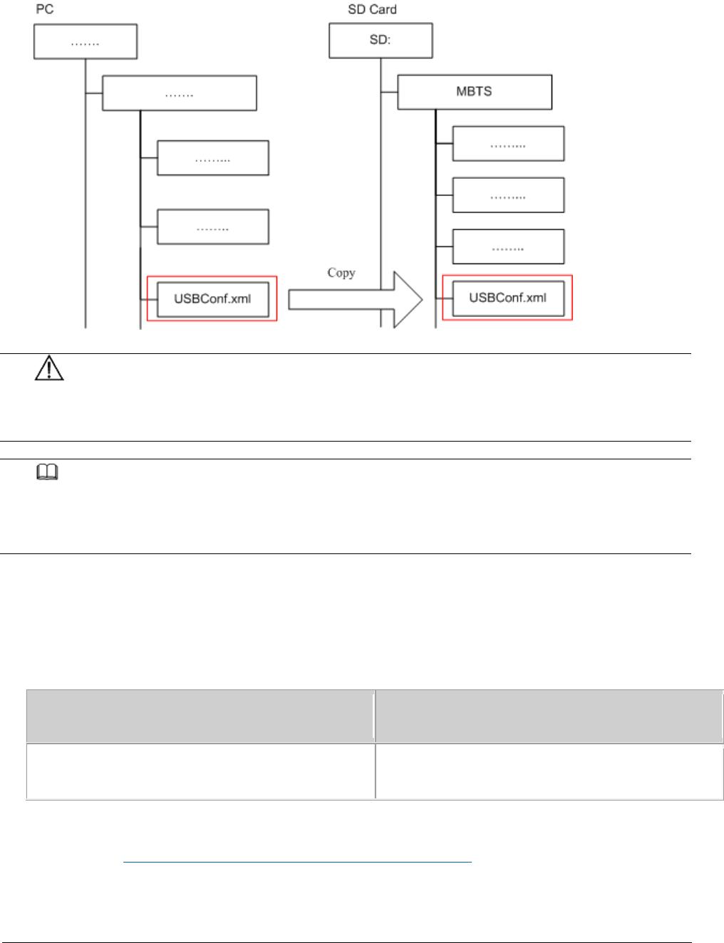
Issue 01 (2017-05-10)
Huawei Proprietary and Confidential
Copyright © Huawei Technologies Co., Ltd.
167
Figure 5 Copying the USBConf.xml file
NOTICE:
Do not change the directory structure in the folder when files are being
copied. Otherwise, deployments or upgrades using a MicroSD card will fail.
NOTE:
f software needs to be upgraded but no software package is contained in the MicroSD card,
manually copy the software package to the fixed directory. For details about the save path
for the software package in the MicroSD card.
(Optional) If the USBConf.xml file has not been saved in the NodeB eNodeB ,
or MBTS folder when you perform step 4.1 you must copy the USBConf.xml
file to the fixed path in the MicroSD card, in accordance with the following
table. Otherwise, the files in the MicroSD card cannot be downloaded.
Option
Description
eAN3810A
MicroSD card:\MBTS\USBConf.xml
Parent topic: Integrity and Encryption Protection on Files in MicroSD Cards

Issue 01 (2017-05-10)
Huawei Proprietary and Confidential
Copyright © Huawei Technologies Co., Ltd.
168
4.2.1.5.4.2 Applying Integrity and Encryption
Protection to Files in Multiple SD Cards
This section describes how to apply integrity and encryption protection to files
in multiple SD cards.
Prerequisites
You have obtained the USB making and protection tool (tool for preparing and
protecting an SD card) on the PC where the U2000 is installed. The save path
of this tool on the PC is U2000 installation
directory\client\client\USBProtector.
You have scanned viruses for the SD cards by using the anti-virus tool before
applying protection to files. This can prevent files on the PC from
infections.
Files in the SD cards are ready for integrity and encryption protection.
Context
Integrity protection
The digital signatures in the version, and patch software packages are
verified for integrity verification. Do not use the USB making and
protection tool to apply integrity protection to them. Otherwise,
deployments or upgrades using an SD card will fail.
You must apply integrity protection to all files except for the version and
patch software packages.
Encryption protection
Do not apply encryption to the version and patch software packages and the
Precfg.ini file. Otherwise, deployments or upgrades using an SD card will
fail.
You must apply encryption to the VERCFG.XML file.
After you use the USB making and protection tool to apply integrity and
encryption protection to files in the SD card, the USBConf.xml file is
generated and the file name cannot be changed. When loading files in the SD
card, the base station performs integrity check and decryption by using data
in the USBConf.xml file.
Procedure

Issue 01 (2017-05-10)
Huawei Proprietary and Confidential
Copyright © Huawei Technologies Co., Ltd.
169
1. Prepare the directory for files to be protected.
NOTE:
The USB making and protection tool directly applies integrity and encryption protection to
files but it cannot decrypt files. Back up the files before applying integrity and
encryption protection to those files.
2. Choose StartProgramsiManager U2000 MBB ClientUSB Making and Protection Tool
to start the tool.
3. Choose USB ProtectionUSB Protection Settings. The USB Protection Settings
dialog box is displayed. See the followingFigure 1.
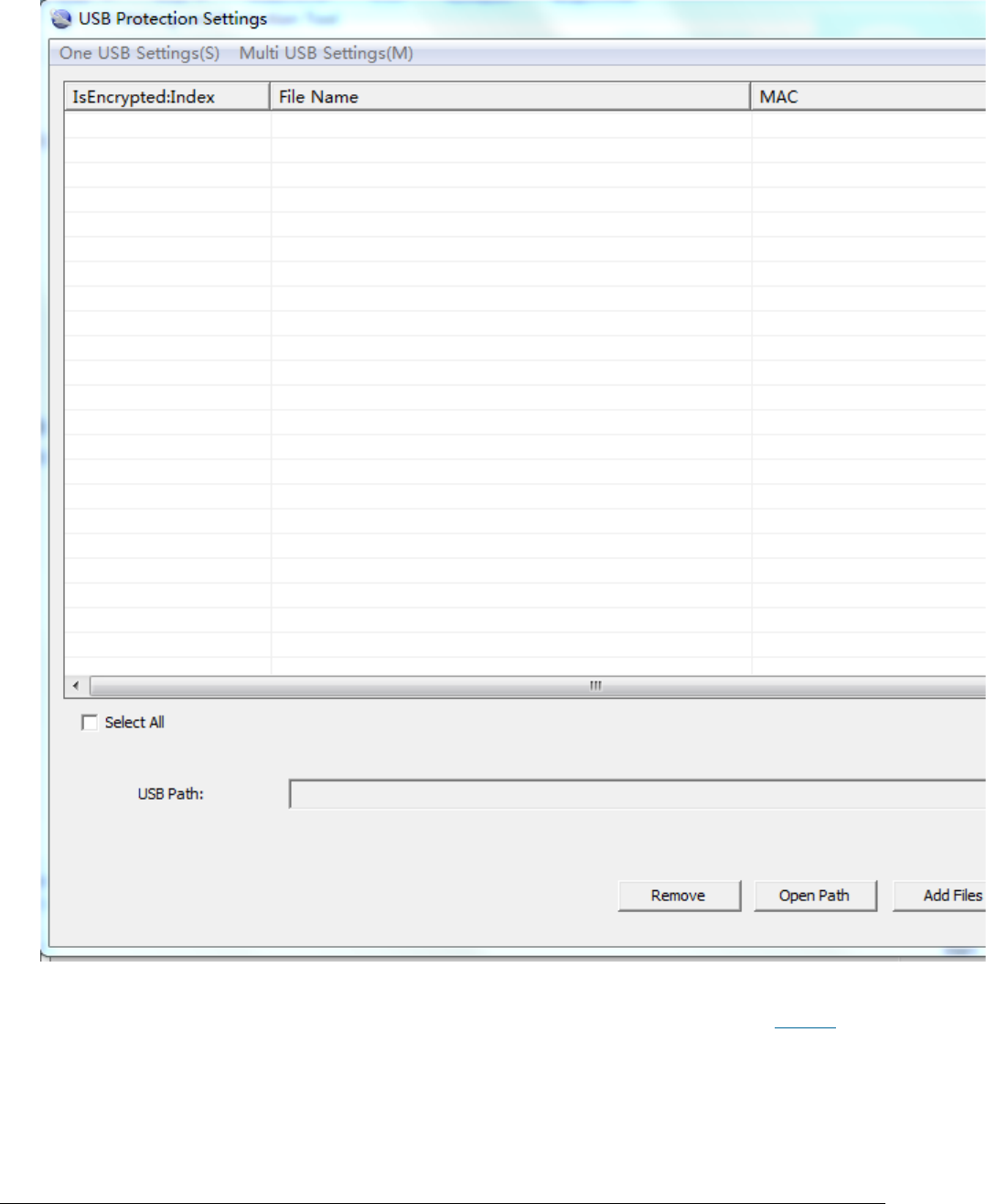
Issue 01 (2017-05-10)
Huawei Proprietary and Confidential
Copyright © Huawei Technologies Co., Ltd.
170
Figure 1 USB Protection Settings dialog box
4. Choose Multi USB Settings > Set USB Path and Security Policies. The Multi
USB Protection Settings dialog box is displayed. See the following Figure 2.
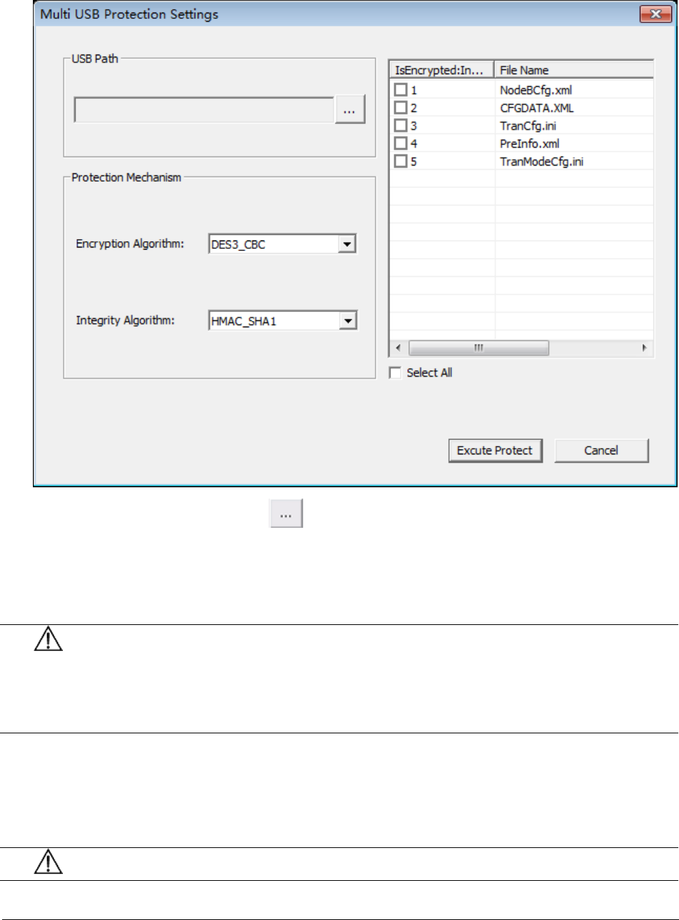
Issue 01 (2017-05-10)
Huawei Proprietary and Confidential
Copyright © Huawei Technologies Co., Ltd.
171
Figure 2 Multi USB Protection Settings dialog box
5. In the USB Path area, click and specify the root path on the local PC
for the folders storing files to be protected.
6. In the Protection Mechanism area, select algorithms as required from the
Encryption Algorithm and Integrity Algorithm drop-down lists.
NOTICE:
Encryption Algorithm can be set to DES3_CBC, AES192_CBC, or AES256_CBC.
Integrity Algorithm can be set to HMAC_SHA1 or HMAC_SHA256. You can choose
any encryption and integrity algorithms but the default ones are recommended.
7. Select the IsEncrypted:Index check box: In the file list area, if
IsEncrypted:Index is selected for a file, the system applies encryption
protection to this file. Otherwise, the system applies only integrity
protection to the file.
NOTICE:
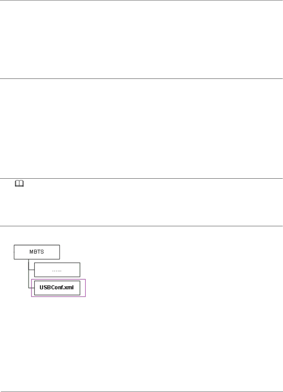
Issue 01 (2017-05-10)
Huawei Proprietary and Confidential
Copyright © Huawei Technologies Co., Ltd.
172
The files for which integrity and encryption protection must be applied are
described in Context. You must follow the rules; otherwise, deployments or
upgrades using an SD card will fail.
Encryption cannot be applied to version and patch software packages and
the Precfg.ini file.
Whether to apply encryption to other files depends on customers' security
requirements and whether the target version of a base station to be
upgraded supports SD card-based encryption.
8. Click Execute Protect.
The system applies encryption protection to files based on the specified
encryption algorithm and applies integrity protection to all files in the
current file list area based on the specified integrity algorithm.
Sizes of files remain the same before and after encryption because the
system uses a symmetrical encryption algorithm.
9. Click OK when a dialog box is displayed indicating that the integrity and
encryption protection is completed.
NOTE:
Do not delete or move the USBConf.xml file which has been automatically saved to a fixed
path. Otherwise, the base station cannot download files from the SD cards.
Ensure that the path of data configuration files in the USBConf.xml file is consistent
with the save path in the SD cards.
Figure 3 Save path for the USBConf.xml file
10.Delete source files on the SD cards. Copy the folder on the PC containing
the files that have been protected by using the tool to the SD cards. Note
that all the files in this folder must be copied.
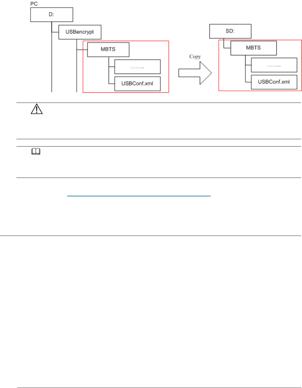
Issue 01 (2017-05-10)
Huawei Proprietary and Confidential
Copyright © Huawei Technologies Co., Ltd.
173
Figure 4 Copying files from the PC to the SD cards
NOTICE:
Do not change the directory structure in the folder when files are being
copied. Otherwise, deployments or upgrades using an SD card will fail.
NOTE:
If the base station software needs to be upgraded but no software package is contained in
the SD cards, manually copy the software package to the fixed directory.
Parent topic: Integrity and Encryption Protection on Files in MicroSD Cards
4.2.1.5.5 Saving Alarms/Events
This section describes how to save alarms and events to acquire system operating
status in real time.
Prerequisites
You have logged in to the local maintenance terminal (LMT) by using an account
with the required operation rights.
Procedure
1. On the menu bar of the LMT, click the Browse Alarm/Event or Query
Alarm/Event Log tab on the Alarm/Event tab page.
2. Right-click an alarm/event record to be saved and choose Save Selected to
save the record. Choose Save All to save all the alarm/event records.
Issue 01 (2017-05-10)
Huawei Proprietary and Confidential
Copyright © Huawei Technologies Co., Ltd.
174
3. You can also save all the records by clicking the Save All button on the
lower part of the Alarm/Event tab page.
NOTE:
You can click one record and drag the mouse to select multiple alarms/events.
Parent topic: FAQ
4.2.2 MML Site Deployment
Configuration Reference
This section provides references.
Parent topic: eAN3810A Deployment Guide
4.2.2.1 Configuration Reference
This section provides references.
Initial Configuration Using the LMT
This section describes the procedure for initial configuration of the eAN3810A
using the LMT.
Parent topic: MML Site Deployment
4.2.2.1.1 Initial Configuration Using the LMT
This section describes the procedure for initial configuration of the eAN3810A
using the LMT.
Prerequisites
You have installed the hardware and connected the cables.
You have logged in to the eAN3810A LMT. For detailed operations, see Configuring
Data on GUIs.

Issue 01 (2017-05-10)
Huawei Proprietary and Confidential
Copyright © Huawei Technologies Co., Ltd.
175
Context
Table 1 lists the data that needs to be planned and collected before the initial
configuration.
Table 1 Parameter preparation
Category
Related Command
Parameter Name
Value Sample
Description
eNodeB IP
ADD IPINTERFACE
IP Address
193.168.100.59
Used for
connection to
the S1
interface.
IP Address
172.253.254.59
Used for
connection to
the U2000.
S1-C
Interface
IP
ADD SCTPPEER
Peer IPv4 Address
200.100.109.100
Indicates the
first SCTP
peer IPv4
address for
signaling
channel setup.
This IP
address serves
as the first
peer IPv4
address for
automatic SCTP
link setup.
S1-U
Interface
IP
ADD
USERPLANEPEER
Peer IPv4 Address
200.100.109.109
Indicates the
user-plane
IPv4 address
of the peer
end.
U2000 IP
MOD IPOAM
Peer IPv4 Address
10.145.35.15
Indicates the
first SCTP
peer IPv4
address for
signaling
channel setup.
This IP
address serves

Issue 01 (2017-05-10)
Huawei Proprietary and Confidential
Copyright © Huawei Technologies Co., Ltd.
176
Table 1 Parameter preparation
Category
Related Command
Parameter Name
Value Sample
Description
as the first
peer IPv4
address for
automatic SCTP
link setup.
PLMN
ADD CNOPERATOR
Mobile country code
460
Indicates the
mobile country
code (MCC) of
the operator.
Mobile network code
90
Indicates the
mobile network
code (MNC) of
the operator.
Cell
Parameters
ADD CELL
Frequency band
60
Indicates the
frequency band
in which the
cell operates.
Uplink bandwidth
CELL_BW_N100(20M)
Downlink bandwidth
CELL_BW_N100(20M)
Cell FDD TDD indication
CELL_TDD
Indicates the
duplex mode of
the cell.
CELL_FDD
indicates the
FDD mode, and
CELL_TDD
indicates the
TDD mode.
SubframeAssignment
SA0
SpecialSubframePatterns
SSP7
Procedure
1. Add NE applications.
a. Run the ADD APP command to add an NE application.

Issue 01 (2017-05-10)
Huawei Proprietary and Confidential
Copyright © Huawei Technologies Co., Ltd.
177
Set the Application Type parameter to LTE(LTE).
2. Add IP addresses and routes (used for connection to the S1 interface and the
U2000).
a. Run the ADD IPINTERFACE command to add a device IP address used for
connection to the S1 interface.
Set the Interface Reference Type parameter to ETHERNET(Ethernet).
Set the IP Address parameter to the eNodeB IP address used for
connection to the S1 interface.
b. Run the ADD IPINTERFACE command to add a device IP address used for
connection to the U2000.
Set the Interface Reference Type parameter to ETHERNET(Ethernet).
Set the IP Address parameter to the eNodeB IP address used for
connection to the U2000.
c. Run the ADD ROUTE command to add a static IP route.
3. Add local and peer information of the data-plane and control-plane of the S1
interface.
a. Optional: Run the ADD LOGICALPORT command to add a transmission logical
port.
Before running the ADD LOGICALPORT command, run the LST LOGICALPORT
command to query whether an ADD LOGICALPORT record already exists. If so,
skip the previous substep.
b. Run the ADD TRANSPORTDEVICE command to add a transport device.
c. Run the ADD SCTPHOST command to add an SCTP host.
d. Run the ADD USERPLANEHOST command to add a user-plane host.
e. Run the ADD SCTPPEER command to add an SCTP peer.
Set the Peer IPv4 Address parameter to S1-C interface IP.
f. Run the ADD USERPLANEPEER command to add a user-plane peer.
Set the Peer IPv4 Address parameter to 200.100.109.109.
4. Add mapping relations required by the S1 interface.
Issue 01 (2017-05-10)
Huawei Proprietary and Confidential
Copyright © Huawei Technologies Co., Ltd.
178
a. Run the ADD LOGICALPORT2TRPDEV command to add a logical port to a
transport device.
b. Run the ADD SCTPHOST2TRPDEV command to add an SCTP host to a transport
device.
c. Run the ADD SCTPPEER2TRPDEV command to add an SCTP peer to a transport
device.
d. Run the ADD UPHOST2TRPDEV command to add a user-plane host to a transport
device.
e. Run the ADD UPPEER2TRPDEV command to add a user-plane peer to a transport
device.
5. Add configurations of operators and tracing areas (TAs).
a. Run the ADD CNOPERATOR command to add an operator.
Set the Mobile country code parameter to 460.
Set the Mobile network code parameter to 90.
b. Run the ADD CNOPERATORTA command to add TA configuration information.
6. Add an S1 object.
a. Run the ADD S1 command to add an S1 object.
7. Add sectors and cell antennas.
a. Run the ADD SECTOREQM command to add a set of sector equipment.
b. Run the ADD TXSECTORANTENNA command to add a transmit sector antenna.
c. Run the ADD RXSECTORANTENNA command to add a receive sector antenna.
NOTE:
Adding an antenna depends on the type of the added cell. Note that the Sector Equipment
No. must be consistent with the previous configurations.
8. Add cell and set sectors and operators for the cells.
a. Run the ADD CELL command to add a cell.
Set the Frequency band parameter to 60.
Set the Uplink bandwidth parameter to CELL_BW_N100(20M).
Set the Downlink bandwidth parameter to CELL_BW_N100(20M).

Issue 01 (2017-05-10)
Huawei Proprietary and Confidential
Copyright © Huawei Technologies Co., Ltd.
179
Set the Cell FDD TDD indication parameter to CELL_TDD.
Set the UL-DL subframe configurations parameter to SA0.
Set the Special subframe configurations parameter to SSP7.
b. Run the ADD EUCELLSECTOREQM command to add a set of sector equipment for
a cell.
c. Run the ADD CELLOP command to add a cell operator.
9. Change the eNodeB ID according to the plan and restart the eNodeB.
a. Run the MOD ENODEBFUNCTION command to modify an eNodeB function.
b. Run the RST BTSNODE command to restart the eNodeB.
10.Activate cells.
a. Run the ACT CELL command to activate a cell.
11.Connect to the U2000.
a. Run the MOD IPOAM command to modify the configuration of an IP
maintenance channel.
Set the Peer IPv4 Address parameter to 10.145.35.15.
Script
//Adding NE applications. If there is an LTE application, do not run the following command.
ADD APP:applicationNo=2,applicationType=LTE;
//Adding IP addresses and routes (used for connection to the S1 interface and the U2000)
ADD
IPINTERFACE:IPINTERFACENO=1,INTERFACEREFTYPE=ETHERNET,INTERFACEREF=0,IPADDRESS="193.168.100.59",
IPMASK="255.255.255.0";
ADD
IPINTERFACE:IPINTERFACENO=2,INTERFACEREFTYPE=ETHERNET,INTERFACEREF=0,IPADDRESS="172.253.254.59",
IPMASK="255.255.255.0";
ADD
ROUTE:ROUTENO=0,DESTIPADDR="200.100.109.0",DESTIPMASK="255.255.255.0",NEXTHOPIP="193.168.100.100
";
ADD
ROUTE:ROUTENO=1,DESTIPADDR="10.145.35.0",DESTIPMASK="255.255.255.0",NEXTHOPIP="172.253.254.254";
//Adding local and peer information of the data-plane and control-plane of the S1 interface
ADD LOGICALPORT: LOGICALPORTNO=0,INTERFACENO=0;
ADD TRANSPORTDEVICE:TRANSPORTDEVICENO=0;

Issue 01 (2017-05-10)
Huawei Proprietary and Confidential
Copyright © Huawei Technologies Co., Ltd.
180
ADD SCTPHOST:SCTPHOSTNO=0,IPINTERFACEREF=1,LOCALPORT=1024;
ADD USERPLANEHOST:USERPLANEHOSTNO=0,IPINTERFACEREF=1;
ADD SCTPPEER:SCTPPEERNO=0,PEERIPV4ADDR="200.100.109.100",PEERPORT=36412;
ADD USERPLANEPEER:USERPLANEPEERNO=0,PEERIPV4ADDR="200.100.109.109",REMOTEID="1";
//Adding mapping relations required by the S1 interface
ADD LOGICALPORT2TRPDEV:TRANSPORTDEVICENO=0,REFNO=0;
ADD SCTPHOST2TRPDEV:TRANSPORTDEVICENO=0,REFNO=0;
ADD SCTPPEER2TRPDEV:TRANSPORTDEVICENO=0,REFNO=0;
ADD UPHOST2TRPDEV:TRANSPORTDEVICENO=0,REFNO=0;
ADD UPPEER2TRPDEV:TRANSPORTDEVICENO=0,REFNO=0;
//Adding operators and TAs
ADD
CNOPERATOR:CNOPERATORID=0,CNOPERATORNAME="CMCC",CNOPERATORTYPE=CNOPERATOR_PRIMARY,MCC="460",MNC=
"90";
ADD CNOPERATORTA:TRACKINGAREAID=0,CNOPERATORID=0,TAC=1;
//Adding an S1 object
ADD
S1:S1ID=0,CNOPERATORID=0,TRANSPORTDEVICECFGFLAG=CP_UP_CFG,CPTRANSPORTDEVICENO=0,UPTRANSPORTDEVIC
ENO=0;
//Adding sectors and cell antennas
ADD SECTOREQM:sectorEqmNo=0;
ADD TXSECTORANTENNA:TXSECTORANTENNANO=0,SECTOREQMNO=0,TXBRANCHREF=0;
ADD RXSECTORANTENNA:RXSECTORANTENNANO=0,SECTOREQMNO=0,RXBRANCHREF=0;
ADD TXSECTORANTENNA:TXSECTORANTENNANO=1,SECTOREQMNO=0,TXBRANCHREF=1;
ADD RXSECTORANTENNA:RXSECTORANTENNANO=1,SECTOREQMNO=0,RXBRANCHREF=1;
//Adding cells and set sectors and operators for the cells
ADD
CELL:LOCALCELLID=0,CELLNAME="Cell0",FREQBAND=60,ULEARFCNCFGIND=NOT_CFG,DLEARFCN=61336,ULBANDWIDT
H=CELL_BW_N100,DLBANDWIDTH=CELL_BW_N100,CELLID=0,PHYCELLID=115,FDDTDDIND=CELL_TDD,ROOTSEQUENCEID
X=0,EMERGENCYAREAIDCFGIND=NOT_CFG,UEPOWERMAXCFGIND=NOT_CFG,SubframeAssignment=SA0,SpecialSubfram
ePatterns=SSP7;
ADD EUCELLSECTOREQM:LOCALCELLID=0,SECTOREQMID=0;
ADD CELLOP:LOCALCELLID=0,TRACKINGAREAID=0,MMECFGNUM=CELL_MME_CFG_NUM_0;
//Changing the ENODEBID according to the plan and restarting the eNodeB
MOD ENODEBFUNCTION:ENODEBID=586189;
RST BTSNODE:;
Issue 01 (2017-05-10)
Huawei Proprietary and Confidential
Copyright © Huawei Technologies Co., Ltd.
181
//Activating cells
ACT CELL:LOCALCELLID=0;
//Connecting to the U2000
MOD IPOAM:IPOAMNO=0,IPINTERFACEREF=2, PEERIPV4ADDR="10.145.35.15",PEERIPV4MASK="255.255.255.0";
Parent topic: Configuration Reference
5 Operation and Maintenance
General
Fault Management
Configuration Management
Performance Management
Security Management
Hardware Management
5.1 General
eAN3810A LMT User Guide
Parent topic: Operation and Maintenance
5.1.1 eAN3810A LMT User Guide
Overview
This document describes the functions and relevant components of the eAN3810A
Local Maintenance Terminal (LMT). It also provides instructions for performing
basic operation and maintenance (OM) tasks of the eAN3810A.
Product Version

Issue 01 (2017-05-10)
Huawei Proprietary and Confidential
Copyright © Huawei Technologies Co., Ltd.
182
NOTE:
Unless otherwise stated, "eNodeB", "Pico", "eAN", and "AirNode" in this document refer to the
3710 series AirNode.
The 3710 series AirNode is a base station that provides communications services
in Huawei eLTE-IoT solution. The following table lists the product name and
product version related to the 3710 series AirNode.
Product Name
Product Version
eAN3810A
V100R001C00
Intended Audience
This document is intended for:
Network engineers
System engineers
Field engineers
Organization
Introduction to the LMT
This chapter describes the functions, system requirements, and main window of
the local maintenance terminal (LMT).
Getting Started with the LMT
This section describes how to log in to and exit the LMT.
Running MML Commands
This section describes how to run man-machine language (MML) commands on the
local maintenance terminal (LMT) to operate and maintain the eAN3810A.
Managing Alarms/Events
This section describes how to manage alarms or events on the local maintenance
terminal (LMT) to analyze, locate, and clear faults.
Managing Message Tracing
By tracing messages, you can verify data and identify faults. After a message
tracing task is created, the traced messages can be browsed and saved.
FAQ
This section describes the common issues and solutions during the equipment
commissioning.

Issue 01 (2017-05-10)
Huawei Proprietary and Confidential
Copyright © Huawei Technologies Co., Ltd.
183
Parent topic: General
5.1.1.1 Introduction to the LMT
This chapter describes the functions, system requirements, and main window of
the local maintenance terminal (LMT).
Definitions of the LMT
This section provides definitions of the LMT, LMT PC.
Functions of the LMT
The LMT is mainly used to locally locate and fix faults.
System Requirements for LMT Installation
This section describes the system requirements for the local maintenance
terminal (LMT) installation.
Components of the LMT Main Window
This section describes the components of the local maintenance terminal (LMT)
main window and the functions of each component.
Parent topic: eAN3810A LMT User Guide
5.1.1.1.1 Definitions of the LMT
This section provides definitions of the LMT, LMT PC.
LMT
The LMT is a logical concept. It refers to an operation and maintenance O&M
terminal that has the Huawei Local Maintenance Terminal software installed and
connects to the O&M network for an NE. You can operate and maintain NEs using
the LMT.
LMT PC
The LMT PC is a hardware concept. It refers to a computer where the Huawei Local
Maintenance Terminal software is installed.
Parent topic: Introduction to the LMT

Issue 01 (2017-05-10)
Huawei Proprietary and Confidential
Copyright © Huawei Technologies Co., Ltd.
184
5.1.1.1.2 Functions of the LMT
The LMT is mainly used to locally locate and fix faults.
Use the LMT to operate and maintain an eAN3810A in the following scenarios:
Use the LMT to locally maintain the eAN3810A.
When alarms are generated on the eAN3810A, use the LMT to locate and fix the
faults.
The LMT provides a Graphical User Interface (GUI), which helps users operate and
maintain the eAN3810A on the Web. The LMT implements the following local OM
functions:
Executes man-machine language (MML) commands
Manages alarms and events
Traces messages
Parent topic: Introduction to the LMT
5.1.1.1.3 System Requirements for LMT
Installation
This section describes the system requirements for the local maintenance
terminal (LMT) installation.
Hardware Configuration Requirements
Table 1 lists the hardware configuration requirements for the LMT PC.
Table 1 Hardware configuration requirements
Item
Recommended Configuration
Minimum Configuration
CPU
2.8 GHz or higher
866 MHz
RAM
1 GB
512 MB
Hard disk
80 GB
10 GB

Issue 01 (2017-05-10)
Huawei Proprietary and Confidential
Copyright © Huawei Technologies Co., Ltd.
185
Table 1 Hardware configuration requirements
Item
Recommended Configuration
Minimum Configuration
Video card resolution
1024 x 768 or higher
1024 × 768
CD-ROM drive
-
-
Network interface card
10 Mbit/s or 100 Mbit/s
10 Mbit/s
Accessories
A keyboard, a mouse, a
modem, an audio adapter, and
a sound box
A keyboard and a mouse
Software Configuration Requirements
Table 2 describes the software configuration requirements for the LMT PC.
Table 2 Software configuration requirements
Item
Recommended Configuration
Operating system
Microsoft Windows 2003 with patch
KB938397
Microsoft Windows 2008
Microsoft Windows Vista
Microsoft Windows 7
NOTE:
The LMT only supports web browsers and 32-bit
operating systems.
Default language of the operating system
English (United States)
Web browse
Internet Explorer 9 (recommended)
Internet Explorer 10 (recommended)
Internet Explorer 11 (recommended)
Firefox 30.X or later (X indicates a
digit, recommended)
NOTE:

Issue 01 (2017-05-10)
Huawei Proprietary and Confidential
Copyright © Huawei Technologies Co., Ltd.
186
Table 2 Software configuration requirements
Item
Recommended Configuration
Set the security level of the web browser to medium or
low. Otherwise, the LMT menus cannot be viewed.
Only support IE9 and later version.
Only support Firefox 30.X and later version.
On the Advanced tab page in the Internet Options
dialog box, select all check boxes under HTTP1.1
settings.
Port Requirements
Use the Web to access the eAN3810A for OM. If a firewall exists between the
eAN3810A and the LMT PC, ports 20, 21, and 80 must be enabled on the firewall.
If Hypertext Transfer Protocol Secure (HTTPS) needs to be used, ports 20, 21,
and 443 must be enabled on the firewall.
NOTE:
Ports 20 and 21 are used for the File Transfer Protocol (FTP). They need to be enabled when
files are transferred using the FTP.
Port 80 is used for the Hypertext Transfer Protocol (HTTP) by default. That is, the port is
used for a web server by default.
Port 443 is used for the HTTPS by default.
HTTP cannot ensure secure access. In HTTP-based connection mode, the data exchanged between
the LMT and the eAN3810A is vulnerable to interception. Therefore, the LMT can use only HTTPS
to access the eAN3810A.
Communication Capability Requirements
The LMT PC must support TCP/IP protocols.
The minimum effective network bandwidth for the LMT is 512 kbit/s. The
recommended bandwidth is 2 Mbit/s or higher.
NOTE:
The network bandwidth limits the web page opening speed. If the recommended effective
bandwidth is provided, the LMT runs quickly. If the minimum effective bandwidth is provided,
all the functions can be performed, but the LMT runs slowly.
The effective bandwidth is the bandwidth occupied by the LMT. If multiple applications
compete for this bandwidth, the LMT may run slowly even if a 2 Mbit/s bandwidth is provided.
Parent topic: Introduction to the LMT
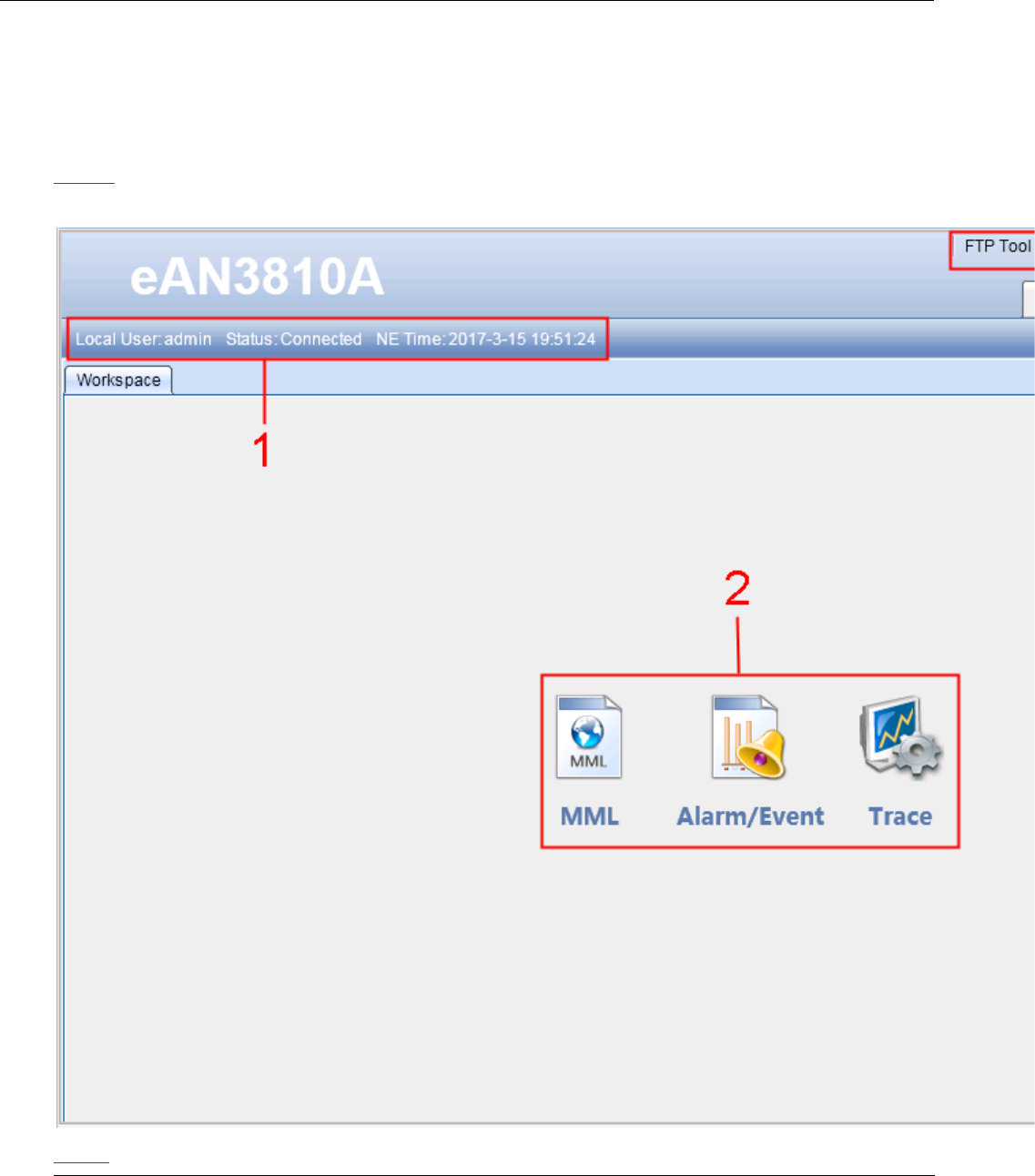
Issue 01 (2017-05-10)
Huawei Proprietary and Confidential
Copyright © Huawei Technologies Co., Ltd.
187
5.1.1.1.4 Components of the LMT Main Window
This section describes the components of the local maintenance terminal (LMT)
main window and the functions of each component.
Main Window
Figure 1 shows the LMT main window.
Figure 1 LMT main window
Table 1 describes the components of the LMT main window.

Issue 01 (2017-05-10)
Huawei Proprietary and Confidential
Copyright © Huawei Technologies Co., Ltd.
188
Table 1 Components of the LMT main window
No.
Component
Field
Description
1
Status bar
-
Displays the user
type, user name,
connection status,
and NE time.
2
Functions
MML
Used to run man-
machine language
(MML) commands. For
details, see Basic
Concepts Related to MML
Commands.
Alarm/Event
Used to query active
alarms or events,
alarm or event logs,
and alarm or event
configurations.
Trace
Used to trace
messages , see
Managing Message
Tracing.
FTP Tool
Used to download the
FTP tool.
Click FTP Tool. A
File Download -
Security Warning
dialog box is
displayed.
Click Save to
save the FTP
server software
SFTPServer.exe to
the computer
where the LMT is
installed.
NOTE:
The default user name is
admin, and the default

Issue 01 (2017-05-10)
Huawei Proprietary and Confidential
Copyright © Huawei Technologies Co., Ltd.
189
Table 1 Components of the LMT main window
No.
Component
Field
Description
password is hwbs@com.
Password
Used to change the
password.
1. Click Password.
A Password
dialog box is
displayed.
2. Set Old
Password, New
Password, and
Confirm
Password.
3. Click OK . The
password is
changed.
About
Displays the version
information.
System Settings
Settings Used to set
the automatic logout
time.
1. Click System
Settings. A
System Settings
dialog box is
displayed.
2. Set Auto logout
if no operation
within (s).
3. Click Submit.
The system
setting is
complete.
Logout
Used to log out of
the LMT.
4
Others
Help
Used to open online
Issue 01 (2017-05-10)
Huawei Proprietary and Confidential
Copyright © Huawei Technologies Co., Ltd.
190
Table 1 Components of the LMT main window
No.
Component
Field
Description
help files.
Layout
Used to indicate the
layout management
function. Four
window layouts are
available: cascade,
tile horizontal,
tile vertical, and
dock window.
NOTE:
The LMT periodically checks for application changes. Therefore, the message display time may
be later than the time when an application change takes effect.
The Firefox browser does not support window layout changes.
Online Help
The LMT provides two types of online help:
LMT help
MML help
Table 2describes the online help of the LMT.
Table 2 Online help of the LMT
Name
Description
Startup Operation
LMT help
Provides the following
information:
LMT user guide
Alarm details
Event details
If you are using Internet
Explorer:
Press F1 or click Help in
the LMT main window to
display LMT help topics.
Press F1 in a displayed
dialog box to display the
help topics about the
dialog box.
If you are using a Firefox
Issue 01 (2017-05-10)
Huawei Proprietary and Confidential
Copyright © Huawei Technologies Co., Ltd.
191
Table 2 Online help of the LMT
Name
Description
Startup Operation
browser, click Help in the
LMT main window to display
the help information.
MML help
Provides the following
information about an MML
command:
Function
Notes
Parameter ID
Example
Output of a query command
Enter an MML command in the
Command Input text box.
Press Enter or click
Assist , and then click the
Help tab. The help
information about the
command is displayed on the
tab page.
Parent topic: Introduction to the LMT
5.1.1.2 Getting Started with the LMT
This section describes how to log in to and exit the LMT.
NOTE:
A minimum of 1 GB free space is required to ensure that the LMT runs correctly.
Logging In to the LMT
This section describes how to log in to the LMT.
Logging Out of the LMT
This section describes how to log out of the LMT.
Managing User Accounts
Managing user accounts involves managing the accounts and passwords of users.
Parent topic: eAN3810A LMT User Guide
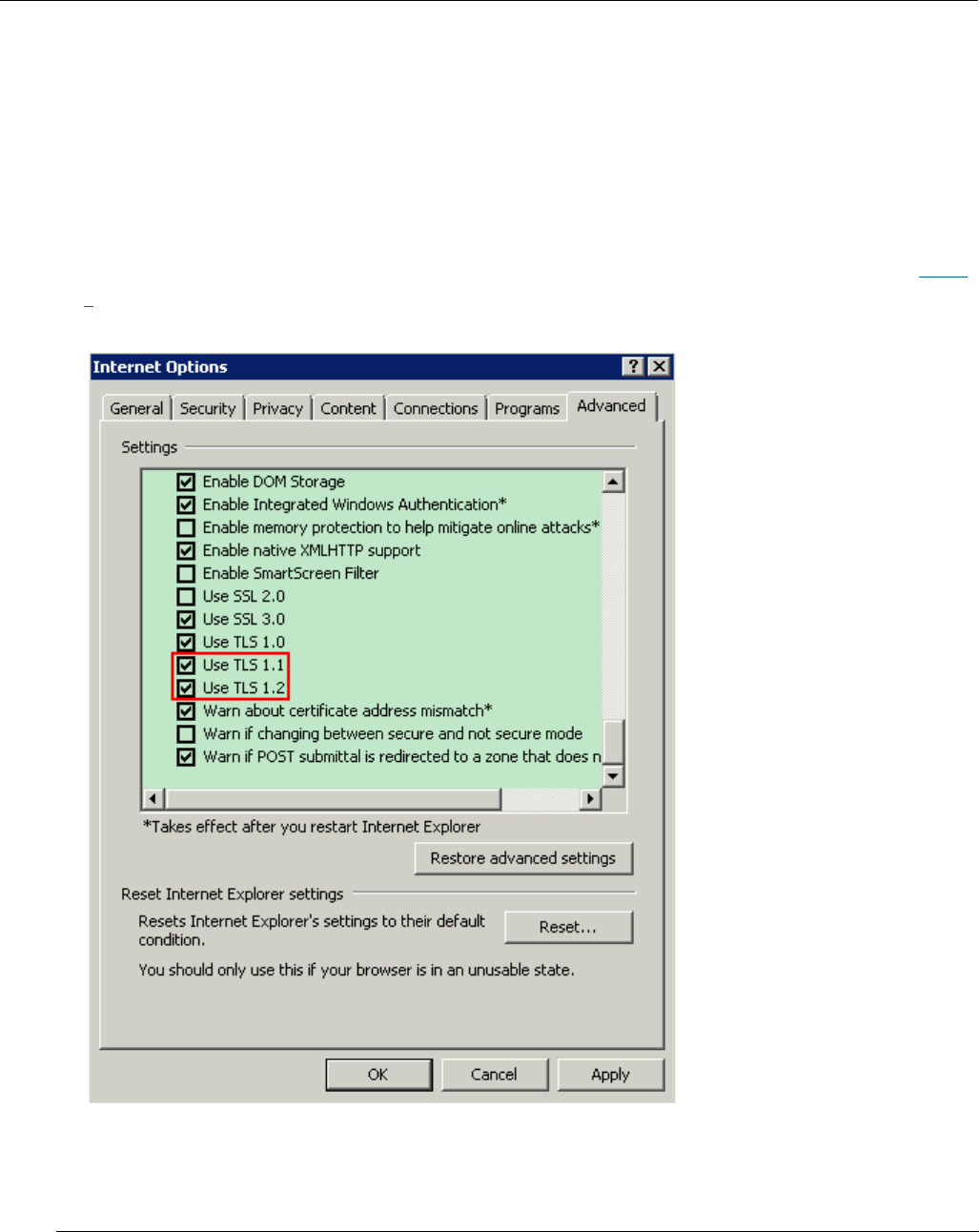
Issue 01 (2017-05-10)
Huawei Proprietary and Confidential
Copyright © Huawei Technologies Co., Ltd.
192
5.1.1.2.1 Logging In to the LMT
This section describes how to log in to the LMT.
Prerequisites
The network connection between the LMT and eAN3810A server has been
established.
When the IE is used for LMT login, first set IE's Internet Options before
logging, check the "TLS1.1" and "TLS1.2" in the "Advanced" , as shown in Figure
1.
Figure 1 IE's Internet Options
When the Firefox is used for LMT login, first set Firefox's encryption method
before logging, enter "about:config" and return, then find the item
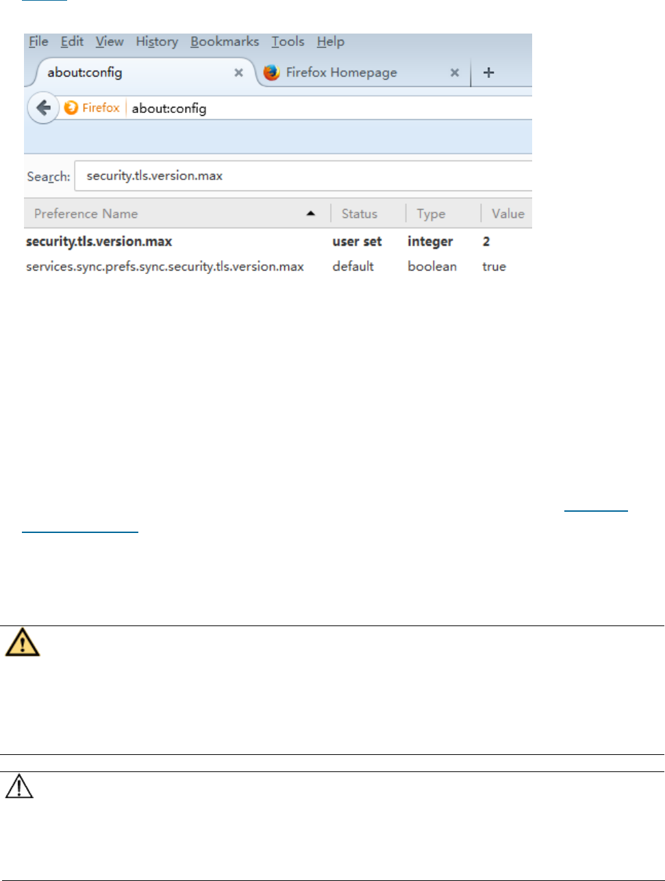
Issue 01 (2017-05-10)
Huawei Proprietary and Confidential
Copyright © Huawei Technologies Co., Ltd.
193
"security.tls.version.max" and change its value to "2" or "3" , as shown in
Figure 2.
Figure 2 Firefox encryption method
Context
There is two types of LMT users: Local User and Domain User.
A maximum of 15 local users can log in to the LMT at the same time.
By default, the LMT is accessed using the HTTPS policy. If HTTP is entered in
a web browser, the HTTP is automatically changed into HTTPS before logging in
to the LMT.
If the colors of the LMT main page cannot be displayed when the Internet
Explorer is used, perform operations according to instructions in LMT Colors
Cannot Be Displayed.
After the O&M channel between the NE and eSight server is established, you
can log in to the NE using the eSight server. The network connection between
the LMT and eAN3810A server has been established.
CAUTION:
Do not change the system time or time zone of the LMT PC when the LMT is running.
Otherwise, a critical fault may occur in the system. If the system time or time
zone has to be changed, you must perform the operation after logging out of the
LMT.
NOTICE:
If the pop-up blocker is enabled when the Firefox browser is used for LMT
login, the LMT cannot be logged in. To avoid this problem, choose Settings.

Issue 01 (2017-05-10)
Huawei Proprietary and Confidential
Copyright © Huawei Technologies Co., Ltd.
194
In the displayed Options dialog box, clear the Block pop-up windows check box
on the Content tab page.
The refresh function of the browser cannot be used on the LMT. If you use the
refresh function in the LMT main page, the LMT main page is closed. If you
use the refresh function on the monitoring page, a script error occurs.
When the Internet Explorer is used for LMT login, do not change the
properties of the cache file folders. Otherwise, the Internet Explorer is
automatically refreshed, resulting in an error in the LMT main page.
If you use Internet Explorer to log in to the LMT and choose StartRun to
start File Transfer Protocol (FTP) services, the LMT main window is replaced
with the login dialog box of the FTP server. To prevent this problem, set
Internet Explorer as follows: In Internet Explorer, choose Tools Internet
Options, and deselect Reuse windows for launching shortcuts under Browse on
the Advanced tab page.
Before you use the web LMT to upgrade or roll back an eAN3810A, clear the
browser's buffer and cookies.
If you press ALT+ , the LMT main window may experience an error. In this
case, press ALT + to restore the window settings. If the window settings
cannot be restored, close the browser and log in to the web LMT again.
Procedure
1. Connect the web LMT to the eAN3810A.
2. In the address box of the browser, enter the IP address of the vUSN for
local maintenance. The default IP address is 192.168.0.100.
3. Click Go. The Local Maintenance Termina login window is displayed.Figure 3
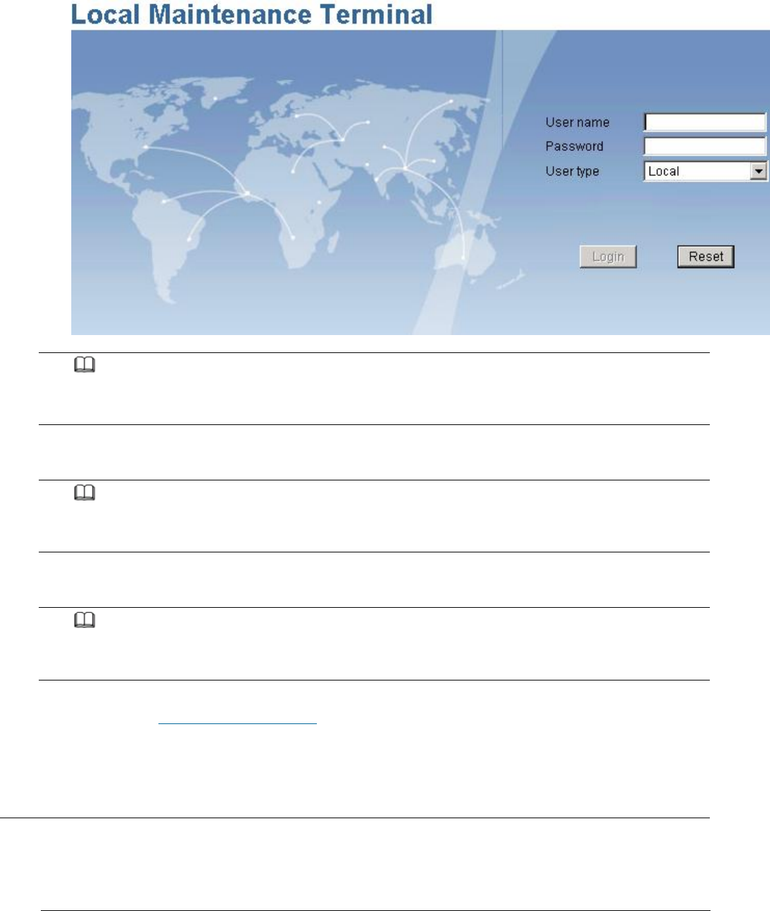
Issue 01 (2017-05-10)
Huawei Proprietary and Confidential
Copyright © Huawei Technologies Co., Ltd.
195
Figure 3 Local Maintenance Termina login window
NOTE:
During the login, the system checks the compatibility view settings of the browser. To use
the optimum LMT configurations, perform operations as prompted.
4. Enter the user name and password. Set User type to Local.
NOTE:
By default, the user name is admin and the password is hwbs@com . Both are case-sensitive.
Change the password after you log in to the LMT.
5. Click Login
NOTE:
If the login fails, click Reset. Enter the user name and password again to log in. If the
login fails again, check whether the connection between the LMT and eAN3810A is normal.
Parent topic: Getting Started with the LMT
5.1.1.2.2 Logging Out of the LMT
This section describes how to log out of the LMT.
Procedure
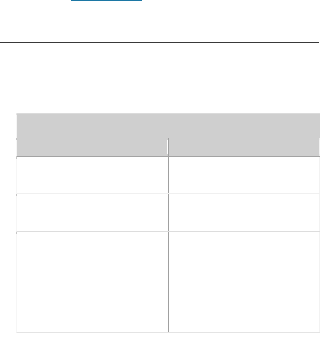
Issue 01 (2017-05-10)
Huawei Proprietary and Confidential
Copyright © Huawei Technologies Co., Ltd.
196
1. Click Logout on the upper right corner of the LMT main page. The Confirm
dialog box is displayed.
2. Click Yes. The LMT is disconnected from the current NE and the login window
is displayed.
3. Close the Internet Explorer browser to log out of the LMT.
Parent topic: Getting Started with the LMT
5.1.1.2.3 Managing User Accounts
Managing user accounts involves managing the accounts and passwords of users.
Managing Accounts
Table 1 describes the concepts related to user accounts.
Table 1 Concepts related to user accounts
Name
Description
User type
LMT users are local users, which are
managed by the LMT. The default user is
admin.
User account
The LMT user account is a default system
account with the user name being admin and
the default password being hwbs@com.
Login password
Login password involves the password
policies, initial password, and password
change permissions, which are described as
follows:
A user must enter the correct user name
and password when logging in to the LMT.
The user can operate the base station
only after being verified.
The login password of admin user is set
when the base station application

Issue 01 (2017-05-10)
Huawei Proprietary and Confidential
Copyright © Huawei Technologies Co., Ltd.
197
Table 1 Concepts related to user accounts
Name
Description
software is installed.
Managing Login Passwords
Managing login passwords involves setting and viewing password policies and
changing the passwords of accounts.
Table 2 describes the tasks involved in managing login passwords.
Table 2 Tasks involved in managing login passwords
Task
Description
Setting password policies
Function
Password policies define how
to set login passwords.
NOTE:
Password policies define the
minimum password length and
complexity. If a password does not
meet the required minimum
password length or complexity,
this password cannot take effect.
Password policies define the
maximum number of times an
incorrect password can be entered.
The default number of attempts is
three. If this threshold is exceeded,
the LMT will be locked and then
unlocked 30 minutes later. You
can specify the length of this
duration in the password policies.
Procedure
Run the MOD PASSWORDPOLICY
command on the U2000 to set
login password policies.
Viewing password policies
Function
Users can view password
policies before setting
correct login passwords.

Issue 01 (2017-05-10)
Huawei Proprietary and Confidential
Copyright © Huawei Technologies Co., Ltd.
198
Table 2 Tasks involved in managing login passwords
Task
Description
Procedure
Run the LST PASSWORDPOLICY
command to view password
policies.
Changing the password of a
current user account
Function
The current user can change
its own password after
login. The new password
takes effect upon the next
login.
Procedure
Click Password on the
upper right side of the
toolbar in the LMT main
window. A Password dialog
box is displayed.
Fill in the Old Password,
New Password, and Confirm
Password text boxes, and
click OK.
NOTE:
Exercise caution when changing the password of the admin user. If you forget the password,
contact Huawei technical support.
Parent topic: Getting Started with the LMT
5.1.1.3 Running MML Commands
This section describes how to run man-machine language (MML) commands on the
local maintenance terminal (LMT) to operate and maintain the eAN3810A.
Basic Concepts Related to MML Commands
This following describes MML command functions and formats, and types of
operations performed using MML commands.

Issue 01 (2017-05-10)
Huawei Proprietary and Confidential
Copyright © Huawei Technologies Co., Ltd.
199
Running a Single MML Command
You can run man-machine language (MML) commands one at a time to perform routine
operation and maintenance.
Setting Parameters
You can set parameters in the MML Settings dialog box.
Parent topic: eAN3810A LMT User Guide
5.1.1.3.1 Basic Concepts Related to MML
Commands
This following describes MML command functions and formats, and types of
operations performed using MML commands.
Functions of MML Commands
You can operate and maintain the entire NE using MML commands. The MML commands
enable you to perform the following operations:
Alarm management
NE configuration, maintenance, and management
Transmission configuration, maintenance, and management
System management
Service configuration, maintenance, and management
Formats of MML Commands
The format of an MML command can be "Command Word: Parameter Name=Value;".
The command word is mandatory, whereas the parameter name and value are optional.
MML command with a command word and parameters: SET ALMCFG: AID=25600,
SHLDFLG=UNSHIELDED;
MML command with only a command word: DSP VER:;
NOTE:
The value of a string or password parameter must not contain +++ (start characters of an MML
command output), ---END (end characters of an MML command output), or the following characters:
< > ! ? \ / ; , = + % * " ' |

Issue 01 (2017-05-10)
Huawei Proprietary and Confidential
Copyright © Huawei Technologies Co., Ltd.
200
Types of Operations Performed Using MML Commands
The MML command word format is denoted as Action + Object. Table 1 describes the
most commonly used MML commands.
Table 1 Most commonly used MML commands
Action
Meaning
ACT
Activate
ADD
Add
BKP
Back up
DLD
Download
DSP
Display (used to query dynamic
information)
LST
List (used to query static information)
MOD
Modify
RMV
Remove
RST
Reset
SET
Set
STP
Stop or close
STR
Start or open
ULD
Upload
Components of the MML Command Window
This section describes the components of the MML command window.
In the LMT main window, click the MML tab. Figure 1shows the MML command window.
Issue 01 (2017-05-10)
Huawei Proprietary and Confidential
Copyright © Huawei Technologies Co., Ltd.
201
Figure 1 MML command window
NOTE:
For details about MML commands and their related parameters, see the MML command help.
Table 2 describes the components of the MML command window.
Table 2 Components of the MML command window
No.
Field
Description
1
MML navigation tree
You can choose a command group from the navigation
tree.
2
Common Maintenance
tab
Displays the output of an MML command.
3
Operation Records
tab
Displays information about all the commands that
have been executed by the user.
4
Help tab
Displays the help topics for an MML command.
5
Command output
handling options
You can click Auto Scroll, and Clear All.
6
Pane for manual
input of an MML
command
Displays the manually entered command and parameter
values.
7
Command History
text box
Records all the commands and parameters a user
enters during one session.

Issue 01 (2017-05-10)
Huawei Proprietary and Confidential
Copyright © Huawei Technologies Co., Ltd.
202
Table 2 Components of the MML command window
No.
Field
Description
8
Command text box
Displays all the MML commands of the system. You can
select an MML command from the drop-down list or
enter the command directly.
9
Area for setting
parameters of an
MML command
Displays all parameters that can be set in an MML
command entered in the Command text box. The
parameters in red are mandatory and the parameters
in black are optional, as shown in Figure 1.
Parent topic: Running MML Commands
5.1.1.3.2 Running a Single MML Command
You can run man-machine language (MML) commands one at a time to perform routine
operation and maintenance.
Prerequisites
You have logged in to the web local maintenance terminal (LMT) by using an
account with the required operation rights.
Context
You can use one of the following four methods to run a single MML command:
Enter an MML command in the Command text box.
Select an MML command from the Command History drop-down list box.
Choose an MML command in the MML Commands navigation tree.
To manually input an MML command, enter or copy it into the pane for manual
input of commands.
Procedure
Enter an MML command in the Command text box.
Issue 01 (2017-05-10)
Huawei Proprietary and Confidential
Copyright © Huawei Technologies Co., Ltd.
203
1. Enter an MML command in the Command text box. When typing an MML command,
you can select the command from the drop-down list.
2. Press Enter or click Assist. The parameters related to the command are
displayed in the area for setting the parameters of the command.
3. Set the related parameters.
4. Press F9 or click Exec to run the command. The MML command output is
displayed on the Common Maintenance tab page.
Select an MML command from the Command History drop-down list box.
1. Select a historical command from the Command History drop-down list box.
Press F7 or click to select the previous command, and press F8 or
click to select the next command. The parameters related to the
command are displayed in the area for setting the parameters of an MML
command.
2. Set the related parameters.
3. Press F9 or click Exec to run the command. The MML command output is
displayed on the Common Maintenance tab page.
Choose an MML command in the MML Commands navigation tree.
1. Choose and double-click an MML command in the MML Commands navigation tree.
2. Set the related parameters.
3. Press F9 or click Exec to run the command. The MML command output is
displayed on the Common Maintenance tab page.
To manually input an MML command, enter or copy it into the pane for manual
input of commands.
1. Manually enter or copy an MML command with complete parameter settings
into the pane.
2. Press F9 or click Exec to run the command. The MML command output is
displayed on the Common Maintenance tab page.
NOTE:
The parameters in red are mandatory, and those in black are optional.
To obtain information about a parameter, move the cursor to the input box of the parameter.
When you run an MML command with a time parameter, the default value of the time parameter
is the time of the eAN3810A required, you can change the value.
If an MML command fails to be executed, the execution result is displayed in red on the
Common Maintenance tab page.
The recommended zoom ratio for the web page is 100%.
Issue 01 (2017-05-10)
Huawei Proprietary and Confidential
Copyright © Huawei Technologies Co., Ltd.
204
Parent topic: Running MML Commands
5.1.1.3.3 Setting Parameters
You can set parameters in the MML Settings dialog box.
Prerequisites
You have logged in to the LMT using an account with the required operation
rights.
Procedure
1. At the upper right corner of the MML tab page, click Settings.
The Settings dialog box is displayed.
2. Set parameters in the System Settings and Settings areas.
NOTE:
The parameter settings in the System Settings and Settings are stored at the server end and
client end, respectively. Therefore, after the base station restarts, the parameter settings
in System Settings resumes to the default value but the parameter settings in Settings
remain unchanged.
3. Click OK. The settings are complete.
Parent topic: Running MML Commands
5.1.1.4 Managing Alarms/Events
This section describes how to manage alarms or events on the local maintenance
terminal (LMT) to analyze, locate, and clear faults.
Basic Concepts Related to Alarms/Events
Before managing eAN3810A alarms or events, you must understand the basic
concepts related to eAN3810A alarms or events, including their definitions, logs,
severity levels, and network management types.
Handling Alarms/Events
Handling alarms or events involves the following actions: browsing active alarms

Issue 01 (2017-05-10)
Huawei Proprietary and Confidential
Copyright © Huawei Technologies Co., Ltd.
205
or events, querying alarm or event logs, querying alarm or event configurations,
manually clearing alarms or events, and querying alarm or event handling
suggestions.
Parent topic: eAN3810A LMT User Guide
5.1.1.4.1 Basic Concepts Related to
Alarms/Events
Before managing eAN3810A alarms or events, you must understand the basic
concepts related to eAN3810A alarms or events, including their definitions, logs,
severity levels, and network management types.
Alarm or Event Categories
This section describes the basic concepts related to alarms and events.
Alarm
An alarm is generated if the hardware(for example, a VM) is faulty or a major
function fails. An alarm has a higher severity than an event. Based on the
status of the faults, alarms can be categorized into active alarms and clear
alarms.
If a fault is cleared, the status of the alarm changes to clear. This type of
alarm is called a clear alarm.
If a fault is not cleared, the status of the alarm remains active. This type
of alarm is called an active alarm.
NOTE:
You can search a database for clear alarms.
If an alarm is cleared after you switch from the alarm query page to another page, the
information about this alarm is not displayed on the alarm query page when you switch back to
the alarm query page. This is because the alarms are queried again when you switch back to
the alarm query page and cleared alarms are not displayed on the page.
Event
An event notifies users of important information when the system is operating
correctly. Users do not need to handle an event.
Severity

Issue 01 (2017-05-10)
Huawei Proprietary and Confidential
Copyright © Huawei Technologies Co., Ltd.
206
The alarm severity indicates the degree to which an alarm affects system
performance. Based on the degree, all alarms can be categorized into four types:
Critical, Major, Minor, and Warning.
Table 1describes alarm severities and provides handling suggestions for each.
Table 1 Alarm severities and handling suggestions
Severity
Definition
Handling Suggestion
Critical
Service-affecting condition. Critical alarms
require immediate attention, and must be
cleared immediately. For example, faulty
devices need to be immediately repaired or
unavailable resources need to be immediately
restored.
These alarms must be
cleared immediately.
Otherwise, the
system may fail.
Major
Degradation of service, but not a complete loss
of service. Major alarms must be cleared during
working hours. For example, faults that affect
device performance or resource performance must
be fixed during working hours, and their alarms
must be cleared.
These alarms must be
cleared in a timely
manner. Otherwise,
some important
functions cannot be
implemented.
Minor
Non-service-affecting condition. Minor alarms
must be handled within a certain time period to
avoid severer problems.
These alarms help
maintenance
personnel locate and
clear potential
faults before they
become problems.
Warning
Potential service-affecting condition. Warning
alarms must be handled based on the problems
causing the alarms.
These alarms help
maintenance
personnel determine
the operating status
of the system.
Network Management Alarm Type
This section describes alarm types from the perspective of the network
management.
Based on network management standards, alarms are categorized as follows:
Power alarm: related to the power system.

Issue 01 (2017-05-10)
Huawei Proprietary and Confidential
Copyright © Huawei Technologies Co., Ltd.
207
Environment alarm: related to environment of the equipment room.(such as,
temperature, humidity and entrance guard)
Signaling alarm: related to service signaling.
Trunk alarm: related to the transport subsystem.
Hardware alarm: related to VM.(such as, clock, CPU)
Software alarm: related to software.
Running alarm: related to the running of the system.
Communication alarm: related to the communication system.(Communications
between the host and OMU)
Quality of service (QoS) alarm: related to QoS.
Integrity violation alarm: a type of security alarm, which indicates that
information may be modified, added, or removed without permission.
Operation violation alarm: a type of security alarm, which indicates that
services are unavailable or unreachable due to factors such as incorrect
operations or faults.
Physical violation alarm: a type of security alarm, which indicates that
physical resources are unavailable due to possible attacks.
Security violation alarm: a type of security alarm, which indicates that the
security service or security mechanism detects that the system is
experiencing attacks.
Time domain violation alarm: a type of security alarm, which indicates that
unexpected events have occurred.
Processing error alarm: related to processing errors.
Alarm Flags
Four alarm flags are provided: flag indicating whether an alarm is to be
reported to the alarm box, alarm masking flag, alarm modification flag, and
alarm clearance flag.
Flag Indicating Whether an Alarm Is to Be Reported to the Alarm Box
This flag controls whether an alarm is to be reported to the alarm box. The flag
status is as follows:
Report
In this status, the local maintenance terminal (LMT) instructs the alarm box
to generate audible and visual alarms.

Issue 01 (2017-05-10)
Huawei Proprietary and Confidential
Copyright © Huawei Technologies Co., Ltd.
208
Not report
In this status, the web LMT does not instruct the alarm box to generate
audible and visual alarms when alarms are reported or the alarm status is
changed.
NOTE:
This flag applies only to fault alarms, but not to event alarms.
An alarm can be reported to the alarm box only if this flag is set to Report for
the alarm and the alarm severity is greater than or equal to the severity
specified for alarm reporting to the alarm box.
Alarm Masking Flag
This flag controls whether an alarm is to be masked. The flag status is as
follows:
Mask
A VM does not report an alarm for which this flag is set to Mask to the
network management system (NMS) or the alarm box. The server does not record
the alarm log.
Not mask
A VM reports an alarm for which this flag is set to Not mask to the NMS and
the alarm box. The server records the alarm log.
Alarm Modification Flag
This flag indicates whether the alarm configuration has been modified, which
facilitates the query and restoration of the configuration. The flag status is
as follows:
Modified
After an MML command is executed to modify the alarm configuration, this flag
is set to Modified.
Not modified
If the default alarm configuration is used or an MML command is executed to
restore the default alarm configuration, this flag is set to Not modified.
Alarm Clearance Flag
This flag indicates whether a fault alarm has been cleared. The flag status is
as follows:
Not cleared

Issue 01 (2017-05-10)
Huawei Proprietary and Confidential
Copyright © Huawei Technologies Co., Ltd.
209
The fault alarm has not been cleared yet.
Cleared
A clear alarm has been reported, indicating that the fault alarm has been
cleared.
Parent topic: Managing Alarms/Events
5.1.1.4.2 Handling Alarms/Events
Handling alarms or events involves the following actions: browsing active alarms
or events, querying alarm or event logs, querying alarm or event configurations,
manually clearing alarms or events, and querying alarm or event handling
suggestions.
Setting Alarm/Event Query Properties
Setting alarm or event query properties specifies the settings in an alarm or
event display dialog box. You can customize a color for each alarm or event
severity and set alarm or event display columns.
Browsing Active Alarms/Events
Normal alarms and events reported to the local maintenance terminal (LMT) are
displayed on the Browse Alarm/Event tab page in real time. You can view the
detailed information about alarms and events to determine the real-time running
status of the system.
Querying Alarm/Event Logs
You can query the historical alarms or events from the alarm or event logs to
determine the previous running status of the equipment.
Saving Alarms/Events
You can save all or part of the alarm or event records displayed on the Browse
Alarm/Event or Query Alarm/Event Log tab page as files in .csv format for future
reference.
Querying Alarm/Event Handling Suggestions
You can query detailed help information about an alarm or event based on alarm
or event handling suggestions.
Manually Refreshing Alarms/Events
When browsing or querying alarms or events, you can manually refresh the alarms
or events displayed on the Browse Alarm/Event or Query Alarm/Event Log tab page.
Issue 01 (2017-05-10)
Huawei Proprietary and Confidential
Copyright © Huawei Technologies Co., Ltd.
210
Manually Clearing Alarms/Events
If the cause of an alarm or event is identified or the alarm or event can be
ignored, you can manually clear the alarm or event.
Deleting Cleared Alarms/Events
When browsing active alarms or events or querying alarm or event logs, you can
delete the cleared alarms or events displayed on the Browse Alarm/Eventor Query
Alarm/Event Log tab page.
Parent topic: Managing Alarms/Events
5.1.1.4.2.1 Setting Alarm/Event Query Properties
Setting alarm or event query properties specifies the settings in an alarm or
event display dialog box. You can customize a color for each alarm or event
severity and set alarm or event display columns.
Prerequisites
You have logged in to the local maintenance terminal (LMT) by using an account
with the required operation rights.
Procedure
1. In the LMT main window, click Alarm/Event. The Alarm/Event window is
displayed.
2. Click Settings in the upper right corner of the Alarm/Event window. The
Settings dialog box is displayed.
3. Set the properties of the Alarm/Event window as required.
NOTE:
To restore the default settings, click Restore Defaults.
If Enable is selected from the Tips drop-down list, detailed information about an alarm
or event is displayed when you move your cursor over the alarm or event record on the
Browse Alarm/Event and Query Alarm/Event Log tab pages.
4. Click OK.
Parent topic: Handling Alarms/Events
Issue 01 (2017-05-10)
Huawei Proprietary and Confidential
Copyright © Huawei Technologies Co., Ltd.
211
5.1.1.4.2.2 Browsing Active Alarms/Events
Normal alarms and events reported to the local maintenance terminal (LMT) are
displayed on the Browse Alarm/Event tab page in real time. You can view the
detailed information about alarms and events to determine the real-time running
status of the system.
Prerequisites
You have logged in to the local maintenance terminal (LMT) by using an account
with the required operation rights
Procedure
1. In the LMT main window, click Alarm/Event. In the displayed Alarm/Event
window, click the Browse Alarm/Event tab. The Browse Alarm/Event tab page
contains Normal Alarm and Event tab pages.
2. View the alarm or event information on the Browse Alarm/Event tab page.
3. To view the detailed information about an alarm, double-click the alarm. The
Detailed Information dialog box is displayed.
4. In the Detailed Information dialog box, click Solution to query the
description, parameters, attribute, impact on the system, possible causes,
and procedure.
NOTE:
You can drag the mouse to change the column sequence. After the sequence is changed, the
sequence remains the same when you browse alarms and events again within the cookie validity
period.
Parent topic: Handling Alarms/Events
5.1.1.4.2.3 Querying Alarm/Event Logs
You can query the historical alarms or events from the alarm or event logs to
determine the previous running status of the equipment.
Prerequisites
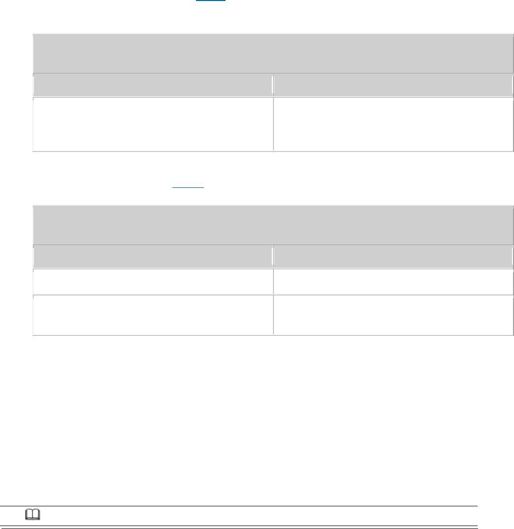
Issue 01 (2017-05-10)
Huawei Proprietary and Confidential
Copyright © Huawei Technologies Co., Ltd.
212
You have logged in to the local maintenance terminal (LMT) by using an account
with the required operation rights.
Procedure
1. In the LMT main window, click Alarm/Event. In the displayed Alarm/Event
window, click the Query Alarm/Event Log tab.
To query the alarms or events generated and cleared within the specified
time, click the Basic tab. Table 1 describes the fields on the Basic tab
page.
Table 1 Description of the fields on the Basic tab page
Field
Description
Max. number of results
Number of records in the query result. A
maximum of 1000 records can be displayed,
and the default number is 64.
To query a type of alarm or event based on the event category and ID,
click the Advanced tab.Table 2 describes the fields on the Advanced tab page.
Table 2 Description of the fields on the Advanced tab page
Field
Description
ID
IDs of the alarms or events to be selected
Serial No
The order of reporting alarms / events for
the query.
2. Set the search criteria as required.
3. Click Query. The query results are displayed in the Result area.
4. To view the detailed information about an alarm or event, double-click the
alarm or event. The Detailed Information dialog box is displayed.
5. In the Detailed Information dialog box, click Solution to query the
description, parameters, attribute, impact on the system, possible causes,
and procedure.
6. Click Close to exit the dialog box.
NOTE:
Issue 01 (2017-05-10)
Huawei Proprietary and Confidential
Copyright © Huawei Technologies Co., Ltd.
213
You can drag the mouse to change the column sequence. After the sequence is changed, the
sequence remains the same when you browse alarms and events again within the cookie validity
period.
Parent topic: Handling Alarms/Events
5.1.1.4.2.4 Saving Alarms/Events
You can save all or part of the alarm or event records displayed on the Browse
Alarm/Event or Query Alarm/Event Log tab page as files in .csv format for future
reference.
Prerequisites
You have logged in to the local maintenance terminal (LMT).
Procedure
1. On the menu bar of the LMT, click the Browse Alarm/Event or Query
Alarm/Event Log tab on the Alarm/Event tab page.
2. Right-click an alarm/event record to be saved and choose Save Selected to
save the record. Choose Save All to save all the alarm/event records.
3. You can also save all the records by clicking the Save All button on the
lower part of the Alarm/Event tab page.
NOTE:
You can click one record and drag the mouse to select multiple alarms/events.
4. Enter the file name, specify the save path, and click Save.
Parent topic: Handling Alarms/Events
5.1.1.4.2.5 Querying Alarm/Event Handling
Suggestions
You can query detailed help information about an alarm or event based on alarm
or event handling suggestions.

Issue 01 (2017-05-10)
Huawei Proprietary and Confidential
Copyright © Huawei Technologies Co., Ltd.
214
Prerequisites
You have logged in to the local maintenance terminal (LMT) by using an account
with the required operation rights.
Context
The detailed help information about an alarm involves the following:
Alarm description
Alarm attribute
Alarm parameters
Impact on the system
System actions
Possible causes
Handling procedure
Procedure
1. Double-click an alarm on the Browse Alarm/Event or Query Alarm or Event Log
tab page.
The Detailed Information dialog box is displayed.
2. In the displayed Detailed Information dialog box, click Solution. The online
help of the alarm or event is displayed.
NOTE:
You can also right-click an alarm or event and choose Solution to display the online help of
the alarm or event.
3. View the definition, parameters, impact on the system, system actions,
possible causes, and handling procedure.
4. Click the close button in the upper right corner of the online help to exit
it.
Parent topic: Handling Alarms/Events
5.1.1.4.2.6 Manually Refreshing Alarms/Events
Issue 01 (2017-05-10)
Huawei Proprietary and Confidential
Copyright © Huawei Technologies Co., Ltd.
215
When browsing or querying alarms or events, you can manually refresh the alarms
or events displayed on the Browse Alarm/Event or Query Alarm/Event Log tab page.
Prerequisites
You have logged in to the local maintenance terminal (LMT) by using an account
with the required operation rights.
Procedure
1. Click Refresh or choose Refresh from the shortcut menu on the Browse
Alarm/Event, or Query Alarm/Event Log tab page.
NOTE:
The alarms or events are displayed on the Browse Alarm/Event tab page in real time.
Therefore, after you refresh the tab page, the cleared alarms are not displayed.
Note:The alarms can be cleared automatically,but the events can not.
The alarms or events are not displayed in real time on the Query Alarm/Event Log tab page.
Therefore, after you manually refresh the tab page, the alarms or events are updated and
displayed based on the original search criteria.
Parent topic: Handling Alarms/Events
5.1.1.4.2.7 Manually Clearing Alarms/Events
If the cause of an alarm or event is identified or the alarm or event can be
ignored, you can manually clear the alarm or event.
Prerequisites
You have logged in to the local maintenance terminal (LMT) by using an account
with the required operation rights.
Context
Manual alarm clearance applies only to automatically detected and manually
cleared (ADMC) alarms but not to automatically detected and automatically
cleared (ADAC) alarms.
Procedure
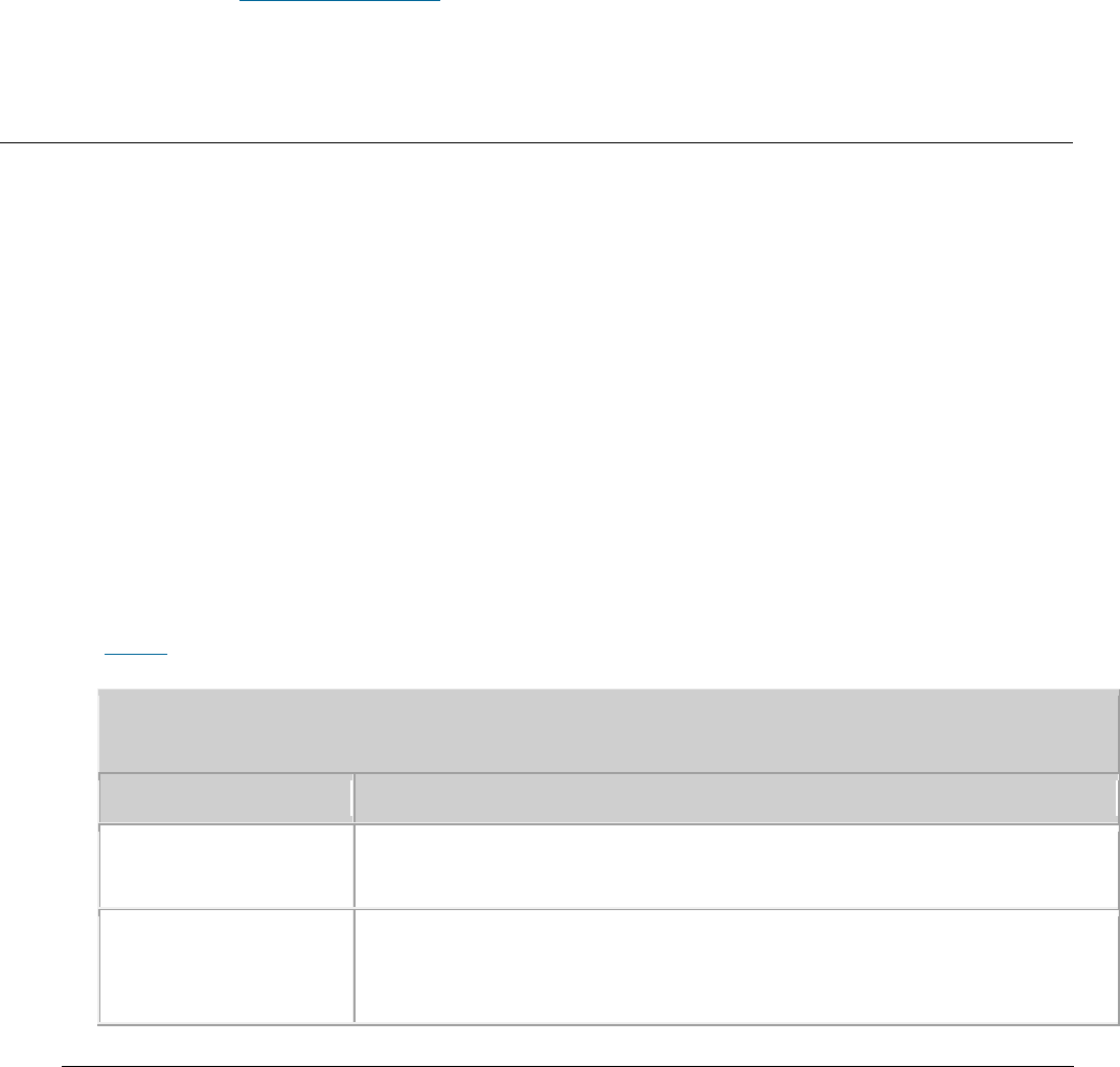
Issue 01 (2017-05-10)
Huawei Proprietary and Confidential
Copyright © Huawei Technologies Co., Ltd.
216
1. Select an alarm or event to be manually cleared on the Browse Alarm/Event or
Query Alarm/Event Log tab page.
2. Right-click the alarm or event and choose Clear from the shortcut menu or
click Clear in the lower right corner.
The Confirm dialog box is displayed.
3. Click Yes. The selected alarm or event is cleared, and its color
automatically changes to the color of a cleared alarm or event.
Parent topic: Handling Alarms/Events
5.1.1.4.2.8 Deleting Cleared Alarms/Events
When browsing active alarms or events or querying alarm or event logs, you can
delete the cleared alarms or events displayed on the Browse Alarm/Eventor Query
Alarm/Event Log tab page.
Prerequisites
You have logged in to the local maintenance terminal (LMT) by using an account
with the required operation rights.
Procedure
1. On the Browse Alarm/Event or Query Alarm/Event Log tab page, click Delete
All ,Delete All Cleared Alarms, or Delete Selected Cleared Alarms to clear
alarms as required.
Table 1describes the functions of these menu items.
Table 1 Menu item functions
Item
Description
Delete All
Deletes all the alarms on the Browse Alarm/Event or Query
Alarm/Event Log tab page.
Delete All Cleared
Alarms
Deletes all the cleared alarms on the Query Alarm/Event Log tab
page or on the Normal Alarm tab page of the Browse Alarm/Event
tab page.
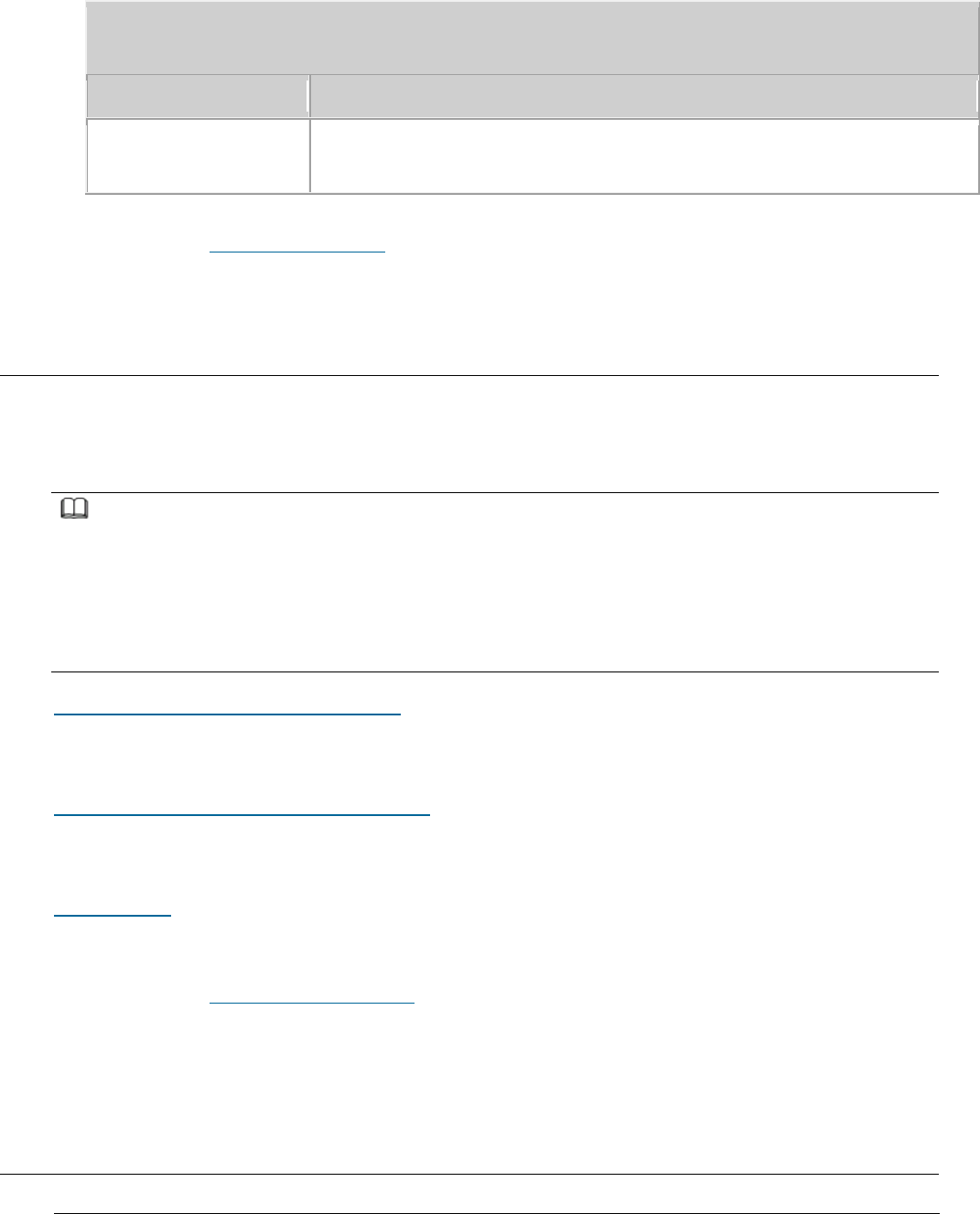
Issue 01 (2017-05-10)
Huawei Proprietary and Confidential
Copyright © Huawei Technologies Co., Ltd.
217
Table 1 Menu item functions
Item
Description
Delete Selected
Cleared Alarms
Deletes all the selected cleared alarms on the Query Alarm/Event
Log tab page.
Parent topic: Handling Alarms/Events
5.1.1.5 Managing Message Tracing
By tracing messages, you can verify data and identify faults. After a message
tracing task is created, the traced messages can be browsed and saved.
NOTE:
Message Tracing is primarily used to monitor the network operating status, commission networks,
and diagnose network faults. Information obtained using this function contains sensitive data
and subscriber-related data. Therefore, enable this function only for legitimate purposes within
a specific scope in compliance with applicable laws and regulations. In addition, before
obtaining and storing communication contents, ensure that measures are taken to securely protect
these contents.
Basic Concepts Related to Message Tracing
This section describes message tracing tasks and the internal process of message
tracing.
General Operations Related to Message Tracing
The general message tracing operations involve browsing, querying, and saving
traced messages and closing a tracing task.
Interface Trace
This section describes how to create interface traces task.
Parent topic: eAN3810A LMT User Guide
5.1.1.5.1 Basic Concepts Related to Message
Tracing

Issue 01 (2017-05-10)
Huawei Proprietary and Confidential
Copyright © Huawei Technologies Co., Ltd.
218
This section describes message tracing tasks and the internal process of message
tracing.
Message Tracing Tasks
Message tracing traces interfaces, signaling links, and UEs. It applies to
routine equipment maintenance and fault location.
Only when the LMT is successfully connected to the NE, the tracing task can be
performed on the LMT.
The message tracing time displayed on the LMT is the NE time but not the LMT
time.
Internal Process of Message Tracing
The internal process of message tracing involves creating a tracing task on the
LMT and reporting results to the LMT.
1. Creating a tracing task on the LMT.
After you create a tracing task on the LMT, the LMT sends a binary command
to the NE to create the task.
The NE forwards the command to a specified tracing management module.
After receiving the command, the tracing management module records the
tracing parameters contained in the command in the filter table and sends
messages to the service processing module.
The service processing module updates the local filter table based on the
messages from the tracing management module.
2. Reporting results to the LMT
After receiving messages from the tracing management module, the service
processing module matches the messages against the parameters in the local
filter table. Then, it reports the messages meeting the filter criteria to
the LMT based on the task IDs contained in the messages.
The LMT analyzes the messages and displays tracing results.
Parent topic: Managing Message Tracing
5.1.1.5.2 General Operations Related to Message
Tracing
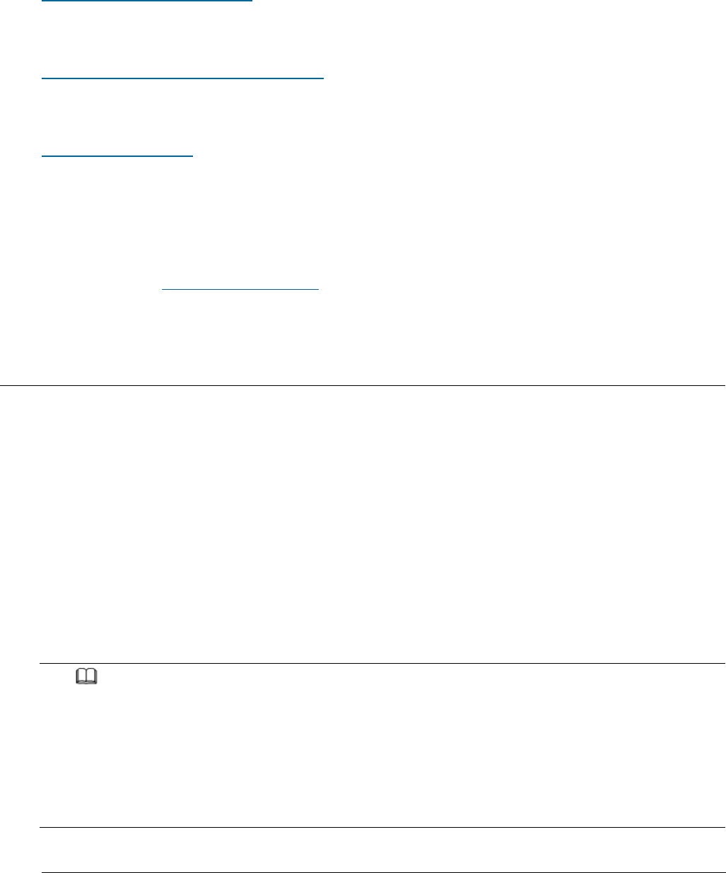
Issue 01 (2017-05-10)
Huawei Proprietary and Confidential
Copyright © Huawei Technologies Co., Ltd.
219
The general message tracing operations involve browsing, querying, and saving
traced messages and closing a tracing task.
Browsing Traced Messages Online
After a message tracing task is created, traced messages can be displayed in
real time. You can browse the traced messages online.
Viewing the Interpretation of Traced Messages
This section describes how to view the details about a traced message in the
message browsing window after a tracing task is created.
Saving Traced Messages
This section describes how to automatically and manually save traced messages.
Traced messages can be automatically saved in files to a local folder after the
task is created. All or some of the traced messages can also be manually saved
when a tracing task is in process. A maximum of 2000 messages can be saved.
Parent topic: Managing Message Tracing
5.1.1.5.2.1 Browsing Traced Messages Online
After a message tracing task is created, traced messages can be displayed in
real time. You can browse the traced messages online.
Prerequisites
Message tracing tasks have been successfully created.
Traced messages are reported.
Procedure
1. Browse traced messages in the message browsing window in real time.
NOTE:
A maximum of 500 messages can be displayed in the message browsing window. Newly traced
messages will replace original ones if the number of displayed messages in the message
browsing window reaches 500.
If the number of the same type of tracing messages that are logged under the same
timestamp is greater than the number of UEs, check whether the RSRP (the value of the
Ant0RsrpRef field in the resolution of the trace message) of a message is greater than
those of other messages by over 20 dB. If so, the tracing result is normal.
2. To view details of a message, double-click it.

Issue 01 (2017-05-10)
Huawei Proprietary and Confidential
Copyright © Huawei Technologies Co., Ltd.
220
The Msg Detail Info dialog box is displayed, showing details of the message.
Parent topic: General Operations Related to Message Tracing
5.1.1.5.2.2 Viewing the Interpretation of Traced
Messages
This section describes how to view the details about a traced message in the
message browsing window after a tracing task is created.
Prerequisites
Message tracing tasks have been successfully created.
Traced messages are reported.
Procedure
1. In the message browsing window, select and double-click a traced message.
2. The Msg Detail Info dialog box is displayed, showing the details about the
message.
Parent topic: General Operations Related to Message Tracing
5.1.1.5.2.3 Saving Traced Messages
This section describes how to automatically and manually save traced messages.
Traced messages can be automatically saved in files to a local folder after the
task is created. All or some of the traced messages can also be manually saved
when a tracing task is in process. A maximum of 2000 messages can be saved.
Prerequisites
The message tracing task has been successfully created.
Traced messages are reported.
Context

Issue 01 (2017-05-10)
Huawei Proprietary and Confidential
Copyright © Huawei Technologies Co., Ltd.
221
The default file name is
Base Station IP address_Trace type_Year-Month-Day-
Hour-Minute-Second_key parameters
.
Traced messages are saved as files in .tmf format.
If you clear the Save File check box when creating a tracing task, the
messages displayed in the message browsing window are not saved.
Procedure
Automatically Saving Traced Messages
1. When a tracing task is created, Save File is selected by default. All
messages displayed in the message browsing window are saved automatically.
NOTE:
The LMT saves every 5000 messages as a file. The messages from the 5001st are saved in
other files whose names are added with a sequence number. For example, the 5001st to
10000th IP messages are saved in a file named
local maintenance IP address _IPTrace_Year-
Month-Day-Hour-Minute-Second_1 by default
.
Manually Saving Traced Messages
1. Right-click in the message browsing window and choose Save All Messages,
or right-click one or more messages to be saved and choose Save Selected
Messages.
NOTE:
If traced messages are manually saved, all messages are displayed in the window.
Currently, a maximum of 2000 messages can be displayed in the window.
A maximum of 2000 messages can be displayed in the window, that is, only the latest
2000 messages are displayed. Therefore, it is good practice to automatically save
traced messages if there are a great number of messages.
To save all traced messages, do not select any message.
To save some of the traced messages, select the messages first. Otherwise, Save
Selected Messages is unavailable after you right-click the selected messages.
2. Enter the file name, specify the save path, and click Save.
Parent topic: General Operations Related to Message Tracing
5.1.1.5.3 Interface Trace
This section describes how to create interface traces task.

Issue 01 (2017-05-10)
Huawei Proprietary and Confidential
Copyright © Huawei Technologies Co., Ltd.
222
MAC Trace
This section describes how to trace Media Access Control (MAC) layer messages to
locate the problems of MAC layer protocol channels. Traced messages can be
automatically or manually saved. You can browse the traced messages online.
IP Layer Protocol Trace
This section describes how to trace IP layer protocol messages to locate the
problems on IP layer protocol channels. Traced messages can be automatically or
manually saved. You can browse the traced messages online.
CMPV2 Trace
This section describes how to trace Certificate Management Protocol Version 2
(CMPV2) messages. Traced messages can be automatically or manually saved. You
can browse the traced messages online.
IKE Trace
This section describes how to trace Internet Key Exchange (IKE) messages to
locate IKE negotiation issues or observe the IKE negotiation process. Traced
messages can be automatically or manually saved. You can browse the traced
messages online.
PNP Trace
This section describes how to trace the site deployment process. Traced messages
can be automatically or manually saved. You can browse the traced messages
online.
Parent topic: Managing Message Tracing
5.1.1.5.3.1 MAC Trace
This section describes how to trace Media Access Control (MAC) layer messages to
locate the problems of MAC layer protocol channels. Traced messages can be
automatically or manually saved. You can browse the traced messages online.
Prerequisite
You have logged in to the LMT using an account with the required operation
rights.
Context
The protocol type, source MAC address, destination MAC address, VLAN tag,
VLAN ID, and VLAN priority are used for identifying messages at the MAC layer.

Issue 01 (2017-05-10)
Huawei Proprietary and Confidential
Copyright © Huawei Technologies Co., Ltd.
223
You can choose one or more items from the protocol type, source MAC address,
destination MAC address, VLAN tag, VLAN ID, and VLAN priority to specify the
scope of messages to be traced. This helps you to trace messages more
specific to a fault.
Currently, packet capture at the MAC layer supports the IP, ARP, RARP,
and SYNCETH protocol types. For details about how to choose the protocol
type, contact Huawei technical support.
The following operations cannot be started simultaneously on one board: the
Mac trace, the IP trace, and the remote loopback that is either applied to
all IP addresses or a specified address.
Procedure
1. In the LMT main window, click the Trace tab.
2. In the navigation tree, choose Trace > Common Services. Double-click MAC
Trace.
The MAC Trace dialog box is displayed.
3. Set related parameters in the MAC Trace dialog box. For details about
parameter descriptions, see Table 1.
Table 1 Parameters for MAC message tracing
Parameter
Description
Frame Flow Upper
Threshold
Specifies the maximum number of packets to be reported per second.
NOTE:
The packets are binary code streams.
Direction
Specifies the direction of MAC messages to be traced. This
parameter can be set to Trace Receiver, Trace Sender, or Trace
Both.
Minimum Frame
Length
Specifies the minimum frame length.
Maximum Frame
Length
Specifies the maximum frame length.
Local MAC Address
Specifies the local MAC address.

Issue 01 (2017-05-10)
Huawei Proprietary and Confidential
Copyright © Huawei Technologies Co., Ltd.
224
Table 1 Parameters for MAC message tracing
Parameter
Description
Peer MAC Address
Specifies the peer MAC address.
VLAN Tag
Specifies the VLAN tag. This parameter can be set to Tagged, All,
or UnTagged.
VALN Priority
Specifies the VLAN priority. This parameter is valid when VLAN
Tag is set to Tagged.
VALN ID
Specifies the VLAN ID. This parameter is valid when VLAN Tag is
set to Tagged.
Frame Type
Specifies the frame type of the MAC messages to be traced. This
parameter can be set to IP, ARP, RARP, SYNCETH, or ALL.
Extend Switch
Specifies whether the filtering switch is turned on. This parameter
can be set to ON, or OFF. The default value is OFF. When
the Frame Type is set to IP, this parameter can be set.
Local IP Address
Specifies the local IP address.
Set this parameter to the source IP address of packets when
Direction is set to Trace Sender, to the destination IP address
when Direction is set to Trace Receiver, and to the source or
destination IP address when Direction is set to Trace Both.
NOTE:
This parameter is valid when Extend Switch is set to ON.
Peer IP Address
Specifies the peer IP address.
Set this parameter to the destination IP address of packets when
Direction is set to Trace Sender, to the source IP address
when Direction is set to Trace Receiver, and to the source or
destination IP address when Direction is set to Trace Both.
NOTE:
This parameter is valid when Extend Switch is set to ON.
DSCP
Specifies the DSCP.
NOTE:
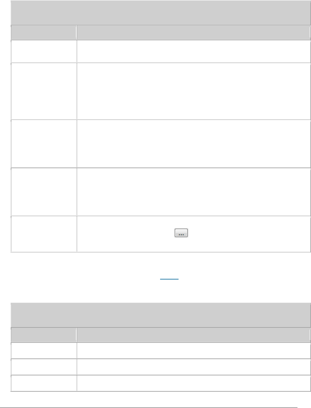
Issue 01 (2017-05-10)
Huawei Proprietary and Confidential
Copyright © Huawei Technologies Co., Ltd.
225
Table 1 Parameters for MAC message tracing
Parameter
Description
This parameter is valid when Extend Switch is set to ON.
Protocol Type
Indicates the protocol type. This parameter can be set to
ALL, ICMP, TCP, UDP, or SCTP.
NOTE:
This parameter is valid when Extend Switch is set to ON.
Local Port
Specifies the local port.
NOTE:
This parameter is valid when Protocol Type is set to TCP, or UDP.
Peer Port
Specifies the peer port.
NOTE:
This parameter is valid when Protocol Type is set to TCP, or UDP.
Save File
If you select the Save File check box, tracing results will be
automatically saved. Click to customize the folder, file name,
and file type.
4. Click Submit.
A message browsing window is displayed. Table 2 describes the message tracing
results.
Table 2 Results of MAC message tracing
Parameter
Description
Message Index
Indicates the message index.
Trace Direction
Indicates the trace direction.
Peer MAC Address
Indicates the destination MAC address.

Issue 01 (2017-05-10)
Huawei Proprietary and Confidential
Copyright © Huawei Technologies Co., Ltd.
226
Table 2 Results of MAC message tracing
Parameter
Description
Local MAC Address
Indicates the source MAC address.
VLAN Priority
Indicates the VLAN priority.
VLAN ID
Indicates the VLAN ID.
Protocol Type
Indicates the protocol type of the traced message. The value can be
ICMP, TCP, UDP, SCTP, or ALL.
Protocol Timestamp
Indicates the message timestamp. Unit: 10 µs.
Content
For details, see G.8264 protocols.
Parent topic: Interface Trace
5.1.1.5.3.2 IP Layer Protocol Trace
This section describes how to trace IP layer protocol messages to locate the
problems on IP layer protocol channels. Traced messages can be automatically or
manually saved. You can browse the traced messages online.
Prerequisite
You have logged in to the LMT using an account with the required operation
rights.
Context
The source IP address, destination IP address, protocol type, IP DSCP, source
port number, and destination port number are used for identifying packets at
the IP layer. The source IP address, destination IP address, and protocol
type are mandatory.
You can specify the protocol type or source/destination port No. to limit the
scope of packet capture.

Issue 01 (2017-05-10)
Huawei Proprietary and Confidential
Copyright © Huawei Technologies Co., Ltd.
227
Either the protocol type or port No. must be specified for locating
transmission problems. Otherwise, the packet capture is less useful for
problem location.
The TCP packets for LMT connection cannot be traced in the IP layer protocol
message tracing task.
The following operations cannot be started simultaneously on one board: the
Mac trace, the IP trace, and the remote loopback that is either applied to
all IP addresses or a specified address.
Procedure
1. In the LMT main window, click Trace to open the Trace dialog box.
2. In the navigation tree, choose Trace > Common Services. Double-click IP
Layer Protocol Trace.
The IP Layer Protocol Trace dialog box is displayed.
3. Set related parameters in the IP Layer Protocol Trace dialog box. For
details about parameter descriptions, see Table 1.
Table 1 Parameters for IP layer protocol message tracing
Parameter
Description
Frame Flow Upper
Threshold
Specifies the maximum number of packets to be reported per second.
Direction
Specifies the transmission direction of packets to be captured.
Receive Report
Length Option
Specifies the length of received packets. This parameter can be set
to Same, Less, or No Report.
Max.Incoming IP
Packets
Specifies the maximum length of a received packet. This parameter
is valid when Receive Report Length Option is set to Same,
or Less.
Transmit Report
Length Option
Specifies the length of transmitted packets. This parameter can be
set to Same, Less, or No Report.
Max.Outgoing IP
Packets
Specifies the maximum length of transmitted packets. This parameter
is valid when Transmit Report Length Option is set to Same,
or Less.
Report Type
Specifies the type of packets to be captured. This parameter can be
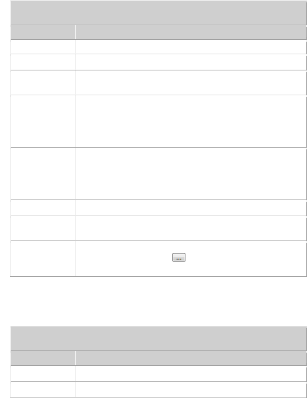
Issue 01 (2017-05-10)
Huawei Proprietary and Confidential
Copyright © Huawei Technologies Co., Ltd.
228
Table 1 Parameters for IP layer protocol message tracing
Parameter
Description
set to Plaintext.
IP Address Type
Specifies the IP address type. This parameter can be set to IPV4.
VRF
Specifies the ID of the virtual routing and forwarding (VRF)
instance.
Local IP Address
Specifies the local IP address.
Set this parameter to the source IP address of packets when
Direction is set to Trace Sender, to the destination IP address
when Direction is set to Trace Receiver, and to the source or
destination IP address when Direction is set to Trace Both.
Peer IP Address
Specifies the peer IP address.
Set this parameter to the destination IP address of packets when
Direction is set to Trace Sender, to the source IP address
when Direction is set to Trace Receiver, and to the source or
destination IP address when Direction is set to Trace Both.
DSCP
Specifies the DSCP.
Protocol Type
Specifies the protocol type of the packets to be captured. This
parameter can be set to ICMP, UDP, SCTP, TCP, or ALL.
Save File
If you select the Save File check box, tracing results will be
automatically saved. Click to customize the folder, file name,
and file type.
4. Click Submit.
A message browsing window is displayed. Table 2 describes the message tracing
results.
Table 2 Results of IP message tracing
Parameter
Description
Message Index
Indicates the internal serial number of a traced message.
Trace Direction
Indicates the direction of a traced message.

Issue 01 (2017-05-10)
Huawei Proprietary and Confidential
Copyright © Huawei Technologies Co., Ltd.
229
Table 2 Results of IP message tracing
Parameter
Description
Header Length
Indicates the IP header length.
Version
Indicates the IP version. The value 4 represents IPv4.
Type Of Service
Indicates the service type of a traced message.
Total Length
Indicates the IP packet length.
Identification
Indicates the tag of a traced message. For details, see the IP
protocol.
Fragment Offset
Field
Indicates the fragment offset of a traced message. For details, see
the IP protocol.
Time To Live
Indicates the life time of a traced message. For details, see the
IP protocol.
Protocol
Indicates the protocol type of a traced message. The value can be
UDP, SCTP, TCP, ICMP, AH, or ESP.
Checksum
Indicates the IP checksum of a traced message. For details, see the
IP protocol.
Source Address
Indicates the source IP address of a traced message.
Dest Address
Indicates the destination IP address of a traced message.
Port Timestamp
Indicates the timestamp (unit: 10 microseconds) of a traced
message.
Packet
Sent(Received)
Sequence Number
A packet has the same sequence number when it is sent or received
in plaintext and ciphertext format. When packets in both
plaintext and ciphertext formats are traced, this parameter
specifies the sequence in which the packets in both plaintext and
ciphertext formats are sent or received.
When only packets in plaintext format are traced, this parameter
specifies the sequence in which the packets in plaintext format
are sent or received.
Packet Type
Indicates the type of the packet that carries a traced message.
Packet Process
Indicates the packet processing result.

Issue 01 (2017-05-10)
Huawei Proprietary and Confidential
Copyright © Huawei Technologies Co., Ltd.
230
Table 2 Results of IP message tracing
Parameter
Description
Result
Source Port
Indicates the source port No. This parameter is valid for UDP, TCP,
and SCTP packets.
Destination Port
Indicates the destination port No. This parameter is valid for UDP,
TCP, and SCTP packets.
UDP Length
Indicates the Length of a UDP packet. This parameter is valid for
UDP packets.
UDP Checksum
Indicates the checksum of a UDP packet. This parameter is valid for
UDP packets. For details, see the UDP protocol.
GTPU TEID
Indicates the TEID of a GTPU packet. This parameter is valid for
GTPU packets. GTPU packets are a type of UDP packets.
SCTP Verification
Flag
Indicates the verification flag for SCTP packets. This parameter is
valid for SCTP packets. For details, see the SCTP protocol.
SCTP Checksum
Indicates the checksum of an SCTP packet. This parameter is valid
for SCTP packets. For details, see the SCTP protocol.
Content
For details, see the IP protocol.
Parent topic: Interface Trace
5.1.1.5.3.3 CMPV2 Trace
This section describes how to trace Certificate Management Protocol Version 2
(CMPV2) messages. Traced messages can be automatically or manually saved. You
can browse the traced messages online.
Prerequisite
You have logged in to the LMT using an account with the required operation
rights.
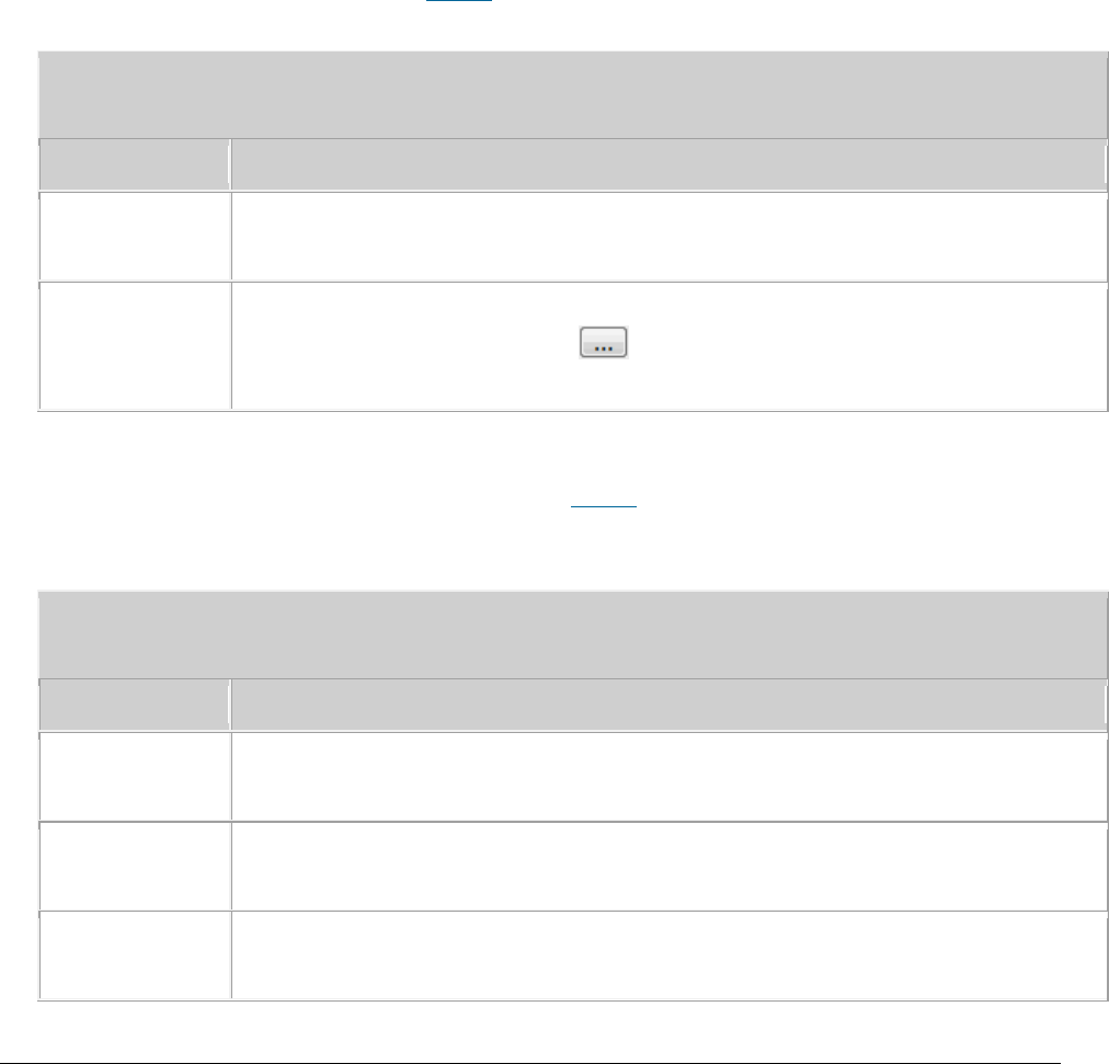
Issue 01 (2017-05-10)
Huawei Proprietary and Confidential
Copyright © Huawei Technologies Co., Ltd.
231
Context
A maximum of one CMPV2 message tracing task can be created at one time.
Procedure
1. In the LMT main window, click the Trace tab.
2. In the navigation tree, choose Trace > Common Services. Double-
click CMPV2 Trace.
The CMPV2 Trace dialog box is displayed.
3. Set related parameters in the CMPV2 Trace dialog box. For details about
parameter descriptions, see Table 1.
Table 1 Parameters for CMPV2 message tracing
Parameter
Description
Direction
Specifies the direction of CMPV2 messages to be traced. This parameter
can be set to Trace Receiver, Trace Sender, or Trace Both.
Save File
If you select the Save File check box, tracing results will be
automatically saved. Click to customize the folder, file name, and
file type.
4. Click Submit.
A message browsing window is displayed. Table 2 describes the message tracing
results.
Table 2 Results of CMPV2 message tracing
Parameter
Description
Trace
Direction
Indicates the direction of traced messages.
Trace Message
Type
Indicates the protocol type of traced messages.
Content
Contains only CMPV2 messages. For details, see RFC protocols and 3GPP
TS 33.310.

Issue 01 (2017-05-10)
Huawei Proprietary and Confidential
Copyright © Huawei Technologies Co., Ltd.
232
Parent topic: Interface Trace
5.1.1.5.3.4 IKE Trace
This section describes how to trace Internet Key Exchange (IKE) messages to
locate IKE negotiation issues or observe the IKE negotiation process. Traced
messages can be automatically or manually saved. You can browse the traced
messages online.
Prerequisite
You have logged in to the LMT using an account with the required operation
rights.
Context
A maximum of one IKE message tracing task can be created at one time.
In an IKE setup or rekey process, IKE negotiation may fail due to algorithm
inconsistency or certificate errors, packets cannot be encrypted because IKE
tunnels are not successfully established. As a result, packets are lost.
Information such as the message type, request, and response about IKEv1 or
IKEv2 message headers can be analyzed.
Procedure
1. In the LMT main window, click the Trace tab.
2. In the navigation tree, choose Trace > Common Services. Double-click IKE
Trace.
The IKE Trace dialog box is displayed.
3. Set related parameters in the IKE Trace dialog box. For details about
parameter descriptions, see Table 1.
Table 1 Parameters for IKE message tracing
Parameter
Description
Direction
Specifies the direction of IKE messages to be traced.
Save File
If you select the Save File check box, tracing results will be

Issue 01 (2017-05-10)
Huawei Proprietary and Confidential
Copyright © Huawei Technologies Co., Ltd.
233
Table 1 Parameters for IKE message tracing
Parameter
Description
automatically saved. Click to customize the folder, file name,
and file type.
4. Click Submit.
A message browsing window is displayed. Table 2 describes the message tracing
results.
Table 2 Results of IKE message tracing
Parameter
Description
Trace Direction
Indicates the direction of the traced message.
Content
For details, see the IKE protocol.
Parent topic: Interface Trace
5.1.1.5.3.5 PNP Trace
This section describes how to trace the site deployment process. Traced messages
can be automatically or manually saved. You can browse the traced messages
online.
Prerequisite
You have logged in to the LMT using an account with the required operation
rights.
Context
A maximum of one PNP message tracing task can be created at one time.
The real-time tracing function for site deployment includes receiving,
sending, checking, and handling of messages. In case of a failure, the
failure cause is displayed.
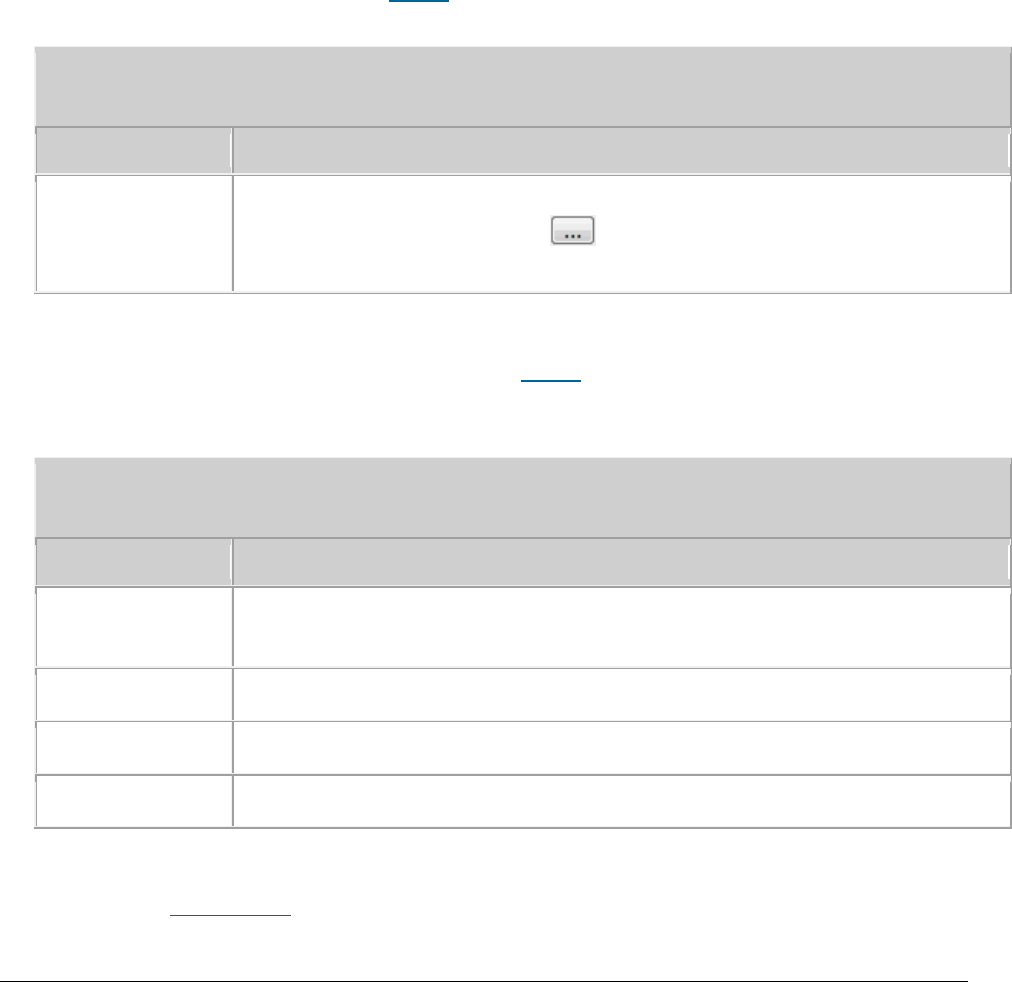
Issue 01 (2017-05-10)
Huawei Proprietary and Confidential
Copyright © Huawei Technologies Co., Ltd.
234
The real-time tracing function can be enabled only by the managing mode of a
multimode base station, only partial deployment information is visible to the
non-managing mode.
Procedure
1. In the LMT main window, click the Trace tab.
2. In the navigation tree, choose Trace > PNP Trace. Double-click PNP Trace.
The PNP Trace dialog box is displayed.
3. Set related parameters in the PNP Trace dialog box. For details about
parameter descriptions, see Table 1.
Table 1 Parameters for PNP message tracing
Parameter
Description
Save File
If you select the Save File check box, tracing results will be
automatically saved. Click to customize the folder, file name,
and file type.
4. Click Submit.
A message browsing window is displayed. Table 2 describes the message tracing
results.
Table 2 Results of PNP message tracing
Parameter
Description
No.
Indicates the sequence of the traced message that received by the
LMT.
Time
Indicates the time of the traced message.
Message Type
Indicates the type of a message, which can be binary or text.
Content
For details, see the site deployment records.
Parent topic: Interface Trace

Issue 01 (2017-05-10)
Huawei Proprietary and Confidential
Copyright © Huawei Technologies Co., Ltd.
235
5.1.1.6 FAQ
This section describes the common issues and solutions during the equipment
commissioning.
Functions of the LMT Becoming Abnormal After an LMT Version Upgrade or Rollback
The displayed version is not the target version. A message indicating that the
MML configuration file fails to be analyzed. The Trace or Monitor tab page can
be normally opened after successful LMT login, but the corresponding functions
are abnormal. For example, the reported messages are not displayed, the reported
messages are not complete or disordered, messages cannot be saved, or only part
of the messages can be saved. The device panel fails to be opened for the first
time after the upgrade.
Slow Responses in the Firefox Browser
When the Firefox browser is used on the local maintenance terminal (LMT), the
LMT response is slow. For example, after you click Monitor, it takes about 30
seconds to maximize the window. In this case, check that the add-on extension
Live Margins is installed.
LMT Colors Cannot Be Displayed
When the LMT uses Internet Explorer, the colors of the LMT main window are not
correctly displayed. For example, the colors indicating the status of boards and
alarms are not displayed, or the background color of the LMT main window is the
same as that of Internet Explorer. In this case, check the color settings of the
browser.
No Response When Clicking the Menu Bar on the LMT
When you use the browse for LMT log in, there is no response or a script error
dialog box is displayed. To be specific, when you click the menu bar or buttons,
or right-click the web page, there is no response or a dialog box is displayed,
indicating a script error, for example, Permission Denied or Access Denied. In
this case, check the proxy settings of the browser.
How to Rectify Errors That Occurr While Saving a File
If the function of saving operation results is configured when you first log in
to the LMT, the system may display an error message during result file saving.
In this case, the file size is zero bytes.
What Do I Do to Avoid the Failure to Log In to the LMT Due to a High Default Internet Explorer Security Level
In Windows Server 2003 or Windows Server 2008, Internet Explorer blocks Web
programs on sites that are not in the trusted site list to improve system
security. As a result, you may fail to log in to the LMT.

Issue 01 (2017-05-10)
Huawei Proprietary and Confidential
Copyright © Huawei Technologies Co., Ltd.
236
What Do I Do to Handle the Slow Redirection When Logging in to the LMT
When the LMT uses Internet Explorer, the redirection is slow when you log in to
the LMT, that is, the explorer remains blank for more than 15 seconds after you
enter the vUSN IP address in the address box of Internet Explorer and before the
explorer displays a security warning. This section describes how to solve the
problem.
What Do I Do to Handle the LMT Interface Disorder
When the LMT uses Internet Explorer 8 or 9, the LMT interface may be displayed
in disorder. In this case, manually set the compatibility views of Internet
Explorer before logging in to the LMT. This section describes the setting method.
What Do I Do to Handle the Unknown Error Occurring on LMT Interface or the MML Command Execution Failure
After a Browser Upgrade
After Internet Explorer 6 is upgraded to Internet Explorer 8 or 9, some cached
files cannot be cleared, an unknown error occurs on the LMT main window, or the
system displays a message indicating an MML configuration file parsing failure
when an MML command is executed. To solve the problem, manually clear the cache
and cookies in Internet Explorer.
What Do I Do to Handle the Interface Display Failure or Error Message Displayed on the LMT
An exception occurs in the login dialog box, a page cannot be properly displayed,
or an error message indicating that an error on the web page may cause the LMT
to malfunction is displayed in Internet Explorer.
A "This user session already exists" Error Message Is Displayed During LMT Login
If a "xxx" message is displayed when you attempt to log in to the LMT, solve the
problem by following the handling procedure described herein.
How to Install OS Patches
If the LMT runs the Microsoft Windows 2003 operating system (OS), the security
patch KB938397 must be installed.
What Do I Do if Tracing Function Cannot Be Used?
Tracing function cannot be used after a successful login to the LMT, and an
error message is displayed.
What Do I Do If There Is No Response or Any Error Message After a Tracing Task Is Created
Some time after a successful login to the LMT, after a tracing task is created,
the task page is not opened. There is no response or any error message. The NE
task list shows that this task has been successfully created. Or right-click in
the message browsing window and choose save messages, the Save dialog box is not
displayed. If you open a new browser and log in to the LMT again, the task
nevertheless can be successfully created. If either of the previous problems
occurs, perform the following operations.

Issue 01 (2017-05-10)
Huawei Proprietary and Confidential
Copyright © Huawei Technologies Co., Ltd.
237
How to Handle the Problem That Only the Error Code Is Displayed in an Error Message After a Tracing Task Is
Created
Messages related to base station errors have been configured. However, the local
maintenance terminal (LMT) displays only the error code rather than the error
message when a base station error occurs. If the previous problem occurs,
perform the following operations:
Any Further Operation Performed When Some LMT Web Pages Fail to Update Causes the Web Pages to Turn
Blank
Some LMT Web pages fail to update when executes man-machine language (MML)
commands, manages alarms and events or traces messages is in use. Any further
operation causes the Web pages to turn blank. If you restart the function, the
Web page returns to normal. To prevent this problem, perform the following
operations to add an environment variable.
How to Handle the LMT Exit After Clicking Trace, Monitor, or Device Maintenance Tab in Window 7
When you have successfully logged in to the LMT, the interface is redirected to
the other interface if you click the MML, Alarms/Event, or Trace tab. A few
seconds after the redirection, the interface is automatically redirected to the
login window of the LMT and a login failure message is prompted.
How to Handle Exceptions in the LMT Due to Insufficient PC Memory
If the memory space for the local maintenance terminal (LMT) PC is insufficient,
exceptions occur when the LMT runs on the PC.
Interfaces for Performing Tracing Task Blinking
Interfaces for performing tracing task blink.
How to Handle Shortcut Key Invalidation
Shortcut keys are defined on the LMT. When logging in to the LMT through a web
page, you may fail to use the corresponding function by pressing a shortcut key.
In this case, the shortcut key becomes invalid. For example, you cannot stop
pinging by pressing Ctrl+Q in the MML Command window. This is because the same
shortcut key is preferentially used by another running program on the PC, which
leads to a shortcut key conflict.
What Do I Do If A Message "Stop running this script?" Is Displayed?
This section describes how to solve the problem that a message "Stop running
this script?" is displayed during script execution on the LMT.
The Internet Explorer Fails to Respond or the Login Window Is Displayed After the LMT Is Running for a While or
Multiple Functions Are Concurrently Enabled on the LMT
The Internet Explorer fails to respond or the login window is displayed after
the LMT is running for a while or multiple functions are concurrently enabled on
the LMT. Solve the problem by using the method described in the procedure part.
A Message checking client environment... Is Displayed on the Login Window and the browser Does Not
Respond

Issue 01 (2017-05-10)
Huawei Proprietary and Confidential
Copyright © Huawei Technologies Co., Ltd.
238
During the login to the WebLMT, a message "checking client environment..." is
displayed on the login window and the browser does not respond and has to be
forcibly closed. In this case, solve the problem by using the method described
in the procedure part.
LMT Login Window Being Stopped by the Browser
The LMT login window is stopped by the browse, and the login stills fails even
though the user selects Allow popups. To solve the problem, perform the
following steps:
The Application Blocked by Security Settings Dialog Box Is Displayed When executes man-machine language
(MML) commands, manages alarms and events, traces messages Is Enabled
After the JRE is installed or upgraded, the Application Blocked by Security
Settings dialog box is displayed when the tab page related to executes man-
machine language (MML) commands, manages alarms and events, traces messages is
open. Click OK, and the The application cannot be run dialog box is displayed,
indicating that the executes man-machine language (MML) commands, manages alarms
and events, traces messages function is unavailable.
Help for Installing and Using the Java Plug-in
The Java plug-in used by LMT modules, including executes man-machine language
(MML) commands, manages alarms and events, traces messages, is the Java runtime
environment(JRE). You need to install the Java plug-in before using these
modules. You can try the following methods to solve problems about installing or
using Java plug-in.
What Do I Do If the Message Your Java version is out of date Is Displayed?
If you are prompted that Your Java version is out of date when logging in to the
WebLMT, follow the instructions provided in this session.
How to Configure Wireless NIC on a Computer
To connect a computer to a local wireless access point device, ensure that the
computer is configured with a WLAN wireless network interface card (NIC). Before
connecting the computer to a local wireless access point device, configure WLAN
wireless NIC by following the instructions below.
Ghosting Occurring on the WebLMT Window That Is Opened Using an IE11 Web Browser
When an IE11 web browser is used for WebLMT access, ghosting occurs on the
WebLMT window, causing overlapping contents. In this case, install the Microsoft
official patch: IE11-Windows6.1-KB2929437-x64.msu.
Parent topic: eAN3810A LMT User Guide

Issue 01 (2017-05-10)
Huawei Proprietary and Confidential
Copyright © Huawei Technologies Co., Ltd.
239
5.1.1.6.1 Functions of the LMT Becoming
Abnormal After an LMT Version Upgrade or
Rollback
The displayed version is not the target version. A message indicating that the
MML configuration file fails to be analyzed. The Trace or Monitor tab page can
be normally opened after successful LMT login, but the corresponding functions
are abnormal. For example, the reported messages are not displayed, the reported
messages are not complete or disordered, messages cannot be saved, or only part
of the messages can be saved. The device panel fails to be opened for the first
time after the upgrade.
To clear the cache and cookies in the browser, perform operations described in
the following table.
Table 1 To clear the cache and cookies in the browser, perform operations
described in the following table.
Browser Type
Handling Procedure
Firefox browser
1. Open the Firefox browser, and choose Tools Clear
Private Data from the menu bar.
2. In the displayed Clear Private Data dialog box,
select Cache, Cookies ,and Offline Website Data and
then click Clear Private Data Now.
Internet Explorer 7
1. Start the IE browser, and choose Tools> Internet
Options Internet Options from the menu bar. The
Internet Options dialog box is displayed.
2. On the General tab page, click Delete. The Delete
Browsing History dialog box is displayed.
3. click Delete File and Delete Cookies,in the
displayed dialog box click OK.
4. In the Delete Browsing History dialog box clickOK
and close the Internet Optionsdialog box.
Internet Explorer 8 or 9
1. Start the IE browser, and choose Tools> Internet
Options Internet Options from the menu bar. The
Internet Options dialog box is displayed.
2. On the General tab page, click Delete. The Delete

Issue 01 (2017-05-10)
Huawei Proprietary and Confidential
Copyright © Huawei Technologies Co., Ltd.
240
Table 1 To clear the cache and cookies in the browser, perform operations
described in the following table.
Browser Type
Handling Procedure
Browsing History dialog box is displayed.
3. Clear the Preserve Favorites website data check box
and select Cookies and Temporary Internet files .
Then click Delete and close the Internet Options
dialog box.
Internet Explorer 10
1. Start the IE browser, and choose Tools> Internet
Options Internet Options from the menu bar. The
Internet Options dialog box is displayed.
2. On the General tab page, click Delete. The Delete
Browsing History dialog box is displayed.
3. Clear the Preserve Favorites website data check box
and select Cookies and website data and Temporary
Internet files and website files. Then click Delete
and close the Internet Options dialog box.
Parent topic: FAQ
5.1.1.6.2 Slow Responses in the Firefox Browser
When the Firefox browser is used on the local maintenance terminal (LMT), the
LMT response is slow. For example, after you click Monitor, it takes about 30
seconds to maximize the window. In this case, check that the add-on extension
Live Margins is installed.
Procedure
1. Open the Firefox browser, and choose Tools > Add-ons, from the menu bar. The
Add-ons window is displayed.
2. On the Extensions tab page, select Live Margins, , and click Disable A
message is displayed, indicating that the changes will take effect after the
Firefox browser is restarted.
3. Click Restart Firefox to make the changes take effect.

Issue 01 (2017-05-10)
Huawei Proprietary and Confidential
Copyright © Huawei Technologies Co., Ltd.
241
Parent topic: FAQ
5.1.1.6.3 LMT Colors Cannot Be Displayed
When the LMT uses Internet Explorer, the colors of the LMT main window are not
correctly displayed. For example, the colors indicating the status of boards and
alarms are not displayed, or the background color of the LMT main window is the
same as that of Internet Explorer. In this case, check the color settings of the
browser.
Procedure
1. Open Internet Explorer, and choose Tools > Internet Options from the menu
bar. The Internet Options dialog box is displayed.
2. On the General tab page, click Accessibility, The Accessibility dialog box
is displayed.
3. In the Formatting area, select Ignore colors specified on Web pages ,and
click OK.
4. In the Internet Options dialog box, click OK to exit the dialog box.
Parent topic: FAQ
5.1.1.6.4 No Response When Clicking the Menu
Bar on the LMT
When you use the browse for LMT log in, there is no response or a script error
dialog box is displayed. To be specific, when you click the menu bar or buttons,
or right-click the web page, there is no response or a dialog box is displayed,
indicating a script error, for example, Permission Denied or Access Denied. In
this case, check the proxy settings of the browser.
Context
Do not change the settings of Internet Explorer when the LMT is in use. Set the
proxy server before you log in to the LMT.

Issue 01 (2017-05-10)
Huawei Proprietary and Confidential
Copyright © Huawei Technologies Co., Ltd.
242
Procedure
1. Open Internet Explorer, and choose Tools > Internet Options from the menu
bar. The Internet Options dialog box is displayed.
2. On the Connections tab page, click LAN Settings. The LAN Settings dialog box
is displayed.
3. In the Proxy server area, select Use a proxy server for your LAN (These
settings will not apply to dial-up or VPN connections). Enter the IP address
and port number of the proxy server in the corresponding boxes, and then
click Advanced. . The Proxy settings dialog box is displayed.
4. In the Exceptions area, enter the IP address of the vUSN for local
maintenance in the text box. The default IP address is 192.168.0.49. Then,
click OK and close the Internet Options dialog box.
Parent topic: FAQ
5.1.1.6.5 How to Rectify Errors That Occurr
While Saving a File
If the function of saving operation results is configured when you first log in
to the LMT, the system may display an error message during result file saving.
In this case, the file size is zero bytes.
Procedure
1. Choose Start > Control Panel. In Control Panel, click Java. The JAVA Control
Panel is displayed.
NOTE:
If you do not see the Java item in Control Panel, switch to another view.
2. In Java Control Panel, click the Advanced tab. On the displayed tab page,
choose Java Plug-in > Enable the next-generation Java Plug-in (requires
browser restart) in the Settings navigation tree, and then click OK.
3. Restart the LMT.
Parent topic: FAQ

Issue 01 (2017-05-10)
Huawei Proprietary and Confidential
Copyright © Huawei Technologies Co., Ltd.
243
5.1.1.6.6 What Do I Do to Avoid the Failure to
Log In to the LMT Due to a High Default Internet
Explorer Security Level
In Windows Server 2003 or Windows Server 2008, Internet Explorer blocks Web
programs on sites that are not in the trusted site list to improve system
security. As a result, you may fail to log in to the LMT.
Context
According to acceptable Internet Explorer security levels, there are the
following two solutions:
If lowering Internet Explorer security level on the Windows server is
unacceptable, you can add the LMT site to the trusted site list of Internet
Explorer using a configuration startup script. The system automatically loads
the script and configures Internet Explorer after a user logs in.
If lowering Internet Explorer security level on the Windows server is
acceptable, you can remove Internet Explorer Enhanced Security Configuration,
a Windows component.
Procedure
To set a configuration startup script, perform the following steps:
1. Create a configuration startup script.
Enter the following script contents in a notepad and save it as an IE-
unset.bat file.
@echo off
setlocal ENABLEDELAYEDEXPANSION
set uu="HKEY_CURRENT_USER\Software\Microsoft\Windows\CurrentVersion\Internet Settings"
reg add %uu% /v EnableHttp1_1 /t REG_DWORD /d "1" /f >nul
reg add %uu% /v ProxyHttp1.1 /t REG_DWORD /d "1" /f >nul
setlocal ENABLEDELAYEDEXPANSION
set uu="HKEY_CURRENT_USER\Software\Microsoft\Windows\CurrentVersion\Internet
Settings\ZoneMap\EscRanges\Trust"
reg add %uu% /v :Range /t REG_SZ /d "10.141.149.193" /f >nul
reg add %uu% /v http /t REG_DWORD /d "2" /f >nul
reg add %uu% /v https /t REG_DWORD /d "2" /f >nul
NOTE:

Issue 01 (2017-05-10)
Huawei Proprietary and Confidential
Copyright © Huawei Technologies Co., Ltd.
244
The IE-unset.bat script file enables the system to automatically add a site to the
trusted site list of Internet Explorer.
You can modify the file when required, for example, change 10.141.149.193 in reg
add %uu% /v :Range REG_SZ /d "10.141.149.193" /f >nul to the IP address of the network
element to be visited. The Trust field in
The Trust field in
HKEY_CURRENT_USER\Software\Microsoft\Windows\CurrentVersion\Internet
Settings\ZoneMap\EscRanges\Trust can be named as required.
2. Load the startup script.
If the LMT runs on a Windows server, perform the following steps to set
the script:
a. Log in to the Windows server with an administrator account, and
choose Start Run.
b. Enter gpedit.msc in the displayed dialog box, and click OK. The
Group Policy Object Editor dialog box is displayed.
c. In the displayed dialog box, choose User Configuration Windows
Settings Scripts(Logon/Logoff), and double-click Logon.
d. Click Show Files and copy the created script to the displayed folder.
Then, close the dialog box displaying the folder.
e. Click Add. The Add a Script dialog box is displayed.
f. Click Browse to select the created script and click OK.
g. Click Apply and verify that the script is loaded successfully
If the LMT runs on a Citrix Farm network, perform the following steps to set
the script:
1. Log in to the primary or secondary Citrix domain control server with an
administrator account, and choose StartProgramsAdministrative ToolsActive
Directory Users and Computer. Select an organization unit such as OSS and
right-click Properties. Click the Group Policy tab in the displayed dialog
box, and click Newon the displayed tab page to create a group policy
object.
NOTE:
You can rename the group policy object as required.
2. Select the created group policy object and click Edit. In the displayed
dialog box, choose User ConfigurationWindows SettingsScripts(Logon/Logoff),
and double-click Logon. The Logon Propertiesdialog box is displayed.

Issue 01 (2017-05-10)
Huawei Proprietary and Confidential
Copyright © Huawei Technologies Co., Ltd.
245
3. Click Show Filesand copy the created script to the displayed folder. Then,
close the dialog box displaying the folder.
4. Click Add. The Add a Scriptdialog box is displayed.
5. Click Browseto select the created script and click OK.
6. ClickApply and verify that the script is loaded successfully.
To remove Internet Explorer Enhanced Security Configuration, perform the
following steps:
1. Choose StartControl Panel Add or Remove Programs. In the displayed dialog
box, select Internet Explorer Enhanced Security Configuration.
2. Click Details. In the displayed dialog box, clear For administrator groups
and For all other user groups.
3. Click OKand then Nextto remove Internet Explorer Enhanced Security
Configuration. After the removal is completed, click Finish.
4. Restart Internet Explorer to make the settings take effect.
Parent topic: FAQ
5.1.1.6.7 What Do I Do to Handle the Slow
Redirection When Logging in to the LMT
When the LMT uses Internet Explorer, the redirection is slow when you log in to
the LMT, that is, the explorer remains blank for more than 15 seconds after you
enter the vUSN IP address in the address box of Internet Explorer and before the
explorer displays a security warning. This section describes how to solve the
problem.
Prerequisites
The LMT directly communicates with the eAN3810A.
You log in to the LMT in HTTPS mode.
The operating system is Microsoft Windows 2003.
Context

Issue 01 (2017-05-10)
Huawei Proprietary and Confidential
Copyright © Huawei Technologies Co., Ltd.
246
In HTTPS mode, the interface will be redirected to HTTPS after you enter the IP
address in the address box of Internet Explorer. After you log in to the LMT in
HTTPS mode, Windows visits the Microsoft website and updates the trusted root
certification list until the update succeeds or expires. In this period, the
certification authentication in HPPTS mode is slow. Generally, when you use the
LMT to visit the eSE, you are on the Intranet but not the Internet. You can
accelerate the visit to the LMT by disabling this function.
Procedure
1. Click Start Control Panel. The Control Panel is displayed.
2. In Control Panel, click Add or Remove Programs. The Add or Remove Programs
window is displayed.
3. In the Add or Remove Programs window, click Add/Remove Windows Components.
The Windows Components Wizard window is displayed.
4. In the Components area of the Windows Components Wizard window, clear the
Update Root Certificates check box.
5. Click Next. The system automatically performs the configuration.
6. After the configuration is complete, click Finish.
Parent topic: FAQ
5.1.1.6.8 What Do I Do to Handle the LMT
Interface Disorder
When the LMT uses Internet Explorer 8 or 9, the LMT interface may be displayed
in disorder. In this case, manually set the compatibility views of Internet
Explorer before logging in to the LMT. This section describes the setting method.
Prerequisites
Internet Explorer 8 or 9 is used.
The LMT interface is displayed in disorder.
Procedure
1. Open Internet Explorer. Choose Tools Compatibility View Settings. The
Compatibility View Settings dialog box is displayed.

Issue 01 (2017-05-10)
Huawei Proprietary and Confidential
Copyright © Huawei Technologies Co., Ltd.
247
2. In the Add this website text box, enter the IP address of the network
element (NE), for example, 10.147.212.161. Click Add. Select the Display all
websites in compatibility view check box and click Close.
3. The LMT interface is displayed in order after you log in to the LMT again.
Parent topic: FAQ
5.1.1.6.9 What Do I Do to Handle the Unknown
Error Occurring on LMT Interface or the MML
Command Execution Failure After a Browser
Upgrade
After Internet Explorer 6 is upgraded to Internet Explorer 8 or 9, some cached
files cannot be cleared, an unknown error occurs on the LMT main window, or the
system displays a message indicating an MML configuration file parsing failure
when an MML command is executed. To solve the problem, manually clear the cache
and cookies in Internet Explorer.
Procedure
1. Open Internet Explorer 8 or 9, and choose Tools Internet Options from the
menu bar. The Internet Options dialog box is displayed.
2. On the General tab page, click Delete in the Browsing history area. The
Delete Browsing History dialog box is displayed.
3. Clear the Preserve Favorites website data check box, select the Cookie and
Temporary Internet files check boxes, and click Delete.
4. Close the Delete Browsing History dialog box.
5. On the General tab page, click Settings in the Browsing historyarea. The
Temporary Internet Files and History Settings dialog box is displayed.
6. Click View objects and delete all displayed files.
7. Close the displayed window and the Internet Options dialog box.
Parent topic: FAQ

Issue 01 (2017-05-10)
Huawei Proprietary and Confidential
Copyright © Huawei Technologies Co., Ltd.
248
5.1.1.6.10 What Do I Do to Handle the Interface
Display Failure or Error Message Displayed on
the LMT
An exception occurs in the login dialog box, a page cannot be properly displayed,
or an error message indicating that an error on the web page may cause the LMT
to malfunction is displayed in Internet Explorer.
Context
If Internet Explorer is upgraded or the buffer of Internet Explorer is
insufficient, Internet Explorer cannot obtain new files from the eAN3810A after
the eAN3810A is upgraded. The Internet Explorer obtains files about the eAN3810A
in the original version from the buffer, causing information inconsistency.
Procedure
Internet Explorer
1. Open Internet Explorer, and choose Tools Internet Options from the menu
bar. The Internet Options dialog box is displayed.
2. On the General tab page, click Delete in the Browsing history area. The
Delete Browsing History dialog box is displayed.
3. Clear the Preserve Favorites website data check box, select the Cookie and
Temporary Internet files check boxes, and click Delete.
4. Close the Delete Browsing History dialog box.
5. On the General tab page, click Settings in the Browsing history area. The
Temporary Internet Files and History Settings dialog box is displayed.
6. Click View objects and delete all displayed files.
7. Close the displayed window and the Internet Options dialog box.
Firefox
1. Open the Firefox browser, and choose Tools Clear Private Data from the
menu bar.
2. In the displayed Clear Private Data dialog box, select the Cache, Cookies,
and Offline Website Data check boxes, and click Clear Private Data Now.
Parent topic: FAQ

Issue 01 (2017-05-10)
Huawei Proprietary and Confidential
Copyright © Huawei Technologies Co., Ltd.
249
5.1.1.6.11 A "This user session already exists"
Error Message Is Displayed During LMT Login
If a "xxx" message is displayed when you attempt to log in to the LMT, solve the
problem by following the handling procedure described herein.
Context
To improve the system security, the browser on the LMT PC uses cookies to save
session information about the users who have successfully logged in to the LMT.
The mechanism of using cookies to save session information causes the following
problems:
When a user attempts to open another LMT for an NE after successfully logging
in to an LMT for the same NE, a message indicating that the user session
exists is displayed. This problem occurs because Internet Explorer 8 or 9 and
Firefox browsers use the session sharing mechanism. All browser windows
opened by the same user share a session. When the LMT for an NE is opened
again, the browser regards the login as repeated login with the same user
session. In Internet Explorer 6 or 7, each browser window uses an independent
session, and the preceding problem does not occur.
The message indicating that the user session exists is displayed although the
user did not attempt to perform the operation described in the preceding
problem. This problem occurs when the LMT is exited unexpectedly. After the
unexpected exit, the cookie saving the login session information is still
valid. As a result, when the user logs in to the LMT again, the browser
regards the login as repeated login with the same user session. The LMT may
be unexpectedly exited if the browser becomes faulty whereas the LMT is being
used or when the pop-up blocker of the browser is enabled.
Procedure
To address the first problem:
1. In the menu bar of Internet Explorer, choose FileNew Session to open a new
Internet Explorer window. Use this newly opened window to log in to the
LMT.
NOTE:
This method applies only to Internet Explorer 8 or 9. If the Firefox browser is used,
only one LMT can be opened for an NE.

Issue 01 (2017-05-10)
Huawei Proprietary and Confidential
Copyright © Huawei Technologies Co., Ltd.
250
To address the second problem:
1. Close all browser windows so that all session information becomes invalid.
2. If the pop-up blocker is enabled in the browser, disable it.
3. Restart the browser, and log in to the LMT again.
Parent topic: FAQ
5.1.1.6.12 How to Install OS Patches
If the LMT runs the Microsoft Windows 2003 operating system (OS), the security
patch KB938397 must be installed.
Context
Patch KB938397 rectifies the problem that the Windows operating system does not
support SHA256.
Procedure
1. Choose Start > Control Panel. The Control Panel is displayed. Double-click
Add or Remove Programs in the displayed window. The Add or Remove Programs
dialog box is displayed.
2. In the displayed Add or Remove Programs dialog box, select Show updates.
Check whether patch KB938397 is present in the list of Currently installed
programs.
If the patch is present in the list, contact Huawei technical support.
If the patch is not present in the list, go to 3.
3. Download the security patch.
Parent topic: FAQ
5.1.1.6.13 What Do I Do if Tracing Function
Cannot Be Used?
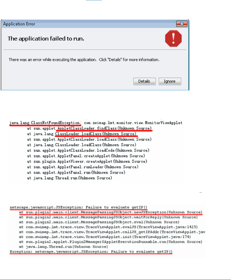
Issue 01 (2017-05-10)
Huawei Proprietary and Confidential
Copyright © Huawei Technologies Co., Ltd.
251
Tracing function cannot be used after a successful login to the LMT, and an
error message is displayed.
Context
The error message is shown in Figure 1. After clicking Details, detailed error
information is displayed. You need to correct the error based on the error type.
Figure 1 The error message dialog box
If the java.lang.ClassNotFoundException error is displayed, perform steps 1
and 2.
Figure 2 java.lang.ClassNotFoundException error
If the netscape.javascript.JSException error is displayed, perform 3.
Figure 3 netscape.javascript.JSException error
If this problem occurs in Citrix Farm networking, you need to perform related
steps on the Citrix Farm server rather than on the local PC. If you have no
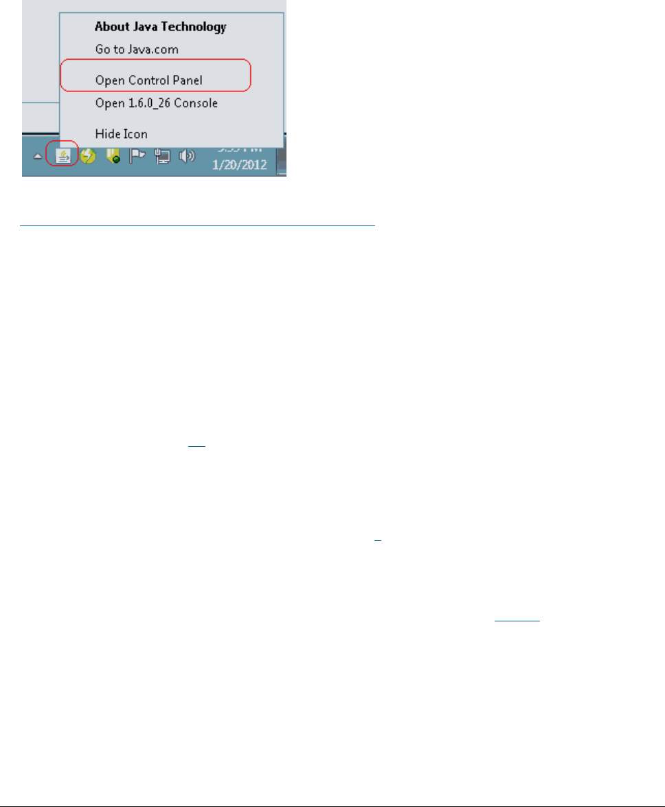
Issue 01 (2017-05-10)
Huawei Proprietary and Confidential
Copyright © Huawei Technologies Co., Ltd.
252
permission to log in to the Citrix Farm server, you cannot directly access
Windows Control Panel on the Citrix Farm server. To access it, right-click
the Java icon on Windows system tray on the local PC and choose Open Control
Panel from the short-cut menu. The following figure shows the window:
Figure 4 Opening control panel
This problem is caused by a Java defect. For details about this defect, visit
http://bugs.sun.com/bugdatabase/view_bug.do?bug_id=6967414.
Procedure
1. Enable the next-generation Java plug-in again.
a. Open Control Panel in the Windows operating system and double-click Java.
The Java Control Panel dialog box is displayed. In the Java Control Panel
dialog box, click the Advanced tab, clear Enable the next-generation Java
Plug-in (requires browser restart) under Java Plug-in and click OK.
b. Select Enable the next-generation Java Plug-in (requires browser restart)
by referring to 1.a and click OK.
c. Restart the browser to enable the new setting to take effect.
2. Delete temporary Java files.
If this problem persists after performing 1, delete temporary Java files.
a. Open Control Panel in the Windows operating system and double-click Java.
The Java Control Panel dialog box is displayed.In the displayed Java
Control Panel dialog box, click Setting, as shown in Figure 5.
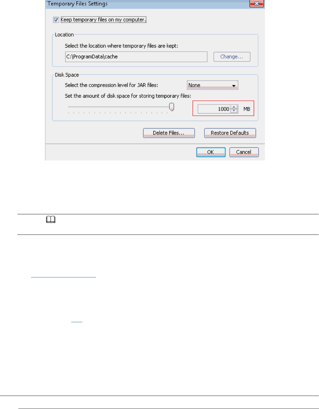
Issue 01 (2017-05-10)
Huawei Proprietary and Confidential
Copyright © Huawei Technologies Co., Ltd.
253
Figure 5 Checking the amount of disk space set for storing temporary files
b. Check the amount of disk space used for storing temporary Java files in
the directory where temporary Java files are saved. If this amount is
greater than the preset one, delete folders in this directory manually or
by clicking Delete Files shown in the figure above.
NOTE:
Before deleting folders in this directory, close all running LMT clients.
c. Log in to the LMT again to check whether this problem is solved.
3. Install Windows operating system patch KB960714, for more details please see
How to Install OS Patches.
If this problem cannot be solved by performing the above steps, uninstall
and reinstall Java.
Parent topic: FAQ
5.1.1.6.14 What Do I Do If There Is No Response
or Any Error Message After a Tracing Task Is
Created

Issue 01 (2017-05-10)
Huawei Proprietary and Confidential
Copyright © Huawei Technologies Co., Ltd.
254
Some time after a successful login to the LMT, after a tracing task is created,
the task page is not opened. There is no response or any error message. The NE
task list shows that this task has been successfully created. Or right-click in
the message browsing window and choose save messages, the Save dialog box is not
displayed. If you open a new browser and log in to the LMT again, the task
nevertheless can be successfully created. If either of the previous problems
occurs, perform the following operations.
Procedure
1. Open Control Panel in the Windows operating system and double-click Java.
The Java Control Panel dialog box is displayed.
2. In the displayed Java Control Panel dialog box, click the Advanced tab.
If the Java plug-in of version 1.6 is installed, choose Security >
SecurityMixed code (sandboxed vs. trusted) security verification, and
select Disable verification (not recommended).
If the Java plug-in of version 1.7 or 1.8 is installed, choose
SecurityMixed code (sandboxed vs. trusted) security verification, and
select Disable verification (not recommended).
3. Close all browsers and log in to the LMT again.
Parent topic: FAQ
5.1.1.6.15 How to Handle the Problem That Only
the Error Code Is Displayed in an Error Message
After a Tracing Task Is Created
Messages related to base station errors have been configured. However, the local
maintenance terminal (LMT) displays only the error code rather than the error
message when a base station error occurs. If the previous problem occurs,
perform the following operations:
Procedure
1. Open Control Panel in the Windows operating system and double-click Java.
The Java Control Panel dialog box is displayed.

Issue 01 (2017-05-10)
Huawei Proprietary and Confidential
Copyright © Huawei Technologies Co., Ltd.
255
2. In the displayed Java Control Panel dialog box, click the Advanced tab,
choose SecurityMixed code (sandboxed vs. trusted) security verification ,
and select Disable verification (not recommended).
3. Close all browsers and log in to the LMT again.
Parent topic: FAQ
5.1.1.6.16 Any Further Operation Performed
When Some LMT Web Pages Fail to Update
Causes the Web Pages to Turn Blank
Some LMT Web pages fail to update when executes man-machine language (MML)
commands, manages alarms and events or traces messages is in use. Any further
operation causes the Web pages to turn blank. If you restart the function, the
Web page returns to normal. To prevent this problem, perform the following
operations to add an environment variable.
Procedure
1. On the LMT PC, select My Computer and right-click Properties from the
shortcut menu. The System Properties dialog box is displayed.
2. In the System Properties dialog box, click the Advanced tab and click
Environment Variables. The Environment Variables dialog box is displayed.
3. In the Environment Variables dialog box, click New. The New User Variable
dialog box is displayed. In the New User Variable dialog box, set Variable
name to JPI_PLUGIN2_NO_HEARTBEAT and Variable value to 1. Then click OK.
4. In the Environment Variables dialog box, click OK.
5. In the System Properties dialog box, click OK to finish adding the
environment variable.
Parent topic: FAQ

Issue 01 (2017-05-10)
Huawei Proprietary and Confidential
Copyright © Huawei Technologies Co., Ltd.
256
5.1.1.6.17 How to Handle the LMT Exit After
Clicking Trace, Monitor, or Device Maintenance
Tab in Window 7
When you have successfully logged in to the LMT, the interface is redirected to
the other interface if you click the MML, Alarms/Event, or Trace tab. A few
seconds after the redirection, the interface is automatically redirected to the
login window of the LMT and a login failure message is prompted.
Context
The IERationalEnabler Class plug-in is installed in Internet Explorer when test
tools, such as IBM Rational Functional Tester (RTF), are installed in the PC.
The problem can be resolved by disabling the plug-in.
Procedure
1. Choose ToolsInternet from the menu bar of Internet Explorer.
The Internet dialog box is displayed.
2. Click Manage Add-ons on the Programs tab page.
The Manage Add-ons dialog box is displayed.
3. Choose Toolbras and Extensions in the Add-Ins navigation tree. Click
IERationalEnabler Class on the right of the dialog box and disable the plug-
in.
4. Close all the opened Internet Explorer and log in to the LMT again.
Parent topic: FAQ
5.1.1.6.18 How to Handle Exceptions in the LMT
Due to Insufficient PC Memory
If the memory space for the local maintenance terminal (LMT) PC is insufficient,
exceptions occur when the LMT runs on the PC.
Context

Issue 01 (2017-05-10)
Huawei Proprietary and Confidential
Copyright © Huawei Technologies Co., Ltd.
257
When a PC has been running for a long time or multiple programs occupying huge
memory space are running on the PC, memory usage of the PC almost reaches 100%.
In this case, if the LMT starts, the PC cannot allocate sufficient memory space
to the LMT, and exceptions occur, such as slower user interface (UI) response
and unavailability of tracing functions.
Mappings between the PC memory and the number of LMT clients that can
simultaneously start on the PC are as follows:
On a PC of 4 GHz memory, 32 LMT clients can simultaneously start.
On a PC of 2 GHz memory, 16 LMT clients can simultaneously start.
On a PC of 1 GHz memory, eight LMT clients can simultaneously start.
On a PC of 512 MHz memory, four LMT clients can simultaneously start.
NOTE:
The preceding mappings are obtained when no other software is running on the PC and only basic
functions, such as MML, alarm, and device panel, are used on the LMT. When other functions are
running on an LMT such as tracing, the LMT will consume over 50 MHz memory on the PC. Therefore,
fewer LMT clients can simultaneously start on the PC.
Procedure
1. Log off or restart the PC, or stop programs occupying huge memory space.
2. Log in to the LMT again.
Parent topic: FAQ
5.1.1.6.19 Interfaces for Performing Tracing Task
Blinking
Interfaces for performing tracing task blink.
Context
Java Applet in the IE browser is incompatible with HTML elements when they are
stacked together. As a result, interfaces (stacked in the Java Applet) for
performing tracing task blink. This problem does not affect the function but
deteriorates user experience.
Procedure

Issue 01 (2017-05-10)
Huawei Proprietary and Confidential
Copyright © Huawei Technologies Co., Ltd.
258
To avoid this problem, use the following methods:
1. This problem occurs only on the IE browser. Use the Firefox browser to
avoid this problem.
2. This problem occurs only on Java later than the version of 1.6.21. Visit
www.oracle.com and download Java SE Runtime Environment 6u21 or an earlier
version to avoid this problem.
Parent topic: FAQ
5.1.1.6.20 How to Handle Shortcut Key
Invalidation
Shortcut keys are defined on the LMT. When logging in to the LMT through a web
page, you may fail to use the corresponding function by pressing a shortcut key.
In this case, the shortcut key becomes invalid. For example, you cannot stop
pinging by pressing Ctrl+Q in the MML Command window. This is because the same
shortcut key is preferentially used by another running program on the PC, which
leads to a shortcut key conflict.
Procedure
1. Check all running programs on the PC. Find the program using the same
shortcut key settings as the LMT.
2. Modify the program shortcut key settings which are the same as those on the
LMT or stop the program when you use the LMT.
Parent topic: FAQ
5.1.1.6.21 What Do I Do If A Message "Stop
running this script?" Is Displayed?
This section describes how to solve the problem that a message "Stop running
this script?" is displayed during script execution on the LMT.
Context

Issue 01 (2017-05-10)
Huawei Proprietary and Confidential
Copyright © Huawei Technologies Co., Ltd.
259
When it takes a long time to execute certain scripts, you are prompted with the
message "Stop running this script?", indicating whether to continue the script
execution.
To solve this problem, download the file at
http://download.microsoft.com/download/5/9/5/595D11B8-A0FD-4EA0-BF0D-F113258FC28A/MicrosoftFixit50403.msi.
Procedure
1. Install the downloaded file.
2. Restart the computer, and then log in to the LMT to check whether this
problem has been solved.
Parent topic: FAQ
5.1.1.6.22 The Internet Explorer Fails to Respond
or the Login Window Is Displayed After the LMT
Is Running for a While or Multiple Functions Are
Concurrently Enabled on the LMT
The Internet Explorer fails to respond or the login window is displayed after
the LMT is running for a while or multiple functions are concurrently enabled on
the LMT. Solve the problem by using the method described in the procedure part.
Context
If the LMT installed with multiple network adapters, the problem mentioned above
may occur. For Internet Explorer's failing to respond, the check result of the
task manager shows that the virtual memory occupied by the Internet Explorer
process exceeds 1 GHz. For the displayed login window, the check result of the
task manager shows the Internet Explorer progress for the LMT window has been
abnormally closed. In this case, the automatic recovery mechanism of the
Internet Explorer displays the last access webpage when you open the Internet
Explorer again.
Procedure
Log in to the LMT through a Firefox browser. The Firefox browser versions
30.X or later are supported.

Issue 01 (2017-05-10)
Huawei Proprietary and Confidential
Copyright © Huawei Technologies Co., Ltd.
260
If the LMT is running Windows 7, log in to the LMT through Internet Explorer
8.0 or later.
Parent topic: FAQ
5.1.1.6.23 A Message checking client
environment... Is Displayed on the Login
Window and the browser Does Not Respond
During the login to the WebLMT, a message "checking client environment..." is
displayed on the login window and the browser does not respond and has to be
forcibly closed. In this case, solve the problem by using the method described
in the procedure part.
Context
After the WebLMT is started, the software environment of the client is checked,
including the versions and basic settings of Java applications, Adobe Flash
Player, and browser. If the browser does not respond, faults occur on the
software.
Procedure
1. If all the preceding software settings are correct, uninstall all Java
applications on the client by performing the following steps:
a. Choose Start > Control Panel. The Control Panel is displayed. Double-
click Add or Remove Programs in the displayed window. The Add or Remove
Programs dialog box is displayed.
b. Right-click the Java application and choose Uninstall.
c. Remove the registry entry HKEY_CURRENT_USER\Software\JavaSoft and
HKEY_LOCAL_MACHINE\SOFTWARE\JavaSoft.
d. Remove files under the C:\Program Files\Java directory.
e. Install the Java application of the recommended version that can be
obtained from http://java.com/.
2. After Java applications are successfully installed, log in to the WebLMT
again.

Issue 01 (2017-05-10)
Huawei Proprietary and Confidential
Copyright © Huawei Technologies Co., Ltd.
261
3. If the problem persists, download and then reinstall Adobe Flash Player of
the latest version.
Parent topic: FAQ
5.1.1.6.24 LMT Login Window Being Stopped by
the Browser
The LMT login window is stopped by the browse, and the login stills fails even
though the user selects Allow popups. To solve the problem, perform the
following steps:
Procedure
IE browser
1. Choose Tool > Internet Options on the tool bar of the IE browser. The
Internet Options dialog box is displayed.
2. On the Privacy tab page, clear Turn on Pop-up Blocker in the Pop-up
Blocker pane. Or, select Turn on Pop-up Blocker, and click Settings to add
allowed websites.
3. Click OK. Close the browser and log in to the LMT again.
FireFox browser
1. Choose Tool > Options on the tool bar of the FireFox browser. The Options
dialog box is displayed.
2. On the Content tab page, clear Block popup windows. Or, select Turn on
Pop-up Blocker, and click Exceptions to add allowed websites.
3. Click OK. Close the browser and log in to the LMT again.
Parent topic: FAQ
5.1.1.6.25 The Application Blocked by Security
Settings Dialog Box Is Displayed When executes
man-machine language (MML) commands,

Issue 01 (2017-05-10)
Huawei Proprietary and Confidential
Copyright © Huawei Technologies Co., Ltd.
262
manages alarms and events, traces messages Is
Enabled
After the JRE is installed or upgraded, the Application Blocked by Security
Settings dialog box is displayed when the tab page related to executes man-
machine language (MML) commands, manages alarms and events, traces messages is
open. Click OK, and the The application cannot be run dialog box is displayed,
indicating that the executes man-machine language (MML) commands, manages alarms
and events, traces messages function is unavailable.
Context
A function is introduced to the JRE later than Java 1.7. 10 to control when and
how to run untrusted Java applications contained in a web page. The untrusted
Java application refers to an application with digital signature applied by an
unknown issuer or without a certificate issued by a trusted certificate
authority. The default security level is set to High, indicating that the
untrusted Java applications will be blocked.
Procedure
1. Reconfigure the Java security level or add Exception Site List.
On the Control Panel page, click Java. In the displayed Java Control Panel
dialog box, click Security. On the displayed Security tab page, select
Enable Java content in the browser, set Security Level to Medium, and then
click Apply.
NOTE:
The step applies only to the JRE 1.7 or an earlier version.
Alternatively, click Edit Site List on the Security tab page in the Java
Control Panel dialog box to add the sites accessing the LMT to the site
list. If this method is used, the Java security level does not need to be
reconfigured. For the sites added in the site list, mark whether the
access to the LMT through HTTPS or HTTP. For example, https://10.20.198.33
or http://10.30.192.60.
2. Specify Enable the next-generation Java Plug-in(requires browser restart).
a. In the Java Control Panel dialog box, click Advanced. On the displayed
Advanced tab page, select Java Plug-in, clear Enable the next-generation
Java Plug-in(requires browser restart), and then click OK.

Issue 01 (2017-05-10)
Huawei Proprietary and Confidential
Copyright © Huawei Technologies Co., Ltd.
263
b. Select Enable the next-generation Java Plug-in(requires browser restart)
according to operations in step 2.a, and click OK.
c. Restart the browser to make the settings take effect.
Delete temporary Java files.
. In the Java Control Panel dialog box, click General. On the displayed
General tab page, click Settings. The Temporary Files Settings dialog box
is displayed.
a. Close all running LMT windows and click Delete Files.
Log in to the LMT again. When enabling any of the executes man-machine
language (MML) commands, manages alarms and events, traces messages
functions, select I accept the risk and want run this application on the
displayed Do you want run this application? dialog box and click Run. If the
Allow access to the following application from this web site? dialog box is
displayed, click Allow.
Parent topic: FAQ
5.1.1.6.26 Help for Installing and Using the Java
Plug-in
The Java plug-in used by LMT modules, including executes man-machine language
(MML) commands, manages alarms and events, traces messages, is the Java runtime
environment(JRE). You need to install the Java plug-in before using these
modules. You can try the following methods to solve problems about installing or
using Java plug-in.
Context
When a user logs in to the LMT, it checks the version of the installed java
plug-in. The following problems may occur when a user logs in to or use the LMT:
1. A tooltip with the message "java plug-in is not found" is displayed on the
login interface.
2. A tooltip with the message "please download and install the recommended Java
plug-in" is displayed on the login interface.

Issue 01 (2017-05-10)
Huawei Proprietary and Confidential
Copyright © Huawei Technologies Co., Ltd.
264
3. LMT modules, including executes man-machine language (MML) commands, manages
alarms and events, traces messages, cannot be used even after the java plug-
in of a recommend version is installed.
Procedure
For the first problem, perform the following steps to check whether the java
plug-in is successfully installed:
1. On the windows system, click StartRun, enter CMD in the text box, and
press the Enter key. Enter java -version in the run window and press the
Enter key to view the current java plug-in version.
NOTE:
You can log in to the LMT even if the Java plug-in is not installed, but LMT modules,
including executes man-machine language (MML) commands, manages alarms and events, traces
messages cannot be used. You can obtain the Java plug-in from the official website of
Java.
2. If Java plug-ins of multiple versions are installed on the computer, the
current active Java plug-in version can be viewed on the Java control
panel. Select Control PanelJava, and click the Java icon to display the
Java control panel. Select the Java tab page, click View, and click the
User tab page in the displayed window to view and select the Java plug-in
version.
NOTE:
You may view the Java plug-in version on the Java control panel even when this plug-in
has been uninstalled. Therefore, ensure that the selected Java plug-in version is
available.
When Java plug-ins of more than one version are installed on the computer, they may be
incompatible. You are advised to uninstall the java plug-ins of versions that are not
required and use the recommend version. You can install or uninstall Java plug-ins on the
Windows control panel.
3. If the Java plug-in is successfully installed and you are using the IE
browser, you can ignore the tooltips and continue using the LMT. You can
also try to clear the tooltips using the following methods:
If you are using IE browser, choose ToolsManage Add-ons. In the
displayed window, click Toolbars and Extensions, select All add-ons in
the Show combo box and ensure that the plug-ins Deployment Toolkit and
isInstalled Class are enabled.
Issue 01 (2017-05-10)
Huawei Proprietary and Confidential
Copyright © Huawei Technologies Co., Ltd.
265
If you are using Firefox browser, open the Add-ons window, select the
Plugins tab page, and ensure that the installed Java plug-in is enabled.
Restart the browser, and log in to the LMT again.
NOTE:
If the Java plug-in is enabled in the IE browser and the tooltips still exist, choose
ToolsInternet Options , select the Advanced tab page, and click Reset.
The second problem indicates that you have installed a Java plug-in not
supported by the LMT. You can continue using the LMT, but some modules,
including executes man-machine language (MML) commands, manages alarms and
events, traces messages, may become abnormal. You are advised to install the
Java plug-in of a recommended version.
NOTE:
The Java plug-in of version 1.8.0_65 is recommended for the OneAir LMT.
When a Java plug-in of a later version has been installed, a java plug-in of an earlier
version installed afterward will not be activated. Tooltips with the message "please download
and install the recommended Java plug-in" will also be displayed on the login interface even
if the earlier version is supported by the LMT. If you need to activate the Java plug-in
version of the earlier version, first uninstall the one of the later version.
As for the third problem, the Java applet is forbidden by default because the
security is enhanced in JRE 1.7. Some tooltips will also be displayed before
the applet is executed. You can try the following methods to solve this
problem:
Click the Java icon in the Windows control panel and select the Security
tab page in the Java control panel. Set Security Level to Medium or add the
current website to Exception Site List.
If JRE 1.6 and JRE 1.7 are installed simultaneously on the computer. A
dialog box may be displayed for selecting the appropriate Java plug-in
version to execute the applet.
If the Application Blocked by Security Settings dialog box is displayed, or
an error message is displayed on the LMT interface, you can reconfigure
Java security level or Exception Site List.
When other exceptions occur, you can try to delete temporary java files.
Open the Java Control Panel dialog box, select the General tab page, and
click Settings. The Temporary Files Settings dialog box is displayed. Close
all running LMT windows and click Delete Files.
Parent topic: FAQ

Issue 01 (2017-05-10)
Huawei Proprietary and Confidential
Copyright © Huawei Technologies Co., Ltd.
266
5.1.1.6.27 What Do I Do If the Message Your Java
version is out of date Is Displayed?
If you are prompted that Your Java version is out of date when logging in to the
WebLMT, follow the instructions provided in this session.
Context
The JRE installed on the computer is not up-to-date and an update to the latest
version is recommended by Java. To ensure that the WebLMT works properly, it is
good practice to perform the procedure described below.
Procedure
1. In the Your Java version is out of date dialog box, select the Do not ask
again until the next update is available check box.
2. Click Later.
Parent topic: FAQ
5.1.1.6.28 How to Configure Wireless NIC on a
Computer
To connect a computer to a local wireless access point device, ensure that the
computer is configured with a WLAN wireless network interface card (NIC). Before
connecting the computer to a local wireless access point device, configure WLAN
wireless NIC by following the instructions below.
Context
This section uses a laptop configured with a wireless NIC and running Window 7
as an example.
Procedure
1. Click Start, select Control Panel.
2. Perform the following operations according to the value of View by:

Issue 01 (2017-05-10)
Huawei Proprietary and Confidential
Copyright © Huawei Technologies Co., Ltd.
267
If Category is selected, click Network and Internet. In the displayed
window, click Network and Sharing Center.
If Large icons or Small icons is selected, click Network and Sharing
Center.
3. Click Change adapter settings.
4. In the display windows, right-click wireless and choose Properties.
A wireless Properties dialog box is displayed.
5. On the Networking tab page, double-click Internet Protocol Version
4(TCP/IPv4).
The Internet Protocol Version 4(TCP/IPv4) Properties dialog box is displayed.
6. On the General tab page, choose Use the following IP address. In IP address,
enter an IP address, which is in the same network segment together with the
default maintenance IP address of the base station. For example, 192.168.1.2.
In Subnet mask, enter 255.255.255.0, In default gateway, enter 192.168.1.1.
NOTE:
For the purpose of security, the IP address of the wireless NIC must be manually
configured in this step.
The default maintenance IP address of the base station is 192.168.1.49.
IP address mentioned in step 5 cannot be set to 192.168.1.49.
7. On the wireless tab page, check for the SSID. If the SSID is not found,
click on the right side.
8. Choose the SSID, such as HID_9TAB198910, and then click Connect on the
bottom.
NOTE:
The SSID of the local wireless access point device is in the format of
HID_XXXXXXXXXX
.
9. If the status of the wireless network is Connected, and the ping
192.168.1.49 command is successfully executed, the terminal successfully
connects to the wireless network.
Parent topic: FAQ

Issue 01 (2017-05-10)
Huawei Proprietary and Confidential
Copyright © Huawei Technologies Co., Ltd.
268
5.1.1.6.29 Ghosting Occurring on the WebLMT
Window That Is Opened Using an IE11 Web
Browser
When an IE11 web browser is used for WebLMT access, ghosting occurs on the
WebLMT window, causing overlapping contents. In this case, install the Microsoft
official patch: IE11-Windows6.1-KB2929437-x64.msu.
Procedure
1. Download the patch IE11-Windows6.1-KB2929437-x64.msu at the following
website:
2. Install the patch.
3. Restart the computer and log in to the WebLMT again after the patch takes
effect.
Parent topic: FAQ