Huawei Technologies EGW1530 Enterprise Gateway User Manual
Huawei Technologies Co.,Ltd Enterprise Gateway
Contents
User Manual.pdf

eSpace
EGW1530B Enterp
eSpace
EGW1530B
Enterp
V100R001C01
Quick Start
eSpace EGW1530B 企业
网
V100R001C01
快速入门
HUAWEI TECHNOLOGIES CO., LTD.
Issue:03
Part Number:31505386
Date:2012-09-12
文档版本:03
文档版本:31505386
发布日期:2012-09-12
prise Gateway
prise
Gateway
网
关
Welcome
Welcome to eSpace EGW1530B Enterpris
e
describes how to install and configure the
E
refer to the eSpace EGW1530B Enterprise
in the CD-ROM delivered with the device.
Usage Notice
zKeep the power plugs clean and dry to a
zUse the power supply adapter provided
w
zKeep your hands dry when plugging in o
z
Pffthdi ll t
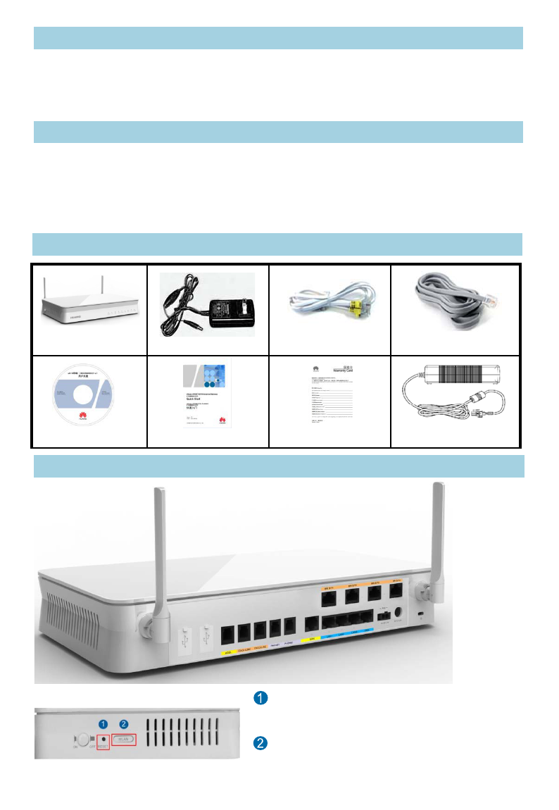
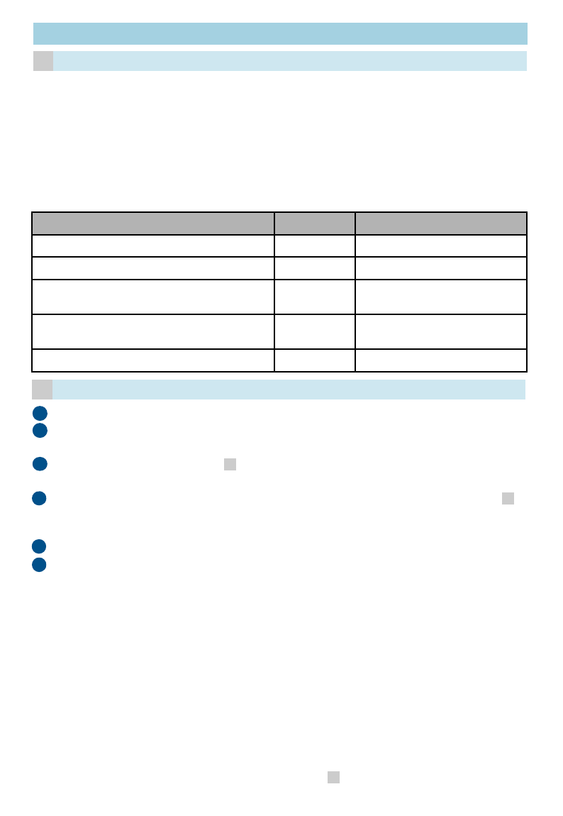
Packing List
z
P
ower o
ff
th
e
d
ev
i
ce, remove a
ll
connec
t
maintenance personnel if smokes, noise
s
EGW1530B Power supply adapter
A
Device Appearance
Rear View
Quick Start
Document CD-ROM
1
R
r
e
r
e
W
e
n
ti
m
Side View
e
Gateway (EGW1530B). This document
E
GW1530B. For more information, please
Gateway Product Documentation provided
void electric shock and other potential risks.
w
ith this product.
ut the device cable.
td bl d t t th i d
t
e
d
ca
bl
es, an
d
con
t
ac
t
au
th
or
i
ze
d
s
, or odors come from the device.
Network cable (1)
A
nalog phone lines (3)
Warranty Card PoE Power(optional)
1
ESET: Press the button for short time (≤ 6s) to
e
start. Press the button for long time (> 6s) to
e
store factory settings.
W
LAN: Press the button for short time (≤ 6s) to
n
able or disable WLAN. Press the button for long
m
e (> 6s) to activate WPS.
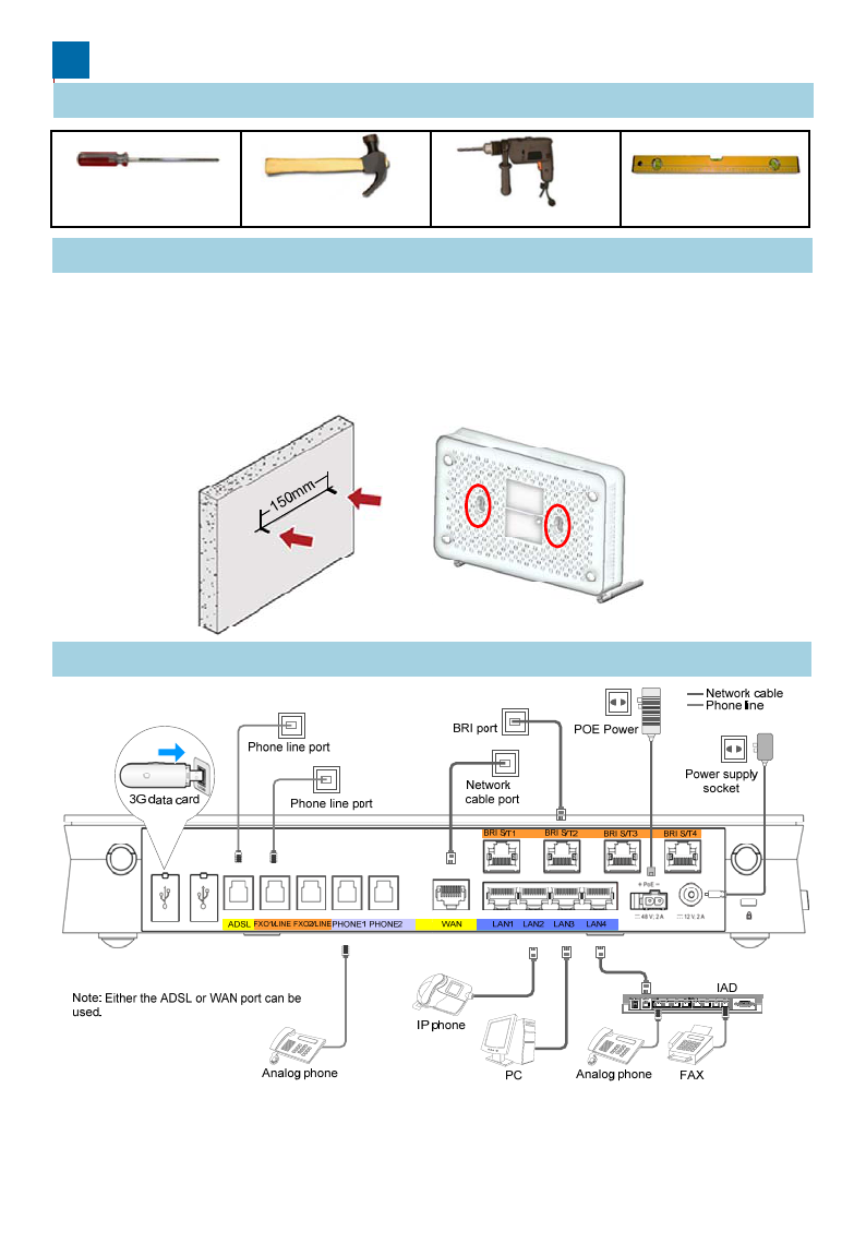
Installation
1 Preparing Installation Tools
Install the EGW1530B on a horizontal surfa
c
z
I t lli th
EGW1530B
hi tl
2 Installing the EGW1530B
Phillips screwdriver Claw hammer
z
I
ns
t
a
lli
ng
th
e
EGW1530B
on a
h
or
i
zon
t
a
l
on the surface and leave 10 cm space a
r
zTo install the EGW1530B on a wall, fix t
h
of the swell fixtures is exposed for moun
t
3 Connecting Cables
2
After cables are connected, press the powe
the POWER indicators (on the front panel)
a
If the POWER indicator is steady, the EGW
c
e or on a wall.
lf i Y l dtl it
Hammer drill Level ruler
l
sur
f
ace
i
s easy.
Y
ou on
l
y nee
d
t
o p
l
ace
it
r
ound for heat dissipation.
h
e swell fixtures (M4) and ensure that 5 mm
t
ing the EGW1530B.
2
r button to power on the EGW1530B. View
a
nd check the EGW1530B working status.
1530B is working properly.
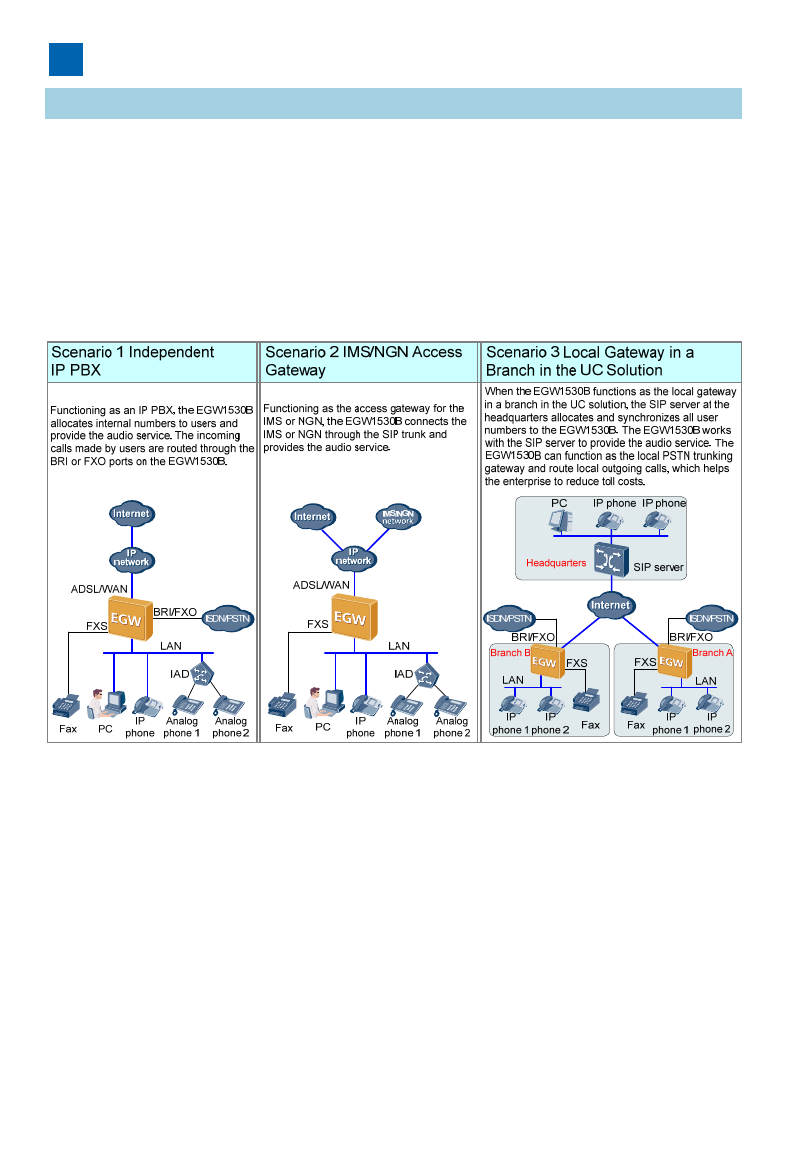
Configuring the EGW1530
B
Scenario Description
The audio function of the EGW1530B is us
e
independent IP PBX, IMS/NGN access gat
e
UC solution. The following describes the co
n
This chapter describes the Internet access
a
EGW1530B supports Internet access throu
g
methods are available: account and passw
o
Internet access mode and data, contact yo
u
details about scenario description and confi
g
ROM delivered with devices.
3
B
e
d in one of the following scenarios:
e
way, and local gateway in a branch in the
n
figuration methods in these scenarios. For
a
nd voice functions of the EGW1530B. The
g
h ADSL or WAN. In WAN mode, three
o
rd, static IP, and DHCP. For the specific
u
r local network carrier.
g
uration cases, see the documentation CD-
3
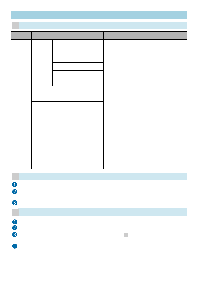
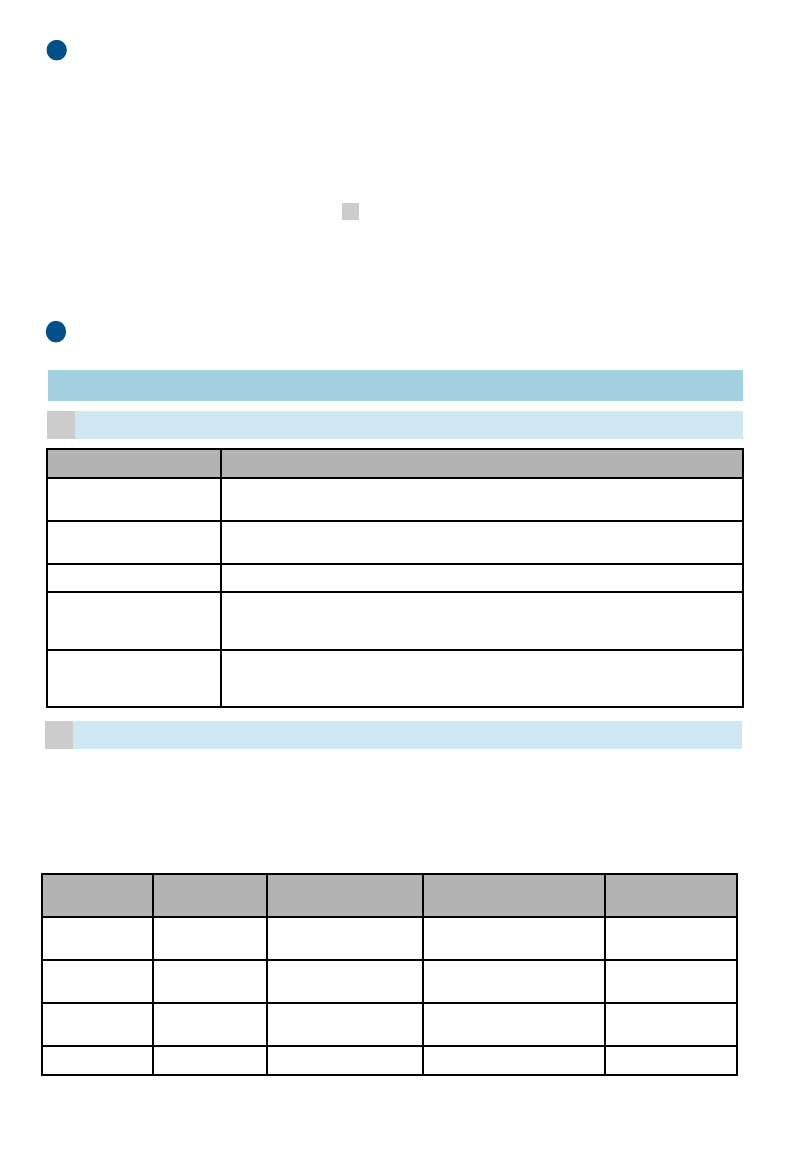
Planning Network Access Informati
o
Item Parameter
WAN
Account
PPPoE user name
PPPoE password
Static IP
WAN IP address
WAN subnet mask
a
Starting Configuration ——Netw
o
WAN gateway IP address
Primary DNS server
DHCP
ADSL
PVC Identifier (VPI)
PVC Identifier (VCI)
PPPoE user name
PPPoE password
Wireless
SSID
Wireless
function
Wireless access password
cStarting Configuration
bLogging In to the Web Managemen
t
Connect a PC to a LAN port on the EG
W
Log in to the EGW1530B using Internet
E
The default URL is https://192.168.1.1.
Enter the user name (admin) and pass
w
4
Choose Quick Setup from the navigatio
n
Choose a country and click Next.
Select a network connection mode acco
r
and click Next. Verify parameter settings
Click Save And Continue and configure
does not need to be configured, click Sa
v
4
o
n
Planning Description
o
rking
ADSL and WAN are available.
The WAN modes include the account, static
IP, and DHCP submodes.
To obtain the network access mode and
data, contact the local network carrier.
Indicates the ID of the EGW1530B. The ID
is displayed on a Wi-Fi terminal after the
terminal finds the EGW1530B. The default
ID is eSpace EGW_****. **** is the last four
digits in the WLAN MAC address
digits
in
the
WLAN
MAC
address
.
The password is a string consisting of 8 to
63 ASCII characters or 64 hexadecimal
digits. The default password is the WLAN
MAC address of the EGW1530B.
t
System
W
1530B using a network cable.
E
xplorer 6.0 or a later version on the PC.
w
ord (default: Admin@123) and click Log In.
4
n
tree on the web management system.
r
ding to step , set relevant parameters,
.
the audio function. If the audio function
v
e And Exit to exit the configuration wizard.
a
Starting Configuration —— Inde
p
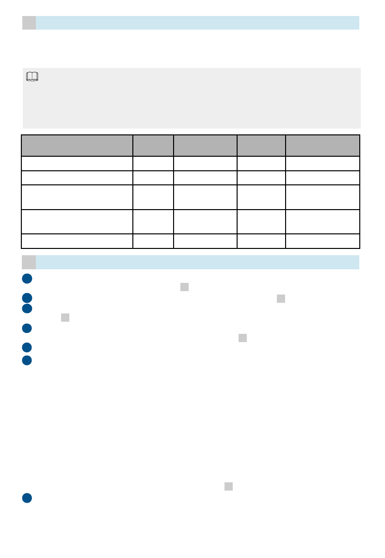
aPlanning Users' Internal Numbers
Analog phones, fax machines, IP phones, a
n
EGW1530B. You are advised to connect fa
x
PHONE port.
When the EGW1530B functions as an inde
p
outgoing prefix plus the called number to m
a
through the FXO ports or BRI ports.
The default outgoing prefix is 888. The outg
o
called number change rule in outgoing calls.
An internal number is a string of 1 to 30 digit
Phone Type
Fax machine or analog phone
IP phone
Analog phone 1 (connected to the
EGW1530B through the IAD)
Analog phone 2 (connected to the
EGW1530B through the IAD)
...
An
internal
number
is
a
string
of
1
to
30
digit
O
S
S
C
Starting Configuration
b
Configure the IAD. The following describ
e
1. Open Internet Explorer and enter the
the address box.
2
Et th (df lt
t
)
4
5
3
O
n the
S
IP
S
erve
r
page, disable the U
C
Click Next to access the analog phone c
o
not need to be configured when the EG
W
Based on the data plan in step , config
leave the registration groups and extern
a
Click Add in the right part of the IP Phon
, configure internal numbers of SIP users
external numbers blank, and click Next.
Click Finish to finish EGW1530B configu
2
1
6
a
5
2
.
E
n
t
er
th
e user name
(d
e
f
au
lt
: roo
t
)
a
n
Log In to access the web manageme
3. Choose Basic Configuration > Net
w
mode. Set the IAD IP address to 192.
port on the EGW1530B: 192.168.1.1)
and set the IP address of the default
g
4. Choose SIP Service Configuration
>
SIP server to the IP address of the L
A
192.168.1.1).
5. Choose SIP Service Configuration
>
user numbers) based on the data pla
n
p
endent IP PBX
n
d IADs can be connected to the
x
machines to the EGW1530B through the
p
endent IP PBX, users can dial the
a
ke an outgoing call, and the call is routed
o
ing prefix is deleted according to the
ts
User Type Internal Number Example
POTS user 6001
SIP user 6002
SIP user 6003
SIP user 6004
... ...
ts
.
e
s how to configure IAD208E(M).
IAD IP address (default: 192.168.100.1) in
dd(dflt
di
)dlik
mode and click Next.
o
nfiguration page. Registration groups do
W
1530B functions as the IP PBX.
ure internal numbers of POTS users,
a
l numbers blank, and click Next.
epage. Based on the data plan in step
, leave the registration groups and
ration.
a
5
nd
passwor
d
(d
e
f
au
lt
: a
d
m
i
n
)
an
d
c
li
c
k
nt page.
w
ork Paramete
r
and select the static IP
168.1.x(default IP address of the LAN
, set the subnet mask to 255.255.255.0,
g
ateway to 192.168.1.1.
>
SIP Server and set the IP address of the
A
N port on the EGW1530B (for example,
>
FXS User and set User ID (indicating
n
in step .
a
Configure an IP phone. The following de
s
phone. For details about other models, s
e
1. Enter the IP address of the IP phone
i
can click OK on the IP phone to view
2. Enter the user name and password (
d
and click Log In to access the web m
3. Click the Account tab. Set Register
N
based on the data plan in step . S
e
address of the LAN port on the EGW
1
4. Click Submit to finish IP phone confi
g
You can choose
Voice > Phone Alloc
7
a
You
can
choose
Voice
>
Phone
Alloc
system of the EGW1530B to view th
e
Verify the configuration according to the
c
document.
8
Starting Configuration —— IMS/
N
aPlanning SIP Server Data
Item Description
Type of the SIP server
address
The address can be an IP
from the network carrier.
SIP server address IP address or domain na
m
network carrier. For exam
p
SIP ser er t pe
The options are
NGN
and
SIP
ser
v
er
t
y
pe
The
options
are
NGN
and
Heartbeat detection
interval
Interval for the EGW1530
B
server, in seconds. The v
a
recommended.
Registration interval
Interval for the registratio
n
this group to the SIP serv
e
The value ranges from 0 t
o
Assume that the EGW1530B connects to th
e
user-by-user registration.
To obtain the registration group type, trunk r
e
name, IMS domain name, external numbers
,
network carrier. When the SIP server t
yp
e is
Planning the Registration Group
b
6
yp
Registration
Group ID Registration
Group Type Trunk Registrati
o
User ID
0User-by-user
registration +8657187654321
1User-by-user
registration +8657187654322
2User-by-user
registration +8657187654323
... ... ...
s
cribes how to configure an eSpace 78xx IP
e
e the appropriate administrator guide.
i
n the address box of Internet Explore
r
(You
the IP address of the IP phone).
d
efault values: admin) of the administrator
anagement page.
N
ame to the user number of the IP phone
e
t SIP Server to 192.168.1.1 (default IP
1
530B).
g
uration.
cation > IP Phone
in the web management
cation
>
IP
Phone
in
the
web
management
e
registration status of the IP phone.
c
hapter Verifying Configuration in this
N
GN Access Gateway
address and or a domain name. Obtain the type
m
e of the SIP server. Obtain the address from the
p
le, the value can be 191.1.1.1 or m04.huawei.com.
IMS
Obtain the t pe from the net ork carrier
IMS
.
Obtain
the
t
y
pe
from
the
net
w
ork
carrier
.
B
to send heartbeat messages to the active SIP
a
lue ranges from 10 to 900. The default value 60 is
n
group to send registration messages for users in
e
r, in seconds.
o
14400. The default value 360 is recommended.
e
IMS, and the registration group type is
e
gistration user ID, trunk registration user
,
Authentication and Password, contact the
NGN
,
leave the IMS domain name blank.
6
,
o
n Trunk Registration
User Name IMS Domain
Name
+8657187654321@abc.
def.com abc.def.com
+8657187654322@abc.
def.com abc.def.com
+8657187654323@abc.
def.com abc.def.com
... ...
Planning User Numbers
c
Analog phones, fax machines, IP phones, a
n
EGW1530B. You are advised to connect fa
x
PHONE port.
It
zThe ID of the registration group correspo
n
the same as that of the the trunk registration
u
with +, you need to change + to 00 when yo
u
zInternal numbers can be customized.
NOTE
User User Type
I
n
t
er
n
Exa
m
Fax machine or analog phone POTS user 6001
IP phone SIP user 6002
Analog phone 1 (connected to the
EGW1530B through the IAD) SIP user 6003
Analog phone 2 (connected to the
EGW1530B through the IAD) SIP user 6004
... ... ...
On the
SIP
S
erver
page disable the UC
1
Starting Configuration
d
4
5
3
On
the
SIP
S
erver
page
,
disable
the
UC
server based on the data plan in step
Configure the registration group based o
n
Configure the POTS user's internal and
e
in step and click Next.
Click Add in the right part of the IP Phon
and external numbers based on the data
Click Finish to finish EGW1530B configu
2
1
6Configure the IAD. The following describ
e
1. Open Internet Explorer and enter the
the address box.
2. Enter the user name (default: root) a
n
Log In to access the web manageme
3. Choose Basic Configuration > Net
w
mode Set the IAD IP address to
192
a
c
7
mode
.
Set
the
IAD
IP
address
to
192
.
port on the EGW1530B: 192.168.1.1)
,
and set the IP address of the default
g
4. Choose SIP Service Configuration
>
SIP server to the IP address of the L
A
192.168.1.1).
5. Choose SIP Service Configuration
>
user numbers) based on the data pla
n
Configure an IP phone. The following de
s
phone.
1. Enter the IP address of the IP phone
i
can click OK on the IP phone to view
7
n
d IADs can be connected to the
x
machines to the EGW1530B through the
lN b
Ritti
Et lN b
n
ding to an external number of a user must be
u
ser ID. If the trunk registration user ID starts
u
configure an external number.
n
a
l
N
um
b
er
m
ple
R
eg
i
s
t
ra
ti
on
Group ID
E
x
t
erna
l
N
um
b
er
Example
0 008657187654321
1 008657187654322
2 008657187654323
3 008657187654324
... ...
mode and click
Add
Configure the SIP
mode
and
click
Add
.
Configure
the
SIP
and click Next.
n
the data plan in step and click Next.
e
xternal numbers based on the data plan
e page. Configure the SIP users' internal
plan in step and click Next.
ration.
e
s how to configure IAD208E(M).
IAD IP address (default: 192.168.100.1) in
n
d password (default: admin) and click
nt page.
w
ork Paramete
r
and select the static IP
168 1
x
(default IP address of the LAN
b
c
7
168
.
1
.
x
(default
IP
address
of
the
LAN
,
set the subnet mask to 255.255.255.0,
g
ateway to 192.168.1.1.
>
SIP Server and set the IP address of the
A
N port on the EGW1530B (for example,
>
FXS User and set User ID (indicating
n
in step .
s
cribes how to configure an eSpace 78xx IP
i
n the address box of Internet Explore
r
(You
the IP address of the IP phone).
c

8Verify the configuration according to the
c
document.
2. Enter the user name and password (
d
and click Log In to access the web m
3. Click the Account tab. Set Register
N
based on the data plan in step . S
e
address of the LAN port on the EGW
1
4. Click Submit to finish IP phone confi
g
You can choose
V
oice > Phone Allo
c
management system of the EGW153
0
phone.
c
Server Type Planned Item Remarks
Starting Configuration —— Loca
Solution
aPlanning Server Information
When the EGW1530B functions as the loca
the SIP server on the central node at the h
e
synchronizes them to the EGW1530B. You
the EGW1530B.
Before configuration, collect user quantity i
n
allocation to the enterprise IT administrator.
The default outgoing prefix of the EGW153
0
according to the called number change rule
Data
synchronization
server
IP address Contact the
e
address of th
Port number
Contact the
e
number of th
e
number fails
t
Key for data
synchronization
The EGW15
3
that of the d
a
same, the da
the EGW153
0
synchronizati
including digi
negotiate wit
h
format.
SIP server
address
The address
Obtain the a
d
8
SIP server
SIP server type
The options
a
enterprise IT
When the SI
P
When the SI
P
Heartbeat
detection
interval
Interval for th
the active an
d
ranges from
3
recommende
Registration
interval
Interval for th
messages fo
r
seconds. Th
e
value 360 is
r
c
hapter Verifying Configuration in this
d
efault values: admin) of the administrator
anagement page.
N
ame to the user number of the IP phone
e
t SIP Server to 192.168.1.1 (default IP
1
530B).
g
uration.
c
ation > IP Phone in the web
0
B to view the registration status of the IP
l Gateway in a Branch in the UC
l gateway in a branch in the UC solution,
e
adquarters allocates all user numbers and
do not need to configure user numbers on
n
the branch and apply for number
0
B is 888. The outgoing prefix is deleted
in outgoing calls.
e
nterprise IT administrator to obtain the IP
e data synchronization server.
e
nterprise IT administrator to obtain the port
e
data synchronization server. If the port
t
o be obtained, use the default value 8098.
3
0B compares its data synchronization key with
a
ta synchronization server. If the keys are the
ta synchronization server synchronizes data to
0
B; otherwise, the EGW1530B rejects the data
on. The key is a string of 1 to 22 characters
ts, letters, or special characters. You can
h
the enterprise IT administrator about the key
can be an IP address and or a domain name.
d
dress from the enterprise IT administrator.
8
a
re IMS or NGN. Obtain the type from the
administrator.
P
server is eSpace U1960, select NGN.
P
server is eSpace U2900, select IMS.
e EGW1530B to send heartbeat messages to
d
standby SIP servers, in seconds. The value
3
0 to 150. The default value 90 is
d.
e registration group to send registration
r
users in this group to the SIP server, in
e
value ranges from 0 to 14400. The default
r
ecommended.

3
On the SIP server page, enable the UC
m
server based on the data plan in step .
Click Add. Configure the SIP server bas
e
Click Finish.
You can choose Voice > Phone Allocat
i
EGW1530B to view the synchronized us
e
2
1
Starting Configuration
b
a
When configuring the IP phone, set SIP server 1, SIP
the central node, standby SIP server in the central no
d
NOTE
Verifying Configuration
You can visit a website (for example, http://
e
network function. If the access is successful
,
configured.
aVerifying Network Access
Verifying the Audio Function
b
Verify the configuration according to the
c
document.
4
zIndependent IP PBX
• Intra-office users dial each other's inte
r
f
numbers con
f
igured.
• An intra-office user under the EGW153
number (for example, mobile phone nu
• An outer-office user dials the number t
h
FXO port of the EGW1530B. After hea
r
switchboard, the outer-office user dials
number).
zIMS/NGN access gateway
• Intra-office users dial each other's inte
r
numbers configured.
• Calls are made between an analog ph
o
a network-side number (for example, a
z
Local gateway in a branch in the UC solu
9
z
Local
gateway
in
a
branch
in
the
UC
solu
• Intra-office users dial each other's inte
r
numbers configured.
• An intra-office user under the EGW153
number (for example, mobile phone nu
• An outer-office user dials the number t
h
FXO port of the EGW1530B. After hea
r
switchboard, the outer-office user dials
number).
In the preceding scenarios, verify that the c
a
fails, check the configuration and cable con
n
m
ode. Configure the data synchronization
e
d on the data plan in step and click Next.
i
on in the web management system of the
e
r number.
a
server 2, and SIP server 3 to the active SIP server in
d
e, and IP address of the LAN port on the EGW1530B.
e
nterprise.huawei.com) and verify the
,
the network function is correctly
c
hapter Verifying Configuration in this
r
nal numbers using phones that have
0B to dial the outgoing prefix (888) and the
mber) of an oute
r
-office user.
h
at the PSTN network carrier assigns to the
r
ing the announcement played by the
the extension number (that is, the internal
r
nal numbers using phones that have
o
ne or IP phone under the EGW1530B and
mobile phone number).
ution
9
ution
r
nal numbers using phones that have
0B to dial the outgoing prefix (888) and the
mber) of an oute
r
-office user.
h
at the PSTN network carrier assigns to the
r
ing the announcement played by the
the extension number (that is, the internal
a
lls are connected successfully. If a call
n
ection.
Seeking Technical Support and
O
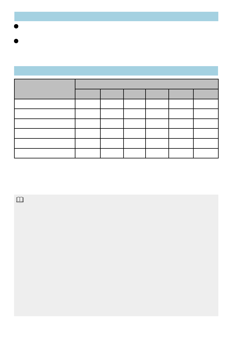
Declaration on Hazardous Subst
a
Products
Parts
Hazardous Subst
Contact the device supplier to obtain tec
h
Technical support
Documentation
Obtain documentation from the CD-ROM
SUPPORT > Products > UC&C > UC >
obtain documentation.
Parts
Hazardous
Subst
Pb Hg
Mechanical part ×○
Board/circuit module ×○
Signal cable ×○
Cable connector ×○
Power adapter ×○
Auxiliary equipment ×○
○:Indicates that the concentration of the haz
h t i l fthi ti b l th
h
omogeneous ma
t
er
i
a
l
s o
f
thi
s par
t
i
s
b
e
l
ow
the
standard.
×: Indicates that the concentration of the haz
homogeneous materials of this part is above th
e
1. Mechanical part such as shell: The steel, aluminu
m
2. Board and circuit module:
zThe PCB pad contains lead.
zCeramic capacitor or feedthrough capacitor or
ceramic chip contains lead.
zThe resistor inside the clock oscillator is imm
u
zThe high temperature type solder, used for the
contains more than 85% lead.
NOTE
1
contains
more
than
85%
lead.
zThe luminescence glass of chip inductor conta
i
zThe high temperature type solder used for the
t
zThe glass of resistance layer and protection la
y
zThe pin and solder of the components such as
t
3. Signal cables: The alloy materials such as the stee
l
contain lead.
4. Cable connector: For most connectors, the metal s
h
5. Power adapter: The interior contains lead.
6.The circuit board of the auxiliary equipment contai
n
two.
O
btaining Documentation
a
nces in Electronic Information
tances
h
nical support.
delivered with the device o
r
choose
UC in http://enterprise.huawei.com to
tances
Cd Cr6+ PBB PBDE
○○ ○ ○
○○ ○ ○
○○ ○ ○
○○ ○ ○
○○ ○ ○
○○ ○ ○
ardous substance contained in all the
li it i t f th SJ/T 11363 2006
e
li
m
it
requ
i
remen
t
o
f
th
e
SJ/T
11363
−
2006
ardous substance contained in all the
e
limit requirement.
m
or copper materials contain lead.
mica capacitor on the board: The
u
ne from lead.
connector inside the transformer,
0
i
ns lead.
t
ransistor chip contains lead.
y
er is immune from lead.
t
he IC and power unit contain lead.
l
, aluminum, and copper materials
h
ell, terminal and pin contain lead.
n
s lead. Same as point one and poin
t