Huawei Technologies EPICO3801 UMTS Enhanced Pico Base Station User Manual User Guide
Huawei Technologies Co.,Ltd UMTS Enhanced Pico Base Station User Guide
User Manual

ePico3801
V200R011C00
User Guide
Issue 01
Date 2009–09–23
Huawei Proprietary and Confidential
Copyright © Huawei Technologies Co., Ltd.

Huawei Technologies Co., Ltd. provides customers with comprehensive technical support and service. For any
assistance, please contact our local office or company headquarters.
Huawei Technologies Co., Ltd.
Address: Huawei Industrial Base
Bantian, Longgang
Shenzhen 518129
People's Republic of China
Website: http://www.huawei.com
Email: support@huawei.com
Copyright © Huawei Technologies Co., Ltd. 2009. All rights reserved.
No part of this document may be reproduced or transmitted in any form or by any means without prior written
consent of Huawei Technologies Co., Ltd.
Trademarks and Permissions
and other Huawei trademarks are the property of Huawei Technologies Co., Ltd.
All other trademarks and trade names mentioned in this document are the property of their respective holders.
Notice
The information in this document is subject to change without notice. Every effort has been made in the
preparation of this document to ensure accuracy of the contents, but the statements, information, and
recommendations in this document do not constitute a warranty of any kind, express or implied.
Huawei Proprietary and Confidential
Copyright © Huawei Technologies Co., Ltd.

Contents
About This Document.....................................................................................................................1
1 Changes in the ePico3801 User Guide....................................................................................1-1
2 Introduction to the ePico3801...................................................................................................2-1
2.1 Position of the ePico3801 on the Network of the uBro Solution....................................................................2-2
2.2 Features of the ePico3801...............................................................................................................................2-3
2.3 Composition of the ePico3801........................................................................................................................2-5
2.3.1 ePico3801 Body.....................................................................................................................................2-5
2.3.2 Power Adapter........................................................................................................................................2-9
2.4 Specifications of the ePico3801....................................................................................................................2-12
2.4.1 Performance Specifications..................................................................................................................2-12
2.4.2 Physical and Electrical specifications..................................................................................................2-14
2.5 Application Scenarios...................................................................................................................................2-15
2.5.1 Access Networking Scenarios..............................................................................................................2-16
2.5.2 Installation Scenarios...........................................................................................................................2-17
2.5.3 Typical Application Scenarios.............................................................................................................2-18
3 ePico3801 Initial Configuration...............................................................................................3-1
3.1 Logging in to the ePico WebUI.......................................................................................................................3-2
3.2 Configuring the ePico3801..............................................................................................................................3-3
4 Commissioning the ePico3801.................................................................................................4-1
4.1 Commissioning Procedure..............................................................................................................................4-2
4.2 Checking the Hardware Status........................................................................................................................4-3
4.3 Checking the Network Transmission..............................................................................................................4-5
4.4 Checking the Software Version.......................................................................................................................4-7
4.5 Checking the Running Status..........................................................................................................................4-8
4.6 Testing Services..............................................................................................................................................4-8
4.7 Data Sheet for Commissioning.......................................................................................................................4-9
4.8 Communication Ports on the ePico3801.......................................................................................................4-10
5 Reconfiguring the ePico3801....................................................................................................5-1
5.1 Configuring Automatic Network Planning Parameters..................................................................................5-2
5.2 Setting ePico Cell Parameters.........................................................................................................................5-3
5.3 Modifying Automatic Pilot Adjustment Parameters.......................................................................................5-4
ePico3801
User Guide Contents
Issue 01 (2009–09–23) Huawei Proprietary and Confidential
Copyright © Huawei Technologies Co., Ltd.
i

5.4 Adjusting Mobility Management Parameters.................................................................................................5-5
5.4.1 Modifying 3G Macro Neighboring Cells...............................................................................................5-5
5.4.2 Modifying 2G Macro Neighboring Cells...............................................................................................5-6
5.4.3 Modify HCS Reselection Parameters.....................................................................................................5-7
5.4.4 Modifying Signal Quality Offset Reselection Parameters.....................................................................5-8
5.4.5 Modifying the ePico3801 Parameters Related to the Handover to 3G Macro Cells..............................5-8
5.4.6 Modifying the ePico3801 Parameters Related to the Handover to 2G Macro Cells..............................5-9
5.5 Adjusting the Transport Network....................................................................................................................5-9
5.5.1 Modifying Clock Synchronization Parameters....................................................................................5-10
5.5.2 Modifying Transmission Parameters...................................................................................................5-11
5.5.3 Modifying the VLAN Attributes..........................................................................................................5-12
5.6 Adjusting the ePico3801 Functions...............................................................................................................5-13
5.6.1 Modifying the HSPA Status.................................................................................................................5-13
5.6.2 Configuring the Emergency Call Redirection Switch..........................................................................5-14
5.6.3 Modifying the Access Reject Reason...................................................................................................5-14
5.6.4 Modifying the Location Indication Mode............................................................................................5-15
5.6.5 Setting the Differentiated Billing Parameters......................................................................................5-16
5.6.6 Configuring the Locating Function......................................................................................................5-16
6 Maintaining the ePico3801....................................................................................................... 6-1
6.1 ePico3801 Routine Maintenance Items...........................................................................................................6-2
6.2 Powering On and Powering Off the ePico3801..............................................................................................6-2
6.2.1 Powering On the ePico3801...................................................................................................................6-3
6.2.2 Powering Off the ePico3801..................................................................................................................6-4
6.3 Replacing the ePico3801.................................................................................................................................6-4
Index.................................................................................................................................................i-1
Contents
ePico3801
User Guide
ii Huawei Proprietary and Confidential
Copyright © Huawei Technologies Co., Ltd.
Issue 01 (2009–09–23)

Figures
Figure 2-1 Position of the ePico3801 on the network of the uBro solution.........................................................2-2
Figure 2-2 Two ePico3801s, one with a built-in antenna and the other with an external antenna.......................2-6
Figure 2-3 Ports and buttons on the panel of the ePico3801................................................................................2-7
Figure 2-4 LEDs of the ePico3801.......................................................................................................................2-8
Figure 2-5 AC/DC power adapter......................................................................................................................2-10
Figure 2-6 PSE...................................................................................................................................................2-11
Figure 2-7 Networking in modem access mode.................................................................................................2-16
Figure 2-8 Networking in LAN access mode.....................................................................................................2-17
Figure 2-9 Typical installation scenarios of the ePico3801...............................................................................2-18
Figure 2-10 Application of the ePico3801 in an SME.......................................................................................2-19
Figure 3-1 Logging in to the WebUI....................................................................................................................3-3
Figure 4-1 Commissioning procedures................................................................................................................4-3
ePico3801
User Guide Figures
Issue 01 (2009–09–23) Huawei Proprietary and Confidential
Copyright © Huawei Technologies Co., Ltd.
iii

Tables
Table 2-1 Functions of the ports and buttons of the ePico3801...........................................................................2-7
Table 2-2 Status of the LEDs of the ePico3801...................................................................................................2-8
Table 2-3 Specifications and parameters of the AC/DC power adapter.............................................................2-10
Table 2-4 Ports on the PSE.................................................................................................................................2-11
Table 2-5 LEDs on the PSE................................................................................................................................2-11
Table 2-6 Specifications and parameters of the PSE..........................................................................................2-12
Table 2-7 RF specifications of the ePico3801....................................................................................................2-12
Table 2-8 Service capabilities of the ePico3801................................................................................................2-13
Table 2-9 Physical specifications of the ePico3801...........................................................................................2-14
Table 2-10 Power Consumption Specifications of the ePico3801.....................................................................2-15
Table 2-11 Environmental specifications of the ePico3801...............................................................................2-15
Table 4-1 Tools for ePico3801 commissioning....................................................................................................4-2
Table 4-2 Normal status of the LEDs...................................................................................................................4-4
Table 4-3 Abnormal status of the LEDs...............................................................................................................4-4
Table 4-4 Basic items in the service test..............................................................................................................4-9
Table 4-5 Data sheet for commissioning..............................................................................................................4-9
Table 4-6 Communication ports on the ePico3801............................................................................................4-10
Table 6-1 Maintenance items for the equipment..................................................................................................6-2
ePico3801
User Guide Tables
Issue 01 (2009–09–23) Huawei Proprietary and Confidential
Copyright © Huawei Technologies Co., Ltd.
v

About This Document
Purpose
This document describes the ePico3801 in terms of its specifications, application scenarios,
initial configuration, commissioning, configuration adjustments, and routine maintenance.
Product Version
The following table lists the product version related to this document.
Product Name Product Version
ePico3801 V200R011C00
Intended Audience
This document is intended for:
lSystem engineers
lMaintenance engineers
lNetwork administrators
Change History
For changes in the document, see 1 Changes in the ePico3801 User Guide.
Organization
1 Changes in the ePico3801 User Guide
This describes the changes in the ePico3801 User Guide.
2 Introduction to the ePico3801
The ePico3801 is a pico base station used as the radio access device in the uBro solution to
enhance indoor coverage. Being one of a series of ePico products developed according to the
FDD protocols in 3GPP R99/R4/R5/R6, the ePico3801 provides indoor users with improved
radio access services. By enhancing ordinary indoor coverage, intensive coverage in office
buildings, and hot-spot indoor coverage, the ePico3801 eliminates indoor dead zones and shares
the load on the macro network.
ePico3801
User Guide About This Document
Issue 01 (2009–09–23) Huawei Proprietary and Confidential
Copyright © Huawei Technologies Co., Ltd.
1
3 ePico3801 Initial Configuration
This chapter describes how to perform initial configuration of the ePico3801 on the WebUI so
that users can perform the configuration of the ePico3801 according to the access and
authentication mode.
4 Commissioning the ePico3801
This chapter describes the commissioning and verification after the installation of the ePico3801
hardware. The commissioning ensures that the ePico3801 works properly as designed.
5 Reconfiguring the ePico3801
This chapter describes common reconfiguration items during the normal running of the
ePico3801.
6 Maintaining the ePico3801
This chapter describes how to maintain the ePico3801. After the ePico3801 is put into use, you
need to perform routine maintenance on the ePico3801 to ensure the proper running of the
ePico3801.
Conventions
Symbol Conventions
The symbols that may be found in this document are defined as follows.
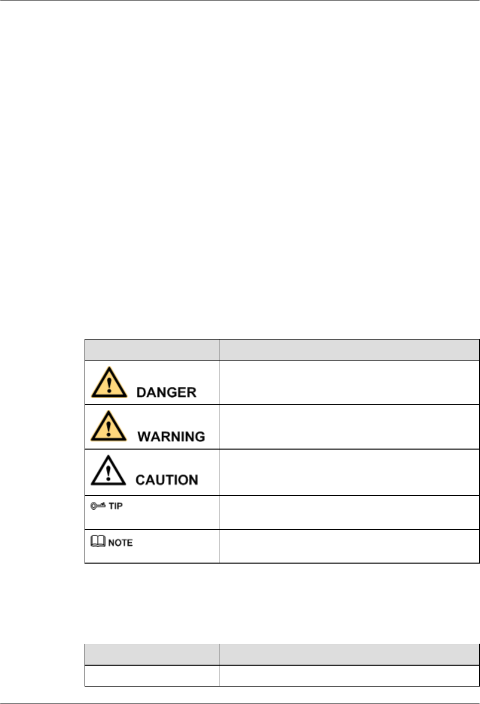
Symbol Description
Indicates a hazard with a high level of risk, which if not
avoided,will result in death or serious injury.
Indicates a hazard with a medium or low level of risk, which
if not avoided, could result in minor or moderate injury.
Indicates a potentially hazardous situation, which if not
avoided,could result in equipment damage, data loss,
performance degradation, or unexpected results.
Indicates a tip that may help you solve a problem or save
time.
Provides additional information to emphasize or supplement
important points of the main text.
General Conventions
The general conventions that may be found in this document are defined as follows.
Convention Description
Times New Roman Normal paragraphs are in Times New Roman.
About This Document
ePico3801
User Guide
2 Huawei Proprietary and Confidential
Copyright © Huawei Technologies Co., Ltd.
Issue 01 (2009–09–23)

Convention Description
Boldface Names of files, directories, folders, and users are in
boldface. For example, log in as user root.
Italic Book titles are in italics.
Courier New Examples of information displayed on the screen are in
Courier New.
Command Conventions
The command conventions that may be found in this document are defined as follows.
Convention Description
Boldface The keywords of a command line are in boldface.
Italic Command arguments are in italics.
[ ] Items (keywords or arguments) in brackets [ ] are optional.
{ x | y | ... } Optional items are grouped in braces and separated by
vertical bars. One item is selected.
[ x | y | ... ] Optional items are grouped in brackets and separated by
vertical bars. One item is selected or no item is selected.
{ x | y | ... }*Optional items are grouped in braces and separated by
vertical bars. A minimum of one item or a maximum of all
items can be selected.
[ x | y | ... ]*Optional items are grouped in brackets and separated by
vertical bars. Several items or no item can be selected.
GUI Conventions
The GUI conventions that may be found in this document are defined as follows.
Convention Description
Boldface Buttons, menus, parameters, tabs, window, and dialog titles
are in boldface. For example, click OK.
>Multi-level menus are in boldface and separated by the ">"
signs. For example, choose File > Create > Folder .
Keyboard Operations
The keyboard operations that may be found in this document are defined as follows.
ePico3801
User Guide About This Document
Issue 01 (2009–09–23) Huawei Proprietary and Confidential
Copyright © Huawei Technologies Co., Ltd.
3

Format Description
Key Press the key. For example, press Enter and press Tab.
Key 1+Key 2 Press the keys concurrently. For example, pressing Ctrl+Alt
+A means the three keys should be pressed concurrently.
Key 1, Key 2 Press the keys in turn. For example, pressing Alt, A means
the two keys should be pressed in turn.
Mouse Operations
The mouse operations that may be found in this document are defined as follows.
Action Description
Click Select and release the primary mouse button without moving
the pointer.
Double-click Press the primary mouse button twice continuously and
quickly without moving the pointer.
Drag Press and hold the primary mouse button and move the
pointer to a certain position.
About This Document
ePico3801
User Guide
4 Huawei Proprietary and Confidential
Copyright © Huawei Technologies Co., Ltd.
Issue 01 (2009–09–23)

1 Changes in the ePico3801 User Guide
This describes the changes in the ePico3801 User Guide.
01(2009-09-15)
This is the initial release.
ePico3801
User Guide 1 Changes in the ePico3801 User Guide
Issue 01 (2009–09–23) Huawei Proprietary and Confidential
Copyright © Huawei Technologies Co., Ltd.
1-1

2 Introduction to the ePico3801
About This Chapter
The ePico3801 is a pico base station used as the radio access device in the uBro solution to
enhance indoor coverage. Being one of a series of ePico products developed according to the
FDD protocols in 3GPP R99/R4/R5/R6, the ePico3801 provides indoor users with improved
radio access services. By enhancing ordinary indoor coverage, intensive coverage in office
buildings, and hot-spot indoor coverage, the ePico3801 eliminates indoor dead zones and shares
the load on the macro network.
2.1 Position of the ePico3801 on the Network of the uBro Solution
The ePico3801 is used as the radio access device in the uBro solution.
2.2 Features of the ePico3801
The ePcio3801 is an enhanced pico base station used for indoor coverage. It uses IP access and
supports HSPA. With the ePico3801, network planning and optimization are convenient, and
security is high. The ePico3801 makes it possible to deploy flexible and seamless UMTS network
coverage quickly.
2.3 Composition of the ePico3801
The ePico3801 consists of the ePico3801 body and the power adapter. The ePico3801 body
provides the LEDs, reset button, power port, and FE port. The ePico3801 supports the AC power
supply and Power over Ethernet (PoE) power supply, which require different power adapters.
2.4 Specifications of the ePico3801
The specifications of the ePico3801 involve its performance specifications, physical and
electrical specifications.
2.5 Application Scenarios
The ePico3801 is widely used for indoor coverage in small and medium enterprises (SMEs),
SOHOs, schools, and office buildings and for hot-spot indoor coverage at pubs, airports, stores,
and hotels.
ePico3801
User Guide 2 Introduction to the ePico3801
Issue 01 (2009–09–23) Huawei Proprietary and Confidential
Copyright © Huawei Technologies Co., Ltd.
2-1
2.1 Position of the ePico3801 on the Network of the uBro
Solution
The ePico3801 is used as the radio access device in the uBro solution.
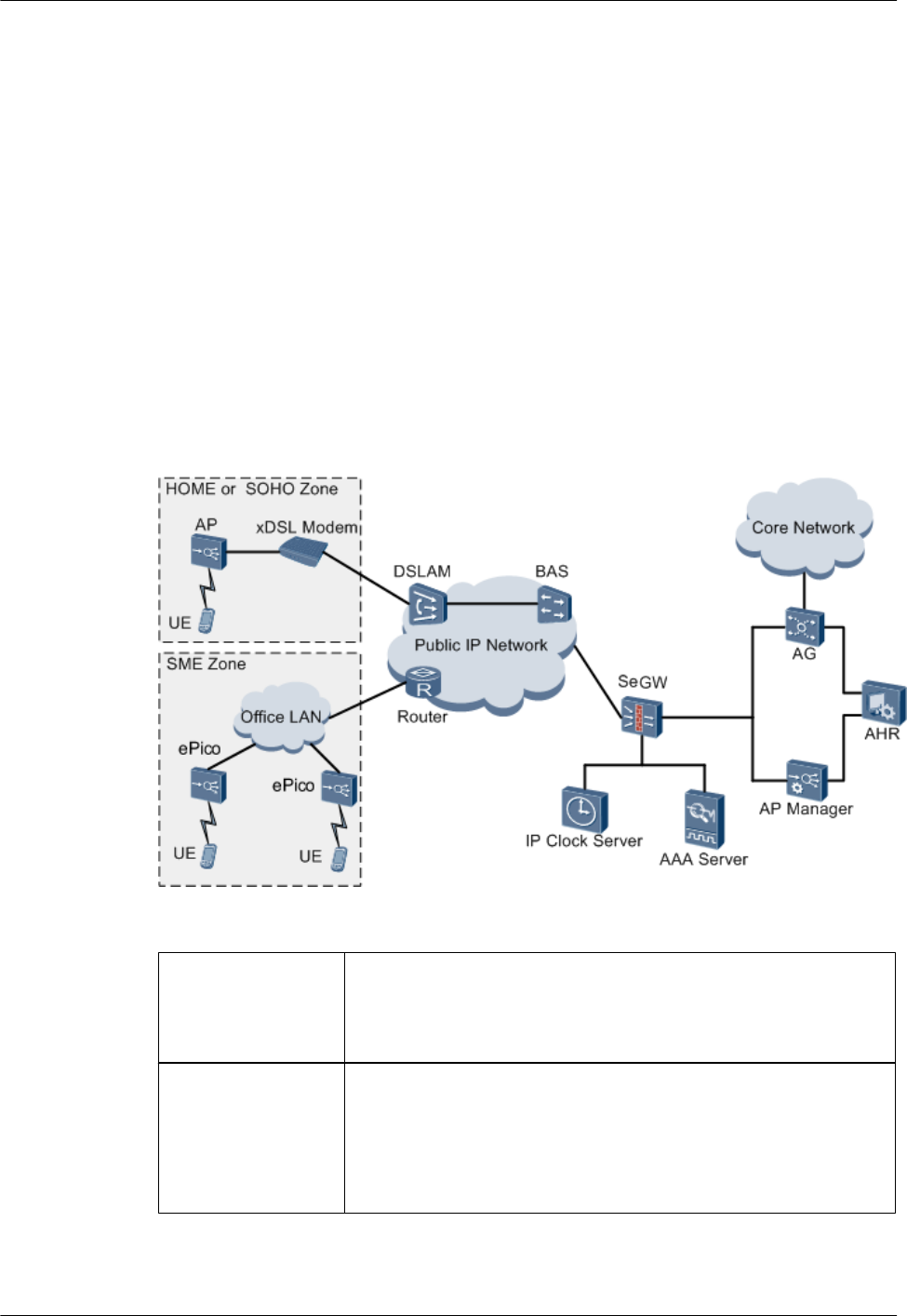
The uBro solution adds the ePico3801, Access Gateway (AG), AP Home Register (AHR), and
AP Manager to the existing UMTS network. The AG is responsible for controlling and managing
ePico3801s. It also provides routing towards the UMTS core network. The ePico3801 is
connected to the enterprise LAN or modem, the enterprise LAN or modem is connected to the
public IP network, and the public IP network is connected to the AG. In this way, the ePico3801
can communicate with the AG, which connects the ePico3801 to the UMTS core network. The
standard Uu interface is used between the ePico3801 and the UE to ensure compatibility with
existing commercial terminals. Figure 2-1 shows the position of the ePico3801 on the network
of the uBro solution.
Figure 2-1 Position of the ePico3801 on the network of the uBro solution
ePico3801 The functions of the ePico3801 are equivalent to the functions of the
NodeB plus some functions of the RNC. It serves as the UMTS radio
access device, performing radio modulation and demodulation, radio
resource management, and power control.
AG Used as the core network device in the uBro solution, the AG
performs the following functions:
lForwarding signaling messages on the control plane and data on
the user plane between the ePico3801 and the UMTS core network
lControlling and managing links for the ePico3801
2 Introduction to the ePico3801
ePico3801
User Guide
2-2 Huawei Proprietary and Confidential
Copyright © Huawei Technologies Co., Ltd.
Issue 01 (2009–09–23)

AHR Used as the home server of the ePico3801, the AHR performs the
following functions:
lProcessing ePico3801 user definition and cancellation and
managing subscription data
lImplementing centralized management of the admission control
lists of ePico3801s
lImplementing zone management for ePico3801s
lCompleting boot parameter settings for ePico3801s
lImplementing location detection and validity checks for
ePico3801s
AP Manager The AP Manager is located on the core network of the uBro solution
and is responsible for centralized management and maintenance of
ePico3801s on the entire network. The functions of the AP Manager
are alarm management, configuration management, fault
management, version management, software management, task
management, security management, and log management.
SeGW The security gateway (SeGW) is located at the entrance of the core
network of the uBro solution and performs the following functions:
lSupporting standard firewall functions to provide security
protection for the equipment on the core network of the uBro
solution
lSupporting the IP security protocol (IPSec) virtual private network
(VPN) tunneling function, through which the SeGW establishes
IPSec VPN tunnels between itself and ePico3801s to provide
security protection for communications between ePico3801s and
the network elements on the core network of the uBro solution
AAA The Authentication, Authorization and Accounting (AAA) performs
authentication for SIMs and USIMs.
UE The user equipment (UE) is the user terminal.
IP clock server The IP clock server provides clock sources for ePico3801s.
2.2 Features of the ePico3801
The ePcio3801 is an enhanced pico base station used for indoor coverage. It uses IP access and
supports HSPA. With the ePico3801, network planning and optimization are convenient, and
security is high. The ePico3801 makes it possible to deploy flexible and seamless UMTS network
coverage quickly.
Enhanced Indoor Coverage Improving User Experience
lDeployed in factories or office buildings, the ePico3801 achieves seamless coverage on
UMTS networks by solving the problem of poor penetration capabilities of the high UMTS
frequency bands.
ePico3801
User Guide 2 Introduction to the ePico3801
Issue 01 (2009–09–23) Huawei Proprietary and Confidential
Copyright © Huawei Technologies Co., Ltd.
2-3

lThe ePico3801 supports HSPA to provide high-speed stable data services. Users can easily
enjoy high-quality UMTS services.
High Usability Lowering Costs of Network Construction and Maintenance
lIn the uBro solution, ePico3801s used for single-point coverage are entirely Plug and Play
(PnP) devices. Therefore, the installation and commissioning of ePico3801s are convenient,
lowering the costs of deployment and optimization. With ePico3801s, a UMTS network
can be deployed quickly.
lIf installed in an office building, ePico3801s do not require a private equipment room. Users
install the ePico3801s and provide the power supply themselves. In addition, the
ePico3801s are easy to transport. Thus, the network construction costs of mobile operators
are lowered.
lUsing the IPSec tunneling mode, ePico3801s are connected to the core network through
the public IP network. The ePico3801s make full use of IP transmission resources and
guarantee security in IP transmission. Thus, network construction costs are significantly
lowered.
lUsing the AP manager, which is a uniform management and maintenance platform, the
ePico3801 automatically performs network discovery and parameter settings. The
ePico3801 supports intelligent network planning and optimization, and software upgrades
are automated. Thus, the usability is improved, and the network maintenance and
optimization costs are lowered.
Powerful Mechanism Guaranteeing Security
lUsing the IKEv2 protocol to perform IPSec negotiation, the ePico3801 supports EAP-SIM
and EAP-AKA authentication to guarantee network security.
lThe ePico3801 supports user management and admission control. Thus, unauthorized UEs
cannot use the ePico3801, and the user's investments are protected.
lThe emergency call function provides high security for users.
lFor the North American market, the ePico3801 meets the requirements for the E911
location function at a high precision. When a user dials an emergency number, the call
request is first processed by the public safety answering point (PSAP) and then quickly
forwarded to the local police department, emergency medical center, firefighting
department, or legislative agency. By determining the location of the UE through GPS, the
organization concerned can trace the user and provide help in time.
Variety of Functions Raising User Satisfaction
lThe ePico3801 supports AGPS.
lThe ePico3801 supports customized location indication functions to inform UEs of the
accurate network coverage. Compared with the macro UMTS network, the uBro network
covered by ePico3801s provides better coverage and enables mobile operators to offer
lower tariffs.
lHandovers and cell reselection can be performed between an ePico cell and a macro cell
to ensure that the user chooses a network that provides a higher service quality at a lower
tariff.
lThe ePico3801 supports static relocation that complies with the 3GPP Uu interface
protocol. In addition, The ePico3801 supports soft handovers to ensure service continuity
when UEs move, thus improving user experience.
2 Introduction to the ePico3801
ePico3801
User Guide
2-4 Huawei Proprietary and Confidential
Copyright © Huawei Technologies Co., Ltd.
Issue 01 (2009–09–23)

2.3 Composition of the ePico3801
The ePico3801 consists of the ePico3801 body and the power adapter. The ePico3801 body
provides the LEDs, reset button, power port, and FE port. The ePico3801 supports the AC power
supply and Power over Ethernet (PoE) power supply, which require different power adapters.
2.3.1 ePico3801 Body
The ePico3801 body consists of the ePico board, RF subboard, and plastic case. The ePico board
is responsible for the main control of the system and the processing of baseband signals. In
addition, the ePico board provides power supply for the RF unit and controls communication.
The RF subboard receives, transmits, and processes RF signals.
2.3.2 Power Adapter
The ePico3801 can use the AC power supply or power supply from the PoE function. When the
AC power supply is used, the PoE power supply system is shut down automatically. When the
AC power supply is used, the ePico3801 needs to be configured with the AC/DC power adapter.
When the PoE power supply is used, the ePico3801 needs to be configured with the power supply
equipment (PSE).
2.3.1 ePico3801 Body
The ePico3801 body consists of the ePico board, RF subboard, and plastic case. The ePico board
is responsible for the main control of the system and the processing of baseband signals. In
addition, the ePico board provides power supply for the RF unit and controls communication.
The RF subboard receives, transmits, and processes RF signals.
Exterior of the ePico3801
The ePico3801 takes the shape of a case. It contains a built-in RF subsystem, baseband
subsystem, transmission subsystem, control subsystem, and clock subsystem. The ePico3801
boasts a lower power consumption, compact structure, light weight, small size, and stylish
appearance.
The ePico3801 can be configured with an internal or external antenna, depending on the actual
requirements. Figure 2-2 shows two ePico3801s, one with a built-in antenna and the other with
an external antenna.
ePico3801
User Guide 2 Introduction to the ePico3801
Issue 01 (2009–09–23) Huawei Proprietary and Confidential
Copyright © Huawei Technologies Co., Ltd.
2-5

Figure 2-2 Two ePico3801s, one with a built-in antenna and the other with an external antenna
Ports and Buttons of the ePico3801
The ePico3801 provides a power port, FE port, USIM/SIM port, antenna port, LED, and reset
button.
Figure 2-3 shows the ports and buttons on the panel of the ePico3801.
2 Introduction to the ePico3801
ePico3801
User Guide
2-6 Huawei Proprietary and Confidential
Copyright © Huawei Technologies Co., Ltd.
Issue 01 (2009–09–23)

Figure 2-3 Ports and buttons on the panel of the ePico3801
Table 2-1 describes the functions of the ports and buttons of the ePico3801.
Table 2-1 Functions of the ports and buttons of the ePico3801
SN Port or Button Function
1LAN This port is used for both services and commissioning.
An Ethernet cable connected to this port connects the
ePico3801 to the Ethernet transmission equipment.
When the PoE power supply is used, this port is used
to provide the working power supply for the
ePico3801.
2PWR This port is connected to an AC/DC power adapter to
provide the 12 V DC power supply.
3 GPS This port is the external GPS antenna port.
4 ANT/A This port is the external UMTS antenna port.
5 SIM CARD This port is used to hold the USIM or SIM card.
ePico3801
User Guide 2 Introduction to the ePico3801
Issue 01 (2009–09–23) Huawei Proprietary and Confidential
Copyright © Huawei Technologies Co., Ltd.
2-7
SN Port or Button Function
6RST This button is used to reset the device. You can press
the RST button once to reset the ePico3801 or press
this button three times consecutively to restore the
factory settings of the ePico3801, such as the
password used to log in to the WebUI and the IP
address used for local maintenance of the ePico3801.
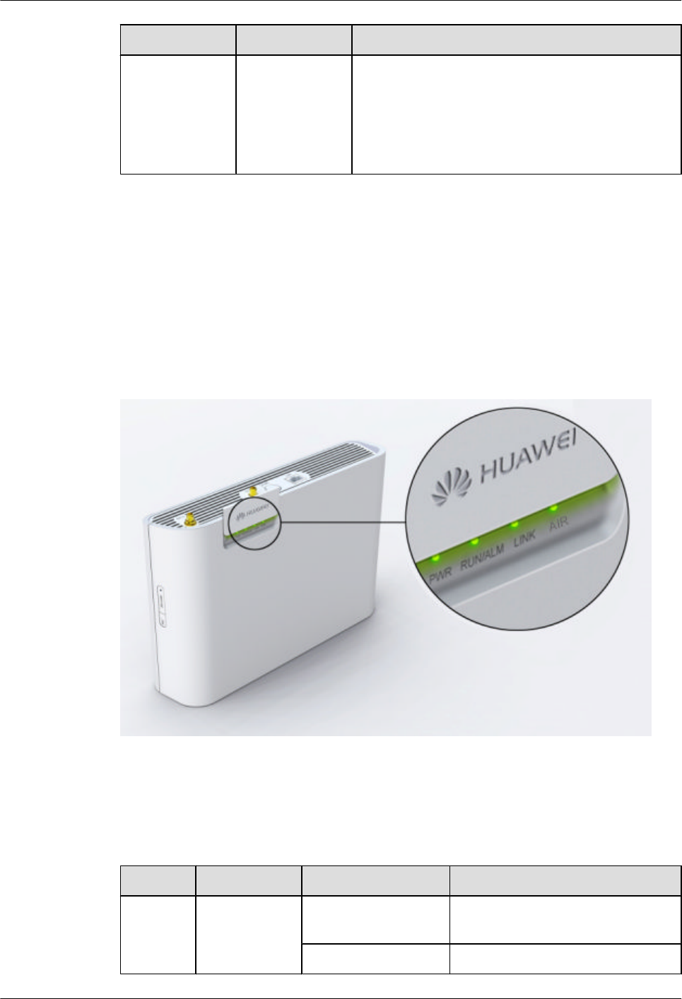
LEDs of the ePico3801
The ePico3801 has four LEDs, which show the running status of the ePico3801 through different
colors and blinking frequencies.
The four LEDs are located on the front panel of the ePico3801. After sliding open the cover in
the upper left corner of the front panel, you can see the four LEDs, as shown in Figure 2-4.
Figure 2-4 LEDs of the ePico3801
Table 2-2 describes the status of the LEDs of the ePico3801.
Table 2-2 Status of the LEDs of the ePico3801
LED Function Color/Status Meaning
PWR This LED
indicates the
power status.
Off and green There is no power supply, or the
power supply is faulty.
On and green The power supply is normal.
2 Introduction to the ePico3801
ePico3801
User Guide
2-8 Huawei Proprietary and Confidential
Copyright © Huawei Technologies Co., Ltd.
Issue 01 (2009–09–23)

LED Function Color/Status Meaning
RUN/
ALM
This LED
indicates the
running status.
Green and blinking
(on for 1s and off for
1s)
A cell is already established and can
provide services. The device is
working properly.
Green and blinking
(on for 0.125s and off
for 0.125s)
The device is in the startup loading
phase, or a software upgrade is in
progress.
Red and blinking (on
for 1s and off for 1s)
Critical alarms that affect services
are generated.
Red and blinking (on
for 0.125s and off for
0.125s)
The cell is unavailable.
On and red The device is severely faulty and
therefore needs to be repaired or
replaced.
AIR This LED
indicates the
status of the Uu
interface.
On and green There is no interference, and the
device is working properly. The GPS
signal is properly received.
Green and blinking
(on for 1s and off for
1s)
The device is working properly, and
users are using services.
On and red There is no GPS signal.
Red and blinking (on
for 1s and off for 1s)
The signal is exposed to slight
interference. The device can work,
but the communication quality is
degraded.
Red and blinking (on
for 0.125s and off for
0.125s)
The signal is exposed to severe
interference, and therefore the device
cannot work.
LINK This LED
indicates the
connectivity of
the Ethernet
port.
Off and green The Ethernet port is not properly
connected.
On and green The Ethernet port is properly
connected.
Green and blinking IP packets are being transmitted or
received through the Ethernet port.
2.3.2 Power Adapter
The ePico3801 can use the AC power supply or power supply from the PoE function. When the
AC power supply is used, the PoE power supply system is shut down automatically. When the
AC power supply is used, the ePico3801 needs to be configured with the AC/DC power adapter.
ePico3801
User Guide 2 Introduction to the ePico3801
Issue 01 (2009–09–23) Huawei Proprietary and Confidential
Copyright © Huawei Technologies Co., Ltd.
2-9
When the PoE power supply is used, the ePico3801 needs to be configured with the power supply
equipment (PSE).
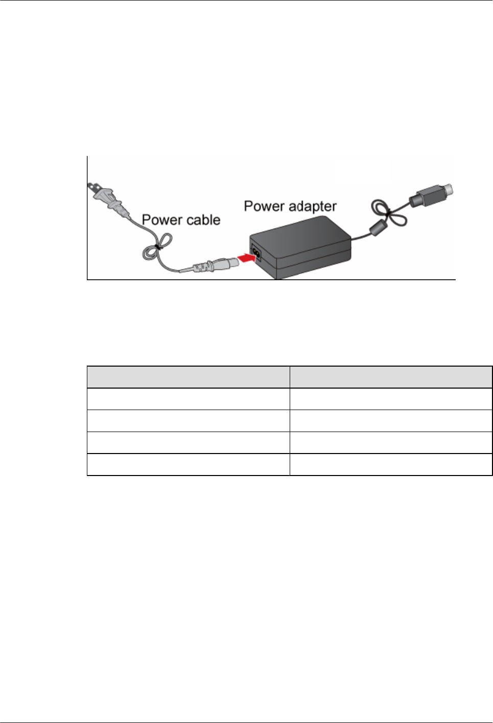
AC Power Supply
When the AC power supply is used, the ePico3801 needs to be configured with the AC/DC
power adapter, which converts the 110/220 V AC power supply to the 12 V DC power supply,
used by the ePico3801 as its working power supply. Figure 2-5 shows the AC/DC power adapter.
Figure 2-5 AC/DC power adapter
Table 2-3 describes the specifications and parameters of the AC/DC power adapter.
Table 2-3 Specifications and parameters of the AC/DC power adapter
Item Specification
Input voltage 110/220 V AC (90 V AC to 264 V AC)
Frequency of the input voltage 47 Hz to 63 Hz
Output voltage 12 V DC (11.4 V DC to 12.6 V DC)
Output current ≤ 2.9 A
PoE Power Supply
When the PoE power supply is used, the ePico3801 needs to be configured with the PSE, which
powers the ePico3801 through the Ethernet cable. In this case, the AC/DC power adapter is not
required. Figure 2-6 shows the PSE.
2 Introduction to the ePico3801
ePico3801
User Guide
2-10 Huawei Proprietary and Confidential
Copyright © Huawei Technologies Co., Ltd.
Issue 01 (2009–09–23)

Figure 2-6 PSE
Table 2-4 describes the ports on the PSE.
Table 2-4 Ports on the PSE
Port Silkscreen Description
Power supply port - Used for power input of the
PSE
Data input port DATA Connected to the
transmission device of the
user
PoE output port PoE Connected to the ePico3801
Table 2-5 describes the LEDs on the PSE.
Table 2-5 LEDs on the PSE
LED Color and Status Description
AC On and green The power supply is normal.
Off There is no power input, or
the PSE is faulty.
ePico3801
User Guide 2 Introduction to the ePico3801
Issue 01 (2009–09–23) Huawei Proprietary and Confidential
Copyright © Huawei Technologies Co., Ltd.
2-11

LED Color and Status Description
PORT On and green The PSE is properly
connected to the ePico3801.
Off The connection between the
PSE and the ePico3801 is
faulty, or the PSE is faulty.
Table 2-6 describes the specifications and parameters of the PSE.
Table 2-6 Specifications and parameters of the PSE
Item Specification
Input voltage 110/220 V AC (90 V AC to 264 V AC)
Frequency range 47 Hz to 63 Hz
Output voltage -54 V DC (-52 V DC to -56 V DC)
Output current ≤ 650 mA
2.4 Specifications of the ePico3801
The specifications of the ePico3801 involve its performance specifications, physical and
electrical specifications.
2.4.1 Performance Specifications
The performance specifications of the ePico3801 involve its RF performance, capacity, transmit
power, and service capabilities.
2.4.2 Physical and Electrical specifications
The physical and electrical specifications of the ePico3801 are its physical specifications, power
consumption specifications, and environmental specifications.
2.4.1 Performance Specifications
The performance specifications of the ePico3801 involve its RF performance, capacity, transmit
power, and service capabilities.
RF Specifications
Table 2-7 RF specifications of the ePico3801
Item Specification
Frequency bands Frequency band RX band (MHz) TX band (MHz)
BAND I (2100 MHz) 1920 to 1980 2110 to 2170
2 Introduction to the ePico3801
ePico3801
User Guide
2-12 Huawei Proprietary and Confidential
Copyright © Huawei Technologies Co., Ltd.
Issue 01 (2009–09–23)

Item Specification
Band II (1900 MHz) 1850 to 1910 1930 to 1990
Band V (850 MHz) 824 to 849 869 to 894
Capacity One carrier, one cell
TX power In band I, the TX power is 100 mW (20 dBm). In band II and band
V, the TX power is 250 mW (24 dBm).
Diversity No transmit diversity or receive diversity
Receiver sensitivity -110.0 dBm
Clock accuracy ±0.1 ppm after locking
NOTE
The ePico3801 model whose output power is 250 mW supports band II and band V only, and the ePico3801
model whose output power is 100 mW supports band I only. The RF board that supports band I and the
RF board that supports band II and band V have different TX powers. Band II and band V are supported
by the same RF board, which can be configured to support either band II or band V based on the actual
situation.
Service Capabilities
Table 2-8 Service capabilities of the ePico3801
Item Specification
Ordinary PS and CS services Supporting a maximum of 32 concurrent
UEs
Supporting a maximum of 32 concurrent
UEs that use CS services
Supporting a maximum of 16 concurrent
UEs that use PS services
The service combination of a single user can
be made up of a maximum of one CS service
and three PS services.
HSPA The maximum rate in HSDPA is 7.2 Mbit/s.
The maximum rate in HSUPA is 1.44 Mbit/
s.
Supporting a maximum of 8 concurrent UEs
that use HSPA services
Supporting concurrent 3GPP R99/R4/R5/R6
services
ePico3801
User Guide 2 Introduction to the ePico3801
Issue 01 (2009–09–23) Huawei Proprietary and Confidential
Copyright © Huawei Technologies Co., Ltd.
2-13

Item Specification
UE mobility Supporting the processes of addition,
removal, and replacement in soft handovers
that comply with the Uu interface protocols
of 3GPP, thereby ensuring the mobility of
UEs
Supporting static relocation that complies
with the Uu interface protocol of 3GPP
Supporting reselection and handovers
between ePico cells, between ePico cells and
UMTS macro cells, and between ePico cells
and inter-RAT cells.
Supporting redirection to inter-RAT and
inter-frequency cells for UEs that exceed the
specifications
Supporting access handovers for PS and VP
UEs that exceed the specifications
NOTE
lUsers that have only CS services are known as CS users. Users that have PS services are known as PS
users. PS users can also have CS services.
lAmong the three PS services in the maximum service combination of a single user, one service is
carried by IMS.
2.4.2 Physical and Electrical specifications
The physical and electrical specifications of the ePico3801 are its physical specifications, power
consumption specifications, and environmental specifications.
Physical Specifications
Table 2-9 Physical specifications of the ePico3801
Item Specification
Dimensions (length x width x height) 250 mm x 60 mm x 175 mm
Weight ≤ 2 kg
Volume ≤ 2.5 L
Transmission port One FE port
Protection rate IP30
Mean Time Between Failures 88,861 hours
2 Introduction to the ePico3801
ePico3801
User Guide
2-14 Huawei Proprietary and Confidential
Copyright © Huawei Technologies Co., Ltd.
Issue 01 (2009–09–23)

Power Consumption Specifications
Table 2-10 Power Consumption Specifications of the ePico3801
Item Specification
The TX power is 100 mW
(20 dBm).
AC/DC power adapter ≤ 28W
PoE power supply ≤ 30W
The TX power is 250 mW
(24 dBm).
AC/DC power adapter ≤ 32W
PoE power supply ≤ 35W
Environmental Specifications
Table 2-11 Environmental specifications of the ePico3801
Item Specification
Temperature Operating temperature: -5°C to +40°C
Storage temperature:-40°C to +70°C
Relative humidity Relative humidity of the operating
environment: 5% RH to 95% RH
Relative humidity of the storage
environment: 5% RH to 95% RH
Altitude -60 m to +4000 m
Air pressure 70 kPa to 106 kPa
2.5 Application Scenarios
The ePico3801 is widely used for indoor coverage in small and medium enterprises (SMEs),
SOHOs, schools, and office buildings and for hot-spot indoor coverage at pubs, airports, stores,
and hotels.
2.5.1 Access Networking Scenarios
The ePico3801 is connected to an enterprise LAN or modem, which connects the ePico3801 to
the public IP network. Then, the public IP network connects the ePico3801 to the AG, and the
AG connects the ePico3801 to the UMTS core network. Through convergence and UMTS traffic
and signaling forwarding performed by the AG, routing towards the UMTS core network is
achieved. The ePico3801 can be connected to the public IP network in LAN access mode or
modem access mode.
2.5.2 Installation Scenarios
If installed in a factory or office building, the ePico3801 does not require a private equipment
room.
ePico3801
User Guide 2 Introduction to the ePico3801
Issue 01 (2009–09–23) Huawei Proprietary and Confidential
Copyright © Huawei Technologies Co., Ltd.
2-15
2.5.3 Typical Application Scenarios
The ePico3801 is designed to solve the indoor coverage problem of the UMTS network. With
the ePico3801, mobile operators can deploy ordinary indoor coverage, intensive coverage in
office buildings, and hot-spot indoor coverage quickly at low cost.
2.5.1 Access Networking Scenarios
The ePico3801 is connected to an enterprise LAN or modem, which connects the ePico3801 to
the public IP network. Then, the public IP network connects the ePico3801 to the AG, and the
AG connects the ePico3801 to the UMTS core network. Through convergence and UMTS traffic
and signaling forwarding performed by the AG, routing towards the UMTS core network is
achieved. The ePico3801 can be connected to the public IP network in LAN access mode or
modem access mode.
Modem Access
The ePico3801 can be connected the public IP network through a fixed phone modem or cable
TV cable.
Principle of Modem Access
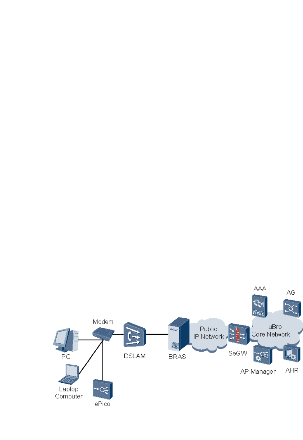
Each ePico3801 is connected to the public IP network through a modem. The digital subscriber
line access multiplexer (DSLAM) performs data convergence and distribution and isolates the
ePico3801 from other ePico3801s through a private VLAN. The service data is sent to the
broadband access server (BRAS) in Point-to-Point Protocol over Ethernet (PPPoE) or Dynamic
Host Configuration Protocol (DHCP) mode, and the BRAS performs access authentication and
billing for the public IP network. After the authentication is successful, the service data is sent
to the SeGW on the core network of the uBro solution through the public IP network. The SeGW
processes the data and forwards it to the AG and AAA. Figure 2-7 shows the networking in
modem access mode.
Figure 2-7 Networking in modem access mode
2 Introduction to the ePico3801
ePico3801
User Guide
2-16 Huawei Proprietary and Confidential
Copyright © Huawei Technologies Co., Ltd.
Issue 01 (2009–09–23)
Access Authentication
In modem access networking, access authentication and billing for the ePico3801 can be
performed in one of the following three modes, depending on mobile operators' policies:
lPPPoE dial-up mode
lStatic IP address mode
lDHCP mode
LAN Access
The ePico3801 can be directly connected to the public IP network through a LAN.
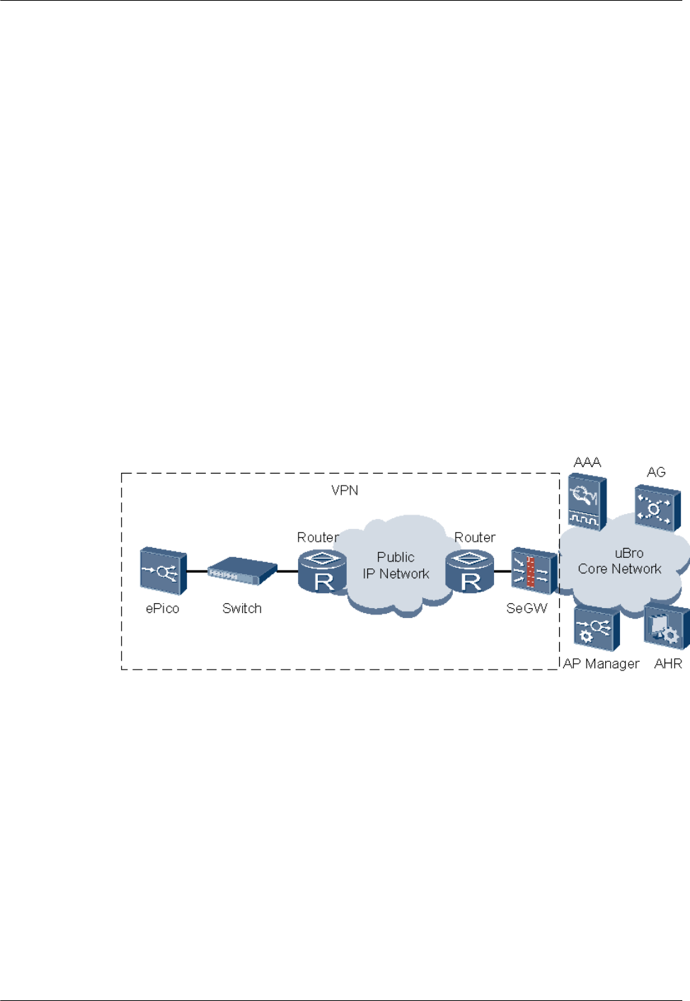
Principle of LAN Access
Each ePico3801 is directly connected to a switch or router through the enterprise LAN, which
connects the ePico3801 to the public IP network and isolates the ePico3801 from other
ePico3801s through a private VLAN. After the router performs Network Address Translation
(NAT) for the service data, the service data is sent to the SeGW on the core network of the uBro
solution through the public IP network. The SeGW processes the data and forwards it to the AG
and AAA. Figure 2-8 shows the networking in LAN access mode.
Figure 2-8 Networking in LAN access mode
Access Authentication
Like modem access networking, LAN access networking also supports access authentication in
PPPoE dial-up mode, static IP address mode, and DHCP mode.
2.5.2 Installation Scenarios
If installed in a factory or office building, the ePico3801 does not require a private equipment
room.
The ePico3801 is impact in structure and does not generate any noise. It can be easily installed
on a ceiling, wall, or pole depending on the actual requirements, preferences, and situations. The
installation process does not interfere with users' study or work. Figure 2-9 shows the typical
installation scenarios of the ePico3801.
ePico3801
User Guide 2 Introduction to the ePico3801
Issue 01 (2009–09–23) Huawei Proprietary and Confidential
Copyright © Huawei Technologies Co., Ltd.
2-17

Figure 2-9 Typical installation scenarios of the ePico3801
2.5.3 Typical Application Scenarios
The ePico3801 is designed to solve the indoor coverage problem of the UMTS network. With
the ePico3801, mobile operators can deploy ordinary indoor coverage, intensive coverage in
office buildings, and hot-spot indoor coverage quickly at low cost.
The ePico3801 has a good performance in terms of eliminating dead zones on the UMTS
network, implementing hot-spot indoor coverage, and providing small-scale private network
coverage. Typically, the ePico3801 provides small-scale private network coverage or hot-spot
indoor coverage for users in SMEs. Figure 2-10 shows the application of the ePico3801 in an
SME.
2 Introduction to the ePico3801
ePico3801
User Guide
2-18 Huawei Proprietary and Confidential
Copyright © Huawei Technologies Co., Ltd.
Issue 01 (2009–09–23)

Figure 2-10 Application of the ePico3801 in an SME
ePico3801
User Guide 2 Introduction to the ePico3801
Issue 01 (2009–09–23) Huawei Proprietary and Confidential
Copyright © Huawei Technologies Co., Ltd.
2-19

3 ePico3801 Initial Configuration
About This Chapter
This chapter describes how to perform initial configuration of the ePico3801 on the WebUI so
that users can perform the configuration of the ePico3801 according to the access and
authentication mode.
Prerequisite
The ePico3801 has been installed and powered on.
Context
The ePico3801 can access the network through the following authentication modes: PPPoE dial-
up, static IP address, and DHCP. For details, see 2.5.1 Access Networking Scenarios. By
default, the ePico3801 supports the DHCP authentication mode. The initial configuration is not
required. If you need to use the PPPoE dial-up or static IP authentication mode, initial
configuration is required.
3.1 Logging in to the ePico WebUI
This describes how to log in to the WebUI. For details about how to log in to the AP Manager,
see the AP Manager Operator Guide.
3.2 Configuring the ePico3801
This chapter describes how to configure the ePico3801 on the WebUI when the ePico3801
accesses the network through the PPPoE dial-up or static IP address authentication mode.
ePico3801
User Guide 3 ePico3801 Initial Configuration
Issue 01 (2009–09–23) Huawei Proprietary and Confidential
Copyright © Huawei Technologies Co., Ltd.
3-1

3.1 Logging in to the ePico WebUI
This describes how to log in to the WebUI. For details about how to log in to the AP Manager,
see the AP Manager Operator Guide.
Prerequisite
lThe ePico is powered on.
lThe version of the web browser on the PC meets the requirement.
the Internet Explorer (IE) must be version 6.0 or later versions; When logging in to the
WebUI through the Internet Explorer 8.0, certain manual configuration is needed, Choose
Tools > Compatibility View Settings, In the Compatibility View Settings dialog box,
Choose Display all websites in Compatibility View, Click Close.
lThe web browser does not use a proxy server.
To check whether the web browser uses a proxy server, perform the following steps where
IE 6.0 is taken as an example:
1. Open the IE. Choose Tools > Internet Options. The Internet Options dialog box
is displayed.
2. In the Internet Options dialog box, click the Connections tab. Then, click LAN
Settings.
3. In the Proxy server area, ensure that the check box Use a proxy server for your
LAN is not selected. Then, click OK.
Procedure
Step 1 Allocate an IP address for the computer. The IP address must be on the same network segment
as the IP address of the ePico.
NOTE
The default IP address of the ePico is 172.16.1.1, and the subnet mask is 255.255.255.0. To modify the
default IP address, do as follows:
1. Type http://172.16.1.1 in the address box of the web browser. Then, press Enter. The login dialog box
of the WebUI is displayed.
2. Click configuration.
3. Click TARGET IP in the left pane.
4. Click Mod.
5. Under Input Parameter Values, type the new IP address and the subnet mask. Then, click Done.
6. A message is displayed indicating that the change is successful. Exit the WebUI, and then log in to the
WebUI again by using the new IP address.
Step 2 Type the IP address of the ePico in the address box of the web browser. Then, press Enter. The
login dialog box of the WebUI is displayed, as shown in Figure 3-1.
3 ePico3801 Initial Configuration
ePico3801
User Guide
3-2 Huawei Proprietary and Confidential
Copyright © Huawei Technologies Co., Ltd.
Issue 01 (2009–09–23)
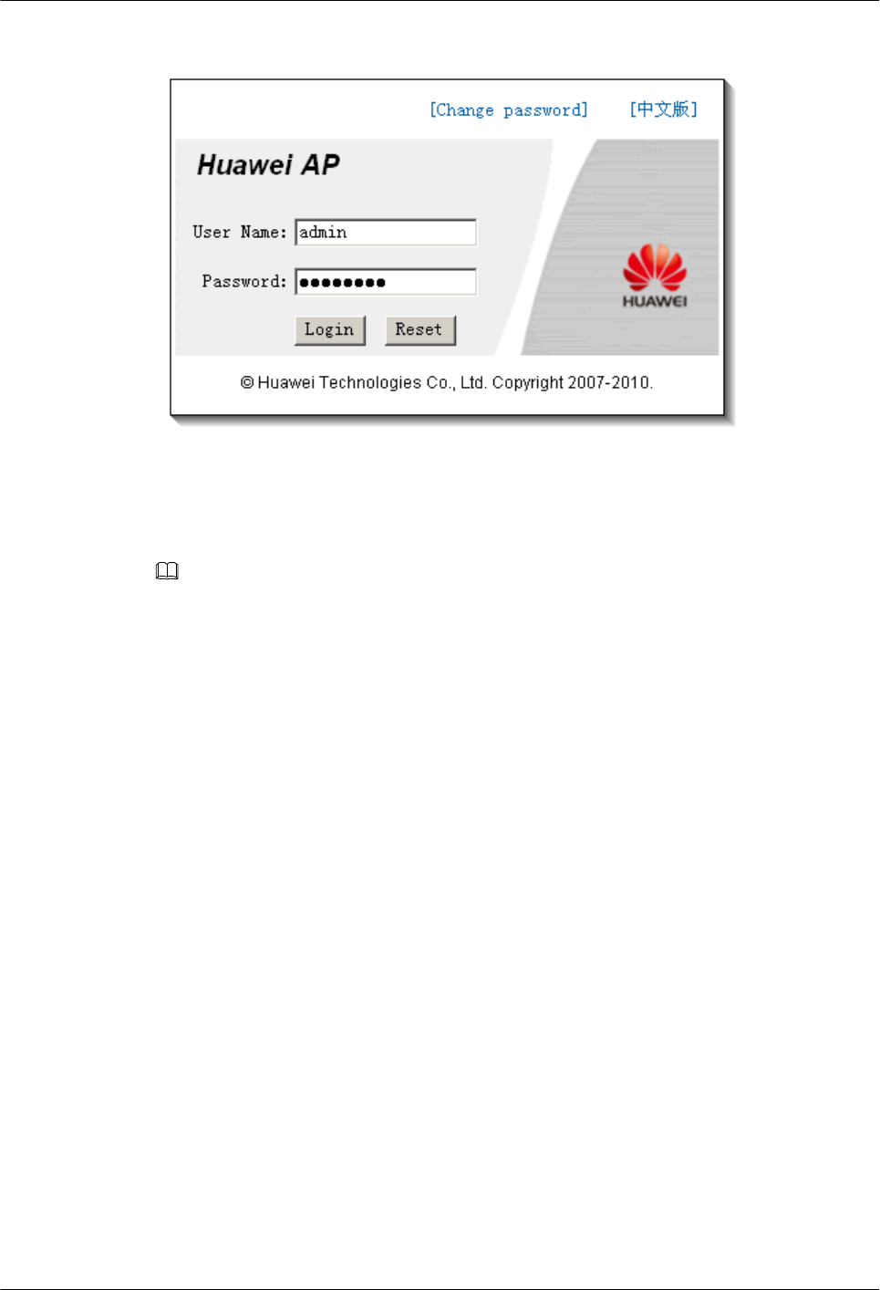
Figure 3-1 Logging in to the WebUI
Step 3 In the dialog box, type the user name and password under User Name and Password
respectively. Then, click Login.
NOTE
The user name is set to admin and cannot be changed. The default password is the last eight digits of the
APEI. The APEI is silk screened on the housing of the ePico. The system automatically prompts you to
change your password during the initial login. You must change your password before logging in to the
system normally.
If you fail to log in to the system after the maximum number of consecutive login failures (three times by
default) within the specified time (five minutes by default), the system is blocked for six hours by default.
You can unblock the account after the duration times out or press the RST button to reset the system. If
the duration of system unblocking is set to 0 on the AP Manager, it indicates that you must reset the ePico
for re-login when your account is locked.
Click Change password to change your password, The new password must meet the following conditions:
lThe new password must consists of 8 to 18 characters.
lThe new password cannot contain 3 or more consecutive same characters.
lThe new password must contain at least 3 combinations of a lower-case letter, upper-case letter, number,
and special character (such as ~!@#$%^*()-_=+\|[{}];:'",.>/?, and space).
----End
3.2 Configuring the ePico3801
This chapter describes how to configure the ePico3801 on the WebUI when the ePico3801
accesses the network through the PPPoE dial-up or static IP address authentication mode.
Prerequisite
3.1 Logging in to the ePico WebUI is complete.
ePico3801
User Guide 3 ePico3801 Initial Configuration
Issue 01 (2009–09–23) Huawei Proprietary and Confidential
Copyright © Huawei Technologies Co., Ltd.
3-3

Procedure
lThe ePico3801 accesses the network through the PPPoE dial-up authentication mode.
1. In the WebUI home page, choose Transfer Basic > ETHIP, and then click Del.
2. Choose PPPOELINK and click Add. Then, enter the username and password for the
PPPoE dial-up connection and click Done.
3. The ePico3801 restarts automatically to validate the new configuration.
lThe ePico3801 accesses the network through the static IP address to be authenticated.
1. In the WebUI home page, choose Transfer Basic > ETHIP, and then click Mod.
2. Change the value of Auto IP to DISABLE and enter the required static IP address,
net mask, and gateway IP address. Then, click Done.
3. The ePico3801 restarts automatically to validate the new configuration.
----End
Postrequisite
After the initial configuration, the following items must be confirmed:
lThe corresponding ePico zone has been activated.
lThe ePico3801 has registered in the corresponding zone.
lThe network planning parameters of the ePico3801 have been set.
3 ePico3801 Initial Configuration
ePico3801
User Guide
3-4 Huawei Proprietary and Confidential
Copyright © Huawei Technologies Co., Ltd.
Issue 01 (2009–09–23)

4 Commissioning the ePico3801
About This Chapter
This chapter describes the commissioning and verification after the installation of the ePico3801
hardware. The commissioning ensures that the ePico3801 works properly as designed.
4.1 Commissioning Procedure
This chapter describes the prerequisites, required resources, and procedure of the ePico3801
commissioning.
4.2 Checking the Hardware Status
This chapter describes how to check the status of the ePico3801 hardware.
4.3 Checking the Network Transmission
This chapter describes how to check the network transmission of the ePico3801 to ensure that
the ePico3801 communicates with other NEs properly.
4.4 Checking the Software Version
This chapter describes how to check the software version of the ePico3801.
4.5 Checking the Running Status
This chapter describes how to check the running status of the ePico3801.
4.6 Testing Services
This chapter describes how to test the services provided by the ePico3801 to ensure that the
ePico3801 can provide basic telecommunication services such as CS and PS services.
4.7 Data Sheet for Commissioning
This chapter provides the data sheet that is used to record the process and result of the
commissioning.
4.8 Communication Ports on the ePico3801
ePico3801
User Guide 4 Commissioning the ePico3801
Issue 01 (2009–09–23) Huawei Proprietary and Confidential
Copyright © Huawei Technologies Co., Ltd.
4-1

4.1 Commissioning Procedure
This chapter describes the prerequisites, required resources, and procedure of the ePico3801
commissioning.
Prerequisite
lThe NEs including the SeGW, AAA, APM, AHR, IP clock, and AG involved in the uBro
solution are running properly. The network transmission is normal.
lThe initial configuration of the ePico3801 is complete.
Commissioning Resources
Table 4-1 describes the tools required for ePico3801 commissioning.
Table 4-1 Tools for ePico3801 commissioning
Tool Quantity Description
PC 1 Log in to ePico local
maintenance IP address
through a PC to perform local
commissioning, or log in to
the AP Manager (APM) to
perform commissioning.
UE 2 Use the UEs to make call tests
on ePico3801 services.
Fixed-line telephone 1 Use the fixed-line telephone
to make call tests on
ePico3801 services.
The following basic information must be obtained before the commissioning.
lThe networking mode and transmission mode of the ePico3801 are available.
lThe required software version and basic configuration data of the ePico3801 are available.
Commissioning Procedures
Figure 4-1 shows the procedures for commissioning the ePico3801.
4 Commissioning the ePico3801
ePico3801
User Guide
4-2 Huawei Proprietary and Confidential
Copyright © Huawei Technologies Co., Ltd.
Issue 01 (2009–09–23)
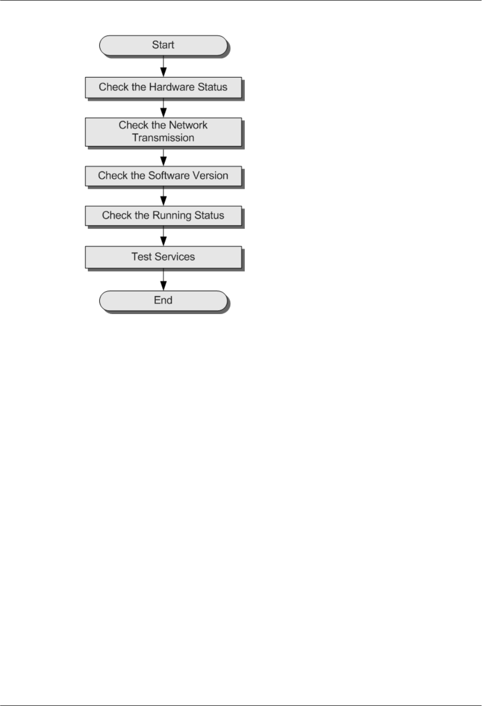
Figure 4-1 Commissioning procedures
Procedure
Step 1 4.2 Checking the Hardware Status.
Step 2 Check the network transmission status between the ePico3801 and the SeGW, AG, and APM.
For details, see 4.3 Checking the Network Transmission.
Step 3 4.4 Checking the Software Version.
Step 4 4.5 Checking the Running Status.
Step 5 Use the UEs to test the services provided by the ePico. For details, see 4.6 Testing Services.
----End
4.2 Checking the Hardware Status
This chapter describes how to check the status of the ePico3801 hardware.
Procedure
Step 1 Check the LEDs on the equipment.
If the LEDs on the ePico3801 are in the state described in Table 4-2, it indicates that the
equipment is functioning properly.
ePico3801
User Guide 4 Commissioning the ePico3801
Issue 01 (2009–09–23) Huawei Proprietary and Confidential
Copyright © Huawei Technologies Co., Ltd.
4-3

Table 4-2 Normal status of the LEDs
LED State
PWR ON (green)
RUN/ALM Blinking green (ON for 1s and OFF for 1s)
AIR ON or blinking (green)
LINK ON or blinking (green)
Step 2 If the LEDs on the equipment are in abnormal state, troubleshoot the problem by referring to
Table 4-3.
Table 4-3 Abnormal status of the LEDs
LED State Description Handling Method
PWR OFF (green) No power supply is available
or the power supply is
improper.
Check whether the power
ports are connected properly
and whether the power
supply system is faulty.
RUN/
ALM
Blinking green
(ON for 0.125s
and OFF for
0.125s)
The equipment is in the
phase of starting and loading
or the software of the
equipment is being
upgraded.
Wait for five minutes and
then check the status of the
RUN/ALM LED again.
If the RUN/ALM LED still
blinks four times every
second, record the problem
in the commissioning table
for the analysis through the
AP Manager (APM).
Blinking red
(ON for 1s and
OFF for 1s)
A critical alarm is reported,
which affects the services.
The ePico3801 cannot
provide services.
Record the problem in the
commissioning table for the
analysis through the APM.
Blinking red
(ON for 0.125s
and OFF for
0.125s)
The cell cannot provide
services.
4.3 Checking the Network
Transmission, and then
check the status of the LEDs
again.
If the RUN/ALM LED is still
constantly ON, record the
problem in the
commissioning table for the
analysis through the APM.
ON (red) The equipment is faulty and
needs to be maintained or
replaced.
Replace the equipment.
4 Commissioning the ePico3801
ePico3801
User Guide
4-4 Huawei Proprietary and Confidential
Copyright © Huawei Technologies Co., Ltd.
Issue 01 (2009–09–23)

LED State Description Handling Method
AIR ON (red) There is no GPS signal. lCheck the GPS antenna
connector. If the
connector is loose,
reinsert the connector and
fasten it.
lChange the position for
installing the GPS
antenna.
Blinking red
(ON for 1s and
OFF for 1s)
The signals of the ePico3801
are under slight interference.
The ePico3801 works
properly, but the
telecommunication quality
deteriorates.
lEliminate the interference
source around the
equipment.
lChange the position for
installing the ePico3801.
Blinking red
(ON for 0.125s
and OFF for
0.125s)
The signals of the ePico3801
are under strong
interference. The ePico3801
cannot work properly.
LINK OFF (green) The Ethernet port is
connected improperly.
Check whether the Ethernet
ports on the ePico3801 and
the peer equipment are faulty
and whether the Ethernet
cable is available.
----End
4.3 Checking the Network Transmission
This chapter describes how to check the network transmission of the ePico3801 to ensure that
the ePico3801 communicates with other NEs properly.
Prerequisite
The ePico3801 hardware is checked and in normal status.
Procedure
Step 1 Check the RUN/ALM LED.
If the RUN/ALM LED Is... Then...
Blinking green (ON for 1s and OFF for 1s) The network transmission is normal. End the
check.
Other status Go to Step 2.
ePico3801
User Guide 4 Commissioning the ePico3801
Issue 01 (2009–09–23) Huawei Proprietary and Confidential
Copyright © Huawei Technologies Co., Ltd.
4-5

Step 2 3.1 Logging in to the ePico WebUI. In the Execute Trouble Diagnose window, select Transfer
Trouble Diagnose and select Show All Result. Then, click Start to start checking the
transmission status of the ePico3801.
Step 3 Check the statistical information SCTP State, SecGW LINK, APM LINK, and TSP Current
State and ensure that the transmission between the ePico3801 and the NEs is normal.
1. Check the SecGW LINK status.
If... Description Then...
The test results of SecGW
LINK are as follows:
4 packet(s) transmitted
4 packet(s) received
Percent 0.00 packet lost
round-trip min/avg/max =
1/3/10 ms
The network
transmission
between the
ePico3801 and the
SecGW is normal.
Go to Step 3.2.
The test result of SecGW
LINK is Invalid or TimeOut
The communication
between the
ePico3801 and the
SecGW fails.
lCheck whether the IP address
of the firewall configured on
the ePico is correct.
lCheck whether the firewall
works normally.
2. Check the SCTP State status.
If... Description Then...
The SCTP State status
is OK
The SCTP link is
established.
Go to Step 3.3.
The SCTP State status
is NOK
The SCTP link is
not established.
The
communication
between the ePico
and AG fails.
Ensure that the IPsec tunnel between the
ePico3801 and the firewall is
established successfully.
3. Check the APM LINK status.
If... Description Then...
The test results of APM
LINK are as follows:
4 packet(s) transmitted
4 packet(s) received
Percent 0.00 packet lost
round-trip min/avg/
max = 1/3/10 ms
The network
transmission
between the
ePico3801 and the
APM is normal.
Go to Step 3.4.
4 Commissioning the ePico3801
ePico3801
User Guide
4-6 Huawei Proprietary and Confidential
Copyright © Huawei Technologies Co., Ltd.
Issue 01 (2009–09–23)

If... Description Then...
The test result of APM
LINK is Invalid or
TimeOut
The
communication
between the
ePico3801 and the
APM fails.
lEnsure that the transmission between
the ePico and the firewall and
between the firewall and the APM is
normal.
lEnsure that the APM is installed with
the current version of the ePico3801.
lEnsure that the IPsec tunnel between
the ePico and the firewall is
established successfully.
4. Check the TSP Current State status.
If... Description Then...
The TSP State status is
TransOK
The network
transmission is
normal.
End the check.
The TSP Current
State status is NOK
The network
transmission is
faulty.
Rectify the fault according to the
displayed fault cause of TSP Current
State.
NOTE
If the fault persists, contact the Huawei technical support engineers.
----End
4.4 Checking the Software Version
This chapter describes how to check the software version of the ePico3801.
Prerequisite
lThe network transmission between the ePico3801 and the AP Manager (APM) is normal.
lThe ePico3801 hardware is normal.
lYou have logged in to the WebUI through a computer.
Procedure
lLog in to the WebUI to check the software version of the equipment.
The software version is directly displayed in the upper right of the WebUI window.
lLog in to the APM to check the software version of the equipment.
Choose Configuration > Single Configuration. In the Terminal Search area, enter the
relevant information of the equipment, and then click Search. The query result is displayed
in the Terminal List area.
----End
ePico3801
User Guide 4 Commissioning the ePico3801
Issue 01 (2009–09–23) Huawei Proprietary and Confidential
Copyright © Huawei Technologies Co., Ltd.
4-7

Postrequisite
If the software version of the equipment is incorrect, upgrade the software version by referring
to the APM Operator Guide.
4.5 Checking the Running Status
This chapter describes how to check the running status of the ePico3801.
Prerequisite
The ePico3801 hardware is in normal state, the transmission is available, and the running
software version is correct.
Procedure
Step 1 Check the equipment alarm on the AP Manager (APM) and clear the existing alarm by referring
to the APM Operator Guide.
If... Then...
An alarm is generated Clear the alarm according to Help.
An active alarm cannot
be cleared
Record the alarm in the 4.7 Data Sheet for Commissioning.
----End
4.6 Testing Services
This chapter describes how to test the services provided by the ePico3801 to ensure that the
ePico3801 can provide basic telecommunication services such as CS and PS services.
Prerequisite
lThe ePico cell is set up.
lTwo functional UEs (UE 1 and UE 2) are ready.
lThe IMSIs of UE 1 and UE 2 are added to the ePico permission list.
lA functional fixed-line phone is ready.
lThe CS and PS domains in the core network are functional.
Testing Items
Table 4-4 describes the basic items in the ePico3801 service test.
4 Commissioning the ePico3801
ePico3801
User Guide
4-8 Huawei Proprietary and Confidential
Copyright © Huawei Technologies Co., Ltd.
Issue 01 (2009–09–23)

Table 4-4 Basic items in the service test
Testing Items Method Expected Result
Test voice call services. UE 1 or UE 2 originates a voice
call to a fixed-line phone.
The voice quality is good, and
there is no loud noise.
UE 1 originates a voice call to
UE 2.
The voice quality is good, and
there is no loud noise.
Test video call services. UE 1 originates a video call to
UE 2.
lThe voice is clear.
lThe video is clear and
uninterrupted.
lThe voice is synchronized
with the video.
Test streaming video
services.
UE 1 performs the VOD
services.
lThe voice is clear.
lThe video is clear and
uninterrupted.
lThe voice is synchronized
with the video.
4.7 Data Sheet for Commissioning
This chapter provides the data sheet that is used to record the process and result of the
commissioning.
Table 4-5 Data sheet for commissioning
Site Name
Models
Commission Time
Commissioning
Engineer
Commissioning
Result
□ Successful;□ Failed
Commissioning Item Conclusion Handling
Exceptional Case
Commissioning
Preparation Phase
Faults in hardware installation
are rectified.
□ Yes; □ No
Negotiation data of the
ePico3801 to be commissioned
is added to the AP Manager
(APM).
□ Yes; □ No
ePico3801
User Guide 4 Commissioning the ePico3801
Issue 01 (2009–09–23) Huawei Proprietary and Confidential
Copyright © Huawei Technologies Co., Ltd.
4-9

Commissioning
Phase
The hardware status is checked. □ Yes; □ No
The network transmission
status is checked.
□ Yes; □ No
The software version is
checked.
□ Yes; □ No
The running status of the
ePico3801 is checked.
□ Yes; □ No
The basic services are tested. □ Yes; □ No
Description Impact
Unsolved Problems
After
Commissioning
Component P/N
Record of Faulty
Equipment
4.8 Communication Ports on the ePico3801
This chapter describes the communication ports on the ePico3801. Table 4-6 describes the
communication ports on the ePico3801.
Table 4-6 Communication ports on the ePico3801
Prot
ocol
A
Side
A
Side
Port
Num
ber
(RX)
B Side B Side
Port
Number
(TX)
Service Authority
Manageme
nt
TCP ePico
3801
80 IE
browser
1024-6553
5
WebUI port for local OM Username
and
password
TCP ePico
3801
6000 LMT 1024-6553
5
MML port for local OM Username
and
password
TCP ePico
3801
6006 LMT 1024-6553
5
Binary port for local OM Username
and
password
4 Commissioning the ePico3801
ePico3801
User Guide
4-10 Huawei Proprietary and Confidential
Copyright © Huawei Technologies Co., Ltd.
Issue 01 (2009–09–23)

Prot
ocol
A
Side
A
Side
Port
Num
ber
(RX)
B Side B Side
Port
Number
(TX)
Service Authority
Manageme
nt
TCP ePico
3801
7547 AP
Manager
1024-6553
5
TR-069 protocol port -
TCP ePico
3801
500 SeGW 1024-6553
5
Default IKE port of the
IPSec
-
TCP ePico
3801
4500 SeGW 1024-6553
5
NAT protocol port of the
IPSec
-
TCP ePico
3801
3300
3
CLK
Server
1024-6553
5
Clock synchronization -
ePico3801
User Guide 4 Commissioning the ePico3801
Issue 01 (2009–09–23) Huawei Proprietary and Confidential
Copyright © Huawei Technologies Co., Ltd.
4-11

5 Reconfiguring the ePico3801
About This Chapter
This chapter describes common reconfiguration items during the normal running of the
ePico3801.
5.1 Configuring Automatic Network Planning Parameters
This chapter describes how to configure the automatic network planning parameters for the
ePico3801 on the AP Manager (APM). For the deployment of most ePico3801s, the automatic
network planning mode ensures a good radio environment.
5.2 Setting ePico Cell Parameters
This chapter describes how to set or modify the ePico cell parameters manually. This mainly
introduces common configuration methods of the ePico cell parameters, including modifying
the cell status, modifying the cell frequency and scramble code, and setting the maximum TX
power.
5.3 Modifying Automatic Pilot Adjustment Parameters
This chapter describes how to modify the automatic pilot adjustment parameters. You need to
set the automatic pilot adjustment parameters for the ePico3801 to ensure that the interference
is effectively reduced and the voice quality meets the requirements. In normal cases, these
parameters need not be modified after the parameter setting is complete.
5.4 Adjusting Mobility Management Parameters
This chapter describes how to adjust the ePico3801 parameters related to the cell reselection and
handover if required. In normal cases, the information of the ePico cell is configured through
automatic network planning. No manual configuration is required.
5.5 Adjusting the Transport Network
This chapter describes how to adjust the transport network of the ePico3801.
5.6 Adjusting the ePico3801 Functions
This chapter describes how to adjust the application of the ePico3801 basic functions. The basic
functions consist of the HSPA status, emergency call redirection switch, permission reject
reason, location indication mode, differentiated billing mode, and location positioning mode.
ePico3801
User Guide 5 Reconfiguring the ePico3801
Issue 01 (2009–09–23) Huawei Proprietary and Confidential
Copyright © Huawei Technologies Co., Ltd.
5-1

5.1 Configuring Automatic Network Planning Parameters
This chapter describes how to configure the automatic network planning parameters for the
ePico3801 on the AP Manager (APM). For the deployment of most ePico3801s, the automatic
network planning mode ensures a good radio environment.
Prerequisite
lThe ePico zone has been activated on the APM.
lYou have logged in to the APM. The login account belongs to the Administrator or
Operators group.
lYou have obtained the frequency information planned for the ePico zone.
Context
The frequency list information configured by running the following commands is valid only if
the ePico3801 is in automatic network planning mode.
lAutomatic network planning: The frequencies, scrambling codes, and information about
neighboring cells are configured on the APM. After the ePico3801 is powered on and the
cell is set up, the APM automatically issues the configuration information to the
corresponding ePico3801. No manual configuration is required. By default, the factory
parameter setting mode of the ePico3801 is automatic network planning.
lManual network planning: Change the mode of configuring the frequency, scrambling
code, and information about neighboring cells to manual configuration. For details, see 5.2
Setting ePico Cell Parameters. You can change the configuration information of a cell as
required.
Procedure
Step 1 Log in to the APM. Choose Configuration > Zone Configuration and select an ePico zone to
be maintained. Then, click Configure.
Step 2 In the displayed window, select the correct version from the Version drop-down list, and then
click Next.
Step 3 Set the parameters of the ePico zone. Choose Zone Parameter > WIRELESS >
Configuration in the navigation tree to set the parameters of the ePico zone.
1. Choose APCELLFREQ to set the frequency list of the ePico cell.
NOTE
If the ePico cell is set up in automatic network planning mode, you need to configure the frequency
list of the ePico cell. After the configuration is complete, the ePico searches all the frequencies in
the frequency list to identify a frequency with the minimal interference for itself.
2. Choose APPSCODE to set the scramble code list of the ePico cell.
3. Choose MCELLFREQ to set the macro neighboring cell list of the ePico cell.
4. Choose GSMPLMNID to set the mobile network code (MNC) of 2G neighboring cells.
NOTE
For details about how to set the parameters, see Help in the corresponding command window.
5 Reconfiguring the ePico3801
ePico3801
User Guide
5-2 Huawei Proprietary and Confidential
Copyright © Huawei Technologies Co., Ltd.
Issue 01 (2009–09–23)

Step 4 After the parameter setting is complete, click Confirm and then click Submit. A system message
is displayed, indicating whether the parameter setting is successful.
----End
5.2 Setting ePico Cell Parameters
This chapter describes how to set or modify the ePico cell parameters manually. This mainly
introduces common configuration methods of the ePico cell parameters, including modifying
the cell status, modifying the cell frequency and scramble code, and setting the maximum TX
power.
Prerequisite
lThe parameters of the ePico zone have been set successfully.
lYou have logged in to the AP Manager (APM). The login account belongs to the
Administrator or Operators group.
Procedure
Step 1 Log in to the APM. Choose Configuration > Single Configuration and select an ePico3801 to
be maintained. Then, click Configure to enter the configuration window.
Step 2 Choose Terminal Parameter > WIRELESS > Configuration in the navigation tree to
configure the automatic pilot adjustment parameters.
1. Choose CELLSTATE to modify the cell active status. Before activating the data of a cell,
you need to ensure that the data of the cell is complete and valid.
2. Choose CELLBASIC to modify the basic information of the cell.
CAUTION
You can use this command to modify the AP frequency, scramble code, and neighboring
cell configuration mode after deactivating the cell. If the cell is in activated state, you cannot
modify the cell information directly.
3. Choose CELL to modify the basic information of the cell. You can use this command to
modify the basic information such as the maximum TX power of a cell, PSCH TX power,
SSCH TX power, PCPICHP TX power, BCH TX power, and downlink maximum TX
power of UEs in a cell.
4. Choose CELLRESETUPTIMER to set the timer for cell reestablishment. This command
is applicable to the automatic network planning mode. Before the timer for periodical cell
reestablishment expires, the cell performs network planning automatically again. In this
case, the ePico3801 automatically selects better parameters related to the network planning
to reestablish the cell according to the new radio environment so that the network quality
of the cell is optimized. If there are UEs in the cell when cell reestablishment time arrives,
the ePico3801 skips this cell reestablishment time and then reestablishes the cell when the
next cell reestablishment time arrives.
5. Choose MAXUEPOWERPARA to set the maximum allowed uplink TX power of a UE.
ePico3801
User Guide 5 Reconfiguring the ePico3801
Issue 01 (2009–09–23) Huawei Proprietary and Confidential
Copyright © Huawei Technologies Co., Ltd.
5-3

NOTE
If the maximum TX power of the UE is too low, the UE may not receive the AP signals, and thus
the UE cannot process services. If the maximum TX power is too high, the uplink interference of
other cells is generated.
NOTE
For details about how to set the parameters, see Help in the corresponding configuration window.
Step 3 After the parameter setting is complete, click Apply. A system message is displayed, indicating
whether the parameter setting is successful.
----End
5.3 Modifying Automatic Pilot Adjustment Parameters
This chapter describes how to modify the automatic pilot adjustment parameters. You need to
set the automatic pilot adjustment parameters for the ePico3801 to ensure that the interference
is effectively reduced and the voice quality meets the requirements. In normal cases, these
parameters need not be modified after the parameter setting is complete.
Prerequisite
lThe parameters of the ePico zone have been set successfully.
lYou have logged in to the AP Manager (APM). The login account belongs to the
Administrator or Operators group.
Context
ePico3801 supports two automatic pilot adjustment modes: fast automatic pilot adjustment based
on dialing and period automatic pilot adjustment based on measurement.
Procedure
Step 1 Log in to the APM. Choose Configuration > Single Configuration and select an ePico3801 to
be maintained. Then, click Configure to enter the configuration window.
Step 2 Choose Terminal Parameter > WIRELESS > Configuration in the navigation tree to
configure the automatic pilot adjustment parameters.
1. Choose PCPICHPWR to set the BCH transmit power from the PCPICH transmit power
(PCPICH).
2. Choose AUTOPOWER to set the automatic pilot adjustment algorithm based on calls.
3. Choose AUTOPOWERSTAT to set the automatic pilot adjustment algorithm based on
measurement.
4. Choose AUTOTESTNUM to set the automatic pilot test number of the ePico3801.
NOTE
For details about how to set the parameters, see Help in the corresponding configuration window.
Step 3 After the parameter setting is complete, click Apply. A system message is displayed, indicating
whether the parameter setting is successful.
----End
5 Reconfiguring the ePico3801
ePico3801
User Guide
5-4 Huawei Proprietary and Confidential
Copyright © Huawei Technologies Co., Ltd.
Issue 01 (2009–09–23)

5.4 Adjusting Mobility Management Parameters
This chapter describes how to adjust the ePico3801 parameters related to the cell reselection and
handover if required. In normal cases, the information of the ePico cell is configured through
automatic network planning. No manual configuration is required.
5.4.1 Modifying 3G Macro Neighboring Cells
This chapter describes how to manually add 3G macro neighboring cells on the AP Manager
(APM). This operation can be performed only in manual network planning mode.
5.4.2 Modifying 2G Macro Neighboring Cells
This chapter describes how to manually add 2G macro neighboring cells on the AP Manager
(APM). This operation can be performed only in manual network planning mode.
5.4.3 Modify HCS Reselection Parameters
This chapter describes how to modify the hierarchical cell structure (HCS) parameters of the
ePico3801. The ePico3801 supports the preferential camping-on mode of the HCS. You can
adjust the configuration to ensure that the ePico cell has a high priority. In this case, the UE
preferentially selects an ePico cell to camp on it. This requires that the HCS parameters are also
set in the macro network.
5.4.4 Modifying Signal Quality Offset Reselection Parameters
This chapter describes how to modify the signal quality offset reselection parameters. The ePico
supports the reselection camping-on mode based on the signal quality offset. You can adjust the
signal quality offset value of the ePico to ensure that the UE preferentially selects an ePico cell
to be a serving cell after comparing the signal quality of the macro cell with the signal quality
of the ePico cell.
5.4.5 Modifying the ePico3801 Parameters Related to the Handover to 3G Macro Cells
This chapter describes how to set the ePico3801 parameters manually to implement the handover
to the 3G macro cells or ePico cells. In normal cases, these parameters of the ePico3801 are set
automatically. No manual setting is required.
5.4.6 Modifying the ePico3801 Parameters Related to the Handover to 2G Macro Cells
This chapter describes how to modify the ePico3801 parameters manually to implement the
handover to the 2G macro cells. In normal cases, these parameters of the ePico3801 are set
automatically. No manual setting is required.
5.4.1 Modifying 3G Macro Neighboring Cells
This chapter describes how to manually add 3G macro neighboring cells on the AP Manager
(APM). This operation can be performed only in manual network planning mode.
Prerequisite
lThe parameters of the ePico zone have been set successfully.
lYou have logged in to the APM. The login account belongs to the Administrator or
Operators group.
Context
If the signal quality of a UE in an ePico cell is poor, the UE needs to be handed over to a 3G
inter-RAT neighboring cell. In this case, the information about 3G neighboring cells needs to
be configured.
ePico3801
User Guide 5 Reconfiguring the ePico3801
Issue 01 (2009–09–23) Huawei Proprietary and Confidential
Copyright © Huawei Technologies Co., Ltd.
5-5

NOTE
If the 2G inter-RAT neighboring cells also exist, however, the UE may be handed over to a 2G or 3G
neighboring cell. This is determined by the parameter setting. For details, see 5.4.5 Modifying the
ePico3801 Parameters Related to the Handover to 3G Macro Cells.
Procedure
Step 1 Log in to the APM. Choose Configuration > Single Configuration and select an ePico3801 to
be maintained. Then, click Configure to enter the configuration window.
Step 2 Choose Terminal Parameter > WIRELESS > Configuration in the navigation tree to
configure the 3G macro neighboring cell parameters.
1. Choose NRNC to set the information about the neighboring RNCs.
2. Choose NRNCCELL to add, delete, or modify the cells controlled by the neighboring
RNCs.
3. Choose INTERFREQNCELL to add, delete, or modify the inter-frequency neighboring
cells.
4. Choose INTRAFREQNCELL to add, delete, or modify the intra-frequency neighboring
cells.
NOTE
lThe commands in Step 2.2, Step 2.3, and Step 2.4 can be executed only after the information about
the neighboring RNCs is configured.
lFor details about how to set the parameters, see Help in the corresponding configuration window.
Step 3 After the parameter setting is complete, click Apply. A system message is displayed, indicating
whether the parameter setting is successful.
----End
5.4.2 Modifying 2G Macro Neighboring Cells
This chapter describes how to manually add 2G macro neighboring cells on the AP Manager
(APM). This operation can be performed only in manual network planning mode.
Prerequisite
lThe parameters of the ePico zone have been set successfully.
lYou have logged in to the APM. The login account belongs to the Administrator or
Operators group.
Context
If the signal quality of a UE in an AP cell is poor, the UE needs to be handed over to a 2G inter-
RAT neighboring cell. In this case, the information about 2G neighboring cells needs to be
configured. If both the 2G and 3G neighboring cells exist, the UE is handed over to a 3G
neighboring cell by default. If you require the UE to be handed over to a 2G neighboring cell,
you need to run the HOCOMM command in the APM window to change the related parameter
setting. For details, see 5.4.5 Modifying the ePico3801 Parameters Related to the Handover
to 3G Macro Cells.
5 Reconfiguring the ePico3801
ePico3801
User Guide
5-6 Huawei Proprietary and Confidential
Copyright © Huawei Technologies Co., Ltd.
Issue 01 (2009–09–23)

Procedure
Step 1 Log in to the APM. Choose Configuration > Single Configuration and select an ePico3801 to
be maintained. Then, click Configure to enter the configuration window.
Step 2 Choose Terminal Parameter > WIRELESS > Configuration in the navigation tree to
configure the automatic pilot adjustment parameters.
1. Choose GSMCELL to add the GSM neighboring cell information.
2. Choose GSMNCELL to configure the GSM neighboring cells.
NOTE
For details about how to set the parameters, see Help in the corresponding configuration window.
Step 3 After the parameter setting is complete, click Apply. A system message is displayed, indicating
whether the parameter setting is successful.
----End
5.4.3 Modify HCS Reselection Parameters
This chapter describes how to modify the hierarchical cell structure (HCS) parameters of the
ePico3801. The ePico3801 supports the preferential camping-on mode of the HCS. You can
adjust the configuration to ensure that the ePico cell has a high priority. In this case, the UE
preferentially selects an ePico cell to camp on it. This requires that the HCS parameters are also
set in the macro network.
Prerequisite
lThe core network must support the HCS and the HCS parameters are set in the macro
network.
lThe parameters of the ePico zone have been set successfully.
lYou have logged in to the AP Manager (APM). The login account belongs to the
Administrator or Operators group.
Context
The HCS priority of the ePico cell is set to the highest value. In addition, the HCS parameters
and cell reselection parameters of the macro cell are set. In this case, UEs can preferentially
reselect the ePico cell to be a serving cell.
Procedure
Step 1 Log in to the APM. Choose Configuration > Single Configuration and select an ePico3801 to
be maintained. Then, click Configure to enter the configuration window.
Step 2 Choose Terminal Parameter > WIRELESS > Configuration > CELLHCS in the navigation
tree to set the HCS parameters.
NOTE
For details about how to set the parameters, see Help in the corresponding configuration window.
Step 3 After the parameter setting is complete, click Apply. A system message is displayed, indicating
whether the parameter setting is successful.
----End
ePico3801
User Guide 5 Reconfiguring the ePico3801
Issue 01 (2009–09–23) Huawei Proprietary and Confidential
Copyright © Huawei Technologies Co., Ltd.
5-7

5.4.4 Modifying Signal Quality Offset Reselection Parameters
This chapter describes how to modify the signal quality offset reselection parameters. The ePico
supports the reselection camping-on mode based on the signal quality offset. You can adjust the
signal quality offset value of the ePico to ensure that the UE preferentially selects an ePico cell
to be a serving cell after comparing the signal quality of the macro cell with the signal quality
of the ePico cell.
Prerequisite
lThe parameters of the ePico zone have been set successfully.
lYou have logged in to the AP Manager (APM). The login account belongs to the
Administrator or Operators group.
Context
When a UE tends to reselect a cell, it evaluates the intra-frequency, inter-frequency, and inter-
RAT neighboring cells and then compares the measured EC/Io and RSCP values of the current
serving cell with those of the pilot channels of the neighboring cells. After that, the UE selects
a neighboring cell with the optimal signal quality to be a serving cell and camps on the cell.
Procedure
Step 1 Log in to the APM. Choose Configuration > Single Configuration and select an ePico3801 to
be maintained. Then, click Configure to enter the configuration window.
Step 2 Choose Terminal Parameter > WIRELESS > Configuration > CELLSELRESEL to set cell
selection and cell reselection parameters.
NOTE
For details about how to set the parameters, see Help in the corresponding configuration window.
Step 3 After the parameter setting is complete, click Apply. A system message is displayed, indicating
whether the parameter setting is successful.
----End
5.4.5 Modifying the ePico3801 Parameters Related to the Handover
to 3G Macro Cells
This chapter describes how to set the ePico3801 parameters manually to implement the handover
to the 3G macro cells or ePico cells. In normal cases, these parameters of the ePico3801 are set
automatically. No manual setting is required.
Prerequisite
lThe 3G macro neighboring cells have been configured automatically or manually.
lYou have logged in to the AP Manager (APM). The login account belongs to the
Administrator or Operators group.
5 Reconfiguring the ePico3801
ePico3801
User Guide
5-8 Huawei Proprietary and Confidential
Copyright © Huawei Technologies Co., Ltd.
Issue 01 (2009–09–23)

Procedure
Step 1 Log in to the APM. Choose Configuration > Single Configuration and select an ePico3801 to
be maintained. Then, click Configure to enter the configuration window.
Step 2 Choose Terminal Parameter > WIRELESS > Configuration in the navigation tree to set the
handover parameters.
1. Choose INTRAFREQHO to set the ePico3801-oriented intra-frequency handover
measurement algorithm parameters.
2. Choose INTERFREQHOCOV to set the ePico3801-oriented inter-frequency handover
measurement algorithm (based on coverage) parameters.
3. Choose HOCOMM to set common handover parameters.
NOTE
For details about how to set the parameters, see Help in the corresponding command configuration window.
Step 3 After the parameter setting is complete, click Apply. A system message is displayed, indicating
whether the parameter setting is successful.
----End
5.4.6 Modifying the ePico3801 Parameters Related to the Handover
to 2G Macro Cells
This chapter describes how to modify the ePico3801 parameters manually to implement the
handover to the 2G macro cells. In normal cases, these parameters of the ePico3801 are set
automatically. No manual setting is required.
Prerequisite
lThe 2G macro neighboring cells have been configured automatically or manually.
lYou have logged in to the AP Manager (APM). The login account belongs to the
Administrator or Operators group.
Procedure
Step 1 Log in to the APM. Choose Configuration > Single Configuration and select an ePico3801 to
be maintained. Then, click Configure to enter the configuration window.
Step 2 Choose Terminal Parameter > WIRELESS > Configuration > INTERRATHOCOV in the
navigation tree to set the inter-RAT handover algorithm parameters, such as the thresholds,
hysteresis, and trigger delay time of the active set and the inter-RAT system.
NOTE
For details about how to set the parameters, see Help in the corresponding configuration window.
Step 3 After the parameter setting is complete, click Apply. A system message is displayed, indicating
whether the parameter setting is successful.
----End
5.5 Adjusting the Transport Network
This chapter describes how to adjust the transport network of the ePico3801.
ePico3801
User Guide 5 Reconfiguring the ePico3801
Issue 01 (2009–09–23) Huawei Proprietary and Confidential
Copyright © Huawei Technologies Co., Ltd.
5-9

5.5.1 Modifying Clock Synchronization Parameters
This chapter describes how to configure clock synchronization parameters of the ePico3801.
The clock synchronization ensures high clock precision so that the ePico3801 can work properly.
5.5.2 Modifying Transmission Parameters
This chapter describes how to modify transmission parameters. Generally, the transmission
parameters need not be modified after being set. Modifying transmission parameters may affect
the network connection. In addition, some transmission parameters being modified can take
effect only after the ePico3801 is restarted.
5.5.3 Modifying the VLAN Attributes
This chapter describes how to configure the VLAN attributes according to the service type.
5.5.1 Modifying Clock Synchronization Parameters
This chapter describes how to configure clock synchronization parameters of the ePico3801.
The clock synchronization ensures high clock precision so that the ePico3801 can work properly.
Prerequisite
lThe parameters of the ePico zone have been set successfully.
lYou have logged in to the AP Manager (APM). The login account belongs to the
Administrator or Operators group.
Context
lThe ePico3801 supports the following clock synchronization modes:
–Clock synchronization over the Um interface: Under the coverage of the macro cell, the
AP uses the main SCH to perform timeslot synchronization and then synchronizes the
clock over the Um interface. The AP integrated with the GSM receiver supports two
clock synchronization modes: 3G clock synchronization over the Um interface and 2G
clock synchronization over the Um interface (preferred). 3G clock synchronization over
the Um interface synchronizes clock from the CPICH with the surrounding 3G macro
base stations. This mode implements the clock synchronization within a short period,
but the ongoing services are disrupted. 2G clock synchronization over the Um interface
synchronizes the clock output from the GSM receiver. This mode implements the clock
synchronization within a short period and the ongoing services are not disrupted. Note
that the neighboring cell information must be configured for the clock synchronization
over the Um interface.
–IP clock synchronization: If the AP is not in the coverage area of the macro cell or the
AP is providing services, the IP clock synchronization mode is used. When the AP
synchronizes the clock for the first time after it is switched on, the clock synchronization
over the Um interface is started to ensure a fast clock synchronization. When the AP
enters the normal working state, the IP clock synchronization is used to ensure the
processing of the ongoing services provided by the AP.
lClock status:
–Free-run: If the clock synchronization is not being performed, for example, after the
clock synchronization is successful or the clock synchronization fails due to the timer
expiration, the clock is in free-run state.
5 Reconfiguring the ePico3801
ePico3801
User Guide
5-10 Huawei Proprietary and Confidential
Copyright © Huawei Technologies Co., Ltd.
Issue 01 (2009–09–23)

–Fast pull-in: After the board starts the clock synchronization and detects that the clock
packet is normal, the related algorithm calculates the required DA value based on the
clock packet. During the calculation period, the clock is in fast pull-in state.
–Locked: The ePico3801 adjusts the system clock according to the calculated DA value.
If the output clock is within the required precision range, the clock is locked. After that,
the ePico3801 continues to receive clock packets for a certain period to adjust the DA
value when the clock stays locked.
–Hold: After the clock synchronization is successful and the clock enters locked state,
the ePico3801 receives clock packets for a certain period to adjust the DA value. If the
clock source is lost or becomes abnormal during this period, the clock enters hold state.
If the clock is being synchronized, another clock synchronization cannot be started.
Procedure
Step 1 Log in to the APM. Choose Configuration > Single Configuration and select an ePico3801 to
be maintained. Then, click Configure to enter the configuration window.
Step 2 Choose Terminal Parameter > OM > Maintenance in the navigation tree to set clock
synchronization parameters of the ePico3801.
1. Choose SET_IPCLKPARAM to set IP clock parameters.
2. Choose SET_IPCLKTEST to perform the IP clock delay and jitter test.
NOTE
For details about how to set the parameters, see Help in the corresponding command configuration window.
Step 3 Choose Terminal Parameter > TRANSFER > Configuration > MD5PARA in the navigation
tree to configure the MD5 username and password. This command is used when the
ePico3801 uses the MD5 authentication.
Step 4 After the parameter setting is complete, click Apply. A system message is displayed, indicating
whether the parameter setting is successful.
----End
5.5.2 Modifying Transmission Parameters
This chapter describes how to modify transmission parameters. Generally, the transmission
parameters need not be modified after being set. Modifying transmission parameters may affect
the network connection. In addition, some transmission parameters being modified can take
effect only after the ePico3801 is restarted.
Prerequisite
lThe parameters of the ePico zone have been set successfully.
lYou have logged in to the AP Manager (APM). The login account belongs to the
Administrator or Operators group.
Procedure
Step 1 Log in to the APM. Choose Configuration > Single Configuration and select an ePico3801 to
be maintained. Then, click Configure to enter the configuration window.
Step 2 Choose Terminal Parameter > TRANSFER > Configuration in the navigation tree to set
transmission parameters.
ePico3801
User Guide 5 Reconfiguring the ePico3801
Issue 01 (2009–09–23) Huawei Proprietary and Confidential
Copyright © Huawei Technologies Co., Ltd.
5-11

1. Choose DNSSERVER to set the IP address of the DNS server.
2. Choose DSCPMAP to set the priority of the service packet.
3. Choose ETHPORT to set the FE port parameters.
4. Choose IPRT to set the IP route.
5. Choose IPSECALGORITHM to set the IPSEC algorithm.
6. Choose LIMITRATE to set the limit rate for port transmission.
7. Choose MULPARA to set the transmission bandwidth multiplexing function.
8. Choose PPPOEATTR to set the attributes of the PPPoE link.
9. Choose SALIFETIME to set the life cycle of the SA.
10. Choose SCTPPARA to set the SCTP parameters.
11. Choose URL to set the domain name or IP address of the preset SGW.
NOTE
For details about how to set the parameters, see Help in the corresponding command window.
Step 3 After the parameter setting is complete, click Apply. A system message is displayed, indicating
whether the parameter setting is successful.
----End
5.5.3 Modifying the VLAN Attributes
This chapter describes how to configure the VLAN attributes according to the service type.
Prerequisite
lThe parameters of the ePico zone have been set successfully.
lYou have logged in to the AP Manager (APM). The login account belongs to the
Administrator or Operators group.
lThe VLANs have been correctly configured for the LAN switch and the ePico3801 has
been connected to the corresponding VLAN interface.
Procedure
Step 1 Log in to the APM. Choose Configuration > Single Configuration and select an ePico3801 to
be maintained. Then, click Configure to enter the configuration window.
Step 2 Choose Terminal Parameter > TRANSFER > Configuration > VLAN in the navigation tree
to configure the VLAN attributes.
NOTE
For details about how to set the parameters, see Help in the corresponding configuration window.
Step 3 After the parameter setting is complete, click Apply. A system message is displayed, indicating
whether the parameter setting is successful.
----End
5 Reconfiguring the ePico3801
ePico3801
User Guide
5-12 Huawei Proprietary and Confidential
Copyright © Huawei Technologies Co., Ltd.
Issue 01 (2009–09–23)

5.6 Adjusting the ePico3801 Functions
This chapter describes how to adjust the application of the ePico3801 basic functions. The basic
functions consist of the HSPA status, emergency call redirection switch, permission reject
reason, location indication mode, differentiated billing mode, and location positioning mode.
5.6.1 Modifying the HSPA Status
This chapter describes how to modify the HSPA status of the ePico cell so that the HSPA function
can be activated or deactivated.
5.6.2 Configuring the Emergency Call Redirection Switch
This chapter describes how to configure the emergency call redirection switch on the AP
Manager (APM) so that the emergency calls can be made in other cells.
5.6.3 Modifying the Access Reject Reason
This chapter describes how to manually modify the UE access reject reason on the AP Manager
(APM). The reject reason can be configured as required.
5.6.4 Modifying the Location Indication Mode
This chapter describes how to configure the location indication mode on the AP Manager (APM)
so that the UEs can receive location messages after entering the ePico cell. The location
indication mode is classified into the PLMN location indication and the SMS location indication.
5.6.5 Setting the Differentiated Billing Parameters
This chapter describes how to set the differentiated billing parameters on the AP Manager
(APM).
5.6.6 Configuring the Locating Function
This chapter describes how to configure the ePico3801 locating function so that the UEs in the
coverage area of the ePico3801 can be accurately located.
5.6.1 Modifying the HSPA Status
This chapter describes how to modify the HSPA status of the ePico cell so that the HSPA function
can be activated or deactivated.
Prerequisite
lThe parameters of the ePico zone have been set successfully.
lYou have logged in to the AP Manager (APM). The login account belongs to the
Administrator or Operators group.
Procedure
Step 1 Log in to the APM. Choose Configuration > Single Configuration and select an ePico3801 to
be maintained. Then, click Configure to enter the configuration window.
Step 2 Choose Terminal Parameter > WIRELESS > Configuration in the navigation tree to set the
HSPA status parameters of the ePico3801.
1. Choose CELLHSUPASTATE to set the cell HSUPA active state.
2. Choose CELLHSDPASTATE to set the cell HSDPA active state.
ePico3801
User Guide 5 Reconfiguring the ePico3801
Issue 01 (2009–09–23) Huawei Proprietary and Confidential
Copyright © Huawei Technologies Co., Ltd.
5-13

NOTE
For details about how to set the parameters, see Help in the corresponding configuration window.
Step 3 After the parameter setting is complete, click Apply. A system message is displayed, indicating
whether the parameter setting is successful.
----End
5.6.2 Configuring the Emergency Call Redirection Switch
This chapter describes how to configure the emergency call redirection switch on the AP
Manager (APM) so that the emergency calls can be made in other cells.
Prerequisite
lThe parameters of the ePico zone have been set successfully.
lYou have logged in to the APM. The login account belongs to the Administrator or
Operators group.
Context
The emergency call redirection function can be activated by parameter setting. After this function
is activated, the emergency calls can be redirected to inter-frequency or inter-RAT neighboring
cells (inter-frequency neighboring cells are preferred). If there is no inter-frequency or inter-
RAT neighboring cell around the ePico cell, the emergency calls are still initiated from the ePico
cell.
Procedure
Step 1 Log in to the APM. Choose Configuration > Single Configuration and select an ePico3801 to
be maintained. Then, click Configure to enter the configuration window.
Step 2 Choose Terminal Parameter > WIRELESS > Configuration > CORRMALGOSWITCH
in the navigation tree to configure the emergency call redirection switch.
NOTE
For details about how to set the parameters, see Help in the corresponding configuration window.
Step 3 After the parameter setting is complete, click Apply. A system message is displayed, indicating
whether the parameter setting is successful.
----End
5.6.3 Modifying the Access Reject Reason
This chapter describes how to manually modify the UE access reject reason on the AP Manager
(APM). The reject reason can be configured as required.
Prerequisite
lThe parameters of the ePico zone have been set successfully.
lYou have logged in to the APM. The login account belongs to the Administrator or
Operators group.
5 Reconfiguring the ePico3801
ePico3801
User Guide
5-14 Huawei Proprietary and Confidential
Copyright © Huawei Technologies Co., Ltd.
Issue 01 (2009–09–23)

Context
When a UE without authorization attempts to access an ePico cell in close mode, the ePico cell
sends a rejection message to the UE. As a result, the UE fails to access the ePico cell. The reject
reason can be configured as required.
Procedure
Step 1 Log in to the APM. Choose Configuration > Single Configuration and select an ePico3801 to
be maintained. Then, click Configure to enter the configuration window.
Step 2 Choose Terminal Parameter > WIRELESS > Configuration > ACCESSREJECTOPT in
the navigation tree to configure the access reject reason.
NOTE
For details about how to set the parameters, see Help in the corresponding command window.
Step 3 After the parameter setting is complete, click Apply. A system message is displayed, indicating
whether the parameter setting is successful.
----End
5.6.4 Modifying the Location Indication Mode
This chapter describes how to configure the location indication mode on the AP Manager (APM)
so that the UEs can receive location messages after entering the ePico cell. The location
indication mode is classified into the PLMN location indication and the SMS location indication.
Context
The PLMN location indication or SMS location indication mode can be selected as required so
that the UEs can receive location messages after entering the ePico cell.
lPLMN location indication: When a UE enters an ePico cell, the ePico3801 sends a
customized message to the UE. After the UE associates the PLMN ID with the message
sent from the ePico3801, the customized message instead of the PLMN ID is displayed on
the UE. This indicates that the UE is in the coverage area of the ePico cell. After the UE
moves to a macro cell, the PLMN ID of the macro cell is displayed on the UE. This indicates
that the UE is in the coverage area of the macro cell.
lSMS location indication: When a UE enters an ePico cell, the ePico3801 sends an SMS
message to notify that the UE is in the coverage area of the ePico3801 cell.
NOTE
The contents of both the PLMN location indication and SMS location indication need to be set in the AHR
subscription information. For details, see the AHR Operator Guide.
If you select the SMS location indication, you need to enable the SMS location indication switch and set
the penalty time as required.
Procedure
Step 1 Log in to the APM. Choose Configuration > Single Configuration and select an ePico3801 to
be maintained. Then, click Configure to enter the configuration window.
Step 2 Choose Terminal Parameter > WIRELESS > Configuration >
LOCATIONINDSWITCH in the navigation tree to configure the location indication mode.
ePico3801
User Guide 5 Reconfiguring the ePico3801
Issue 01 (2009–09–23) Huawei Proprietary and Confidential
Copyright © Huawei Technologies Co., Ltd.
5-15

NOTE
For details about how to set the parameters, see Help in the corresponding command window.
Step 3 After the parameter setting is complete, click Apply. A system message is displayed, indicating
whether the parameter setting is successful.
----End
5.6.5 Setting the Differentiated Billing Parameters
This chapter describes how to set the differentiated billing parameters on the AP Manager
(APM).
Prerequisite
lUser level is defined in the subscription information.
lThe parameters of the ePico zone have been set successfully.
lYou have logged in to the APM. The login account belongs to the Administrator or
Operators group.
Context
The billing requirement is differentiated according to the identity of a UE in different scenarios.
This ensures operators to provide individualized services to users. Currently, ePico provides
four levels of UE identities: owner, member, friend, and guest.
Procedure
Step 1 Log in to the APM. Choose Configuration > Zone Configuration and select an ePico to be
maintained. Then, click Configure.
Step 2 In the displayed window, select the correct version from the Version drop-down list, and then
click Next.
Step 3 Choose Zone Parameter > WIRELESS > Configuration > APCELLAC to set the
differentiated billing parameters.
NOTE
For details about how to set the parameters, see Help in the corresponding command window.
Step 4 After the parameter setting is complete, click Apply. A system message is displayed, indicating
whether the parameter setting is successful.
----End
5.6.6 Configuring the Locating Function
This chapter describes how to configure the ePico3801 locating function so that the UEs in the
coverage area of the ePico3801 can be accurately located.
Prerequisite
lThe registered location information (longitude and latitude) of the ePico3801 is correctly
recorded in the AHR subscription information. For details, see the AHR Operator Guide.
5 Reconfiguring the ePico3801
ePico3801
User Guide
5-16 Huawei Proprietary and Confidential
Copyright © Huawei Technologies Co., Ltd.
Issue 01 (2009–09–23)

lThe parameters of the ePico zone have been set successfully.
lYou have logged in to the AP Manager (APM). The login account belongs to the
Administrator or Operators group.
lThe locating mode of the ePico3801 is specified.
Context
The ePico supports the following UE locating modes:
lUE emergency call locating: When a UE initiates an emergency call, the ePico3801 reports
the Service Area Identity (SAI) of itself to the core network. After receiving the SAI, the
core network sends the SAI and the MSISDN of the UE to the corresponding emergency
call center. After that, the emergency center locates the UE according to the SAI. The
reported SAI, however, is the SAI of the ePico zone. Thus, the locating precision is not
high.
lLCS service: The ePico3801 reports the SAI or geographical location of itself to the core
network according to the location indication displayed on the LCS server. After receiving
the SAI or geographical location information, the core network sends the information to
the LCS server to locate the UE.
lAGPS locating: If the ePico3801 is installed with an AGPS device, the ePico3801 directly
reports the geographical location to the core network after receiving the information from
the AGPS device.
Procedure
Step 1 Set the SAC of the ePico zone. For details, see 5.6.5 Setting the Differentiated Billing
Parameters.
Step 2 Choose Terminal Parameter > WIRELESS > Configuration > SMLC in the navigation tree
to set the emergency call locating parameters.
NOTE
After an emergency call is initiated, if the core network sends a locating request, the AP responds to the
request according to the parameters set on the SMLC.
For details about how to set the parameters, see Help in the corresponding command window.
Step 3 After the parameter setting is complete, click Apply. A system message is displayed, indicating
whether the parameter setting is successful.
----End
ePico3801
User Guide 5 Reconfiguring the ePico3801
Issue 01 (2009–09–23) Huawei Proprietary and Confidential
Copyright © Huawei Technologies Co., Ltd.
5-17

6 Maintaining the ePico3801
About This Chapter
This chapter describes how to maintain the ePico3801. After the ePico3801 is put into use, you
need to perform routine maintenance on the ePico3801 to ensure the proper running of the
ePico3801.
6.1 ePico3801 Routine Maintenance Items
This chapter describes how to perform routine checks on the hardware and monitor the running
status of the ePico3801.
6.2 Powering On and Powering Off the ePico3801
This chapter describes how to power on and power off the ePico3801.
6.3 Replacing the ePico3801
This chapter describes how to replace the ePico3801. Replacing the ePico3801 disrupts the
services carried on the ePico3801.
ePico3801
User Guide 6 Maintaining the ePico3801
Issue 01 (2009–09–23) Huawei Proprietary and Confidential
Copyright © Huawei Technologies Co., Ltd.
6-1

6.1 ePico3801 Routine Maintenance Items
This chapter describes how to perform routine checks on the hardware and monitor the running
status of the ePico3801.
Equipment Maintenance
Table 6-1 describes the maintenance items for the ePico3801 equipment.
Table 6-1 Maintenance items for the equipment
Item Checking
Frequency
Operation Reference Standard
Equipment
surface
Monthly or
quarterly
Check whether the surface
of the equipment is
damaged and whether the
label on the equipment is
legible.
The surface of the
equipment is not damaged
and the label on the
equipment is legible.
Equipment
cleanness
Monthly or
quarterly
Check whether the
equipment is clean.
The surface of the
equipment is clean.
LEDs Monthly or
quarterly
Check whether the LEDs
on the equipment are
normal.
Refer to the meanings of
the LED status.
Monitoring of Running Status
You can choose one of the following methods to monitor the running status of the ePico3801.
l3.1 Logging in to the ePico WebUI. Select the diagnose mode in the WebUI window. The
WebUI provides equipment trouble diagnose, wireless trouble diagnose, and transfer
trouble diagnose and directly displays the diagnose result.
lYou can perform the interface tracing and real-time monitoring of the ePico3801 on the
Local Maintenance Terminal (LMT) to analyze the running status of the ePico3801. For
details, see the LMT User Guide.
lYou can perform software management, alarm management, data backup, and performance
counter measurement of the ePico3801 through the AP Manager (APM). The ePico3801
automatically saves the configuration data and performance counter logs periodically on
the APM. This facilitates the query and analysis of the ePico3801 running status. For details,
see the APM Operator Guide.
6.2 Powering On and Powering Off the ePico3801
This chapter describes how to power on and power off the ePico3801.
6.2.1 Powering On the ePico3801
6 Maintaining the ePico3801
ePico3801
User Guide
6-2 Huawei Proprietary and Confidential
Copyright © Huawei Technologies Co., Ltd.
Issue 01 (2009–09–23)

This chapter describes how to power on the ePico3801, and check the running status of the
ePico3801 based on the status of the LEDs.
6.2.2 Powering Off the ePico3801
This chapter describes how to power off the ePico3801.
6.2.1 Powering On the ePico3801
This chapter describes how to power on the ePico3801, and check the running status of the
ePico3801 based on the status of the LEDs.
Prerequisite
lThe hardware and cables of the ePico3801 are installed.
lThe input voltage stays within a normal range.
lThe PSE is powered on normally in the case that the PoE power supply is available.
Procedure
Step 1 Provide the power supply to the ePico3801.
lAC power supply: Connect the power cable of the ePico3801 to the AC power supply terminal
bar, and power on the ePico3801.
lPoE power supply: Connect the PoE port on the PSE to the LAN port on the ePico3801 main
equipment through the Ethernet cable to power on the ePico3801.
Step 2 Open the LED cover and check the status of the LEDs.
For the normal status of the LEDs, see Ports and Buttons of the ePico3801.
Step 3 Perform the subsequent operation according to the status of the LEDs.
If... Then...
The LEDs are in
normal state
The ePico3801 is running properly. Go to Step 4.
The PWR LED is in
abnormal state
Perform the following operations to rectify the fault:
lCheck the input power.
lReplace the ePico3801.
After the fault is rectified, power on the ePico3801 again.
The RUN/ALM LED
is in abnormal state
Perform the following operations to rectify the fault:
lReset the ePico3801.
lClear the alarm.
lReplace the ePico3801.
After the fault is rectified, power on the ePico3801 again.
ePico3801
User Guide 6 Maintaining the ePico3801
Issue 01 (2009–09–23) Huawei Proprietary and Confidential
Copyright © Huawei Technologies Co., Ltd.
6-3

If... Then...
The AIR LED is in
abnormal state
Perform the following operations to rectify the fault:
lEliminate the radio interference source around the ePico3801.
lChange the position for installing the ePico3801.
lReset the ePico3801.
After the fault is rectified, power on the ePico3801 again.
The LINK LED is in
abnormal state
Perform the following operations to rectify the fault:
lReconnect the Ethernet cable.
lReplace the Ethernet cable.
lReset the ePico3801.
lReplace the ePico3801.
After the fault is rectified, power on the ePico3801 again.
Step 4 Close the LED cover. The powering on procedure is complete.
----End
6.2.2 Powering Off the ePico3801
This chapter describes how to power off the ePico3801.
Procedure
Step 1 Power off the ePico3801 in different power supply modes.
If... Then...
The AC power supply is available Go to Step 2.
The PoE power supply is available Go to Step 3.
Step 2 Remove the power cable from the AC power terminal bar to power off the ePico3801.
Step 3 Remove the RJ45 connector of the Ethernet cable from the LAN port on the ePico3801 to power
off the ePico3801 and cut off the power of the PSE.
----End
6.3 Replacing the ePico3801
This chapter describes how to replace the ePico3801. Replacing the ePico3801 disrupts the
services carried on the ePico3801.
Prerequisite
lA new ePico3801 for replacement is ready and the bar code is recorded.
6 Maintaining the ePico3801
ePico3801
User Guide
6-4 Huawei Proprietary and Confidential
Copyright © Huawei Technologies Co., Ltd.
Issue 01 (2009–09–23)

lThe position for installing the ePico3801 is recorded.
lThe cable connections of the ePico3801 are recorded.
lThe user service tool kit is ready.
Procedure
Step 1 Power off the ePico3801.
Step 2 Remove all the cables from the ePico3801 and take appropriate insulation measures.
Step 3 Remove the ePico3801.
Step 4 Install the new ePico3801. For details about the installation procedures, see the ePico3801 Quick
Guide.
Step 5 Connect all the cables to the new ePico3801.
Step 6 Power on the ePico3801.
Step 7 Perform initial configuration on the ePico3801.
Step 8 Perform commissioning by referring to the 4 Commissioning the ePico3801 and ensure that
the corresponding services in the cell provided by the new ePico3801 are normal.
Step 9 Adjust the configuration of the ePico3801 as required by referring to 5 Reconfiguring the
ePico3801.
----End
Postrequisite
Contact the local Huawei office to handle the faulty ePico3801.
ePico3801
User Guide 6 Maintaining the ePico3801
Issue 01 (2009–09–23) Huawei Proprietary and Confidential
Copyright © Huawei Technologies Co., Ltd.
6-5

Index
ePico3801
User Guide Index
Issue 01 (2009–09–23) Huawei Proprietary and Confidential
Copyright © Huawei Technologies Co., Ltd.
i-1