Huawei Technologies H3CSOHOXDR8X4G VoIP Wireless BroadbandRouter User Manual
Huawei Technologies Co.,Ltd VoIP Wireless BroadbandRouter
UserManual.wiki
>
Huawei Technologies
>
H3CSOHOXDR8X4G User Manual
>
Users Manual Part I
Contents
1.
Users Manual Part II
2.
Users Manual Part I
Users Manual Part I
Navigation menu
Upload a User Manual
Namespaces
Wiki Guide
HTML
PDF
Info
Views
User Manual
Discussion / Help
Navigation
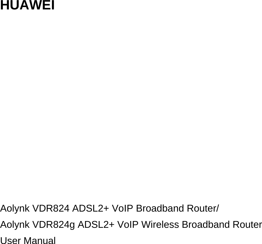
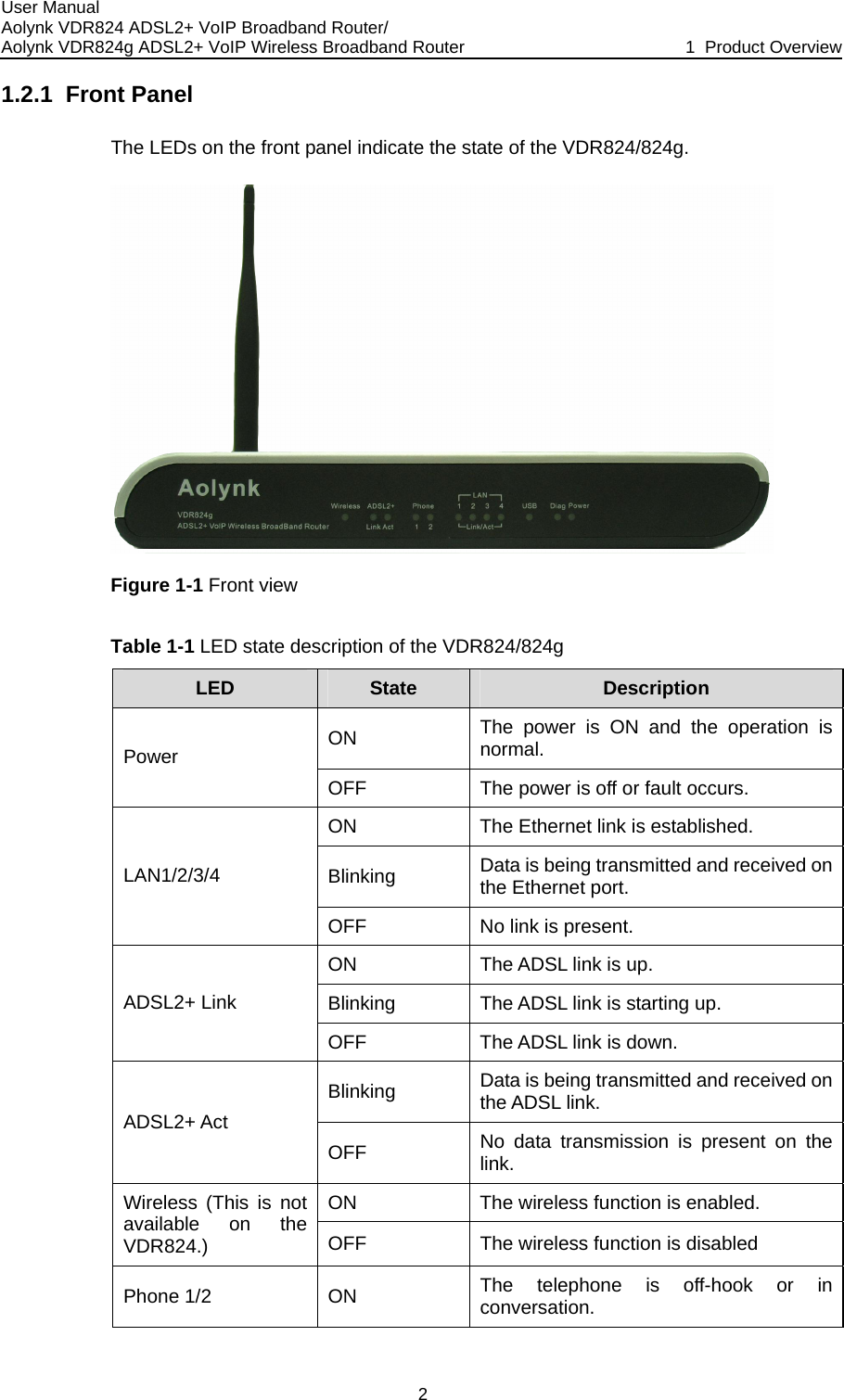
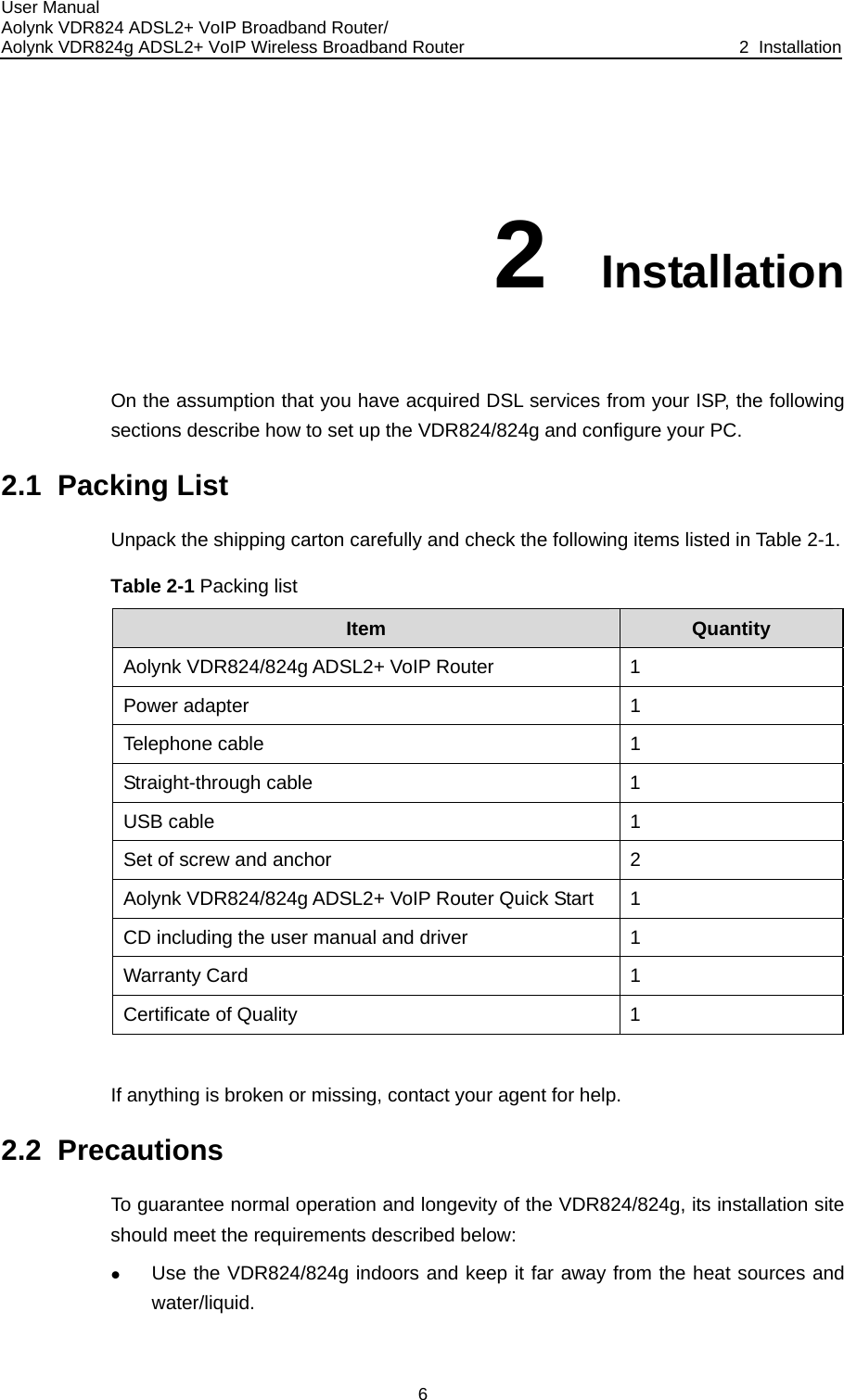
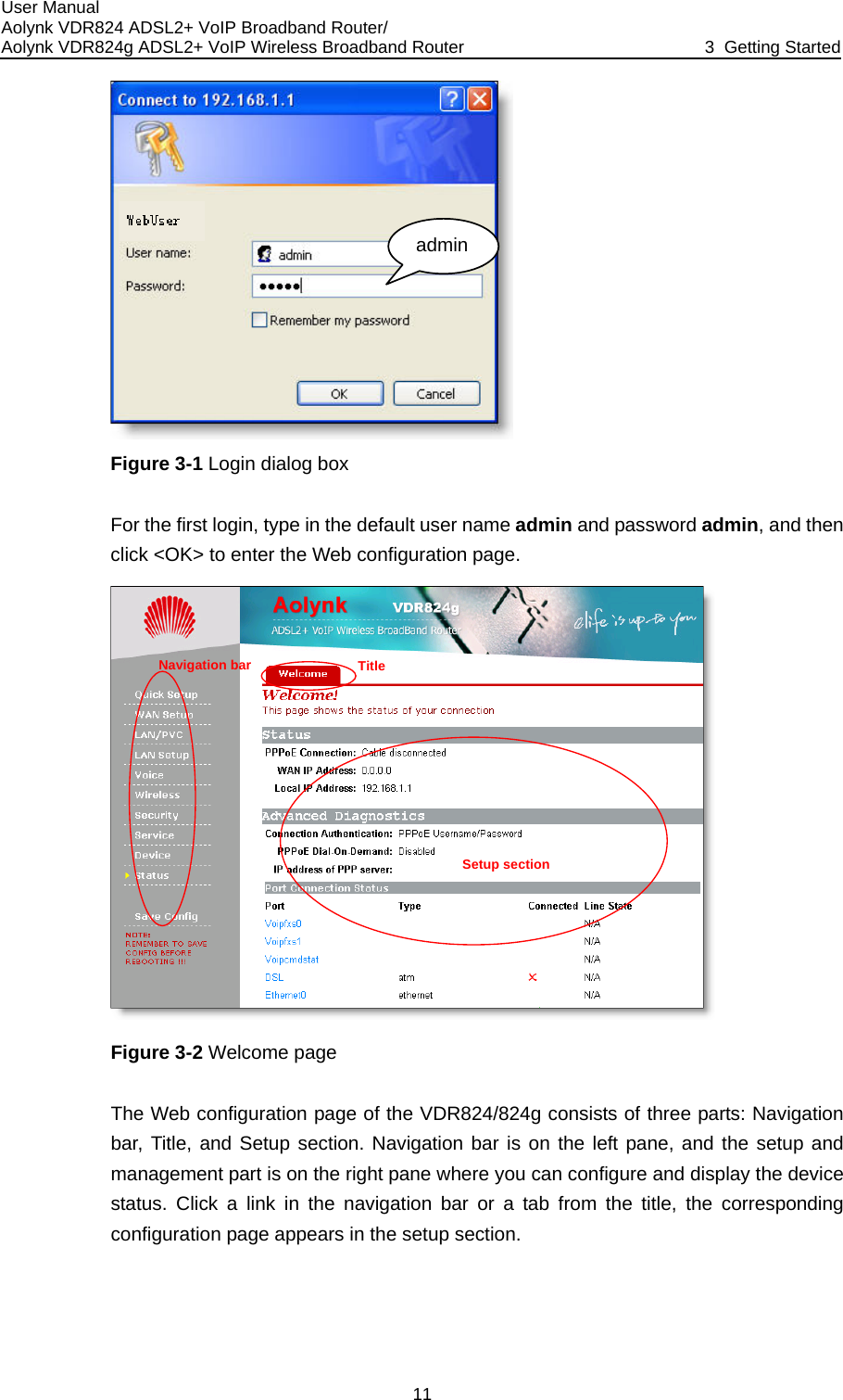
![User Manual Aolynk VDR824 ADSL2+ VoIP Broadband Router/ Aolynk VDR824g ADSL2+ VoIP Wireless Broadband Router 3 Getting Started 10 Getting Started nfiguration pages as the way to manage it. ed. This chapter guides you to be familiar pages. 3.1 Prereb pages, you must configure your later) rk segment as n page. The default IP address of the VDR824/824g Ethernet port is 192.168.1.1. Refer to section 7 “Appendix - TCP/IP Protocol”. III. No proxy server If your PC uses the proxy server to access the Internet, you must disable the proxy 1) Choose [Tool/Internet options] to open the [Internet options] window. 3.2 Logun your Web browser and enter http://192.168.1.1 in the address bar. A login dialog box appears as shown in Figure 3-1. 3 The VDR824/824g offers a series of Web coYou can configure the VDR824/824g as needwith the Web configurationequisite Tasks for Configuration To configure the VDR824/824g through its built-in WPC as the following. I. System requirements z An Ethernet NIC (10Base-T or 10/100Base-T/TX) or a USB port z A Web browser (Microsoft Internet Explorer 5.5, Netscape 6.0 orz TCP/IP protocol employed II. IP address of your PC You must assign an IP address to your PC to make it in the same netwothe VDR824/824g before accessing the configuratioservice. 2) Select the [Connections] tab and click <LAN settings…>. 3) Make sure the Use a proxy server option is not selected. in R](https://usermanual.wiki/Huawei-Technologies/H3CSOHOXDR8X4G.Users-Manual-Part-I/User-Guide-681688-Page-17.png)
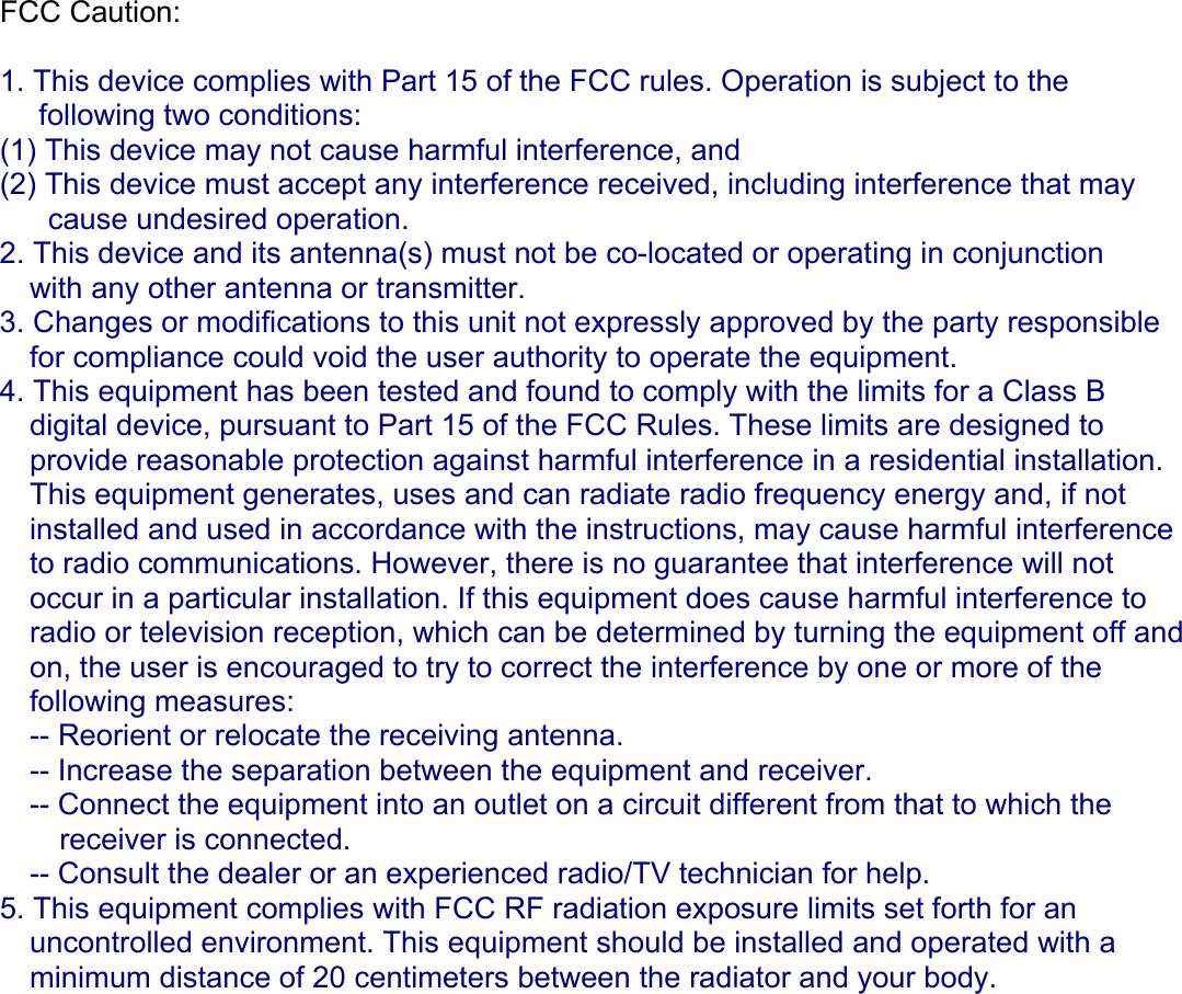
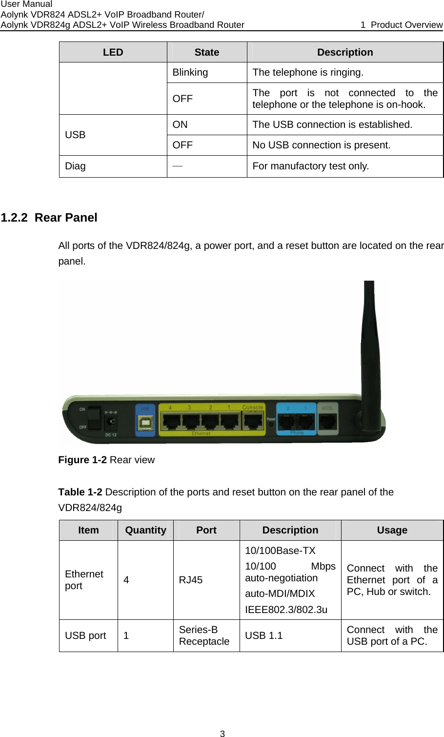
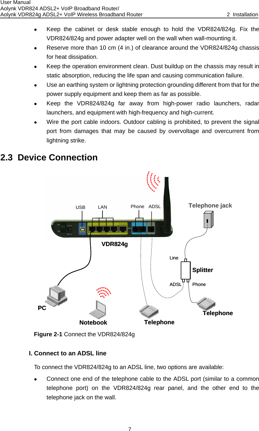
![User Manual Aolynk VDR824 ADSL2+ VoIP Broadband Router/ Aolynk VDR824g ADSL2+ VoIP Wireless Broadband Router 4 Web-based Basic Configuration 14 4 HO 4.1 Quick Setup I. PPPoE Web-based Basic Configuration This chapter describes the basic configuration pages of the VDR824/824g for SOusers to implement its basic functions. For details of advanced configuration, refer to section 5 “Advanced Configuration”. Click [Quick Setup] in the navigation bar to enter the [Quick Start] page on which you can perform some simple settings to access the Internet quickly. Here, two common login types are available: PPPoE and DHCP. lt login type on the page is PPPoE. This type requires you to type in the VPI and VCI values, PPPoE user name and PPPoE password specified by your ISP, and repeat the password for confirmation in the [PPPoE Password (confirm)] text box. Figure 4-1 Quick Setup – PPPoE Login The defau](https://usermanual.wiki/Huawei-Technologies/H3CSOHOXDR8X4G.Users-Manual-Part-I/User-Guide-681688-Page-21.png)
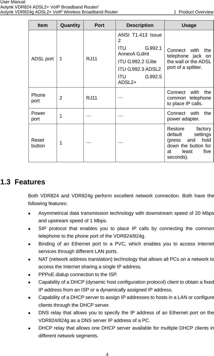
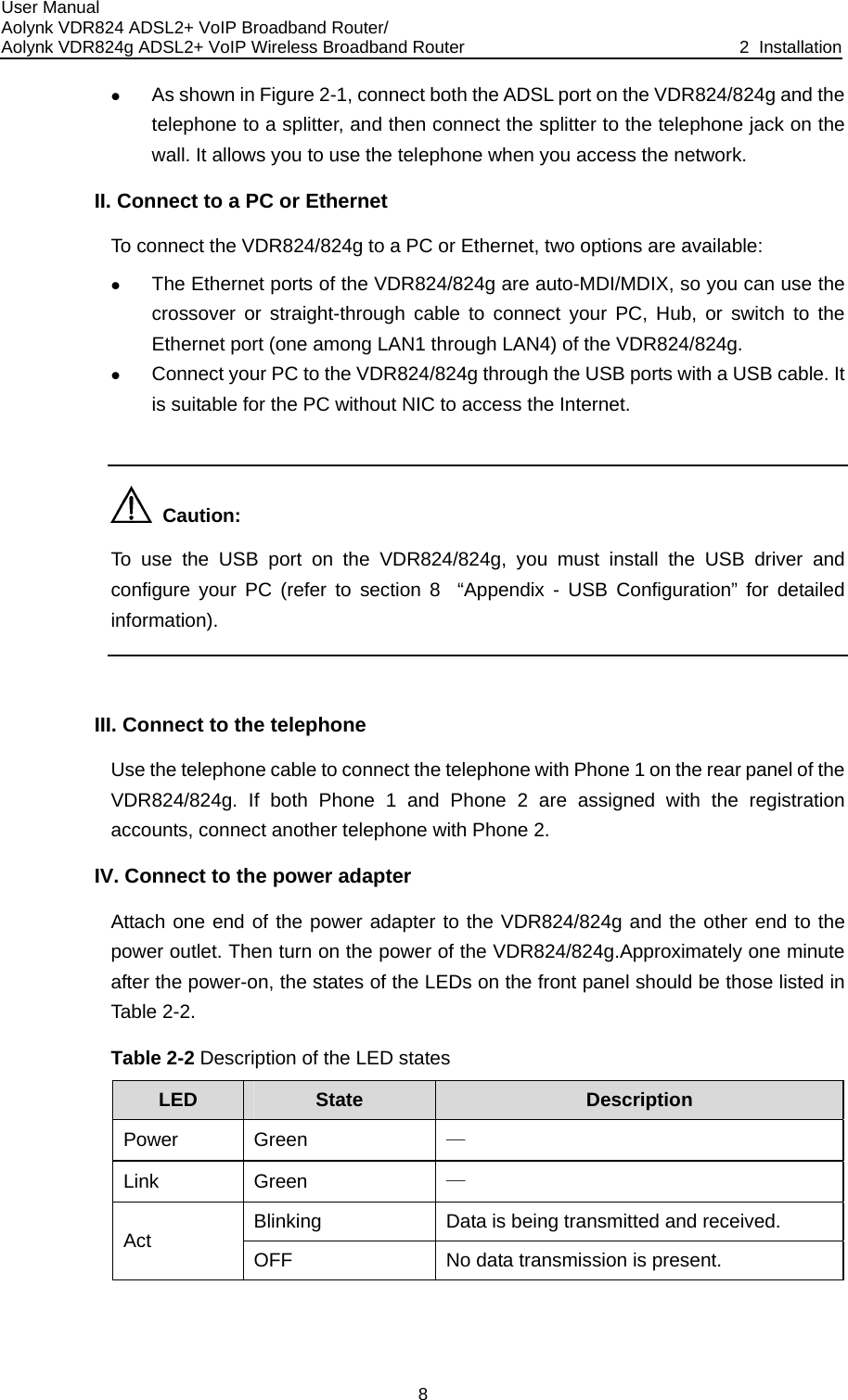
![User Manual Aolynk VDR824 ADSL2+ VoIP Broadband Router/ Aolynk VDR824g ADSL2+ VoIP Wireless Broadband Router 4 Web-based Basic Configuration 15 E When there are multiple PPPoE servers in the network, you can specify the PPPoserver identifier through which the PPPoE client accesses in the [PPPoE Access concentrator] text box. Click <Apply> after the configuration is complete. II. DHCP Figure 4-2 Quick Setup – No Login/DHCP ally, select the and type in the VPI If you can obtain IP addresses from your ISP’s DHCP server automaticNo Login/DHCP option on the [Quick Start] page (see Figure 4-1)and VCI values specified by your ISP on the page (see Figure 4-2). Click <Apply> after the configuration is complete. Caution: Do not set the same VPI and VCI values for DHCP and PPPoE login types. AN Setup 4.2 WClick [WAN Setup] in the navigation bar to enter the corresponding page which three Relay, and DDNS. Click the desired tab to enter its configuration page. 4.2.1 WANset WAN connections in detail, or to modify the service ontabs are available: WAN, DNS This page allows you to attributes. You can access the Internet normally only when these attributes are set correctly.](https://usermanual.wiki/Huawei-Technologies/H3CSOHOXDR8X4G.Users-Manual-Part-I/User-Guide-681688-Page-22.png)
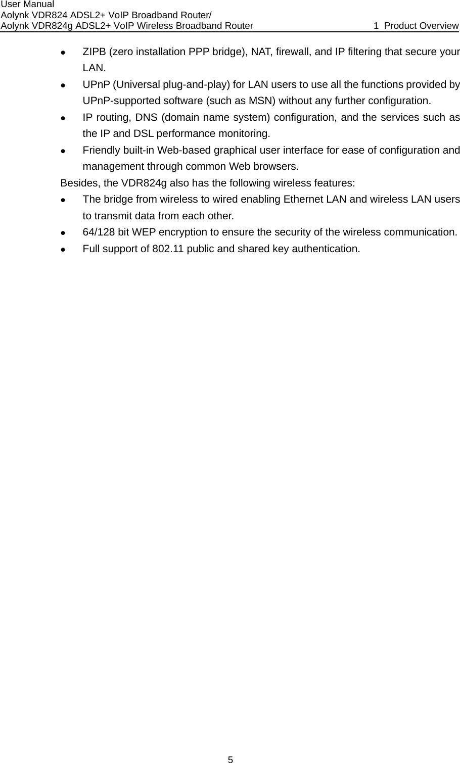
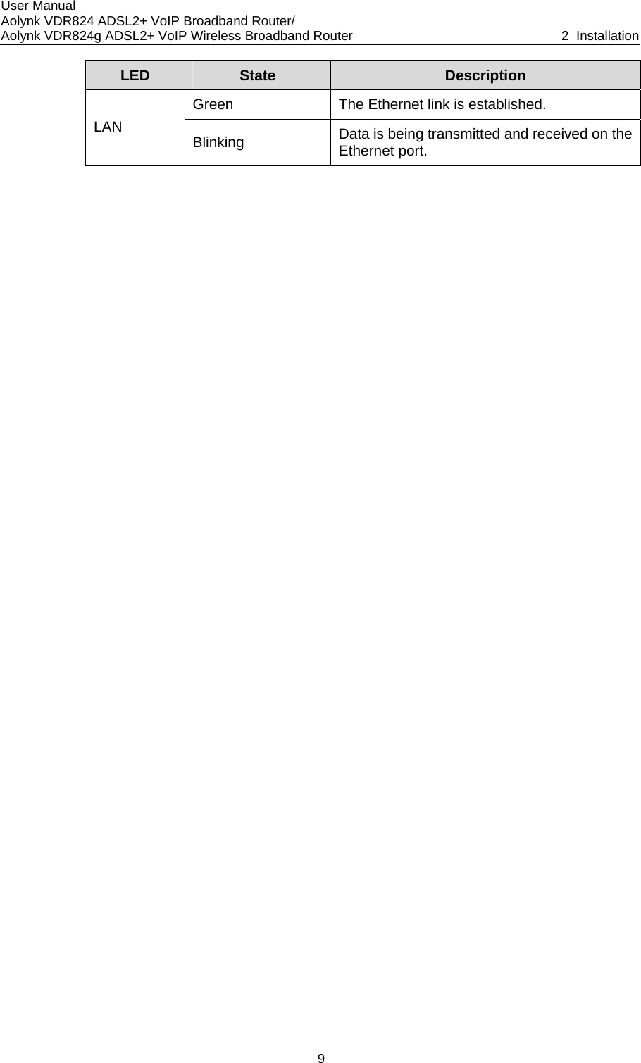
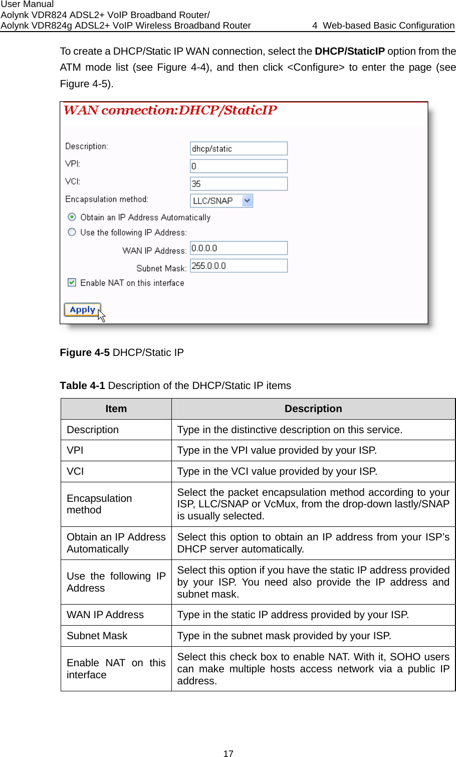
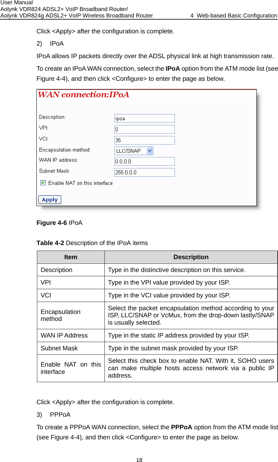
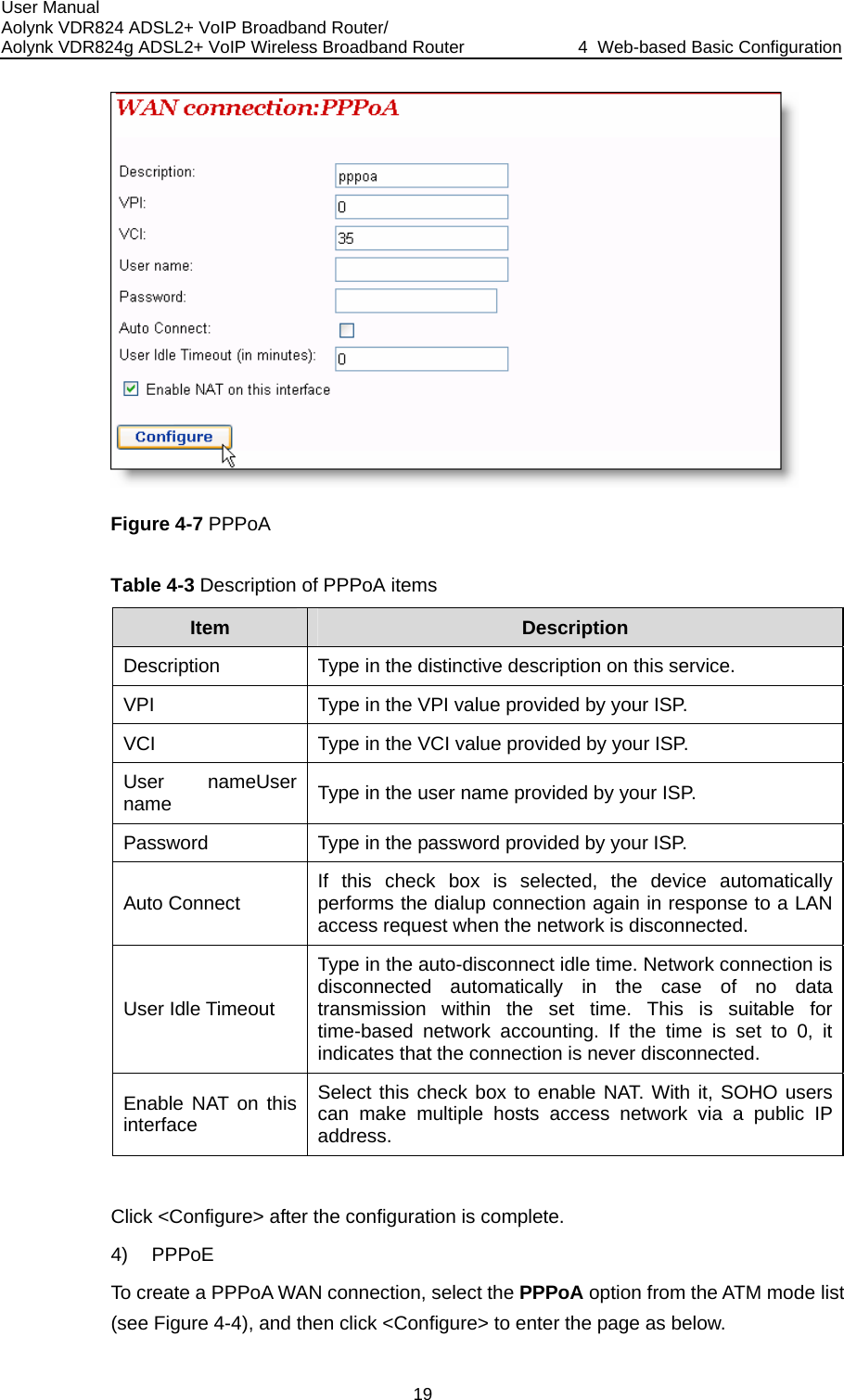
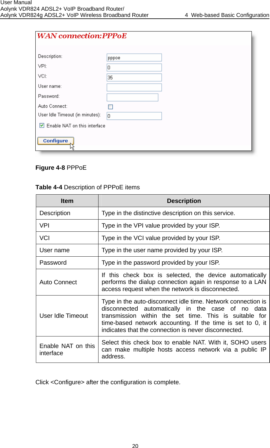
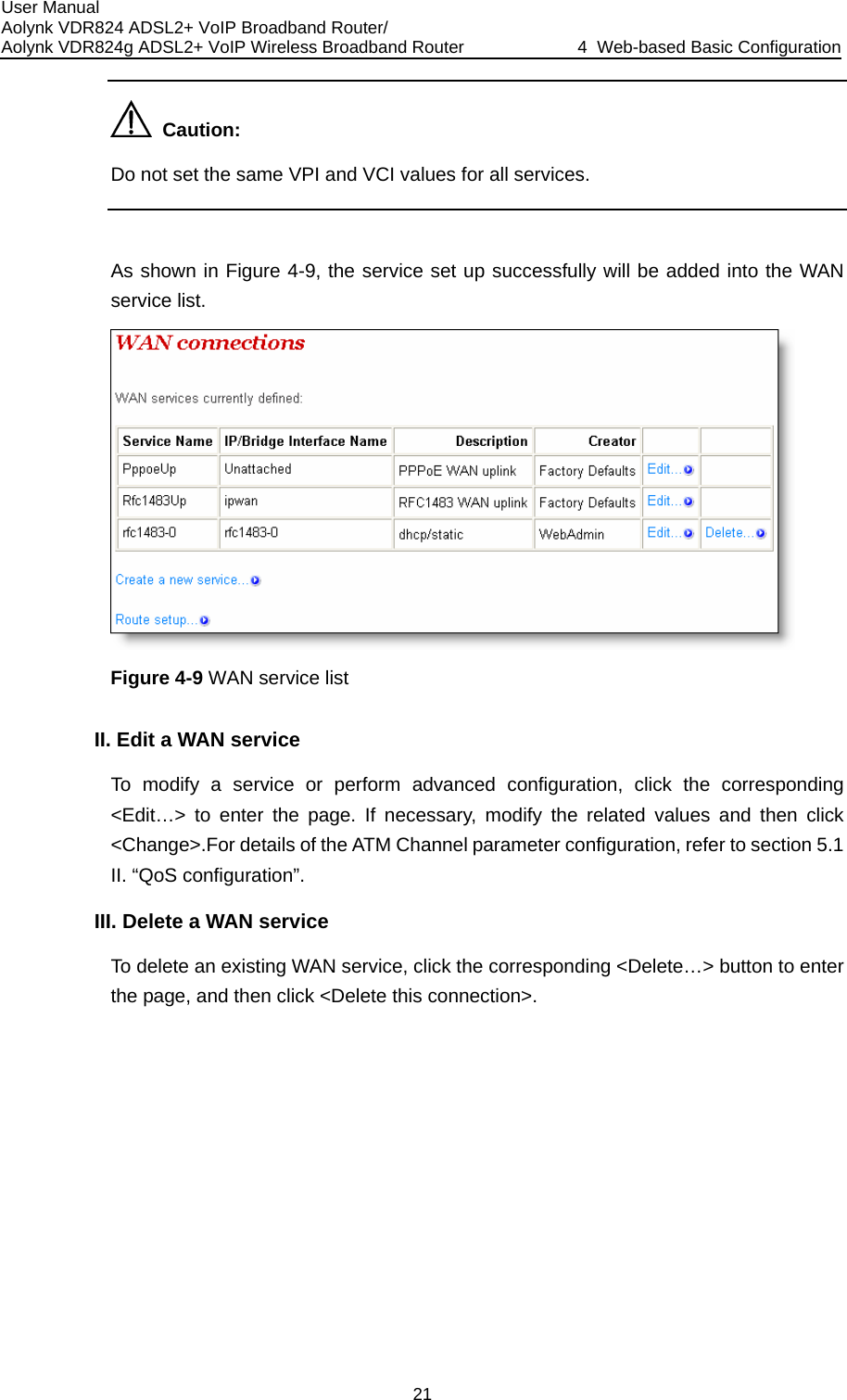
![User Manual Aolynk VDR824 ADSL2+ VoIP Broadband Router/ Aolynk VDR824g ADSL2+ VoIP Wireless Broadband Router 4 Web-based Basic Configuration 16 Figure 4-3 WAN Create a new service To create a new service, click <Create a new service…> to enter the [WAN connectiocreate service] page (see Figure 4-4). I. n: service FCreate a WANThis p and P owing int1The IP address in this m e manually specified or automatically assigned by our ISP. The former requires you to manually specify the DNS server address on the [DNS Relay] page. For details, refer to section 4.2.2 “DNS Relay”. igure 4-4 age provides four modes for PPoE. The follWAN connection: DHCP/StaticIP, IPoA, PPPoAroduces their configurations respectively. ) DHCP/Static IP ode can by](https://usermanual.wiki/Huawei-Technologies/H3CSOHOXDR8X4G.Users-Manual-Part-I/User-Guide-681688-Page-23.png)
![User Manual Aolynk VDR824 ADSL2+ VoIP Broadband Router/ Aolynk VDR824g ADSL2+ VoIP Wireless Broadband Router 4 Web-based Basic Configuration 23 Figure 4-11 DNS Relay (1) To create a new DNS server, type in its IP address, suppose 218.72.1.1, in the [New DNS server IP address] field, and then click <Apply>. This address will be added to the list of the DNS server IP address (see Figure 4-12). NS Relay (2) Figure 4-12 D](https://usermanual.wiki/Huawei-Technologies/H3CSOHOXDR8X4G.Users-Manual-Part-I/User-Guide-681688-Page-30.png)
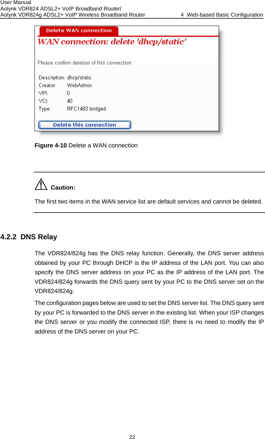
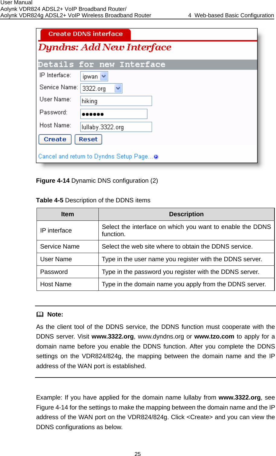
![User Manual Aolynk VDR824 ADSL2+ VoIP Broadband Router/ Aolynk VDR824g ADSL2+ VoIP Wireless Broadband Router 4 Web-based Basic Configuration 24 Caution: In the list of DNS server IP addresses, the first address should be for the primary DNSserver, the second for the secondary DNS server, and so on. To modify the IP address of the DNS server in the list, modify it directly in the field and then click <Apply>. To delete the existing DNS server, select the corresponding [Delete?] check box andthen click <Apply>. Dynamic Domain Name Service (DDNS). By way of PPPoE or static IP, the IP addr 4.2.3 DDNS ss AN port obtained is unfixed, making it inconvenient for the Internet users to problem. After you set the DDNS function, the VDR824/824g update the mapping between the domain name and the IP address o access the LAN through the domain name. ethat the Waccess the LAN server. DDNS solves thisautomatically, ensuring the Internet users t Figure 4-13 Dynamic DNS configuration (1) Click <Add a new dyndns interface…> to enter the DDNS configuration page (see Figure 4-14).](https://usermanual.wiki/Huawei-Technologies/H3CSOHOXDR8X4G.Users-Manual-Part-I/User-Guide-681688-Page-31.png)
![User Manual Aolynk VDR824 ADSL2+ VoIP Broadband Router/ Aolynk VDR824g ADSL2+ VoIP Wireless Broadband Router 4 Web-based Basic Configuration 26 uration, nt DDNS e three ter your 4.3.1 LAN ttribute values for the Ethernet port and to configure virtual interfaces. Figure 4-15 DDNS configuration succeeds To delete the DDNS configuration, click <Delete>. To clear all the DDNS configclick <Clear All Interfaces>. To view the detailed configuration of the curreinterface, click <Show Details…>. 4.3 LAN Setup Click [LAN Setup] in the navigation bar to enter the corresponding page whertabs are available: LAN, DHCP Server, and DHCP Relay. Click any tab to endesired configuration page. This page allows you to set a](https://usermanual.wiki/Huawei-Technologies/H3CSOHOXDR8X4G.Users-Manual-Part-I/User-Guide-681688-Page-33.png)
![User Manual Aolynk VDR824 ADSL2+ VoIP Broadband Router/ Aolynk VDR824g ADSL2+ VoIP Wireless Broadband Router 4 Web-based Basic Configuration 27 I. mask to the …> to lues of Figure 4-16 LAN connections Set a LAN port To change the IP address of the LAN port, type in the IP address and/or subnetdirectly in the corresponding field, and then click <Apply>.For related introductionIP address, refer to section 9 “Appendix - IP Address and Subnet Mask” To perform advanced configuration on the attribute of LAN port, click <Advancedenter the [Edit iplan] page as shown in Figure 4-17.If necessary, modify the vaoptions and click <Change>.](https://usermanual.wiki/Huawei-Technologies/H3CSOHOXDR8X4G.Users-Manual-Part-I/User-Guide-681688-Page-34.png)
![User Manual Aolynk VDR824 ADSL2+ VoIP Broadband Router/ Aolynk VDR824g ADSL2+ VoIP Wireless Broadband Router 4 Web-based Basic Configuration 28 Modify the iplan interface IIe [LAN Figure 4-17 . Create a new virtual interface To create a new virtual interface, click <Create a new virtual interface…> on thconnections] page (see Figure 4-16) to enter the page as below. Figure 4-18 Create a virtual interface Type in the IP address and subnet mask (you cannot configure the IP address virtual interface and that of the LAN port to be in the same subnet) and click <Aof the ply>. ual interface is displayed on the page as below. pThe information on this virt](https://usermanual.wiki/Huawei-Technologies/H3CSOHOXDR8X4G.Users-Manual-Part-I/User-Guide-681688-Page-35.png)
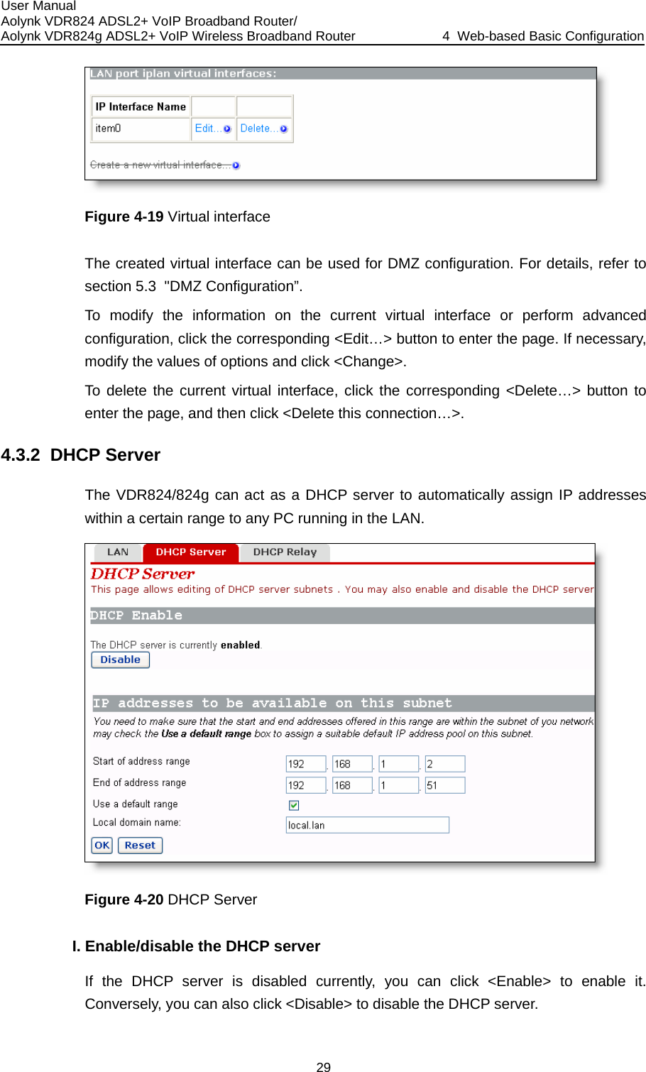
![User Manual Aolynk VDR824 ADSL2+ VoIP Broadband Router/ Aolynk VDR824g ADSL2+ VoIP Wireless Broadband Router 4 Web-based Basic Configuration 30 efined nded efault IP do not he start and in the e by entering n also set 4.3.3 DHCP Relay the DHCP client on II. Set a DHCP server The enabled DHCP server can assign the IP addresses, according to the daddress range on this page, to the DHCP client sending a request. It is recommethat you select the [Use a default range] check box to assign a suitable daddress pool for the current subnet. If necessary, you can also set the DHCP address range manually. In this case, select the [Use a default range] check box (by removing the tick). Type in tend IP addresses in the corresponding fields, and then click <OK>. If necessary, you can type in commonly used DNS suffixes such as google.com[Local domain name] text box. Thus, you can access the Google homepaghttp://www/ in the Web browser. Small and medium-sized enterprises catheir own DNS suffixes here while home users need not. The VDR824/824g has the DHCP relay function to transmit packets betweenclient and server in different network segments, thereby making the DHCPmultiple networks use the DHCP server across these segments.](https://usermanual.wiki/Huawei-Technologies/H3CSOHOXDR8X4G.Users-Manual-Part-I/User-Guide-681688-Page-37.png)
![User Manual Aolynk VDR824 ADSL2+ VoIP Broadband Router/ Aolynk VDR824g ADSL2+ VoIP Wireless Broadband Router 4 Web-based Basic Configuration 31 I. Specify a DHCP relay interface On the [DHCP Relay] page (see Figure 4-21), select an interface (suppose iplan) from rop-down list to apply the DHCP relay function, and then click Figure 4-21 DHCP Relay page the [New IP interface] d<Add>. This interface will appear on the page as below. Figure 4-22 New IP interface](https://usermanual.wiki/Huawei-Technologies/H3CSOHOXDR8X4G.Users-Manual-Part-I/User-Guide-681688-Page-38.png)
![User Manual Aolynk VDR824 ADSL2+ VoIP Broadband Router/ Aolynk VDR824g ADSL2+ VoIP Wireless Broadband Router 4 Web-based Basic Configuration 32 Click <Apply> in Figure 4-22 to apply this configuration, and the “Changes successfully applied” information appear on the page as below. o specify other interfaces. Figure 4-23 The applied new IP interface Follow the above instructions tTo delete this interface, select the corresponding [Delete?] check box and click <Apply>. Caution: z DHCP relay in pair. For example, to set the host connected to the LAN port to communicate with the DHCP server on the WAN side, you need to configure the iplan and ipwan to be the DHCP relay interfaces concurrently. z If no interface is specified, the VDR824/824g enables the DHCP rYou should configure two interfaces (sending and receiving packets respectively) of elay function on all interfaces by default. II. Set a DHCP server ll be To add a DHCP server, type in the IP address (suppose 20.2.0.100) of the DHCP server in the [New DHCP server IP address] field (see Figure 4-21). This address wiadded to the list of DHCP server IP addresses as below.](https://usermanual.wiki/Huawei-Technologies/H3CSOHOXDR8X4G.Users-Manual-Part-I/User-Guide-681688-Page-39.png)
![User Manual Aolynk VDR824 ADSL2+ VoIP Broadband Router/ Aolynk VDR824g ADSL2+ VoIP Wireless Broadband Router 4 Web-based Basic Configuration 33 ify the IP address of the DHCP server in the list, modify it directly in the field and then click <Apply>. DHCP server, select the corresponding [Delete?] check box and IInfiguration is complete. The cannot be enabled se the DHCP server ) to enter the DHCP server Figure 4-25). If the it. Conversely, click Figure 4-24 Set a DHCP server To modTo delete the existingthen click <Apply>. I. Enable/disable DHCP relay You need to enable the DHCP relay function after the cofunctions of DHCP server and DHCP relay of the VDR824/824g concurrently. By default, you cannot enable the DHCP relay becauis already enabled. The prompt is display as shown in Figure 4-21. Click <DHCP Server> on the above page (see Figure 4-24page, click <Disable> and thus <Enable> appears on the page (seeDHCP relay is disabled currently, you can click <Enable> to enable <Disable> to disable it. Figure 4-25 Enable/disable the DHCP relay](https://usermanual.wiki/Huawei-Technologies/H3CSOHOXDR8X4G.Users-Manual-Part-I/User-Guide-681688-Page-40.png)
![User Manual Aolynk VDR824 ADSL2+ VoIP Broadband Router/ Aolynk VDR824g ADSL2+ VoIP Wireless Broadband Router 4 Web-based Basic Configuration 34 Caution: T spe rface and ce corresponding to the network where the DHCP sc te with the n interface, you must disable NAT betwe al into ensure the DHCPcified interelay to be effective, you need to disable NAT between the the interfaerver resides. For exommunicaample, to specify the host connected to the LAN port to DHCP server on the ipwaen the intern erface (iplan) and the external interface (ipwan). 4.4 VoicC e nav are available: Setting and SpeedDial. Click any tab to enter your desired configuration age. Setting e lick [Voice] in th igation bar to enter the corresponding page where two tabs p4.4.1 Phone PortBefore using the telephone connected to the VDR824/824g to place IP calls, you need to set here the registration information about phone port provided by your ISP, and register Phone 2 of the device with the SIP server. rts Figure 4-26 Set the phone po](https://usermanual.wiki/Huawei-Technologies/H3CSOHOXDR8X4G.Users-Manual-Part-I/User-Guide-681688-Page-41.png)
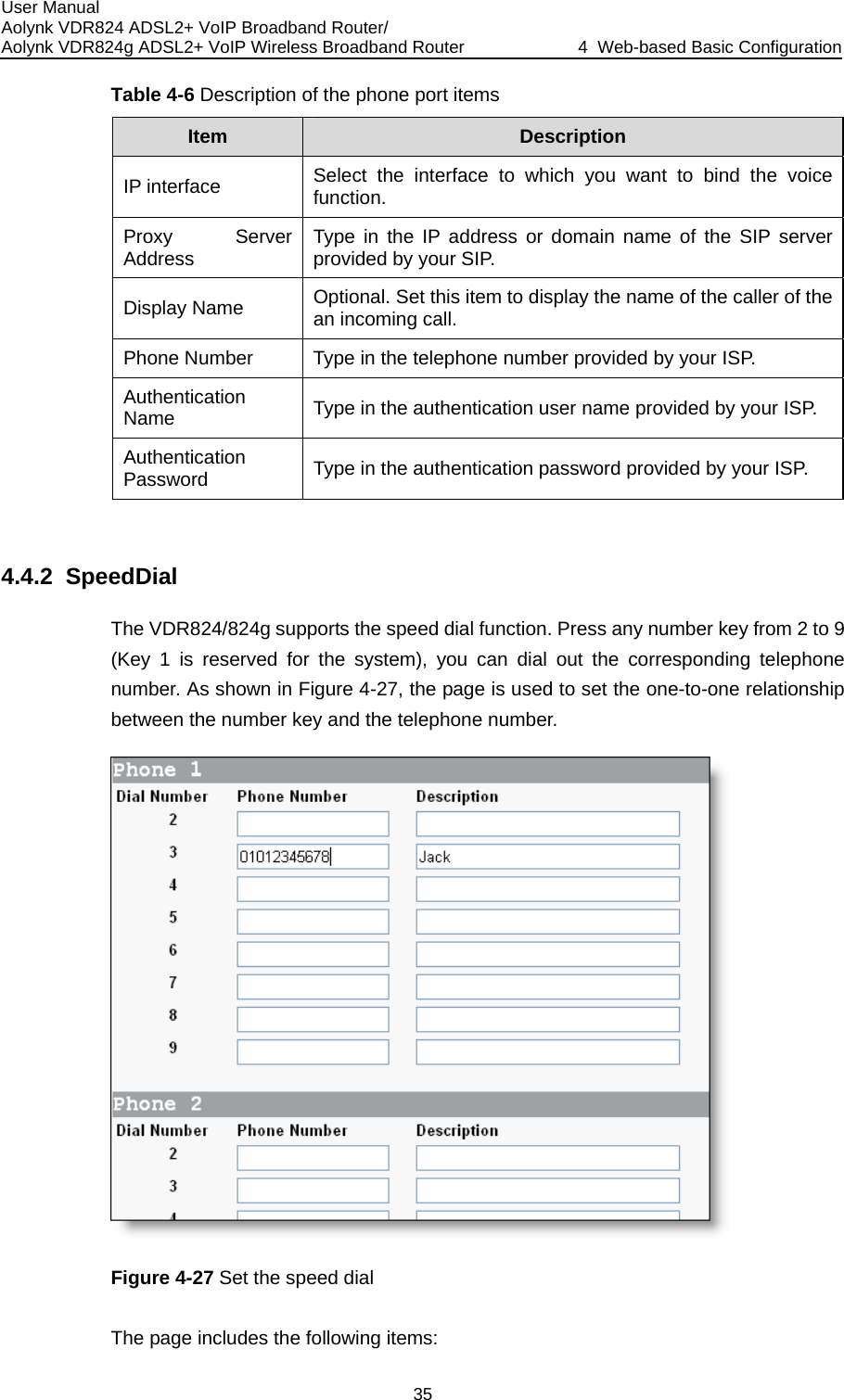
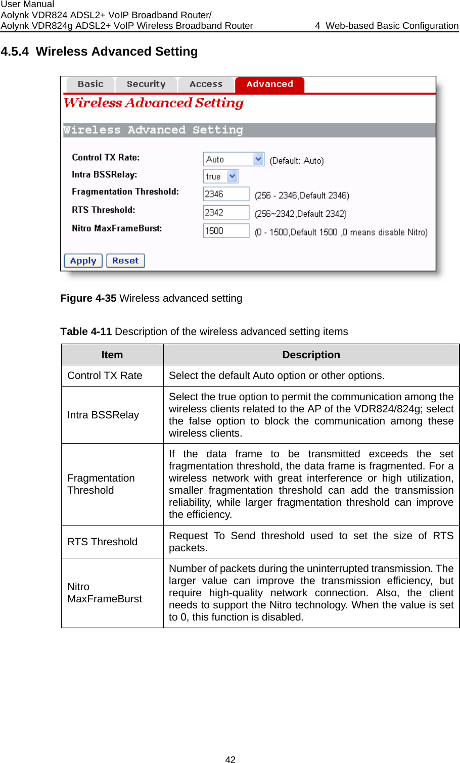
![User Manual Aolynk VDR824 ADSL2+ VoIP Broadband Router/ Aolynk VDR824g ADSL2+ VoIP Wireless Broadband Router 4 Web-based Basic Configuration 36 ponds to the phone number xt to it. z Number: Telephone number of a contz Descriptiont. For example, af connected to P01012345678. C r the setting you have made. 4.5 Wireless z Dial Number: Key number of the telephone. It corresset nePhone act. : Related information about the number, for example, name of the ter the setting as shown in Figure 4-27 (suppose that the telephone ishone 1), you can just press Key 3 to quickly call Jack’s number lick <Apply> aftecontac Note: N fun for the VDR824o wireless ction is available on the VDR824. What describes in this section is onlyg users. C s] bar to enter the corresponding page where four tabs ble: Basic, Security, Access and Advanced. Click any tab to enter your esired configuration page. lick [Wireles in the navigationare availad4.5.1 Wireless Basic Setting This page allows you to set the basic wireless network parameters. Figure 4-28 Wireless basic setting](https://usermanual.wiki/Huawei-Technologies/H3CSOHOXDR8X4G.Users-Manual-Part-I/User-Guide-681688-Page-43.png)
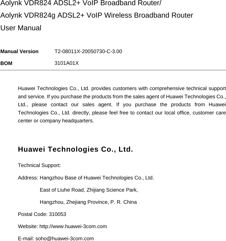
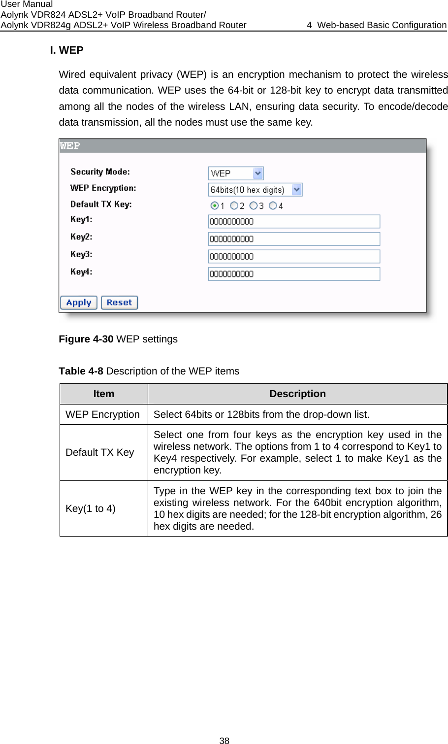
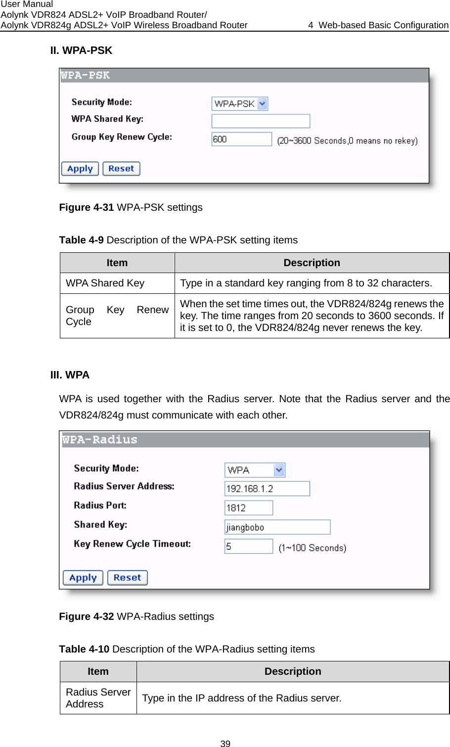
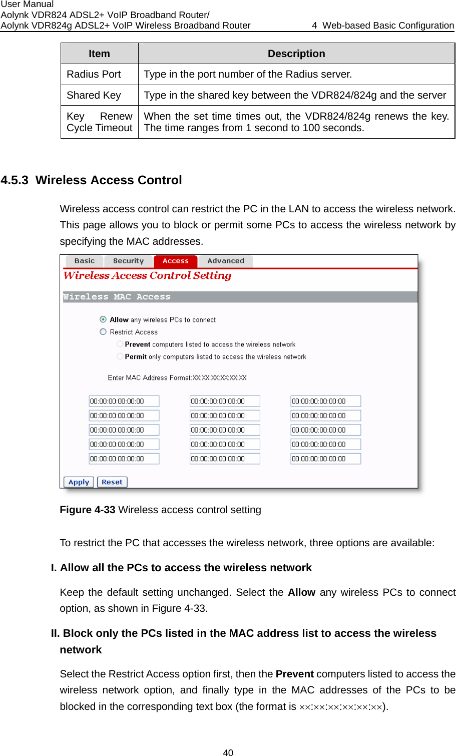
![User Manual Aolynk VDR824 ADSL2+ VoIP Broadband Router/ Aolynk VDR824g ADSL2+ VoIP Wireless Broadband Router 4 Web-based Basic Configuration 37 -7 Description of the wireless basic setting items Table 4Item Description Wireless Network Select the wireless network mode from the drop-down list. If both 802.11g-based and 802.11b-based devices are available in your network, keep the default Mixed option802.11g-based device is available in your nMode unchanged; if only the etwork, select the G-Only option; if only the 802.11b-based device is available in your network, select the B-Only option. To disable the wireless network, select the Disable option. SSID Service set identifier, the unique identifier shared by the VDR824g and other clients in the same wireless network. The SSID of all the nodes must be the same and cannot exceed 32 characters. Wireless Channel Select the appropriate wireless channel from the drop-down list. The channel beyond the control range can be accepted. Ensure that the nodes in the same wireless LAN use the same channel, or automatically select the channel when clients are connected to the access point. Wireless SSID The wireless client detects the VDR824g SSID when searching for the local accessible wireless network. To make the VDR824 broadcast the SSID, select the Enable option, otherwise, select the ption. gBroadcast Disable o 4.5.2 Wireless Security Setting T u security. his page allows yo to set the wireless data encryption to ensure the Figure 4-29 Wireless security setting Three encryption options are available from the [Security Mode] drop-down list: WEP, WPA-PSK, and WPA. Select any option to display the corresponding configuration items. To disable the encryption, select the Disabled option. The following introduces their configurations respectively.](https://usermanual.wiki/Huawei-Technologies/H3CSOHOXDR8X4G.Users-Manual-Part-I/User-Guide-681688-Page-44.png)
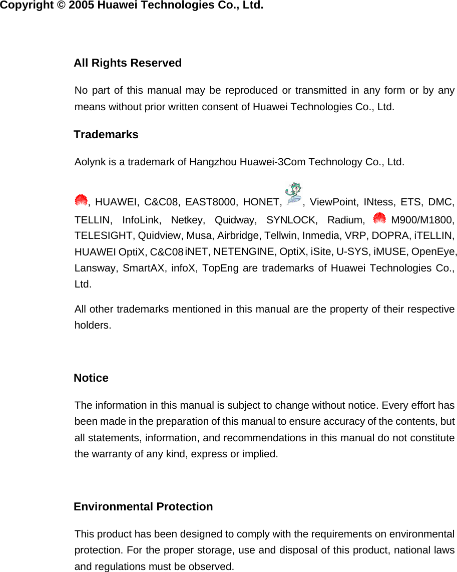
![User Manual Aolynk VDR824 ADSL2+ VoIP Broadband Router/ Aolynk VDR824g ADSL2+ VoIP Wireless Broadband Router 4 Web-based Basic Configuration 43 4.6 Device e five tabs are ab to enter 4.6.1 Passw/824g via two user s while the common n enter the following [Password] page to change the login passwords for two users. The Click [Device] in the navigation bar to enter the corresponding page wheravailable: Password, Remote, Restart, Backup and Upgrade. Click any tyour desired configuration page. ord You can access log into the Web configuration page of VDR824name: admin and user. The administrator has the maximum rightuser can only access part of the configuration pages. Only the administrator cacommon user can only change its own password. 4.6.2 Remote Access If remote access is enabled, you can view the current configuration page and manage the VDR824/824g remotely. By default, the remote access is enabled and the idle timeout time is set to 0 (see Figure 4-37). In this case, remote access is kept alive. Figure 4-36 Change the password By default, admin and user are the passwords for administrator and common user respectively. To change the password, type in the related information in the [Old Password], [New Password] and [Confirm Password] text boxes, and then click <Apply>.](https://usermanual.wiki/Huawei-Technologies/H3CSOHOXDR8X4G.Users-Manual-Part-I/User-Guide-681688-Page-50.png)
![User Manual Aolynk VDR824 ADSL2+ VoIP Broadband Router/ Aolynk VDR824g ADSL2+ VoIP Wireless Broadband Router 4 Web-based Basic Configuration 44 Figure 4-37 Remote access page – remote access enabled ates the port for remote management is 8000, so you can manage the ser. n Figure 4-37 indicVDR824/824g remotely by entering http://xxx.xxx.xxx.xxx:8000 in your Web browThe xxx.xxx.xxx.xxx is the IP address of the WAN port on the VDR824/824g. If multiple WAN services are configured and all of them obtain the IP addresses, the IP address ofany service can be used for remote access. To disable the remote access, click <Disable> on the [Remote Access] page to opethe page as below. this case, you can set the idle timeout time to a desired value other than 0 in the text page. Thus, when you click <Enable> to enable the remote access next time, the VDR82 psed idle time and terminates the remote connection to avoi acks when the elapsed idle time exceeds the set idle time. Figure 4-38 Remote access page – remote access disabled Inbox on the 4/824g tracks the elad remote att](https://usermanual.wiki/Huawei-Technologies/H3CSOHOXDR8X4G.Users-Manual-Part-I/User-Guide-681688-Page-51.png)
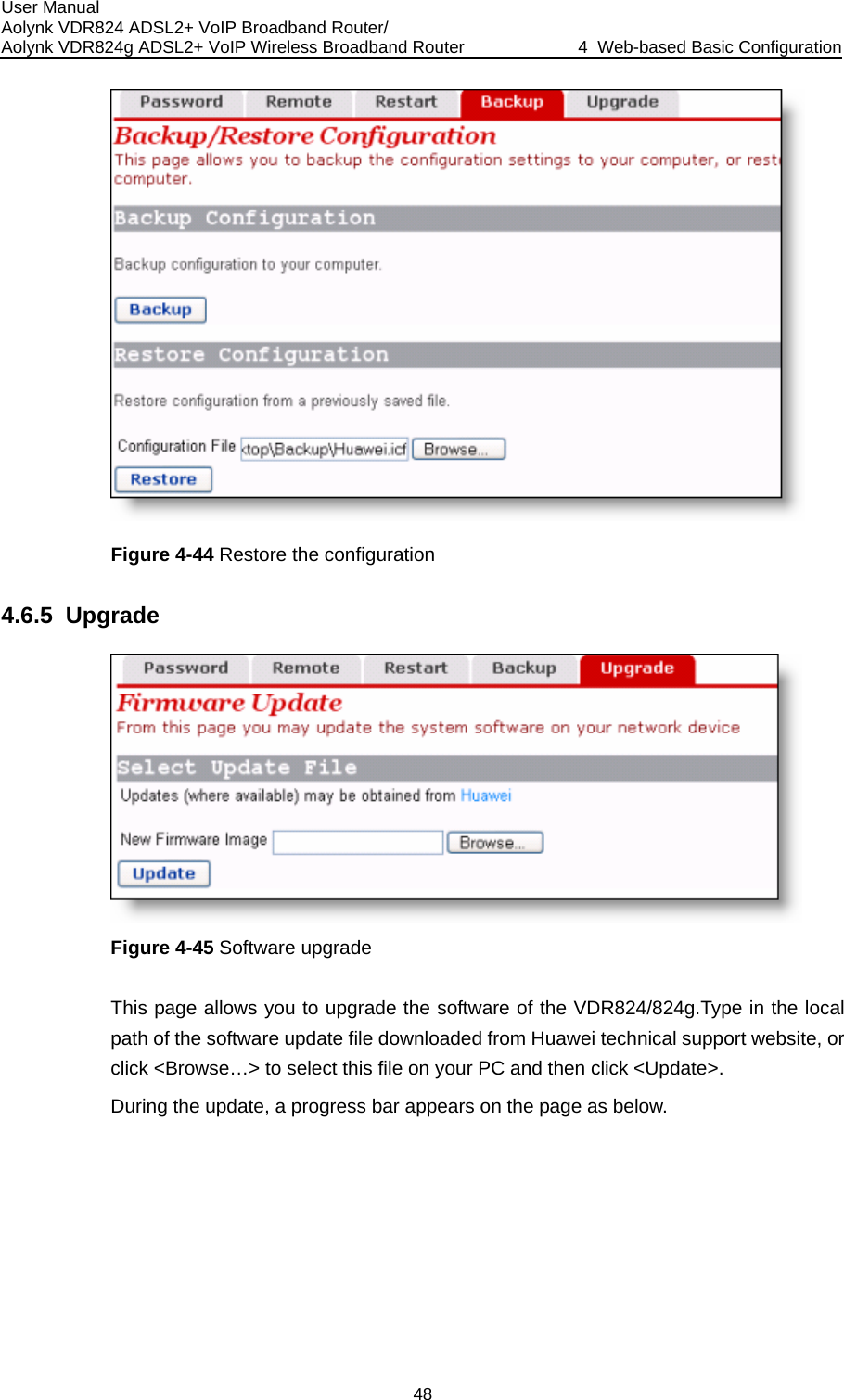
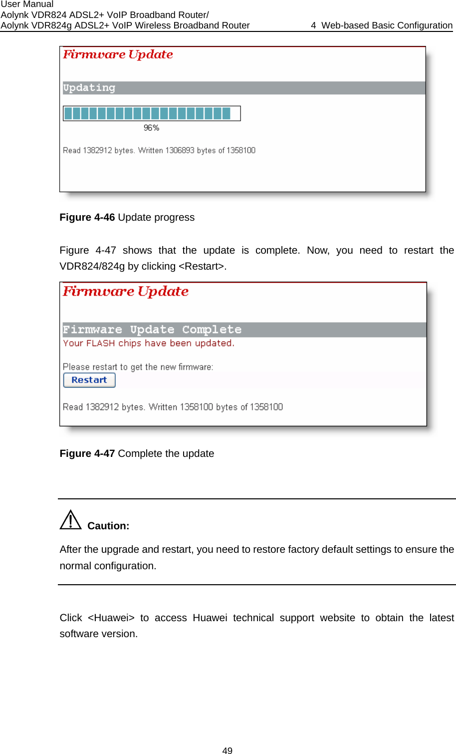
![User Manual Aolynk VDR824 ADSL2+ VoIP Broadband Router/ Aolynk VDR824g ADSL2+ VoIP Wireless Broadband Router 4 Web-based Basic Configuration 45 Caution: A remote connection is maintained only when the idle timeout time is set to 0. If you set the timeout time to another value, remote access is disabled automatically whethe VDR824/824g restarts. Because remote access is enabled by default, you need to configure the passwoprevent network invasion by the Internet users. never rd to Restoring Factory Default Settings This page allows you to restart the VDR824/824g, or reset all configurationsdefault settings. 4.6.3 Restarting/ to factory elect the [Reset to factory Figure 4-39 Restart Router page To restart the VDR824/824g, click <Restart>. To reset all configurations to the factory default settings, sdefault settings] check box and click <Restart>. Caution: It may take several seconds to restart the VDR824/824g. 4.6.4 Backing Up/Restoring Configuration This page allows you to back up the current configuration to your PC, or restore the configuration from a previously saved file.](https://usermanual.wiki/Huawei-Technologies/H3CSOHOXDR8X4G.Users-Manual-Part-I/User-Guide-681688-Page-52.png)
![User Manual Aolynk VDR824 ADSL2+ VoIP Broadband Router/ Aolynk VDR824g ADSL2+ VoIP Wireless Broadband Router 4 Web-based Basic Configuration 46 ration page I. Figure 4-40 Backup/Restore ConfiguBack up the current configuration Click <Backup> to open the [File Download] dialog box as below. Figure 4-41 File Download dialog box Click <Save> to open the [Save As] window as below.](https://usermanual.wiki/Huawei-Technologies/H3CSOHOXDR8X4G.Users-Manual-Part-I/User-Guide-681688-Page-53.png)
![User Manual Aolynk VDR824 ADSL2+ VoIP Broadband Router/ Aolynk VDR824g ADSL2+ VoIP Wireless Broadband Router 4 Web-based Basic Configuration 47 Figure 4-42 Save the configuration file Select a directory to save the file and type in a valid file name (with the .icf suffix), and ck <Save> to back up the current configuration to the file. then cliII. Use the file to restore the configuration To use the previously saved file to restore the configuration, click <Browse…> in Figure 4-40 to open the [Choose file] window as below. Figure 4-43 Choose the backup file Find the configuration file and then click <Open> to open the page as below. Click <Restore> to use the file to restore the configuration.](https://usermanual.wiki/Huawei-Technologies/H3CSOHOXDR8X4G.Users-Manual-Part-I/User-Guide-681688-Page-54.png)
![User Manual Aolynk VDR824 ADSL2+ VoIP Broadband Router/ Aolynk VDR824g ADSL2+ VoIP Wireless Broadband Router 4 Web-based Basic Configuration 50 4.7 Stbs red 4.7.1 Status atus Click [Status] in the navigation bar to enter the corresponding page where three taare available: Status, Log, and Search Service. Click any tab to enter your desiconfiguration page. Figure 4-48 Status configuration page This page displays useful information about the configuration of the VDR824/824g, n) z Routing table z Connection status of current DSL, Ethernet and USB port z WAN port status z LAN port status z Statistics on all interfaces 4.7.2 Log This page records all types of events occurring during the running of the DR811/814. including: z Details of network connection z Some important system information (hardware and version informatio](https://usermanual.wiki/Huawei-Technologies/H3CSOHOXDR8X4G.Users-Manual-Part-I/User-Guide-681688-Page-57.png)
![User Manual Aolynk VDR824 ADSL2+ VoIP Broadband Router/ Aolynk VDR824g ADSL2+ VoIP Wireless Broadband Router 4 Web-based Basic Configuration 51 corresponding event information. Figure 4-49 Log The drop-down list in the [Select events to view] section includes the options as shown in the figure below. Select an event type to view the Click <Clear these entries> to clear the currently displaThe [Edit Scan PVC] page allows you to search the your ISP has configured PVC services within the sethese PVC services will be automatically configured to Connections] page until the number of services reacheyed events. 4.7.3 PVC Search currently unused PVC settings. If archable range, after the search, the service list on the [WAN list. s eight in this](https://usermanual.wiki/Huawei-Technologies/H3CSOHOXDR8X4G.Users-Manual-Part-I/User-Guide-681688-Page-58.png)
![User Manual Aolynk VDR824 ADSL2+ VoIP Broadband Router/ Aolynk VDR824g ADSL2+ VoIP Wireless Broadband Router 4 Web-based Basic Configuration 52 Figure 4-50 PVC Scan page Select the true option from the drop-down list in Figure 4-50, and then click <Change> to start the search. It may take about five minutes. Figure 4-51 Search PVC , to AN service list as below. As shown in Figure 4-51, two PVCs are found. Click [WAN Setup] in the navigation baryou will find that two services found by the VDR824/824g are automatically addedthe W](https://usermanual.wiki/Huawei-Technologies/H3CSOHOXDR8X4G.Users-Manual-Part-I/User-Guide-681688-Page-59.png)
![User Manual Aolynk VDR824 ADSL2+ VoIP Broadband Router/ Aolynk VDR824g ADSL2+ VoIP Wireless Broadband Router 4 Web-based Basic Configuration 53 Figure 4-52 Add the found services automatically d, you need to edit these automatically added 4.8 Savation] page after all the configurations are complete. Click If the PPPoE or PPPoA service is founservices by typing in a user name and a password. e the Configuration Enter the [Save configur<Save> to save your configurations so that they take effect when the VDR824/824g restarts. Figure 4-53 Save the configuration Caution: Do save your settings, otherwise, they will be lost after the VDR824/824g restarts.](https://usermanual.wiki/Huawei-Technologies/H3CSOHOXDR8X4G.Users-Manual-Part-I/User-Guide-681688-Page-60.png)