Huawei Technologies H3CSOHOXDR8X4G VoIP Wireless BroadbandRouter User Manual
Huawei Technologies Co.,Ltd VoIP Wireless BroadbandRouter
Contents
- 1. Users Manual Part II
- 2. Users Manual Part I
Users Manual Part I
HUAWEI
Aolynk VDR824 ADSL2+ VoIP Broadband Router/
Aolynk VDR824g ADSL2+ VoIP Wireless Broadband Router
User Manual
FCC Caution:
1. This device complies with Part 15 of the FCC rules. Operation is subject to the
following two conditions:
(1) This device may not cause harmful interference, and
(2) This device must accept any interference received, including interference that may
cause undesired operation.
2. This device and its antenna(s) must not be co-located or operating in conjunction
with any other antenna or transmitter.
3. Changes or modifications to this unit not expressly approved by the party responsible
for compliance could void the user authority to operate the equipment.
4. This equipment has been tested and found to comply with the limits for a Class B
digital device, pursuant to Part 15 of the FCC Rules. These limits are designed to
provide reasonable protection against harmful interference in a residential installation.
This equipment generates, uses and can radiate radio frequency energy and, if not
installed and used in accordance with the instructions, may cause harmful interference
to radio communications. However, there is no guarantee that interference will not
occur in a particular installation. If this equipment does cause harmful interference to
radio or television reception, which can be determined by turning the equipment off and
on, the user is encouraged to try to correct the interference by one or more of the
following measures:
-- Reorient or relocate the receiving antenna.
-- Increase the separation between the equipment and receiver.
-- Connect the equipment into an outlet on a circuit different from that to which the
receiver is connected.
-- Consult the dealer or an experienced radio/TV technician for help.
5. This equipment complies with FCC RF radiation exposure limits set forth for an
uncontrolled environment. This equipment should be installed and operated with a
minimum distance of 20 centimeters between the radiator and your body.

Aolynk VDR824 ADSL2+ VoIP Broadband Router/
Aolynk VDR824g ADSL2+ VoIP Wireless Broadband Router
User Manual
Manual Version T2-08011X-20050730-C-3.00
BOM 3101A01X
Huawei Technologies Co., Ltd. provides customers with comprehensive technical support
and service. If you purchase the products from the sales agent of Huawei Technologies Co.,
Ltd., please contact our sales agent. If you purchase the products from Huawei
Technologies Co., Ltd. directly, please feel free to contact our local office, customer care
center or company headquarters.
Huawei Technologies Co., Ltd.
Technical Support:
Address: Hangzhou Base of Huawei Technologies Co., Ltd.
East of Liuhe Road, Zhijiang Science Park,
Hangzhou, Zhejiang Province, P. R. China
Postal Code: 310053
Website: http://www.huawei-3com.com
E-mail: soho@huawei-3com.com

Copyright © 2005 Huawei Technologies Co., Ltd.
All Rights Reserved
No part of this manual may be reproduced or transmitted in any form or by any
means without prior written consent of Huawei Technologies Co., Ltd.
Trademarks
Aolynk is a trademark of Hangzhou Huawei-3Com Technology Co., Ltd.
, HUAWEI, C&C08, EAST8000, HONET, , ViewPoint, INtess, ETS, DMC,
TELLIN, InfoLink, Netkey, Quidway, SYNLOCK, Radium, M900/M1800,
TELESIGHT, Quidview, Musa, Airbridge, Tellwin, Inmedia, VRP, DOPRA, iTELLIN,
HUAWEI OptiX, C&C08 iNET, NETENGINE, OptiX, iSite, U-SYS, iMUSE, OpenEye,
Lansway, SmartAX, infoX, TopEng are trademarks of Huawei Technologies Co.,
Ltd.
All other trademarks mentioned in this manual are the property of their respective
holders.
Notice
The information in this manual is subject to change without notice. Every effort has
been made in the preparation of this manual to ensure accuracy of the contents, but
all statements, information, and recommendations in this manual do not constitute
the warranty of any kind, express or implied.
Environmental Protection
This product has been designed to comply with the requirements on environmental
protection. For the proper storage, use and disposal of this product, national laws
and regulations must be observed.

User Manual
Aolynk VDR824 ADSL2+ VoIP Broadband Router/
Aolynk VDR824g ADSL2+ VoIP Wireless Broadband Router Table of Contents
Table of Contents
1 Product Overview.......................................................................................................................... 1
1.1 Introduction ........................................................................................................................... 1
1.2 Appearance........................................................................................................................... 1
1.2.1 Front Panel................................................................................................................. 2
1.2.2 Rear Panel ................................................................................................................. 3
1.3 Features................................................................................................................................ 4
2 Installation...................................................................................................................................... 6
2.1 Packing List........................................................................................................................... 6
2.2 Precautions........................................................................................................................... 6
2.3 Device Connection................................................................................................................ 7
3 Getting Started............................................................................................................................. 10
3.1 Prerequisite Tasks for Configuration .................................................................................. 10
3.2 Login ................................................................................................................................... 10
3.3 Description of the Factory Default Settings ........................................................................ 12
4 Web-based Basic Configuration................................................................................................ 14
4.1 Quick Setup ........................................................................................................................ 14
4.2 WAN Setup ......................................................................................................................... 15
4.2.1 WAN......................................................................................................................... 15
4.2.2 DNS Relay................................................................................................................ 22
4.2.3 DDNS ....................................................................................................................... 24
4.3 LAN Setup........................................................................................................................... 26
4.3.1 LAN .......................................................................................................................... 26
4.3.2 DHCP Server............................................................................................................ 29
4.3.3 DHCP Relay............................................................................................................. 30
4.4 Voice................................................................................................................................... 34
4.4.1 Phone Port Setting................................................................................................... 34
4.4.2 SpeedDial.................................................................................................................35
4.5 Wireless .............................................................................................................................. 36
4.5.1 Wireless Basic Setting ............................................................................................. 36
4.5.2 Wireless Security Setting ......................................................................................... 37
4.5.3 Wireless Access Control .......................................................................................... 40
4.5.4 Wireless Advanced Setting ...................................................................................... 42
4.6 Device................................................................................................................................. 43
4.6.1 Password..................................................................................................................43
4.6.2 Remote Access ........................................................................................................ 43
4.6.3 Restarting/Restoring Factory Default Settings......................................................... 45
i

User Manual
Aolynk VDR824 ADSL2+ VoIP Broadband Router/
Aolynk VDR824g ADSL2+ VoIP Wireless Broadband Router Table of Contents
4.6.4 Backing Up/Restoring Configuration........................................................................ 45
4.6.5 Upgrade.................................................................................................................... 48
4.7 Status.................................................................................................................................. 50
4.7.1 Status ....................................................................................................................... 50
4.7.2 Log ........................................................................................................................... 50
4.7.3 PVC Search.............................................................................................................. 51
4.8 Save the Configuration ....................................................................................................... 53
5 Advanced Configuration............................................................................................................. 54
5.1 Binding LAN Ports to PVCs ................................................................................................ 54
5.2 Security............................................................................................................................... 60
5.2.1 Interface ................................................................................................................... 61
5.2.2 Policy........................................................................................................................ 68
5.2.3 Trigger...................................................................................................................... 75
5.2.4 IDS ........................................................................................................................... 78
5.3 DMZ Configuration.............................................................................................................. 81
5.4 Route Configuration............................................................................................................ 84
5.5 Service................................................................................................................................ 87
5.5.1 SNTP........................................................................................................................ 87
5.5.2 ZIPB ......................................................................................................................... 88
5.5.3 SNMP....................................................................................................................... 90
6 Troubleshooting .......................................................................................................................... 92
6.1 VDR824/824g Troubleshooting .......................................................................................... 92
6.2 Diagnosis Tools .................................................................................................................. 95
6.2.1 Ping .......................................................................................................................... 95
6.2.2 Nslookup ..................................................................................................................96
7 Appendix - TCP/IP Protocol........................................................................................................ 97
7.1 Installing TCP/IP ................................................................................................................. 97
7.2 Configuring TCP/IP........................................................................................................... 100
7.2.1 Specifying to Obtain an IP Address Automatically................................................. 100
7.2.2 Specifying a Fixed IP Address ............................................................................... 102
8 Appendix - USB Configuration................................................................................................. 103
8.1 Installing USB Driver......................................................................................................... 103
8.2 Configuring IP Properties.................................................................................................. 105
9 Appendix - IP Address and Subnet Mask ............................................................................... 107
9.1 IP Address ........................................................................................................................ 107
9.1.1 Structure of the IP Address.................................................................................... 107
9.1.2 Classes of IP Addresses ........................................................................................ 108
9.2 Subnet Mask..................................................................................................................... 109
ii

User Manual
Aolynk VDR824 ADSL2+ VoIP Broadband Router/
Aolynk VDR824g ADSL2+ VoIP Wireless Broadband Router Table of Contents
10 Appendix - Technical Specifications..................................................................................... 111
11 Appendix - Glossary ............................................................................................................... 112
iii

User Manual
Aolynk VDR824 ADSL2+ VoIP Broadband Router/
Aolynk VDR824g ADSL2+ VoIP Wireless Broadband Router 1 Product Overview
1
1 Product Overview
This chapter focuses on the appearance and functionality of Aolynk VDR824/824g
outer for you to get familiar with this product.
1.1 Intro
SIP protocol. Besides
ions such as PPPoE, PPPoA, IPoA, and bridging; it provides the voice
configuration pages as the way to configure it via
g.After
gh the device connection and basic configuration, the manual focuses
d configuration for you to operate the VDR824/824g optimally.
1.2 App
824g in appearance. The difference lies in that
the VDR824 has no antenna and the Wireless LED on the front panel. This manual
he VDR824g appearance.
ADSL2+ VoIP R
duction
Aolynk VDR824 ADSL2+ VoIP Broadband Router and VDR824g ADSL2+ VoIP
Wireless Broadband Router (hereinafter referred to as the VDR824/824g), developed
by Huawei Technologies, are the latest VoIP routers that support
all the VDR824 features, the VDR824g owns the built-in 802.11b/g wireless access
point (AP), enabling you to easily establish a wireless network.
The VDR824/824g features built-in ADSL2+ technology, high-speed Internet access,
and remote connectivity. It enables LAN users to share high speed broadband
connection through the built-in NAT and DHCP server and provides complete network
security solutions to prevent the hackers and invasions from the outside. In addition, it
has the high network flexibility and meets the network requirements as it supports
multiple connect
feature, and you can place IP calls by connecting a common telephone to the
VDR824/824g.
The VDR824/824g offers the Web
common Web browsers. Friendly built-in graphical user interface eases the
configuration and management.
This user manual introduces how to install and configure the VDR824/824
guiding you throu
on the advance
earance
The VDR824 is very similar to the VDR
describes t
User Manual
Aolynk VDR824 ADSL2+ VoIP Broadband Router/
Aolynk VDR824g ADSL2+ VoIP Wireless Broadband Router 1 Product Overview
2
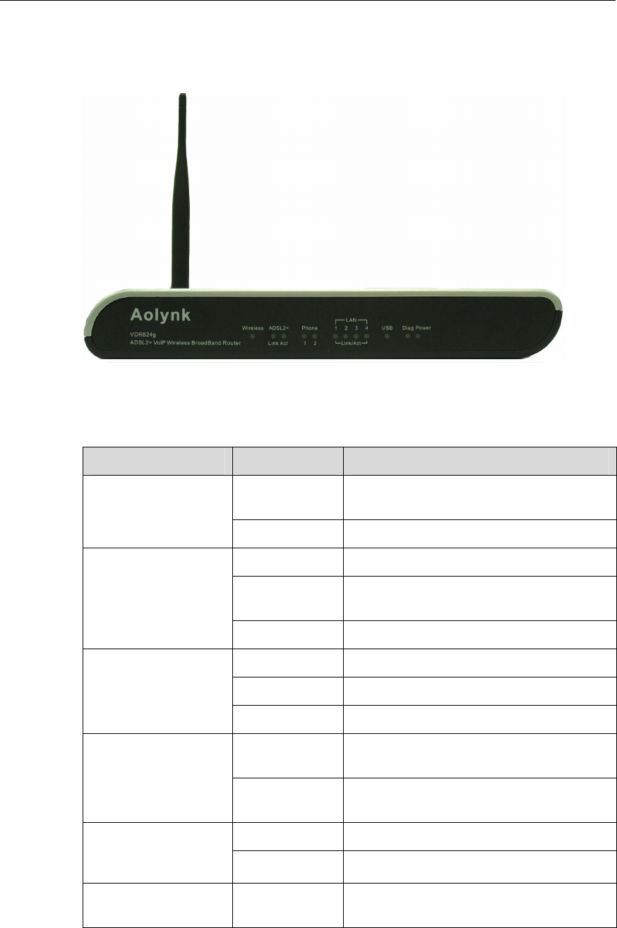
1.2.1 Front Panel
The LEDs on the front panel indicate the state of the VDR824/824g.
Figure 1- t view
Table 1-1 LED state description of the VDR
1 Fron
824/824g
LED State Description
ON The power is ON and the oper
normal. ation is
Power
OFF The power is off or fault occurs.
ON The Ethernet link is established.
Blinking ted and received on Data is being transmit
the Ethernet port.
LAN1/2/3/4
OFF No link is present.
ON The ADSL link is up.
Blinking The ADSL link is starting up.
ADSL2+ Link
OFF The ADSL link is down.
Blinking s being transmitted and received on Data i
the ADSL link.
ADSL2+ Act
OFF No data transmission is present
link. on the
ON The wireless function is enabled. Wireless (This is not
available on the sabled
VDR824.) OFF The wireless function is di
Phone 1/2 ON The telephone is off-hook or in
conversation.
User Manual
Aolynk VDR824 ADSL2+ VoIP Broadband Router/
Aolynk VDR824g ADSL2+ VoIP Wireless Broadband Router 1 Product Overview
3
LED State Description
Blinking The telephone is ringing.
to the
telephone or the telephone is on-hook.
OFF The port is not connected
ON The USB connection is established.
USB OFF No USB connection is present.
Diag — For manufactory test only.
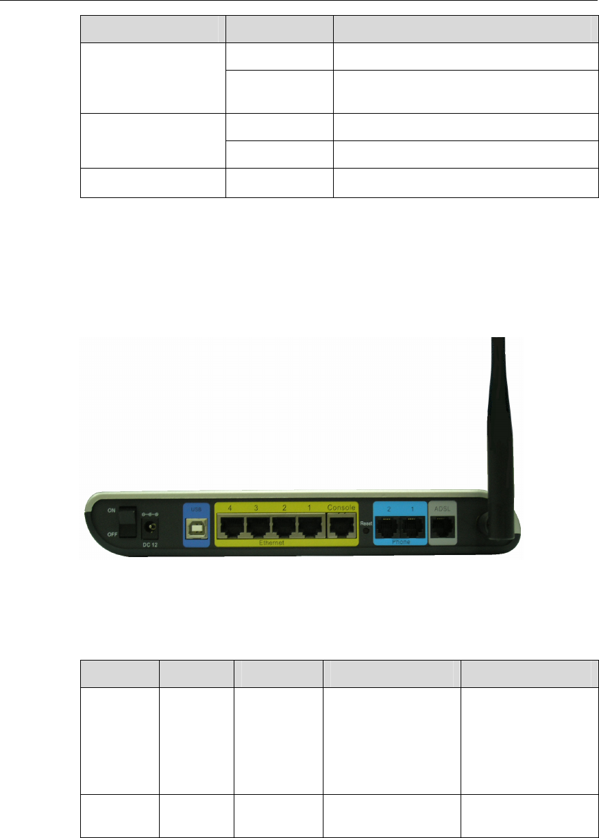
1.2.2 Rear Panel
d on the rear All ports of the VDR824/824g, a power port, and a reset button are locate
panel.
Figure 1-2 Rear view
Table 1-2 Description of the ports and re ear panel of the
VDR824/824g
set button on the r
Item Quantity Port Description Usage
Ethernet 10/100 Mbps
auto-MDI/MDIX
IEEE802.3/802.3u
port 4 RJ45
10/100Base-TX
auto-negotiation Connect with the
Ethernet port of a
PC, Hub or switch.
USB port 1 Series-B
Receptacle USB 1.1 Connect with the
USB port of a PC.

User Manual
Aolynk VDR824 ADSL2+ VoIP Broadband Router/
Aolynk VDR824g ADSL2+ VoIP Wireless Broadband Router 1 Product Overview
4
Item Quantity Port Description Usage
ADSL port 1 RJ11
ANSI T1.413 Issue
2
ITU G.992.1
AnnexA G.dmt
ITU G.992.2 G.lite
ITU G.992.3 ADSL2
ITU G.992.5
ADSL2+
Connect with the
telephone jack on
the wall or the ADSL
port of a splitter.
Phone
port 2 RJ11
— Connect with the
common telephone
to place IP calls.
Power
port 1 — — Connect with the
power adapter.
Reset
button 1 — —
Restore factory
default settings
(press and hold
down the button for
at least five
seconds).
1.3 Features
Both VDR824 and VDR824g perform excellent network connection. Both have the
following features:
z Asymmetrical data transmission technology with downstream speed of 20 Mbps
and upstream speed of 1 Mbps.
z SIP protocol that enables you to place IP calls by connecting the common
telephone to the phone port of the VDR824/824g.
z Binding of an Ethernet port to a PVC, which enables you to access Internet
services through different LAN ports.
z NAT (network address translation) technology that allows all PCs on a network to
access the Internet sharing a single IP address.
z PPPoE dialup connection to the ISP.
z Capability of a DHCP (dynamic host configuration protocol) client to obtain a fixed
IP address from an ISP or a dynamically assigned IP address.
z Capability of a DHCP server to assign IP addresses to hosts in a LAN or configure
clients through the DHCP server.
z DNS relay that allows you to specify the IP address of an Ethernet port on the
VDR824/824g as a DNS server IP address of a PC.
z DHCP relay that allows one DHCP server available for multiple DHCP clients in
different network segments.

User Manual
Aolynk VDR824 ADSL2+ VoIP Broadband Router/
Aolynk VDR824g ADSL2+ VoIP Wireless Broadband Router 1 Product Overview
5
z ZIPB (zero installation PPP bridge), NAT, firewall, and IP filtering that secure your
LAN.
z UPnP (Universal plug-and-play) for LAN users to use all the functions provided by
UPnP-supported software (such as MSN) without any further configuration.
z IP routing, DNS (domain name system) configuration, and the services such as
the IP and DSL performance monitoring.
z Friendly built-in Web-based graphical user interface for ease of configuration and
management through common Web browsers.
Besides, the VDR824g also has the following wireless features:
z The bridge from wireless to wired enabling Ethernet LAN and wireless LAN users
to transmit data from each other.
z 64/128 bit WEP encryption to ensure the security of the wireless communication.
z Full support of 802.11 public and shared key authentication.
User Manual
Aolynk VDR824 ADSL2+ VoIP Broadband Router/
Aolynk VDR824g ADSL2+ VoIP Wireless Broadband Router 2 Installation
6
2 Installation
On the assumption that you have acquired DSL services from your ISP, the following
e how to set up the VDR824/824g and configure your PC.
2.1 Pac
rton carefully and check the following items listed in Table 2-1.
Table 2-1 Packing list
sections describ
king List
Unpack the shipping ca
Item Quantity
Aolynk VDR824/824g ADSL2+ VoIP Router 1
Power adapter 1
Telephone cable 1
Straight-through cable 1
USB cable 1
Set of screw and anchor 2
Aolynk VDR824/824g ADSL2+ VoIP Router Quick Start 1
CD including the user manual and driver 1
Warranty Card 1
Certificate of Quality 1
roken or missing, contact your agent for help.
2.2 Prec
g
shou quirements described below:
If anything is b
autions
To uarantee normal operation and longevity of the VDR824/824g, its installation site
ld meet the re
z Use the VDR824/824g indoors and keep it far away from the heat sources and
water/liquid.
User Manual
Aolynk VDR824 ADSL2+ VoIP Broadband Router/
Aolynk VDR824g ADSL2+ VoIP Wireless Broadband Router 2 Installation
7
wer adapter well on the wall when wall-mounting it.
nication failure.
z ble indoors. Outdoor cabling is prohibited, to prevent the signal
port from damages that may be caused by overvoltage and overcurrent from
z Keep the cabinet or desk stable enough to hold the VDR824/824g. Fix the
VDR824/824g and po
z Reserve more than 10 cm (4 in.) of clearance around the VDR824/824g chassis
for heat dissipation.
z Keep the operation environment clean. Dust buildup on the chassis may result in
static absorption, reducing the life span and causing commu
z Use an earthing system or lightning protection grounding different from that for the
power supply equipment and keep them as far as possible.
z Keep the VDR824/824g far away from high-power radio launchers, radar
launchers, and equipment with high-frequency and high-current.
Wire the port ca
lightning strike.
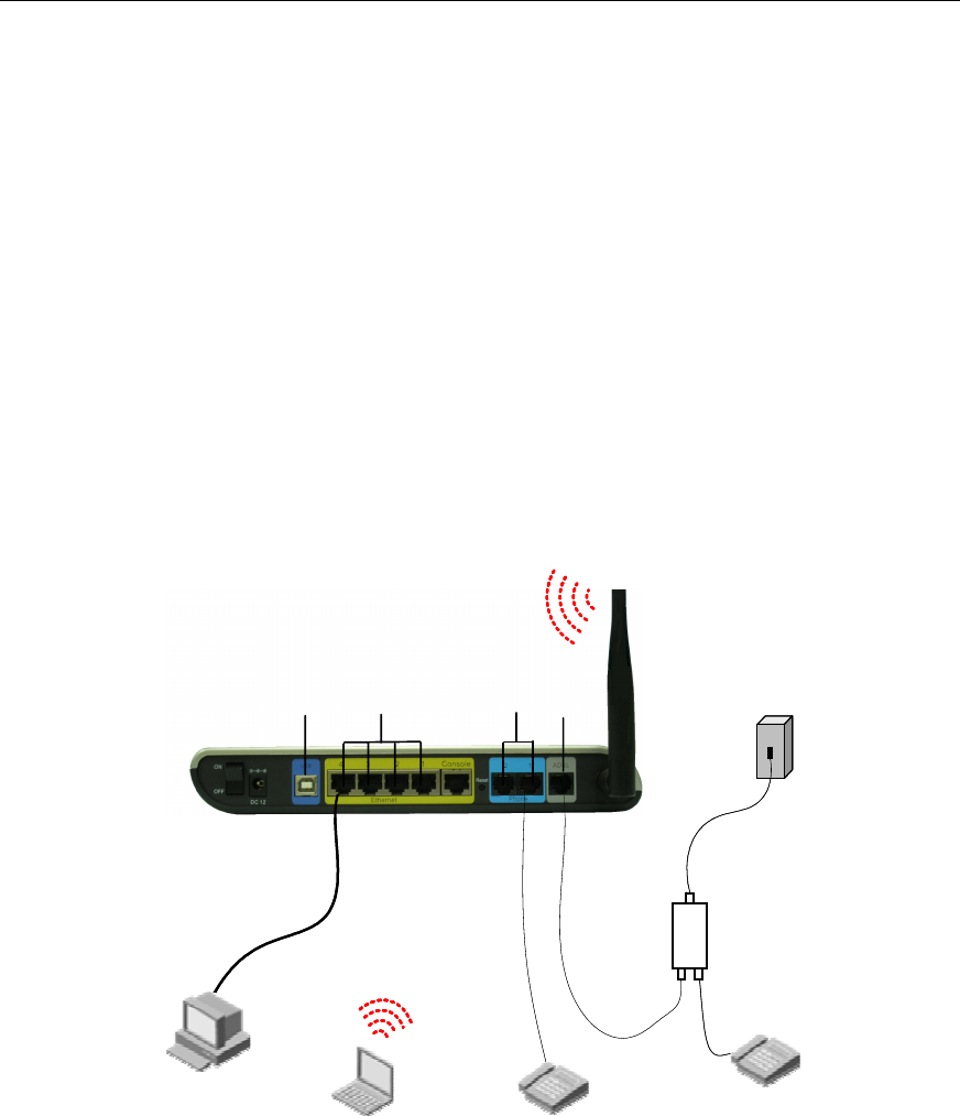
2.3 Device Connection
Telephone
PC
Telephone jack
Notebook
Splitter
Line
ADSL Phone
LAN
USB ADSL
VDR824g
Telephone
Phone
Telephone
PC
Telephone jack
Notebook
Splitter
Line
ADSL Phone
LAN
USB ADSL
VDR824g
Telephone
Phone
824/824g
I.
To c
z phone cable to the ADSL port (similar to a common
Figure 2-1 Connect the VDR
Connect to an ADSL line
onnect the VDR824/824g to an ADSL line, two options are available:
Connect one end of the tele
telephone port) on the VDR824/824g rear panel, and the other end to the
telephone jack on the wall.
User Manual
Aolynk VDR824 ADSL2+ VoIP Broadband Router/
Aolynk VDR824g ADSL2+ VoIP Wireless Broadband Router 2 Installation
8
ect both the ADSL port on the VDR824/824g and the
e
II. Con
To c :
z
Ethernet port (one among LAN1 through LAN4) of the VDR824/824g.
Connect your PC to the VDR824/824g through the USB ports with a USB cable. It
or the PC without NIC to access the Internet.
z As shown in Figure 2-1, conn
telephone to a splitter, and then connect the splitter to the telephone jack on th
wall. It allows you to use the telephone when you access the network.
nect to a PC or Ethernet
onnect the VDR824/824g to a PC or Ethernet, two options are available
The Ethernet ports of the VDR824/824g are auto-MDI/MDIX, so you can use the
crossover or straight-through cable to connect your PC, Hub, or switch to the
z
is suitable f
Caution:
T
config
o use the USB port on the VDR824/824g, you must install the USB driver and
ure your PC (refer to section 8 “Appendix - USB Configuration” for detailed
information).
I. Connect to the telephone II
e telephone with Phone 1 on the rear panel of the
IV
nd of the power adapter to the VDR824/824g and the other end to the
the VDR824/824g.Approximately one minute
after wer-on, the f the LEDs on the front e those listed in
Table 2-2.
Table 2-2 Description of the LED states
Use the telephone cable to connect th
VDR824/824g. If both Phone 1 and Phone 2 are assigned with the registration
accounts, connect another telephone with Phone 2.
. Connect to the power adapter
Attach one e
power outlet. Then turn on the power of
the po states o panel should b
LED State Description
Power Green —
Link Green —
Blinking Data is being transmitted and received.
Act ission is present.
OFF No data transm

User Manual
Aolynk VDR824 ADSL2+ VoIP Broadband Router/
Aolynk VDR824g ADSL2+ VoIP Wireless Broadband Router 2 Installation
9
LED State Description
Green The Ethernet link is established.
LAN Blinking Data is being transmitted and received on the
Ethernet port.

User Manual
Aolynk VDR824 ADSL2+ VoIP Broadband Router/
Aolynk VDR824g ADSL2+ VoIP Wireless Broadband Router 3 Getting Started
10
Getting Started
nfiguration pages as the way to manage it.
ed. This chapter guides you to be familiar
pages.
3.1 Prer
eb pages, you must configure your
later)
rk segment as
n page. The default IP address of
the VDR824/824g Ethernet port is 192.168.1.1. Refer to section 7 “Appendix - TCP/IP
Protocol”.
III. No proxy server
If your PC uses the proxy server to access the Internet, you must disable the proxy
1) Choose [Tool/Internet options] to open the [Internet options] window.
3.2 Log
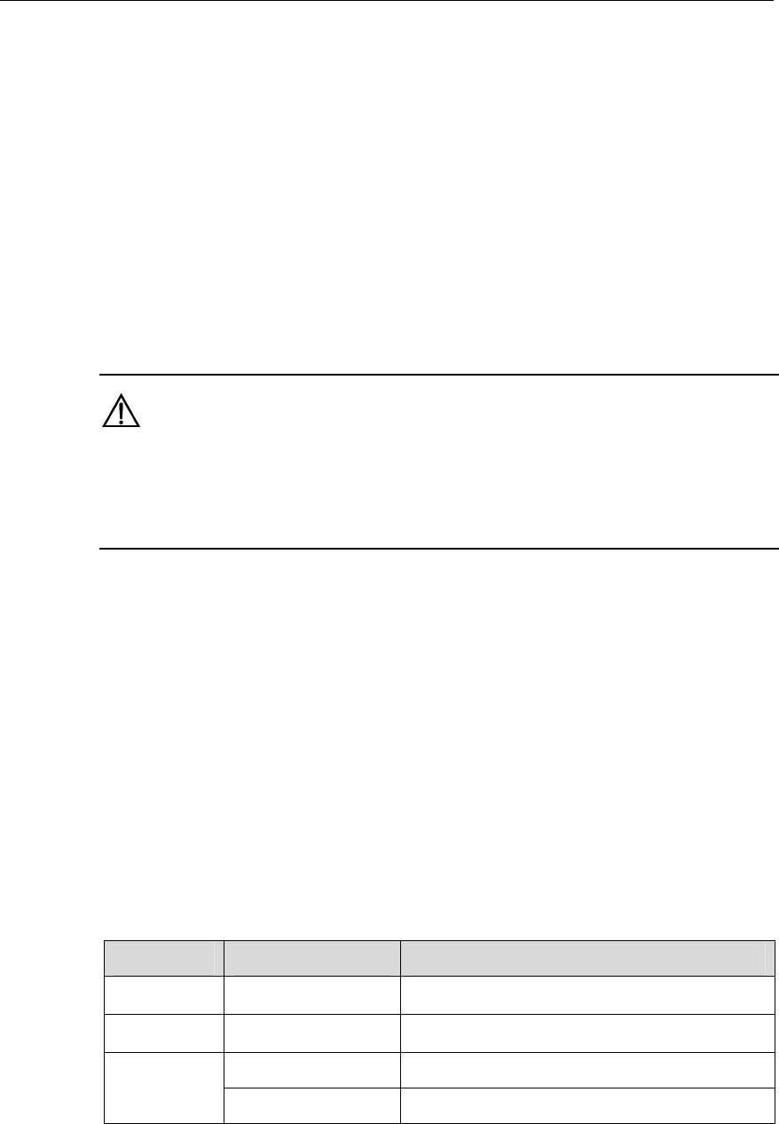
un your Web browser and enter http://192.168.1.1 in the address bar. A login dialog
box appears as shown in Figure 3-1.
3
The VDR824/824g offers a series of Web co
You can configure the VDR824/824g as need
with the Web configuration
equisite Tasks for Configuration
To configure the VDR824/824g through its built-in W
PC as the following.
I. System requirements
z An Ethernet NIC (10Base-T or 10/100Base-T/TX) or a USB port
z A Web browser (Microsoft Internet Explorer 5.5, Netscape 6.0 or
z TCP/IP protocol employed
II. IP address of your PC
You must assign an IP address to your PC to make it in the same netwo
the VDR824/824g before accessing the configuratio
service.
2) Select the [Connections] tab and click <LAN settings…>.
3) Make sure the Use a proxy server option is not selected.
in
R
User Manual
Aolynk VDR824 ADSL2+ VoIP Broadband Router/
Aolynk VDR824g ADSL2+ VoIP Wireless Broadband Router 3 Getting Started
11
adminadmin
Figure 3-1 Login dialog box
For the first login, type in the default user name admin and password admin, and then
click <OK> to enter the Web configuration page.
Navi
Setup
gation bar Title
section
Navi
Setup
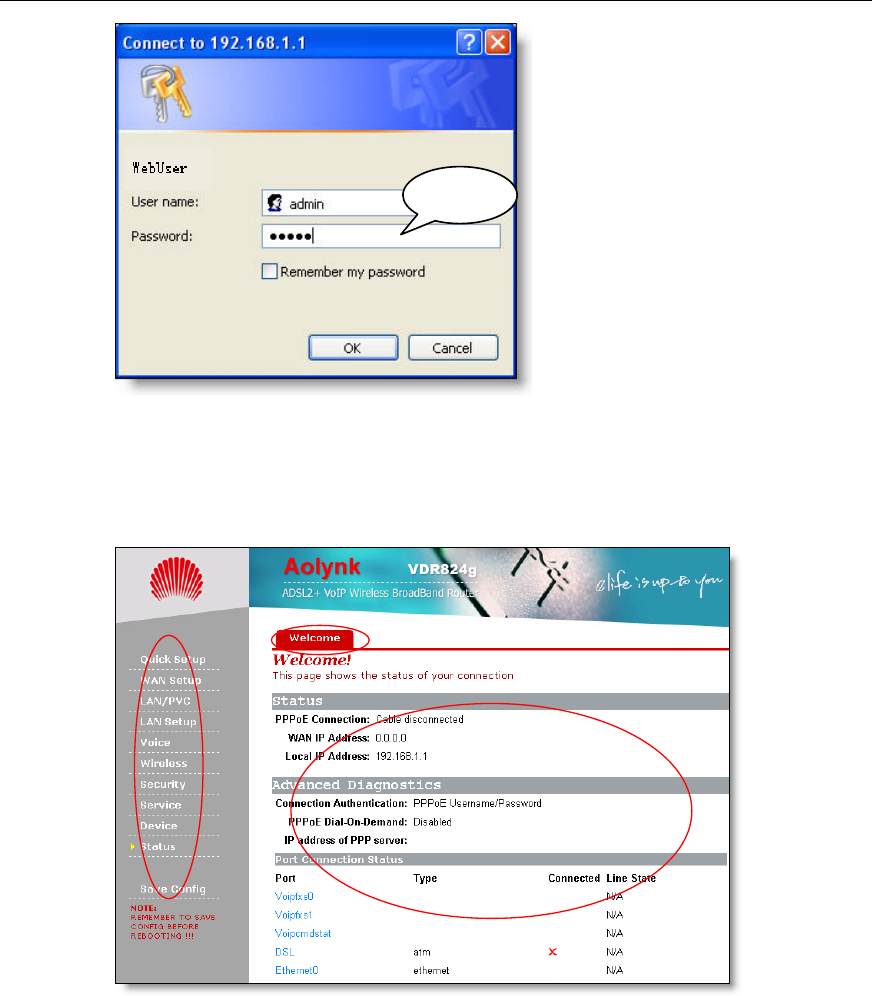
F
T nfiguration
bar, Title, and Setup section. Navigation bar p and
management part is on the right pane where y
st vigation bar or
c e p sectio
gation bar Title
section
24g consists of three parts: Navigation
is on the left pane, and the setu
igure 3-2 Welcome pa
he Web co
ge
page of the VDR824/8
ou can configure and display the device
a tab from the title, the corresponding
n.
atus. Click a link in the na
onfiguration page app ars in the setu

User Manual
Aolynk VDR824 ADSL2+ VoIP Broadband Router/
Aolynk VDR824g ADSL2+ VoIP Wireless Broadband Router 3 Getting Started
12
Note:
ze the logi refer to
information.
If you receive an error message or the configuration page cannot be displayed, refer
to section 6.1 “VDR824/824g Troubleshooting” for detailed instructions.
To chang n password, section 4.6.1 “Password” for detailed
z
3.3 Description of the Factory Default Settings
The VDR824/824g is configured with factory default settings for SOHO users.
The table below lists some of the most important default settings and the subsequent
chapters will cover all the features in detail. If you are familiar with network
configuration, review these settings to verify that they meet the requirements of your
network and follow the instructions to change them if necessary. If not, use the
VDR824/824g with the default settings.
Table 3-1 Description of the factory default settings
Item Default settings Description
Default user
name/password
Administrator:
admin/admin
Common user:
user/user
You can log into the Web configuration
page as an administrator or a common
user. Different operation rights are
available for different login users.
Refer to 4.6.1 “Password” for detailed
information.
IP address of the
LAN port
Assigned static IP
address:
192.168.1.1
Subnet mask:
255.255.255.0
This is the IP address of the
VDR824/824g LAN port which
connects the VDR824/824g to your
Ethernet network. Generally, there is
no need to change this address.
DHCP
(dynamic host
configuration
protocol)
DHCP server
enabled with the
following pool of
addresses:
192.168.1.2 to
192.168.1.51
The VDR824/824g provides a pool of
private IP addresses for dynamic
assignment to PCs in the LAN. To use
this service, you must configure your
PC to obtain an IP address
dynamically. Refer to section 7.2.1
“Specifying to Obtain an IP Address
Automatically”.
NAT (network
address translation) NAT enabled
Your PC’s private IP address is
translated to the public IP address
whenever it accesses the Internet.
Refer to section 5.2.1 IV. “NAT
configuration” for detailed information.

User Manual
Aolynk VDR824 ADSL2+ VoIP Broadband Router/
Aolynk VDR824g ADSL2+ VoIP Wireless Broadband Router 3 Getting Started
13
Item Default settings Description
DSL mode Multimode Applicable to multiple standard DSL
line modes.
User Manual
Aolynk VDR824 ADSL2+ VoIP Broadband Router/
Aolynk VDR824g ADSL2+ VoIP Wireless Broadband Router 4 Web-based Basic Configuration
14
4
HO
4.1 Quick Setup
I. PPPoE
Web-based Basic Configuration
This chapter describes the basic configuration pages of the VDR824/824g for SO
users to implement its basic functions. For details of advanced configuration, refer to
section 5 “Advanced Configuration”.
Click [Quick Setup] in the navigation bar to enter the [Quick Start] page on which you
can perform some simple settings to access the Internet quickly. Here, two common
login types are available: PPPoE and DHCP.
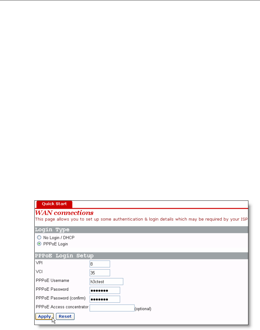
lt login type on the page is PPPoE. This type requires you to type in the VPI
and VCI values, PPPoE user name and PPPoE password specified by your ISP, and
repeat the password for confirmation in the [PPPoE Password (confirm)] text box.
Figure 4-1 Quick Setup – PPPoE Login
The defau
User Manual
Aolynk VDR824 ADSL2+ VoIP Broadband Router/
Aolynk VDR824g ADSL2+ VoIP Wireless Broadband Router 4 Web-based Basic Configuration
15
E When there are multiple PPPoE servers in the network, you can specify the PPPo
server identifier through which the PPPoE client accesses in the [PPPoE Access
concentrator] text box.
Click <Apply> after the configuration is complete.
II. DHCP
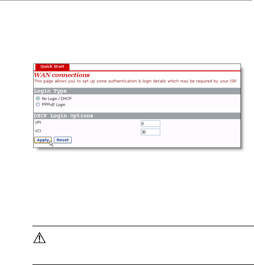
Figure 4-2 Quick Setup – No Login/DHCP
ally, select the
and type in the VPI
If you can obtain IP addresses from your ISP’s DHCP server automatic
No Login/DHCP option on the [Quick Start] page (see Figure 4-1)
and VCI values specified by your ISP on the page (see Figure 4-2).
Click <Apply> after the configuration is complete.
Caution:
Do not set the same VPI and VCI values for DHCP and PPPoE login types.
AN Setup 4.2 W
Click [WAN Setup] in the navigation bar to enter the corresponding page which three
Relay, and DDNS. Click the desired tab to enter its
configuration page.
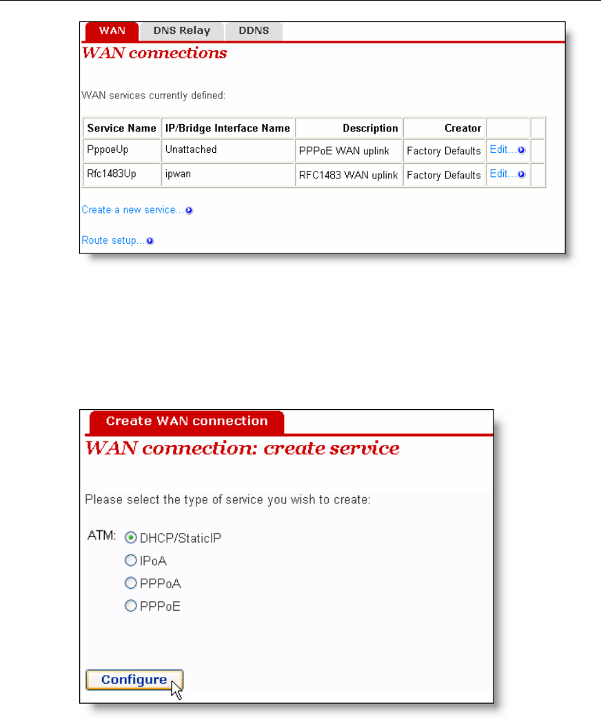
4.2.1 WAN
set WAN connections in detail, or to modify the service
on
tabs are available: WAN, DNS
This page allows you to
attributes. You can access the Internet normally only when these attributes are set
correctly.
User Manual
Aolynk VDR824 ADSL2+ VoIP Broadband Router/
Aolynk VDR824g ADSL2+ VoIP Wireless Broadband Router 4 Web-based Basic Configuration
16
Figure 4-3 WAN
Create a new service
To create a new service, click <Create a new service…> to enter the [WAN connectio
create service] page (see Figure 4-4).
I.
n:
service FCreate a WAN
This p and
P owing int
1
The IP address in this m e manually specified or automatically assigned by
our ISP. The former requires you to manually specify the DNS server address on the
[DNS Relay] page. For details, refer to section 4.2.2 “DNS Relay”.
igure 4-4
age provides four modes for
PPoE. The foll
WAN connection: DHCP/StaticIP, IPoA, PPPoA
roduces their configurations respectively.
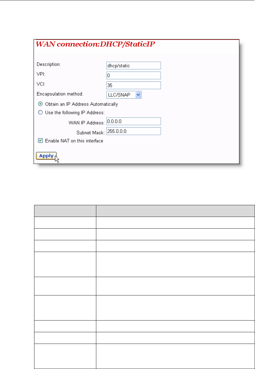
) DHCP/Static IP
ode can b
y
User Manual
Aolynk VDR824 ADSL2+ VoIP Broadband Router/
Aolynk VDR824g ADSL2+ VoIP Wireless Broadband Router 4 Web-based Basic Configuration
17
t the DHCP/StaticIP option from the
st (see Figure 4-4), and then click <Configure> to enter the page (see
To create a DHCP/Static IP WAN connection, selec
ATM mode li
Figure 4-5).
Figure 4-5 DHCP/Static IP
Table 4-1 Description of the DHCP/Static IP items
Item Description
Descriptio Type in the distinctive de this service.
n scription on
VPI Type in the VPI value provided by your ISP.
VCI Type in the VCI value provided by your ISP.
Encapsulation ng to your
method
Select the packet encapsulation method accordi
ISP, LLC/SNAP or VcMux, from the drop-down lastly/SNAP
is usually selected.
Obtain an IP Address btain an IP address from your ISP’s
Automatically Select this option to o
DHCP server automatically.
Use the following IP ss provided
Address
Select this option if you have the static IP addre
by your ISP. You need also provide the IP address and
subnet mask.
WAN IP Address e static IP address provided by your ISP.
Type in th
Subnet Mask Type in the subnet mask provided by your ISP.
Enable NAT on this Select this check box to
interface
enable NAT. With it, SOHO users
can make multiple hosts access network via a public IP
address.
User Manual
Aolynk VDR824 ADSL2+ VoIP Broadband Router/
Aolynk VDR824g ADSL2+ VoIP Wireless Broadband Router 4 Web-based Basic Configuration
18
rate.
st (see
Click <Apply> after the configuration is complete.
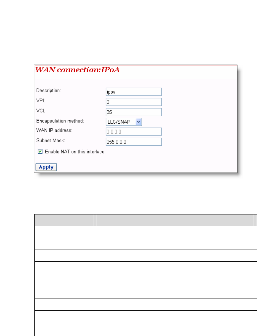
2) IPoA
IPoA allows IP packets directly over the ADSL physical link at high transmission
To create an IPoA WAN connection, select the IPoA option from the ATM mode li
Figure 4-4), and then click <Configure> to enter the page as below.
FA
Table 4-2 Description o
igure 4-6 IPo
f the IPoA items
Item Description
Description Type in the distinctive description on this service.
VPI Type in the VPI value provided by your ISP.
VCI Type in the VCI value provided by your ISP.
Encapsulation
method
to your Select the packet encapsulation method according
ISP, LLC/SNAP or VcMux, from the drop-down lastly/SNAP
is usually selected.
WAN IP Address Type in the static IP address provided by your ISP.
Subnet Mask Type in the subnet mask provided by your ISP.
Enable NAT on this
interface
Select this check box to enable NAT. With it, SOHO users
can make multiple hosts access network via a public IP
address.
Click <Apply> after the configuration is complete.
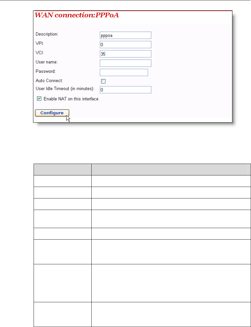
3) PPPoA
To create a PPPoA WAN connection, select the PPPoA option from the ATM mode list
(see Figure 4-4), and then click <Configure> to enter the page as below.
User Manual
Aolynk VDR824 ADSL2+ VoIP Broadband Router/
Aolynk VDR824g ADSL2+ VoIP Wireless Broadband Router 4 Web-based Basic Configuration
19
Figure 4-7 PPPoA
Table 4-3 Description of PPPoA items
Item Description
Description Type in the distinctive description on this service.
VPI Type in the VPI value provided by your ISP.
VCI Type in the VCI value provided by your ISP.
User nameUser
name Type in the user name provided by your ISP.
Password Type in the password provided by your ISP.
Auto Connect o a LAN
If this check box is selected, the device automatically
performs the dialup connection again in response t
access request when the network is disconnected.
User Idle Timeout to 0, it
Type in the auto-disconnect idle time. Network connection is
disconnected automatically in the case of no data
transmission within the set time. This is suitable for
time-based network accounting. If the time is set
indicates that the connection is never disconnected.
Enable NAT on this
interface multiple hosts access network via a public IP
address.
Select this check box to enable NAT. With it, SOHO users
can make
Click <Configure> after the configuration is complete.
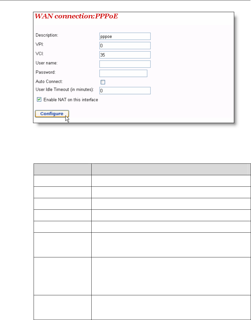
4) PPPoE
To create a PPPoA WAN connection, select the PPPoA option from the ATM mode list
(see Figure 4-4), and then click <Configure> to enter the page as below.
User Manual
Aolynk VDR824 ADSL2+ VoIP Broadband Router/
Aolynk VDR824g ADSL2+ VoIP Wireless Broadband Router 4 Web-based Basic Configuration
20
Figure 4-8 PPPoE
Table 4-4 Description of PPPoE items
Item Description
Description Type in the distinctive description on this service.
VPI Type in the VPI value provided by your ISP.
VCI Type in the VCI value provided by your ISP.
User name Type in the user name provided by your ISP.
Password Type in the password provided by your ISP.
Auto Connect If this check box is selected, the device automatically
performs the dialup connection again in response to a LAN
ss request when the network is disconnected.
acce
User Idle Timeout disconnected automatically in the case of no data
transmission within the
time-based network accou
Type in the auto-disconnect idle time. Network connection is
set time. This is suitable for
nting. If the time is set to 0, it
indicates that the connection is never disconnected.
Enable NAT on this
interface
Select this check box to enable NAT. With it, SOHO users
can make multiple hosts access network via a public IP
address.
Click <Configure> after the configuration is complete.
User Manual
Aolynk VDR824 ADSL2+ VoIP Broadband Router/
Aolynk VDR824g ADSL2+ VoIP Wireless Broadband Router 4 Web-based Basic Configuration
21
Caution:
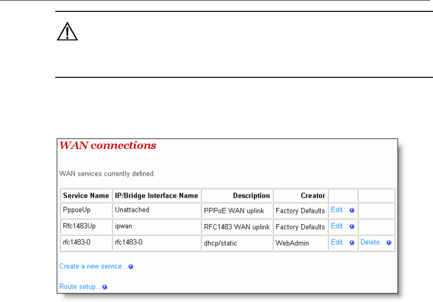
Do not set the same VPI and VCI values for all services.
As shown in Figure 4-9, the service set up successfully will be added into the
service list.
WAN
Figure 4-9 WAN service list
AN service
To modify a service or perform advanced configuration, click the corresponding
II service
II. Edit a W
<Edit…> to enter the page. If necessary, modify the related values and then click
<Change>.For details of the ATM Channel parameter configuration, refer to section 5.1
II. “QoS configuration”.
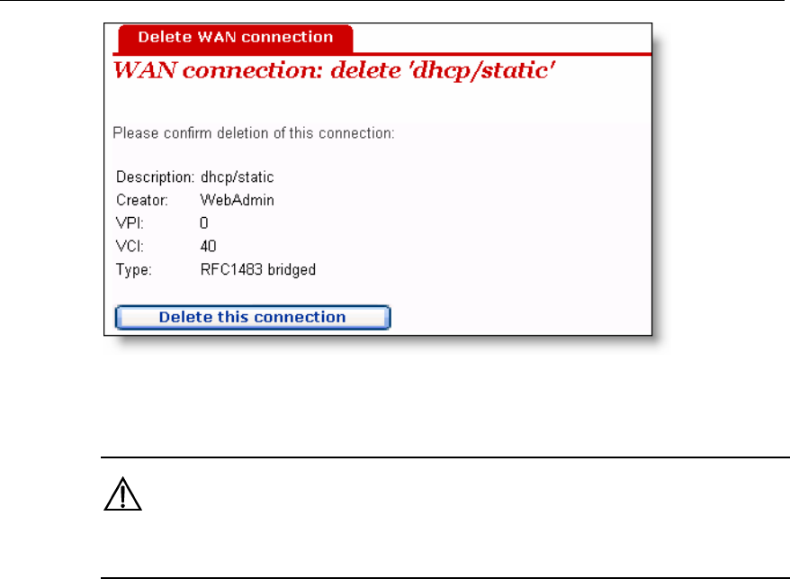
I. Delete a WAN
To delete an existing WAN service, click the corresponding <Delete…> button to enter
the page, and then click <Delete this connection>.
User Manual
Aolynk VDR824 ADSL2+ VoIP Broadband Router/
Aolynk VDR824g ADSL2+ VoIP Wireless Broadband Router 4 Web-based Basic Configuration
22
Figure 4-10 Delete a WAN connection
Caution:
The first two items in the WAN service list are default services and cannot be deleted.
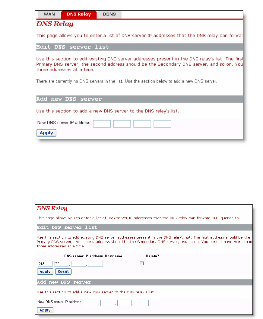
The VDR824/824g has the DNS relay function. Generally, the DNS server addre
obtained by your PC through DHCP is the IP address of the LAN port. You can also
specify the DNS server address on your PC as the IP address of the LAN port. The
VDR824/824g forwards the DNS query sent by your PC to the DNS server set on the
VDR824/824g.
The configuration pages below are used to set the DNS server list. The DNS query sen
by your PC is forwarded to the DNS server in the existing list. When your ISP change
the DNS server or you modify the connected ISP, there is no need to modify the IP
address of the DNS server on your PC.
4.2.2 DNS Relay
ss
t
s
User Manual
Aolynk VDR824 ADSL2+ VoIP Broadband Router/
Aolynk VDR824g ADSL2+ VoIP Wireless Broadband Router 4 Web-based Basic Configuration
23
Figure 4-11 DNS Relay (1)
To create a new DNS server, type in its IP address, suppose 218.72.1.1, in the [New
DNS server IP address] field, and then click <Apply>. This address will be added to the
list of the DNS server IP address (see Figure 4-12).
NS Relay (2)
Figure 4-12 D
User Manual
Aolynk VDR824 ADSL2+ VoIP Broadband Router/
Aolynk VDR824g ADSL2+ VoIP Wireless Broadband Router 4 Web-based Basic Configuration
24
Caution:
In the list of DNS server IP addresses, the first address should be for the primary DNS
server, the second for the secondary DNS server, and so on.
To modify the IP address of the DNS server in the list, modify it directly in the field and
then click <Apply>.
To delete the existing DNS server, select the corresponding [Delete?] check box and
then click <Apply>.
Dynamic Domain Name Service (DDNS). By way of PPPoE or static IP, the IP addr
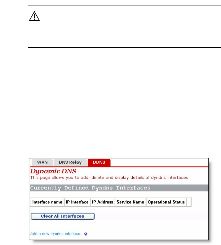
4.2.3 DDNS
ss
AN port obtained is unfixed, making it inconvenient for the Internet users to
problem. After you set the DDNS function,
the VDR824/824g update the mapping between the domain name and the IP address
o access the LAN through the domain name.
e
that the W
access the LAN server. DDNS solves this
automatically, ensuring the Internet users t
Figure 4-13 Dynamic DNS configuration (1)
Click <Add a new dyndns interface…> to enter the DDNS configuration page (see
Figure 4-14).
User Manual
Aolynk VDR824 ADSL2+ VoIP Broadband Router/
Aolynk VDR824g ADSL2+ VoIP Wireless Broadband Router 4 Web-based Basic Configuration
25
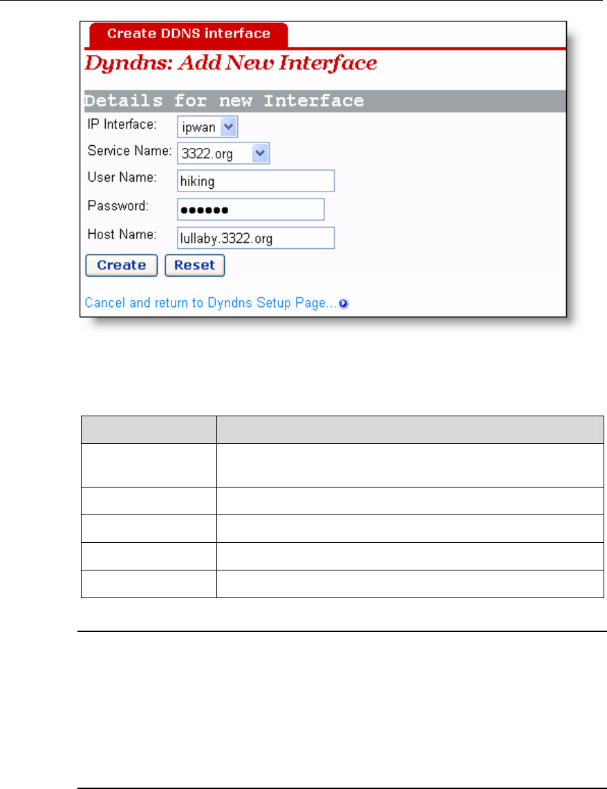
Figure 4-14 Dynamic DNS configuration (2)
Table 4-5 Description of the DDNS items
Item Description
IP interface Select the interface on which you want to enable the DDNS
function.
Service Name Select the web site where to obtain the DDNS service.
User Name Type in the user name you register with the DDNS server.
Password Type in the password you register with the DDNS server.
Host Name Type in the domain name you apply from the DDNS server.
Note:
As the client tool of the DDNS service, the DDNS function must cooperate with the
DDNS server. Visit www.3322.org, www.dyndns.org or www.tzo.com to apply for a
domain name before you enable the DDNS function. After you complete the DDNS
settings on the VDR824/824g, the mapping between the domain name and the IP
address of the WAN port is established.
Example: If you have applied for the domain name lullaby from www.3322.org, see
Figure 4-14 for the settings to make the mapping between the domain name and the IP
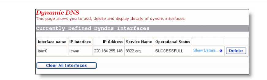
address of the WAN port on the VDR824/824g. Click <Create> and you can view the
DDNS configurations as below.
User Manual
Aolynk VDR824 ADSL2+ VoIP Broadband Router/
Aolynk VDR824g ADSL2+ VoIP Wireless Broadband Router 4 Web-based Basic Configuration
26
uration,
nt DDNS
e three
ter your
4.3.1 LAN
ttribute values for the Ethernet port and to configure virtual
interfaces.
Figure 4-15 DDNS configuration succeeds
To delete the DDNS configuration, click <Delete>. To clear all the DDNS config
click <Clear All Interfaces>. To view the detailed configuration of the curre
interface, click <Show Details…>.
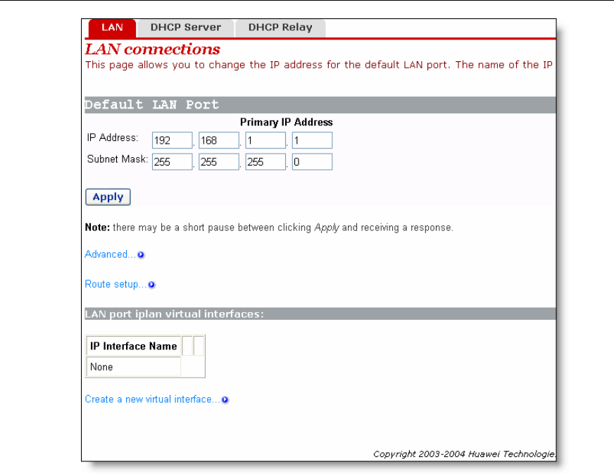
4.3 LAN Setup
Click [LAN Setup] in the navigation bar to enter the corresponding page wher
tabs are available: LAN, DHCP Server, and DHCP Relay. Click any tab to en
desired configuration page.
This page allows you to set a
User Manual
Aolynk VDR824 ADSL2+ VoIP Broadband Router/
Aolynk VDR824g ADSL2+ VoIP Wireless Broadband Router 4 Web-based Basic Configuration
27
I.
mask
to the
…> to
lues of
Figure 4-16 LAN connections
Set a LAN port
To change the IP address of the LAN port, type in the IP address and/or subnet
directly in the corresponding field, and then click <Apply>.For related introduction
IP address, refer to section 9 “Appendix - IP Address and Subnet Mask”
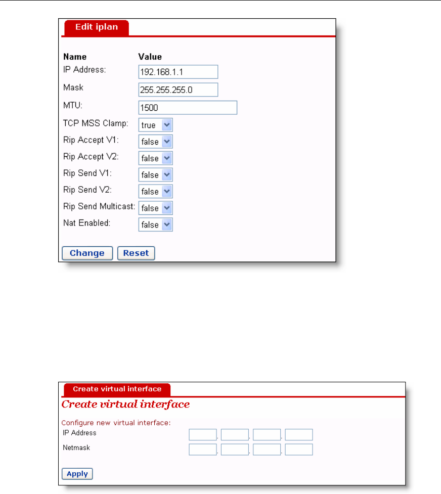
To perform advanced configuration on the attribute of LAN port, click <Advanced
enter the [Edit iplan] page as shown in Figure 4-17.If necessary, modify the va
options and click <Change>.
User Manual
Aolynk VDR824 ADSL2+ VoIP Broadband Router/
Aolynk VDR824g ADSL2+ VoIP Wireless Broadband Router 4 Web-based Basic Configuration
28
Modify the iplan interface
II
e [LAN
Figure 4-17
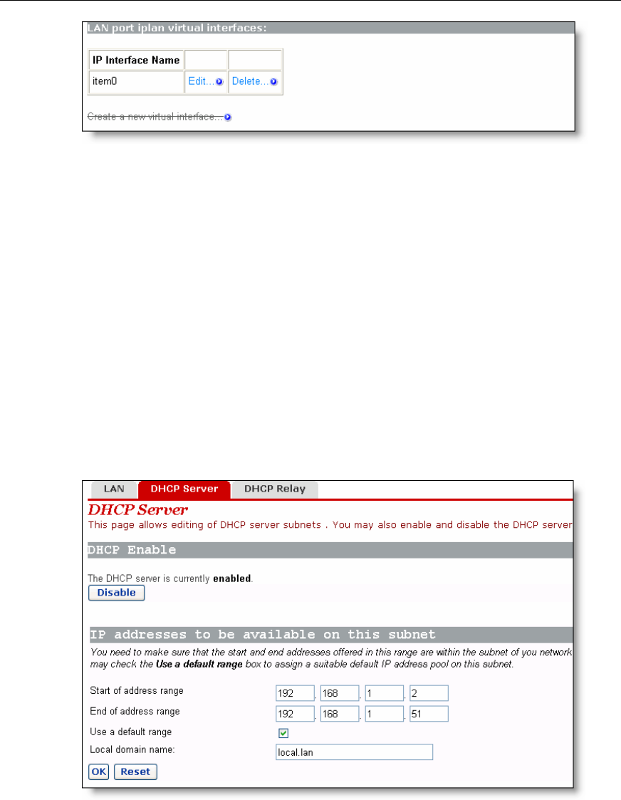
. Create a new virtual interface
To create a new virtual interface, click <Create a new virtual interface…> on th
connections] page (see Figure 4-16) to enter the page as below.
Figure 4-18 Create a virtual interface
Type in the IP address and subnet mask (you cannot configure the IP address
virtual interface and that of the LAN port to be in the same subnet) and click <A
of the
ply>.
ual interface is displayed on the page as below.
p
The information on this virt
User Manual
Aolynk VDR824 ADSL2+ VoIP Broadband Router/
Aolynk VDR824g ADSL2+ VoIP Wireless Broadband Router 4 Web-based Basic Configuration
29
ails, refer to
e current virtual interface, click the corresponding <Delete…> button to
enter the page, and then click <Delete this connection…>.
4.3.2 DHC
The VDR824/824g can act as a DHCP server to automatically assign IP addresses
within a certain range to any PC running in the LAN.
Figure 4-19 Virtual interface
The created virtual interface can be used for DMZ configuration. For det
section 5.3 "DMZ Configuration”.
To modify the information on the current virtual interface or perform advanced
configuration, click the corresponding <Edit…> button to enter the page. If necessary,
modify the values of options and click <Change>.
To delete th
P Server
Figure 4-20 DHCP Server
I. Enable/disable the DHCP server
If the DHCP server is disabled currently, you can click <Enable> to enable it.
Conversely, you can also click <Disable> to disable the DHCP server.

User Manual
Aolynk VDR824 ADSL2+ VoIP Broadband Router/
Aolynk VDR824g ADSL2+ VoIP Wireless Broadband Router 4 Web-based Basic Configuration
30
efined
nded
efault IP
do not
he start and
in the
e by entering
n also set
4.3.3 DHCP Relay
the DHCP
client on
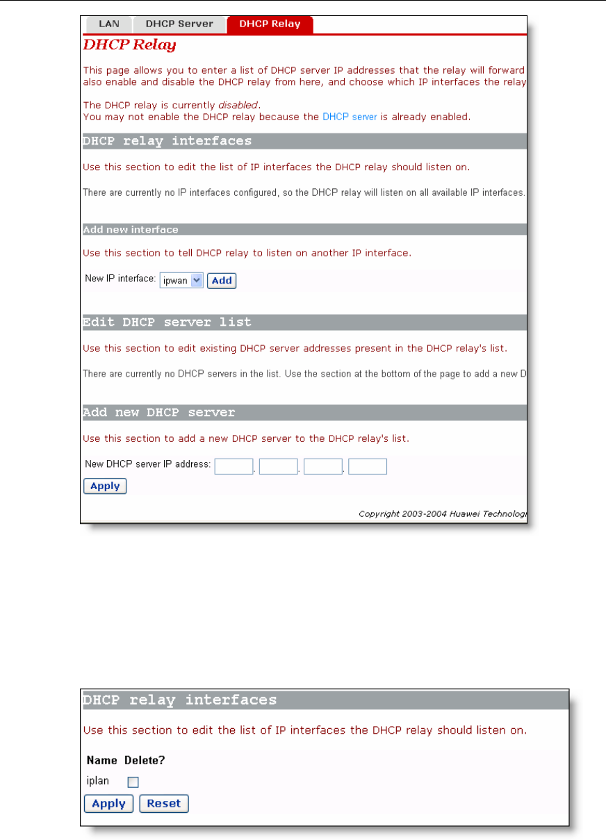
II. Set a DHCP server
The enabled DHCP server can assign the IP addresses, according to the d
address range on this page, to the DHCP client sending a request. It is recomme
that you select the [Use a default range] check box to assign a suitable d
address pool for the current subnet.
If necessary, you can also set the DHCP address range manually. In this case,
select the [Use a default range] check box (by removing the tick). Type in t
end IP addresses in the corresponding fields, and then click <OK>.
If necessary, you can type in commonly used DNS suffixes such as google.com
[Local domain name] text box. Thus, you can access the Google homepag
http://www/ in the Web browser. Small and medium-sized enterprises ca
their own DNS suffixes here while home users need not.
The VDR824/824g has the DHCP relay function to transmit packets between
client and server in different network segments, thereby making the DHCP
multiple networks use the DHCP server across these segments.
User Manual
Aolynk VDR824 ADSL2+ VoIP Broadband Router/
Aolynk VDR824g ADSL2+ VoIP Wireless Broadband Router 4 Web-based Basic Configuration
31
I. Specify a DHCP relay interface
On the [DHCP Relay] page (see Figure 4-21), select an interface (suppose iplan) from
rop-down list to apply the DHCP relay function, and then click
Figure 4-21 DHCP Relay page
the [New IP interface] d
<Add>. This interface will appear on the page as below.
Figure 4-22 New IP interface
User Manual
Aolynk VDR824 ADSL2+ VoIP Broadband Router/
Aolynk VDR824g ADSL2+ VoIP Wireless Broadband Router 4 Web-based Basic Configuration
32
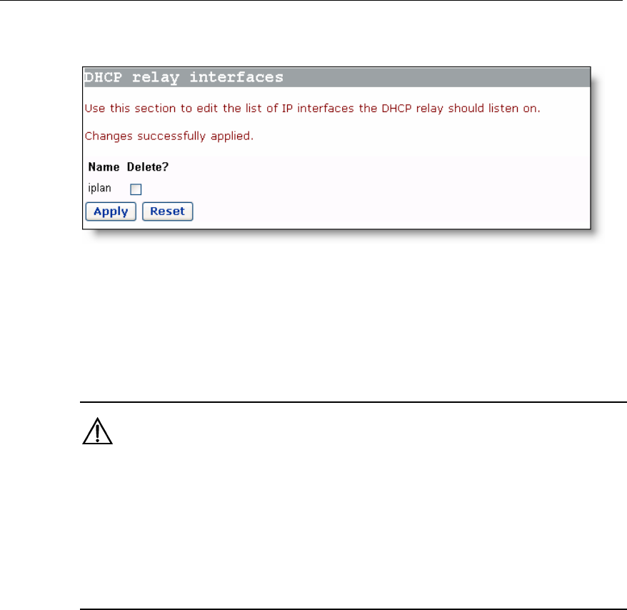
Click <Apply> in Figure 4-22 to apply this configuration, and the “Changes successfully
applied” information appear on the page as below.
o specify other interfaces.
Figure 4-23 The applied new IP interface
Follow the above instructions t
To delete this interface, select the corresponding [Delete?] check box and click
<Apply>.
Caution:
z
DHCP relay in pair. For example, to set the host connected to the LAN port to
communicate with the DHCP server on the WAN side, you need to configure the
iplan and ipwan to be the DHCP relay interfaces concurrently.
z If no interface is specified, the VDR824/824g enables the DHCP r
You should configure two interfaces (sending and receiving packets respectively) of
elay function on all
interfaces by default.
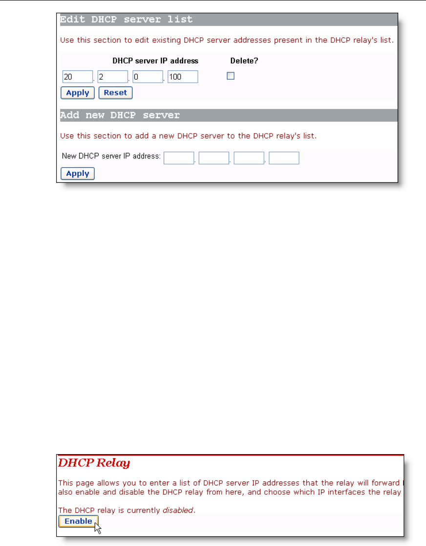
II. Set a DHCP server
ll be
To add a DHCP server, type in the IP address (suppose 20.2.0.100) of the DHCP server
in the [New DHCP server IP address] field (see Figure 4-21). This address wi
added to the list of DHCP server IP addresses as below.
User Manual
Aolynk VDR824 ADSL2+ VoIP Broadband Router/
Aolynk VDR824g ADSL2+ VoIP Wireless Broadband Router 4 Web-based Basic Configuration
33
ify the IP address of the DHCP server in the list, modify it directly in the field and
then click <Apply>.
DHCP server, select the corresponding [Delete?] check box and
II
nfiguration is complete. The
cannot be enabled
se the DHCP server
) to enter the DHCP server
Figure 4-25). If the
it. Conversely, click
Figure 4-24 Set a DHCP server
To mod
To delete the existing
then click <Apply>.
I. Enable/disable DHCP relay
You need to enable the DHCP relay function after the co
functions of DHCP server and DHCP relay of the VDR824/824g
concurrently. By default, you cannot enable the DHCP relay becau
is already enabled. The prompt is display as shown in Figure 4-21.
Click <DHCP Server> on the above page (see Figure 4-24
page, click <Disable> and thus <Enable> appears on the page (see
DHCP relay is disabled currently, you can click <Enable> to enable
<Disable> to disable it.
Figure 4-25 Enable/disable the DHCP relay
User Manual
Aolynk VDR824 ADSL2+ VoIP Broadband Router/
Aolynk VDR824g ADSL2+ VoIP Wireless Broadband Router 4 Web-based Basic Configuration
34
Caution:
T
spe rface and ce corresponding to the network where the DHCP
s
c te with the n interface, you must disable NAT
betwe al int
o ensure the DHCP
cified inte
relay to be effective, you need to disable NAT between the
the interfa
erver resides. For ex
ommunica
ample, to specify the host connected to the LAN port to
DHCP server on the ipwa
en the intern erface (iplan) and the external interface (ipwan).
4.4 Voic
C e nav are
available: Setting and SpeedDial. Click any tab to enter your desired configuration
age.
Setting
e
lick [Voice] in th igation bar to enter the corresponding page where two tabs
p
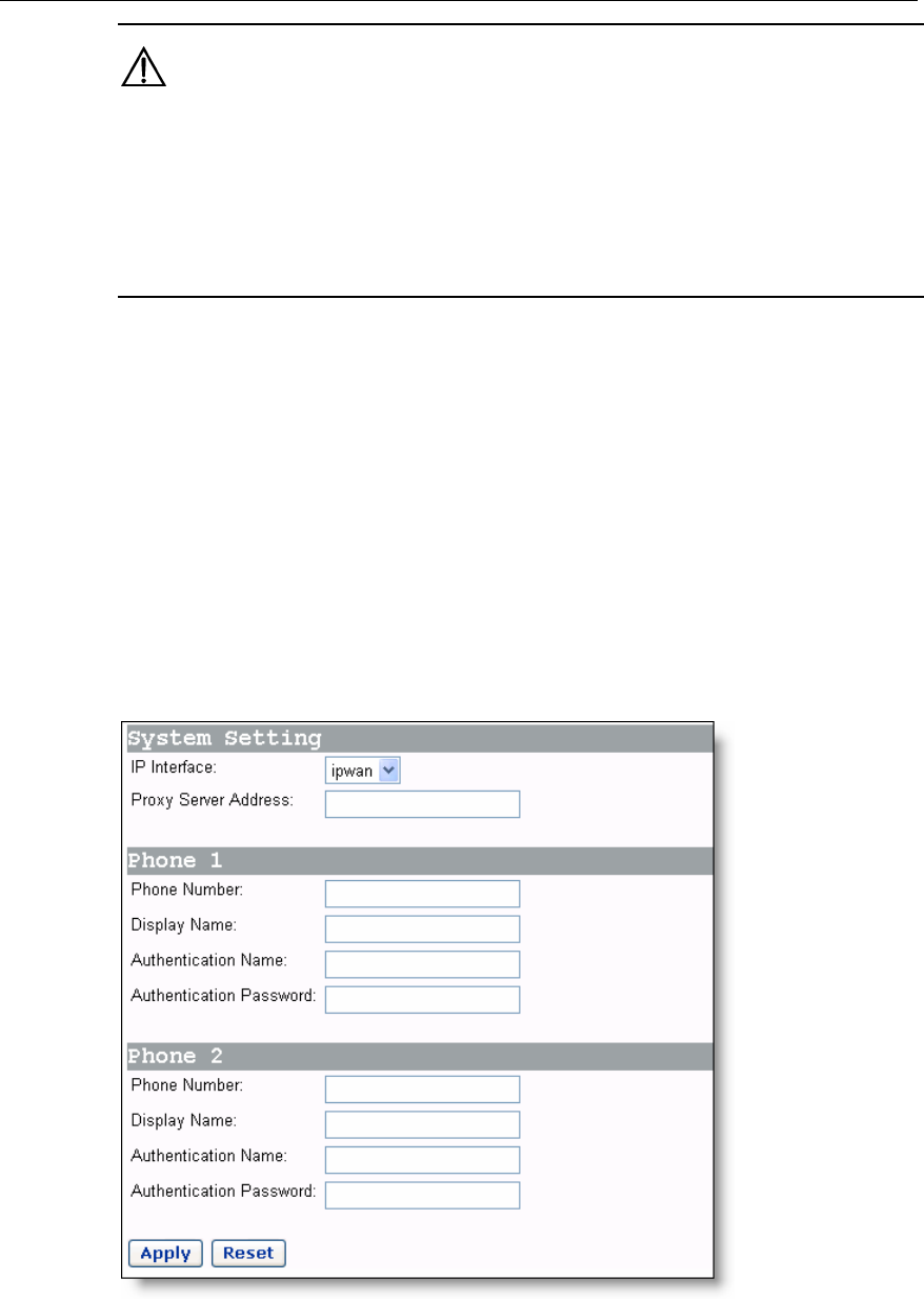
4.4.1 Phone Port
Before using the telephone connected to the VDR824/824g to place IP calls, you need
to set here the registration information about phone port provided by your ISP, and
register Phone 2 of the device with the SIP server.
rts Figure 4-26 Set the phone po
User Manual
Aolynk VDR824 ADSL2+ VoIP Broadband Router/
Aolynk VDR824g ADSL2+ VoIP Wireless Broadband Router 4 Web-based Basic Configuration
35
Table 4-6 Description of the phone port items
Item Description
IP interface Select the interface to which you want to bind the voice
function.
Proxy Server
Address Type in the IP address or domain name of the SIP server
provided by your SIP.
Display Name Optional. Set this item to display the name of the caller of the
an incoming call.
Phone Number Type in the telephone number provided by your ISP.
Authentication
Name Type in the authentication user name provided by your ISP.
Authenticatio
Password n
Type in the authentication password provided by your ISP.
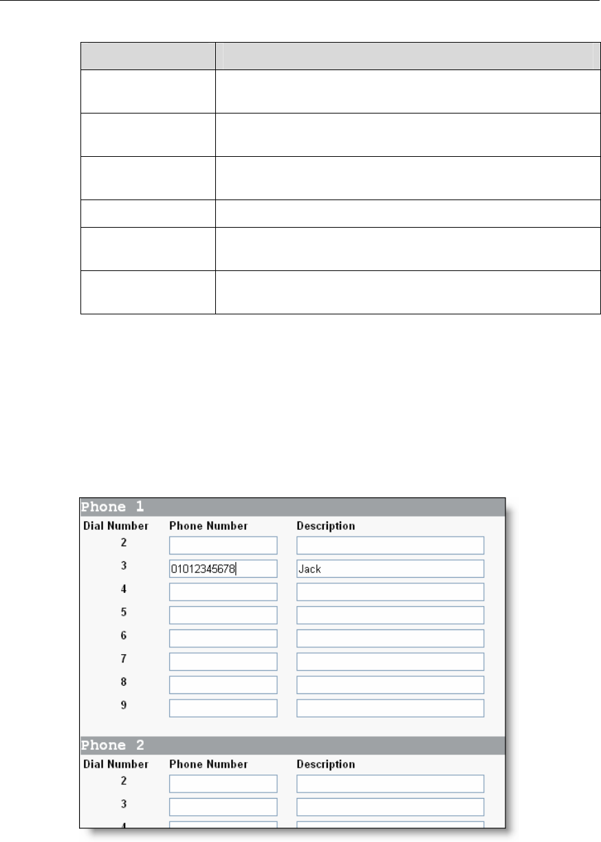
4.4.2 SpeedDial
4-27, the page is used to set the one-to-one relationship
between the number key and the telephone number.
The VDR824/824g supports the speed dial function. Press any number key from 2 to 9
(Key 1 is reserved for the system), you can dial out the corresponding telephone
number. As shown in Figure
Figure 4-27 Set the speed dial
The page includes the following items:
User Manual
Aolynk VDR824 ADSL2+ VoIP Broadband Router/
Aolynk VDR824g ADSL2+ VoIP Wireless Broadband Router 4 Web-based Basic Configuration
36
ponds to the phone number
xt to it.
z Number: Telephone number of a cont
z Description
t.
For example, af
connected to P
01012345678. C r the setting you have made.
4.5 Wireless
z Dial Number: Key number of the telephone. It corres
set ne
Phone act.
: Related information about the number, for example, name of the
ter the setting as shown in Figure 4-27 (suppose that the telephone is
hone 1), you can just press Key 3 to quickly call Jack’s number
lick <Apply> afte
contac
Note:
N fun
for the VDR824
o wireless ction is available on the VDR824. What describes in this section is only
g users.
C s] bar to enter the corresponding page where four tabs
ble: Basic, Security, Access and Advanced. Click any tab to enter your
esired configuration page.
lick [Wireles in the navigation
are availa
d
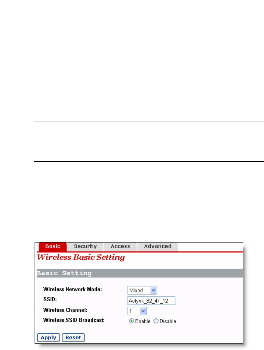
4.5.1 Wireless Basic Setting
This page allows you to set the basic wireless network parameters.
Figure 4-28 Wireless basic setting
User Manual
Aolynk VDR824 ADSL2+ VoIP Broadband Router/
Aolynk VDR824g ADSL2+ VoIP Wireless Broadband Router 4 Web-based Basic Configuration
37
-7 Description of the wireless basic setting items Table 4
Item Description
Wireless
Network
Select the wireless network mode from the drop-down list. If both
802.11g-based and 802.11b-based devices are available in your
network, keep the default Mixed option
802.11g-based device is available in your n
Mode
unchanged; if only the
etwork, select the G-Only
option; if only the 802.11b-based device is available in your network,
select the B-Only option. To disable the wireless network, select the
Disable option.
SSID Service set identifier, the unique identifier shared by the VDR824g
and other clients in the same wireless network. The SSID of all the
nodes must be the same and cannot exceed 32 characters.
Wireless
Channel
Select the appropriate wireless channel from the drop-down list. The
channel beyond the control range can be accepted. Ensure that the
nodes in the same wireless LAN use the same channel, or
automatically select the channel when clients are connected to the
access point.
Wireless
SSID
The wireless client detects the VDR824g SSID when searching for
the local accessible wireless network. To make the VDR824
broadcast the SSID, select the Enable option, otherwise, select the
ption.
g
Broadcast Disable o
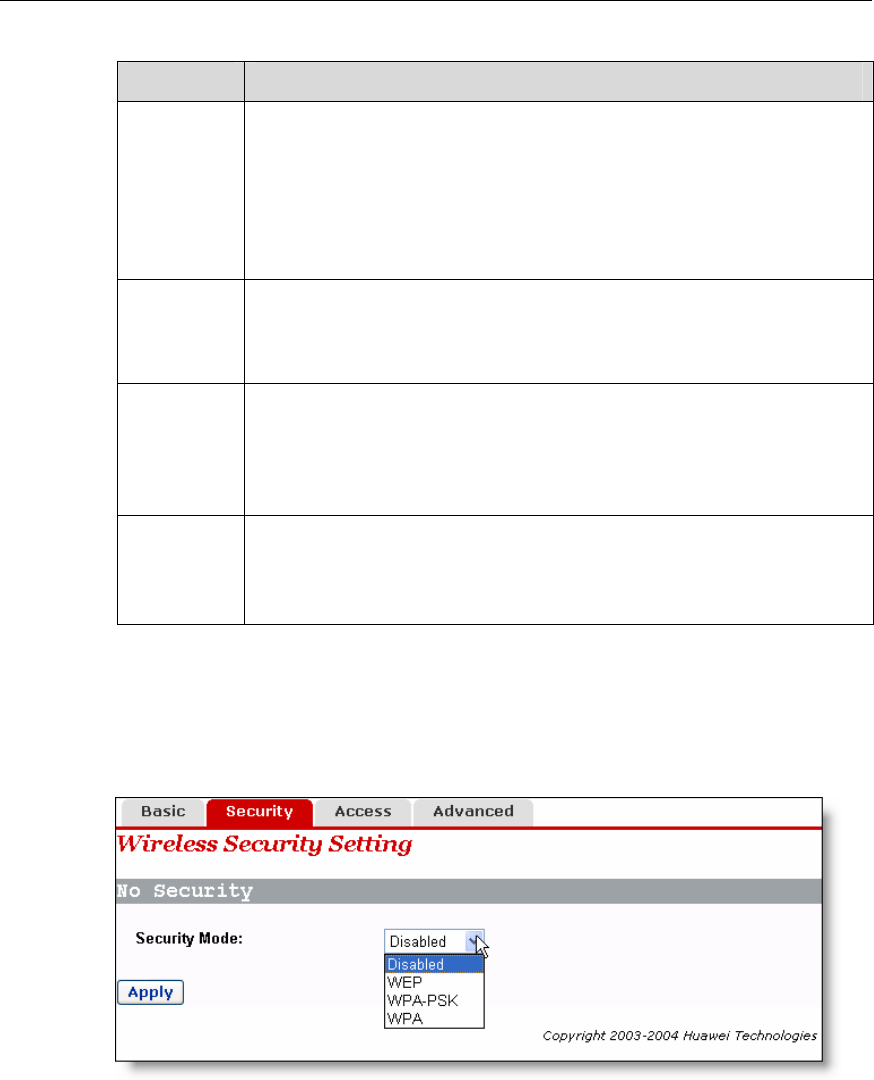
4.5.2 Wireless Security Setting
T u security. his page allows yo to set the wireless data encryption to ensure the
Figure 4-29 Wireless security setting
Three encryption options are available from the [Security Mode] drop-down list: WEP,
WPA-PSK, and WPA. Select any option to display the corresponding configuration
items. To disable the encryption, select the Disabled option. The following introduces
their configurations respectively.
User Manual
Aolynk VDR824 ADSL2+ VoIP Broadband Router/
Aolynk VDR824g ADSL2+ VoIP Wireless Broadband Router 4 Web-based Basic Configuration
38
ss
tted
e
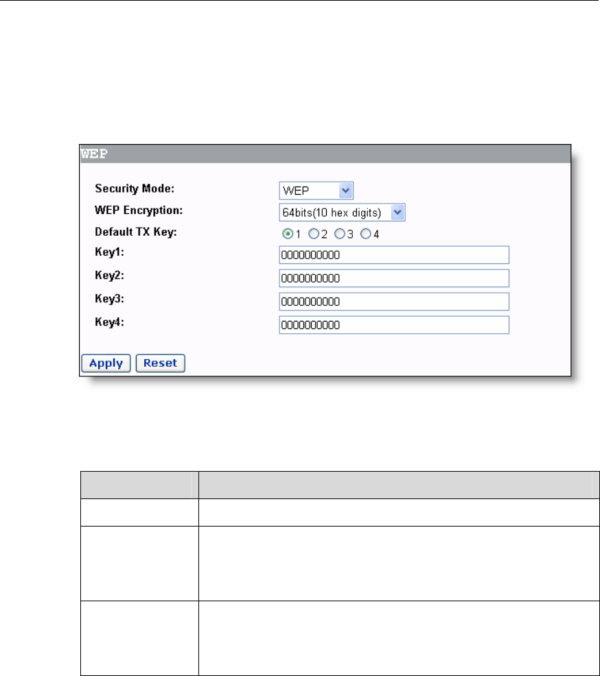
I. WEP
Wired equivalent privacy (WEP) is an encryption mechanism to protect the wirele
data communication. WEP uses the 64-bit or 128-bit key to encrypt data transmi
among all the nodes of the wireless LAN, ensuring data security. To encode/decod
data transmission, all the nodes must use the same key.
Figure 4-30 WEP settings
-8 Description of the WEP items Table 4
Item Description
WEP Encryption Select 64bits or 128bits from the drop-down list.
Default TX Key
Select one from four keys as the encryption key used in the
wireless network. The options from 1 to 4 correspond to Key1 to
Key4 respectively. For example, select 1 to make Key1 as the
encryption key.
Key(1 to 4)
Type in the WEP key in the corresponding text box to join the
existing wireless network. For the 640bit encryption algorithm,
10 hex digits are needed; for the 128-bit encryption algorithm, 26
hex digits are needed.
User Manual
Aolynk VDR824 ADSL2+ VoIP Broadband Router/
Aolynk VDR824g ADSL2+ VoIP Wireless Broadband Router 4 Web-based Basic Configuration
39
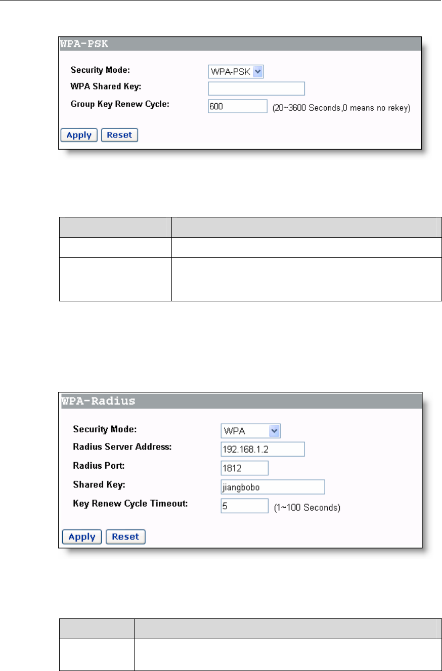
II. WPA-PSK
A-PSK setting items
Figure 4-31 WPA-PSK settings
Table 4-9 Description of the WP
Item Description
WPA Shared Key Type in a standard key ranging from 8 to 32 characters.
Group Key Renew
Cycle
When the set time times out, the VDR824/824g rene
key. The time ranges from 20 seconds to 3600 secon
it is set to 0, the VDR824/824g never renews the key.
ws the
ds. If
III. WPA
WPA is used together with the Radius server. Note that the Radius server a
VDR824/824g must communicate with each other.
nd the
Description of the WPA-Radius setting items
Figure 4-32 WPA-Radius settings
Table 4-10
Item Description
Radius Server
Address Type in the IP address of the Radius server.
User Manual
Aolynk VDR824 ADSL2+ VoIP Broadband Router/
Aolynk VDR824g ADSL2+ VoIP Wireless Broadband Router 4 Web-based Basic Configuration
40
Item Description
Radius Port Type in the port number of the Radius server.
Shared Key Type in the shared key between the VDR824/824g and the server
Key Renew
Cycle Timeout When the set time times out, the VDR824/824g renews the key.
The time ranges from 1 second to 100 seconds.
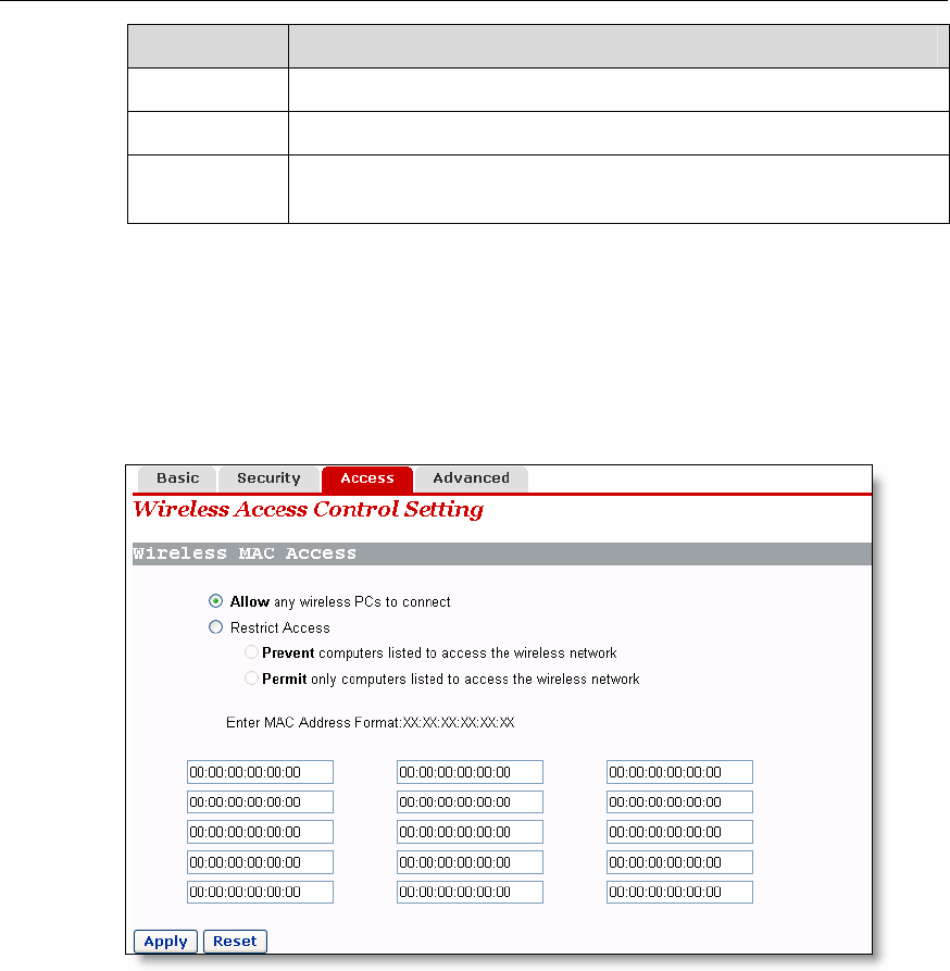
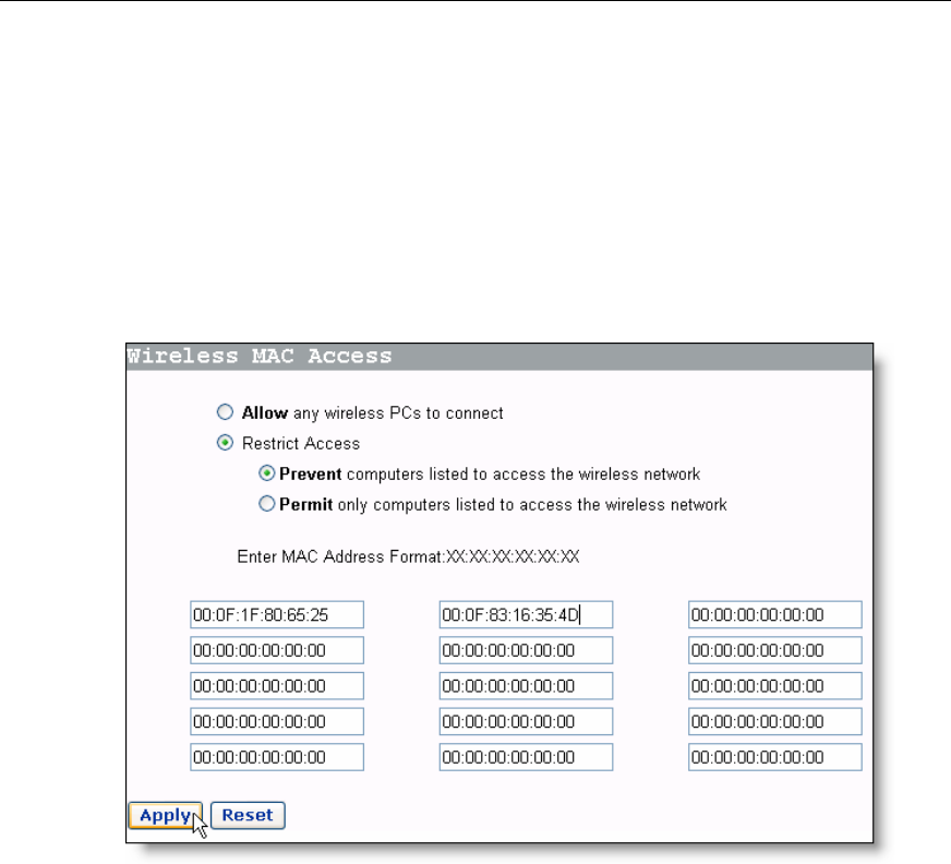
less Access Control 4.5.3 Wire
twork.
work by
Wireless access control can restrict the PC in the LAN to access the wireless ne
This page allows you to block or permit some PCs to access the wireless net
specifying the MAC addresses.
Figure 4-33 Wireless access control setting
To restrict the PC that accesses the wireless network, three options are available:
I. Allow all the PCs to access the wireless network
Keep the default setting unchanged. Select the Allow any wireless PCs to connect
option, as shown in Figure 4-33.
II. Block only the PCs listed in the MAC address list to access the wireless
network
Select the Restrict Access option first, then the Prevent computers listed to access the
wireless network option, and finally type in the MAC addresses of the PCs to be
blocked in the corresponding text box (the format is ××:××:××:××:××:××).
User Manual
Aolynk VDR824 ADSL2+ VoIP Broadband Router/
Aolynk VDR824g ADSL2+ VoIP Wireless Broadband Router 4 Web-based Basic Configuration
41
in the MAC address list to access the wireless
network
ss
s
s
III. Permit only the PCs listed
Select the Restrict Access option first, then the Permit only computers listed to acce
the wireless network option, and finally type in the MAC addresses of the PCs to be
permitted in the corresponding text box. In this case, only the PCs whose addresse
match those listed in the MAC address list can access the wireless network.
Example: Perform the following settings to block only the PCs whose MAC addresse
are 00-0F-1F-80-65-25 and 00-0F-83-16-35-4D to access the wireless network.
f wireless access control setting Figure 4-34 Example o
User Manual
Aolynk VDR824 ADSL2+ VoIP Broadband Router/
Aolynk VDR824g ADSL2+ VoIP Wireless Broadband Router 4 Web-based Basic Configuration
42
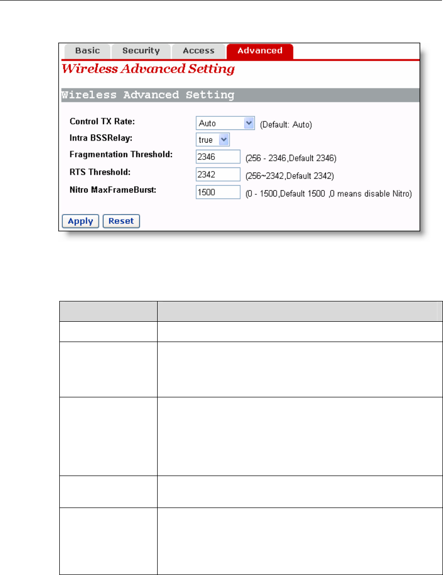
Advanced Setting 4.5.4 Wireless
Figure 4-35 Wireless advanced setting
Table 4-11 Description of the wireless advanced setting items
Item Description
Control TX Rate Select the default Auto option or other options.
Intra BSSRelay
Select the true option to permit the communi
wireless clients related to the AP of the VDR824/8
the false option to block the communication
wireless clients.
cation among the
24g; select
among these
Fragmentation
Threshold
If the data frame to be transmitted excee
fragmentation threshold, the data frame is fragm
wireless network with great interference or hi
smaller fragmentation threshold can add the tran
reliability, while larger fragmentation threshold
ds the set
ented. For a
gh utilization,
smission
can improve
cy. the efficien
RTS Threshold Request To Send threshold used to set the size of RTS
packets.
Nitro
MaxFrameBurst
larger value can improve the transmission efficiency, but
require high-quality network connection. Also
needs to support the Nitro technology. When the value is set
Number of packets during the uninterrupted transmission. The
, the client
to 0, this function is disabled.
User Manual
Aolynk VDR824 ADSL2+ VoIP Broadband Router/
Aolynk VDR824g ADSL2+ VoIP Wireless Broadband Router 4 Web-based Basic Configuration
43
4.6 Device
e five tabs are
ab to enter
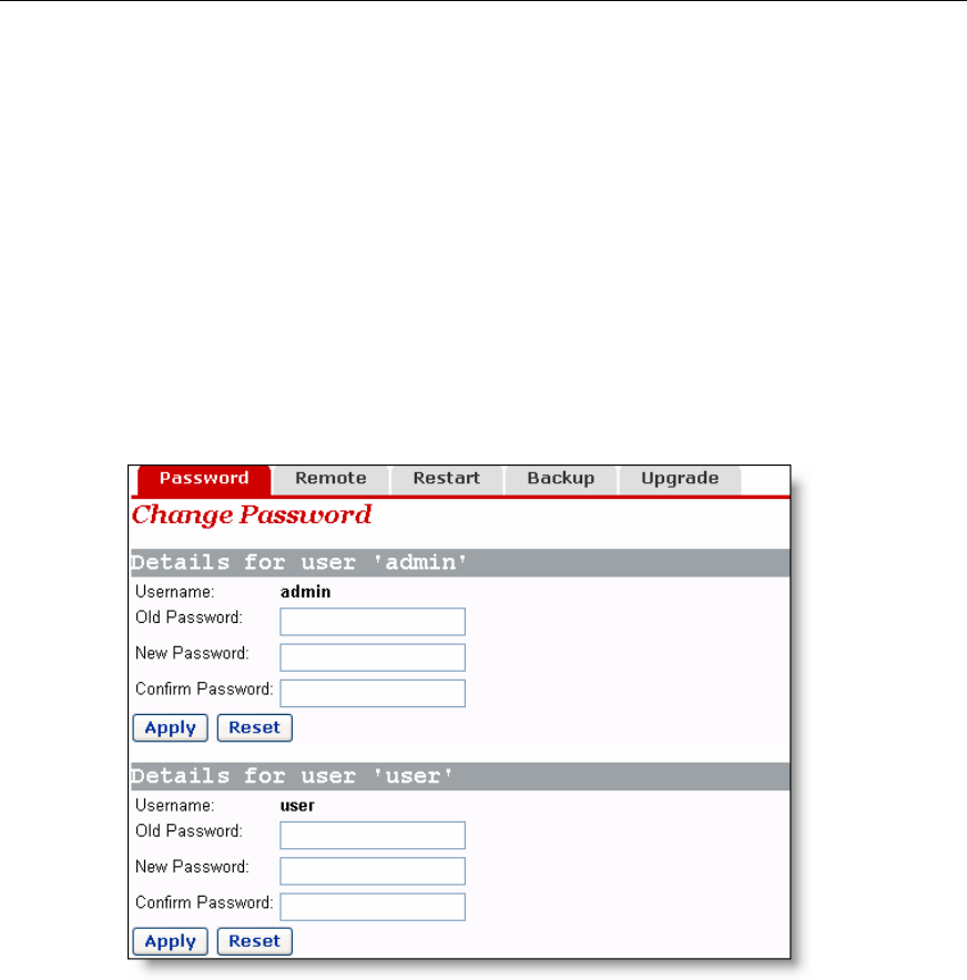
4.6.1 Passw
/824g via two user
s while the common
n enter
the following [Password] page to change the login passwords for two users. The
Click [Device] in the navigation bar to enter the corresponding page wher
available: Password, Remote, Restart, Backup and Upgrade. Click any t
your desired configuration page.
ord
You can access log into the Web configuration page of VDR824
name: admin and user. The administrator has the maximum right
user can only access part of the configuration pages. Only the administrator ca
common user can only change its own password.
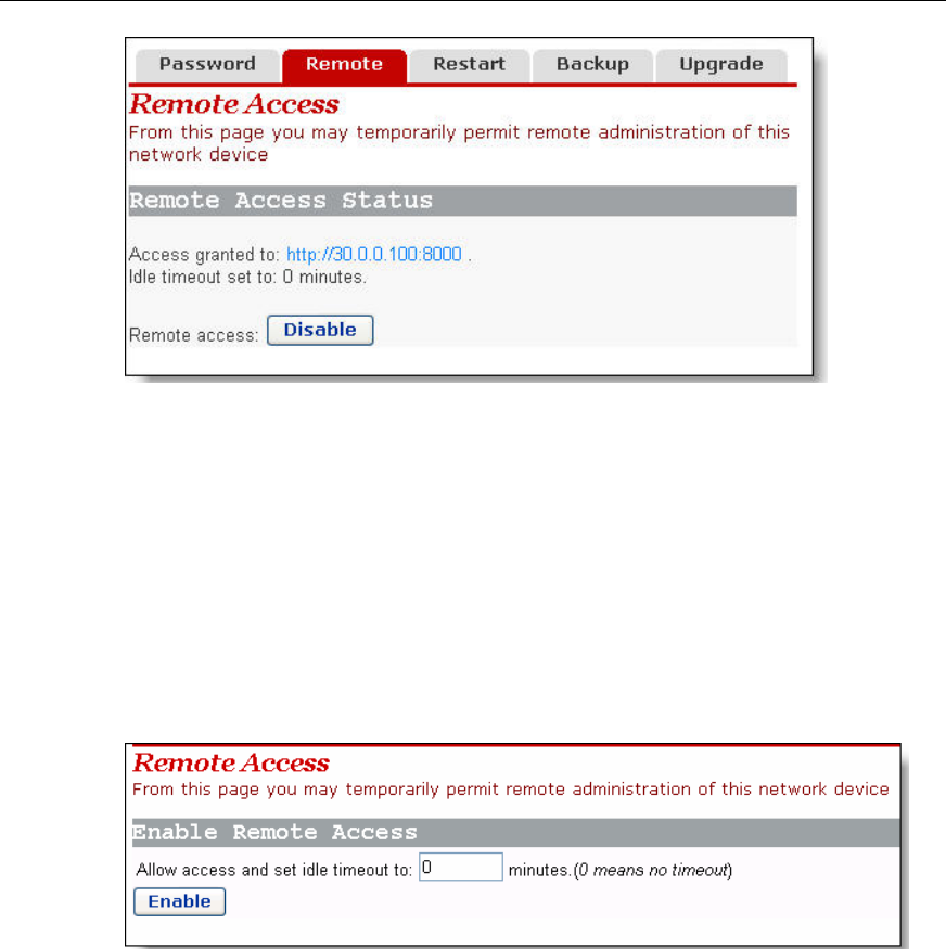
4.6.2 Remote Access
If remote access is enabled, you can view the current configuration page and manage
the VDR824/824g remotely.
By default, the remote access is enabled and the idle timeout time is set to 0 (see
Figure 4-37). In this case, remote access is kept alive.
Figure 4-36 Change the password
By default, admin and user are the passwords for administrator and common user
respectively.
To change the password, type in the related information in the [Old Password], [New
Password] and [Confirm Password] text boxes, and then click <Apply>.
User Manual
Aolynk VDR824 ADSL2+ VoIP Broadband Router/
Aolynk VDR824g ADSL2+ VoIP Wireless Broadband Router 4 Web-based Basic Configuration
44
Figure 4-37 Remote access page – remote access enabled
ates the port for remote management is 8000, so you can manage the
ser.
n
Figure 4-37 indic
VDR824/824g remotely by entering http://xxx.xxx.xxx.xxx:8000 in your Web brow
The xxx.xxx.xxx.xxx is the IP address of the WAN port on the VDR824/824g. If multiple
WAN services are configured and all of them obtain the IP addresses, the IP address of
any service can be used for remote access.
To disable the remote access, click <Disable> on the [Remote Access] page to ope
the page as below.
this case, you can set the idle timeout time to a desired value other than 0 in the text
page. Thus, when you click <Enable> to enable the remote access next time,
the VDR82 psed idle time and terminates the remote connection to
avoi acks when the elapsed idle time exceeds the set idle time.
Figure 4-38 Remote access page – remote access disabled
In
box on the
4/824g tracks the ela
d remote att
User Manual
Aolynk VDR824 ADSL2+ VoIP Broadband Router/
Aolynk VDR824g ADSL2+ VoIP Wireless Broadband Router 4 Web-based Basic Configuration
45
Caution:
A remote connection is maintained only when the idle timeout time is set to 0. If you set
the timeout time to another value, remote access is disabled automatically whe
the VDR824/824g restarts.
Because remote access is enabled by default, you need to configure the passwo
prevent network invasion by the Internet users.
never
rd to
Restoring Factory Default Settings
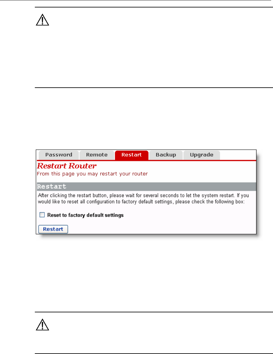
This page allows you to restart the VDR824/824g, or reset all configurations
default settings.
4.6.3 Restarting/
to factory
elect the [Reset to factory
Figure 4-39 Restart Router page
To restart the VDR824/824g, click <Restart>.
To reset all configurations to the factory default settings, s
default settings] check box and click <Restart>.
Caution:
It may take several seconds to restart the VDR824/824g.
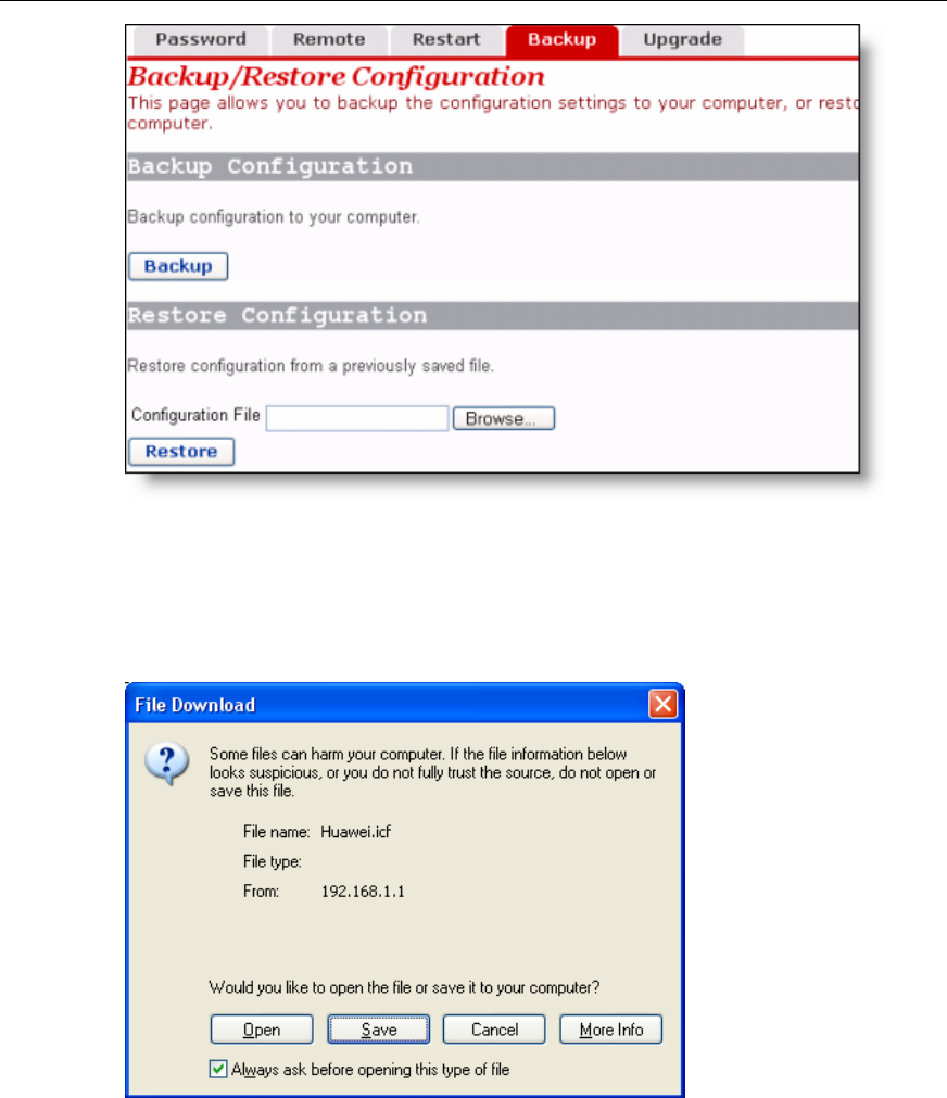
4.6.4 Backing Up/Restoring Configuration
This page allows you to back up the current configuration to your PC, or restore the
configuration from a previously saved file.
User Manual
Aolynk VDR824 ADSL2+ VoIP Broadband Router/
Aolynk VDR824g ADSL2+ VoIP Wireless Broadband Router 4 Web-based Basic Configuration
46
ration page
I.
Figure 4-40 Backup/Restore Configu
Back up the current configuration
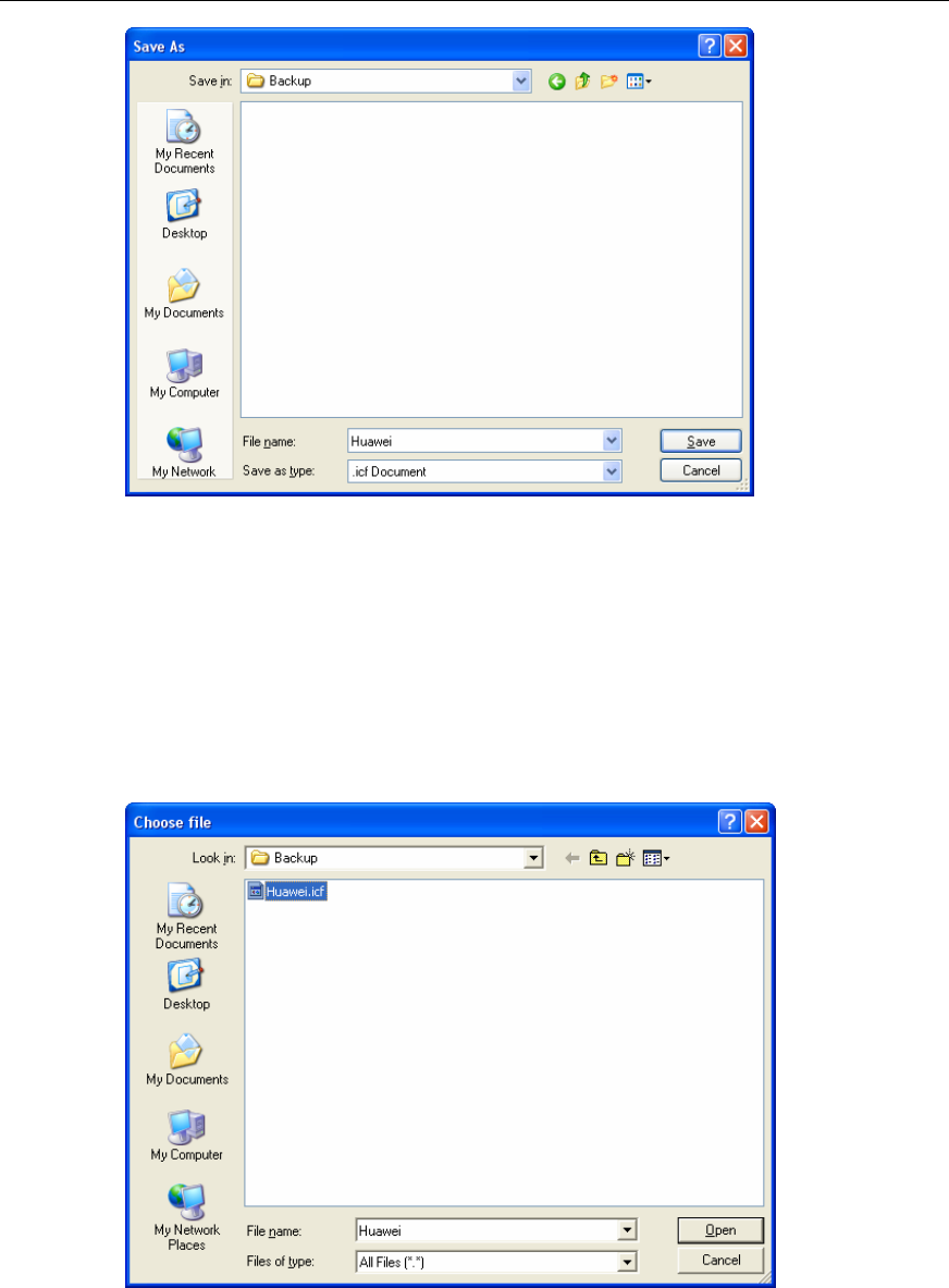
Click <Backup> to open the [File Download] dialog box as below.
Figure 4-41 File Download dialog box
Click <Save> to open the [Save As] window as below.
User Manual
Aolynk VDR824 ADSL2+ VoIP Broadband Router/
Aolynk VDR824g ADSL2+ VoIP Wireless Broadband Router 4 Web-based Basic Configuration
47
Figure 4-42 Save the configuration file
Select a directory to save the file and type in a valid file name (with the .icf suffix), and
ck <Save> to back up the current configuration to the file. then cli
II. Use the file to restore the configuration
To use the previously saved file to restore the configuration, click <Browse…> in Figure
4-40 to open the [Choose file] window as below.
Figure 4-43 Choose the backup file
Find the configuration file and then click <Open> to open the page as below. Click
<Restore> to use the file to restore the configuration.
User Manual
Aolynk VDR824 ADSL2+ VoIP Broadband Router/
Aolynk VDR824g ADSL2+ VoIP Wireless Broadband Router 4 Web-based Basic Configuration
48
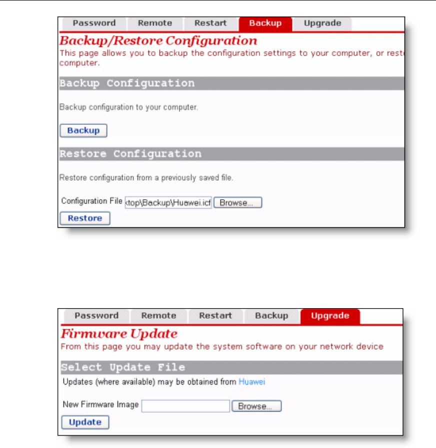
4.6.5 Upgrade
Figure 4-44 Restore the configuration
Figure 4-45 Software upgrade
date file downloaded from Huawei technical support website, or
click <Browse…> to select this file on your PC and then click <Update>.
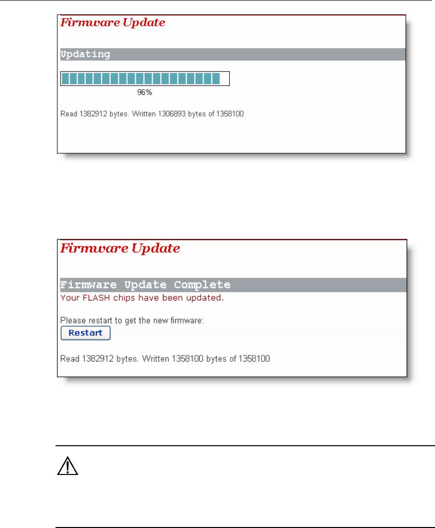
uring the update, a progress bar appears on the page as below.
This page allows you to upgrade the software of the VDR824/824g.Type in the local
path of the software up
D
User Manual
Aolynk VDR824 ADSL2+ VoIP Broadband Router/
Aolynk VDR824g ADSL2+ VoIP Wireless Broadband Router 4 Web-based Basic Configuration
49
Figure 4-46 Update progress
Figure 4-47 shows that the update is complete. Now, you need to restar
VDR824/824g by clicking <Restart>.
t the
Figure 4-47 Complete the update
Caution:
Aft the upgrade and restart, you ner eed to restore factory default settings to ensure the
mnor al configuration.
Click <Huawei> to access Huawei technical support website to obtain the latest
twsof are version.
User Manual
Aolynk VDR824 ADSL2+ VoIP Broadband Router/
Aolynk VDR824g ADSL2+ VoIP Wireless Broadband Router 4 Web-based Basic Configuration
50
4.7 St
bs
red
4.7.1 Status
atus
Click [Status] in the navigation bar to enter the corresponding page where three ta
are available: Status, Log, and Search Service. Click any tab to enter your desi
configuration page.
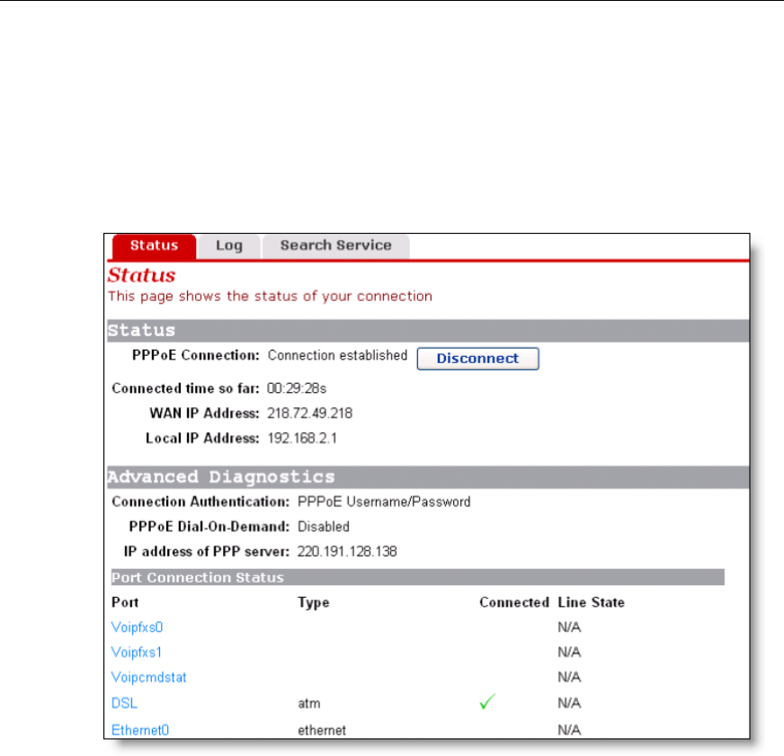
Figure 4-48 Status configuration page
This page displays useful information about the configuration of the VDR824/824g,
n)
z Routing table
z Connection status of current DSL, Ethernet and USB port
z WAN port status
z LAN port status
z Statistics on all interfaces
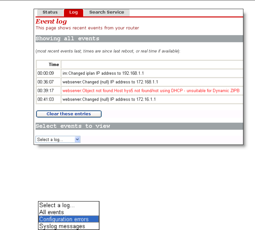
4.7.2 Log
This page records all types of events occurring during the running of the DR811/814.
including:
z Details of network connection
z Some important system information (hardware and version informatio
User Manual
Aolynk VDR824 ADSL2+ VoIP Broadband Router/
Aolynk VDR824g ADSL2+ VoIP Wireless Broadband Router 4 Web-based Basic Configuration
51
corresponding event information.
Figure 4-49 Log
The drop-down list in the [Select events to view] section includes the options as shown
in the figure below. Select an event type to view the
Click <Clear these entries> to clear the currently displa
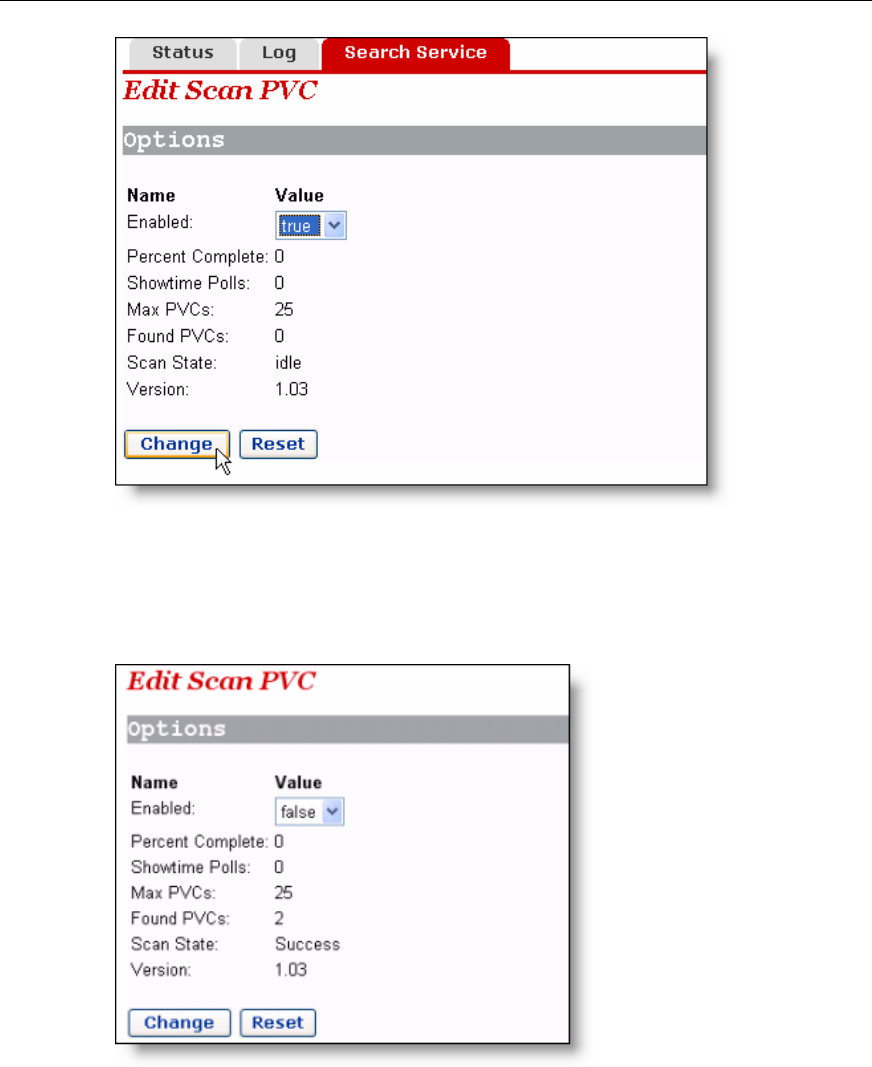
The [Edit Scan PVC] page allows you to search the
your ISP has configured PVC services within the se
these PVC services will be automatically configured to
Connections] page until the number of services reache
yed events.
4.7.3 PVC Search
currently unused PVC settings. If
archable range, after the search,
the service list on the [WAN
list. s eight in this
User Manual
Aolynk VDR824 ADSL2+ VoIP Broadband Router/
Aolynk VDR824g ADSL2+ VoIP Wireless Broadband Router 4 Web-based Basic Configuration
52
Figure 4-50 PVC Scan page
Select the true option from the drop-down list in Figure 4-50, and then click <Change>
to start the search. It may take about five minutes.
Figure 4-51 Search PVC
,
to
AN service list as below.
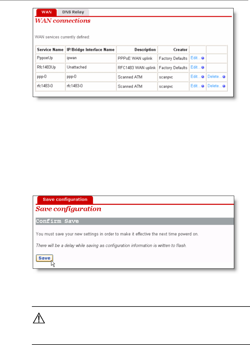
As shown in Figure 4-51, two PVCs are found. Click [WAN Setup] in the navigation bar
you will find that two services found by the VDR824/824g are automatically added
the W
User Manual
Aolynk VDR824 ADSL2+ VoIP Broadband Router/
Aolynk VDR824g ADSL2+ VoIP Wireless Broadband Router 4 Web-based Basic Configuration
53
Figure 4-52 Add the found services automatically
d, you need to edit these automatically added
4.8 Sav
ation] page after all the configurations are complete. Click
If the PPPoE or PPPoA service is foun
services by typing in a user name and a password.
e the Configuration
Enter the [Save configur
<Save> to save your configurations so that they take effect when the VDR824/824g
restarts.
Figure 4-53 Save the configuration
Caution:
Do save your settings, otherwise, they will be lost after the VDR824/824g restarts.