Huawei Technologies HG8247HB EchoLife Gateway PON Terminal User Manual
Huawei Technologies Co.,Ltd EchoLife Gateway PON Terminal
UserManual.wiki
>
Huawei Technologies
>
HG8247HB User Manual
User Manual
Navigation menu
Upload a User Manual
Namespaces
Wiki Guide
HTML
PDF
Info
Views
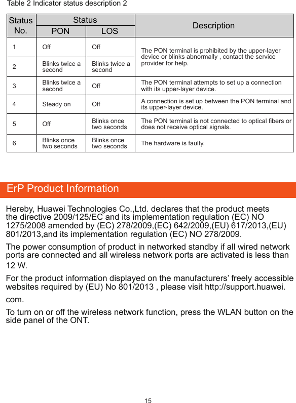
User Manual
Discussion / Help
Navigation