Huawei Technologies HG8247HB EchoLife Gateway PON Terminal User Manual
Huawei Technologies Co.,Ltd EchoLife Gateway PON Terminal
User Manual

Quick Start
EchoLife Gateway PON Terminal
FCC ID:QISHG8247HAFCC ID:QISHG8247HB

Safety Precautions
To use the device properly and safely, read the safety precautions carefully before using the device
and strictly observe these precautions when using the device.
Do not look directly into the optical port without eye protection.
Keep the device out of the reach of children as the components or accessories may be
swallowed.
The power supply voltage of the device must meet the requirements on the input voltage of the
device.
Do not use any power adapters that are not in the standard conguration. Otherwise, the
device may be abnormal or unsafe.
If the power adapter is damaged and its internal circuit is exposed due to man-made factors,
do not touch the exposed circuit, which may bring safety risks.
Prevent objects, such as metal, from entering the device through the heat dissipation hole.
Dry your hands before connecting or disconnecting cables. Stop the device and switch off the
power before connecting or disconnecting cables.
Switch off the power and disconnect all cables, including the power cable, optical ber, and
network cable, during periods of lightning activities. The socket-outlet shall be installed near
the power adapter and shall be easily accessible. Before use the power adapter, please check
no damage on the adapter.
Do not lead the strength member of the optical ber or other metal parts indoors. Do not install
telephone lines, network cables, power adapters or power adapter cables outdoors. Adopting
these measures will help prevent device damage and bodily injuries which are especially prone
during thunderstorms.
Install the device according to the requirements of the manufacturer. To be specic, reserve
at least 10 cm for heat dissipation at the top and four sides of the device, keep the device
away from ammable objects, highly magnetic or electric devices, such as microwave ovens,
refrigerators, and mobile phones.
Do not place any object on the device, so that the device will not be damaged due to
overheating or deformation.
If an abnormality occurs, for example, liquid entering the device, smoke, unusual sound,
and smell, stop the device immediately, switch off the power, disconnect all cables (such as
the power cable, optical cable, and network cable) to the device, and contact the authorized
service center.
Do not disassemble the device without permission. In the case of a device fault, contact the
authorized service center.
Dispose of the packing materials, expired batteries, and old or abandoned devices in
accordance to local laws and regulations (recycling them is strongly recommended).
Do not change the structure, safety design, or performance design of the device without prior
authorization.
Safety precautions:
Fireproof precautions:
Keep the device away from large heat source equipment, bare ames, and high-power devices,
such as electric heaters, candles, and blow drier, to eliminate safety risks.
If there are aged cables or power socket facilities on the power supply line to or near the
device, replace them in time to eliminate safety risks. The power supply voltage of the device
must meet the input voltage requirement.
Product Overview
Product Function
HG8247 series
4 Ethernet ports
2 POTS ports
1 USB port
1 CATV port
Wi-Fi access
NOTE
- The devices that support Wi-Fi access are classied into devices equipped with
external antennas and devices equipped with internal antennas.
- If some device types are not in the preceding list, refer to http://www.huawei.com.
Power adapter input: 100–240 V AC, 50–60 Hz
System power supply: See the nameplate on the device.
Ambient temperature: 0ºC to +40ºC
Ambient humidity: 5%–95% (non-condensing)
For other technical specications, see the following table.
Technical Specifications
GPON Terminal Weight
(Including the Power Adapter)
Maximum System
Power Consumption
HG8247 series About 500 g ≤18 W
NOTE
The appearance shown in this document may be different from the actual appearance of the product.
The actual product provided by the carrier prevails.
Installing the GPON&XG-PON Terminal
1. Do not install PON terminals outdoors or on the outdoor cabinets.
2. PON terminals can be mounted onto a wall or be placed on a workbench.
Do not install PON terminals in other modes, such as the ceiling.
3.The terminal cannot be connected to other devices such as GPON
terminals, switch and router.
4. After the PON terminal is installed with a foot-stand, do not remove the
foot-stand unless it is necessary. When you remove the foot-stand, apply
force evenly on the two sides of the foot-stand to avoid damages to the
PON terminal.
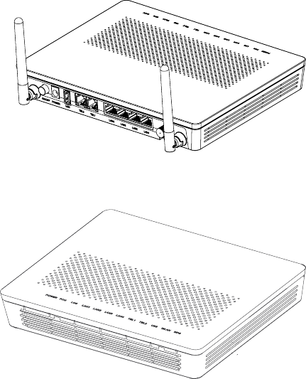
Mounting a GPON terminal on the desk
At present, only HG8247H ONTs are equipped with external
antennas. The figure below shows an HG8247H that is horizontally placed
on a desk.
The figure blow uses an HG8247H ONT as an example to show the ONT
that is horizontally placed on a desk.
Mounting terminal vertically on the desk
(Only supported by some product models)
The following figure uses an HG8247H ONT as an example to show the
ONT that is vertically placed on a desk.
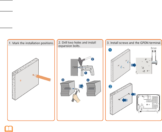
Mounting a GPON Terminal Onto The Wall
(Only supported by some product models)
Step 1 Mark the positions of two holes used for mounting a GPON terminal, ensure that
the two holes have the same spacing as the two mounting holes.
Step 2 Select a proper drill according to the outer diameter of the screws. Use a
hammer drill to drill the marked positions on the wall. Then clean the wall and
install two expansion bolts.
Step 3 Use a screwdriver to fasten the screws into the expansion bolts, leaving the heads
of the screws 3 mm over the wall. Then install the GPON terminal to the screws.
6
NOTE
This terminal is mainly placed horizontally on a desk. When it is mounted
onto a wall, the silkscreen of its indicator is reversed. If you have a special
requirement on the silkscreen, purchase another terminal.
7
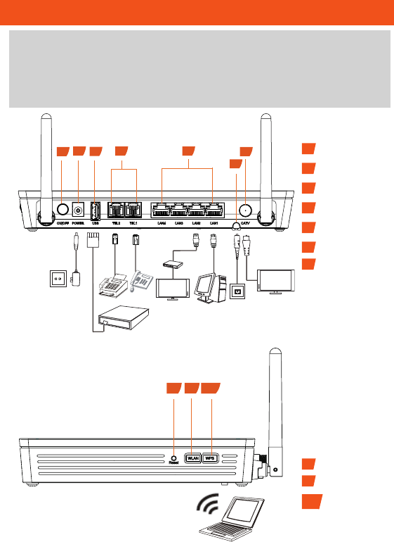
Connecting Cables
This document uses the HG8247H as an example to describe the
connections. Ports on GPON terminals of other types may be different.
Therefore, connect cables based on the ports that are actually supported
by the device. If the external device is different from the device in the figure,
refer to the description for connections of the external device.
1Power switch
2Power port
3USB port
4POTS port
5Ethernet port
6Optical port
7CATV port
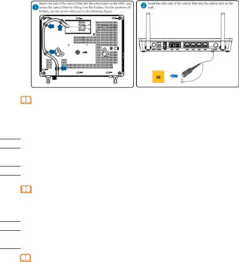
8Reset
9WLAN switch
10 WPS switch
125
4
6
7
3
Fax machine
Phone
PC
TV set
IP STB
Optical port
Power socket
USB storage device
TV set
Wi-Fi terminal
89
10

10
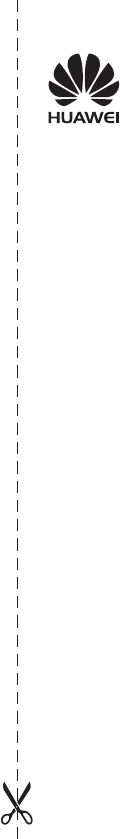
Step 1 Use an optical ber to connect the optical port to the ONT and the optical port on
the wall.
• The optical ports of the XG-PON terminals are at the back of the device. For how
to connect the optical ports, see the following gure (The HN8247H is used as an
example here.):
NOTE
1.The optical ber connectors of the HN8xxx series are SC/UPC .
2.To ensure normal use of bers, make sure that the ber bend radius is larger than 30 mm.
11
Before enabling the WPS encryption function of a PON terminal, ensure that the function is
set in the system software in advance. After successful setting, press the WPS switch for the
settings to take effect.
NOTE
Step 6 Use a USB data cable to connect the USB port to the USB storage device.
Step 7 Press the WLAN switch to enable the Wi-Fi access function. By default, this
function is enabled.
Step 8 Press the WPS switch to enable the WPS encryption function.
NOTE
1.The optical ber connector connected to the optical port on the wall varies depending on
actual conditions.
2.To ensure normal use of bers, make sure that the ber bend radius is larger than 30 mm.
Step 2 Use a coaxial cable to connect the CATV port to a TV set or set top box (STB).
Step 3 Use a network cable to connect the LAN/10G LAN port to a PC or the
Ethernet port on the IP STB.
Step 4 Use a phone line to connect the TEL port to a phone or fax machine.
Step 5 Use a power adapter to connect the POWER port to the power socket.
The preceding gure connects the power adapter as an example. When connecting the
backup battery unit , please see the usage guide to the backup battery for details .
NOTE
• The optical ports of the HG8047 series,
. For how to connect the optical ports, see the following gure
are at the back of the device

Configuring Wi-Fi Parameters
Step 1 Choose the WLAN tab and choose WLAN Basic Configuration.
NOTE
HN8247H is different from GPON terminal, Choose the Advanced Confi
guration>WLAN tab and choose 2.4G Basic Network Settings. (If
you want to configure 5G Wi-Fi, choose 5G Basic Network Settings.)
Step 2 In the pane, select the Enable WLAN option box. In the dialog box that is
displayed, set the basic Wi-Fi parameters, including the SSID, authentication
mode, and encryption mode. For example,
-SSID Name: WirelessNet (the name of a wireless network searched by the
Wi-Fi terminal)
-Authentication Mode: WPA Pre-Shared Key
-Encryption Mode: TKIP
-WPA PreSharedKey: Password (the authentication password for the Wi-Fi
terminal to access a wireless network)
Step 3 Click Apply.
12
Logging in to the Web Configuration Window
Step 1 Set the IP address of the PC in the same subnet as the management IP address
of the GPON terminal.
Step 2 Enter the management IP address of the PON terminal in the address bar of
Internet Explorer and press Enter.
The login window is displayed.
Step 3 In the login window, select your preferred language, enter the user name and
password ( printed on the nameplate of the device.), and click Login. After the
password is authenticated, the Web configuration window is displayed.
NOTE
-Shipped from different manufacture batches, the nameplates of some devices do not have
the IP address, user name, and password printed. In such a case, log in to the device using
192.168.100.1 (or 192.168.1.1), root (user name), and admin (password).
-If you do not perform any operations after logging in to the system for ve minutes, you will
exit the system and the system automatically returns to the login interface.
-The system will be locked if you input incorrect user name and password three consecutive
times. One minute later, it will be unlocked.
-Change the initial password after logging in to the web page.
NOTE
You can nd the default management IP address on the nameplate of the
device.

13
ONT supporting Wi-Fi (such as HG8247H), a wireless network coverage is subject to
the number, thickness, and positions of walls, materials, ceilings, or other objects that
radio signals traverse. Besides, metarial type and background radio frenquency (RF)
noise also affect the coverage of a wireless network. You can maximize the coverage
of a wireless network using the following methods:
1. Decrease the number of walls and ceilings between HG8247H and other
network devices.
Each wall or ceiling reduces the coverage of a wireless network by one to 30
meters. Install HG8247H at a proper place to avoid walls or ceilings whenever
possible.
2. Observe the straight line rule when installing network devices.
The distance for which signals have to traverse at a 45° corner of two 0.5 meter-
thick walls reaches approximately one meter. To better receive signals, devices
should be installed at places where signals can directly traverse walls or ceilings.
3. Note the impact of building materials on the wireless network coverage.
A metal door or aluminum wall may limit the coverage of a wireless network.
Install access points, wireless routers, and computers, so signals can traverse
walls or open passageways. Materials and objects such as FRP products, metal
products, insulative walls, filing cabinets, bricks, and concrete weaken radio
signals.
4. When connecting ONT (such as HG8247H) to a wireless network, keep it far
from the following devices:
- Electronic devices or components that produce RF noises (keep a distance of
more than 2 meters between such a device and HG8247H.)
- 2.4 GHz wireless mobile phones or X-10 devices (such as microwave ovens,
home security systems, blue-tooth devices, and refrigerators) that greatly weaken
or even eliminate radio signals. Even if a 2.4 GHz wireless mobile phone is not
connected to a wireless network, the phone base still sends signals that interfere
the wireless network.
NOTE

14
Indicator Description
Table 1 Indicator status description 1
Indicator Status Description
CATV
Always on The CATV function is enabled and CATV signals are
received.
Off The CATV function is disabled or CATV signals are not
received.
WPS
Steady on The WPS function is enabled.
Blinking A Wi-Fi terminal is accessing the system.
Off The WPS function is disabled.
WLAN
Steady on The WLAN function is enabled.
Blinking Data is being transmitted on the WLAN port.
Off The WLAN function is disabled.
USB
Steady on The USB port is connected and is working in the host
mode, but no data is transmitted.
Blinks twice a
second Data is being transmitted on the USB port.
Off The system is not powered on or the USB port is not
connected.
TEL1–
TEL2
Steady on The terminal is registered with the softswitch but no
service ows are transmitted.
Blinking Service ows are transmitted.
Off The terminal is not powered on or fails to be registered
to the softswitch.
LAN1–
LAN4/
10G LAN
Steady on The Ethernet connection is in the normal state.
Blinking Data is being transmitted on the Ethernet port.
Off The Ethernet connection is not set up.
LOS/PON See Table 2.
POWER
Steady green The terminal is powered on.
Off The power supply is cut off.

ErP Product Information
Hereby, Huawei Technologies Co.,Ltd. declares that the product meets
the directive 2009/125/EC and its implementation regulation (EC) NO
1275/2008 amended by (EC) 278/2009,(EC) 642/2009,(EU) 617/2013,(EU)
801/2013,and its implementation regulation (EC) NO 278/2009.
The power consumption of product in networked standby if all wired network
ports are connected and all wireless network ports are activated is less than
12 W.
For the product information displayed on the manufacturers’ freely accessible
websites required by (EU) No 801/2013 , please visit http://support.huawei.
com.
To turn on or off the wireless network function, press the WLAN button on the
side panel of the ONT.
15
Status
No.
Status Description
PON LOS
1Off Off The PON terminal is prohibited by the upper-layer
device or blinks abnormally , contact the service
provider for help.
2Blinks twice a
second
Blinks twice a
second
3Blinks twice a
second Off The PON terminal attempts to set up a connection
with its upper-layer device.
4 Steady on Off A connection is set up between the PON terminal and
its upper-layer device.
5Off Blinks once
two seconds
The PON terminal is not connected to optical bers or
does not receive optical signals.
6Blinks once
two seconds
Blinks once
two seconds The hardware is faulty.
Table 2 Indicator status description 2

16
The LOS indicator blinks.
If the LOS indicator blinks once two seconds, check whether the pigtail fiber is properly
connected and the connector is clean.
If the GPON terminal blinks twice a second, contact the service provider for help.
The PON indicator is off.
Check whether the OPTICAL port and optical fiber is properly connected.
The GPON terminal fails to register with the upper-layer device. Contact the service
provider for help.
The phone does not ring upon an incoming call but communication is in normal state when the
phone is in off-hook state.
The GPON terminal provides a maximum of 60 V AC ringing current voltage. Check
whether the ringing current voltage of the phone is higher than 60 V AC. If it is higher
than 60 V AC, replace it with another phone.
How to reset the GPON terminal?
Press Reset by using a needle-type object.
How can I restore factory defaults?
Press Reset by using a needle-type object for longer than 10s to restore factory
defaults and reset the GPON terminal. If the indicator is off and then is lit, the system
restarts successfully.
FAQs
User Information
Personal or
company's full name:__________________________________________________
Address/Postal Code:_________________________________________________
Telephone:__________________________________________________________
Email:______________________________________________________________
Product Type:________________________________________________________
Product Serial Number:________________________________________________
Purchase Date:______________________________________________________
Invoice Number:______________________________________________________
Dealer's Name:______________________________________________________
Dealer's Address:_____________________________________________________
Dealer's Telephone:___________________________________________________
Warranty Card
Thank you for choosing Huawei Technologies Co., Ltd. To get better services,
please read this warranty card carefully, ll in the required information, and
preserve this card in good condition.
Preserve well. No reissue.
Dealer's Seal
Limited Warranty
Subject to the exclusions contained below, Huawei Technologies Co., Ltd. (Huawei
for short) warrants its access terminals ("Products") to be free from defects in
materials and workmanship under normal consumer usage for one year from
the date of purchase of the product ("Warranty period"). During the warranty
period, a Huawei authorized service partner shall remedy defects in materials and
workmanship free of charge.
Special Notice:
1. The warranty card shall be applicable only after being stamped by the dealer.
2. The warranty card must be preserved in good condition and free of any scratch or
alteration.
3. To claim such service for defects that are not included in the following exclusion
terms, the warranty card and the invoice that records that product serial number
shall be presented to a Huawei authorized service partner.
Exclusions:
In any of the following cases, the warranty card becomes unenforceable or
inapplicable without prior notice:
1. The defects are caused by improper handling in transportation and assembly.
2. The defects are caused by the fact that the product is dismantled or altered by
anyone that is not from a Huawei authorized service partner.
3. The defects are caused by the fact that the product is used in a harsh environment
that is not suitable for the operation of the product.
4. The defects are caused by any force majeure including but not limited to re,
earthquake, lightning, and tsunami.
5. The defects are caused by the fact that the product is used or handled incorrectly,
roughly or not as instructed in the applicable User Guide.
6. The normal wear and tear, including but not limited to the normal wear and tear of
the shell and the power module, shall not be covered by the limited warranty.
7. The warranty card is altered or illegible, or the product serial number recorded on
the warranty card is inconsistent with the actual one imprinted or labeled on the
product.
In any case that is not covered by this limited warranty or should the warranty expire,
Huawei shall charge for the service(s) claimed for the products if the product is still
remediable. Huawei reserves all rights to interpret this limited warranty.
Huawei Technologies Co., Ltd.
Address: Huawei Industrial Base
Bantian, Longgang
Shenzhen 518129
People's Republic of China
Website: http://www.huawei.com

Issue: 10 (2015-11-30)
BOM number: 31505718
Copyright © Huawei Technologies Co., Ltd. 2015 All rights reserved.
No part of this document may be reproduced or transmitted in any form or by any
means without prior written consent of Huawei Technologies Co., Ltd.
Trademarks and Permissions
and other Huawei trademarks are trademarks of Huawei Technologies Co., Ltd.
All other trademarks and trade names mentioned in this document are the property of
their respective holders.
Notice
The information in this document is subject to change without notice. Unless
otherwise stated, this guide serves only as a guide. All statements, information, and
recommendations in this document do not constitute a warranty of any kind, expressed
or implied.