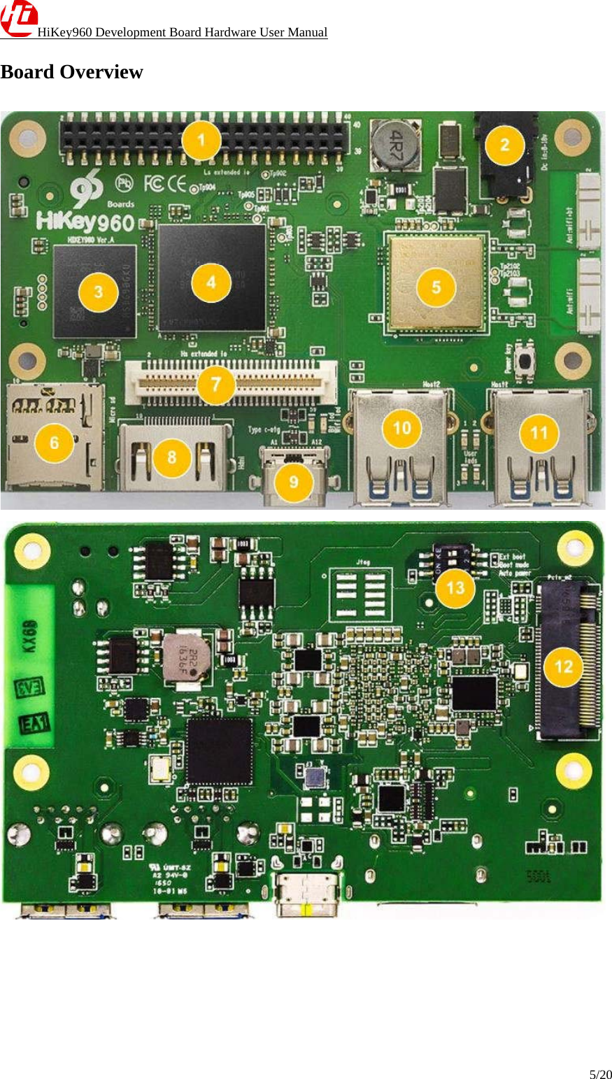
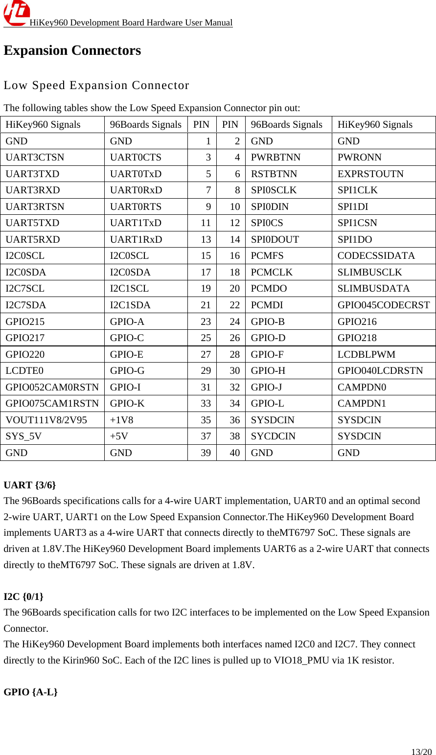
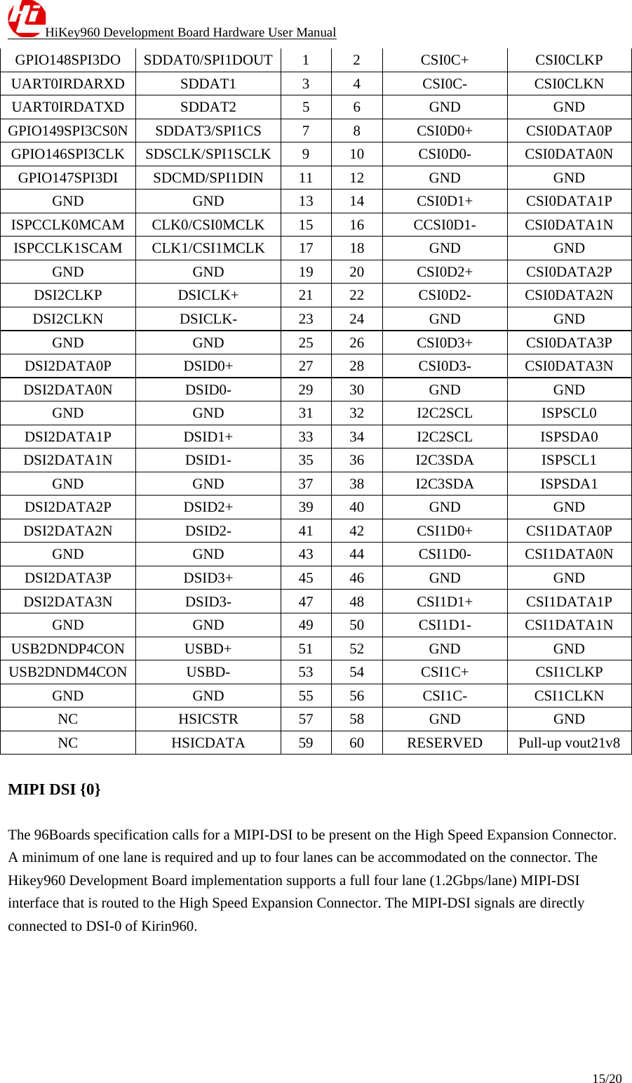
Huawei Technologies HIKEY960 Hikey960 User Manual QISHIKEY960 User Manualx
Huawei Technologies Co.,Ltd Hikey960 QISHIKEY960 User Manualx
UserManual.wiki
>
Huawei Technologies
>
HIKEY960 User Manual
>
User_Manual
Contents
1.
User_Manual
2.
user_manual
3.
Uaser_Manual
User_Manual
Navigation menu
Upload a User Manual
Namespaces
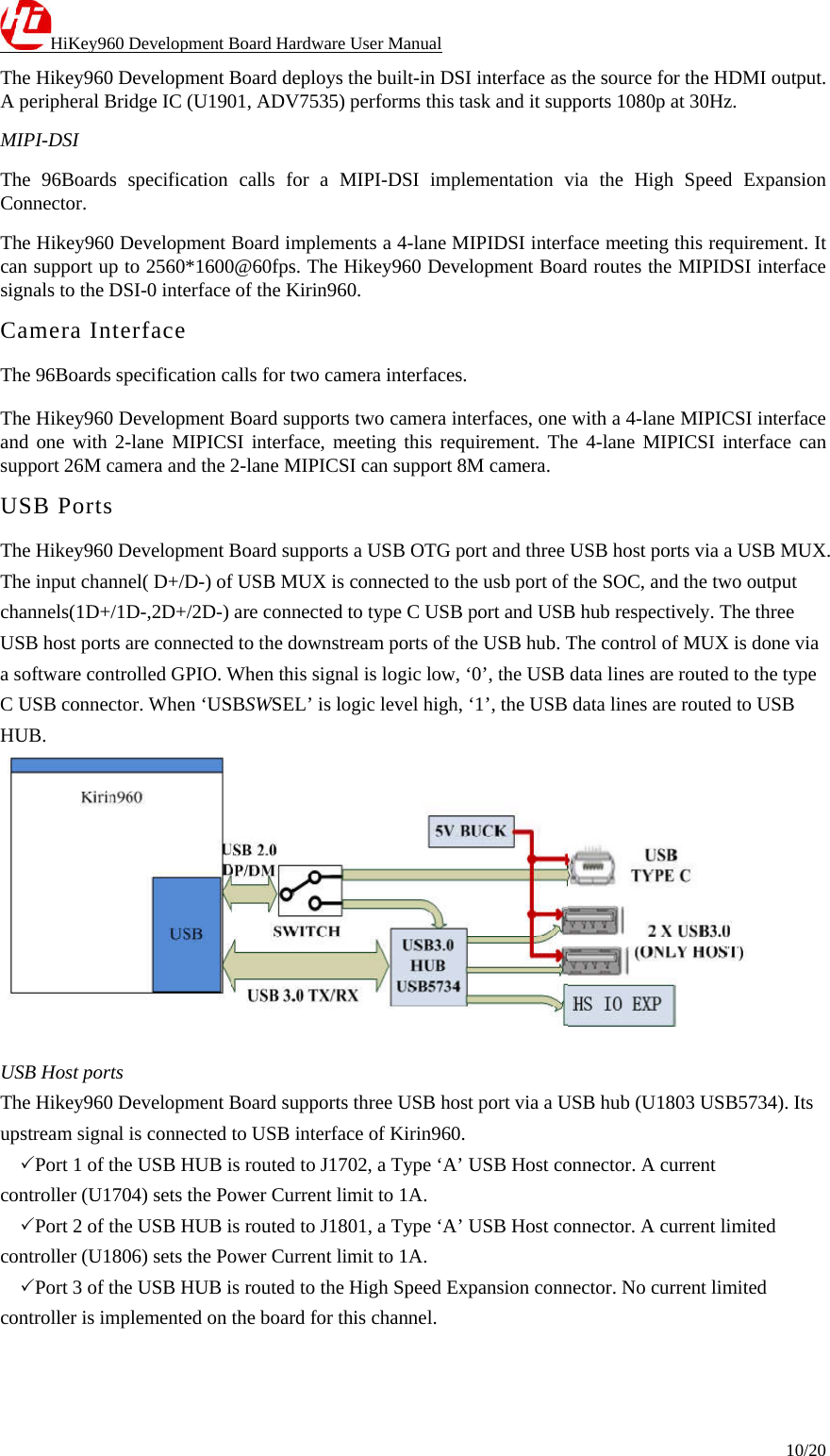
Wiki Guide
HTML
PDF
Info
Views
User Manual
Discussion / Help
Navigation