Huawei Technologies HIKEY960 Hikey960 User Manual QISHIKEY960 User Manualx
Huawei Technologies Co.,Ltd Hikey960 QISHIKEY960 User Manualx
Contents
- 1. User_Manual
- 2. user_manual
- 3. Uaser_Manual
User_Manual
HiKey960 Development Board Hardware User Manual
1/20
HiKey960 Development
Board Hardware User
Manual
Version 1.0

HiKey960 Development Board Hardware User Manual
2/20
Table of Contents
Table of Contents ....................................................................................................................................... 2
Introduction ................................................................................................................................................ 3
What’s in the Box ....................................................................................................................................... 4
Board Overview.......................................................................................................................................... 5
Key Components ........................................................................................................................................ 6
System Block Diagram ............................................................................................................................... 7
Getting Started ............................................................................................................................................ 8
Prerequisites ........................................................................................................................................... 8
Starting the board for the first time ........................................................................................................ 8
Component Details ..................................................................................................................................... 9
Processor ................................................................................................................................................ 9
PMIC ...................................................................................................................................................... 9
Memory (DRAM) .................................................................................................................................. 9
Storage ................................................................................................................................................... 9
Micro SDHC .......................................................................................................................................... 9
Boot ROM .............................................................................................................................................. 9
Networking ............................................................................................................................................. 9
WiFi ....................................................................................................................................................... 9
Display Interface .................................................................................................................................... 9
Camera Interface .................................................................................................................................. 10
USB Ports ............................................................................................................................................. 10
Audio .................................................................................................................................................... 11
DC Power ............................................................................................................................................. 11
Power Measurement ............................................................................................................................. 11
External Fan Connection ...................................................................................................................... 11
UART ................................................................................................................................................... 11
Buttons ................................................................................................................................................. 11
LED Indicators ..................................................................................................................................... 11
Additional Functionality ...................................................................................................................... 12
Expansion Connectors .............................................................................................................................. 13
Low Speed Expansion Connector ........................................................................................................ 13
High Speed Expansion Connector ........................................................................................................ 14
Power Management Overview ................................................................................................................. 17
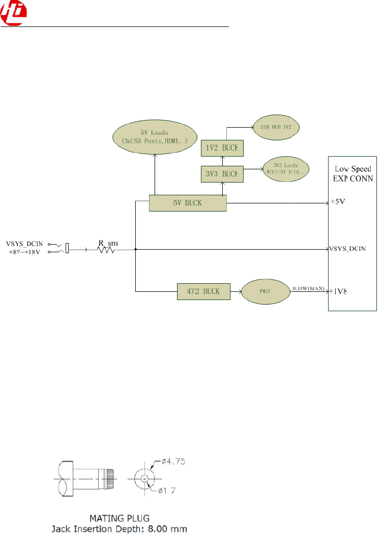
Block Diagram ..................................................................................................................................... 17
DC Power Input ................................................................................................................................... 17
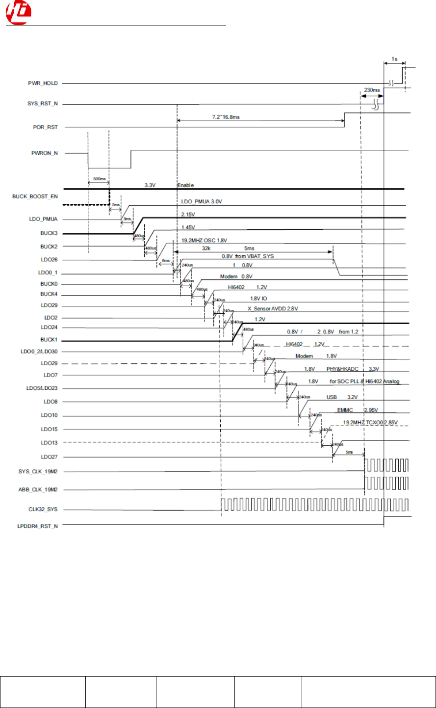
Power-on Sequence .............................................................................................................................. 17
Voltage Rails ........................................................................................................................................ 18
Mechanical specification .......................................................................................................................... 20
HiKey960 Development Board Hardware User Manual
3/20
Introduction
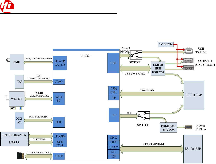
The HiKey960 Development Board is a 96Boards compliant community board based on Hisilicon
Kirin960 SoC. The following table lists its key features:
Processor Kirin 960 SoC
4x Cortex-A73 @ 2.4GHz
4x Cortex-A53 @ 1.8GHz
ARM Mali-G71 MP8 900MHz
Memory/
Storage
32GB UFS flash storage
MicroSD card slot
PCIE Gen2 on M.2 Key connector
Wireless WiFi (2.4- and 5-GHz dual band with two antennas)( DFS band not support)
Bluetooh not support
USB 2 x USB 3.0 type A (host mode only)
1 x USB 2.0 type C OTG
Display 1 x HDMI 1.4 (Type A - full)
1 x 4L-MIPI DSI
HDMI output up to FHD 1080P
Video Inside Encoder:H.265/H.264 3840*2400@30fps 4 * 1080p @ 30 fps
Inside Decoder: H.265,HEVC MP/High Tier, Main 10/High
Tier,H.264BP/MP/HP, MPEG1/2/4, VC-1, VP6/8
Audio HDMI output
Camera 1 x 4-lane MIPI CSI
1 x 2-lane MIPI CSI
Expansion
Interface
40 pin low speed expansion connector: +1.8V, +5V, DC power,GND,2UART,
2I2C, SPI, I2S, 12*GPIO60 pin high speed expansion connector: 4L-MIPI
DSI, I2C x2, SPI (48M),USB 2.0, 2L+4LMIPI CSI
LED 1 x WiFi activity LED(Yellow)
1 x Activity LED (Blue)
4 x User LEDs (Green)
Button Power Button :Button Power on/off & Reset the system
Power Source Recommend a 12V@2A adapter with a DC plug which has a 4.75mm outerb
diameter and 1.7mm center pin with standard center-positive
(EIAJ-3Compliant)
OS Support AOSP/LINUX
Appearance
characteristic 85mm x 55mm
HiKey960 Development Board Hardware User Manual
4/20
What’s in the Box
The box contains one HiKey960 Development Board and a quick start guide.
HiKey960 Development Board Hardware User Manual
5/20
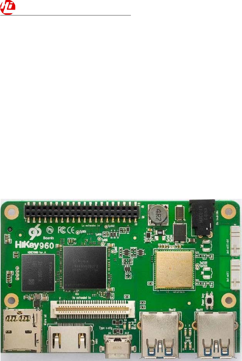
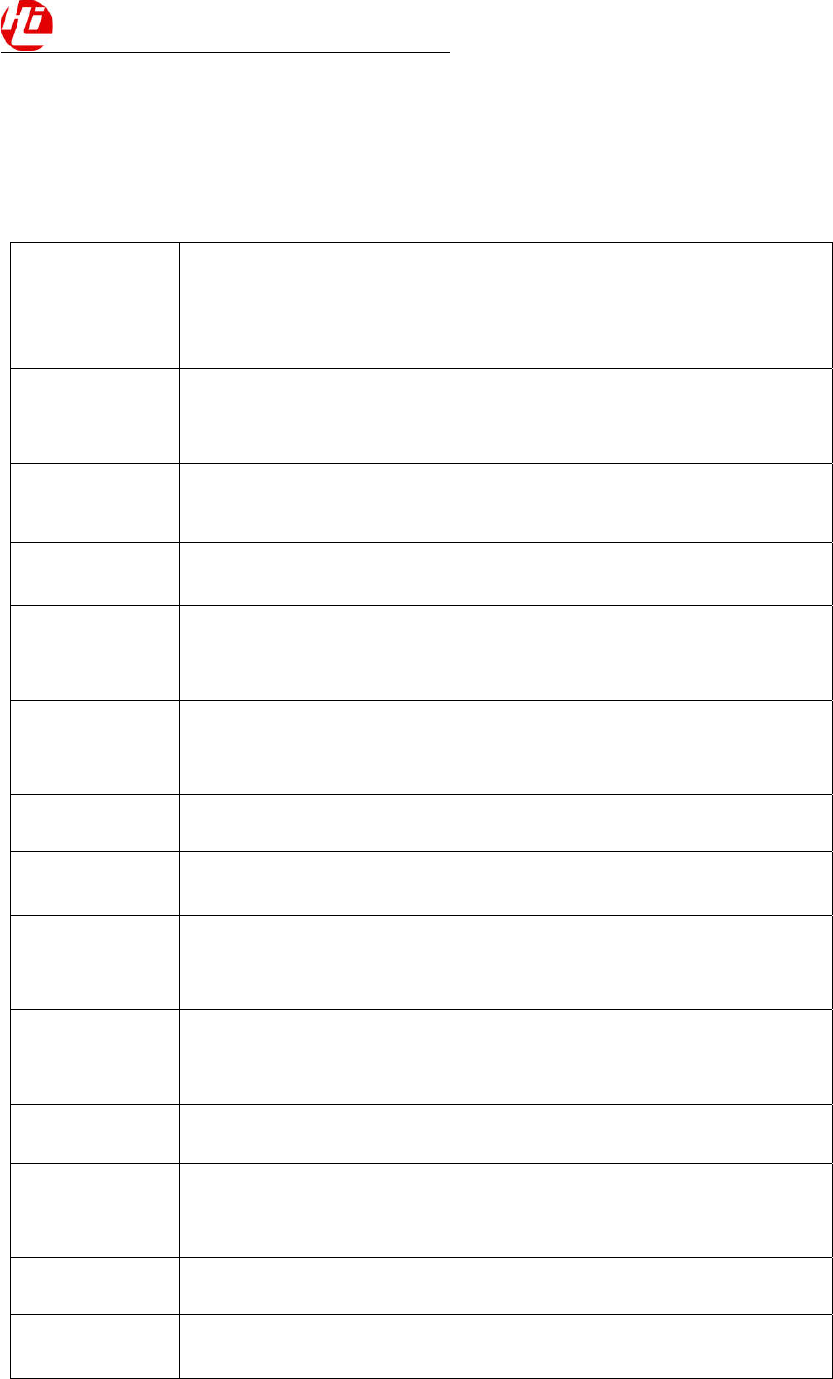
Board Overview
HiKey960 Development Board Hardware User Manual
6/20
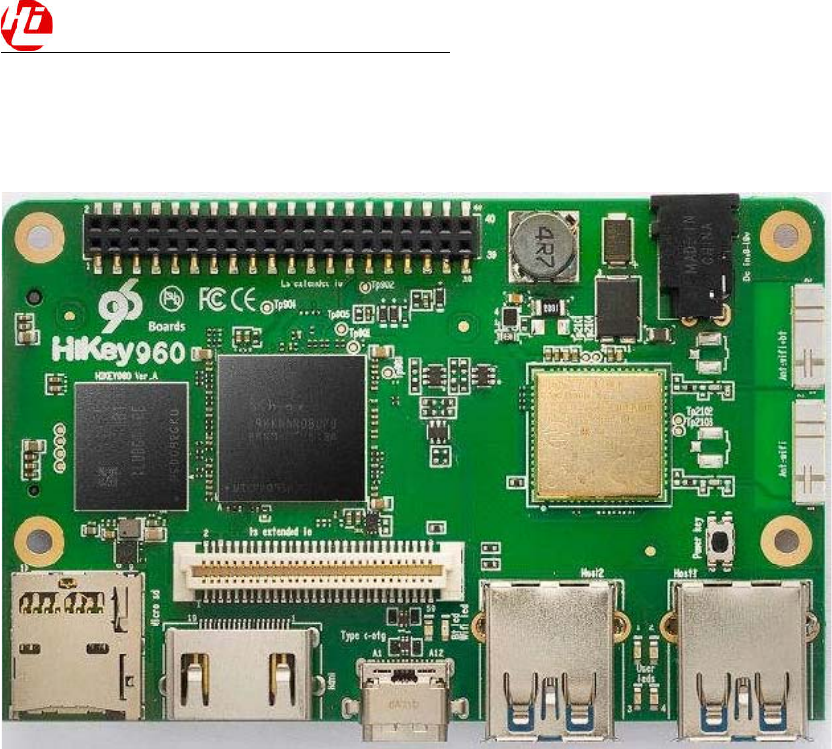
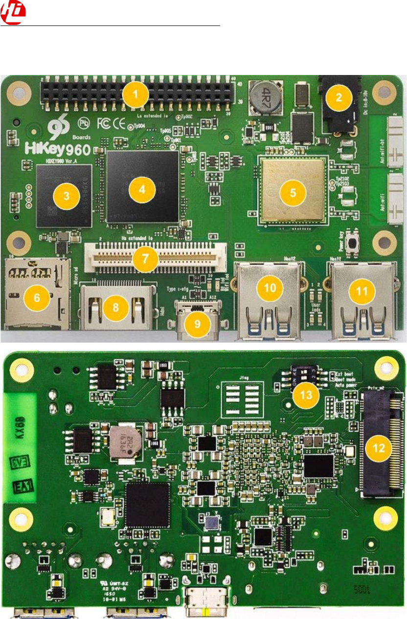
Key Components
Position Reference Description
1 J2002 Low Speed Expansion Connector
2 P401 DC Input 8-18V
3 U1601 UFS 32GB
4 U501 Kirin960 & 3GB LPDDR4
5 U2101 WLAN
6 P2301 Micro SD Card Socket
7 J2001 High Speed Connector
8 J1901 HDMI Type A Port
9 J1701 USB Type C Connector
10 J1801 USB3.0 Host2 Connector
11 J1702 USB3.0 Host1 Connector
12 J2501 PCI-E
13 SW2201
Auto Power Boot SEL
HiKey960 Development Board Hardware User Manual
7/20
System Block Diagram

HiKey960 Development Board Hardware User Manual
8/20
Getting Started
Prerequisites
Before you power up your HiKey960 Development Board for the first time you will need the following:
HiKey960 Development Board.
A 96Boards compliant power supply (sold separately ).
A HDMI or DVI LCD Monitor that supports a resolution of 1080P/60Hz.
HDMI-HDMI cable or HDMI-DVI cable to connect the board to the Monitor.
A computer keyboard with USB interface.
A computer mouse with USB interface.
Starting the board for the first time
To start the board, follow these simple steps:
step1. Connect the HiKey960 to your display with the HDMI cable. It is important to do this first
becausethe monitor will not detect the board if it is connected after starting. Ensure that the source for
the displayis switched to the HDMI port you are using.
step2. Connect the Express-UartBoard.
step3. Ensure Auto Power is ON.

HiKey960 Development Board Hardware User Manual
9/20
Component Details
Processor
4 ARM Cortex-A73 MPCore(Big Core 4 2.4G Hz) 4 A53 MPCore(Little Core 1.8G)
ARM Mali G71 MP8 3DGPU
PMIC
There are a master PMIC and two slave PMIC for Kirin960 platform.
Master PMIC is a power management system chip.
One of the slave PMIC is a 4-phase high efficiency buck converter which applied to offer the power of
CPU-B, and the other one is used for GPU&CPU-L.
Memory (DRAM)
The Hikey960 Development Board provides 3GB LPDDR4-SDRAM which is a 4-channel and 64bit
width bus implementation interfacing directly to the Kirin960 build-in LPDDR controller. The maximum
DDR clock is 1866MHz. It is mounted over the Kirin960 using pop technology.
Storage
The Hikey960 Development Board provides an 32GB UFS which is compliant with UFS2.0.
Micro SDHC
The Hikey960 Development Board SD slot signals are routed directly to the Kirin960 SDC interface. It
meets the SD3.0 standard.
Boot ROM
The Hikey960 Development Board boots up from the UFS.
Networking
WiFi
Dual-band (2.4/5GHz) single stream 802.11 a/b/g/n RF.
20- and 40-MHz SISO and 20-MHz 2 × 2 MIMO at 2.4 GHz for High Throughput: 80 Mbps(TCP),
100 Mbps (UDP).
2.4-GHz MRC Support for Extended Range and 5-GHz Diversity Capable.
Display Interface
HDMI
The 96Boards specification calls for an HDMI port to be present on the board. The Kirin960 doesn’t
include a built-in HDMI interface.
HiKey960 Development Board Hardware User Manual
10/20
The Hikey960 Development Board deploys the built-in DSI interface as the source for the HDMI output.
A peripheral Bridge IC (U1901, ADV7535) performs this task and it supports 1080p at 30Hz.
MIPI-DSI
The 96Boards specification calls for a MIPI-DSI implementation via the High Speed Expansion
Connector.
The Hikey960 Development Board implements a 4-lane MIPIDSI interface meeting this requirement. It
can support up to 2560*1600@60fps. The Hikey960 Development Board routes the MIPIDSI interface
signals to the DSI-0 interface of the Kirin960.
Camera Interface
The 96Boards specification calls for two camera interfaces.
The Hikey960 Development Board supports two camera interfaces, one with a 4-lane MIPICSI interface
and one with 2-lane MIPICSI interface, meeting this requirement. The 4-lane MIPICSI interface can
support 26M camera and the 2-lane MIPICSI can support 8M camera.
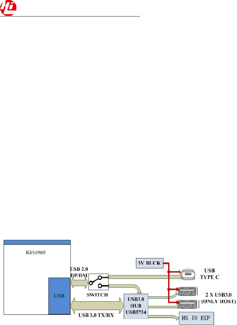
USB Ports
The Hikey960 Development Board supports a USB OTG port and three USB host ports via a USB MUX.
The input channel( D+/D-) of USB MUX is connected to the usb port of the SOC, and the two output
channels(1D+/1D-,2D+/2D-) are connected to type C USB port and USB hub respectively. The three
USB host ports are connected to the downstream ports of the USB hub. The control of MUX is done via
a software controlled GPIO. When this signal is logic low, ‘0’, the USB data lines are routed to the type
C USB connector. When ‘USBSWSEL’ is logic level high, ‘1’, the USB data lines are routed to USB
HUB.
USB Host ports
The Hikey960 Development Board supports three USB host port via a USB hub (U1803 USB5734). Its
upstream signal is connected to USB interface of Kirin960.
Port 1 of the USB HUB is routed to J1702, a Type ‘A’ USB Host connector. A current
controller (U1704) sets the Power Current limit to 1A.
Port 2 of the USB HUB is routed to J1801, a Type ‘A’ USB Host connector. A current limited
controller (U1806) sets the Power Current limit to 1A.
Port 3 of the USB HUB is routed to the High Speed Expansion connector. No current limited
controller is implemented on the board for this channel.
HiKey960 Development Board Hardware User Manual
11/20
USB OTG ports
The Hikey960 Development Board implements a OTG port. The port is located at J1701, a type C USB.
Note: the board can work in one mode at a time, Host mode or Device mode, not both.
Audio
The Hikey960 Development Board has two audio ports: HDMI and I2S.
DC Power
The Hikey960 Development Board can be powered as follow:
8V to 18V supply from a dedicated DC jack(P401)
Power Measurement
The Hikey960 Development Board has three current sense resistors R401/R413/R408.
Reference Net Description
R401 DCIN To measure the current of total base board power
R413 SYS5V To measure the current of SYS_5V power
R408 VCC4V2 To measure the current of VDD4V2 power
External Fan Connection
The 96Boards specification calls for support for an external fan. That can be achieved by using the 5V
orthe SYS_DCIN (12V), both present on the Low Speed Expansion connector.
UART
The Hikey960 Development Board has two UART ports (UART6 / UART3), both present on the Low
Speed Expansion connector. They are routed to the UART6 (UART1TxD, UART1RxD) and UART3
(UART3TxD, UART3RxD, UART3CTS, UART3RTS) interface of Kirin960 separately. The UART6
isused for the serial console output.
Buttons
The Hikey960 Development Board presents one button. It is Power key which also can be used as
Resetkey. The power ON/OFF and RESET signals are also routed to the Low Speed Expansion
connector.
Power Button
The push-button S2201 serves as the power-on/sleep button. Upon applying power to the board, press
thepower button the board will boot up. Once the board is running you can turn power-off by pressing
thepower button for more than 3 seconds. If the board is in a sleep mode, pressing the power bottom
willwake up the board. Oppositely, if the board is in an active mode, pressing the power bottom will
changethe board into sleep mode.
Reset Button
The push-button S2201 also serves as the hardware reset button. press the button for more than 10
seconds,the system will be rebooted.
LED Indicators
The MediaTek X20 Professional Board has six LEDs.

HiKey960 Development Board Hardware User Manual
12/20
Two activity LEDs:
WiFi activity LED –The Hikey960 Development Board drives this Yellow LED via GPIO205
fromKirin960.
Activity LED –The Hikey960 Development Board drives this Blue LED via GPIO207
fromKirin960.
Four User LEDs:
The four user LEDs are surface mount Green in 0603 size located next to the USB type A connector.
TheHikey960 Development Board drives the four LEDs from the soc GPIO: GPIO150, GPIO151,
GPIO189and GPIO190.
Additional Functionality
The Hikey960 Development Board also has a additional interface for user debugging. It includes JTAG
interface. The position is reserved, but the component is not mounted in the mass production.
HiKey960 Development Board Hardware User Manual
13/20
Expansion Connectors
Low Speed Expansion Connector
The following tables show the Low Speed Expansion Connector pin out:
HiKey960 Signals 96Boards Signals PIN PIN 96Boards Signals HiKey960 Signals
GND GND 1 2 GND GND
UART3CTSN UART0CTS 3 4 PWRBTNN PWRONN
UART3TXD UART0TxD 5 6 RSTBTNN EXPRSTOUTN
UART3RXD UART0RxD 7 8 SPI0SCLK SPI1CLK
UART3RTSN UART0RTS 9 10 SPI0DIN SPI1DI
UART5TXD UART1TxD 11 12 SPI0CS SPI1CSN
UART5RXD UART1RxD 13 14 SPI0DOUT SPI1DO
I2C0SCL I2C0SCL 15 16 PCMFS CODECSSIDATA
I2C0SDA I2C0SDA 17 18 PCMCLK SLIMBUSCLK
I2C7SCL I2C1SCL 19 20 PCMDO SLIMBUSDATA
I2C7SDA I2C1SDA 21 22 PCMDI GPIO045CODECRST
GPIO215 GPIO-A 23 24 GPIO-B GPIO216
GPIO217 GPIO-C 25 26 GPIO-D GPIO218
GPIO220 GPIO-E 27 28 GPIO-F LCDBLPWM
LCDTE0 GPIO-G 29 30 GPIO-H GPIO040LCDRSTN
GPIO052CAM0RSTN GPIO-I 31 32 GPIO-J CAMPDN0
GPIO075CAM1RSTN GPIO-K 33 34 GPIO-L CAMPDN1
VOUT111V8/2V95 +1V8 35 36 SYSDCIN SYSDCIN
SYS_5V +5V 37 38 SYCDCIN SYSDCIN
GND GND 39 40 GND GND
UART {3/6}
The 96Boards specifications calls for a 4-wire UART implementation, UART0 and an optimal second
2-wire UART, UART1 on the Low Speed Expansion Connector.The HiKey960 Development Board
implements UART3 as a 4-wire UART that connects directly to theMT6797 SoC. These signals are
driven at 1.8V.The HiKey960 Development Board implements UART6 as a 2-wire UART that connects
directly to theMT6797 SoC. These signals are driven at 1.8V.
I2C {0/1}
The 96Boards specification calls for two I2C interfaces to be implemented on the Low Speed Expansion
Connector.
The HiKey960 Development Board implements both interfaces named I2C0 and I2C7. They connect
directly to the Kirin960 SoC. Each of the I2C lines is pulled up to VIO18_PMU via 1K resistor.
GPIO {A-L}

HiKey960 Development Board Hardware User Manual
14/20
The 96Boards specification calls for 12 GPIO lines to be implemented on the Low Speed Expansion
Connector. Some of these GPIOs may support alternate functions for DSI/CSI controlThe HiKey960
Board implements this requirement. All GPIOs are routed to the Kirin960 SoC. Take LowSpeed
Expansion Connector for reference.
SPI 0
The 96Boards specification calls for one SPI bus master to be provided on the Low Speed Expansion
Connector.
The HiKey960 Development Board implements a full SPI master with 4 wires, CLK, CS, MOSI and
MISO. The signals are connected directly to the Kirin960 SoC and driven at 1.8V.
I2S
The 96Boards specification calls for one PCM/I2S bus to be provided on the Low Speed Expansion
Connector. The CLK, FS and DO signals are required while the DI is optional.
The HiKey960 Development Board implements a I2S interface with 4 wires, CLK, FS, DO and DI. The
signals are connected directly to the Kirin960 SoC and driven at 1.8V.
Power and Reset
The 96Boards specification calls for a signal on the Low Speed Expansion Connector that can power
on/off the board and a signal that serves as a board reset signal.
The HiKey960 Development Board routes the PWRBTNN (named PWRKEY on schematic) signal to
thePWRKEY pin of the PMIC. This signal is driven by s2201 as well, the on-board power on
push-buttonswitch. A mezzanine implementation of this signals should not drive it with any voltage, the
only allowedoperation is to force it to GND to start the board from a sleep mode.
The HiKey960 Development Board routes the RSTBTNN (named exp_rstoutn on schematic) signal to
the HRESETN pin of the PMIC Hi6421.
Power Supplies
The 96Boards specification calls for three power rails to be present on the Low Speed Expansion
Connector:
+1.8V Max of 100mA
+5V Provide a minimum of 5W of power (1A).
SYS_DCIN 8-18V input with enough current to support all the board functions or the output
DCIN from on-board DC Connector able to provide a minimum of 7W of power.
The HiKey960 Development Board supports these requirements as follows:
+1.8V Driven by PMIC up to 150mA.
+5V Driven by a 5A DC-DC buck converter (U403). It also provides the VBUS power to
the twoUSB host connectors (J1702, J1801) and the HDMI 5V power to the HDMI connector
(J1901).Theremaining capacity provides a total of 7W which meets the 96Boards requirements.
High Speed Expansion Connector
There is a 60-pin High Speed Expansion Connector on board. As shown in the table below.
HiKey960 Signals 96Boards Signals PIN PIN HiKey960 Signals 96Boards Signals
HiKey960 Development Board Hardware User Manual
15/20
GPIO148SPI3DO SDDAT0/SPI1DOUT 1 2 CSI0C+ CSI0CLKP
UART0IRDARXD SDDAT1 3 4 CSI0C- CSI0CLKN
UART0IRDATXD SDDAT2 5 6 GND GND
GPIO149SPI3CS0N SDDAT3/SPI1CS 7 8 CSI0D0+ CSI0DATA0P
GPIO146SPI3CLK SDSCLK/SPI1SCLK 9 10 CSI0D0- CSI0DATA0N
GPIO147SPI3DI SDCMD/SPI1DIN 11 12 GND GND
GND GND 13 14 CSI0D1+ CSI0DATA1P
ISPCCLK0MCAM CLK0/CSI0MCLK 15 16 CCSI0D1- CSI0DATA1N
ISPCCLK1SCAM CLK1/CSI1MCLK 17 18 GND GND
GND GND 19 20 CSI0D2+ CSI0DATA2P
DSI2CLKP DSICLK+ 21 22 CSI0D2- CSI0DATA2N
DSI2CLKN DSICLK- 23 24 GND GND
GND GND 25 26 CSI0D3+ CSI0DATA3P
DSI2DATA0P DSID0+ 27 28 CSI0D3- CSI0DATA3N
DSI2DATA0N DSID0- 29 30 GND GND
GND GND 31 32 I2C2SCL ISPSCL0
DSI2DATA1P DSID1+ 33 34 I2C2SCL ISPSDA0
DSI2DATA1N DSID1- 35 36 I2C3SDA ISPSCL1
GND GND 37 38 I2C3SDA ISPSDA1
DSI2DATA2P DSID2+ 39 40 GND GND
DSI2DATA2N DSID2- 41 42 CSI1D0+ CSI1DATA0P
GND GND 43 44 CSI1D0- CSI1DATA0N
DSI2DATA3P DSID3+ 45 46 GND GND
DSI2DATA3N DSID3- 47 48 CSI1D1+ CSI1DATA1P
GND GND 49 50 CSI1D1- CSI1DATA1N
USB2DNDP4CON USBD+ 51 52 GND GND
USB2DNDM4CON USBD- 53 54 CSI1C+ CSI1CLKP
GND GND 55 56 CSI1C- CSI1CLKN
NC HSICSTR 57 58 GND GND
NC HSICDATA 59 60 RESERVED Pull-up vout21v8
MIPI DSI {0}
The 96Boards specification calls for a MIPI-DSI to be present on the High Speed Expansion Connector.
A minimum of one lane is required and up to four lanes can be accommodated on the connector. The
Hikey960 Development Board implementation supports a full four lane (1.2Gbps/lane) MIPI-DSI
interface that is routed to the High Speed Expansion Connector. The MIPI-DSI signals are directly
connected to DSI-0 of Kirin960.

HiKey960 Development Board Hardware User Manual
16/20
MIPI CSI {0/1}
The 96Boards specification calls for two MIPI-CSI interfaces to be present on the High Speed
ExpansionConnector. Both interfaces are optional. CSI0 interface can be up to four lanes while CSI1 is
up to twolanes.
The Hikey960 Development Board implementation supports a full four lane MIPI-CSI interface on CSI0
and two lanes of MIPI-CSI on CSI1. All MIPI-CSI signals are routed directly to/from the Kirin960 SoC.
CSI0 can support up to 26M@30fps and CSI1 can support up to 8M@30fps. The max data rate of each
lane is 2.5Gbps.
I2C {2/3}
The 96Boards specification calls for two I2C interfaces to be present on the High Speed Expansion
Connector. Both interfaces are optional unless a MIPI-CSI interface has been implemented. Then an I2C
interface shall be implemented.
The Hikey960 Development Board implementation supports two MIPI-CSI interfaces and therefore
mustsupport two I2C interfaces,they are ISPI2C0 and ISPI2C1. Each of the I2C lines is pulled up to
VIO18_PMU via 1K resistor.
SD/SPI
The 96Boards specification calls for an SD interface or a SPI port to be part of the High Speed
ExpansionConnector.
The Hikey960 Development Board implements a full SPI master with 4 wires (96Boards SPI
Configuration), CLK, CS, MOSI and MISO. All the signals are connected directly to the Kirin960 SoC.
These signals are driven at 1.8V.
Clocks
The 96Boards specification calls for one or two programmable clock interfaces to be provided on the
High Speed Expansion Connector. These clocks may have a secondary function of being CSI0MCLK
andCSI1MCLK. If these clocks can’t be supported by the SoC than an alternative GPIO or No-Connect
isallowed by the specifications.
The Hikey960 Development Board implements two CSI clocks which are connected directly to the
Kirin960 SoC. These signals are driven at 1.8V.
USB
The 96Boards specification calls for a USB Data line interface to be present on the High Speed
ExpansionConnector.
The Hikey960 Development Board implements this requirement by routing USB channel 4 from the
USBHUB to the High Speed Expansion Connector.
HSIC
The 96Boards specification calls for an optional MIPI-HSIC interface to be present on the High Speed
Expansion Connector.
The Hikey960 Development Board implementation doesn’t support this optional requirement.
Reserved
The pin 60 of the High Speed Expansion Connector is pulled up to VIO18_PMU via 100K resistor.
Po
w
Bl
o
DC
N
ot
e
1.7
m
and
t
Po
w
HiKey960
D
w
er
Man
a
o
ck Diagr
a
Power In
An 8V t
o
An 8V t
o
CON70
0
e
: Please refe
r
mm
,the oute
r
t
he negative
p
w
er-on Se
q
D
evelopment B
o
ag
ement
O
v
a
m
put
o
18V power
f
o
18V power
f
0
1.
r
to the mech
a
r
diameter of
t
p
ole is outsid
e
q
uence
o
ard Hardware
U
v
erview
f
rom a dedica
t
f
rom the SYS
_
a
nical size of
t
t
he plug is 4.
7
e
.
U
ser Manual
t
ed DC jack J
9
_
DCIN pins
o
t
he DC plug b
7
5mm.The po
s
9
01.
o
n the Low S
p
elow. The ins
s
itive electro
d
p
eed Expansi
o
ide diameter
o
d
e of the DC
p
o
n Connector
o
f the plug is
p
lug is in the
i
17/20
i
nside,
HiKey960 Development Board Hardware User Manual
18/20
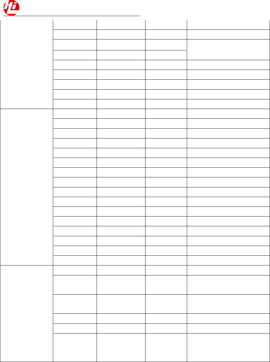
Voltage Rails
Circuit Type Net Name Default ON
Voltage(V)
Iout Max
(mA) Expected use
HiKey960 Development Board Hardware User Manual
19/20
BUCK
SYS5V 5 5000 system 5V
VDD4V2 4.2 5000 system power
VDDCPUB 0.8 16000
4Cortex A73
4Cortex A53
VDDCPUL 1.05 30000
VDDGPU 0.8 12000 Core power for GPU
Vbuck00V8 0.8 2500 core power for PERI
Vbuck11V1 1.1 3000 DRAM and LDO
Vbuck21V45 1.45 2500 power for LDO
Vbuck32V15 2.15 2500 power for LDO
LDO
LDO0 0.8 300 UFS,sys
LDO1 1.29 300 HDMI V1P2
LDO2 1.8 800 1.8V IO
LDO3 1.85 300 HDMI
LDO5 1.8 500 MIPI phy,DDR phy,HKADC
LDO7 1.8 300 ABB,PLL
LDO8 1.8 300 sys PLL
LDO9 1.8/2.95 150 SD card IO
LDO10 3.2 100 USB phy 3.3V
LDO11 1.8 150 40 pin connector
LDO15 3 600 UFS
LDO16 2.95 800 SD card
LDO21 1.8 200 efusesys
LDO26 1.8 50 19.2M XO
LDO29 1.2 200 UFS 1.2V
LDO30 0.8 300 UFS 0.8V
Other
HDMI5V 5 HDMI output voltage
VBUSHOST1 5
USB host1 output
voltage(CON6401)
VBUSHOST2 5
USB host2 output
voltage(CON6402)
VIO18PMU 1.8 1.8V on LS connector
SYS5V 5 5V on LS connector
DCIN 8 ~ 18
8-18V DCIN on LS connector
as
output
HiKey960 Development Board Hardware User Manual
20/20
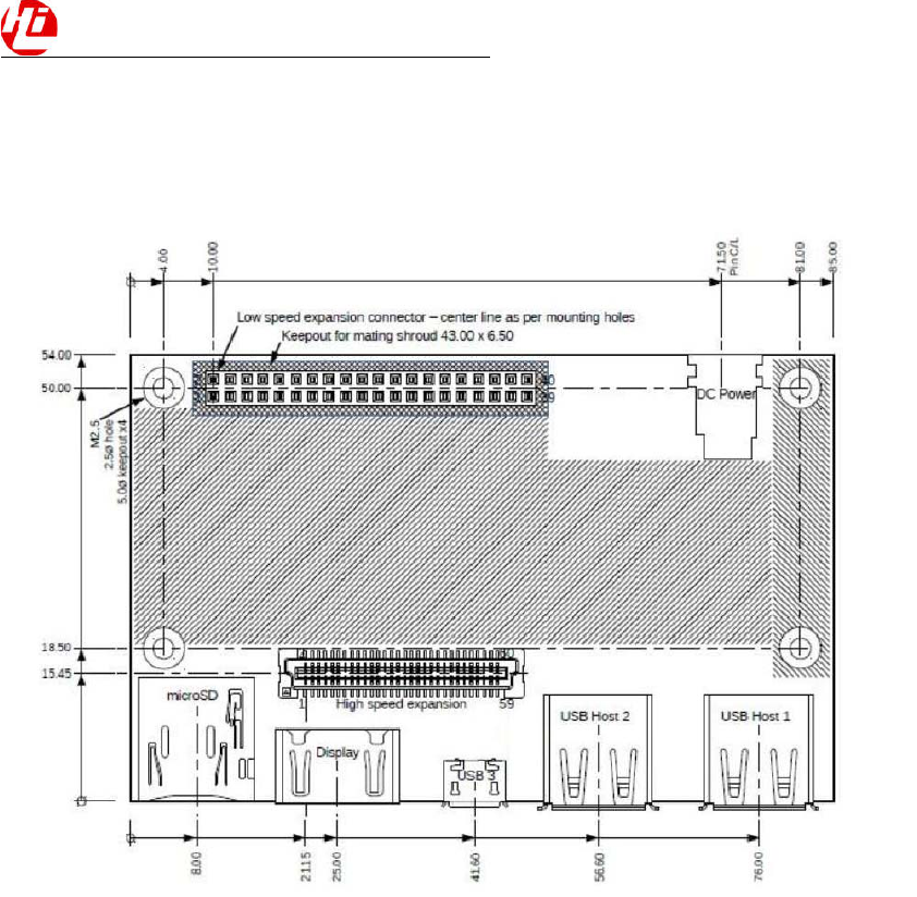
Mechanical specification
The Hikey960 Development Board is compliant with the 96boards mechanical specification.
FCC Regulations:
This device complies with part 15 of the FCC Rules. Operation is subject to the
following two conditions: (1) This device may not cause harmful interference, and
(2) this device must accept any interference received, including interference that
may cause undesired operation.
This equipment has been tested and found to comply with the limits for a Class B
digital device, pursuant to part 15 of the FCC Rules. These limits are designed to
provide reasonable protection against harmful interference in a residential
installation. This equipment generates, uses and can radiate radio frequency energy
and, if not installed and used in accordance with the instructions, may cause
harmful interference to radio communications. However, there is no guarantee that
interference will not occur in a particular installation. If this equipment does cause

HiKey960 Development Board Hardware User Manual
21/20
harmful interference to radio or television reception, which can be determined by
turning the equipment off and on, the user is encouraged to try to correct the
interference by one or more of the following measures:
—Reorient or relocate the receiving antenna.
—Increase the separation between the equipment and receiver.
—Connect the equipment into an outlet on a circuit different from that to which the
receiver is connected.
—Consult the dealer or an experienced radio/ TV technician for help.
Changes or modifications not expressly approved by the manufacturer could void
the user’s authority to operate the equipment.
FCC RF Radiation Exposure Statement
This equipment complies with FCC radiation exposure limits set forth for an
uncontrolled environment. To comply with FCC RF Exposure compliance
requirements, this grant is applicable to only Mobile Configurations. The antennas
used for the transmitter must be installed to provide a separation distance of at least
20cm from all persons and must not be co-located or operating in conjunction with any
other antenna or transmitter.