Huawei Technologies ODU3601C-1900 CDMA Base Station User Manual 1
Huawei Technologies Co.,Ltd CDMA Base Station Users Manual 1
Contents
Users Manual 1
HUAWEI
iSiteC ODU3601C CDMA Soft Base Station
Installation Manual
V100R001

iSiteC ODU3601C CDMA Soft Base Station
Installation Manual
Manual Version T2-030400-20030702-C-1.10
Product Version V100R001
BOM 31040900
Huawei Technologies Co., Ltd. provides customers with comprehensive technical support
and service. Please feel free to contact our local office, customer care center or company
headquarters.
Huawei Technologies Co., Ltd.
Address: Administration Building, Huawei Technologies Co., Ltd.,
Bantian, Longgang District, Shenzhen, P. R. China
Postal Code: 518129
Website: http://www.huawei.com
Email: support@huawei.com

Copyright © 2003 Huawei Technologies Co., Ltd.
All Rights Reserved
No part of this manual may be reproduced or transmitted in any form or by any
means without prior written consent of Huawei Technologies Co., Ltd.
Trademarks
, HUAWEI, C&C08, EAST8000, HONET, , ViewPoint, INtess, ETS, DMC,
TELLIN, InfoLink, Netkey, Quidway, SYNLOCK, Radium, M900/M1800,
TELESIGHT, Quidview, Musa, Airbridge, Tellwin, Inmedia, VRP, DOPRA, iTELLIN,
HUAWEI OptiX, C&C08 iNET, NETENGINE, OptiX, SoftX, iSite, U-SYS, iMUSE,
OpenEye, Lansway, SmartAX are trademarks of Huawei Technologies Co., Ltd.
All other trademarks mentioned in this manual are the property of their respective
holders.
Notice
The information in this manual is subject to change without notice. Every effort has
been made in the preparation of this manual to ensure accuracy of the contents, but
all statements, information, and recommendations in this manual do not constitute
the warranty of any kind, express or implied.

About This Manual
Version
The product version corresponds to the manual is iSiteC ODU3601C CDMA Soft Base
Station V100R001.
Organization of the Manual
This manual introduces the installation procedure of Huawei iSiteC ODU3601C CDMA
Soft Base Station, covering the preparations before installation, introduction to
hardware components, installation steps of the equipment and auxiliary devices,
installation inspection and the system commissioning.
Intended Readers
The manual is intended for the following readers:
l Installation engineers & technicians
l Operation & maintenance personnel
Conventions
This manual uses the following conventions:
I. General conventions
Convention Description
Arial Normal paragraphs are in Arial.
Arial Narrow Warnings, Cautions, Notes and Tips are in Arial Narrow.
Boldface Headings are in Boldface.
Courier New Terminal Display is in Courier New.
II. Command conventions
Convention Description
Boldface The keywords of a command line are in Boldface.

Convention Description
Boldface The keywords of a command line are in Boldface.
italic Command arguments are in italic.
[ ] Items (keywords or arguments) in square brackets [ ] are optional.
{ x | y | ... } Alternative items are grouped in braces and separated by vertical bars. One is
selected.
[ x | y | ... ] Optional alternative items are grouped in square brackets and separated by
vertical bars. One or none is selected.
{ x | y | ... } * Alternative items are grouped in braces and separated by vertical bars. A minimum
of one or a maximum of all can be selected.
[ x | y | ... ] * Optional alternative items are grouped in square brackets and separated by
vertical bars. Many or none can be selected.
III. GUI conventions
Convention Description
< > Button names are inside angle brackets. For example, click <OK> button.
[ ] Window names, menu items, data table and field names are inside square
brackets. For example, pop up the [New User] window.
/ Multi-level menus are separated by forward slashes. For example,
[File/Create/Folder].
IV. Keyboard operation
Format Description
<Key> Press the key with the key name inside angle brackets. For example, <Enter>,
<Tab>, <Backspace>, or <A>.
<Key1+Key2> Press the keys concurrently. For example, <Ctrl+Alt+A> means the three keys
should be pressed concurrently.
<Key1, Key2> Press the keys in turn. For example, <Alt, A> means the two keys should be
pressed in turn.
V. Mouse operation
Action Description
Click Press the left button or right button quickly (left button by default).
Double Click Press the left button twice continuously and quickly.
Drag Press and hold the left button and drag it to a certain position.

VI. Symbols
Eye-catching symbols are also used in the manual to highlight the points worthy of
special attention during the operation. They are defined as follows:
Caution, Warning, Danger: Means reader be extremely careful during the
operation.
& Note, Comment, Tip, Knowhow, Thought: Means a complementary description.
Environmental Protection
This product has been designed to comply with the requirements on environmental
protection. For the proper storage, use and disposal of this product, national laws and
regulations must be observed.

Installation Manual
iSiteC ODU3601C CDMA Soft Base Station Table of Contents
i
Table of Contents
Safety Precautions .............................................................................................................. S-1
1 Overview..................................................................................................................... S-1
1.1 Symbol Explanation ........................................................................................... S-2
2 Toxic Articles............................................................................................................... S-3
2.1 Beryllium Oxide ................................................................................................. S-3
2.2 Hydrochloride .................................................................................................... S-4
2.3 Hydrofluoride..................................................................................................... S-4
3 Electrical Safety........................................................................................................... S-4
3.1 High Voltage...................................................................................................... S-4
3.2 Power Cables .................................................................................................... S-5
3.3 Tools ................................................................................................................ S-5
3.4 Drilling .............................................................................................................. S-6
3.5 Thunderstorms .................................................................................................. S-6
3.6 Static Electricity ................................................................................................. S-6
3.7 Power Labels .................................................................................................... S-8
3.8 Leakage Current................................................................................................ S-8
3.9 Flammable Air Environment................................................................................ S-9
4 Batteries ..................................................................................................................... S-9
4.1 General Operations............................................................................................ S-9
4.2 Short Circuit.................................................................................................... S-10
4.3 Harmful Gases ................................................................................................ S-10
4.4 High Temperature............................................................................................ S-10
4.5 Acid Liquid...................................................................................................... S-11
4.6 Battery Replacement........................................................................................ S-11
5 Microwave and Magnetic Field ................................................................................... S-11
5.1 Introduction ..................................................................................................... S-11
5.2 Definition of the Environment............................................................................ S-12
5.3 Operation Codes ............................................................................................. S-12
6 Laser ........................................................................................................................ S-12
7 High Temperature...................................................................................................... S-13
8 Fans ......................................................................................................................... S-13
9 Working at High Altitudes ........................................................................................... S-14
9.1 General Operations.......................................................................................... S-14
9.2 Safety Codes for Using Ladders ....................................................................... S-14
10 Other Items ............................................................................................................. S-16
10.1 Hoisting of Heavy Objects .............................................................................. S-16
10.2 Handling of Heavy Objects ............................................................................. S-17

Installation Manual
iSiteC ODU3601C CDMA Soft Base Station Table of Contents
ii
10.3 Sharp Edges.................................................................................................. S-18
10.4 Inserting & Drawing Out the Boards ................................................................ S-18
10.5 Bundling the Signal Cables............................................................................. S-19
10.6 Maintenance and Commissioning by a Single Person is not Allowed ................. S-19
Installation Manual
iSiteC ODU3601C CDMA Soft Base Station Safety Precautions
S-1
Safety Precautions
1 Overview
This section covers part of the safety precautions to be observed during the
installation, maintenance, and the related operation of Huawei-developed network
equipment.
Caution:
Before any operation, please carefully go through the operation instructions and precautions so as to
prevent accidents. The signs such as "Caution, Attention, Warning and Danger" in manuals are merely
the supplements to safety precautions in operations rather than all the safety precautions to be observed.
Therefore, personnel engaged in the installation and maintenance of Huawei-developed products should
have basic knowledge of safe operation, undergo relevant training and be qualified for related
operations.
Please abide by local safety regulations during the operation. The safety precautions
in this manual only serve as supplements to local safety regulations.
When operating Huawei-developed products and equipment, please strictly abide by
the precaution points and specific safety instructions concerning the equipment
provided by Huawei. The safety warnings listed in this manual only show the
precaution points that Huawei are aware of. Huawei Company does not bear any
consequence resulting from violation against universal regulations for safety
operation, or violation against the safety codes in designing, production and
equipment using.
The personnel responsible for the installation and maintenance of Huawei-developed
products should undergo strict training, command the correct operation methods and
get acquainted with various safety precautions before performing any operation such
as equipment installation, maintenance, etc.
Installation Manual
iSiteC ODU3601C CDMA Soft Base Station Safety Precautions
S-2
1.1 Symbol Explanation
The signs shown in Table 1 in this manual, are intended to remind readers of the
safety precautions to be observed during the operations of equipment installation and
maintenance.
Safety prompts are divided into the following levels: Danger, Warning, Attention and
Caution. The format is shown in the following: The text note of the safety level is
indicated to the right of the symbol. And the detailed explanations of the safety
precautions are shown below the symbol.
Danger:
Indicating that casualties or serious accident may occur if this safety instruction is ignored.
Warning:
Indicating that serious or major injuries may occur or equipment may be damaged if this safety
instruction is ignored.
Attention:
Indicating that major injuries may occur or equipment may be damaged if this safety instruction is
ignored.
Caution:
Indicating that injuries may occur or equipment may be damaged if this safety instruction is ignored.
The types and meanings of safety signs are shown in the following table.
Installation Manual
iSiteC ODU3601C CDMA Soft Base Station Safety Precautions
S-3
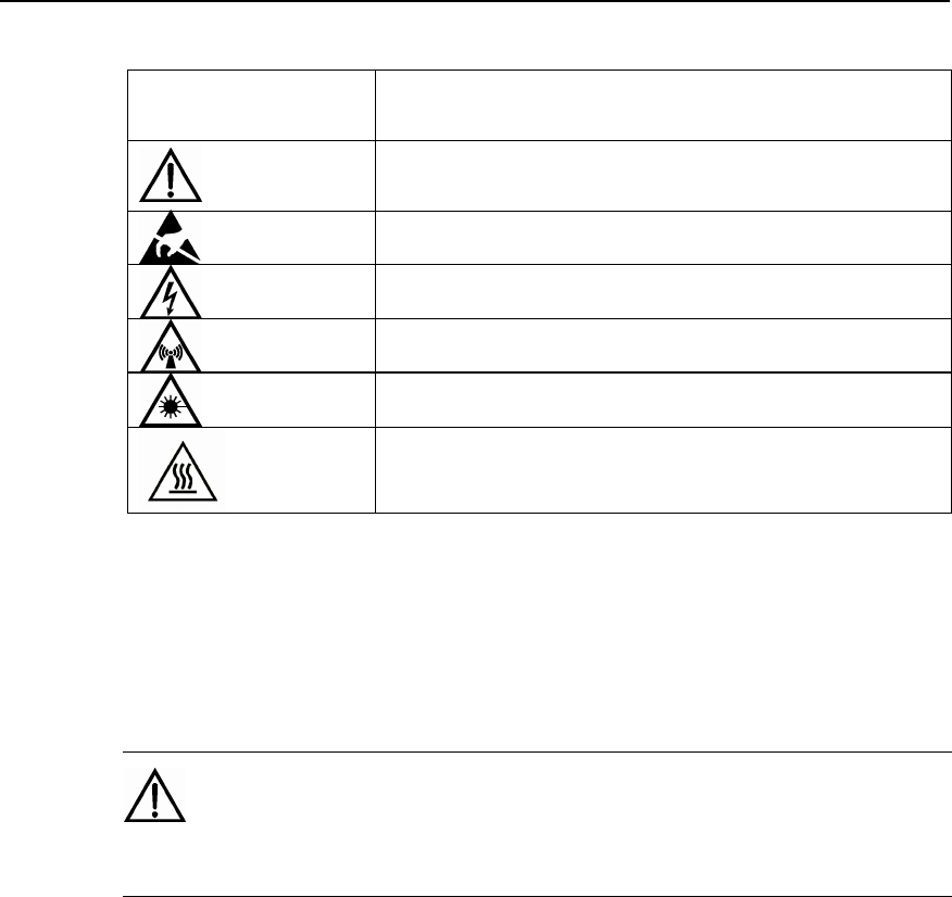
Table 1 Types and meanings of safety signs
Safety symbol Meaning
Common warning symbol: Indicates general safety precautions.
Anti-static symbol: Indicates that the equipment is sensitive to static
electricity.
Live-line symbol: Indicates dangerous voltage.
Microwave symbol: Indicates powerful electromagnetic field.
Laser symbol: Indicates powerful laser beam.
Scald symbol: Indicates that the equipment surface with high temperature,
which might cause scald or burns on the personnel. Upon this warning,
people should not touch the surface, so as to avoid any scald or burn.
2 Toxic Articles
2.1 Beryllium Oxide
Warning:
Some equipment components carrying toxic beryllium oxide are chosen unavoidably.
l Only when the components carrying beryllium oxide are damaged may the
beryllium oxide do harm to human body. The personnel who contact or handle
the components should be aware of the component peculiarity and take
corresponding preventive measures beforehand.
l To dispose of the component, the personnel should make necessary chemical
treatment or special waste processing for the component carrying beryllium in
accordance with related local regulations. The components carrying beryllium
should not be discarded freely.
Installation Manual
iSiteC ODU3601C CDMA Soft Base Station Safety Precautions
S-4
2.2 Hydrochloride
Warning:
Some components of the equipment carrying hydrochloride are used as it is unavoidable. Toxic gases
will be generated by these components when burned.
l Toxic gases will be generated when burning these components. Preventive
measures should be taken beforehand so that the components will not get
burned, and even if the burning occurs, the toxic gases will not be inhaled into
human body. The components should not be discarded freely. To dispose of the
component, the personnel should make necessary chemical treatment or special
waste processing for the component carrying hydrochloride in accordance with
related local regulations.
2.3 Hydrofluoride
Warning:
Some equipment components carrying hydrofluoride are chosen unavoidably. Toxic gases will be
generated when burning these components.
l Preventive measures should be taken beforehand so that the components will
not get burned, and even if the burning occurs, the toxic gases will not be
inhaled into human body. The components should not be discarded freely. To
dispose of the component, the personnel should make necessary chemical
treatment or special waste processing for the component carrying hydrofluoride
in accordance with related local regulations.
3 Electrical Safety
3.1 High Voltage
Danger:
High voltage power supply provides electricity for equipment operation. Direct contact or indirect contact
via damp objects and conductors with high-voltage wires or mains supply may be fatal.
Installation Manual
iSiteC ODU3601C CDMA Soft Base Station Safety Precautions
S-5
l Installation of AC power supply equipment must be implemented in compliance
with local safety regulations, and the personnel engaged in AC power supply
must be qualified for high-voltage and AC operations.
l Electrical conductors such as watches, bracelets and rings must be removed
before operation.
l If the cabinet is found to be wet, please turn off power supply immediately.
l Keep the equipment dry upon operation under humid environment.
Warning:
Improper high-voltage operations may result in fire accidents and electric shocks. Therefore, AC power
cables must be laid in compliance with local codes and regulations. High-voltage operators should be
trained and qualified.
3.2 Power Cables
Caution:
Live installation and removal of power cables are prohibited. Electric sparks or arcs may be generated
when power cables get in touch with conductors, which may cause fire accidents or eye injuries.
l Power must be switched off before installation and removal of the power cable.
l Before connecting a cable, make sure that the cable and cable label to be used
should match actual installation requirements.
3.3 Tools
Warning:
High-voltage and AC operations require special tools instead of general-purpose or makeshift tools.
Installation Manual
iSiteC ODU3601C CDMA Soft Base Station Safety Precautions
S-6
3.4 Drilling
Warning:
Unauthorized drilling on the cabinet is strictly prohibited. Improper drilling may damage the connections
and cables inside the cabinet and the metal filings produced during the drilling may cause short-circuits
of the circuit boards if they fall into the cabinet.
l Wear protective insulation gloves and remove the cables inside the cabinet
before drilling holes on the cabinet.
l Take care of your eyes when drilling holes. As the splashing metal burrs &scraps
may hurt your eyes.
l Prevent metal scraps from entering the cabinet inside.
l Improper drilling will damage the electromagnetic shielding performance of the
cabinet.
l Clean up the metal scraps after drilling.
3.5 Thunderstorms
Danger:
High-voltage and AC operations and operations on the steel towers and masts are strictly prohibited in a
stormy weather.
l Thunderstorms can generate powerful electromagnetic field in the atmosphere.
Therefore, equipment should be grounded properly in order to prevent the
equipment from being thunderstruck.
3.6 Static Electricity
Caution:
Static electricity generated by the human body may damage the electrostatic-sensitive parts on the
circuit boards, such as large-scale integrated circuit (IC).
l The grating generated between human activities and the components is the
rootage for electrostatic charge accumulation. In dry climate, the electrostatic

Installation Manual
iSiteC ODU3601C CDMA Soft Base Station Safety Precautions
S-7
charge carried by human body may go up to 30 kV, which will remain on the
human body for a rather long period of time. The operator’s contact with the
sensitive component and the resultant electric discharge will cause damage to
the component.
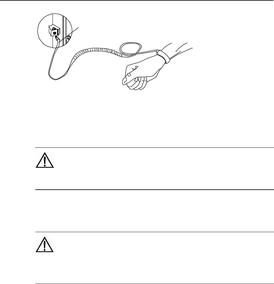
l Before contacting/touching any equipment such as holding plug-in boards, circuit
boards and IC chips, put on the anti-static wrist strap with one end well grounded
so as to prevent sensitive parts from getting damaged by static electricity on the
human body.
l Before operators touch the board or module, they should release the
electrostatic charge in their body. That is, before the operator touches a board or
a module, he or she must wear the anti-static grounded wrist strap. The
connecting line between the wrist and the grounding point should connect in
series with a resistance greater than 1 M¦¸ to protect people from being
accidentally shocked. The resistance value greater than 1 M, is rather low in
terms of electrostatic voltage discharging. The anti-static wrist strap should be
checked regularly. Using other cable to replace the cable of anti-static wrist strap
is strictly prohibited.
l Electrostatic-sensitive board or module should not be in contact with the object
with static electricity or the object that may easily generate static electricity. For
instance, packaging bags, delivery boxes and conveyor belts made of insulating
materials will generate static electricity by themselves, and can cause
electrostatic charging when in contact with human body or the earth and might
thus bring forth damages.
l Electrostatic-sensitive boards or modules can only contact quality discharging
materials, such as anti-static packing bags. The board in stock or in the course
of transportation should be packaged with anti-static packing bag.
l Before the measurement device is connected to boards or modules, first
discharge its static electricity, that is, the measurement device should be
grounded first.
l The single board or module should not be placed near strong DC magnetic field,
for instance, near the cathode ray tube of the oscilloscope. The safety distance
should be at least 10 cm.
l Damage caused by static electricity is accumulative. If the damage is slight, the
component will not malfunction. However, as the number of damages increase,
the components may suddenly fail. The electrostatic discharging damage to the
component is of two types: obvious damage and hidden damage. Hidden
damage is not shown when the damage occurs, whereas the component may
become vulnerable and easily get damaged under the condition of over-voltage
and of high-temperature.
The correct way of wearing anti-static wrist strap is shown in Figure 1.
Installation Manual
iSiteC ODU3601C CDMA Soft Base Station Safety Precautions
S-8
Plug of anti-static wrist strap
Figure 1 Wearing the anti-static wrist strap
3.7 Power Labels
Caution:
Before connecting the cables, check the correctness of labels and then make the connection.
3.8 Leakage Current
Warning:
To avoid the occurrence of large leakage current, the equipment must be grounded before connecting to
the power supply.
l Before connecting the AC input power supply, the operation and maintenance
personnel should first connect the protection-grounding terminal of the
equipment housing to the earth. The purpose of doing so is to avoid electric
shock on human body resulting from leakage current, which is usually caused by
the earth capacitance of the EMI wave filter at the AC power supply input
terminal of the equipment or the Y capacitance of the primary power supply.
Installation Manual
iSiteC ODU3601C CDMA Soft Base Station Safety Precautions
S-9
3.9 Flammable Air Environment
Danger:
The equipment should not be placed in an environment where flammable, explosive air or smog exists.
No operation should be performed under such an environment.
l The operation on any electronic equipment under such an environment will pose
absolute threat to the equipment & the operating personnel.
4 Batteries
4.1 General Operations
Danger:
Before undertaking the battery operations, the personnel should carefully read the safety precautions for
handling batteries and the correct connection of batteries.
l Improper operation of batteries will be dangerous. Guard against short-circuits of
batteries or electrolyte spillover in operation, which may pose a potential threat
to equipment, corrode metal articles and circuit boards, damage equipment and
result in short circuit of circuit board.
l Before installation and maintenance of batteries, take the following measures to
ensure safety:
l The batteries should be handled with care. Avoid strenuous vibration when
handling them.
l Metal articles such as watches, bracelets and rings must be removed.
l Use special insulated tools.
l Wear eye protection gears and take preventive measures.
l Wear rubber gloves and apron in case of electrolyte spillover.
l Hold the positive pole of batteries upright during handling. Do not handle them
upside down or in slant position.
Installation Manual
iSiteC ODU3601C CDMA Soft Base Station Safety Precautions
S-10
4.2 Short Circuit
Caution:
Short-circuit of the battery will cause personal injury. Although the voltage of ordinary battery is not high,
the powerful instantaneous current generated by short-circuit may release immense energy.
l Prevent short-circuits of batteries caused by metal articles, such as short-circuit
caused by improper use of tools. If allowed, first disconnect the batteries and
then proceed with other operations.
4.3 Harmful Gases
Caution:
Unsealed lead acid batteries should not be used, as the gas released from the batteries may cause fires
or equipment corrosion. Batteries should be fixed horizontally.
l Batteries may release inflammable gases in operation, so the place where the
batteries are placed should be well ventilated and fire prevention measures
should be taken.
4.4 High Temperature
Caution:
Excessively high temperature of batteries will cause deformation and damage to batteries and spillover
of acid liquid.
l When the temperature of battery is over 600C, check and see whether there is
spillover of acid liquid.
l In case of acid liquid spillover, please make proper and timely treatment of acid
spillover.
Installation Manual
iSiteC ODU3601C CDMA Soft Base Station Safety Precautions
S-11
4.5 Acid Liquid
Caution:
In case of acid liquid spillover, make sure that the spillovers are absorbed and neutralized.
l To move leaking batteries, bear in mind the possible damages that may be
caused by the acid liquid. Once acid liquid is found to have spilt over, absorb and
neutralize it with the following materials.
Bicarbonate: NaHCO3
Barilla: Na2CO3
Soda: Na2CO3$10H2O
l Consult the battery manufacturers as regards materials used to absorb and
neutralize acid liquid.
4.6 Battery Replacement
Warning:
Operation and maintenance personnel should not replace the batteries of specified model with that of
other model. Otherwise, possible explosion may incur.
5 Microwave and Magnetic Field
5.1 Introduction
The equipment antenna in service will generate electromagnetic radiation. Standing
too close to the antenna violates the safety codes. The equipment can only be
installed and maintained by trained professional personnel. The radiation design of
the equipment should meet the IEEE C95.1-1991 recommendation. When working
near the full-power transmitting antenna, one should first read the following safety
working requirements.
Installation Manual
iSiteC ODU3601C CDMA Soft Base Station Safety Precautions
S-12
5.2 Definition of the Environment
The uppermost level limit of the environment that can be exposed to radio magnetic
radiation is of two kinds: one is "controlled environment" and the other is
"uncontrolled environment " with less radiation.
l Controlled Environment
Controlled environment refers to a certain location where the personnel who enter the
area are aware of the potential threat of exposing themselves to the radio frequency
radiation environment. Generally, the personnel enter such areas for the profession
requirements and they get acquainted with this danger or they just pass by the areas
where possible radiation exists. The magnetic field level of the area is higher than
that of "uncontrolled environment" but no greater than that of "controlled environment"
listed in the table.
l Uncontrolled Environment
"Uncontrolled environment" refers to a certain location where the personnel who enter
the area are not aware of the potential threat of exposing themselves to the radio
frequency radiation environment, and they cannot control the environment where they
are situated. This location may include living environment or working environment.
The magnetic field level of the location cannot be greater than the uppermost level
under the "uncontrolled environment" listed in the table.
5.3 Operation Codes
Warning:
When operating on the high intensity radio frequency signal equipment, bear in mind that the
high-intensity microwave is detrimental to human health.
6 Laser
Warning:
Laser beams inside optical fibers may do harm to your eyes.
l During the installation and maintenance of optical fibers, keep eyes away from,
or avoid direct look at the optical fiber or optical transceiver outlet.
Installation Manual
iSiteC ODU3601C CDMA Soft Base Station Safety Precautions
S-13
7 High Temperature
Warning:
It is unavoidable that the temperatures of some equipment parts are rather high. Please do not touch the
surface as you wish, else scalding may occur.
l When the equipment is running in the tropical environment, the temperature
benchmark of the parts is 450C and the maximum range of temperature rise
allowed is 300C under normal working conditions. When fault occurs, the
maximum temperature rise allowed is 550C. So when the parts work at the high
temperature of 450C under normal working conditions, their highest temperature
should not exceed 750C, and when fault occurs, the highest temperature should
not exceed 1000C.
8 Fans
Warning:
To dismount the fan which is running, never dip the finger or tool into the fan that is running before the
fan is powered off or stops running to avoid damage to the equipment or injuries to human body.
l Dipping the finger into the fan while it is running may cause injuries.
l When replacing related parts, place the objects such as the parts, screws, and
tools properly. Make sure that they would not fall into the running fan, otherwise
they will damage the fan or the related equipment.
l When replacing the peripheral equipment of the fan, never dip the finger or
board into the fan to avoid any possible injuries to the equipment or the hands.
Warning:
Keep your hands and body away from the dangerous running parts to avoid possible injuries.
Installation Manual
iSiteC ODU3601C CDMA Soft Base Station Safety Precautions
S-14
9 Working at High Altitudes
9.1 General Operations
Warning:
When working at heights, beware of falling objects.
Working at heights must be in accordance with the related national regulations:
l Personnel working at heights must have undergone appropriate training.
l Take care of the mechanical devices and tools and prevent them from falling
down.
l Follow safety precautions and wear helmet and safety belt.
l Put on cold-proof clothes before working at heights in cold areas.
l Check and approve all the lifting devices before working at heights.
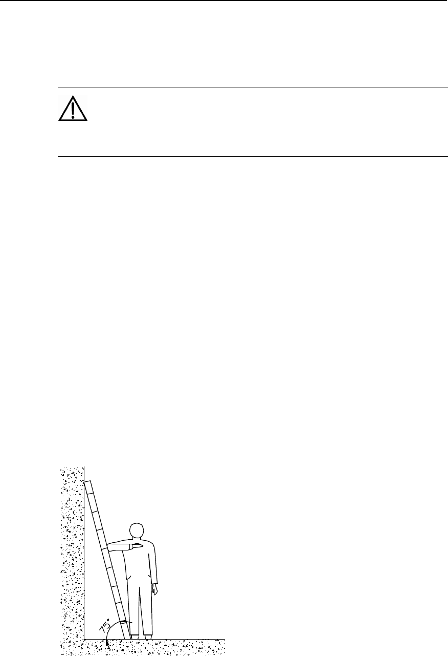
9.2 Safety Codes for Using Ladders
l Before using the ladder, first check and see whether the ladder is damaged.
Make sure the ladder is safe for use. Overload on the ladder is strictly prohibited.
l When operating under the conditions that the leaning distance of the ladder is
over 5measurement, and that of the erected ladder with two-foot is over 3meters,
and other dangerous environment, the ladder should be held by somebody or
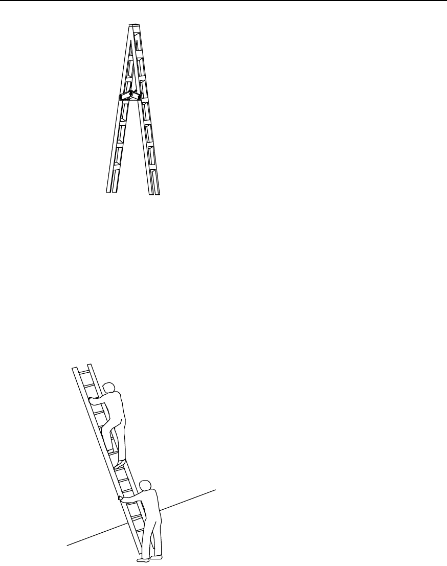
relevant safe measures should be effected. The A-shaped ladder should be
completely stretched for using, as shown in Figure 2 below.
Figure 2 The angle at which the ladder should be leaned
Installation Manual
iSiteC ODU3601C CDMA Soft Base Station Safety Precautions
S-15
Figure 3 Stretching the A-shaped ladder
l It is recommended that the slope of the ladder be 750. The slope can be
measured with angle square or with arm, as shown in the Figure 3. When using
the ladder, the wider end of the ladder should be placed against the ground or
protective measures should be taken at the bottom of the ladder for the purpose
of skid resistance. Place the ladder against a stable ground and do not place the
ladder against those objects that are easy to lean and slide themselves such as
paper box, stone and so on.
Figure 4 Climbing and using the long ladder in a safe way
Installation Manual
iSiteC ODU3601C CDMA Soft Base Station Safety Precautions
S-16
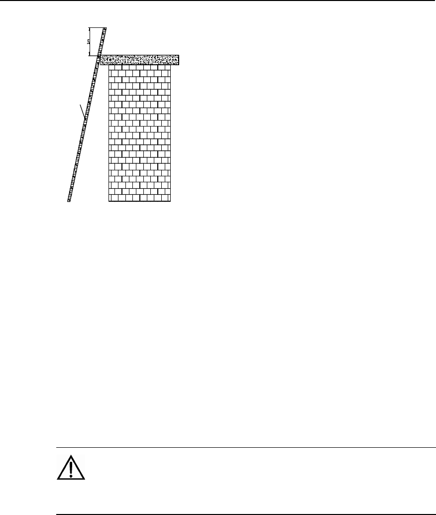
Ladder
Figure 5 Placing the ladder with the top 1 meter higher above the edge of the roof-top
l When climbing the ladder, one’s center of gravity should not deviate from the
ladder edge. To avoid danger and ensure safety, make sure that three parts of
the body should be kept on the ladder, that is, the feet should be pressed against
the ladder and one hand fast grips the ladder, as shown in Figure 4. Never climb
the topmost four rungs of a ladder. If one is about to climb to the roof, the length
of the ladder should be at least 1 meter higher above the eave, as shown in
Figure 5.
10 Other Items
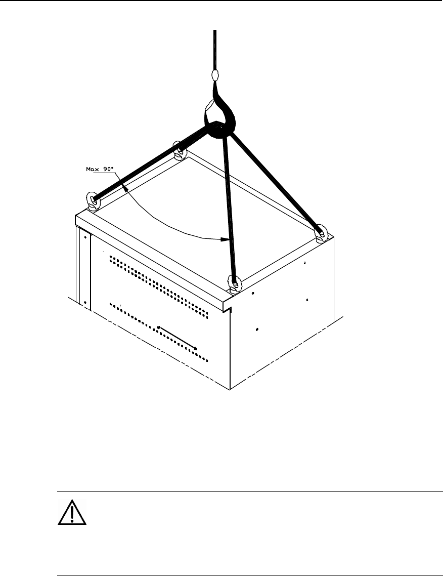
10.1 Hoisting of Heavy Objects
Warning:
Walking under the gib arm or hoisted objects are strictly prohibited when hoisting heavy objects.
l Lifting operators should undergo related training and be qualified. The lifting
devices should be checked and must be intact. Make sure that only when the
lifting devices are firmly fixed onto the weight-bearing object or onto the main
wall may lifting operations be undertaken. Use concise command to avoid wrong
operations.
l The angle between the straps at the point where they are attached to the lifting
hook should not be greater than 900 to prevent them from getting broken, as
shown in Figure 6.
Installation Manual
iSiteC ODU3601C CDMA Soft Base Station Safety Precautions
S-17
Figure 6 Hoisting of the heavy objects
10.2 Handling of Heavy Objects
Caution:
When carrying heavy object such as the cabinets, please get everything well prepared for bearing to
avoid bruises and wounds by the heavy object.
l The installation and maintenance of BSC cabinet should be done by 2 to 3
persons at best. The operations of leaning, tilting, and erecting the cabinet
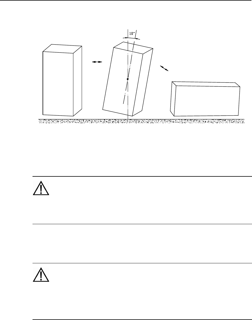
should also be undertaken with the cooperation of 2 to 3 persons. Note that the
cabinet may fall down on account of the center of gravity when the tilt angle of
the center of gravity exceeds 10 degrees.
Installation Manual
iSiteC ODU3601C CDMA Soft Base Station Safety Precautions
S-18
The process of laying down and erecting a cabinet is shown as Figure 7.
Figure 7 The process of laying down and erecting a cabinet
10.3 Sharp Edges
Warning:
When conveying equipment by hand, please wear protective gloves to prevent cuts and injuries caused
by sharp edges.
10.4 Inserting & Drawing Out the Boards
Caution:
Do not apply too much force when inserting the boards to avoid bending of the pins on the backplane.
Insert the board along the slot to avoid short-circuit resulting from their surfaces contacting each other.
Keep hands off the board circuit, elements, connectors or wiring trough when holding a board by hand.
Installation Manual
iSiteC ODU3601C CDMA Soft Base Station Safety Precautions
S-19
10.5 Bundling the Signal Cables
Caution:
Signal cables should be tied separately from strong current or high voltage cables, and the spacing
between adjacent cable ties should be at least 150mm.
10.6 Maintenance and Commissioning by a Single Person is not Allowed
Caution:
One should not attempt to perform the maintenance or commissioning in the areas of the equipment
interior unless another qualified professional who can give instructions and is capable of self-saving is
present.

Installation Manual
iSiteC ODU3601C CDMA Soft Base Station Table of Contents
i
Table of Contents
Chapter 1 Installation Preparations ......................................................................................1-1
1.1 Personnel Requirements ............................................................................................1-1
1.1.1 Basic Requirements.........................................................................................1-1
1.1.2 Requirements for Antenna & Feeder Installation Personnel.................................1-1
1.2 Technical Documents Preparation ..............................................................................1-2
1.3 Installation Tools & Instruments Preparation ................................................................1-3
1.4 Installation Environment Check...................................................................................1-6
1.5 Project Plan and Kickoff Coordination .........................................................................1-6
1.5.1 Project Plan .....................................................................................................1-6
1.5.2 Kickoff Coordination .........................................................................................1-7
1.6 Unpacking Check.......................................................................................................1-7
1.6.1 Packing List Collation .......................................................................................1-7
1.6.2 Unpacking Inspection on Wooden Cases...........................................................1-8
1.6.3 Unpacking Inspection on Cartons......................................................................1-9
1.6.4 Acceptance and Handover..............................................................................1-11
Chapter 2 Installing Cabinet Hardware.................................................................................2-1
2.1 Hardware Components ..............................................................................................2-1
2.1.1 Component Structure .......................................................................................2-1
2.1.2 Introduction of Hardware Major Equipment ........................................................2-2
2.1.3 Introduction of Hardware Auxiliary Equipment....................................................2-2
2.1.4 Installation Mode..............................................................................................2-3
2.1.5 Installation Flow...............................................................................................2-3
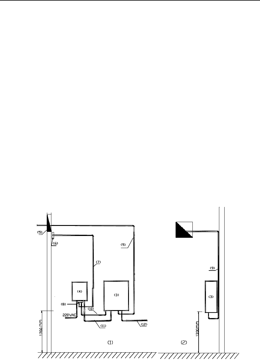
2.2 Installation Planning...................................................................................................2-5
2.2.1 Example of Indoor Wall Installation....................................................................2-5
2.2.2 Example of Indoor Plinth Installation..................................................................2-6
2.2.3 Example of Concrete Pole Installation ...............................................................2-6
2.2.4 Example of Metal Mast Installation on Building-top .............................................2-9
2.2.5 Example of Tower Installation .........................................................................2-11
2.3 Installing Major Equipment .......................................................................................2-14
2.3.1 Installation Flow.............................................................................................2-14
2.3.2 Installing ODU3601C on the Wall ....................................................................2-15
2.3.3 Installing ODU3601C on Plinth........................................................................2-19
2.3.4 Installing ODU3601C on Metal Mast and Concrete Pole ...................................2-21
2.3.5 Installing Modules ..........................................................................................2-23
2.3.6 Installing Cables ............................................................................................2-25
2.3.7 Installing Shell ...............................................................................................2-30
2.3.8 Installing Sun-shading Cover ..........................................................................2-31

Installation Manual
iSiteC ODU3601C CDMA Soft Base Station Table of Contents
ii
2.4 Installing Auxiliary Equipment ...................................................................................2-31
2.4.1 Installing IAFB ...............................................................................................2-31
2.4.2 Installing AC Lightning Protection Box.............................................................2-33
2.4.3 Installing UPS ................................................................................................2-39
2.4.4 Installing IABB ...............................................................................................2-39
2.5 Installing Cables ......................................................................................................2-47
2.5.1 Cable Connection Requirements.....................................................................2-48
2.5.2 Networking of AC Lightning Protection Box......................................................2-50
2.5.3 Networking of IAFB ........................................................................................2-53
2.5.4 Networking of Inverter ....................................................................................2-64
Chapter 3 Installing RF Antenna and Feeder System ...........................................................3-1
3.1 Installation Flow.........................................................................................................3-1
3.2 Installing Antenna Accessories ...................................................................................3-3
3.2.1 Installing Omni Antenna Accessories.................................................................3-3
3.2.2 Installing Directional Antenna Accessories.........................................................3-4
3.3 Installing Grounding Bar .............................................................................................3-6
3.4 Installing Antenna Support..........................................................................................3-8
3.4.1 Installing Support on Tower Platform.................................................................3-8
3.5 Installing Antenna ....................................................................................................3-16
3.5.1 Antenna Facade ............................................................................................3-16
3.5.2 Hoisting Antenna ...........................................................................................3-16
3.5.3 Installing Omni Antenna .................................................................................3-16
3.5.4 Installing Directional Antenna..........................................................................3-19
3.6 Installing Feeder Window .........................................................................................3-23
3.6.1 About Feeder Window....................................................................................3-23
3.6.2 Installing Feeder Window ...............................................................................3-24
3.7 Installing Feeders ....................................................................................................3-25
3.7.1 Cutting Feeder ...............................................................................................3-25
3.7.2 Hoisting Feeder .............................................................................................3-26
3.7.3 Routing Feeder ..............................................................................................3-27
3.7.4 Affixing Feeder Labels....................................................................................3-28
3.7.5 Grounding Feeders ........................................................................................3-28
3.7.6 Leading Feeder into Equipment Room.............................................................3-30
3.7.7 Connecting Feeder and ODU3601C................................................................3-31
3.8 System Testing........................................................................................................3-32
Chapter 4 Installation Check ................................................................................................4-1
4.1 Overall Check............................................................................................................4-1
4.1.1 Checking Equipment Installation .......................................................................4-1
4.1.2 Checking Cable Connection..............................................................................4-1
4.1.3 Checking Lightning Protection Grounding ..........................................................4-1
4.2 Power-on Check........................................................................................................4-3
4.3 Checking Environment Condition ................................................................................4-3

Installation Manual
iSiteC ODU3601C CDMA Soft Base Station Table of Contents
iii
Chapter 5 Software Installation and System Commissioning...............................................5-1
5.1 Software Installation...................................................................................................5-1
5.2 System Commissioning..............................................................................................5-1
5.2.1 Test Equipment................................................................................................5-1
5.2.2 Service Flow Overview.....................................................................................5-1
5.2.3 Test of Location Update Flow............................................................................5-2
5.2.4 Test of MOC Flow............................................................................................5-2
5.2.5 Test of MTC Flow.............................................................................................5-3
5.2.6 Test of Handoff Flow........................................................................................5-3
5.2.7 Test of Mobile Originated SMS Flow..................................................................5-4
5.2.8 Test of Mobile Terminated SMS Flow................................................................5-5
5.2.9 Test of Mobile Originated Packet Data Flow.......................................................5-5
5.2.10 Test of MS Packet Data Flow (Downlink Service Rate) .....................................5-6
5.2.11 Processing of Abnormalities in the Test ...........................................................5-7
Appendix A Installing IAFB ................................................................................................. A-1
A.1 Installation Flow ....................................................................................................... A-1
A.2 Wall Installation ........................................................................................................ A-1
A.3 Metal Mast Installation .............................................................................................. A-4
A.4 Pole Installation........................................................................................................ A-5
A.5 Installation Check..................................................................................................... A-6
Appendix B Requirements for Antenna Isolation ................................................................B-1
Appendix C Making Connectors..........................................................................................C-1
C.1 Overview.................................................................................................................C-1
C.2 Making 7/16 DIN Connector and N Connector for Jumper ...........................................C-1
C.3 Making 7/16 DIN Connector and N Connector for 7/8 Feeder ......................................C-5
Appendix D Preparing Grounding Clips ..............................................................................D-1
D.1 Overview.................................................................................................................D-1
D.2 Preparation Process.................................................................................................D-1
Appendix E Engineering Labels for Cables ......................................................................... E-1
E.1 Introduction to Labels ............................................................................................... E-1
E.1.1 Material.......................................................................................................... E-1
E.1.2 Type and Shape ............................................................................................. E-1
E.1.3 Printing Labels ............................................................................................... E-3
E.1.4 Writing Labels ................................................................................................ E-5
E.1.5 Affixing Labels................................................................................................ E-6
E.1.6 Information Carried on Labels.......................................................................... E-8
E.1.7 Remarks ........................................................................................................ E-9
E.2 Engineering Labels for Ethernet Cables ..................................................................... E-9
E.3 Engineering Labels for Optical Fibers ...................................................................... E-10
E.3.1 Labels for the Fiber that Connects Two Devices ............................................. E-11
E.3.2 Labels for the Fiber that Connects the Device and the ODF............................. E-12

Installation Manual
iSiteC ODU3601C CDMA Soft Base Station Table of Contents
iv
E.4 Engineering Labels for Trunk Cables ....................................................................... E-13
E.4.1 Labels for the Trunk Cable that Connects Two Devices................................... E-13
E.4.2 Labels for the Trunk Cable that Connects the Device and the DDF .................. E-14
E.5 Engineering Labels for Power Cables ...................................................................... E-15
E.5.1 Labels for DC Power Cables ......................................................................... E-15
E.5.2 Labels for AC Power Cables.......................................................................... E-17
Appendix F Engineering Labels of the Feeder..................................................................... F-1
F.1 Engineering Labels of the Feeder .............................................................................. F-1
F.2 Engineering Labels of the Jumper.............................................................................. F-3

Installation Manual
iSiteC ODU3601C CDMA Soft Base Station Chapter 1 Installation Preparations
1-1
Chapter 1 Installation Preparations
1.1 Personnel Requirements
1.1.1 Basic Requirements
If the project is cooperated with other parties, engineers from cooperation parties shall
play the key role in installation, engineers from the user shall provide necessary
assistance, and the engineers from the vendor shall supervise the whole installation
process.
If the project is not cooperated with other parties, engineers from the vendor shall play
the key role in installation, and engineers from the user shall provide assistance.
Engineers from the cooperation party shall be strictly trained and examined by the
vendor. Only after they have mastered the installation and testing methods, and
obtained the qualification certificates, can they implement the installation and
commissioning under the supervision of vendor engineers.
Engineers from the user shall receive some training given by the vendor to master the
installation and construction methods prior to the installation.
1.1.2 Requirements for Antenna & Feeder Installation Personnel
The antenna & feeder system is normally installed by the antenna & feeder installation
personnel under the supervision of the project supervisor. The number of installation
personnel should be determined according to installation environment.
Project supervisor:
l Should be familiar with the materials, tools and methods involved in the antenna &
feeder installation.
l Should have a strong consciousness of safety, organize the installation personnel
and coordinate their work on the principle of "Safety First", especially for the job on
tower.
l Should fill in the engineering data faithfully, e.g., antenna pitch angle, antenna
azimuth angle and number of feeders, etc.
Personnel for installation on the tower:
l Should obtain the certificates for the relevant work through relevant training;
Installation Manual
iSiteC ODU3601C CDMA Soft Base Station Chapter 1 Installation Preparations
1-2
l Should be in good health, free of alcohol and have paid for personal safety
insurance;
l Should follow the operating requirements for safety appliances and wear safety
belts;
l Should not wear loose clothes or slipped shoes. And they must take with them
stuffs for binding up wounds.
Caution:
1) The project supervisor should contact users who will present on the site before kickoff so as to prepare
the instruments and tools needed. If the feeders are to be routed through the cabling holes between
buildings, it is necessary to remind the users of the keys to the rooms or roof corridor through which the
feeders run;
2) When multiple persons are needed to climb the tower, the person carrying the tool kit should climb up
last and down first lest a barely fallen tool should injure others.
3) The tool kit should be opened only when tools are needed and be closed immediately after getting the
tools.
4) All persons on site must wear protecting caps, and each installation team should be provided with a first
aid kit;
5) The personnel under the tower are under the obligation to keep persons not related to the project,
especially children away from the engineering site;
1.2 Technical Documents Preparation
I. Engineering design documents:
l iSiteC ODU3601C CDMA Soft Base Station Network System Network Planning
l iSiteC ODU3601C CDMA Soft Base Station Engineering Design
These documents should be prepared by the design unit appointed by the user. The
user should provide a copy of the documents to Huawei prior to the equipment delivery.
II. Installation guide documents:
l iSiteC ODU3601C CDMA Soft Base Station User Manual;
l iSiteC ODU3601C CDMA Soft Base Station Installation Manual.
The documents should be provided by Huawei in the delivery.

Installation Manual
iSiteC ODU3601C CDMA Soft Base Station Chapter 1 Installation Preparations
1-3
&
Note:
In the cooperative installation project, the project-related documents such as iSiteC ODU3601C CDMA
Soft Base Station User Manual and iSiteC ODU3601C Soft CDMA Base Station Installation Manual are to
be provided to the cooperator by Huawei prior to the project kickoff.
1.3 Installation Tools & Instruments Preparation
All the tools & instruments listed in Table 1-1 and Table 1-2should be available for the
installation.

Installation Manual
iSiteC ODU3601C CDMA Soft Base Station Chapter 1 Installation Preparations
1-4
Table 1-1 General installation tools and instruments
List of universal tools
No. Measuring and
marking tools Concrete drilling tools Fastening tools Small tools Auxiliary means List of special tools List of
instruments
1 A 50m ribbon tape A percussion drill Three Phillips screwdrivers
(respectively of 4', 6' and 8') A hacksaw (with some saw
blades) A pair of tweezers A non-conductive
screwdriver A multi meter
2 A 5m measuring
tape Some matching bits Three straight screwdrivers
(respectively of 4', 6' and 8') A tap wrench (with some M4
and M5 screw taps) A paintbrush Anti-static wrist strap A power meter
3 A 400mm level bar A cleaner Four adjustable wrenches
(respectively of 6', 8', 10' and
12')
A pair of sharp nose pliers
(8') A pair of scissors A safety knife Portable computer
4 Marking pen
A terminal block (with
three 2-phase sockets and
three 3-phase sockets,
current capacity>15A)
Combination wrenches
(respectively of 17' and 19') A pair of diagonal pliers (8') A 300W soldering iron A stripper for 75W coaxial
cables Frequency meter
5 Socket head wrench A pair of slip joint pliers (8') A 40W soldering iron A pair of connector
crimping pliers for 75W
coaxial cables
Test mobile phone
(optional)
6 A set of inner hexagon
spanners A pair of pincer pliers (8') Some tin wires A pair of multi-purpose
crimping pliers Site master
7 A set of socket wrenches A set of broach files (of
medium size) A heat blower
8 A 5kg nail hammer Electrician’s knife A solder absorber
9 Flat Phillips screwdriver (of
medium size)
A pair of hydraulic pliers
(or Hercules crimping
pliers)
10 Ladder
11 Wire nipper
12 Paper knife
13 Insulating tape

Installation Manual
iSiteC ODU3601C CDMA Soft Base Station Chapter 1 Installation Preparations
1-5
Table 1-2 Tools and instruments for antenna feeder installation
Special tools for antenna & feeder system installation
No. Measuring tools Suspension-mounting
tools Special tools for feeders Protective tools Tools borrowed from the
local user Other tools
1 An angle display An assembly pulley A feeder nipper Safety belts (for personnel required
to operate out of the tower platform) Double ladder Canvas bag for
tools
2 A compass Two ropes (1 thin and
1thick, both 150m long) Cable cutter (applicable for the feeder
specification) Protecting caps Lifting tools for the main
feeder wheel spindle Gloves
3 Feeder noose Special tools for making feeders (1/2",
7/8") Safety ropes Walkie-talkie
4 Blast lamp (used in the cold
environment to warm and soften the
waterproof & sealing materials) Thick union suits Multi-purpose
outlets
5 RF protective clothing

Installation Manual
iSiteC ODU3601C CDMA Soft Base Station Chapter 1 Installation Preparations
1-6
1.4 Installation Environment Check
During the project preparation, the office personnel shall perform "first check prior to
the installation" with survey engineers according to the engineering guidebook and
then the second check with the project supervisor and fill in the check items in
Installation Environment Checklist accordingly. The purpose is to check whether the
environment is suitable for the deployment.
1.5 Project Plan and Kickoff Coordination
1.5.1 Project Plan
After confirming the qualification of engineering environment, project supervisor should
contact the representative of the user, and draft and notify the user the initial plan list of
installation planning and progress according to the condition and preparation of the
project.
I. Project interface
In principle, Huawei's Project Recommendation and the terms and conditions related to
project interface after the negotiation between user and vendor serve as the basis of
operation. Below are the common principles:
l The user is responsible for the preparation of equipment room environment;
l The user is responsible for the coordination of the auxiliary equipment in the
equipment room;
l The project interface is based on the contract and project files and is finalized by
means of the negotiation between both parties.
II. Project coordination and cooperation
l Personnel
The project supervisor is the principal of the project. He is responsible for providing the
list of the supervisors of this project and sub-projects and the way to contact them. It is
recommended that the user provide the list and contact information of its corresponding
technicians.
l Tools
The vendor should in advance inform the user of the tools inconvenient for
transportation or tools the vendor cannot provide. And the user should provide these
tools.

Installation Manual
iSiteC ODU3601C CDMA Soft Base Station Chapter 1 Installation Preparations
1-7
III. Progress arrangement
The progress of the project should be arranged according to the preparation of the
project. A written plan should be worked out and submitted to the user for negotiation
and confirmation. The plan should include the following contents:
l Delivery time and expected arrival time;
l Date when engineers arrive the place of the user;
l Progress arrangement of project installation and commissioning.
1.5.2 Kickoff Coordination
After arriving at the place of the user, the project supervisor should call a kick off
coordination meeting with the user. In this meeting, both parties should decide their
persons in charge, and achieve an agreement on installation period, project schedule
and cooperation matters.
1.6 Unpacking Check
In the non-turnkey project, both the user and the project supervisor (engineer from
Huawei or cooperative party) are required to be present at the unpacking site. If one
party is absent at the unpacking site, another party who unpacks shall responsible for
any error occurring to the articles.
In the turnkey project, it is the project supervisor and the order management engineers,
who unpack, check & accept, hand over the articles, and make a confirmation with
signatures. The operation of Unpacking check and problem feed back in this case is
almost the same as that of the non-turn key project, except that the user does not need
to sign. The goods will be handed over to the user after passing the initial check of the
project.
The following will mainly deals with the former case.
1.6.1 Packing List Collation
Before unpacking, both parties should check if the packing cases are damaged. If so,
stop unpacking and contact the order management engineer at the local office of
Huawei, waiting for the handling. Meanwhile, check if the quantity of cases on the site
agrees with the Packing List, and if the place of delivery agrees with the actual
installation place. If there is any disagreement, the project supervisor should feed back
the Article Problem Feedback Form confirmed by the user with a signature to the order
management engineer at the local office within 3 days.
After all the above inspections are ok, unpack the cases to check and accept the
articles.
Installation Manual
iSiteC ODU3601C CDMA Soft Base Station Chapter 1 Installation Preparations
1-8
There are two kinds of packages: wooden cases and cartons. The unpacking tools
should be used accordingly.
&
Note:
The Packing List is usually in the carton with red label.
1.6.2 Unpacking Inspection on Wooden Cases
Generally, the wooden case is used to pack heavy items, such as cabinet and feeder
clips, etc.
The packing materials for the cabinet include the wooden case, foamed wrap angles
and a plastic bag, as shown in Figure 1-1. Better not unpack the package until moving it
to or near the equipment room (if enough space is available) so as to avoid damages to
the unpacked cabinet.
(8)
(1)
(2)
(3)
(4)
(5)
(6)
(7)
(3)
(4)
(3)
(7)
(4)
(1) Moisture-proof bag (2) Wooden case back (3) Foamed wrap angle
(4) Wooden case top (5) Wooden case front (6) Pressure-sensitive tap
(7) Foamed L-square (8) Packing label
Figure 1-1 Wooden case
Unpack the package as follows:
1) Pry the outer iron sheet and unpack the cover plate using the nail hammer, the
pliers, the straight screwdriver and the crowbar.
2) Insert a straight screwdriver in the skin plate seam and loosen the plate. Then
insert the crowbar to pry it off the package.
3) Erect the wooden case and take out the equipment. Do not remove the plastic bag
before the equipment is taken out.
Installation Manual
iSiteC ODU3601C CDMA Soft Base Station Chapter 1 Installation Preparations
1-9
4) Remove the plastic bag.
Inspect the cabinet for the following problems:
l Whether there is any defect on the cabinet appearance;
l Whether the whole cabinet is deformed;
l Whether the environment inside the cabinet is clean;
l Whether other goods such as the storage battery and feeder clip are all there and
intact.
Caution:
The checked goods should be organized by type.
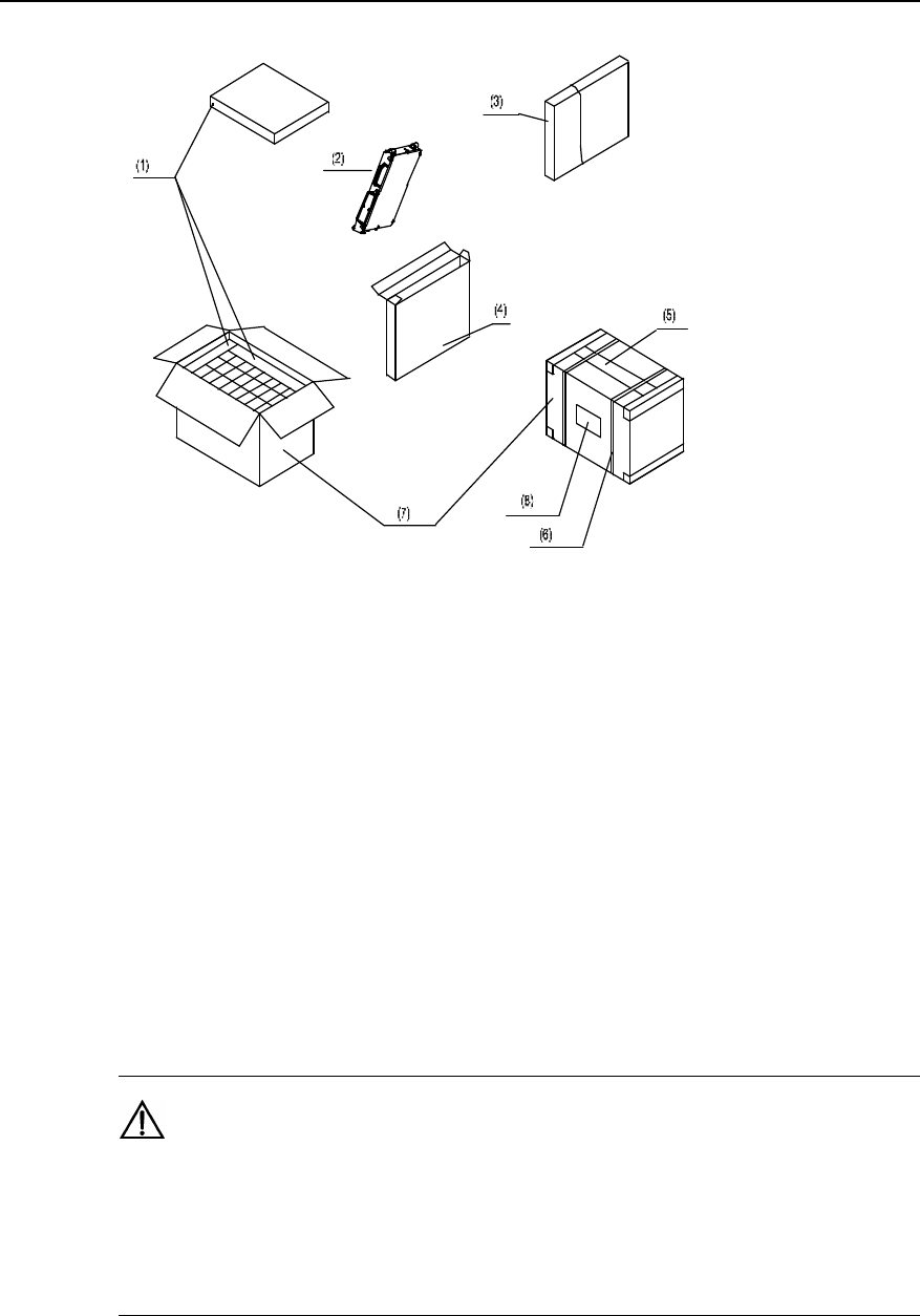
1.6.3 Unpacking Inspection on Cartons
Generally, the carton is used to pack various modules and terminal equipments, etc.
The module is placed in an antistatic bag for transportation. Inside the bag, there is a
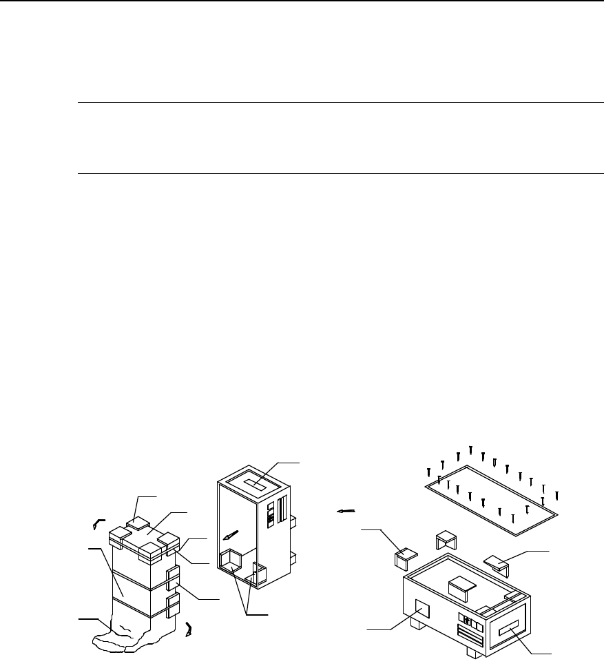
desiccant to keep it dry. The packing of a module is shown in Figure 1-2. Antistatic
measures should be taken during the unpacking so as to avoid any damage to the
equipment. Meanwhile, ensure a proper ambient temperature and humidity.
Caution:
When moving the equipment from an environment with a relatively low temperature and humidity and to
that with a relatively high temperature and humidity, unpack it until at least 30 minutes later. Otherwise, the
moisture may condense on the equipment surface and thus cause damage.
Installation Manual
iSiteC ODU3601C CDMA Soft Base Station Chapter 1 Installation Preparations
1-10
(1) Foam plate (2) Module (3) Antistatic bag (4) Board box
(5) Pressure-sensitive adhesive tape (6) Packing tape (7) Carton (8) Carton label
Figure 1-2 Unpacking of the module
Unpack the carton as follows:
1) Check the type and quantity of the modules as per the carton label;
2) Snip the packing tape using a pair of diagonal pliers;
3) Rip the adhesive tape along the joint seams using a paper knife. Be careful not to
insert the knife too deep, avoiding damage to the modules;
4) Unpack the carton and take out the foam plate;
5) Check whether the quantity marked on the label of the module box is in
compliance with that on the carton label. If yes, take out the module box;
6) Open the module box and take out the module from the antistatic bag.
Caution:
1) Anti-static measures should be taken when holding the modules;
2) When the module box is open, the module shall be seen wrapped in a packing bag and an antistatic bag.
Do not tear or discard these two bags, as they can be used to store the spare modules or to wrap the
failure modules for repair.
Installation Manual
iSiteC ODU3601C CDMA Soft Base Station Chapter 1 Installation Preparations
1-11
Check the goods after unpacking. The next unpacking cannot be done unless the
present unpacking check has been finished. Make sure that no more modules in the
cartons before opening the next. Avoid discarding the cartons before all modules have
been taken away from it. The check covers:
l Whether the internal packing has been damaged;
l Whether the number and type of the modules are in line with the Packing List;
l Whether there is any broken printed circuit modules or any components detached
from the module.
Caution:
1) For inner packing, any breakage of the inner packaging should be recorded in detail;
2) Check all the boards as per the delivery list. If any nonconformity, contact the vendor immediately.
3) The check goods should be organized by type.
1.6.4 Acceptance and Handover
After the acceptance, both parties must sign on the Packing List to confirm that there is
no problem with the articles. After that, the articles are handed over to the user.
During the inspection, if "outstanding articles" is stated in the Packing List, it is
necessary to feed it back to the order management engineer at the local office. The
order management engineer will urge the relevant department of Huawei to deliver the
outstanding articles as soon as possible and meanwhile sign on the Packing List. In the
case of shortage of articles, wrong articles, extra articles delivered or damage of
articles, both parties should sign the Unpacking Inspection Memo and Packing List.
Meanwhile, the project supervisor should fill in the Article Problem Feedback Form and
feed it back to the order management engineer at the local office within 3 days. The
project supervisor should also be responsible for well keeping the original condition of
articles with problems as well as the inner and outer packing, for future investigation
and verification.
The person assigned by the user will take charge of the articles after the acceptance
and the handover. The articles should be stored in a special room where should have
appropriate temperature and humidity, little shock, little dust, satisfactory antistatic
measures and be rodent-proof and free from any intense electromagnetic interference.
The user should bear the consequences of any damage or loss to the equipment due to
improper storage thereof.
Installation Manual
iSiteC ODU3601C CDMA Soft Base Station Chapter 2 Installing Cabinet Hardware
2-1
Chapter 2 Installing Cabinet Hardware
2.1 Hardware Components
Major equipment of ODU3601C hardware to be installed include rack, Micro-bts
AC-DC Power Supply Module (MAPM), Micro-bts Transceiver Module (MTRM) ,
Micro-bts Radio Frequency Front End Module (MFEM), Micro-bts Power Amplifier
Module (MPAM) and plastic shell. In addition, a sun-shading cover should be installed
to ensure the reliability of BTS that is installed outdoors.
Besides the above major equipment, ODU3601C also comprises auxiliary equipment
in actual installation environment, such as iSite Auxiliary Facility Box (IAFB), AC
lightning protection box, Uninterrupted Power Supply (UPS) and iSite Auxiliary Battery
Box (IABB).
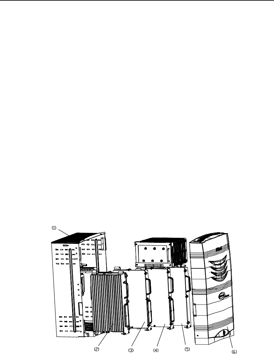
2.1.1 Component Structure
Figure 2-1 shows the major components of the ODU3601C.
1) Rack 2) MAPM 3) MTRM
4) MFEM 5) MPAM 6) Plastic shell
Figure 2-1 ODU3601C structure

Installation Manual
iSiteC ODU3601C CDMA Soft Base Station Chapter 2 Installing Cabinet Hardware
2-2
2.1.2 Introduction of Hardware Major Equipment
I. Rack
Rack is composed of backplane box, module guide rail, and back shell to bear various
modules.
Backplane box has been fixed on the back shell before delivery. Modules are
connected to the backplane box via connectors, on which waterproof measures have
been taken.
Module guide rail is also fixed on the back shell, along which modules like MAPM,
MTRM, MFEM, and MPAM are installed from left to right in their corresponding slots.
Back shell can be installed via installation accessories on walls, standing supports,
concrete poles, metal masts, towers, etc. That is, there are multiple choices when
determining the ODU3601C site.
II. Modules
Modules are the core of ODU3601C, including MAPM, MTRM, MFEM and MPAM.
Each module is sealed for waterproof, and bottom leading-out mode is adopted for their
corresponding cables.
MPAM has been installed with heat-pipe radiator before delivery, so be carefule not to
damage the heat pipe during installation.
III. Plastic shell
Plastic shell is buckled on the rack and then fixed and locked after the cable distribution.
So the installation of major equipment of ODU3601C is completed.
2.1.3 Introduction of Hardware Auxiliary Equipment
Auxiliary equipment of ODU3601C includes IAFB, AC lightning protection box, UPS,
and IABB. All auxiliary equipment can work outdoors and is optional according to actual
installation environment and project requirements.
I. IAFB
IAFB can provide certain assistance for ODU3601C, i.e. it can hold the major auxiliary
equipment of ODU3601C so as to realize the integrated outdoor installation of auxiliary
equipment of the ODU3601C.

Installation Manual
iSiteC ODU3601C CDMA Soft Base Station Chapter 2 Installing Cabinet Hardware
2-3
II. AC lightning protection box
The box helps to realize the ligtning protection for the AC input power of ODU3601C. In
terms of varied discharging currents of the box, it can be classfied into three types 20kA,
40kA and 100kA. In this manual, all AC lightning protection boxes are of 20kA type.
III. UPS
It is recommended to adopt no-wind UPS with the battery voltage 72V. The packing of
UPS is sunshine-proof, waterproof and moistureproof, so the UPS can operate in
outdoor environment.
IV. IABB
The backup power battery groups of ODU3601C can be placed in the IABB safely
satisfying the backup power supply requirement of the ODU3601C. The box structure
is similar to that of IAFB.
2.1.4 Installation Mode
In terms of environment, the ODU3601C can be installed in the following modes:
l Indoor installation
l Outdoor installation
In terms of conditions, the ODU3601C can be installed in the following modes:
l Wall installation (Installing ODU3601C on wall)
l Plinth installation (Installing ODU3601C on plinth)
l Pole installation (Installing ODU3601C on pole)
l Metal mast installation (Installing ODU3601C on metal mast)
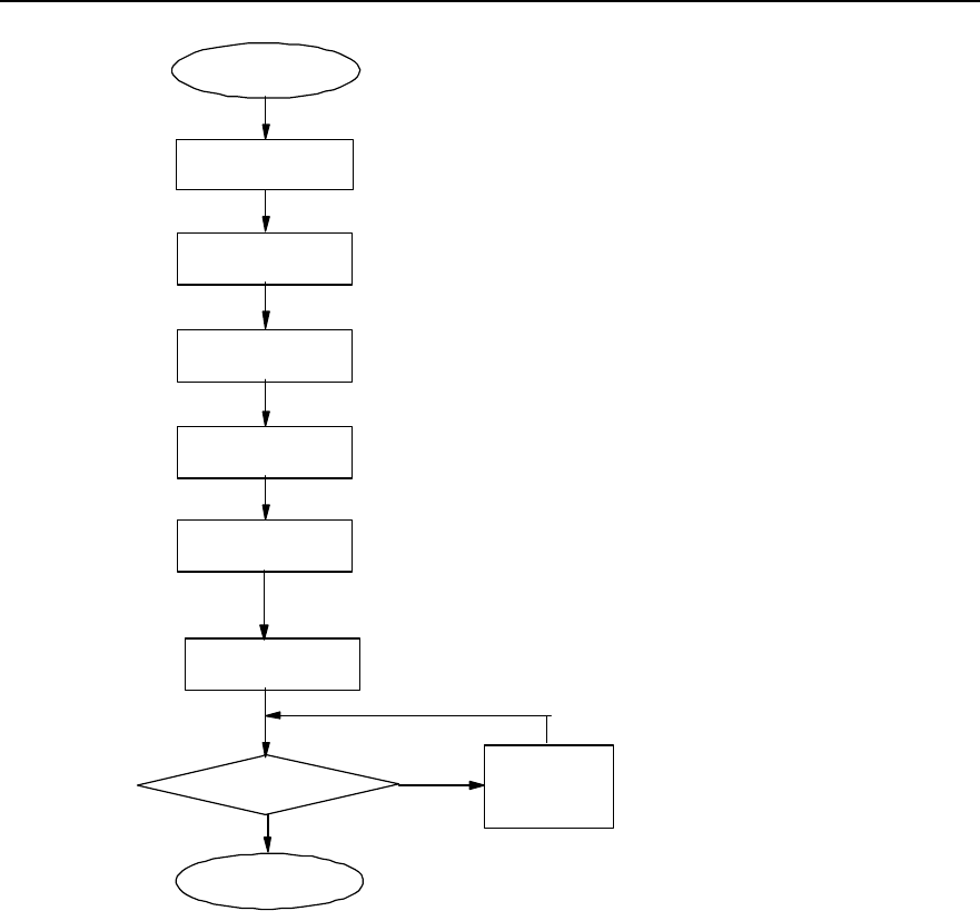
2.1.5 Installation Flow
Installation flow is almost the same no matter which mode is adopted.
Figure 2-2 shows the installation flow of ODU3601C hardware system.
Installation Manual
iSiteC ODU3601C CDMA Soft Base Station Chapter 2 Installing Cabinet Hardware
2-4
Start
Install major
equipment
Plan
Install auxiliary
equipment
Hardware installation check OK?
End
Reinstall the
relevant part
N
Y
Install antenna and feeder
system
Install cables
Install GPS antenna and
feeder system
Figure 2-2 Hardware installation flow
I. Description
1) Planning
You can start to install the ODU3601C only after plans have been made for the
installation positions and cable distribution of all equipment, and relevant support
equipment like supports and masts have been prepared.
2) Installing major equipment
ODU3601C major equipment refers to the hardware equipment that accomplishes the
major functions of the ODU3601C.
3) Installing auxiliary equipment
ODU3601C auxiliary equipment refers to the equipment that provides power and
functions like lightning protection and transmission for the major equipment of the
ODU3601C.
Installation Manual
iSiteC ODU3601C CDMA Soft Base Station Chapter 2 Installing Cabinet Hardware
2-5
4) Installing cables
Connect cables among all above equipment after their installation. Cables include
transmission cables, power cables and grounding cables.
5) Installing antenna and feeder system
Installing antenna and feeder system is to install antennae, prepare connectors, etc.
6) Installing GPS antenna and feeder system
Installing GPS antenna and feeder system is to install GPS receive antenna and
lightning arrester, prepare connectors, etc.
7) Checking hardware installation
Check the installation quality and accept the installation of ODU3601C hardware upon
completion.
2.2 Installation Planning
Following are several typical installation layout examples for reference.
2.2.1 Example of Indoor Wall Installation
Figure 2-3 shows the indoor wall installation of ODU3601C with IAFB.
1) Front view 2) Side view 3) ODU3601C
4) IAFB 5) Feeder window 6) Indoor grounding bar
7) Protection Ground (PGND) bus 8) IAFB grounding bar 山 9) Jumper
10) ODU3601C PGND cable 11) Power cable 12) Fiber
Figure 2-3 Installing ODU3601C on the wall
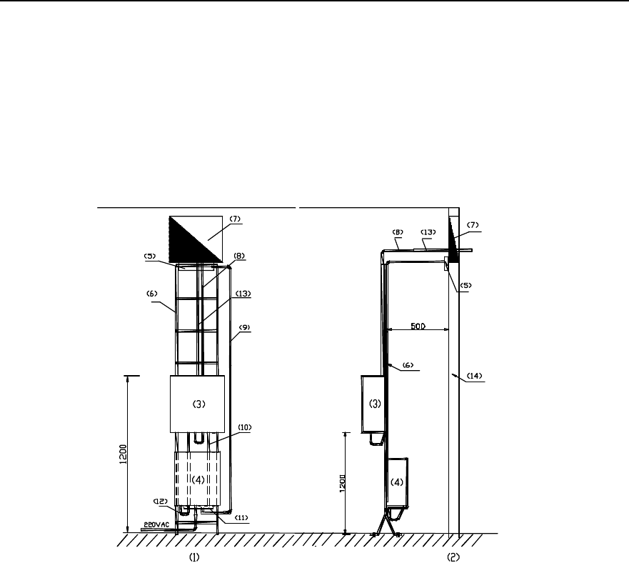
Installation Manual
iSiteC ODU3601C CDMA Soft Base Station Chapter 2 Installing Cabinet Hardware
2-6
2.2.2 Example of Indoor Plinth Installation
Inside the equipment room, if ODU3601C cannot be installed on the wall (e.g. structure
pole, hollow wall body, clapboard wall in the simplified equipment room), it can be
installed on the plinth. The position of the plinth should be as close to the wall as
possible.
Figure 2-4 shows the indoor plinth installation of ODU3601C with IAFB.
1) Front view 2) Side view 3) ODU3601C
4) IAFB 5) Indoor grounding bar 6) Support
7) Feeder window 8) Jumper 9) Protection grounding
10) ODU3601C PGND cable 11) IAFB grounding bar 12) Power cable
13) GPS feeder 14) Wall
Figure 2-4 Installing ODU3601C on the plinth
2.2.3 Example of Concrete Pole Installation
This installation mode applies to such environment as fields, villages, towns, road sides,
etc. to cover the locations like villages and towns. In this case, two poles must be used
in the installation no matter that the ODU3601C to be installed is an omni BTS or a
directional one.
I. Facility requirements
l The standard spacing between two poles should be 5m (not less than 3.5m at
least), and horizontal diversity distance between two antennae should be 6m (not

Installation Manual
iSiteC ODU3601C CDMA Soft Base Station Chapter 2 Installing Cabinet Hardware
2-7
less than 5m at least). For an omni BTS, a metal mast should be used to meet the
requirements for horizontal diversity between two antennae. For a directional BTS,
only a dual polarization antenna is required and the spacing between two poles
should be determined for the convenience of platform establishment.
l If the platform is established 3m above the ground, for an O(1) BTS, the platform
should be strong enough to bear the load over 500kg; for an S(1/1/1) BTS, the
platform is required to bear the load over 1500kg.
l Between two poles, two or more metal fixing beams should be installed. And at the
joints between beams and poles, the beams should be welded reliably with the
down leads of pole lightning arresters. Dot welding is not allowed. It is
recommended to install a metal fixing beam respectively on the platform and at the
place 2m above the platform. And install two (according to the type of BTS) 2m
metal holding supports between two beams by soldering so as to bear the
ODU3601C and other equipment. The diameter of each holding support is
60mm~114mm, and the spacing between them is 80cm.
l Install a vertical cabling ladder (300mm wide) via the metal fixing beam between
two poles. The lower end of the ladder should be 1.2m away from the platform.
Connect the fixing beams, on which the cabling ladder is fixed, to the flat steel (for
lightning protection and grounding) by soldering. Dot welding is not allowed.
l The antenna support is made of steel pipe with the diameter 60mm~114mm. The
omni antenna should be 1m away from the antenna support horizontally. In the
case of a directional antenna, its holding support may remain unextended.
II. Layout
Figure 2-5 shows the installation of ODU3601C by two concrete poles.
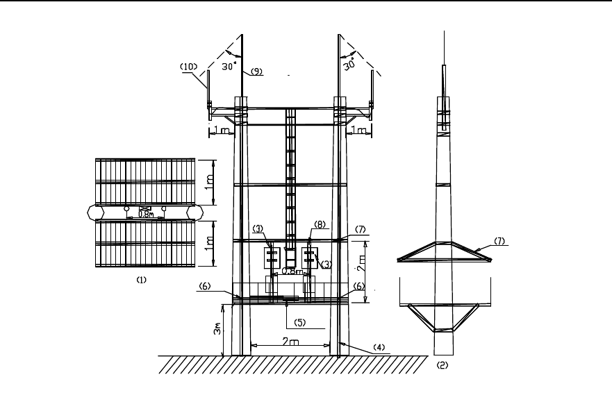
Installation Manual
iSiteC ODU3601C CDMA Soft Base Station Chapter 2 Installing Cabinet Hardware
2-8
1) Top view 2) Side view 3) ODU3601C
4) Lightning protection grounding flat steel 5) Grounding bar 6) Soldering point
7) Sun-shading cover 8) Holding support 9) Lightning arrester
10) Omni antenna
Figure 2-5 Installing ODU3601C on two poles
III. Note
l To facilitate the introduction of power cables and trunk cables, first determine the
metal holding support on which the ODU3601C is to be installed. IAFB or AC
lightning protection box can be installed below the ODU3601C. The IABB can be
fixed on the platform directly. If more than 2 battery boxes are needed, a platform
should be established below the platform.
l Equipment like the ODU3601C, IAFB, UPS, etc. should be installed between two
poles via metal parts. It is not allowed to directly install them on poles.
l When feeders are used, the antenna jumpers should be bound on the crosspieces
of poles via cable ties. For the convenience of feeder connector preparation and
maintenance, it is prohibited to lay feeders transversely. The feeders should be
routed along the sides of the cabling rack.
l If the poles are not long enough, it is recommended to connect the antenna and
the ODU3601C via jumper. And the jumper should be bound at the sides of the
cabling rack and on the crosspieces of poles via cable ties. Both ends of the
jumper should be grounded.
l Lightning arresters should be respectively installed on two poles, and the antenna
of the ODU3601C should be in the protection range of the two arresters (pitch

Installation Manual
iSiteC ODU3601C CDMA Soft Base Station Chapter 2 Installing Cabinet Hardware
2-9
angle 30°C between them), as shown in Figure 2-5. The 40mm%4mm
hot-gavanlizing flat steel should be used as the downleads of arresters.
l The external shielding layer of the ODU3601C antenna and feeder should be
grounded at the bottom of the antenna and at the front end beofore they are
connected to the ODU3601C. The grounding cable should be connected to the
cabling ladder or other metal grounding parts. The grounding cable should be
made of yellow-green (or black) plastic insulation copper wire with the core
diameter not less than 6mm2.
l Grounding bar can be installed on the metal holding support, or fixing beam, or
platform directly and reliable electric connection should be achieved among the
grounding bar and the metal parts aforementioned. A dedicated grounding
downlead should be installed on the grounding bar and be connected to the
counterpoise.
l Power cables and trunk cables should not be winded or bound on the arresters or
their downleads, instead, these cables should be kept as far as possible from the
downleads of arresters. Power cables and signal cables should be distributed
horizontally and the spacing between any two cables should be at least 5cm. And
they should not be routed vertically and crossly.
2.2.4 Example of Metal Mast Installation on Building-top
Such installation of ODU3601C is applied for the coverage of villages and towns.
I. Facility requirements
l For an omni BTS, 3 masts should be used (one is used to install the lightning
arrester and the other two to install two monopole omni antennae. The spacing
between the latter two masts should be over 4.5m. Two masts are generally used
for a directional BTS, as dual polarization antenna is adopted for the BTS.
l The length of the mast should be determined by the height of the ODU3601C
antenna. However, based on the conditions on building-top, the mast length
should not be more than 8m.
l The mast should be made of steel pipe with sufficient intensity and the dialmeter
from 60mm to 114mm. Each mast must be secured by three steep ropes at least.
l A cabling rack should be installed between the masts on which the antenna is
fixed. Its height should be lower than 1.2m.
l The PGND bar should be fixed to the AC lightning protection box or at the bottom
of the IAFB mast and close to the building wall. Following are three methods to
connect the PGND cables:
a) If the equipment room is located in the building, lead the grounding cable from
the building-top to the grounding bar in the equipment room;
b) Connect the grounding cable to the counterpoise at the building bottom;
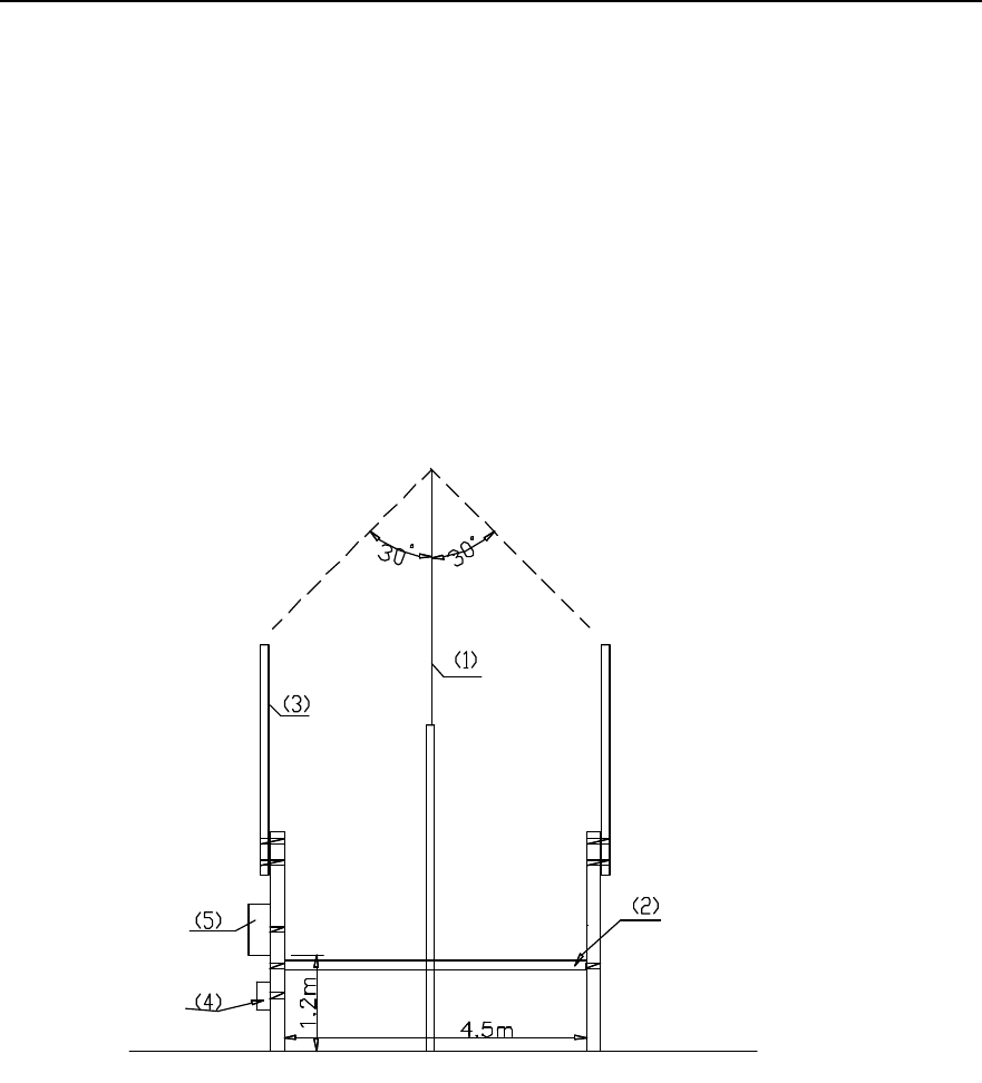
Installation Manual
iSiteC ODU3601C CDMA Soft Base Station Chapter 2 Installing Cabinet Hardware
2-10
c) Connect the grounding cable to the lightning protection zone on the
building-top.
II. Installation layout of an omni ODU3601C
As shown in Figure 2-6, the mast in middle is used to install the lightning arrester; while
in the rest two masts, the one being installed with ODU3601C is called master mast,
and the other is called slave mast.
Antenna jumpers and feeders that are routed upright should be bound on the metal
mast every a specified section (30cm) using black cable ties. The feeder that is routed
on the cabling rack should be fixed using feeder clips every a specified feeder section
(1m~2m).
1) Lightning arrester 2) Cabling Rack 3) Antenna
4) IAFB 5) ODU3601C
Figure 2-6 Omni ODU3601C installation on metal masts
III. Installation layout of a directional ODU3601C
Figure 2-7 shows the installation layout of two ODU3601Cs that are cascaded together.
To facilitate the leading in of the power cable and transmission cable, first determine the
mast on which the upper-level ODU3601C is to be installed. The mast, on which the
ODU3601C is installed, is called master mast, and the one where the ODU3601C is
instaled is called slave mast.
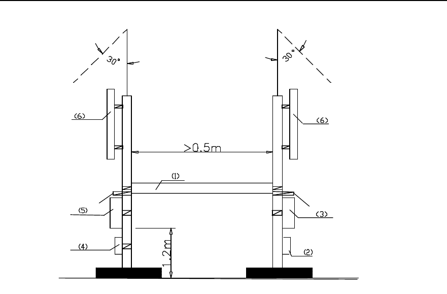
Installation Manual
iSiteC ODU3601C CDMA Soft Base Station Chapter 2 Installing Cabinet Hardware
2-11
1) Cabling rack for feeder 2) IAFB 3) Grounding bar
4) AC lightning protection box 5) ODU3601C 6) Directional antenna
Figure 2-7 Directional ODU3601C installation on metal masts
IV. Note
l For antenna jumper and feeder routed vertically, bind them on the metal masts
with the spacing of 30cm via black cable ties; for antenna feeder routed along the
cabling rack, fix them with the spacing of 1m or 2m via feeder clips.
l Power cables from ODU3601C to ODU3601C should be protected by metal tubes,
and fibers for cascading by currgated tube. Power cables and fibers routed
vertically should be bound on the metal masts via black cable ties, and those
routed horizontally should be bound to the cabling rack.
l Power cables should be distributed along the outer side of the cabling rack, and far
away from the fibers and feeders.
2.2.5 Example of Tower Installation
This mode applies to such locations as fields, villages, towns, and roadsides to cover
villages, roads, etc. In this mode, the hoisting of ODU3601C is involved.
Installation Manual
iSiteC ODU3601C CDMA Soft Base Station Chapter 2 Installing Cabinet Hardware
2-12
Caution:
When hoisting the ODU3601C, try to avoid any collision between ODU3601C and the tower.
I. Layout of tower installation
The tower installation features in simple operation, lower cost and small installation
area. Such installation applies to the coverage of roads and the case that the antenna
needs to be installed over 15m in height.
1) Facility requirements
l The support on which the directional antenna is installed should be extended out
of the platform for at least 0.5m. Proper support length of the omni antenna should
be determined to meet the requirements for the horizontal diversity distance (over
4.5m) between two antennae.
l The diameter of the holding support on which the antenna is installed should be
60mm~114mm. The length (generally, omni antenna: 1m; directional antenna: 3m)
of it should be determined according to the antenna type and sizes.
l A square platform(3m % 3m) should be established 3m above the ground with the
bearer capability more than 500kg. And a sun-shading shed should be established
3m above the platform.
l A 2m holding support should be fixed to the tower body vertically above the
platform so as to install ODU3601C,Lightning arrester, etc. The number of
supports is determined by the number of ODU3601Cs, and the diameter of each
support should be 60mm~114mm.
2) Installation layout
Figure 2-8 shows the layout of ODU3601C installation on tower.
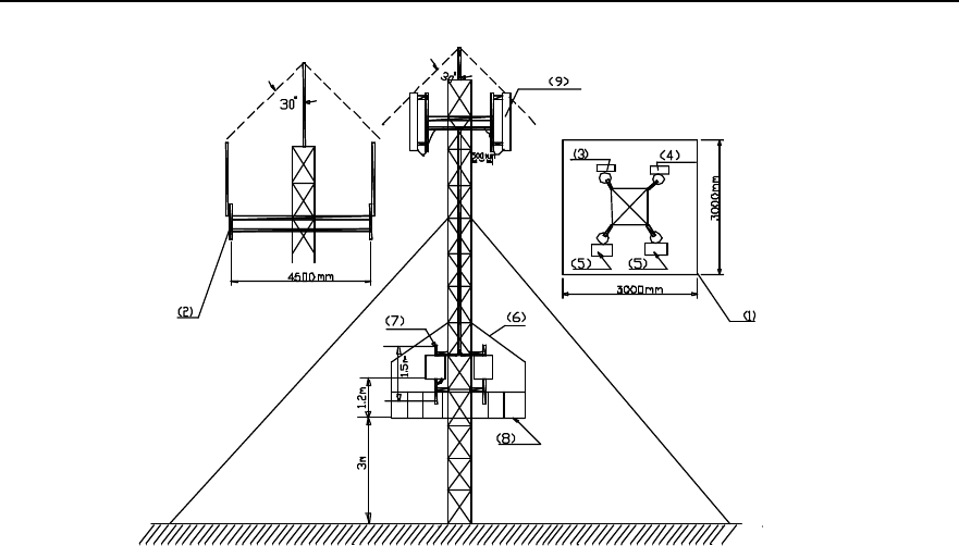
Installation Manual
iSiteC ODU3601C CDMA Soft Base Station Chapter 2 Installing Cabinet Hardware
2-13
1) Top view 2) Side view 3) Lightning arrester
4) Lightning arrester 5) ODU3601C 6) Sun-shading cover
7) Holding support 8) Platform 9) Directional antenna
Figure 2-8 Installing ODU3601C on tower
3) Note
l Distribute feeders along one side of the tower evenly and tidily. And all feeders
should be fixed via feeder dual-clips.
l Install AC lightning protection box and grounding busbar on one support, and the
ODU3601C on the other. If the ODU3601C is cascaded with other ODU3601Cs,
install them on other supports.
l Install PGND bar on the tower directly. And its location should be close (the PGND
cable length should not be more than 1m) to AC lightning protection box. It should
have its dedicated grounding downlead (made of 40mm % 4mm hot-gavanlizing
flat steel). PGND bar and its downlead should be connected via 35mm2
yellow-green plastic insulation copper wire or welded directly. Neither the bar nor
the downlead should be insulated from the tower body.
l The external shielding layer of ODU3601C coaxial feeder should be grounded on
tower top and grounded before the feeder is connected to the ODU3601C. The
grounding cable should be connected to the tower body. The grounding cable
should be made of yellow-green (or black) plastic insulation copper wire with the
core diameter not less than 6mm2.
l Power cables and signal cables of ODU3601C should not be winded or bound on
the tower. They should be cabled as horizontally as possible.

Installation Manual
iSiteC ODU3601C CDMA Soft Base Station Chapter 2 Installing Cabinet Hardware
2-14
II. Self-supporting tower installation
Such installation is generally not recommended due to its high cost. If necessary,
following requirements must be satisfied:
Set up a square platform 3m above the ground inside the tower. The load of this
platform should be 500kg. Besides, a sun-shading cover should be set up 3m above
the platform.
Install a climb ladder along the outer side of the tower to facilitate the installation of
antenna and feeder system. Besides, extend a beam out of the tower every 2m for
feeder distribution.
For other requirements, refer to those available in "I. Layout of tower installation".
2.3 Installing Major Equipment
2.3.1 Installation Flow
Figure 2-9 shows the flow to install ODU3601C major equipment:
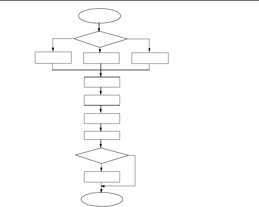
Installation Manual
iSiteC ODU3601C CDMA Soft Base Station Chapter 2 Installing Cabinet Hardware
2-15
Start
Wall
installation Select installation
mode
Metal mast or pole
installation
Install bracket Install plinth Install fastener
set
Install rack
Install modules
Install shell
End
Outdoor installation?
Install sun-shading
cover
Y
N
Install cables
Plinth installation
Figure 2-9 ODU3601C major equipment installation flow
In terms of different installation modes of racks, the ODU3601C installation comprises
wall installation, plinth installation, and metal mast and concrete pole instllation.
Following is to introduce the specific process of the above three modes.
2.3.2 Installing ODU3601C on the Wall
I. Installing bracket
During the installation, a bracket should be installed to secure the ODU3601C onto the
wall. Figure 2-10 shows the installation flow:
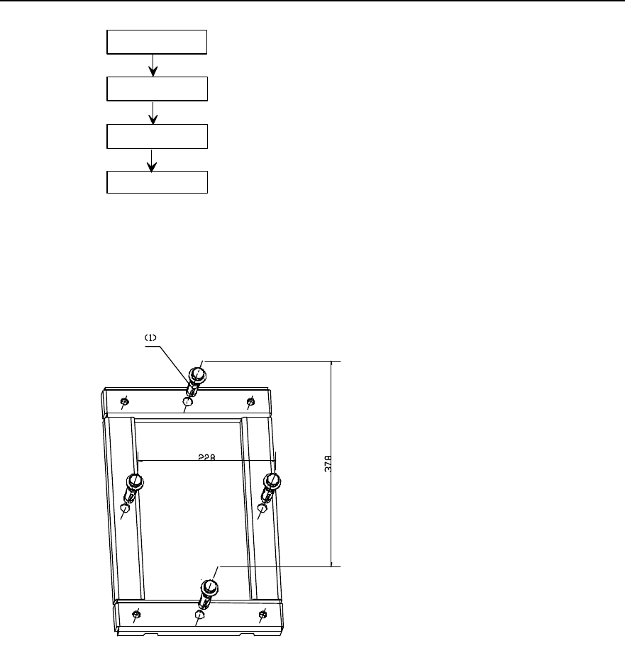
Installation Manual
iSiteC ODU3601C CDMA Soft Base Station Chapter 2 Installing Cabinet Hardware
2-16
Mark
Drill holes
Install expansion bolts
Fix bracket
Figure 2-10 Installing the bracket
1) Position and mark the places on the wall to install expansion bolts. Figure 2-11
shows the appearance of an expansion bolt.
1) M12 expansion bolt
Figure 2-11 Positioning holes
2) Drill holes on the marked places via a percussion drill with the drill bit of v16, the
holes should be 52mm~60mm deep and should have the same depth. After the
drilling, remove the dust inside and outside the holes with a vacuum cleaner, and
then check the distance among holes. Whenever big errors occur, the relevant
hole must be positioned and drilled again.
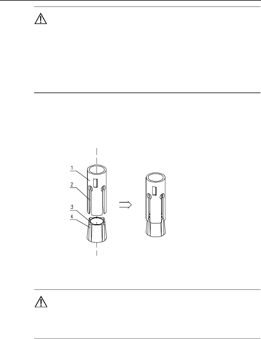
Installation Manual
iSiteC ODU3601C CDMA Soft Base Station Chapter 2 Installing Cabinet Hardware
2-17
Caution:
1) Hold the drilling bit vertical to the wall during drilling. Hold tight the drillstock with two hands to keep it in
the right direction, as vibrations may lead to damaged wall and the hole not straight.
2) The holes should be 52mm~60mm deep and should have the same depth. Otherwise, the expansion
bolts can not be secured.
3) If the wall is too hard and smooth to settle the drill bit, punch a pit with a chisel to help positioning the
hole.
3) Remove the bolt sleeve and nut and put the sleeve and nut vertically into the hole
(before this, the guiding fins should be installed on the slots of the sleeve).
Hammer the bolt sleeve until it completely goes into the ground. Figure 2-12
shows the installation of the bolt sleeve and nut.
1) Bolt sleeve 2) Guiding slot 3) Nut 4) Guiding fin
Figure 2-12 Installation of the bolt sleeve and nut
Caution:
The guiding fins should be installed on the bolt sleeve first. Otherwise, the expansion bolt can not be
properly installed and secured.
4) Put the bracket onto the bolt, and make it droop down naturally. Then mark the
places where the rest three bolts are to be inserted.
5) Drill the holes and install the expansion bolts as mentioned above.
6) Align the bracket with four expansion bolts and put the bracket onto the wall. Then
in turn put insulation coverings, big plain washers, spring washers v12 and M12
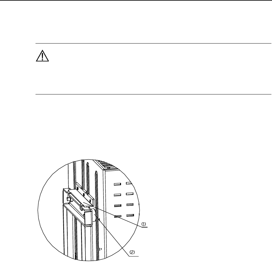
Installation Manual
iSiteC ODU3601C CDMA Soft Base Station Chapter 2 Installing Cabinet Hardware
2-18
nuts on the four bolts, and tighten all four nuts to a torque of 45 N$m so as to make
the expansion bolts expanded and fix the bracket on the wall.
Caution:
Before securing the nuts, put the washers first onto them. The exposed part of the bolt should be about
20mm long.
II. Installing rack
1) Hang the rack onto the bracket, and make the four white washers at the rear of the
rack alligned with four installation holes on the bracket, as shwon in Figure 2-13.
1) Hanger (at the rear of the rack) 2) White washer
Figure 2-13 Installing rack onto bracket
2) Starting from the inside of the rack, secure the two screws at the upper part of the
rack, then the two at the lower part, as shown in Figure 2-14.
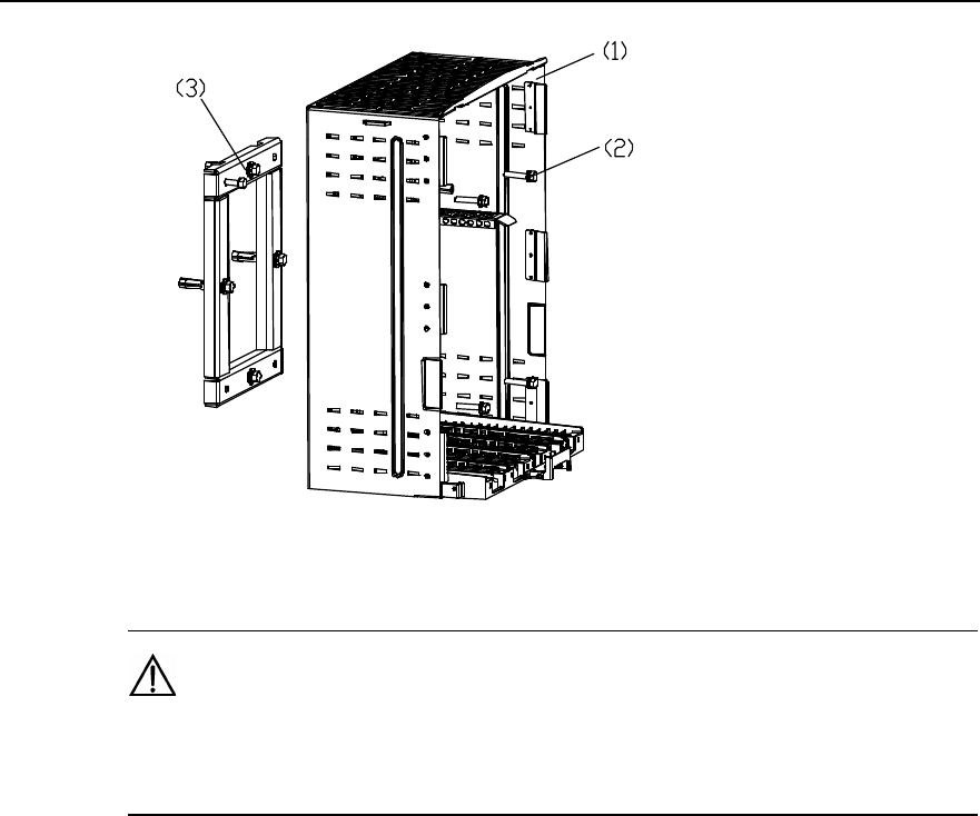
Installation Manual
iSiteC ODU3601C CDMA Soft Base Station Chapter 2 Installing Cabinet Hardware
2-19
1) Rack 2) M10%45 screw 3) Bracket
Figure 2-14 Installing rack onto wall
Caution:
Check the levelness of the rack after the installation and confirm the result not over 1° so as to ensure the
cooling of the MPAM. Otherwise, adjust it till it is OK.
2.3.3 Installing ODU3601C on Plinth
I. Installing plinth
Generally, this mode is applied to the indoor environment.
1) Place the plinth on the floor, and mark the positions of all 4 connection holes of the
plinth on the floor.
2) Drill holes using a percussion drill with the drill bit of v16, and begin to install the
expansion bolts. The installation of expansion bolts is available in the section
“2.3.2 Installing ODU3601C on the Wall”.
3) Lift the plinth by two persons, align it with the four expansion bolts and place it
onto the floor. Confirm the levelness of the plinth and then in turn put insulation
coverings, big plain washers, spring washers v12 and M12 nuts onto the four
expansion bolts. Then alternatively fasten the nuts to a torque of 45 N$m so as to
make the bolts expanded and secure the plinth, as shown in Figure 2-15.
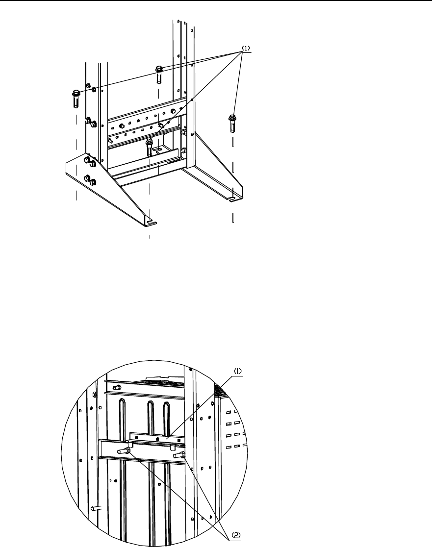
Installation Manual
iSiteC ODU3601C CDMA Soft Base Station Chapter 2 Installing Cabinet Hardware
2-20
1) M12%60 expansion bolt
Figure 2-15 Fixing the plinth
II. Installing rack
1) Align the four white washers at the rear of the rack with the four installation holes
on the plinth, and then place the rack onto the plinth, as shown in Figure 2-16.
1) Hanger (at the rear of the rack) 2) Installation holes on the plinth
Figure 2-16 Placing rack onto plinth
2) Starting from the inside of the rack, fasten the two screws at the upper part of the
rack, then the two at the lower part, as shown in Figure 2-17.
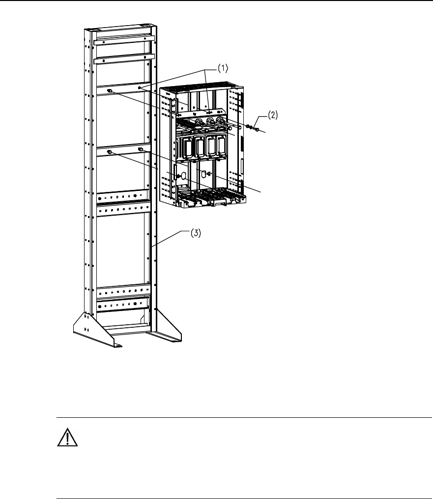
Installation Manual
iSiteC ODU3601C CDMA Soft Base Station Chapter 2 Installing Cabinet Hardware
2-21
1) Installation hole 2) M10%50 bolt 3) Plinth
Figure 2-17 Securing rack onto plinth
Caution:
Check the levelness of the rack after the installation and confirm the result not over 1° so as to ensure the
cooling of the MPAM. Otherwise, adjust it till it is OK.
2.3.4 Installing ODU3601C on Metal Mast and Concrete Pole
I. Installing fastener sets
This installation mode comprises ODU3601C installation on metal masts and poles. To
fix the rack onto them, fastener sets should be installed first.
1) Fix the fastener set 1 with M10 bolt onto the upper part of the holding support, then
the fastener set 2 onto the lower part of the mast or pole.
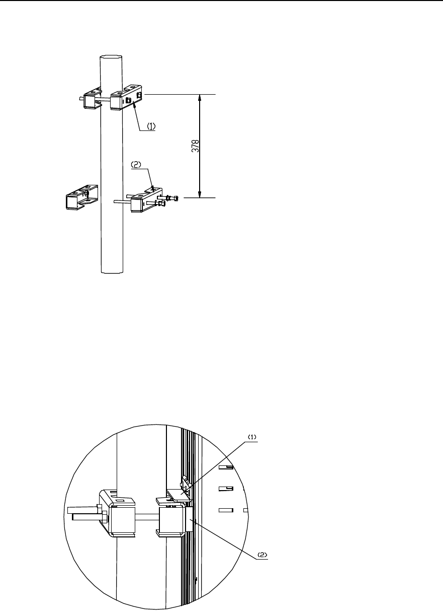
Installation Manual
iSiteC ODU3601C CDMA Soft Base Station Chapter 2 Installing Cabinet Hardware
2-22
2) Adjust the spacing between the center points of two fastener sets to 378mm, as
shown in Figure 2-18.
1) Fastener set 1 2) Fastener set 2
Figure 2-18 Installing fastener sets
II. Installing rack
1) Align the four white washers at the rear of the rack with the four installation holes
on the fastener sets and then place the rack into the slots of two fastener sets, as
shown in Figure 2-19.
1) Hanger (at the rear of the rack) 2) White washer
Figure 2-19 Fixing rack with fasteners
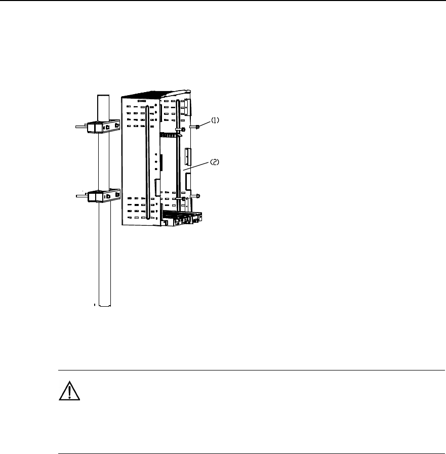
Installation Manual
iSiteC ODU3601C CDMA Soft Base Station Chapter 2 Installing Cabinet Hardware
2-23
2) Starting from the inside of the rack, install the two M4%45 screws at the upper part
of the rack, then check the correspondence between the two screws (at the lower
part) and the fastener set 2. If OK, tighen the screws; otherwise, adjust the position
of fastener set 2, as shown in Figure 2-20.
1) M4%45 screw 2) Rack
Figure 2-20 Fixing the rack
Caution:
Check the levelness of the rack after the installation and confirm the result not over 1° so as to ensure the
cooling of the MPAM. Otherwise, adjust it till it is OK.
2.3.5 Installing Modules
Modules of ODU3601C are generally installed by the sequence from right to left, i.e.
MPAM-MFEM-MTRM-MAPM. During the installation, refer to their names on the front
of the modules and the corresponding names on the backplane, then insert them into
the corresponding slots.
Figure 2-21 shows the installation flow of modules.
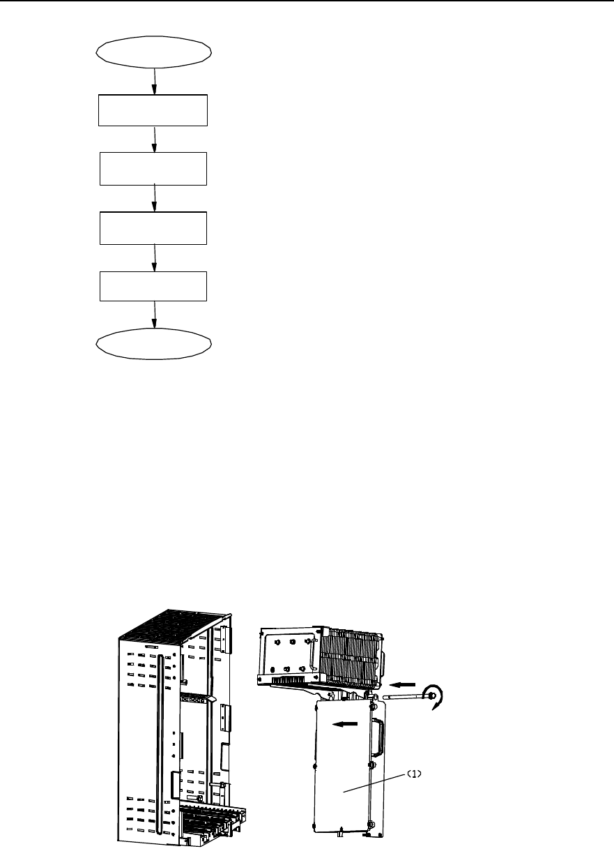
Installation Manual
iSiteC ODU3601C CDMA Soft Base Station Chapter 2 Installing Cabinet Hardware
2-24
Start
Install MFEM
Install MTRM
Install MPAM
End
Install MAPM
Figure 2-21 Module installation flow
All modules are installed as per the same process. Following is to describe the
installation process of the MPAM as an example.
1) Hold the bottom of the MPAM with the left hand, and the handle of the MPAM with
the right hand, then insert it into the position along the guide rail.
2) Tighten the M10 bolts at the upper part of the module and the two M6 fixing bolts at
the lower part alternatively for module fixation and waterproof, as shown in Figure
2-22.
1) MPAM
Figure 2-22 Installing MPAM
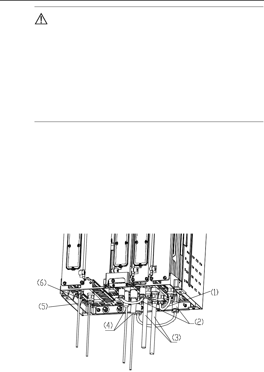
Installation Manual
iSiteC ODU3601C CDMA Soft Base Station Chapter 2 Installing Cabinet Hardware
2-25
Caution:
1) Two persons are required during the installation as heat-pipe radiator has been installed onto the
MPAM before delivery and the MPAM is heavy. If the heat-pipe radiator interferes with the support for the
radiator on the rack, remove the support first and then install it back to position after the installation.
2) Open the maintenance window on the panel of the installed MTRM so as to configure the TRX_ID DIP
switch according to the cascading level of the ODU3601C. In particular, use the default configuration of the
lower three bits, i.e. "000", indicating this ODU3601C is of the first level; if the lower three bits are set to
"001", this ODU3601C is of the second level, and so on. Anyway, the configuration of the TRX_ID DIP
Switch must be made in accordance with the actual cascading level of the ODU3601C. Otherwise this
ODU3601C is unworkable.
3) In turn, install MFEM, MTRM and MAPM. The procedures are the same as those
of MPAM.
2.3.6 Installing Cables
I. Cable types
At the site, such cables should be connected for the ODU3601C as Radio Frequency
(RF) jumpers, Frequency Hopping (FH) cables, external cables, fibers, etc. Figure 2-23
shows the entire cable distribution of the ODU3601C.
1) Inter-module cables between
Type N male connectors 2) Cables connecting Type D connectors
between modules 3) Antenna feeder DIN connector
connecting to feeder
4) MTRM fiber cascading connector 5) AC power input cable 6) DC input power cable of battery
Figure 2-23 ODU3601C cable connection
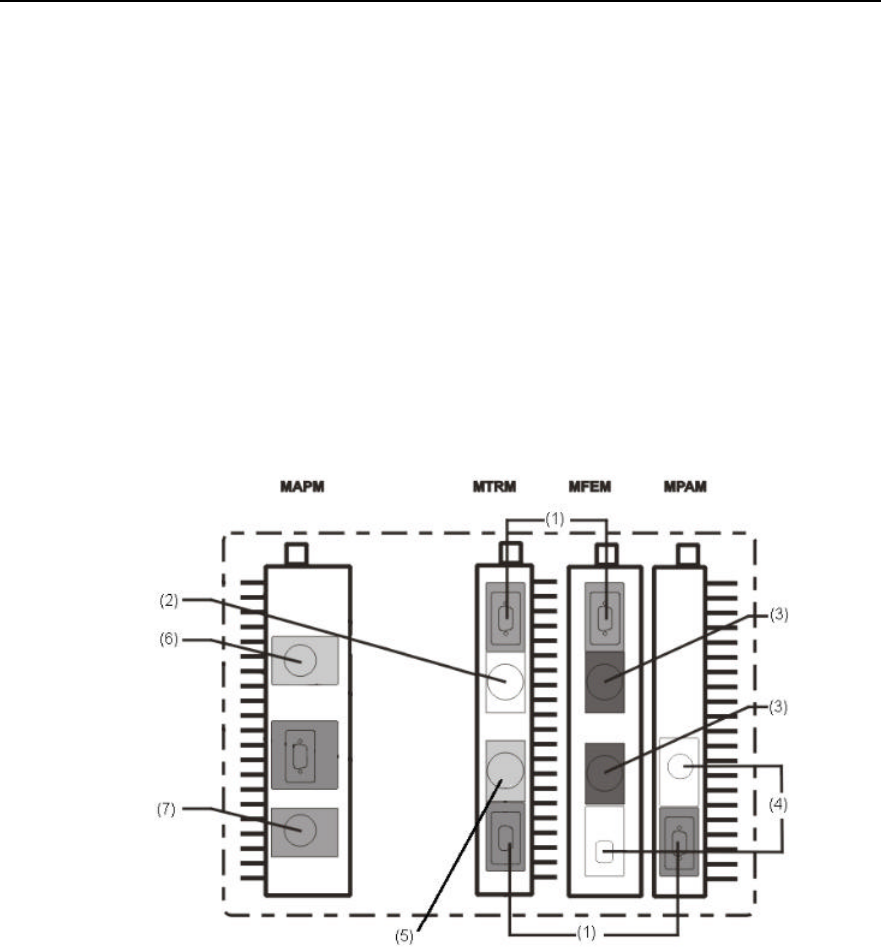
Installation Manual
iSiteC ODU3601C CDMA Soft Base Station Chapter 2 Installing Cabinet Hardware
2-26
Following are the details of the cable distribution of modules:
1) Inter-module RF jumpers
l RF jumper (Type D connector) between MTRM and MFEM;
l RF jumper (Type D connector) between MPAM and MTRM;
l RF jumper (Type N connector) between MPAM and MFEM;
2) External cables and fiber
l RF jumpers (DIN connector) connecting to the antenna feeder interface of the
MFEM;
l Fiber cascading connector (waterproof fiber connector) connected with MTRM
fiber interface;
l Power cable connecting to MAPM;
l Grounding cable between cabinet and PGND bar.
Figure 2-24 shows the cable distribution at the bottoms of ODU3601C modules.
1) Cables connecting Type D
connectors between modules. 2) MTRM fiber cascading
connector 3) Antenna feeder DIN
connector connecting to feeder
4) Inter-module cable between
Type N male connectors 5) Connector connecting MTRM
to the upper-level fiber 6) AC power input cable
7) DC input power cable of battery
Figure 2-24 Cable distribution at the bottom of ODU3601C
II. Cabling sequence
Waterproof measures and bottom lead-out mode is adopted during the cable
distribution of the ODU3601C. And the distribution follows the sequence inside-outside:
1) Connect RF jumper between MPAM and MTRM, and fasten it with straight
screwdriver;
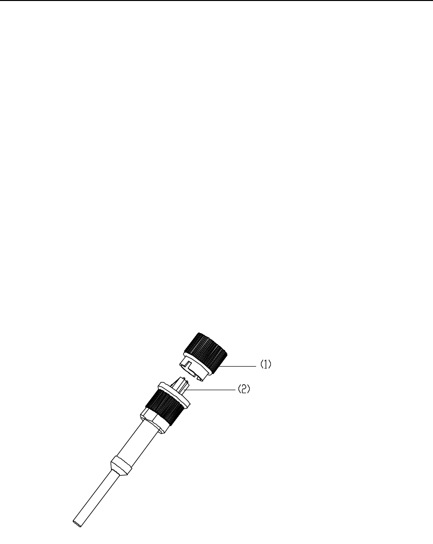
Installation Manual
iSiteC ODU3601C CDMA Soft Base Station Chapter 2 Installing Cabinet Hardware
2-27
2) Connect RF jumper between MPAM and MFEM and make waterproof treatment
for the connector via two types of tapes;
3) Connect DIN RF jumper from the antenna and feeder interface of MFEM to the
feeder and take waterproof measures for the connector via two types of tapes;
4) Connect Type N RF jumper between MFEM and MPAM and take waterproof
measures for the connector via two types of tapes;
5) Connect the upper-level fiber to the fiber interface with the silk-screen "UP-FIBER"
at the bottom of MTRM. If fiber cascading is necessary, connect the fiber
cascading connector to the cascading fiber interface of the MTRM (The silkscreen
"DOWN_FIBER" is made on the bottom of the cascading fiber interface);
6) Connect RF jumpes respectively from MTRM to MFEM, then fasten them with
straight screwdriver;
7) Connect power cables to MAPM;
8) Connect grounding cables between the cabinet and the PGND bar.
III. Procedures to distribute the waterproof fibers at the bottom of MTRM
During the distribution, be careful not to break the core wire of the fiber connector.
1) Unfix the dustproof cover on the waterproof fiber, and make the dual-LC fiber
connector exposed, as shown in Figure 2-25.
1) Dustproof cover 2) Dual-LC fiber connector
Figure 2-25 Appearance of waterproof fiber (figure 1)
2) Unwrap the limit pivoted arm, as shown in Figure 2-26.
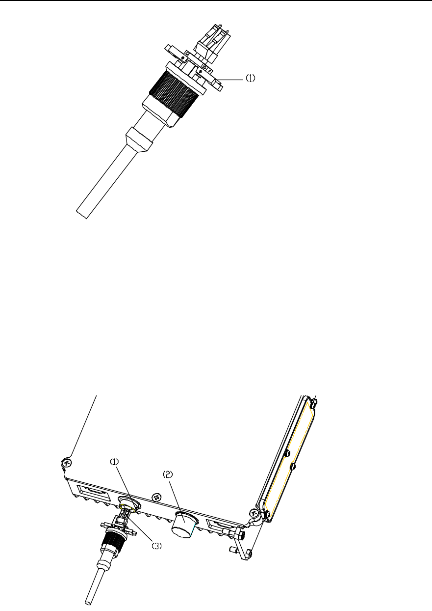
Installation Manual
iSiteC ODU3601C CDMA Soft Base Station Chapter 2 Installing Cabinet Hardware
2-28
1) Limit pivoted arm
Figure 2-26 Appearance of waterproof fiber (figure 2)
3) Unfix the waterproof cover from the MTRM fiber interface; align the dual-LC fiber
connector with the fiber interface. Make the limit pivoted arm correspond to the
locating slot of the fiber interface. Then insert the connector into the fiber interface
gently until a sound is heard indicating that the connector is in position, as shown
in Figure 2-27.
1) Fiber connector locating slot 2) waterproof cover 3) Dual-LC fiber connector
Figure 2-27 Installing waterproof fiber (1)
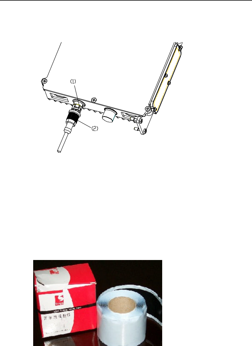
Installation Manual
iSiteC ODU3601C CDMA Soft Base Station Chapter 2 Installing Cabinet Hardware
2-29
4) Fix the limit pivoted arm into the corresponding locating slot and tighten the
external nut. The installation is then complete. See Figure 2-28.
1) Fixing the limit pivoted arm into the locating slot 2) External nut
Figure 2-28 Installing waterproof fiber (2)
IV. Waterproof measures
Except the power cable connectors, fibers and Type D connectors, waterproof
measures should be taken for Type N/DIN connectors. There are two types of
waterproof tape needed: waterproof insulation tape and PVC tape, as shown in Figure
2-29 and Figure 2-30.
Figure 2-29 Waterproof insulation tape
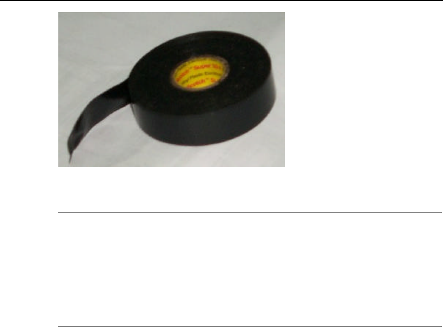
Installation Manual
iSiteC ODU3601C CDMA Soft Base Station Chapter 2 Installing Cabinet Hardware
2-30
Figure 2-30 PVC tape
&
Note:
1) Seal the connector a s follows: Wrap it up with waterproof insulation tape, and then with PVC tape. When
wrapping, do it from the bottom up, then from the top to the bottom and finally from the bottom up again.
Each turn should be overlapped by the next turn for about one-third of the width.
2) For the convenience of removing in maintenance, it is recommended to wrap first innermost part of the
connector with PVC tape, then with waterproof insulation tape.
2.3.7 Installing Shell
During the software installation and system commissioning, it may be required to view
the operation status of modules via maintenance window, so the installation of shell
should be carried out after the system commissioning.
Procedure is as follows:
1) Align the two hookers at the top of the plastic shell with the two jacks at the top of
the back installation plate assembly, then gently push the shell in by pressing the
two sides of the shell until the shell completely matches the back shell.
2) Tighten the fixing bolts at the two sides of the back installation plate assembly.
3) Get them locked.
Figure 2-31 shows the whole installation.
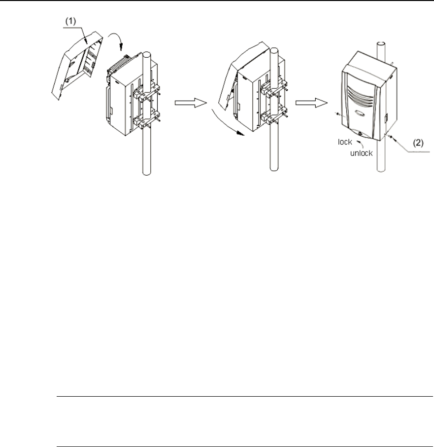
Installation Manual
iSiteC ODU3601C CDMA Soft Base Station Chapter 2 Installing Cabinet Hardware
2-31
1) Plastic shell 2) Bolt
Figure 2-31 Installing the shell
2.3.8 Installing Sun-shading Cover
If the ODU3601C is located outdoors, the sun-shading cover should be installed. The
cover should be installed above the ODU3601C and fixed onto the same metal mast
with the ODU3601C via metal holding hoops. The bottom of the cover should be
50~100mm away from the top of the ODU3601C. Method to install the cover is almost
the same with that to install the ODU3601C rack onto metal masts. Please refer to
contents related.
&
Note:
Sun-shading cover is optional according to the actual environment of the site.
2.4 Installing Auxiliary Equipment
Auxiliary equipment includes IAFB, AC lightning protection box, the IABB, UPS, etc. In
different projects, different auxiliary equipment will be adopted. Following are to
introduce the methods to install certain auxiliary equipment first, then the methods to
connect their cables in terms of different projects.
2.4.1 Installing IAFB
IAFB provides the ODU3601C with certain auxiliary functions and integrates most of
the auxiliary equipment inside a box. Figure 2-32 shows the appearance of an IAFB.
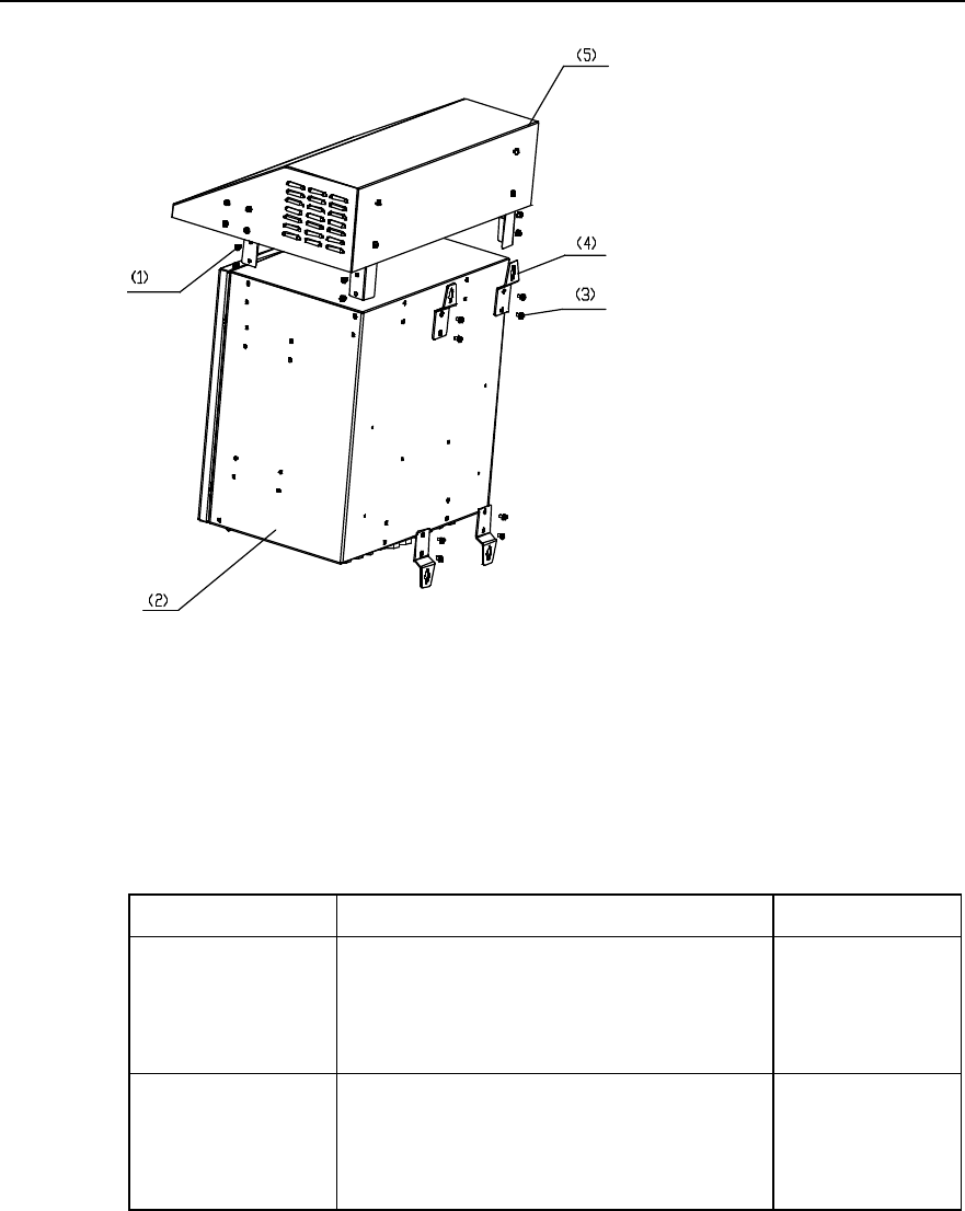
Installation Manual
iSiteC ODU3601C CDMA Soft Base Station Chapter 2 Installing Cabinet Hardware
2-32
1) M6%12 bolt 2) Box 3) M6%12 bolt 4) Hanger 5) Sun-shading cover
Figure 2-32 IAFB appearance
IAFB comprises two types: One applies to southern environment and the other to
northern environment. Table 2-1 shows their respective configurations.
Table 2-1 IAFB description
IAFB type Configuration Applicable Scope
One applying to southern
environment
AC lightning protection box
Power module for transmission
Various lightning arresters for transmission
Various power distribution terminals and air switches
Optical Distribution Frame (ODF) \Digital Distribution
Frame (DDF)
Applicable to various
envrionment
One applying to northern
environment
AC lightning protection box
Power module for transmission
Various lightning arresters for transmission
Various power distribution terminals and air switches
ODF\DDF
Hot plate
Applicable to cold
areas
Three modes are available to install an IAFB, namely, intalling it on walls, metal masts
(with the diameter v60~v114) or poles (with the diameter v150~v350). The detailed
installation procedures are available in Appendix A.
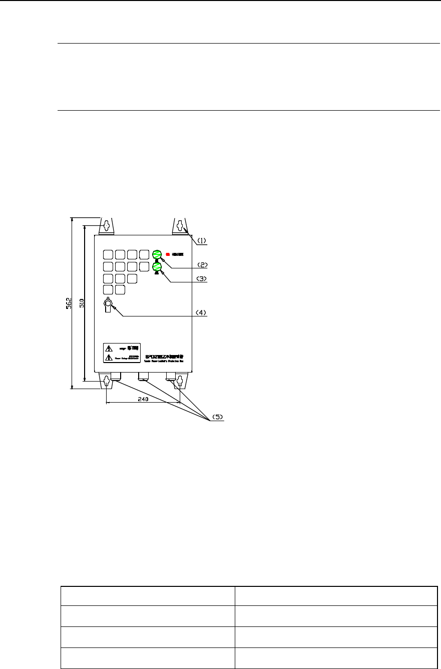
Installation Manual
iSiteC ODU3601C CDMA Soft Base Station Chapter 2 Installing Cabinet Hardware
2-33
2.4.2 Installing AC Lightning Protection Box
&
Note:
In terms of its discharging currents, the AC lightning protection box can be classified into three types: 20kA,
40kA and 100kA. All boxes mentioned in this chapter are of 20kA.
I. Structure
AC lightning protection box prevents the AC input power supply from lightning strikes.
Its appearance is shown in Figure 2-33.
1) Hanger 2) RUN indicator 1 3) RUN indicator 2
4) Door lock 5) Cabling hole
Figure 2-33 AC lightning protection box appearance
There are two indicators on the door of the box. The significance of two indicators
depends on the positions of the air switch inside the box. If the switch is off, the
indicators run normally. Otherwise, the indicators will be both off, and the lightning
protection box will be invalid. Table 2-2 shows the meanings of indicator statuses.
Table 2-2 Meanings of AC lightning protection box indicators
RUN indicator status Meaning
RUN indicator 1: On;
RUN indicator 2: On. Lightning protection function normal
RUN indicator1: Off;
RUN indicator2: On C-level lightning protection function disabled
RUN indicator 1: On;
RUN indicator 2: Off D-level lightning protection function disabled
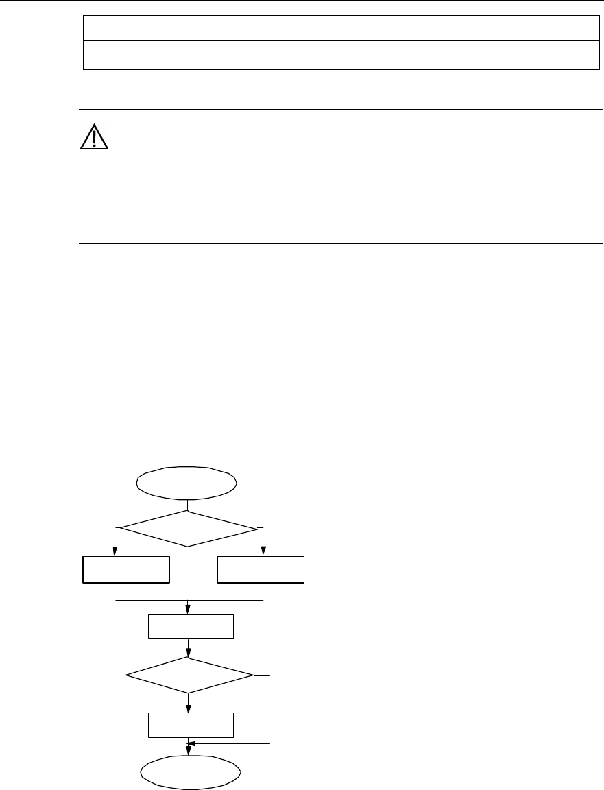
Installation Manual
iSiteC ODU3601C CDMA Soft Base Station Chapter 2 Installing Cabinet Hardware
2-34
RUN indicator status Meaning
RUN indicator 1: Off;
RUN indicator 2: Off Lightning protection function disabled (except for the
interruption of external power supply)
Caution:
If either of the two RUN indicators is off, it indicates that the lightning protection box runs abnormally.
Please contact Huawei engineers at once. Otherwise the related equipment may suffer from lightning
strikes.
II. Method
Three modes are available to install an IAFB, namely, intalling it on walls, metal masts
(with the diameter v60~v114) or poles (with the diameter v150~v350).
III. Installation flow
Figure 2-34 shows the installation flow of AC lightning protection box.
Start
Install AC lightning
protection box
Install sun-
shading cover
End
Wall
installation Metal mast or pole
installation
Install fastenerInstall bolts
Outdoor
installation?
Y
N
Select installation
mode
Figure 2-34 Installation flow of AC lightning protection box

Installation Manual
iSiteC ODU3601C CDMA Soft Base Station Chapter 2 Installing Cabinet Hardware
2-35
IV. Procedures
Installing the box on wall
1) Put the lightning protection box against the wall and mark the positions where the
four expansion bolts are to be installed. The sizes of holes for expansion bolts are
shown in Figure 2-33.
2) Drll holes with a percussion drill (drill bit v10) at the marked position on the wall.
After the drilling, remove the dust inside and outside the holes with a vacuum
cleaner, and then check the distance among the holes. Whenever big errors occur,
the relevant hole must be relocated and drilled again.
Caution:
1) Hold the drilling bit vertical to the wall during drilling. Hold tight the drillstock with two hands to keep it in
the right direction, as vibrations may lead to damaged wall and the hole not straight.
2) The hole depth should be the length of the expansion bolt sleeve plus the drill bit. The hole depths of
respective holes should be consistent. Before measuring the hole depth, remove the dust inside the hole
and measure the hole depth. Remove the dust with a vacuum cleaner before drilling.
3) If the wall is too hard and smooth to settle the drill bit, punch a pit with a chisel to help positioning the
hole.
3) Unfix the washer and nut from the expansion M8%80 bolt, put the expansion bolt
and the expansion sleeve vertically into the hole and strike the bolt with a rubber
hammer until the expansion sleeve is completely driven in the hole.
4) Pull the four expansion bolts through the four hangers of the box.
5) Put the plain washers, spring washers, and nuts onto the exapnsion bolts, revise
the location of the box, and tighten the nuts to a torque of 13.4 N$m. Figure 2-35
shows the whole process.
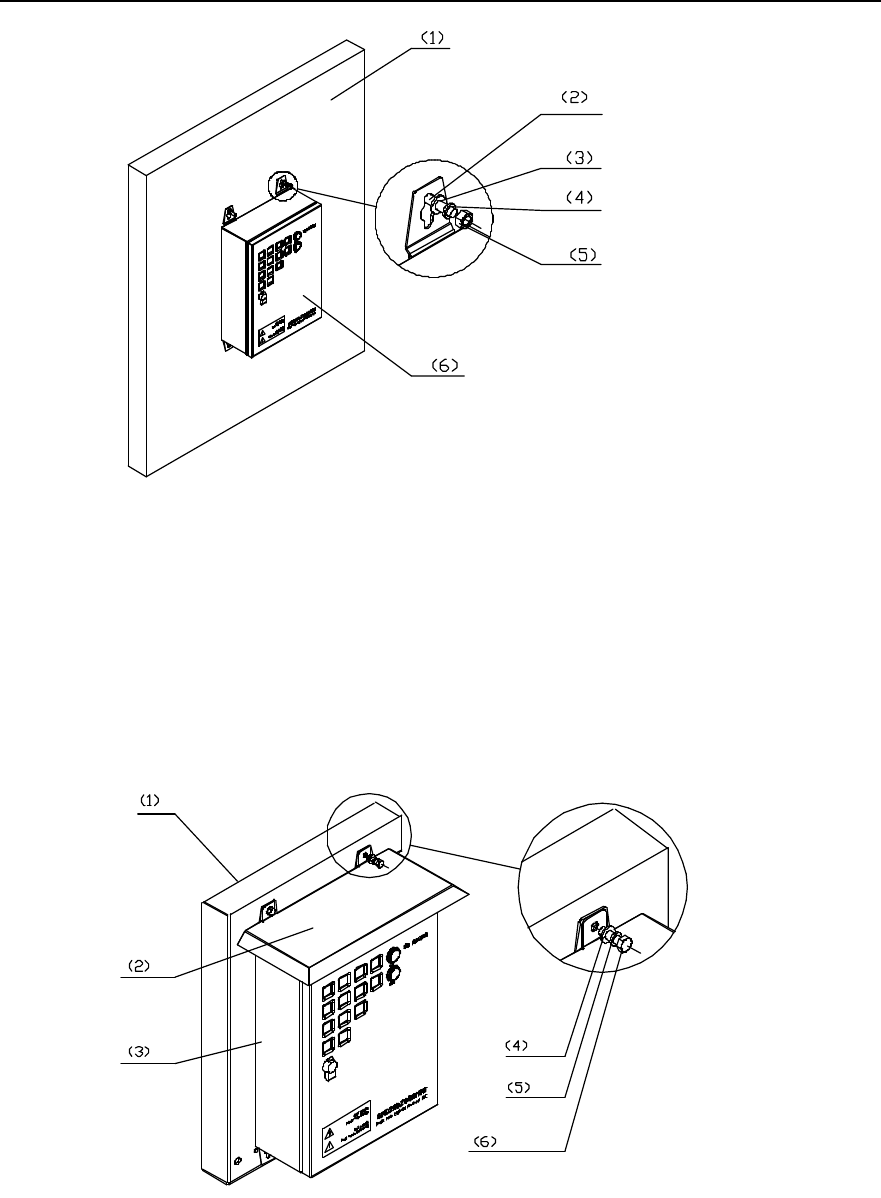
Installation Manual
iSiteC ODU3601C CDMA Soft Base Station Chapter 2 Installing Cabinet Hardware
2-36
1) Wall 2) M8%80 expansion bolt 3) Plain washer 8
4) Spring washer 8 5) Nut M8 6) AC lightning protection box
Figure 2-35 Fixing AC lightning protection box (on wall)
6) If a sun-shading cover (applicable to outdoor AC lightning protection box) is
necessary, please align the installation holes of the cover with the upper two
expansion bolts, then in turn put plain washers, spring washers and nuts onto the
expansion bolts, and then revise the location of the box, finally, tighten the nuts to
a torque of 13.4 N$m. Figure 2-36 shows the process.
1) Wall 2) Sun-shading cover 3) AC lightning protection box
4) Plain washer 8 5) Spring washer 6) Nut M8
Figure 2-36 Installing sun-shading cover for AC lightning protection box
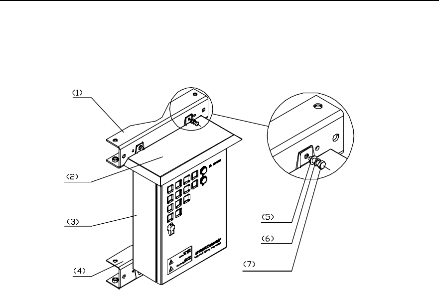
Installation Manual
iSiteC ODU3601C CDMA Soft Base Station Chapter 2 Installing Cabinet Hardware
2-37
Installing the box on metal mast:
1) Fix the AC lightning protection box, sun-shading cover, and beam together with
M8%25 expansion bolts, spring washers, and plain washers, as shown in Figure
2-37.
1) Beam 2) Sun-shading cover 3) AC lightning protection box 4) Beam
5) Plain washer 8 6) Spring washer 7) M8%25 expansion bolt
Figure 2-37 Fixing the box on beams
2) Put the fixed beam and the box against the metal mast, intall the fasteners and
place the mast on the middle of the beam and the fastener. Then pull the M10 bolt
througth the beam and the fastener, put plain washers, spring washers and nuts
onto the bolt and tighten the nut to a torque of 26.5 N$m with a spanner. The
process is shown in Figure 2-38.
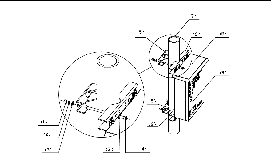
Installation Manual
iSiteC ODU3601C CDMA Soft Base Station Chapter 2 Installing Cabinet Hardware
2-38
1) Nut M10 2) Spring washer 10 3) Plain washer 10
4) M10 bolt 5) Fastener 6) Beam
7) Metal mast 8) Sun-shading cover 9) AC lightning protection box
Figure 2-38 Fixing AC lightning protection box (on metal masts)
Installing the box on pole
1) Fix the box, flashing board and the beam together with M8%25 bolts, spring
washers, plain washers, as shown in Figure 2-37.
2) Place the fixed beam and the box together against the pole. At the other side of the
pole, install another beam and get the pole at the middle between two beams.
Then pull the M12 bolts through the two beams, put plain washers, spring washers
and nuts onto the bolts, and tighten the nuts to a torque of 45 N$m with a spanner,
as shown in Figure 2-39. If the pole is a little bit thin, cut the exposed bolts to keep
the length of the exposed part about 20mm.
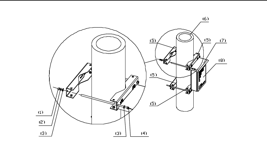
Installation Manual
iSiteC ODU3601C CDMA Soft Base Station Chapter 2 Installing Cabinet Hardware
2-39
1) Nut M12 2) Spring washer 12 3) Plain washer 12 4) M12 bolt
5) Beam 6) Pole 7) Sun-shading cover 8) AC lightning protection box
Figure 2-39 Fixing AC lightning protection box (on pole)
2.4.3 Installing UPS
Generally, there are four modes to install a UPS, i.e. on ground base, wall, metal mast
(with the diameter of v60~v114) or pole (with the diameter of v150~v350).
The detailed installation method of UPS is available in the installation guide of the UPS
supplier.
2.4.4 Installing IABB
I. Structure
The box provents the backup battery groups of ODU3601C from being damaged so as
to provide the ODU3601C with backup power. Its structure is similar to that of
ODU3601C and IAFB.
Inside the box, 6 batteries can be installed. When the box is used independently, only
two batteries are used generally. When the box works together with the UPS, the 6
batteries of it are used. Following are the technical items of the battery:
l Voltage rating of a battery is 12V. When 6 batteries are in series, the voltage rating
is 72V.
l Capacity rating: 26Ah.
l Work temperature: -15°C~+45°C
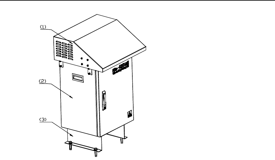
Installation Manual
iSiteC ODU3601C CDMA Soft Base Station Chapter 2 Installing Cabinet Hardware
2-40
1) Sun-shading cover 2) Box 3) Support
Figure 2-40 IABB appearance
II. Method
The box can be installed on the concrete floor or metal platform, instead of on holding
support or wall.
III. Installation flow
Figure 2-41 shows the installation flow of the IABB.
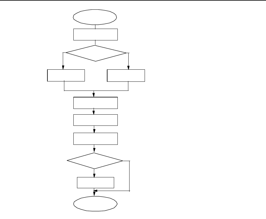
Installation Manual
iSiteC ODU3601C CDMA Soft Base Station Chapter 2 Installing Cabinet Hardware
2-41
Start
Concrete ground
installation Steel workbench
installation
Install support
Fix box
Install sun-
shading cover
End
Drill holes on
concrete ground
Drill holes on steel
workbench
Outdoor
insdtallation?
Y
N
Install expansion
bolts
Install batteries and
connect cables
Select installation
mode
Figure 2-41 Installation flow of the IABB
IV. Procedures
Installing the box on concrete floor:
1) Install the fixing support onto the battery box via 4 M12%20 assembling bolts, as
shown in Figure 2-42.
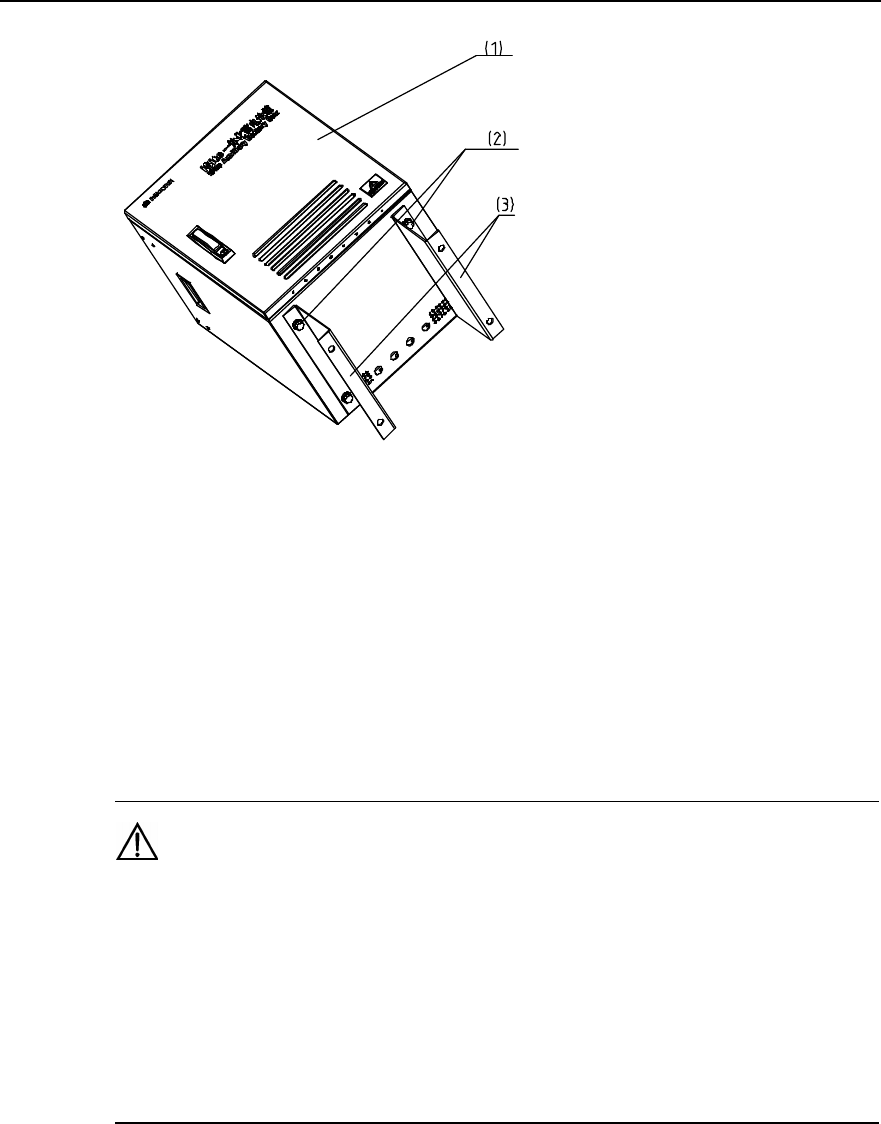
Installation Manual
iSiteC ODU3601C CDMA Soft Base Station Chapter 2 Installing Cabinet Hardware
2-42
1) Box 2) M12%20 bolt, spring washer, plain washer 3) Fixing support
Figure 2-42 Installing the fixing support
2) Place the box onto the floor and mark the places on the floor where all 4
connection holes on the support are located.
3) Drill holes on the floor via a percussion drill with the drill bit of v16. After the drilling,
remove the dust inside and outside the holes with a vacuum cleaner, and then
check the distance among the holes. Whenever big errors occur, the relevant
holes must be relocated and drilled again.
Caution:
1) Hold the drilling bit vertical to the floor during drilling. Hold tight the drillstock with two hands to keep it in
the right direction, as vibrations may lead to damaged floor and the hole not straight.
2) The hole depth should be the length of the expansion bolt sleeve plus the drill bit. The hole depths of
respective holes should be consistent. Before measuring the hole depth, remove the dust inside the hole
and measure the hole depth. Remove the dust with a vacuum cleaner before drilling.
3) If the floor is too hard and smooth to settle the drill bit, punch a pit with a chisel to help positioning the
hole.
4) Unfix the spring washer, nut and plain washer. Put the expansion bolt into the hole
and knock directly on the bolt with a hammer (such as nail hammer) until the bolt is
completely driven into the floor. Then, put the nut on the bolt and tighten it until the
bolt is expanded slightly so as to avoid it getting loose.
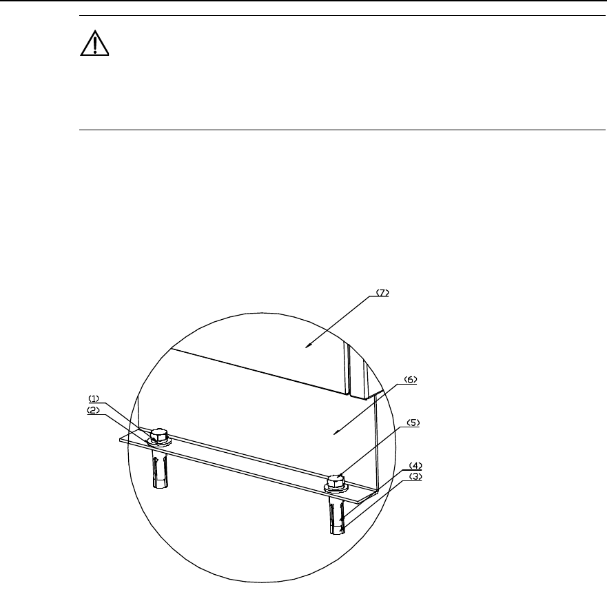
Installation Manual
iSiteC ODU3601C CDMA Soft Base Station Chapter 2 Installing Cabinet Hardware
2-43
Caution:
The proper length of the hole should be 55mm~65mm. Otherwise, the expansion bolt cannot be
completely driven into the hole, which affects the reliability of the box.
5) Put in turn spring washers, and plain washers onto 4 M12%60 bolts, and pull 4
bolts through the holes at the bottom of the support, then put expansion sleeves
and nuts onto the bolts. And then put the bolts into the holes made on the concrete
floor and tighten the bolts with a spanner, as shown in Figure 2-43. Therefore, the
box is secured on the floor.
1) Spring washer 2) Plain washer 3) Expansion bolt 4) Expansion sleeve
5) Bolt 6) Support 7) Box
Figure 2-43 Fixing the box onto the concrete floor
6) Open the door of the box and place the batteries into the box. The box comprises
three layers, each of which can hold two batteries.
7) Connect 6 batteries in series via the cables delivered with the box, as shown in
Figure 2-44.
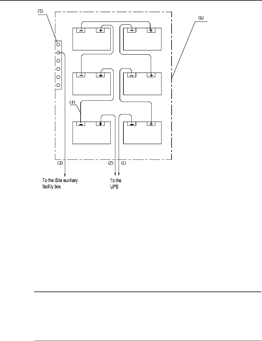
Installation Manual
iSiteC ODU3601C CDMA Soft Base Station Chapter 2 Installing Cabinet Hardware
2-44
1) UPS with power cable (negative cable) 2) UPS with power cable (positive) 3) Grounding cable
4) Battery cable 5) PGND bar in the battery box 6) Battery box
Figure 2-44 Connecting UPS to the IABB
8) Check whether the voltage of battery groups are over 72V with a multimeter. If Yes,
it indicates the installation is OK. Otherwise, errors exist in the installation. Check
the polarities of the batteries and make sure they are OK. If the errors still cannot
be located and the voltage is lower than 72V, it indicates errors exist in the battery
cables or batteries themselves. Please contact Huawei engineers.
&
Note:
When the IABB is used without being connected to a UPS, only two batteries are used generally. The
corresponding internal connection is shown in Figure 2-45. After the connection, it is still required to check
the voltage (24V or not) of the battery group via a multimeter, so as to ensure the connection is correct.
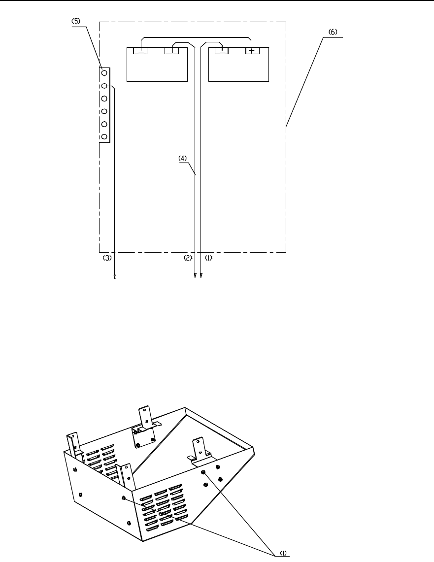
Installation Manual
iSiteC ODU3601C CDMA Soft Base Station Chapter 2 Installing Cabinet Hardware
2-45
To the UPS
To the iSite Auxiliary
Facility Box
1) UPS with power cable (negative cable) 2) UPS with power cable (positive cable) 3) Grounding cable
4) Battery cable 5) PGND bar in the battery box 6) Battery box
Figure 2-45 Internal connection of the IABB (without UPS)
9) Secure the support of the sun-shading cover with M6%12 assembling bolts, as
shown in Figure 2-46.
1) M6%12 assembling bolt
Figure 2-46 Installing sun-shading cover
10) Install the sun-shading cover onto the box, as shown in Figure 2-47.
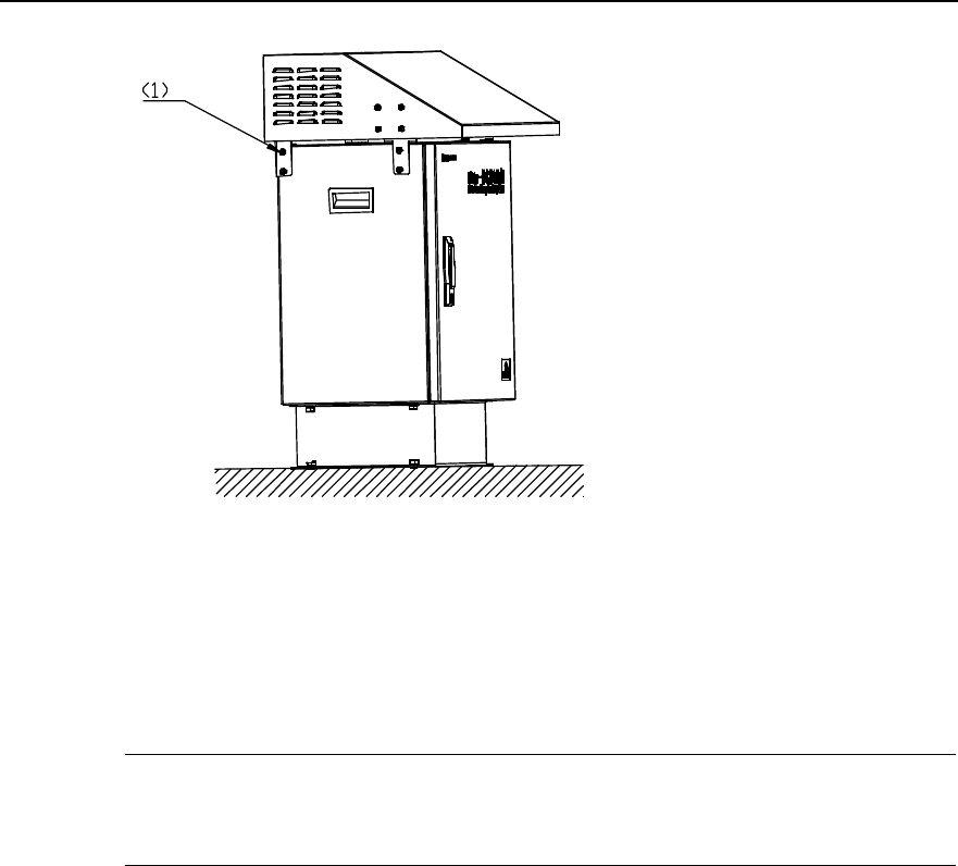
Installation Manual
iSiteC ODU3601C CDMA Soft Base Station Chapter 2 Installing Cabinet Hardware
2-46
1) M6%12 assembling bolt
Figure 2-47 Fixing the sun-shading cover
Installing the box on steel platform:
&
Note:
Procedure to install the box on steel platform is similar to that on concrete floor.
1) Install the fixing support onto the battery box via 4 M12%20 assembling bolts, as
shown in Figure 2-42.
2) Place the box on the platform and mark positions on the platform for all 4
connection holes in the fixing support.
3) Drill holes using a percussion drill with the bit of v16. After the drilling, remove the
dust inside and outside the holes with a vacuum cleaner, and then check the
distance among holes. Whenever big errors occur, the relevant holes must be
relocated and drilled again.

Installation Manual
iSiteC ODU3601C CDMA Soft Base Station Chapter 2 Installing Cabinet Hardware
2-47
Caution:
1) Hold the drilling bit vertical to the platform during drilling. Hold tight the drillstock with two hands to keep
it in the right direction, as vibrations may lead to damaged platform and the hole not straight.
2) The hole depth should be the length of the expansion bolt sleeve plus the drill bit. The hole depths of
respective holes should be consistent. Before measuring the hole depth, remove the dust inside the hole
and measure the hole depth. Remove the dust with a vacuum cleaner before drilling.
3) If the platform is too hard and smooth to settle the drill bit, punch a pit with a chisel to help positioning the
hole.
4) Unfix the spring washer, nut and plain washer. Put the expansion bolt into the hole
and knock directly on the bolt with a hammer (such as nail hammer) until the bolt is
completely driven into the hole. Then, put the nut on the bolt and tighten it until the
bolt is expanded slightly so as to avoid it getting loose.
Caution:
The hole depth should be big enough (55mm~65mm); otherwise, the expansion bolts cannot be
completely driven into the holes, which may affect the reliability of the box.
5) Put in turn spring washers and plain washers onto the 4 M12%60 bolts, and pull the
bolts through the holes at the bottom of the support then through the holes made
at the bottom of the platform. Put washers and nuts onto the bolt, and tighten the
nuts reliably with a spanner.
6) Method to install the sun-shading cover is the same as that mentioned in
"Installing the box on concrete floor".
2.5 Installing Cables
During the installation of ODU3601C major equipment, the cables (excluding feeders)
at the ODU3601C side have been distributed. Following is to introduce the cable
connections between major equipment and auxiliary equipment, and those among
auxiliary equipment in terms of varied networking modes. The installation of feeders is
covered in Chapter 3.

Installation Manual
iSiteC ODU3601C CDMA Soft Base Station Chapter 2 Installing Cabinet Hardware
2-48
2.5.1 Cable Connection Requirements
I. For power cables
1) Gists for indoor installation
l Power cables should not be cross-connected or in parallel with signal cables.
l Cables distributed on the wall must be protected by PVC cabling trough, which
should be fixed on the wall with wall fixing clips. And cables should be distributed
horizontally and straight. Even if turns are unavoidable, the minimum angle at
each turn should not be smaller than 120°.
l Power cables should be labeled after the connection. For the appearance and
contents of the power cable label, refer to "Appendix F Engineering Labels for
Cables ".
2) Gists for outdoor installation
l It is strongly prohibited to tie AC power cable on the iron objects and then lead it
into ODU3601C. Instead, the cable should be first connected to porcelain insulator,
then to ODU3601C.
l Power cables distributed along the iron object and pole must be protected by
currgated tubes, as well as the transmission cables. The tubes should be fixed
with black ties. Cables should be distributed as horizontally and straight as
possible. If turns of cables are unavoidable, the turns should be be made smoothly
via circular arcs.
II. For grounding cables
As the requirements for grounding cable connections are comparatively complicated.
Following is to describe them in terms of varied installation modes.
1) Installing ODU3601C on tower
l The grounding of ODU3601C system and tower lightning protection system must
share the same grounding body.
l When the ODU3601C is close to the transformer for power distribution (straight
distance less than 30m), the counterpoise of the ODU3601C system should be
connected to that of the transformer and form a unified counterpoise.
l When an independent grounding busbar is adopted for the ODU3601C, it should
be installed on the tower directly without any insulation processing. The grounding
busbar of the ODU3601C should have the dedicated grounding downlead made of
40%4mm hot-gavanlizing flat steel. The PGND bar should be connected or welded
to the grounding downlead via 35mm2 yellow-green plastic insulation copper core
wire. The downlead should not be insulated from the tower body.
2) Installing ODU3601C on poles
l The PGND of ODU3601C system should share the same grounding body with the
lightning protection grounding of poles.

Installation Manual
iSiteC ODU3601C CDMA Soft Base Station Chapter 2 Installing Cabinet Hardware
2-49
l When the ODU3601C is close to the transformer for power distribution (straight
distance less than 30m), the counterpoise of the ODU3601C system should be
connected to that of the transformer so as to form a unified counterpoise.
l The overlapped parts of the metal fixing beam (between the two poles) and the
downlead of the lightning arrester should be soldered together reliably. Various
equipment is installed on the metal holding support between fixing beams (the
support is soldered on the beams). The mechnical parts of all equipment should
contact the metal holding support directly without any insulation processing.
Full-length welding should be adopted here, instead of dot welding, as the latter is
unreliable.
l The overlapped parts between the metal fixing parts of the platform and the
downleads of the two lightning arresters should be reliably welded together. Or,
instead, a 40%4mm hot-galvanizing flat steel should be installed on the platform.
The two ends of the steel should be welded to the bench and the middle part of the
steel to the downleads of arresters. If the platform and the downleads of arresters
have not be welded together when the concrete pole is set up, connect them via
35mm2 yellow-green protection grounding cable and the grounding clip that
connects the flat steel to the OT. Full-length welding should be adopted here,
instead of dot welding, as the latter is unreliable.
l Cabling ladder should be installed and fixed via metal fixing beam between two
poles for antenna feeders. Good electric connection should be achieved between
the cabling ladder and the fixing beam. Meanwhile, the overlapped parts of the
fixing beam and the downlead of the lightning arrester should be welded together.
l ODU3601C grounding busbar should be installed directly on metal holding
support or platform without any insulation processing. A dedicated grounding
downlead (made of 40%4mm hot-galvanizing flat steel) should be prepared for the
grounding busbar. ODU3601C grounding busbar should be connected to the
grounding downlead via 35mm2 yellow-green plastic insulation copper wire or be
welded with it. And the downlead should not be insulated from various metal parts
between the two poles.
l Installing ODU3601C on metal mast of building-top
l The PGND of ODU3601C system should share the same grounding body with the
lightning protection grounding of the metal mast on building-top.
l If the building containing the ODU3601C is close (straight distance less than 30m)
to the transformer for power distribution, the counterpoise of the building should be
connected to that of the transformer and form a unified counterpoise.
l ODU3601C grounding busbar should be installed together with the ODU3601C
directly on the metal mast without any insulation processing. At the same time, a
grounding cable should be led from the metal mast to the ODU3601C grounding
busbar, be fixed via bolts or be welded onto the metal mast. It should be made of
yellow-green plastic insulation copper wire with the core diameter not less than
16mm2. Or, instead, a piece of 40%4mm hot-galvanizing flat steel should be

Installation Manual
iSiteC ODU3601C CDMA Soft Base Station Chapter 2 Installing Cabinet Hardware
2-50
welded onto the mast and the wire hole should be reserved on the other end of the
steel, so as to connect grounding cable to the ODU3601C grounding busbar.
l If grounding bar or grounding point is available in the building-top or inside the
building (e.g. the PGND bar of the communication euipment room), the downlead
of the ODU3601C grounding busbar should be connected directly to the grounding
bar available on building-top or inside the building. The grounding downlead
should be made of yellow-green plastic insulation copper wire with the core
diameter not less than 35mm2.
l If no grounding point is available inside the building, the downlead of the
ODU3601C grounding busbar should be led down to the building bottom and
connected to the counterpoise of the building. The downlead should be made of
40%4mm hot-galvanizing flat steel or yellow-green plastic insulation copper wire
with the core diameter not less than 35mm2.
3) Installing ODU3601C indoors
l If the equipment room is close (straight distance less than 30m) to the transformer
for power distribution, the counterpoise of the equipment room should be
connected to that of the transformer so as to form a unified counterpoise.
l If PGND bar is available inside the equipment room, the grounding busbar of the
ODU3601C system should be connected via PGND cable to the grounding bar of
the equipment room directly. The grounding cable should be made of 35mm2
yellow-green plastic insulation copper wire.
l If PGND bar is available in other rooms (e.g. communication equipment room in
the building) instead of the equipment room, the downlead of the ODU3601C
grounding busbar should be connected to the grounding bar in such room. The
grounding downlead should be made of yellow-green plastic insulation copper
wire with the core diameter not less than 35mm2. If no groundign point is available
in the whole building, the downlead may be led down to the bottom of the building
then to the counterpoise of the building. The grounding downlead should be made
of yellow-green plastic insulation copper wire with the core diameter not less than
35mm2.
2.5.2 Networking of AC Lightning Protection Box
I. Plan without the IABB
Figure 2-48 shows the connection between the ODU3601C and an independent AC
lightning protection box.
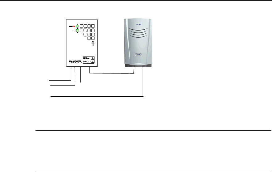
Installation Manual
iSiteC ODU3601C CDMA Soft Base Station Chapter 2 Installing Cabinet Hardware
2-51
220VAC
ODU3601C 220VAC input cable
ODU3601C
AC lightning protection box
A pair of fiber cables or E1 cable
Grounding cable
Figure 2-48 Networking of AC lightning protection box (20kA, without the IABB)
&
Note:
In terms of its discharging currents, the AC lightning protection box can be classified into three types: 20kA,
40kA and 100kA. All boxes mentioned in the chapter are of 20kA.
Three cables are used for the external connection of the AC lightning protection box:
1) External power supply input cable
It is a twin-core cable (L, N). When AC power is led into the box via this cable, the live
wire is connected to the "L" end and the neutral wire to the "N" end.
The cable is provided by user and the ends of the cable can be distinguished via a
multimeter, i.e. the one with lower voltage is "N" end, and the higher one is "L" end.
2) Cable connecting the box to the ODU3601C
It is a complete three-core cable (L, N, and PE). The port at ODU3601C side is a round
waterproof connector which has been installed during the instllation of major equipment.
The output interface of the lightning protection box is an air switch. When connecting
this cable, directly take off the cover of the cable and insert the copper-core wire into
the switch.
In terms of its appearance, if the cable comprises three wires, black one, white one and
yellow-green one, the black is L end, the white is N end, and the last one is PGND wire.
If it is made of coffee, blue, and yellow-green wires, the coffee wire is the L, the blue
wire is the N, and the last one is PGND wire.
Figure 2-49 shows the connection.
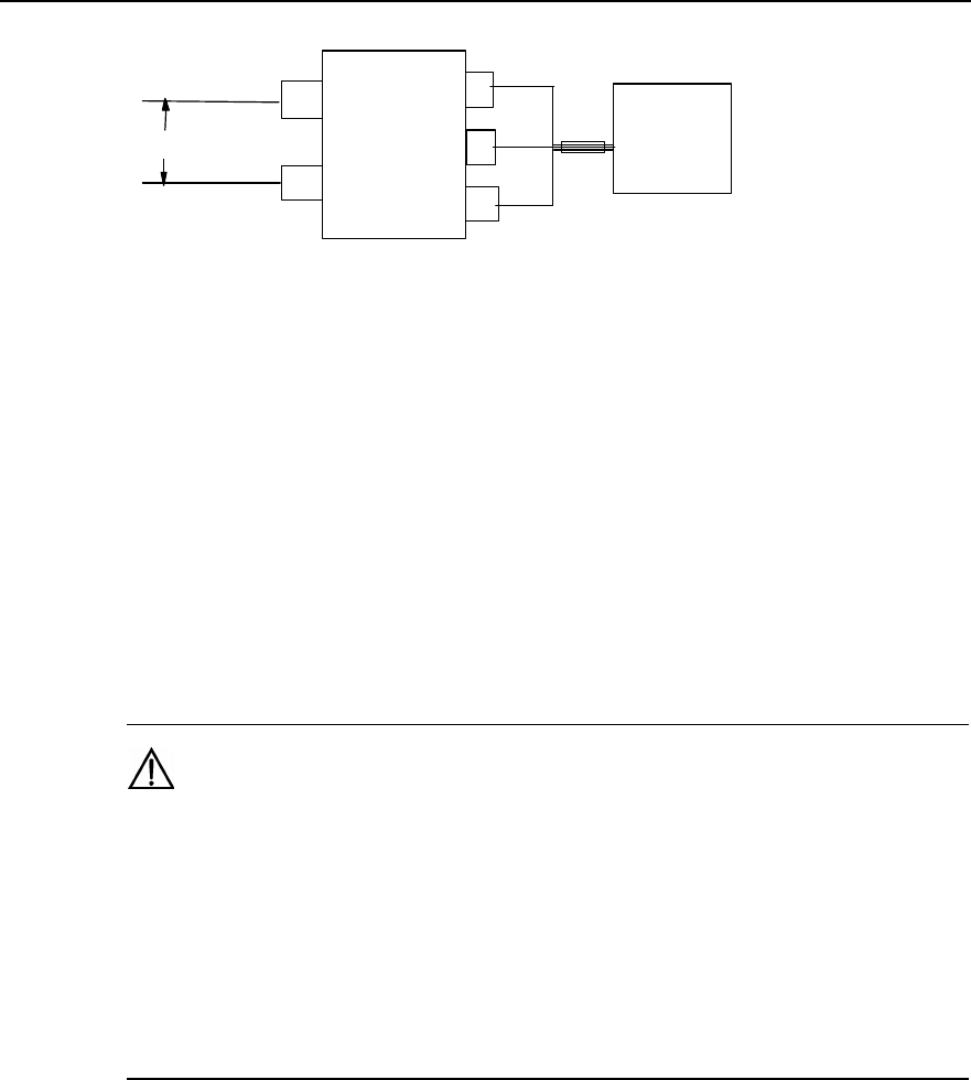
Installation Manual
iSiteC ODU3601C CDMA Soft Base Station Chapter 2 Installing Cabinet Hardware
2-52
LL
N
N
PE
220VAC ODU3601C
AC lightning
protection box
Figure 2-49 Cable connection of AC lightning protection box networking (without UPS)
3) Grounding cable of the AC lightning protection box
Inside the box, there is a grounding bar. If the AC power cable carries PGND cable (PE
wire), the PGND cable should be grounded together with the PGND of the ODU3601C
system. The PE wire should be connected directly to the grounding bar of the box.
AC lightning protection box should have a PGND, and the PGND cable should be made
of yellow-green plastic insulation copper wire with the core diameter not less than
16mm2. The length of the PGND cable connecting to the ODU3601C grounding busbar
should be less than 1m.
Caution:
1) Generally, the only power cable provided by Huawei together with the ODU3601C is 3m. Users are
required to prepare the extra cable if it is not long enough.
2) The external AC power cable to the ODU3601C should be connected to the AC lightning protection box.
It is not allowed to connect the external power cable to the terminal for power distribution in the IAFB first,
then to the AC lightning protection box.
3) Above principles for cable connection are also applicable to the IAFB (with AC lightning protection box
built-in).
II. Plan with the IABB
Figure 2-50 shows the connection in this networking mode.
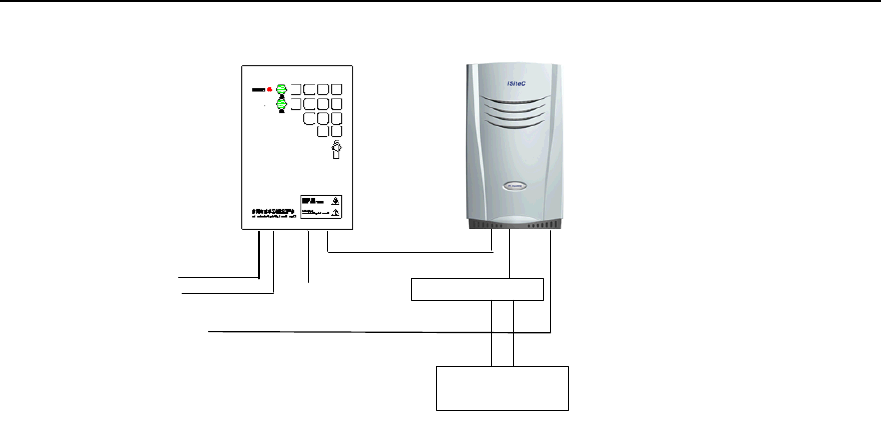
Installation Manual
iSiteC ODU3601C CDMA Soft Base Station Chapter 2 Installing Cabinet Hardware
2-53
220VAC
ODU3601C 220VAC Input cable
ODU3601C
AC lightning protection box
A pair of fiber cables or E1 cable
Conversion connector
+24V GND
Grounding cable
IABB
Figure 2-50 Networking of AC lightning protection box (20kA, with the IABB)
In this plan, the cable connection of AC lightning protection box is completely the same
as that of the IABB. Following is to describe the cable connection between the IABB
and the ODU3601C.
1) Cable connection between IABB and ODU3601C
Two cables are led out from the IABB. One is of +24V and red, and the other is of GND
and black. Two cables are connected to the DC power cable of the ODU3601C through
a commutator. The +24V cable is interconnected to the red one of the ODU3601C DC
power cable through the red plug of the connector; and the black GND cable is
interconnected to the black one of the ODU3601C power cable through the black pulg
of the commutator. After their interconnections, two types of tapes should be used for
the waterproof of the connections. The detailed processing is available in Section 2.3.6.
2) Grounding of the IABB
The battery box is generally installed on the platform. In this case, the metal shell of the
box should be grounded, and the PGND wire should be connected to the ODU3601C
grounding busbar from the PGND terminal. The wire should be made of yellow-green
plastic insulation copper wire with the core diameter not less than 16mm2. The batteries
inside the box should not be grounded.
2.5.3 Networking of IAFB
I. Plan with backup power supply equipment
Figure 2-51 shows the connection between the IAFB and the ODU3601C in the
ODU3601C networking (without UPS and the IABB).
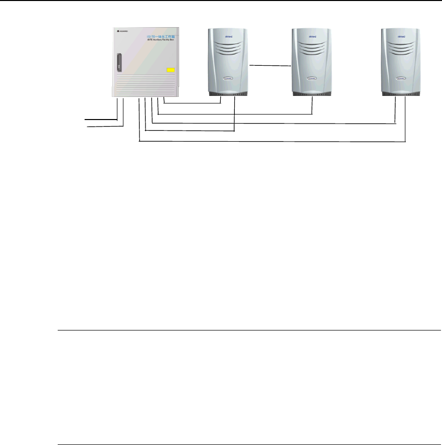
Installation Manual
iSiteC ODU3601C CDMA Soft Base Station Chapter 2 Installing Cabinet Hardware
2-54
220VAC
ODU3601C 220VAC Input cable
ODU3601C 220VAC Input cable
ODU3601C 220VAC Input cable
ODU3601C ODU3601C ODU3601C
IAFB
The 1st pair of fiber cables or E1 cable
Cascading
The 2nd pair of fiber cables or E1 cable
Figure 2-51 Networking between ODU3601C and IAFB (without backup power supply equipment)
220V AC power is led into the air switch of the IAFB, then to the ODU3601C. One IAFB
can supply power for up to 3 ODU3601Cs at the same time.
Please connect the relevant cables correctly according to the labels on them, the
correspondence shown in Figure 2-52 and Figure 2-53, and the correspondence
between labels and cables shown in Table 2-3.
&
Note:
1) Figure 2-53 shows the front view of cable connection on DDF shown in Figure 2-52.
2) The PGND cables of ODU3601C and other equipment in the system should all be connected to the
grounding bar on the shell of the IAFB. And a PGND cable should be led from the grounding bar on the
IAFB shell and connected to the grounding downlead of the counterpoise. This grounding cable should be
made of yellow-green plastic insulation copper wire with the core diameter not less than 35mm2.
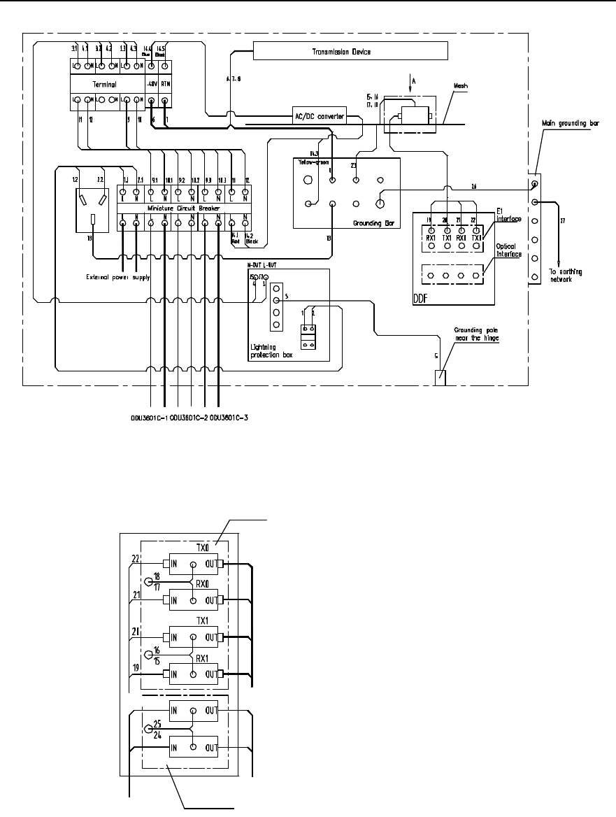
Installation Manual
iSiteC ODU3601C CDMA Soft Base Station Chapter 2 Installing Cabinet Hardware
2-55
Figure 2-52 Cable distribution of IAFB networking (without UPS)
E1 lightning
arrester
To DDF To transmission
device
To HDSL device
HDSL lightning arresterInput signal cable
Direction A
Figure 2-53 Trunk cable distribution of IAFB networking (without UPS)

Installation Manual
iSiteC ODU3601C CDMA Soft Base Station Chapter 2 Installing Cabinet Hardware
2-56
Table 2-3 Description of cable distribution in IAFB networking (without UPS)
Cable No. Code Name Quanti
ty
1 DKBA04041975WX Power cable connecting air switch to AC lightning protection
box 1
2 DKBA04041976WX Power cable connecting air switch to AC lightning protection
box 1
3 DKBA04041977WX Power cable connecting AC lightning protection box to wiring
terminal 1
4 DKBA04041978WX Power cable connecting AC lightning protection box to wiring
terminal 1
5 DKBA04041979WX Grounding cable for AC lightning protection box 1
6 DKBA04041980WX Power cable connecting transmission equipment to wiring
terminal 1
7 DKBA04041981WX Power cable connecting transmission equipment to wiring
terminal 1
8 DKBA04041982WX Power cable connecting transmission equipment to wiring
terminal 1
9 DKBA04041984WX Power cable from wiring terminal to bipolar air switch 1
10 DKBA04041985WX Power cable from wiring terminal to bipolar air switch 1
11 DKBA04041986WX Power cable connecting wiring terminal to air switch (without
UPS) 1
12 DKBA04041987WX Power cable connecting wiring terminal to air switch (without
UPS) 1
13 DKBA04200197ZP Grounding cable for AC socket 1
15~18 DKBA04200199ZP Grounding cable for signal lightning arrester 4
19~22 DKBA4.851.2527MX E1 interface cable 4
23 DKBA04040980WX PGND cable 1
26 DKBA04041983WX Internal grounding cable for IAFB 1
27 DKBA04040300WX PGND power cable 1
II. Plan with backup power supply equipment
If the mains supply at the ODU3601C side is interrupted, the UPS backup power supply
system will continue to power the ODU3601C and all its auxiliary equipment, instead.
Figure 2-54 shows how the IAFB connects to the ODU3601C and UPS.
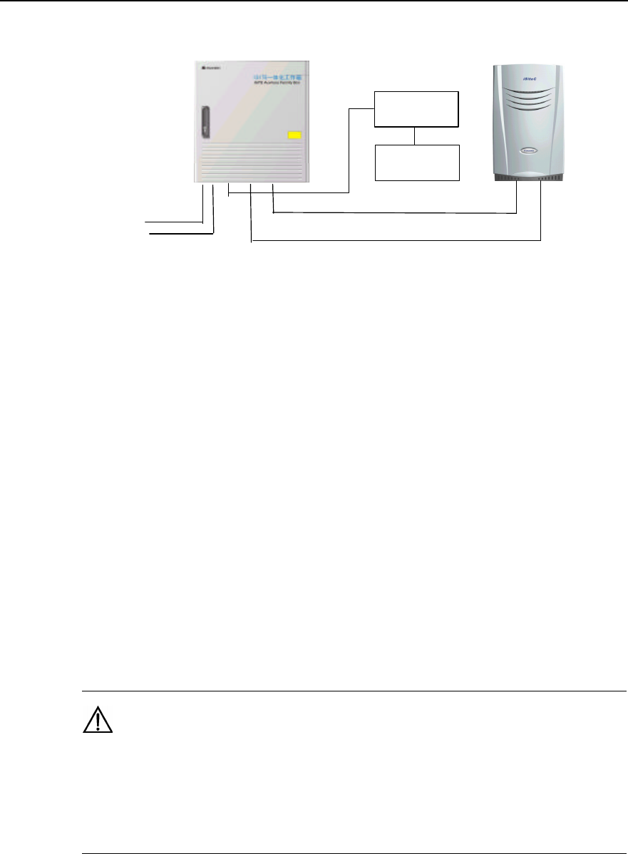
Installation Manual
iSiteC ODU3601C CDMA Soft Base Station Chapter 2 Installing Cabinet Hardware
2-57
220VAC
ODU3601C 220VAC Input cable
ODU3601C
IAFB
The 1st pair of fiber cables or E1 cable
UPS
IABB
Figure 2-54 Networking containing ODU3601C and IAFB (with ODU3601C backup power supply
equipment)
Following are their detailed cable connections:
1) Cable connection between UPS and IABB
UPS connects to the IABB via two cables, i.e. one is negative cable and the other is
positive cable. Each cable has one of its ends equipped with a four-core plug to
connect to the UPS. On plugs, labels are attached to tell the positive end (+) and
negative end (-). The other end needs to be prepared at site: There are two big OT
connectors and heat-shrink tubes; cut the available cable (10m long) between the UPS
and the IABB into the piece (with proper length according to the site conditions), then
make the OT connector with a crimping piler and then connect the terminal to the
connector at the battery. This cable should be led through the inlet at the bottom of the
battery box and in. The cable length should be minimized for the sake of lightning
protection.
Caution:
1) The cables must be connected to the UPS and the battery box correctly with their polarities in
correspondence with those at the plugs of the UPS and the battery box. Any incorrect connection will result
in the damage of the UPS and batteries.
2) Relabel the cut cable correctly at once if the original label has been damaged when cutting the cable.
2) Cable connection among IAFB, ODU3601C and UPS
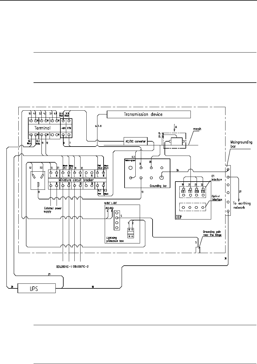
Installation Manual
iSiteC ODU3601C CDMA Soft Base Station Chapter 2 Installing Cabinet Hardware
2-58
It is required to connect cables among IAFB, ODU3601C and UPS according to labels
on them, the correspondence shown in Figure 2-55 and Figure 2-56, and the
correspondence between labels and cables described in Table 2-4.
&
Note:
Figure 2-56 shows the front view of the cable connection on DDF shown in Figure 2-55.
Figure 2-55 Cable distribution in IAFB networking
&
Note:
In Figure 2-55, the power of ODU3601C 1 is protected by UPS, i.e. when its power is interrupted, the UPS
will instead supply it with power. However, the ODU3601C 2 is not protected.
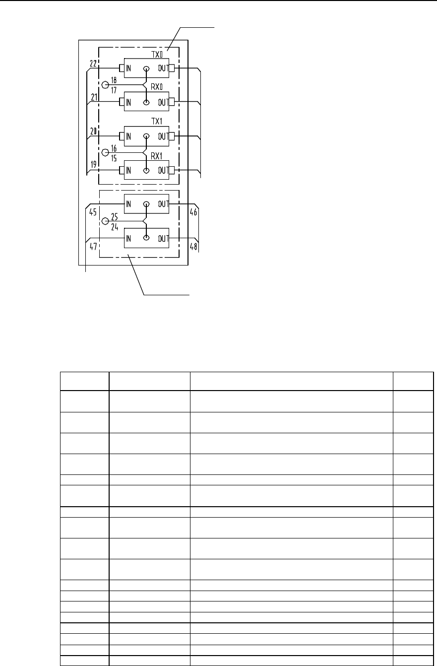
Installation Manual
iSiteC ODU3601C CDMA Soft Base Station Chapter 2 Installing Cabinet Hardware
2-59
E1 lightning arrester
To DDF
A direction
To transmission
device
To HDSL
device
HDSL lightning
arrester
Input signal cable
Figure 2-56 Trunk cable distribution in IAFB networking (1 ODU3601C with UPS)
Table 2-4 Description of cable distribution in IAFB netwroking (1 ODU3601C with UPS)
Cable No. Code Name Quantity
1 DKBA04041975WX Power cable connecting air switch to AC lightning protection
box 1
2 DKBA04041976WX Power cable connecting air switch to AC lightning protection
box 1
3 DKBA04041977WX Power cable connecting AC lightning protection box to
wiring terminal 1
4 DKBA04041978WX Power cable connecting AC lightning protection box to
wiring terminal 1
5 DKBA04041979WX Grounding cable for AC lightning protection box 1
6 DKBA04041980WX Power cable connecting transmission equipment to wiring
terminal 1
7 DKBA04041981WX Power cable from transmission equipment to wiring terminal 1
8 DKBA04041982WX Power cable connecting transmission equipment to wiring
terminal 1
11 DKBA04041986WX Power cable connecting wiring terminal to air switch (without
UPS) 1
12 DKBA04041987WX Power cable connecting wiring terminal to air switch (without
UPS) 1
13 DKBA04200197ZP Grounding cable for AC socket 1
15~18 DKBA04200199ZP Grounding cable for signal lightning arrester 4
19~22 DKBA4.851.2527MX E1 interface cable 4
23 DKBA04040980WX PGND cable 1
26 DKBA04041983WX Internal grounding cable for IAFB 1
27, 30 DKBA04040300WX PGND power cable 2
28 DKBA04041990WX UPS power cable 1
29 DKBA04041991WX UPS POWER CABLE 1
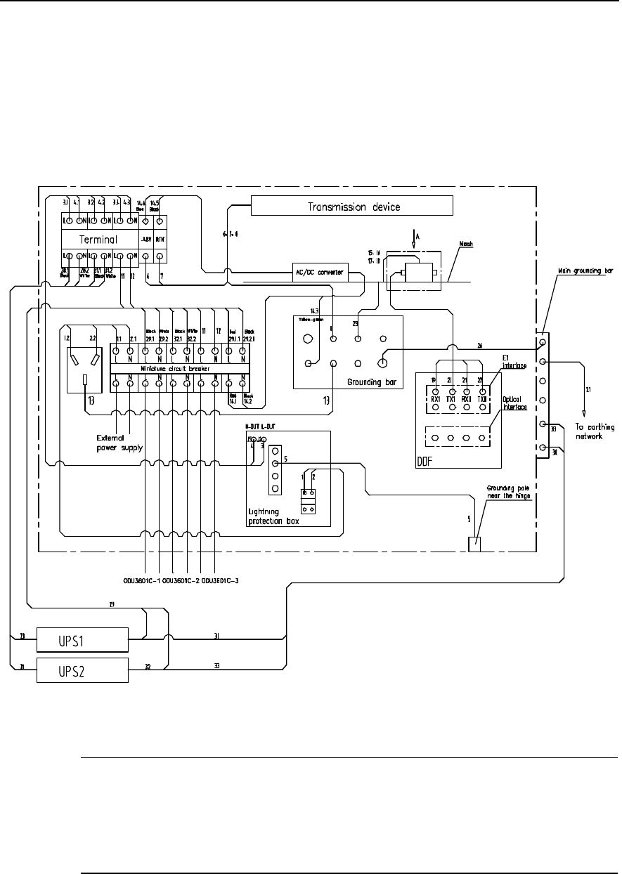
Installation Manual
iSiteC ODU3601C CDMA Soft Base Station Chapter 2 Installing Cabinet Hardware
2-60
An IAFB can connect up to 3 ODU3601Cs. Following is to describe the cable
connections in terms of the varied number of ODU3601C connected to IAFB.
3) IAFB networking (2 ODU3601Cs with UPS)
It is required to connect cables sent to the site according to labels on them, the
connection correspondence shown in Figure 2-57 and Figure 2-58, and the
correspondence between labels and cables described in Table 2-5.
Figure 2-57 Cable distribution in IAFB networking (2 ODU3601Cs with UPS)
&
Note:
In Figure 2-57, if the AC power supply of ODU3601C 1 and ODU3601C 2 is interrupted, UPS will power
them, instead. However, when the AC power of ODU3601C 3 is interrupted, UPS will not power it with AC
power.
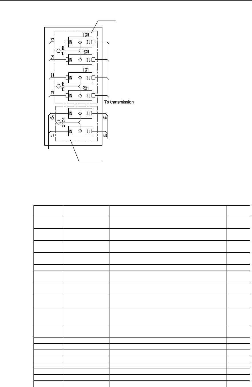
Installation Manual
iSiteC ODU3601C CDMA Soft Base Station Chapter 2 Installing Cabinet Hardware
2-61
E1 lightning
arrester
device
To HDSL device
HDSL lightning
arrester
Input signal cable
To DDF
A direction
Figure 2-58 Trunk cable distribution in IAFB networking (2 ODU3601Cs with UPS)
Table 2-5 Description of cable distribution in IAFB networking (2 ODU3601Cs with UPS)
Cable No. Code Name Quantity
1 DKBA04041975WX Power cable connecting air switch to AC lightning protection
box 1
2 DKBA04041976WX Power cable connecting air switch to AC lightning protection
box 1
3 DKBA04041977WX Power cable connecting AC lightning protection box to
wiring terminal 1
4 DKBA04041978WX Power cable connecting AC lightning protection box to
wiring terminal 1
5 DKBA04041979WX Grounding cable for AC lightning protection box 1
6 DKBA04041980WX Power cable connecting transmission equipment to wiring
terminal 1
7 DKBA04041981WX Power cable connecting transmission equipment to wiring
terminal 1
8 DKBA04041982WX Power cable between transmission equipment and wiring
terminal 1
11 DKBA04041986WX Power cable connecting wiring terminal to air switch (without
UPS)
1
12 DKBA04041987WX Power cable connecting wiring terminal to air switch (without
UPS) 1
13 DKBA04200197ZP Grounding cable for AC socket 1
15~18 DKBA04200199ZP Grounding cable for signal lightning arrester 4
19~22 DKBA4.851.2527MX E1 interface cable 4
23 DKBA04040980WX PGND cable 1
26 DKBA04041983WX Internal grounding cable of IAFB 1
27, 30, 33 DKBA04040300WX PGND power cable 3
28, 31, 32 DKBA04041990WX UPS power cable 3
29 DKBA04041991WX UPS power cable 1
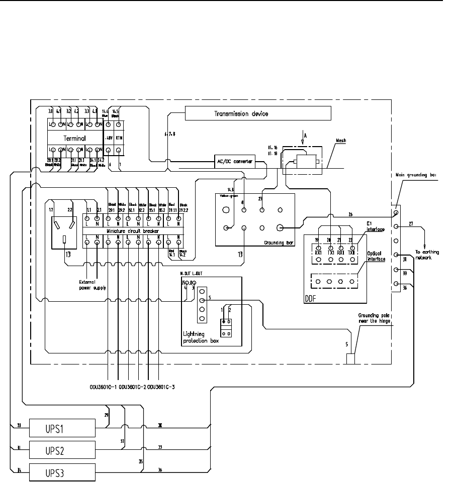
Installation Manual
iSiteC ODU3601C CDMA Soft Base Station Chapter 2 Installing Cabinet Hardware
2-62
4) IAFB networking (3 ODU3601Cs with UPS)
It is required to connect cables sent to the site according to labels on them, the
connection correspondence shown in Figure 2-59 and Figure 2-60, and the
correspondence between labels and cables described in Table 2-6.
Figure 2-59 Cable distribution in IAFB networking (3 ODU3601Cs with UPS)
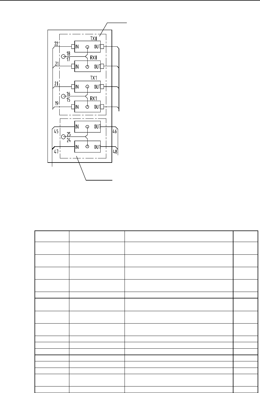
Installation Manual
iSiteC ODU3601C CDMA Soft Base Station Chapter 2 Installing Cabinet Hardware
2-63
A direction
E1 lightning
arrester
To transmission
device
To HDSL device
HDSL lightning arrester
Input signal cable
To DDF
Figure 2-60 Trunk cable distribution in IAFB networking (3 ODU3601Cs with UPS)
Table 2-6 Description of cable distribution in IAFB networking (3 ODU3601Cs with UPS)
Cable No. Code Name Quantity
1 DKBA04041975WX Power cable between air switch and AC lightning
protection box 1
2 DKBA04041976WX Power cable between air switch and AC lightning
protection box 1
3 DKBA04041977WX Power cable between AC lightning protection box and
wiring terminal 1
4 DKBA04041978WX Power cable between AC lightning protection box and
wiring terminal 1
5 DKBA04041979WX Grounding cable for AC lightning protection box 1
6 DKBA04041980WX Power cable connecting transmission equipment to
wiring terminal 1
7 DKBA04041981WX Power cable connecting transmission equipment to
wiring terminal 1
8 DKBA04041982WX Power cables connecting transmission equipment to
wiring terminal 1
13 DKBA04200197ZP Grounding cable for AC socket 1
15~18 DKBA04200199ZP Grounding cable for signal lightning arrester 4
19~22 DKBA4.851.2527MX E1 interface cable 4
23 DKBA04040980WX PGND cable 1
26 DKBA04041983WX Internal grounding cable of IAFB 1
27, 30, 33, 36 DKBA04040300WX PGND power cable 4
28, 31, 32, 34,
35 DKBA04041990WX UPS power cable 5
29 DKBA04041991WX UPS power cable 1
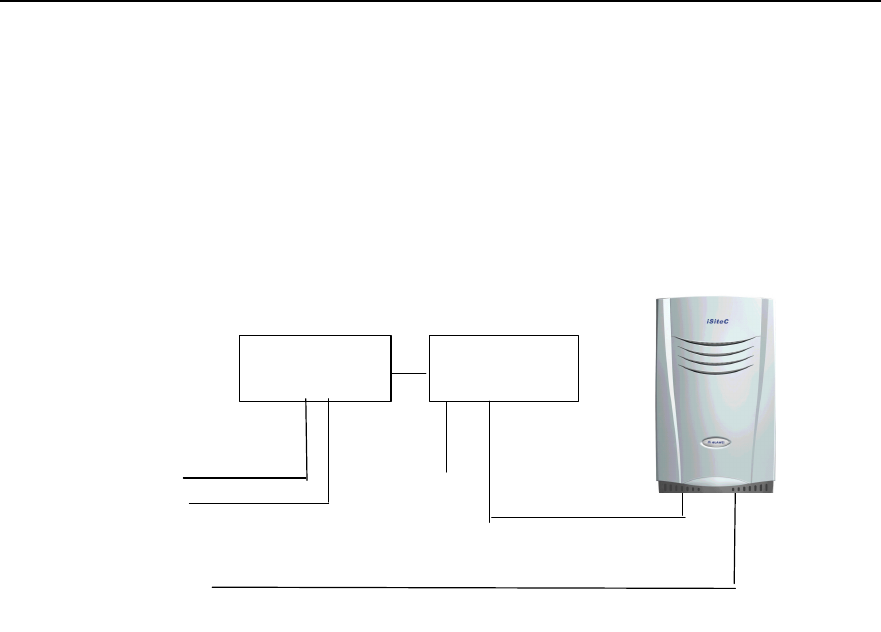
Installation Manual
iSiteC ODU3601C CDMA Soft Base Station Chapter 2 Installing Cabinet Hardware
2-64
2.5.4 Networking of Inverter
This networking mode is applied to sites where -48V power supply is available. Figure
2-61 shows the specific networking.
-48V
ODU3601C 220VAC Input cable
ODU3601C
Inverter
A pair of fiber cables or E1 cable
DC lightning
protection box
Grounding cable
Figure 2-61 Inverter networking
It is required that the metal shell of the inverter be grounded, and the PGND cable of
the step-up transformer be connected to ODU3601C grounding busbar directly. The
PGND cable of the inverter should be made of yellow-green plasitc insulation copper
wire with the core diameter not less than 16mm2.
For detailed connections of inverter cables, please refer to the relevant contents in
product manuals.

Installation Manual
iSiteC ODU3601C CDMA Soft Base Station Chapter 3 Installing RF Antenna and Feeder System
3-1
Chapter 3 Installing RF Antenna and Feeder
System
As a soft BTS, the antenna and feeder part of the ODU3601C only comprises RF
antenna and feeder part, excluding satellite synchronization antenna and feeder part.
This is the difference between an ODU3601C BTS and other BTSs (such as cBTS3612,
cBTS3606, and cBTS3601C). The RF antenna and feeder system of ODU3601C
consists of antenna, feeder, jumper and feeder grounding clip, etc.
3.1 Installation Flow
According to different installations of the ODU3601C major equipment, the installation
of the antenna and feeder system differs. The installation flow of the antenna and
feeder system is shown in Figure 3-1.
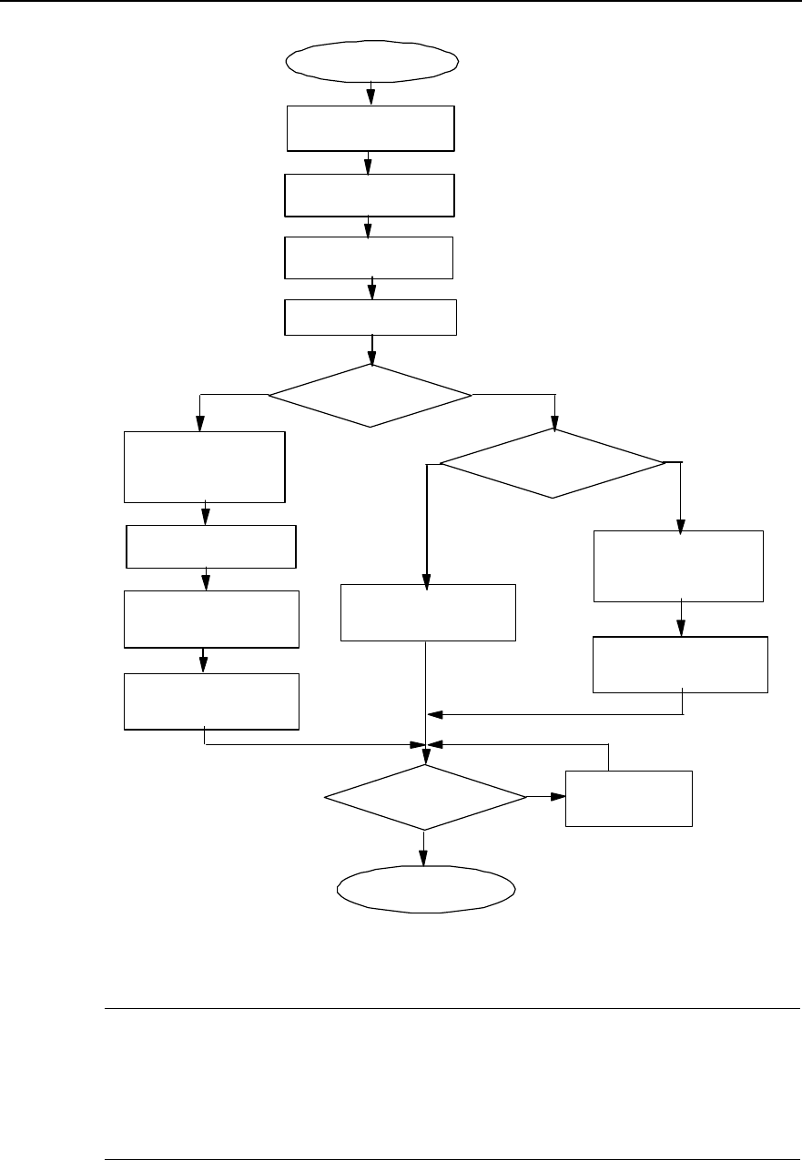
Installation Manual
iSiteC ODU3601C CDMA Soft Base Station Chapter 3 Installing RF Antenna and Feeder System
3-2
Install feeder, then
connect antenna with
feeder through jumper, and
get feeder grounded.
Install sealing window
for feeder.
Lead feeder indoor and
apply sealing window
upon feeder.
The installation
is done.
Do antenna and feeder pass
the testing?
NLocate the problem
and take actions.
Y
Assemble antenna
Install copper busbar
Install antenna support
Install antenna
Start to install
Connect feeder with
mini-MS
Want to connect mini-MS
with antenna through
jumper?
Y
Connect mini-MS with
antenna
Install feeder, then
connect antenna with
feeder through jumper, and
get feeder grounded.
Connect mini-
MS with feeder
N
Select the
installation mode
Indoor
installation Outdoor
installation
Figure 3-1 Installation flow of antenna and feeder system
&
Note:
The installation of antenna and feeder system is exemplified by the indoor installation of ODU3601C. For
the antenna and feeder installation in case of ODU3601C outdoor installation, please refer to the
installation of the antenna and feeder system of ODU3601C indoor installation.
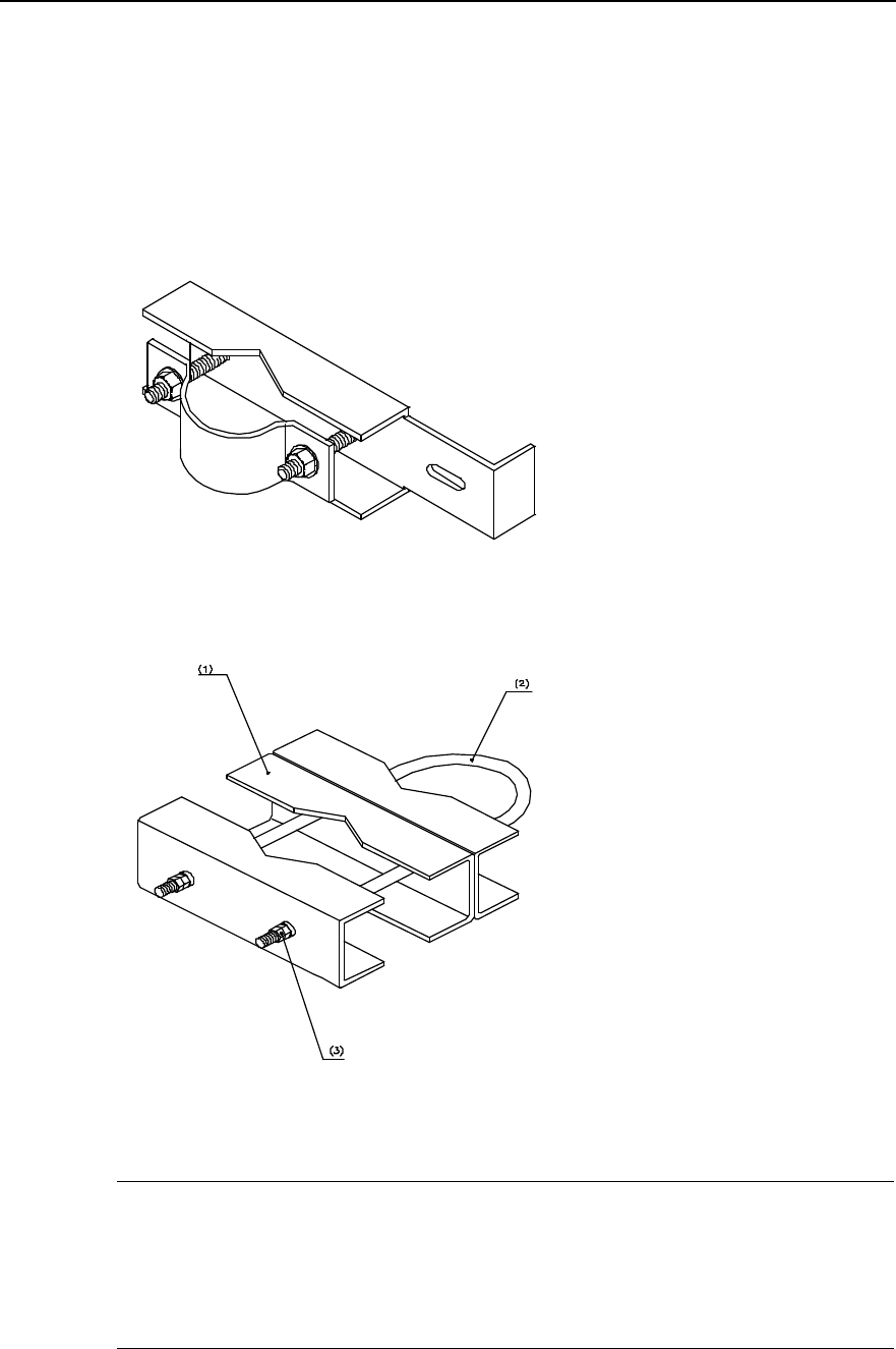
Installation Manual
iSiteC ODU3601C CDMA Soft Base Station Chapter 3 Installing RF Antenna and Feeder System
3-3
3.2 Installing Antenna Accessories
3.2.1 Installing Omni Antenna Accessories
Accessories used to assemble the omni antenna are antenna fixing clip and jumper.
The omni antenna fixing clip is shown in Figure 3-2 and Figure 3-3.
Figure 3-2 Omni antenna fixing clip (1)
(1) Omni antenna joint (2) M12%580 U-bolts (3) Nut M12
Figure 3-3 Omni antenna fixing clip (2)
&
Note:
There are various types of fixing clips for the omni antenna, including the two shown in Figure 3-2 and
Figure 3-3 for reference. In practical installation, the fixing clips should be applied according to the actual
situations. The following takes the antenna fixing clip as shown in Figure 3-2 as an example.
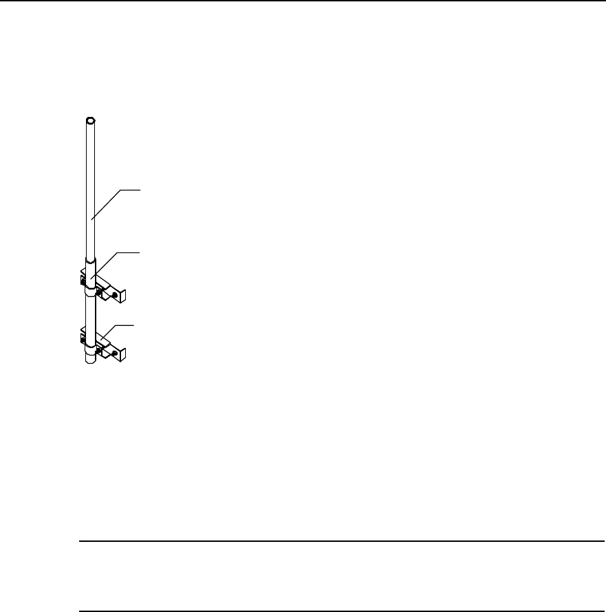
Installation Manual
iSiteC ODU3601C CDMA Soft Base Station Chapter 3 Installing RF Antenna and Feeder System
3-4
The installation procedure of accessories is as follows:
1) Assemble the two fixing clips of the omni antenna with the part contacting the
antenna fastened so as to reduce the work on the tower or the building-top, as
shown in Figure 3-4.
(1)
(2)
(3)
(1)Omni antenna (2) Antenna jacket (3) Omni antenna fixing clip
Figure 3-4 Fixing omni antenna
2) Connect the jumper connector to the antenna connector and fasten it.
3) Perform waterproof and sealing treatment to the joint between the antenna and
the jumper. Please refer to Section 2.3.6 for the waterproof treatment.
&
Note:
Steps 2) and 3) can be completed on the tower or the building-top.
3.2.2 Installing Directional Antenna Accessories
Accessories used to assemble the directional antenna are antenna fixing clip (as
shown in Figure 3-5), tilt angle adjustment device (as shown in Figure 3-6), and jumper.
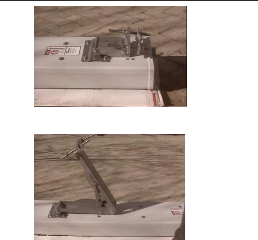
Installation Manual
iSiteC ODU3601C CDMA Soft Base Station Chapter 3 Installing RF Antenna and Feeder System
3-5
Figure 3-5 Directional antenna fixing clip
Figure 3-6 Directional antenna tilt angle adjustment device
The installation procedure of accessories is as follows:
1) First, determine the two fixed adjusting points on the top and bottom of the
antenna according to the label on the back of the antenna. The point on the top of
the antenna is for adjusting the pitch angle, and the point on the bottom for fixing
the antenna and its support.
2) Mount each accessory to its position according to the assembly diagram provided
by the vendor. All the accessories must be furnished with spring washers and plain
washers.
3) Jumper connection: Take off the jacket at the lower part of the antenna. Then
connect the jumper connector and the antenna connector and fasten them.
4) Perform waterproof treatment to the connector (the same method as that to the
connector between omni antenna and jumper).
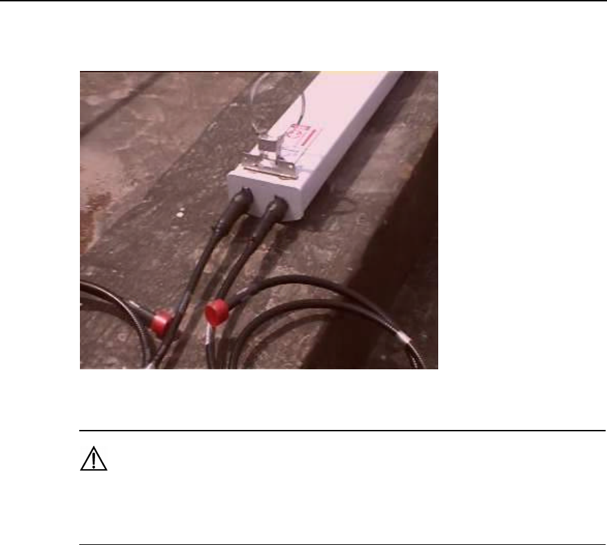
Installation Manual
iSiteC ODU3601C CDMA Soft Base Station Chapter 3 Installing RF Antenna and Feeder System
3-6
Figure 3-7 shows the connection between the directional antenna and jumper, and the
jumper connector after treatment.
Figure 3-7 Connection between directional antenna and jumper and jumper connector after treatment
Caution:
Antenna fixing clip and pitch angle adjustment device must be furnished with spring washers and plain
washers in correct installation sequence.
3.3 Installing Grounding Bar
Grounding copper bar is used to connect the PGND and working ground of the cabinet.
It should be installed both indoor and outdoor. In indoor installation, it is usually
mounted on the wall near the ODU3601C; while in outdoor installation, it is usually
mounted near the ODU3601C, yet its specific position is determined according to the
actual situation. The structure of grounding copper bar is shown in Figure 3-8.
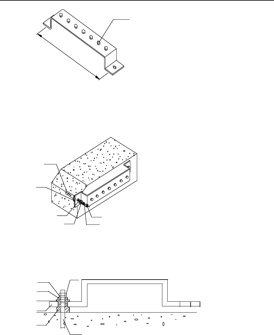
Installation Manual
iSiteC ODU3601C CDMA Soft Base Station Chapter 3 Installing RF Antenna and Feeder System
3-7
(1)
330mm
(1) M8 bolt
Figure 3-8 Structure of the grounding copper bar
The installation is shown in Figure 3-9 and Figure 3-10.
(1)
(2)
(3)
(4)
(5)
(6)
(1) Nut M12 (2) Spring washer v12 (3) Large plain washer
(4) Insulation washer 1 (5) Insulation washer 2 (6) M12%80 exploded expansion bolt
Figure 3-9 Installing the grounding copper bar
(1)
(2)
(3)
(4)
(6)
(7) 墙
(5)
(1) Nut M12 (2) Spring washer v12 (3) Large plain washer (4) Insulation washer 1
(5) Indoor grounding copper bar (6) Insulation washer 2 (7) M12%80 exploded expansion bolt
Figure 3-10 Sectional view of grounding copper bar installation
The insulation washer is shown in Figure 3-11.
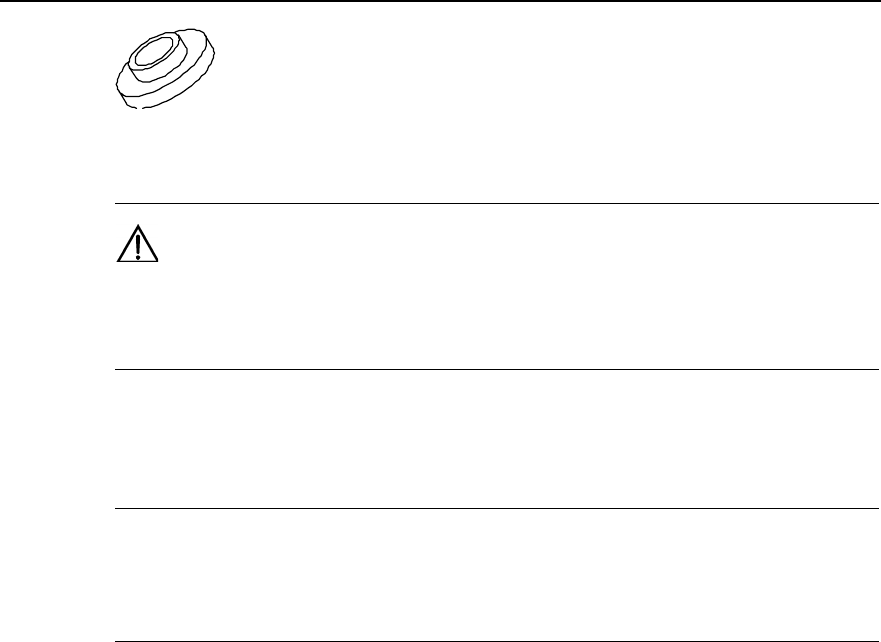
Installation Manual
iSiteC ODU3601C CDMA Soft Base Station Chapter 3 Installing RF Antenna and Feeder System
3-8
Figure 3-11 Insulation washer
Caution:
Insulation washer should be furnished when the expansion bolt is installed. So the grounding copper bar is
insulated from the wall.
3.4 Installing Antenna Support
&
Note:
In non-turnkey project, the user should prepare the antenna support when preparing the environment.
Huawei is responsible for antenna support installation only in turnkey project.
There are a number of structures and types of antenna support. The following gives two
installation methods for antenna support as examples, namely, installing antenna
support on tower platform and on building-top.
3.4.1 Installing Support on Tower Platform
I. Antenna support structure
Figure 3-12 shows the antenna support installed on tower.
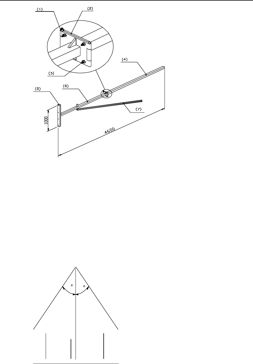
Installation Manual
iSiteC ODU3601C CDMA Soft Base Station Chapter 3 Installing RF Antenna and Feeder System
3-9
(1) M12%220 bolt (2) Joint soleplate (3) M12%45 bolt (4) Expansion arm
(5) Fixing arm (6) Whirling arm (7) Reinforcing arm
Figure 3-12 Structure of antenna support installed on tower
II. Installation requirements
1) Installation plane of the antenna support should be vertical to the horizontal plane.
2) Tower lightning arrester mast should be installed separately with the height
satisfying lightning protection requirements of all antennae. When the support
extends out of the tower platform, it should be ensured that the antenna is within
the protection range formed by 30° pitch angle of the lightning arrester apex, as
shown in Figure 3-13.
30 30
RX TX RX
Figure 3-13 Installing the lightning arrester
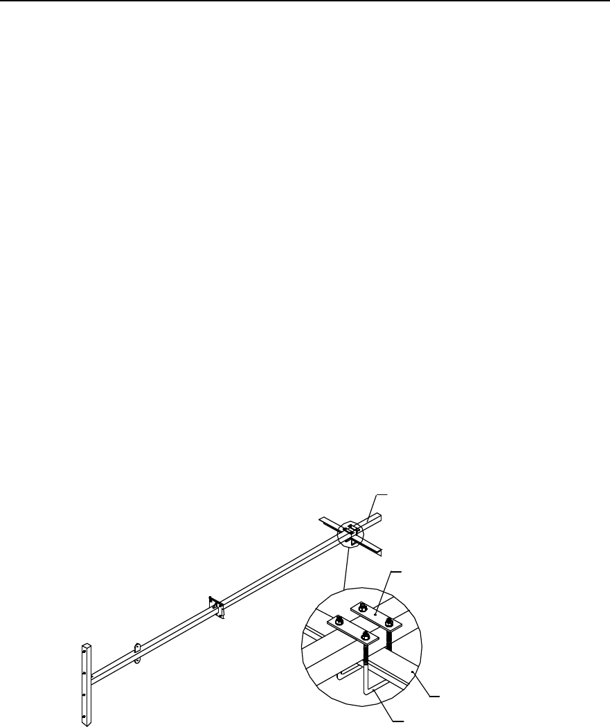
Installation Manual
iSiteC ODU3601C CDMA Soft Base Station Chapter 3 Installing RF Antenna and Feeder System
3-10
3) Make sure that the installation direction of the antenna support would not influence
the receiving (RX)/transmitting (TX) performance and direction adjusting of the
antenna.
4) If necessary, take suspension measures to avoid distortion of the antenna support
as it will be in use for a long time.
5) Whirling arm should be reinforced by reinforcing arm. The length of expansion arm
and whirling arm may be determined according to the onsite situation. The fracture
should be soldered with cover plate to avoid leaking water.
6) All the soldered parts should be secure enough without dry joint and open solder
point. The surface of the support should be covered by anti-rust silvery paint.
Better choose zinc-coated steel for the support.
III. Installation procedure
1) Install a fast pulley on the tower top. Use one or two lifting ropes to hoist the
support to the tower platform via the fixed pulley. Besides, a rope is needed to
control the upward direction of the support;
2) Determine the installation position of the antenna support on building-top
according to the antenna and feeder installation diagram in the engineering design
drawing.
3) Fix the support on the tower with a U-shape fixing clip, as shown in Figure 3-14.
4) Connect the tower platform guardrail and joint soleplate with M12%45 bolt.
(1)
(2)
(3
)
(4)
(1) Expansion arm (2) Connecting arm (3) Tower beam (4) U-bolt
Figure 3-14 Installing the antenna support on tower
Installing Support on Building-top
IV. Antenna support structure
Figure 3-15 illustrates the antenna support installed on building-top.
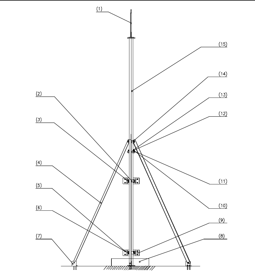
Installation Manual
iSiteC ODU3601C CDMA Soft Base Station Chapter 3 Installing RF Antenna and Feeder System
3-11
(1) Antenna lightning arrester (2) 180° joint (3) V-joint (4) Reinforcing arm
(5) Expansion M12%120 bolt (6) Washer v12 (7) Anchor (8) Covered with
concrete
(9) Mounting plate (soldered) (10) Spring washer v10 (11) Washer v10 (12) Nut M10
(13) M10%45 bolt (14) 120° joint (15) Mainstay support of
the antenna
Figure 3-15 Structure of antenna support installed on building-top
V. Installing requirements
1) The installation position of joint for reinforcing arm should not affect the adjustment
of antenna direction and pitch angle.
2) Antenna support must be vertical to the horizontal plane.
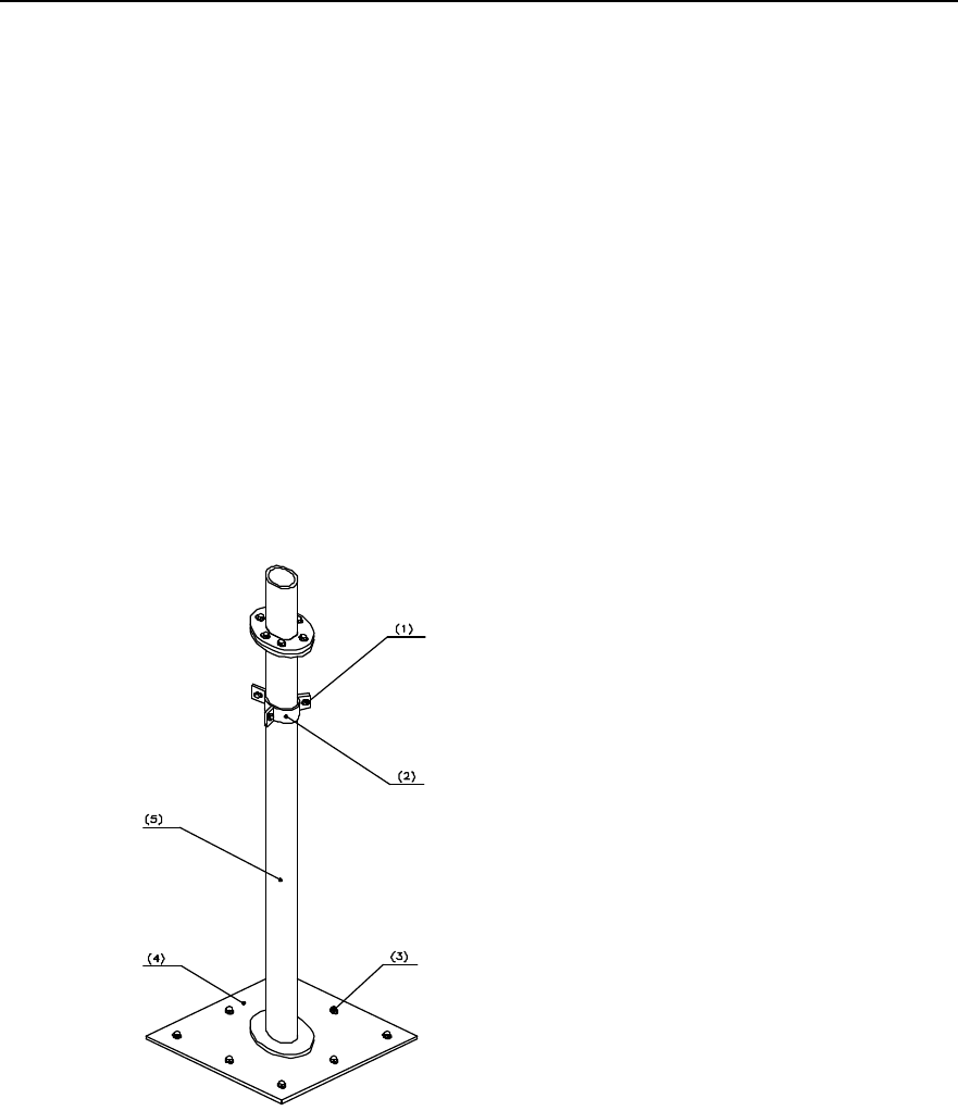
Installation Manual
iSiteC ODU3601C CDMA Soft Base Station Chapter 3 Installing RF Antenna and Feeder System
3-12
3) Antenna support on building-top must be equipped with lightning arrester, and the
support should be connected to the building lightning-protection network.
4) The surface of the support and all the soldered parts should be covered by
anti-rust paint. All the soldered parts should be secure enough without dry joint
and open solder point.
VI. Installing the support on building-top without parapet
1) Hoist the support to the building-top.
2) Determine the installation position of the antenna support on building-top
according to the antenna and feeder installation diagram in the engineering design
drawing.
3) Solder the lightning arrester on the mainstay support of the antenna (with the axes
aligned).
4) As shown in Figure 3-16, fix the base of the antenna on the building-top vertically
with eight M10%45 expansion bolts.
(1) Hexagonal M10%50 bolt (2) Joint for reinforcing
arm (3) M10%50 exploded
expansion bolt
(4) Plastic foot for antenna mainstay support (5) Mainstay support of
the antenna
Figure 3-16 Installing the antenna support base
5) Mainstay support needs to be reinforced with reinforcing arm whose length is
determined according to that of the mainstay support. As shown in Figure 3-17,
the reinforcing arm is connected to the mainstay support through its joint. Connect
the anchors to the reinforcing arm and fix the anchors of each reinforcing arm on
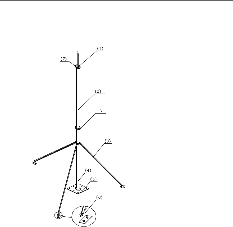
Installation Manual
iSiteC ODU3601C CDMA Soft Base Station Chapter 3 Installing RF Antenna and Feeder System
3-13
the building-top floor with two M10%45 expansion bolts. Make sure the connection
of the reinforcing arms will not be twisted.
6) As shown in Figure 3-17, connect mainstay support 2 with mainstay support 1
tightly with six M10%80 bolts.
8
(1) Antenna lightning arrester (2) Mainstay support 2 (3) Reinforcing arm (4) Mainstay support 1
(5) Plastic root for support (6) Anchor of reinforcing
arm (7) Soldered parts (8) M10%80 bolt
Figure 3-17 Installing the antenna support
7) There are such cases that the building-top antenna support is not soldered with
outdoor cabling rack; or soldered but the cabling rack is not connected with the
lightning-protection network of the building. In this case, connect the base of the
antenna support to the lightning-protection network of the building with a
lightning-protection connecting bar (the lightning-protection connecting bar is the
installation parts for outdoor cabling rack).
8) Cover all the soldered parts and the support base with anti-rust paint.
9) Base of the building-top antenna support, anchors of the reinforcing arm and the
expansion bolts connected with the floor should all be covered with concrete for
protection.
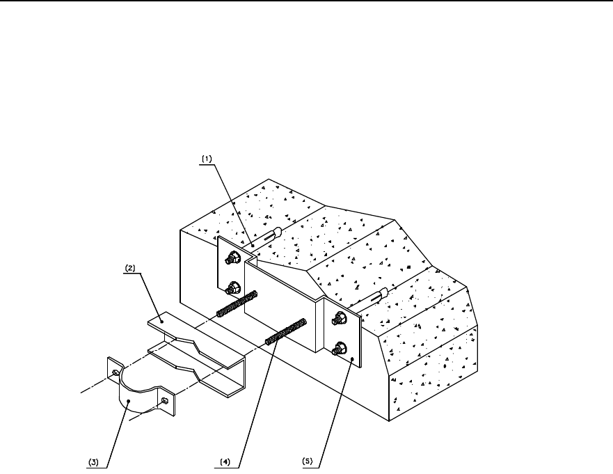
Installation Manual
iSiteC ODU3601C CDMA Soft Base Station Chapter 3 Installing RF Antenna and Feeder System
3-14
VII. Installing the support on building-top with parapet
If there is parapet around the building-top, and it is inconvenient to install the support on
the building-top, just mount the support on the parapet. Figure 3-18 illustrates the
antenna support fixing clip mounted on the parapet.
(1) Expansion M 12%120 bolt (2) V-joint (3) 180° joint
(4) M12×140 bolt (5) Mounting plate
Figure 3-18 Fixing clip of antenna support installed on parapet
In the case the parapet is not shorter than 1200mm, fix the two fixing points of the
support on the parapet with expansion bolts, as shown in Figure 3-19.
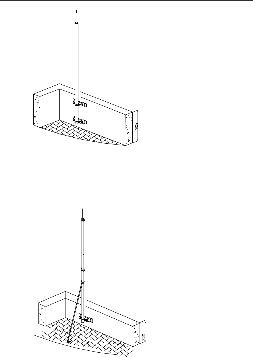
Installation Manual
iSiteC ODU3601C CDMA Soft Base Station Chapter 3 Installing RF Antenna and Feeder System
3-15
Figure 3-19 Antenna support fixed on parapet (with parapet not shorter than 1200mm)
In the case the parapet is shorter than 1200mm, fix one fixing point of the mainstay
support to the parapet with expansion bolt, and the other fixing point to the building, as
shown in Figure 3-20.
小
于
Figure 3-20 Antenna support fixed on parapet (with parapet shorter than 1200MM)
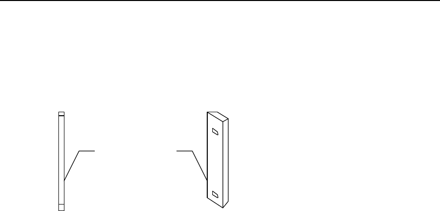
Installation Manual
iSiteC ODU3601C CDMA Soft Base Station Chapter 3 Installing RF Antenna and Feeder System
3-16
3.5 Installing Antenna
3.5.1 Antenna Facade
The façade of omni antenna and directional antenna is shown in Figure 3-21.
(1)
(2)
(1) Omni antenna (2) Directional antenna
Figure 3-21 Antennae
3.5.2 Hoisting Antenna
Tie a knot at both ends of the antenna with a rope. Persons both on the tower and down
the tower cooperate to hoist the antenna to its position. The persons down the tower
should strain on the rope so as to avoid damage to the antenna due to clashing
between the antenna and the tower body or the building.
3.5.3 Installing Omni Antenna
Installation of the omni antenna on the tower platform is shown in Figure 3-22.
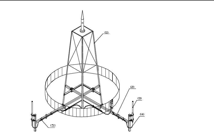
Installation Manual
iSiteC ODU3601C CDMA Soft Base Station Chapter 3 Installing RF Antenna and Feeder System
3-17
(1) Tower (2) Tower-top antenna support (3) Omni antenna
(4) Jumper waterproof elbow (5) Cable tie
Figure 3-22 Installing the omni antenna on tower platform
I. Installation requirements
l When installing the omni antenna on the tower, make sure the antenna is in the
protection range of lightning arrester on the tower. The distance between the omni
antenna and the tower body should be left at least 1.5m.
l The antenna axis should be vertical to the horizontal plane with error less than !1°.
l The TX and RX antenna of omni antenna can be installed on one antenna support,
or be separately installed. The specified installation position should be determined
according to the engineering design drawing.
II. Installation procedure
1) Make the feeding point of the antenna facing down and the jacket near the
mainstay support. The top of the jacket should be on the same level or a little bit
higher than the top of the support.
2) As shown in Figure 3-23, secure the antenna fixing clip and the mainstay support
properly to ensure its load bearing and wind resistibility. It should not be too tight to
damage the jacket of the antenna.
3) Check whether the antenna axis is vertical to the horizontal plane with angle tester.
If the error is equal to or greater than !1°, adjust the antenna axis and then fasten
it.
4) Make waterproof elbow at the antenna connector.
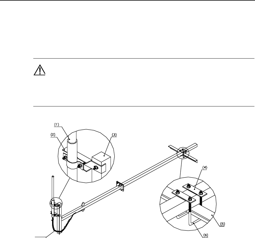
Installation Manual
iSiteC ODU3601C CDMA Soft Base Station Chapter 3 Installing RF Antenna and Feeder System
3-18
5) Route the antenna jumper with natural jumper curves of proper angle. Generally, it
is required that the radius of the curves be 20 times larger than the jumper
diameter and the jumper be bound to the steel rack of the tower along the support
crosspiece with black cable tie.
Caution:
The cable ties should be bound toward the same direction with a margin of 5~10mm to avoid the ties fall off
when temperature changes.
(7)
(1) Antenna (2) Joint (3) Fixing arm (4) Connecting arm
(5) Tower beam (6) U-bolt (7) Jumper waterproof elbow
Figure 3-23 Installing the omni antenna
Installation of omni antenna on building-top support is similar to that on tower side. The
installation is shown in Figure 3-24.
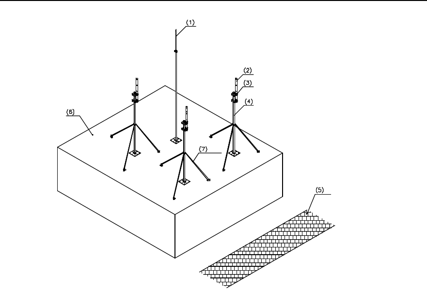
Installation Manual
iSiteC ODU3601C CDMA Soft Base Station Chapter 3 Installing RF Antenna and Feeder System
3-19
(1) Antenna lightning arrester (2) Antenna (3) Omni antenna fixing clip (4) Mainstay support of
antenna
(5) Road surface (6) Building-top (7) Reinforcing arm
Figure 3-24 Installing the omni antenna on building-top support
3.5.4 Installing Directional Antenna
The installation of directional antenna on the tower side is shown in Figure 3-25.
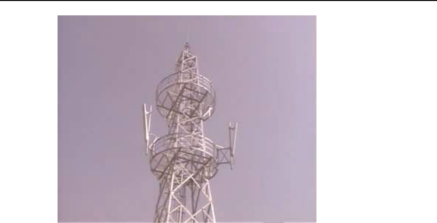
Installation Manual
iSiteC ODU3601C CDMA Soft Base Station Chapter 3 Installing RF Antenna and Feeder System
3-20
Figure 3-25 Installing the directional antenna on the tower side
I. Installation requirements
l When installing the directional antenna on the tower, make sure the antenna is in
the protection range of lightning arrester on the tower. The antenna should stretch
out of the tower body for at least 1m.
l Waterproof elbow must be made to the antenna jumper.
II. Installation procedure
1) Determine the installation direction of the antenna according to the engineering
installation drawing.
2) Fix the antenna onto the main supporting post. The fixing tightness should be right
enough for weight bearing and wind resistance. Looseness may cause loose
connection while too much tension may damage the antenna sheathing;
3) Adjust the antenna azimuth angle: Determine the antenna azimuth angle with a
compass according to the engineering design documents. Normally, Starting from
the north clockwise, the area covered by the first antenna is sector 1. Sector 2 lies
in the clockwise 120° direction and sector 3 in the next clockwise 120° direction, as
shown in Figure 3-26. While adjusting the azimuth, turn the antenna azimuth
slightly till it satisfies the design index value with the azimuth error not greater than
5°.
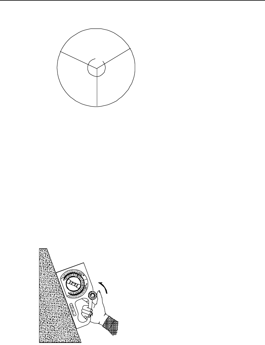
Installation Manual
iSiteC ODU3601C CDMA Soft Base Station Chapter 3 Installing RF Antenna and Feeder System
3-21
Sector 1
North
120˙
120˙
Sector 2
Sector 3
Figure 3-26 Correspondence between directional antenna azimuth and sector
4) Tighten up the lower fixing clip of the antenna till it cannot be moved by hand.
5) Adjust the antenna pitch angle: For the directional antenna whose mounting hole
corresponds to its pitch angle, install it via its mounting hole directly. Make sure the
supporting post of its support is kept strictly perpendicular to the ground during the
installation. Adjust the pitch angles of other antennae in the following way:
l Determine the antenna pitch angle using an inclinometer.
l Turn the antenna slightly and adjust the pitch angle till it satisfies the engineering
design index value. Generally the error of the pitch angle should be Ÿ0.5°.
l Tighten up the upper fixing clip of the antenna till it cannot be moved by hand;
Use the inclinometer in the way as shown in Figure 3-27 and Figure 3-28.
Figure 3-27 Pitch angle of the antenna before being adjusted by the inclinometer
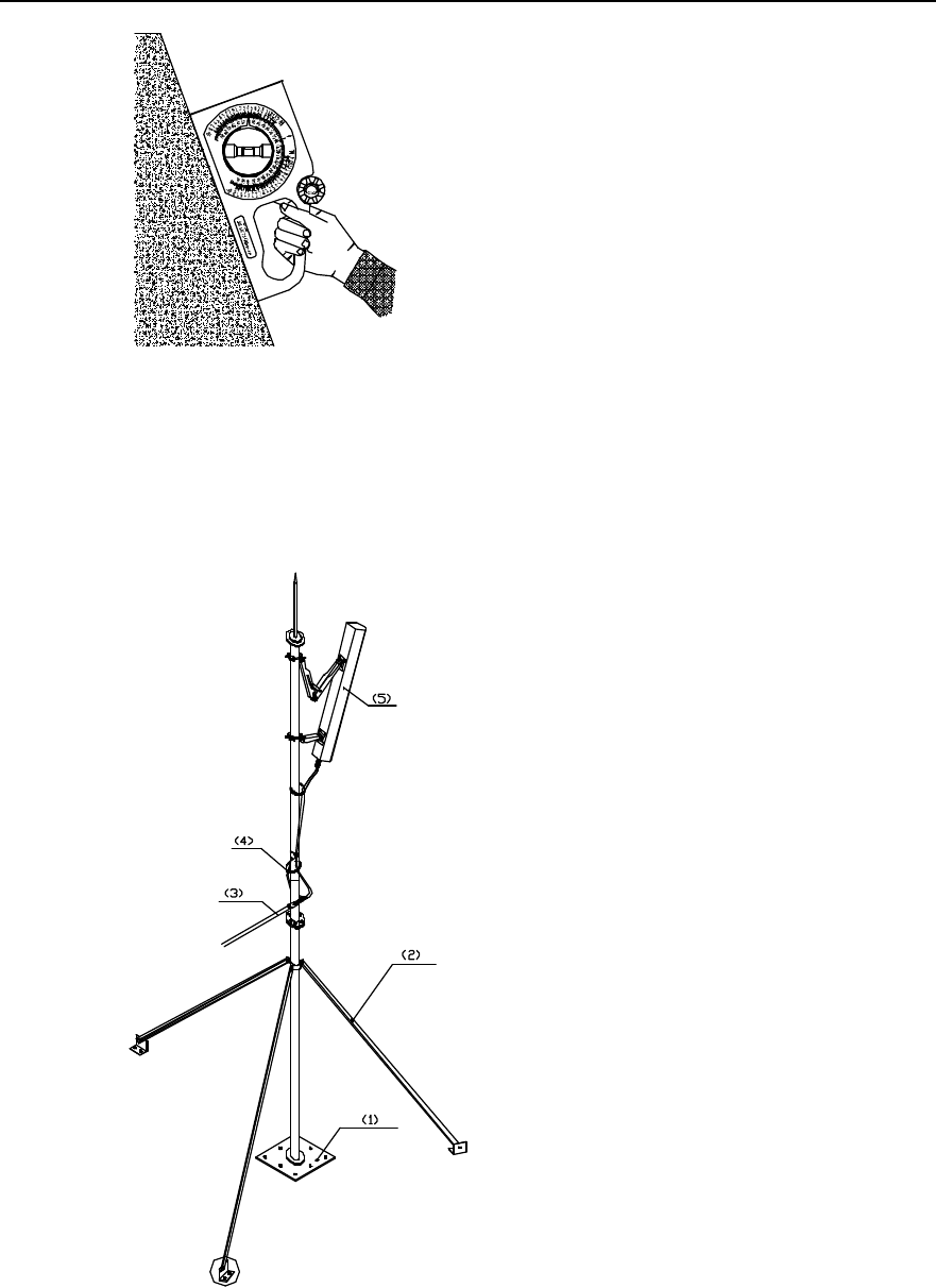
Installation Manual
iSiteC ODU3601C CDMA Soft Base Station Chapter 3 Installing RF Antenna and Feeder System
3-22
Figure 3-28 Pitch angle of the antenna after being adjusted by the inclinometer
6) Make waterproof elbow for the antenna jumper and route the jumper.
Installation of directional antenna on building-top support is similar to that on tower side.
The installation is shown in Figure 3-29 and Figure 3-30.
(1) Plastic root of support (2) Reinforcing arm (3) Feeder
(4) Cable tie (5) Antenna
Figure 3-29 Installing the directional antenna on building-top (without parapet)
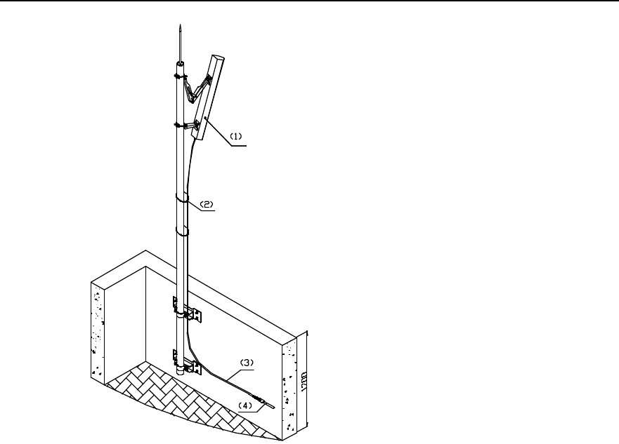
Installation Manual
iSiteC ODU3601C CDMA Soft Base Station Chapter 3 Installing RF Antenna and Feeder System
3-23
(1) Antenna (2) Cable tie (3) Jumper (4) Feeder
Figure 3-30 Installing the directional antenna on building-top support (with parapet not shorter than
1200mm)
3.6 Installing Feeder Window
3.6.1 About Feeder Window
There are two types of feeder windows: 12-hole feeder window and 27-hole feeder
window. The former is used most frequently. Figure 3-31 shows its structure,
dimensions and its connection with the sealing gland. The following gives the
installation method of 12-hole feeder window only.
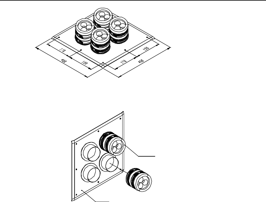
Installation Manual
iSiteC ODU3601C CDMA Soft Base Station Chapter 3 Installing RF Antenna and Feeder System
3-24
(1)
(2)
(1) Sealing packing ring of feeder window (2) Feeder window board
Figure 3-31 Structure and dimensions of feeder window
3.6.2 Installing Feeder Window
Feeder window is usually installed outdoors near and above the cabling rack. If feeders
enter the equipment room from building-top, the feeder window should be installed on
building-top.
Installation procedure is as follows:
1) Determine the indoor installation position for the feeder window according to the
engineering design drawing and the dimensions of the window. Mark the positions
for expansion bolt holes and for feeder window cavity on the wall.
2) As shown in Figure 3-32, drill a square cavity of 250mm % 250mm on the wall, then
drill 8 holes for expansion bolts using a percussion drill.
3) As shown in Figure 3-33, secure the feeder window board with expansion bolts.
When mounting the expansion bolts, note the sequence of spring washer and
plain washer. The sealing gasket and sealing gland may be mounted when leading
the feeder indoor.
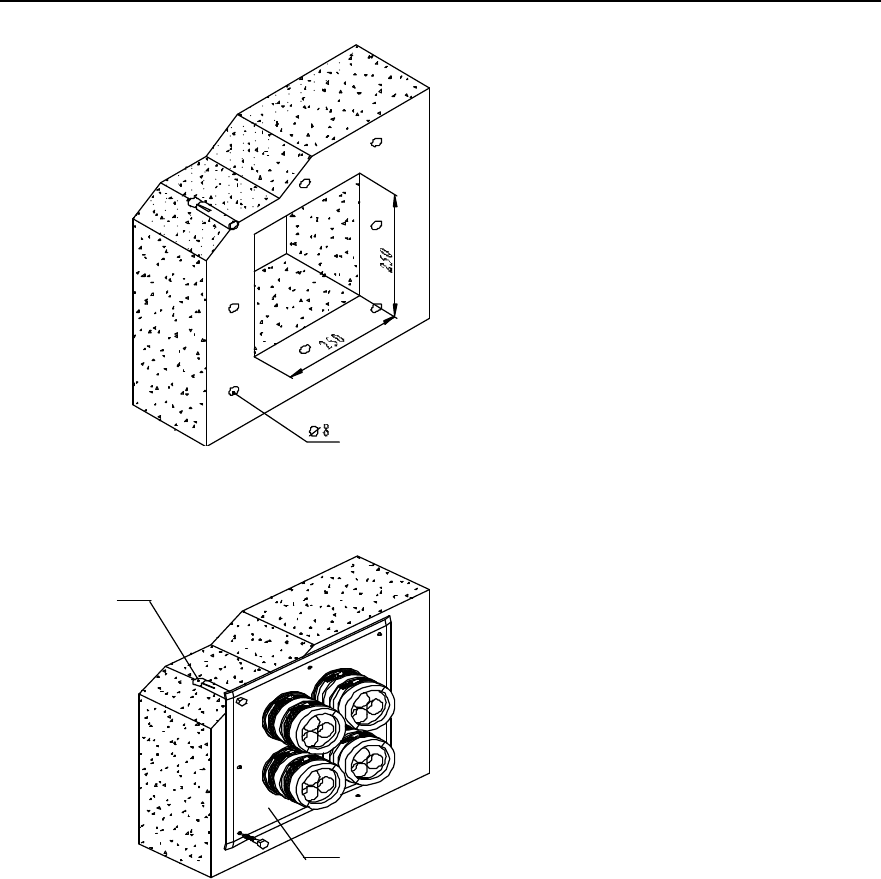
Installation Manual
iSiteC ODU3601C CDMA Soft Base Station Chapter 3 Installing RF Antenna and Feeder System
3-25
Figure 3-32 Mounting holes for feeder window
Indoor
Outdoor
(1)
(2)
(1) M8%80 exploded expansion bolt (2) Feeder window board
Figure 3-33 Installing feeder window
3.7 Installing Feeders
3.7.1 Cutting Feeder
The feeders can be cut prior to or after feeder hoisting.
1) Determine the length of the feeders required in each sector according to the
engineering design drawing;
2) Cut the feeder by the determined length, leaving a margin of 1m~2m. When
cutting the feeder, do not bend it and prevent it from being rolled over or stepped
on by vehicles or pedestrians;
Installation Manual
iSiteC ODU3601C CDMA Soft Base Station Chapter 3 Installing RF Antenna and Feeder System
3-26
3) Attach the corresponding labels to both ends of the feeder after cutting a piece.
3.7.2 Hoisting Feeder
1) Wrap the feeder end in a piece of gunny cloth (or antistatic bag) after the
corresponding connector is completed. Bind the cloth up using a rope or a binding
tape;
2) Knot the lifting rope at the point about 0.4m away from the feeder end and tie
another knot at the point about 4.4m away from the feeder end to prepare for
feeder hoisting, as shown in Figure 3-34.
4000
400
(1)
(2)
(1) Lifting rope (2) Feeder
Figure 3-34 Protection of feeder connector
3) Hoist the feeder to the tower platform. No violent hoisting is allowed so as to avoid
damage to the feeder skin due to possible collision with the building or the tower.
In the meantime, take care of your safety.
4) Fix the upper end of the feeder in a proper position by multiple-point fastening lest
that the feeder fall from the tower. However, it should not be too close to the
antenna, as shown in Figure 3-35. Select 1-for-1 fixing clip or 1-for-3 fixing clip as
is required, as shown in Figure 3-36.
Installation Manual
iSiteC ODU3601C CDMA Soft Base Station Chapter 3 Installing RF Antenna and Feeder System
3-27
Figure 3-35 Feeder upper end fixed on tower
2
(1) (2)
(2)
(1) 1-for-1 fixing clip (2) 1-for-3 fixing clip
Figure 3-36 Feeder fixing clip
5) Connect the jumper between antenna and feeder and perform waterproof and
encapsulation treatment to the connectors. Attach a temporary label at the point
10cm away from the jumper end.
3.7.3 Routing Feeder
Routing procedure:
1) Design the feeder arrangement according to the sector requirement in the
engineering design. Determine the arrangement and lead-in plan. Usually, there is
one row or column of feeders in a sector arranged in the same sequence.
2) Route the feeders according to the planned sequence.
3) Arrange the feeders neatly while fixing them onto the tower or the cabling rack with
fixing clips. Meanwhile, mount the feeder grounding clip and attach feeder labels.
Installation Manual
iSiteC ODU3601C CDMA Soft Base Station Chapter 3 Installing RF Antenna and Feeder System
3-28
3.7.4 Affixing Feeder Labels
I. Label format
Figure 3-37 illustrates the standard nameplate used as both indoor and outdoor labels.
Figure 3-37 RF antenna and feeder label
II. Label position
1) ODU3601C indoor installation mode
Feeder labels can be affixed in three positions, which are (from the top down):
l 0.3m to the outdoor feeder connector;
l Outside the feeder entrance to the feeder window;
l 0.3m to the indoor feeder connector.
2) ODU3601C outdoor installation mode
Feeder labels can be affixed in two positions, which are (from the top down):
l 0.3m to the outdoor feeder connector;
l 0.3m to the front end connecting the ODU3601C.
3.7.5 Grounding Feeders
Installation of feeder grounding clip and routing of feeders are carried out
simultaneously. When grounding the feeders, ground the feeder skin with the lightning
protection grounding clip. The grounding cable led out should be connected to the
Installation Manual
iSiteC ODU3601C CDMA Soft Base Station Chapter 3 Installing RF Antenna and Feeder System
3-29
protection grounding bar directly. The following gives description of feeder grounding
points in different installation modes.
I. ODU3601C outdoor installation mode
l Within the range of 1m~2m under the antenna;
l The front end connecting the ODU3601C.
Caution:
1) When soft jumper is adopted for the feeder and the feeder is not longer than 5m, the shielding covering
of the feeder may be grounded at the front end connecting the ODU3601C.
2) If the feeder is longer than 60m, feeder grounding clips should be applied in the middle of the feeder,
with the clip spacing of 20m.
II. ODU3601C indoor installation with the outdoor feeder longer than 20m
l Within the range of 1m~2m under the antenna;
l Within 1m range of the mast or of where the feeder is led from the tower platform;
l At the outer side of the feeder window where the feeder enters the equipment
room (connecting to outdoor PGND bar).
l Close to the indoor protection grounding bar after it enters the equipment room.
Others:
l If the feeder is longer than 60m, feeder grounding clips should be applied in the
middle of the feeder, with the clip spacing of 20m.
l If the feeder is led into the room after being routed for a stretch of distance on the
building-top, and the distance exceeds 20m, a feeder grounding clip should be
applied on building-top.
l For the feeder that enters the room from the building-top along the wall, if a cabling
rack is used, the cabling rack should also be grounded.
l Feeder grounding cable should be routed toward the ODU3601C antenna and
feeder port along the antenna. The included angle between the feeder grounding
cable and the feeder should not be greater than 15°. The feeder grounding clip
should be directly secured to the steel board on the nearby tower body.
III. ODU3601C indoor installation with the outdoor feeder shorter than 20m
l Within the range of 1m~2m under the antenna;
l At the outer side of the feeder window where the feeder enters the equipment
room (connecting to outdoor PGND bar);
l Close to the indoor PGND bar after it enters the equipment room.
Installation Manual
iSiteC ODU3601C CDMA Soft Base Station Chapter 3 Installing RF Antenna and Feeder System
3-30
Caution:
1) When soft jumper is adopted for the feeder and the feeder is not longer than 10m, the shielding covering
of the coaxial soft jumper may be grounded at two points, i.e., below the antenna and indoor.
2) When soft jumper is adopted for the feeder and the feeder is not longer than 5m, the shielding covering
of the coaxial soft jumper may be grounded at one point indoor.
3.7.6 Leading Feeder into Equipment Room
I. Feeder arrangement principle
l There are 4 big holes in a 12-hole feeder window, and 3 small holes in each big
hole. One feeder can run through a small hole.
l The feeders should be arranged in sequence (i.e. clockwise or counter-clockwise)
in the three small holes of the same big hole.
l The arrangement of feeders in the feeder window should facilitate system
expansion. The original arrangement of feeders should not be changed during
system expansion. It is permitted to add feeders to the feeder window and change
the jumper connection on the cabinet top only.
l The arrangement of feeders in the feeder window should facilitate the routing of
feeders on the cabling rack and the connection of feeders with the cabinet top. The
feeders should be parallel to each other without any cross.
l The length of the feeder entering the feeder window should be 30cm~50cm. If
there is an indoor cabling rack, the feeder can be fixed with feeder clip. If not, the
feeder may be hanged in air.
Caution:
The minimum feeder curving radius should not be less than 20 times of the feeder diameter.
There should be no cross of the feeder when it is routed along the cabling rack and tower cabling ladder.
And there should be no crossing or overlapping of the feeder entering the equipment room. Therefore, it is
required to get an idea of the feeder routing prior to feeder distribution. It is best to draft the actual feeder
routing on paper to avoid rework due to feeder crossing.
II. Procedure
1) Make waterproof elbow for the feeder at the outer side of the feeder window.
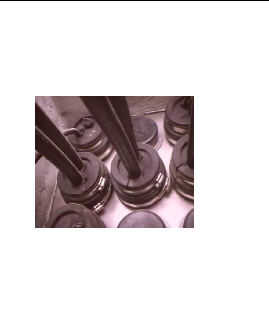
Installation Manual
iSiteC ODU3601C CDMA Soft Base Station Chapter 3 Installing RF Antenna and Feeder System
3-31
2) Direct the feeders into the equipment room via the feeder window. The
corresponding personnel inside the equipment room should guide the operation
so as to avoid damage to equipment in the room.
3) Mount sealing gasket and sealing gland. Place the hole for filling in glue on the
sealing gland facing upward when mounting the sealing gland.
4) Cut the feeders correctly according to the design requirements.
5) Make the indoor feeder connector.
6) Encapsulate the feeder window and the unused holes with adhesive tape, plaster
and glass cement, as shown in Figure 3-38.
Figure 3-38 Encapsulation treatment of the feeder window after feeder enters the equipment room
&
Note:
If the feeder needs to run though the window glass, remove the glass first. Cut a corner of proper size of
the glass and then use rubber or adhesive tape to protect the edge, in order to avoid the feeder being cut.
Measures should be taken to prevent rain after the feeder runs through the glass, that is, seal the
connection between the glass and the feeder with glass cement.
3.7.7 Connecting Feeder and ODU3601C
The feeder and ODU3601C should be connected with 1/2 jumper. Feeder connector at
ODU3601C side has already been connected during the installation of major
equipment. Just connect the feeder and jumper. In the case of outdoor installation of
ODU3601C, 3-layer waterproof treatment should be performed in addition.

Installation Manual
iSiteC ODU3601C CDMA Soft Base Station Chapter 3 Installing RF Antenna and Feeder System
3-32
3.8 System Testing
Use the Site Master to test the antenna and feeder system. Test the standing wave ratio
(SWR) of the feeders. The SWR should be smaller than 1.5 in engineering, yet the
SWR of the antenna and feeder system newly set up generally should be smaller than
1.3 (the corresponding return loss is 18dB).
For the usage of the Site Master, please refer to relevant operation instructions.

Installation Manual
iSiteC ODU3601C CDMA Soft Base Station Chapter 4 Installation Check
4-1
Chapter 4 Installation Check
Upon completion of all hardware installation, check the installation including the
following aspects: overall check, power-on check, environment condition check and
system commissioning.
4.1 Overall Check
4.1.1 Checking Equipment Installation
l All the equipment should be steady and neat in appearance when installed.
l All the bolts and nuts are fastened. And plain washers and spring washers are
applied under all the nuts with the plain washer under the spring washer.
l There should be no missing or damaged parts on the equipment, and all the
cables should be intact.
l The rack interior should be cleaned. Fingerprints and smudges left during the
installation should be cleaned. There should be no dust in the rack.
4.1.2 Checking Cable Connection
l Power cables should be well connected. The connector should not be loose or
damaged. And there should be no scratch or fissure on the power cable skin.
l Check whether the contact of the grounding cable is good.
l Check whether the trunk cable connections are secure and correct.
l All the cables should be secure. Do not over-strain the cables running round the
corner. Cables and fibers should run in straight and smooth courses without any
cross. Cables and fibers in the same direction should be bundled up. The cable
layout should be neat and tidy with the same bundling space. Signal cables cannot
be bundled with power cables and grounding cables.
l There should be no damage to the skin of all the cables.
4.1.3 Checking Lightning Protection Grounding
I. Checking outdoor grounding
Outdoor grounding check includes the following aspects:
l Outdoor grounding bar should be connected to the counterpoise with grounding
bus. DO NOT connect the outdoor grounding bus to the grounding flat steel of the
feeder lightning arrester.

Installation Manual
iSiteC ODU3601C CDMA Soft Base Station Chapter 4 Installation Check
4-2
l Check whether there is good electrical connection between the UPS shell and the
UPS external box via screws. UPS external box should be grounded.
l Check whether the protection grounding cable of AC lightning protection box or
IAFB is directly connected to the protection grounding bar. Make sure the
grounding cable is shorter than 1m.
l The AC power cable from the exterior to the ODU3601C should be directly
connected to the AC lightning protection box (when AC lightning protection box is
available) or to the IAFB (when AC lightning protection box is unavailable). It is not
allowed to connect the external power cable to the power distribution terminal in
the work box first and then to the AC lightning protection box.
l In ODU3601C outdoor tower installation mode, the shielding covering of the
ODU3601C coaxial feeder should be grounded at the tower-top and the front end
connecting the ODU3601C. The grounding cable should be connected to the
tower body nearby. The protection grounding bar should have separate grounding
donwlead that is not insulated from the tower body.
l When the feeder is not shorter than 60m, the shielding covering of the coaxial
feeder should be grounded at the middle of the tower body.
II. Checking indoor grounding
Indoor grounding check includes the following aspects:
l In ODU3601C indoor installation, there should be indoor grounding bar and
outdoor grounding bar that should be led into the counterpoise separately instead
of being connected in series directly with grounding cables.
l The grounding cable at the point where the feeder enters the feeder window is
connected to the outdoor grounding bar in the direction from the antenna to the
ODU3601C.
l The AC lightning protection box provides separate grounding cable to connect to
the indoor grounding bar. The grounding cable from the AC lightning protection
box or from the IAFB to the indoor grounding bar should be shorter than 1m.
l Check whether there is good electrical connection between the UPS shell and the
UPS external box via screws. UPS external box should be grounded.
l The shielding covering of the coaxial feeder should be well grounded at the
tower-top, tower-bottom and the outside of the entrance to the equipment room.
When the feeder is not shorter than 60m, the shielding covering of the coaxial
feeder should be grounded at the middle of the tower body.
l The outdoor grounding bar and indoor protection grounding bar should share the
counterpoise of the equipment room. The outdoor grounding bar should not be
connected to the tower counterpoise for grounding.
l The feeder skin should be grounded after the feeder enters the equipment room.
The grounding cable from the feeder skin should be directly connected to the
indoor grounding bar.

Installation Manual
iSiteC ODU3601C CDMA Soft Base Station Chapter 4 Installation Check
4-3
4.2 Power-on Check
1) Check whether the voltage of the power supply is normal (normal voltage range:
150VAC~300VAC). If it is normal, turn on the power switch of the ODU3601C and
check whether the indicators on the power supply module of the ODU3601C are
normal. Please refer to User Manual for indicator descriptions.
2) Observe the running of boards and modules. Cut off the power supply immediately
in case of any exception. Power on all the boards and modules after the fault is
removed.
4.3 Checking Environment Condition
1) There should be no sundries inside or on top of the sun-shading cover. The cover
should be clean without any smudge or fingerprint.
2) There should be no redundant tape or cable tie on the cable.
3) There should be no tape, cable tie head, waste paper, or packing bag around the
ODU3601C.
4) All the things around the ODU3601C should be clean and neat in their original
appearance.

Installation Manual
iSiteC ODU3601C CDMA Soft Base Station Chapter 5 Software Installation and System Commissioning
5-1
Chapter 5 Software Installation and System
Commissioning
5.1 Software Installation
ODU3601C software indicates the running software of MTRM, which has been
installed before delivery and supports the remote loading through OMC. The
operation and maintenance of ODU3601C is realized through the upper-level BTS or
remote OMC, i.e. the ODU3601C needs no special operation and maintenance
software.
5.2 System Commissioning
Before starting the ODU3601C, make sure that its upper-level BTS runs normally.
Start certain basic operation and maintenance functions for system commissioning
after the ODU3601C is power-on and various indicators are normal. Following is to
introduce the contents of the system commissioning.
5.2.1 Test Equipment
I. Call generator
It is used to simulate multi-user call setup.
II. Test MS
It is used to test the service functions.
5.2.2 Service Flow Overview
When switched on, an MS may be either in the idle mode or the dedicated mode. In
the idle mode, the MS will monitor the radio surroundings and find a suitable service
cell to stay; then the MS will monitor the paging channel in the service cell so as to
receive the paging messages from the network side. In the dedicated mode, the MS
exchanges signaling and data with the network.
The basic flow is as follows:
1) Location update flow

Installation Manual
iSiteC ODU3601C CDMA Soft Base Station Chapter 5 Software Installation and System Commissioning
5-2
2) Mobile Originated Call (MOC) flow
3) Mobile Terminated Call (MTC) flow
4) Handoff flow
5) Mobile originated SMS flow
6) Mobile terminated SMS flow
7) Mobile originated call packet data flow
8) MS packet data flow (downlink service rate)
Flows 1), 2), 3), and 4) are of basic radio connection; while flows 5), 6), 7), and 8) can
be independent flows, or be additional part of flows 1), 2), 3), and 4).
5.2.3 Test of Location Update Flow
I. Test condition
The test MS has been defined in HLR.
II. Test steps
1) Make sure the network data setting is correct.
2) Switch on the test MS
3) Observe the signaling on Abis interface.
III. Expected test result
By tracing the signaling on Abis interface, the possible results of the location update
include:
1) The network side accepts the MS location update request;
2) The network side rejects the MS location update request.
5.2.4 Test of MOC Flow
I. Test condition
This test should be conducted after a successful location update flow, when the MS
should display the current PLMN No. or operator name.
II. Test steps
Call a PSTN subscriber with the MS.
III. Expected test result
In normal cases, the called PSTN subscriber establishes a bidirectional conversation
with the MS after ringing and off-hook.

Installation Manual
iSiteC ODU3601C CDMA Soft Base Station Chapter 5 Software Installation and System Commissioning
5-3
5.2.5 Test of MTC Flow
I. Test condition
This test must be preceded by a successful location update flow. The called MS
should reside in the coverage of the tested ODU3601C, and display the current
PLMN No. or operator name of the network.
II. Test steps
Call the test MS from a PSTN telephone set.
III. Expected test result
In normal cases, the test MS establishes a conversation with the calling PSTN
subscriber after ringing and off-hook.
5.2.6 Test of Handoff Flow
I. Test condition
1) This test should be performed after the above three tests and in the area
covered by at least two cells. One of cell should be configured with several
sectors, so that the test of the softer handoff can be conducted.
2) The sectors (or omni cells) that compose the overlapped radio coverage should
be configured with different frequencies, so that the hard handoff can be
conducted.
3) The related handoff data should have been configured;
4) Dedicated test MSs;
5) Change the IMSI of the MS, and redefine the subscriber. In this way, the MS can
access the network by selecting a certain basic frequency or auxiliary frequency
in the sector (or omni cell) that is configured with multiple frequencies.
II. Test steps
1) Use an MS to call a PSTN subscriber and establish a conversation.
2) Move the MS from the source sector to the adjacent sector within the same cell
to test the softer handoff performance.
3) Only when the adjacent sector is also configured with the frequency at which the
MS has established the conversation in the source sector, and the frequency is
available, can the softer handoff be achieved.
4) Move the MS from the source cell to the target cell to test the soft/hard handoff
performance.

Installation Manual
iSiteC ODU3601C CDMA Soft Base Station Chapter 5 Software Installation and System Commissioning
5-4
When the MS establishes a connection at a frequency in the source cell, while the
target cell is not configured with this frequency, the hard handoff will occur. If the
target cell is configured with this frequency and this frequency is available, the soft
handoff will occur.
III. Expected test result
1) Soft handoff and softer handoff
Normally, when the MS moves to the adjacent cell/sector, the target pilot channel will
be shown in the active set of the MS pilot set.
During the conversation, the mobile subscriber feels no interruption or call drop, and
the voice quality is good.
2) Hard handoff
Normally, when the MS moves to the adjacent cell or sector, it is visible in the active
set of the MS pilot set that the source pilot channel is deleted, and the target pilot
channel is added.
The mobile subscriber will feel temporary conversation interruptions.
&
Note:
If the actual test conditions cannot meet the standard, the test flow can be simplified like this: Make an
MOC/MTC, and move the MS repeatedly between the adjacent cells, or between the adjacent sectors in
one cell. Whether the handoff flow is normal or not can be judged by observing whether or not there are
conversation interruptions, and by the voice quality.
5.2.7 Test of Mobile Originated SMS Flow
I. Test condition
1) The test should be performed after the location update flow test;
2) The system must be configured with Message Center (MC);
II. Test steps
Use an idle MS to send an short message through the specified MC.

Installation Manual
iSiteC ODU3601C CDMA Soft Base Station Chapter 5 Software Installation and System Commissioning
5-5
III. Expected test result
In normal cases, the MS that originates the short message will prompt that the short
message has been transmitted successfully. The corresponding short message can
be queried at the MC.
5.2.8 Test of Mobile Terminated SMS Flow
I. Test condition
Location update flow test is completed.
II. Test steps
Input an short message to MC properly. The receiver of the short message is the test
MS that is in the idle status.
III. Expected test result
In normal cases, the called MS will ring to indicate that the MS has received the short
message and is ready to display the content of the SM.
5.2.9 Test of Mobile Originated Packet Data Flow
I. Test condition
1) A cdma2000 1X MS, a set of BlueRose and a ready FTP server;
2) The system adopts dynamic rate allocation.
II. Test steps
1) Use the BlueRose to control the process of the test MS logging in to FTP server,
and originate the FTP downloading;
2) Observe the signaling flow and the status transition of MS on BlueRose;
3) Check the channel setup of the sector.
III. Expected test result
1) The MS successfully logs in to the FTP server, and transits from the idle status
to the downloading status.
2) After the Fundamental Channel (FCH) is set up, ODU3601C repeatedly issues
the ESCAM message and performs the Supplemental Channel (SCH) setup or
SCH extension.

Installation Manual
iSiteC ODU3601C CDMA Soft Base Station Chapter 5 Software Installation and System Commissioning
5-6
5.2.10 Test of MS Packet Data Flow (Downlink Service Rate)
I. Test condition
1) The system adopts dynamic rate allocation;
2) A cdma2000 1X MS, a set of BlueRose and a ready FTP server;
II. Test steps
After the MS logs in to the FTP server under the control of the BlueRose, originate
the FTP file downloading, and test the downlink rate of a single subscriber under the
following conditions respectively:
--The adjacent cell and target sector are not loaded. The MS is stationary, and is
within short distance to the ODU3601C.
--The adjacent cell and target sector are not loaded. The MS is stationary, and is
within long distance to the ODU3601C.
--The adjacent cell and target sector are not loaded, and the MS is moving (15, 30,
70km/h), and is within short distance to the ODU3601C.
--The adjacent cell and target sector are not loaded, and the MS is moving (15, 30,
70km/h), and is within long distance to the ODU3601C.
--The adjacent cell is 100% loaded. The target sector is 50% loaded. The MS is
stationary, and is within short distance to the ODU3601C.
--The adjacent cell is 100% loaded. The target sector is 50% loaded. The MS is
stationary, and is within long distance to the ODU3601C.
--The adjacent cell is 100% loaded. The target sector is 50% loaded. The MS is
moving (15, 30, 70Km/h), and is within short distance to the ODU3601C.
--The adjacent cell is 100% loaded. The target sector is 50% loaded. The MS is
moving (15, 30, 70Km/h), and is within long distance to the ODU3601C.
III. Expected test result
In normal cases, the downlink data service rate keeps stable.
&
Note:
There are multiple test conditions listed in the test steps. It does not mean that all of them are necessary
during the actual test.

Installation Manual
iSiteC ODU3601C CDMA Soft Base Station Chapter 5 Software Installation and System Commissioning
5-7
5.2.11 Processing of Abnormalities in the Test
In normal cases, the above flows can pass the test. When abnormalities occur in the
test, they cannot be all attributed to the fault of ODU3601C.
The service flow test does not only test ODU3601C, but also the whole CDMA 1X
system. The parts tested include BTS3612, ODU3601C and BSC6600 of BSS.
Besides, also tested are MSC/VLR, HLR, and AUC of the NSS and their interfaces to
PSTN and Internet. The fault of any part of the system may result in the failure of the
flow. Therefore, the analysis should be made based on the actual conditions when a
fault occurs.
ODU3601C is responsible only for the radio transmission. If the MS can access the
network and set up the radio service link, then we say the ODU3601C is in normal
operation.
Take the location update flow as the example. If a location update request is rejected,
basically it is due to the abnormality of the network equipment, or to be more specific,
the problem with the data setting of HLR. Based on the rejection reason in the
message for the rejected location update, further cause for the rejection can be
figured out.