Huawei Technologies PBTS3701-2500 WiMAX Pico Base Station User Manual
Huawei Technologies Co.,Ltd WiMAX Pico Base Station
Contents
- 1. Safety Manual
- 2. User Manual
User Manual
Huawei Proprietary
Copyright © Huawei Technologies Co., Ltd.

1 pBTS3701 User Guide
About This Chapter
Purpose
This guide describes the hardware, installation, commissioning, and maintenance of the
pBTS3701.
Related Versions
The following table lists the product versions related to this document.
Product Name Version
pBTS3701 V100R002
Intended Audience
The intended audiences of this document are:
lBS installer
lAdministration engineer
lSystem maintenance engineer
lField maintenance engineer
lData configuration engineer
Update History
Version Update History
01(2008-09-24) Initial release.
1 pBTS3701 User Guide
Issue () Huawei Proprietary
Copyright © Huawei Technologies Co., Ltd.
1-1

1.1 Introduction to the pBTS3701
The pBTS3701 is a compact integrated indoor BTS. It receives and transmits radio signals to
enable communications between the WiMAX network and the MS/SS.
1.1.1 Components of the pBTS3701
This describes the console, GPS antenna, and power adapter of the pBTS3701.
1.1.2 Physical Structure
The pBTS3701 is a compact integrated indoor BTS, and it is small and exquisite.
1.1.3 Cables of the pBTS3701
This describes the cables of the pBTS3701. The pBTS3701 requires two kinds of cables: the
power cable and the Ethernet cable.
1.1.1 Components of the pBTS3701
This describes the console, GPS antenna, and power adapter of the pBTS3701.
The hardware of the pBTS3701 consists of following parts:
lConsole
lGPS antenna
lPower adapter
Console
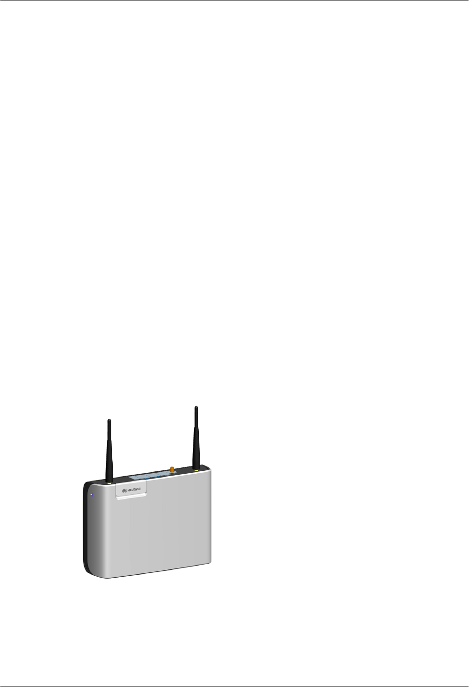
Figure 1-1 shows the console of the pBTS3701.
Figure 1-1 Console of the pBTS3701
The console of the pBTS3701 is integrated with the clock module, baseband module, IRF
module, OM module, transmission module, and power module.
GPS Antenna
Figure 1-2 shows the GPS antenna of the pBTS3701.
1 pBTS3701 User Guide
Issue () Huawei Proprietary
Copyright © Huawei Technologies Co., Ltd.
1-3
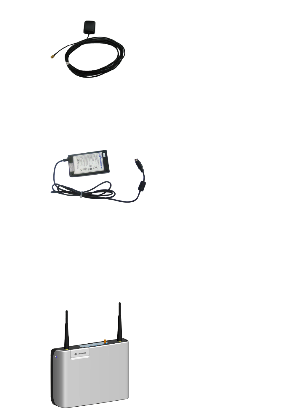
Figure 1-2 GPS antenna of the pBTS3701
The GPS antenna of the pBTS3701 is used to receive GPS clock signals, which are used as the
guarantee the synchronization of the pBTS3701.
Power Adapter
Figure 1-3 shows the power adapter of the pBTS3701.
Figure 1-3 Power adapter of the pBTS3701
The power adapter is used to convert 110 or 220 V AC into +12 V DC to supply power to the
pBTS3701.
1.1.2 Physical Structure
The pBTS3701 is a compact integrated indoor BTS, and it is small and exquisite.
Appearance
Figure 1-4 shows the appearance of the pBTS3701.
Figure 1-4 Appearance of the pBTS3701
1 pBTS3701 User Guide
1-4 Huawei Proprietary
Copyright © Huawei Technologies Co., Ltd.
Issue ()

Button
At the top left of the pBTS3701, there is a RST button used to reset the pBTS3701.
Ports
The Figure 1-5 shows the ports of the pBTS3701.
Figure 1-5 Ports of the pBTS3701
Table 1-1 lists the ports of the pBTS3701.
Table 1-1 Ports of the pBTS3701
Label Type Number Description
GPS SMA 1 The GPS port is used to receive GPS signals.
ETH RJ45 1 The ETH port is used for maintenance and
commissioning.
FE: 10 Mbit/s or 100 Mbit/s
TRAN RJ45 1 The TRAN port is a service port which connects to
connect the transmission equipment or gateway
equipment.
FE/GE: 10 Mbit/s or 100 Mbit/s or 1000 Mbit/s
PWR 4Pin socket 1 The PWR port is a power input port. It supports a
+12 Vdc power input.
TST USB 1 Clock test port
LEDs
Figure 1-6 shows the LEDs of the pBTS3701.
1 pBTS3701 User Guide
Issue () Huawei Proprietary
Copyright © Huawei Technologies Co., Ltd.
1-5
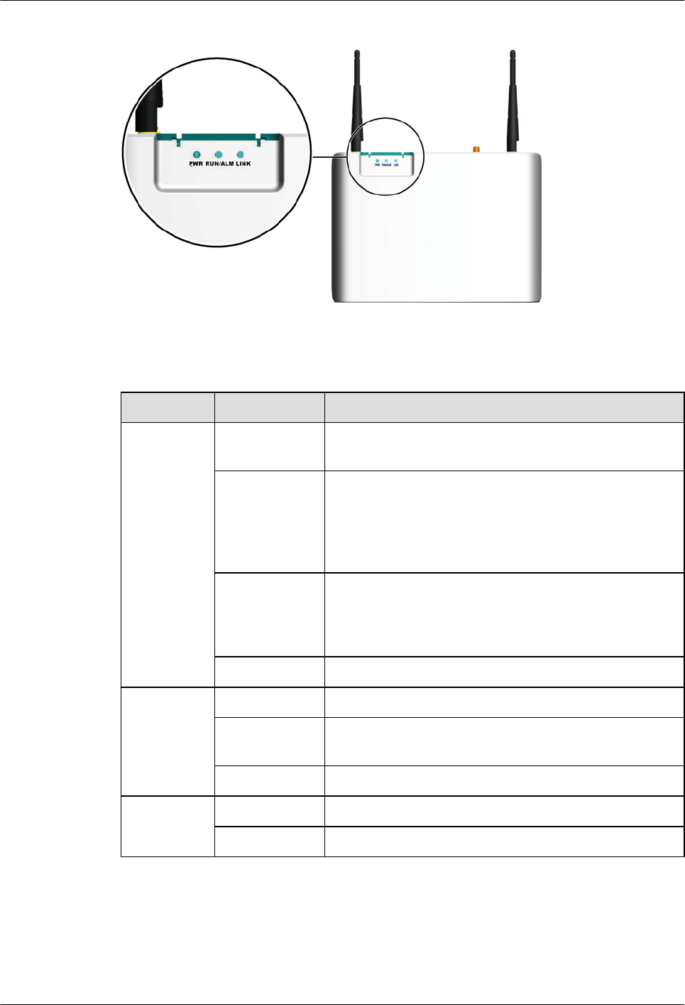
Figure 1-6 LEDs of the pBTS3701
Table 1-2 lists the LEDs of the pBTS3701.
Table 1-2 LEDs of the pBTS3701
Label Status Description
RUN/ALM ON (red) An alarm is generated, indicating that the board is running
in the faulty status.
Blinks once
every 0.25
seconds (Green,
ON for 0.125s ,
OFF for 0.125s)
The board is being loaded.
Blinks once
every 2 seconds
(Green, ON for
1s , OFF for 1s)
The board is running normally.
OFF There is no power input, or the board is faulty.
LINK ON (Green) The pBTS3701 is connected to the network normally.
Blinking
(Green)
The pBTS3701 is in IP packets transmission.
OFF The pBTS3701 is not connected to the network.
PWR ON (green) Power supply to the pBTS3701 is functional.
OFF No power is supplied to the pBTS3701.
1.1.3 Cables of the pBTS3701
This describes the cables of the pBTS3701. The pBTS3701 requires two kinds of cables: the
power cable and the Ethernet cable.
1 pBTS3701 User Guide
1-6 Huawei Proprietary
Copyright © Huawei Technologies Co., Ltd.
Issue ()
1.1.3.1 Power Cable of the pBTS3701
This describes the power cable of the pBTS3701.
1.1.3.2 Ethernet Cable of the pBTS3701
This describes the Ethernet cable of the pBTS3701. The Ethernet cable is used to connect the
pBTS3701 with a LAN switch, through which the connection with the ASN-GW is realized.
The use of Ethernet cable is optional.
Power Cable of the pBTS3701
This describes the power cable of the pBTS3701.
Appearance
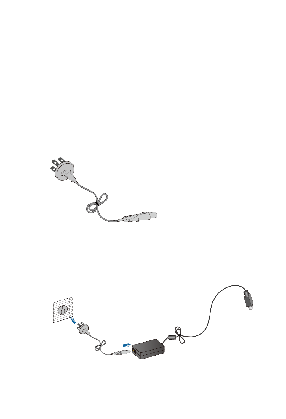
As shown in Figure 1-7, one end of the power cable of the pBTS3701 is a three PIN plug, and
the other end is a three PIN female connector.
Figure 1-7 Power cable
Installation Position
The three-PIN plug of the power cable is connected to the socket of mains power supply, and
the other end is connected to the adapter, as shown in Figure 1-8.
Figure 1-8 Connection of the power cable
Ethernet Cable of the pBTS3701
This describes the Ethernet cable of the pBTS3701. The Ethernet cable is used to connect the
pBTS3701 with a LAN switch, through which the connection with the ASN-GW is realized.
The use of Ethernet cable is optional.
1 pBTS3701 User Guide
Issue () Huawei Proprietary
Copyright © Huawei Technologies Co., Ltd.
1-7
Appearance
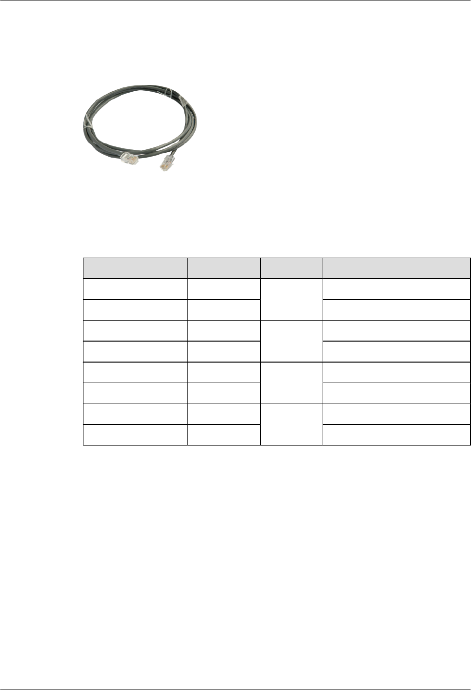
Both ends of the pBTS3701 Ethernet cable are RJ45 connectors, as shown in Figure 1-9.
Figure 1-9 Ethernet cable of the pBTS3701
Pin Assignment
Table 1-3 describes the pin assignment for the wires comprising the pBTS3701 Ethernet cable.
Table 1-3 Pin assignments for the wires of the pBTS3701 Ethernet cable
X1 End Wire Color Wire Type X1 End
X1.2 Orange Twisted pair
cable
X2.2
X1.1 White/orange X2.1
X1.6 Green Twisted pair
cable
X2.6
X1.3 White/green X2.3
X1.4 Blue Twisted pair
cable
X2.4
X1.5 White/blue X2.5
X1.8 Brown Twisted pair
cable
X2.8
X1.7 White/brown X2.7
Installation Position
For the Ethernet cable used to transmit user traffic, one end is connected to the TRAN port on
the pBTS3701, and the other end to the LAN switch. For the one used to perform local
maintenance is connected to the ETH port, and the other end to the computer for local
maintenance.
1 pBTS3701 User Guide
1-8 Huawei Proprietary
Copyright © Huawei Technologies Co., Ltd.
Issue ()