Huawei Technologies PRU01B04 pRRU Multi-Mode Radio Unit User Manual Installation Guide
Huawei Technologies Co.,Ltd pRRU Multi-Mode Radio Unit Installation Guide
UserManual.wiki
>
Huawei Technologies
>
PRU01B04 User Manual
>
Host Manual
Contents
1.
Host Manual
2.
Regulatory Compliance Statement
Host Manual
Navigation menu
Upload a User Manual
Namespaces
Wiki Guide
HTML
PDF
Info
Views
User Manual
Discussion / Help
Navigation
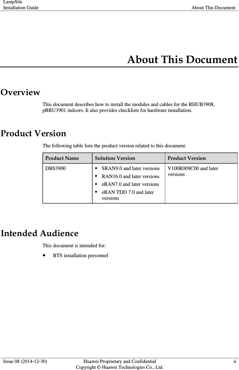
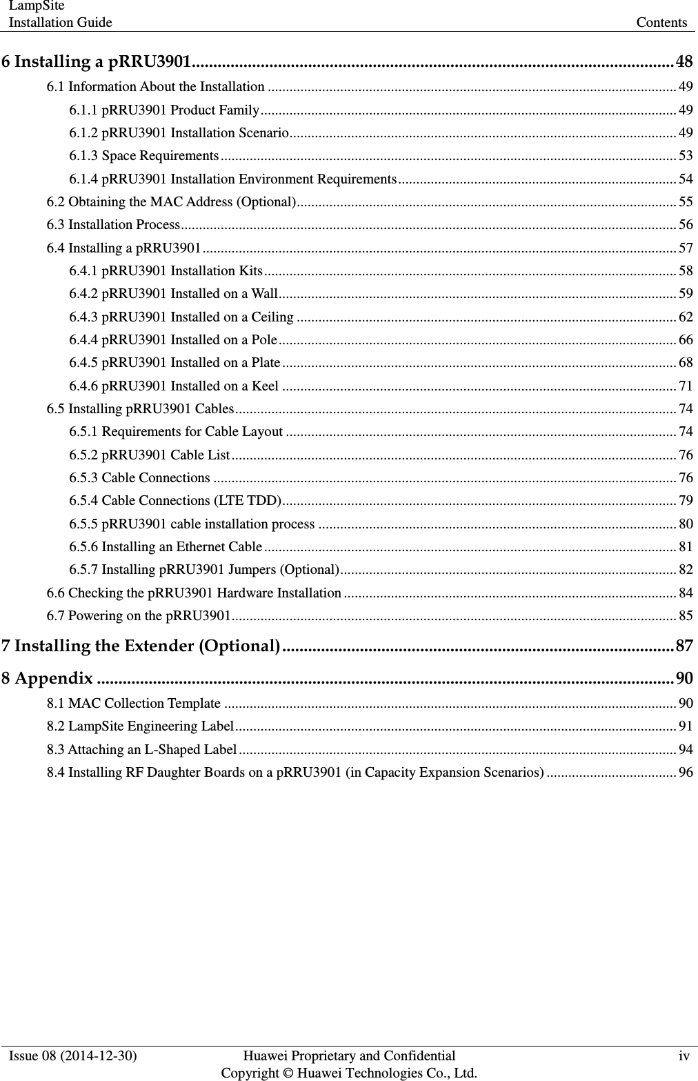
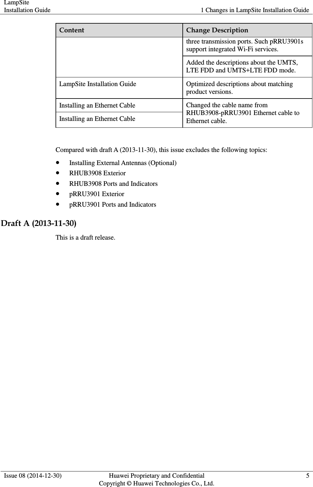
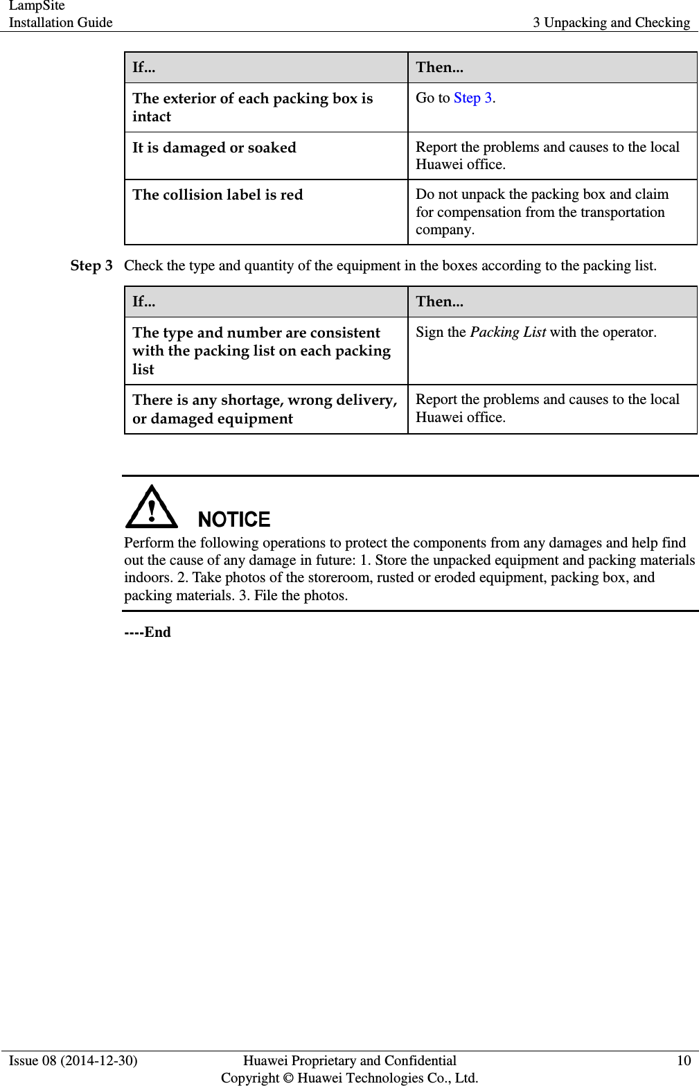
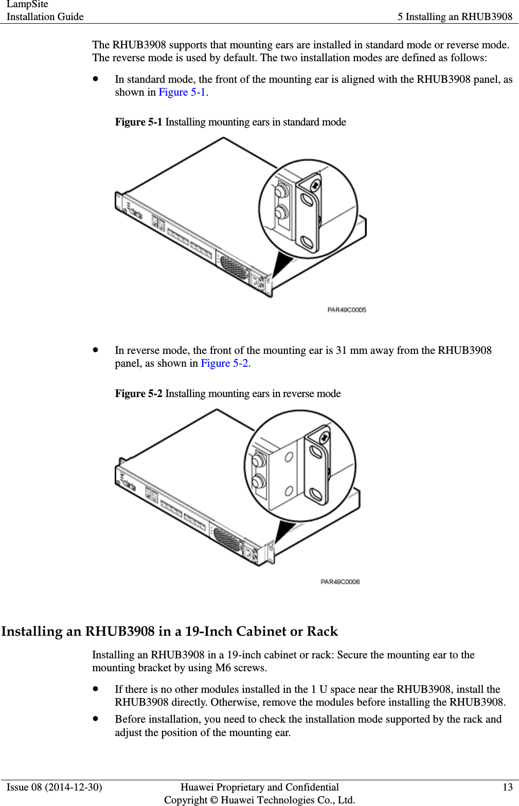
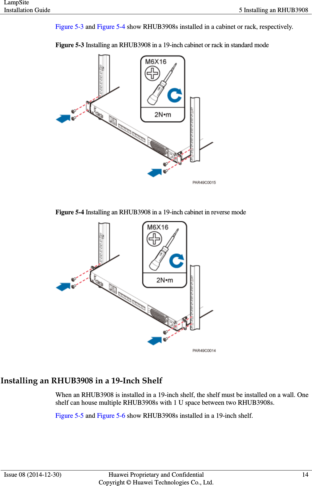
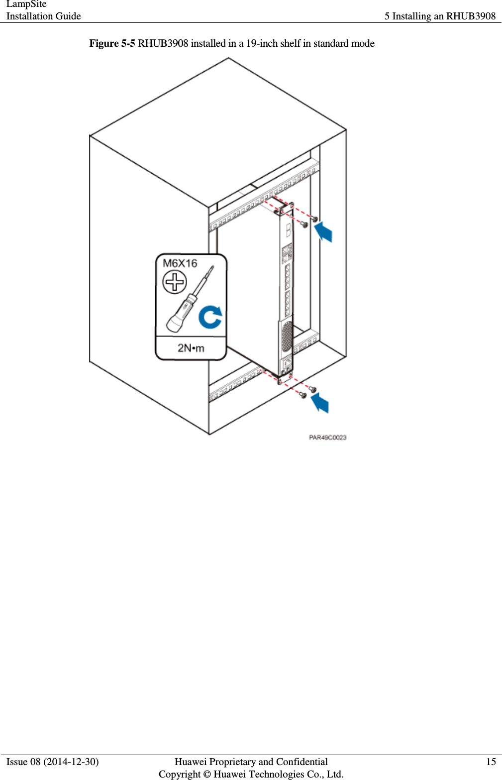
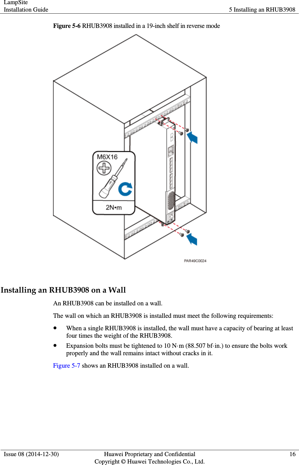
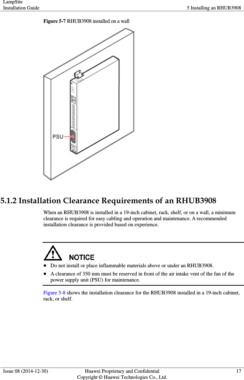
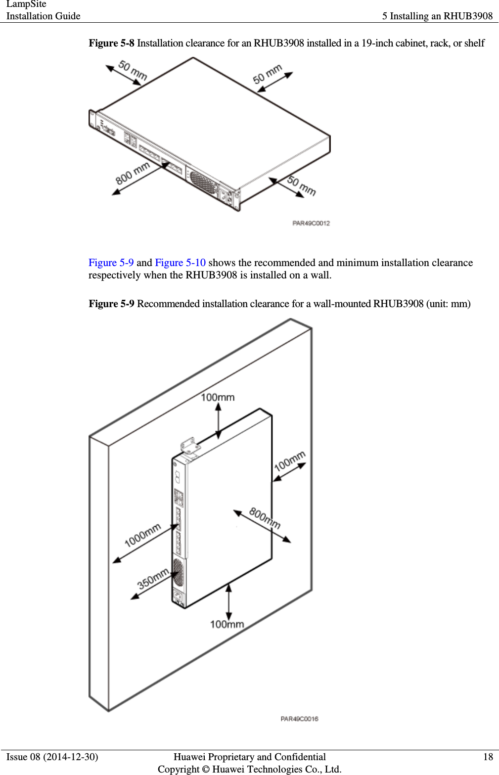
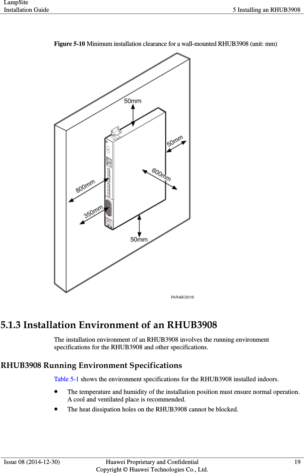
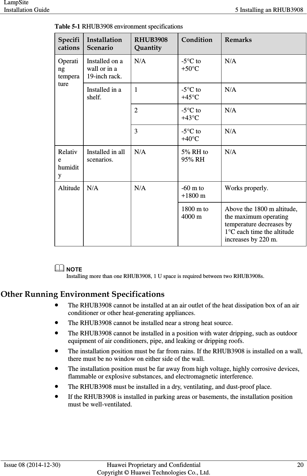
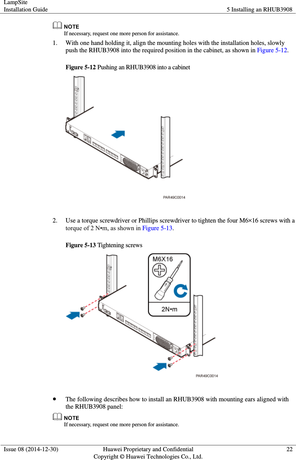
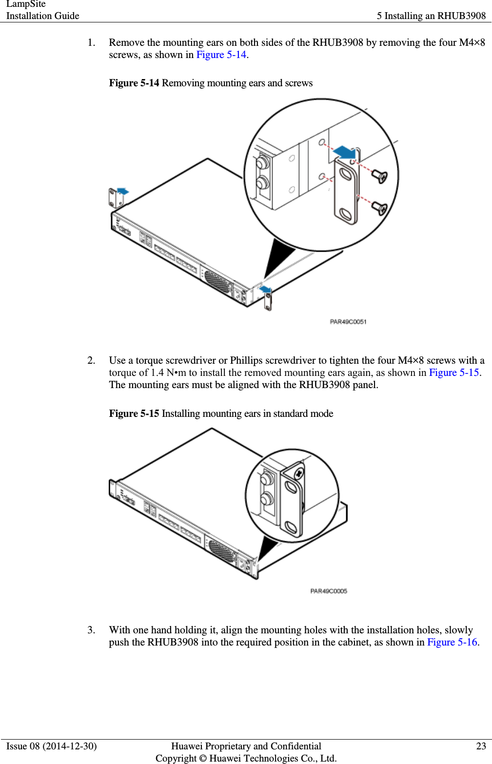
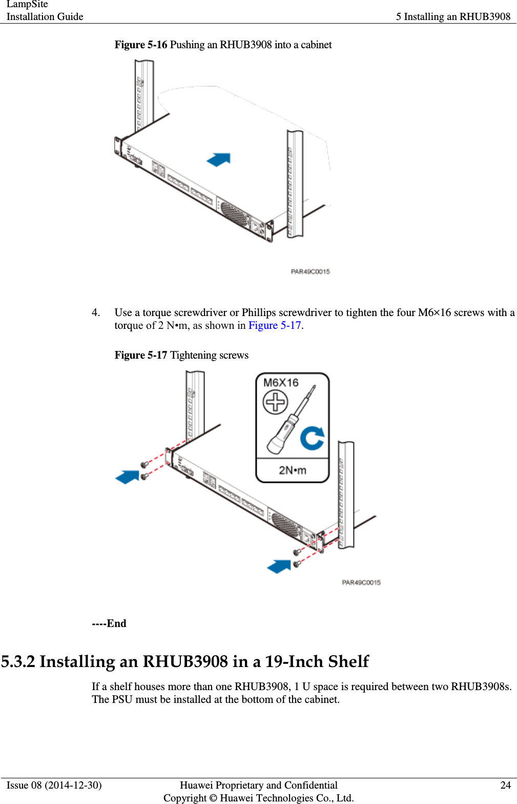
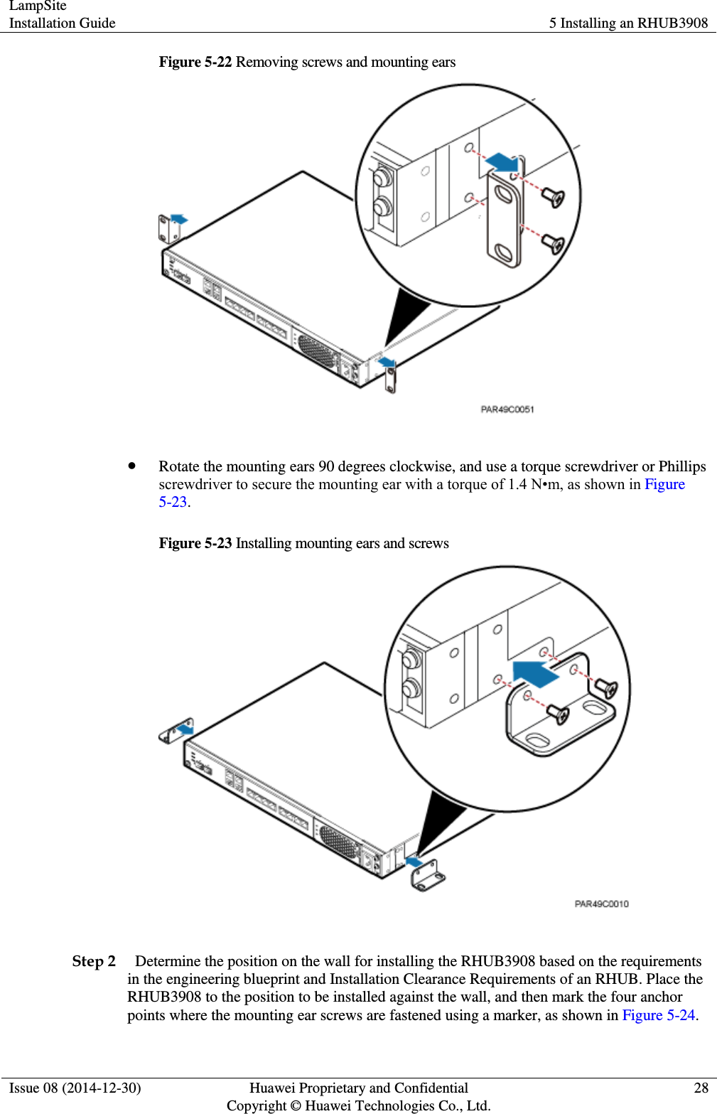
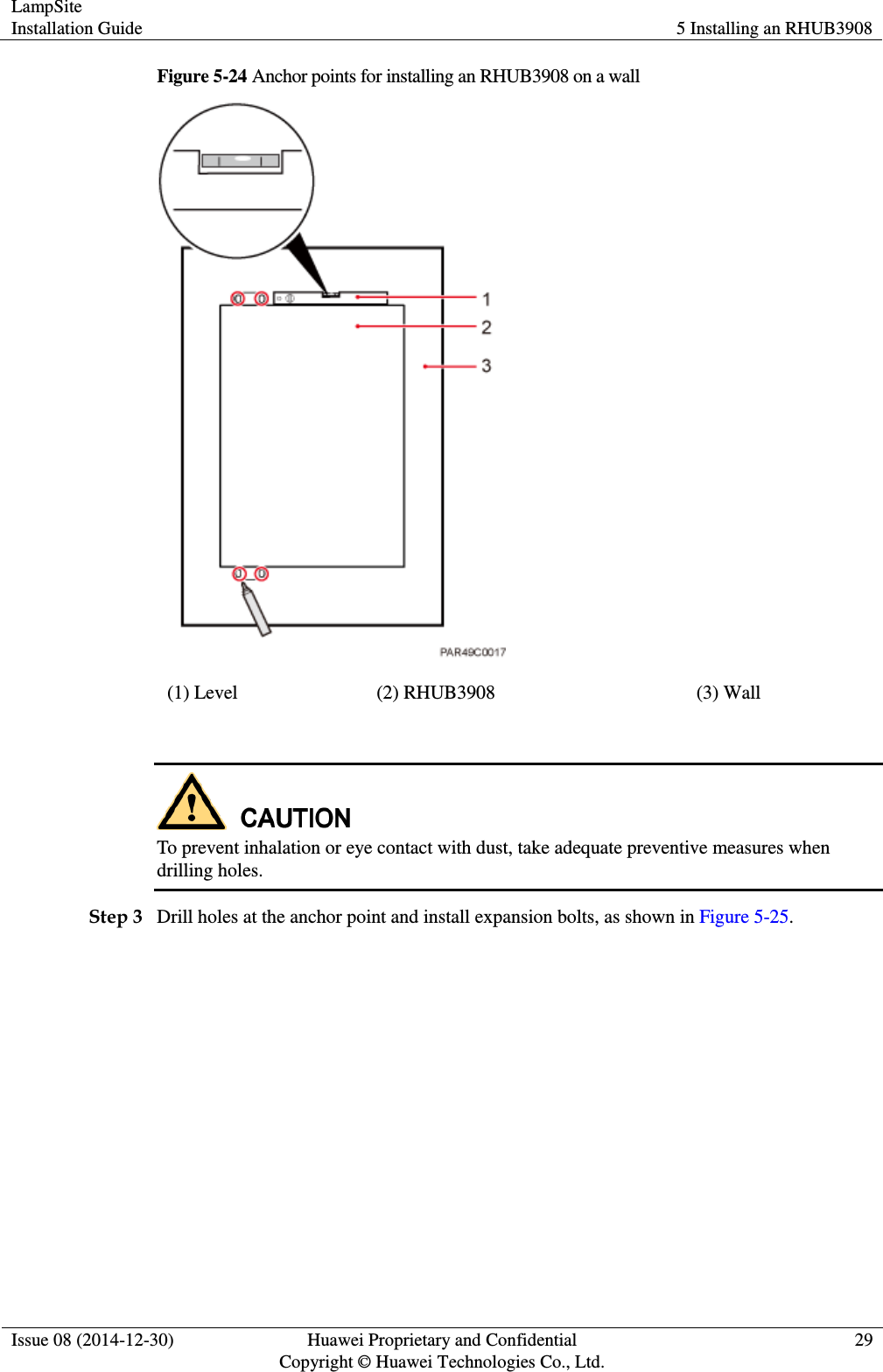
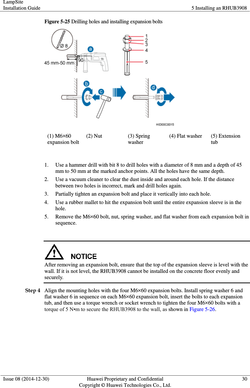
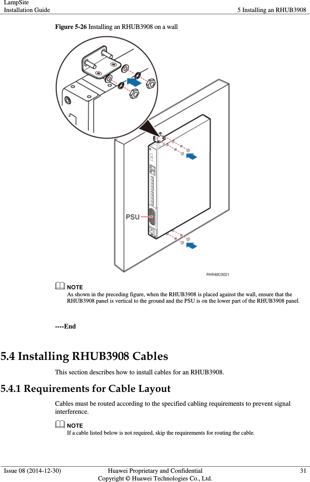
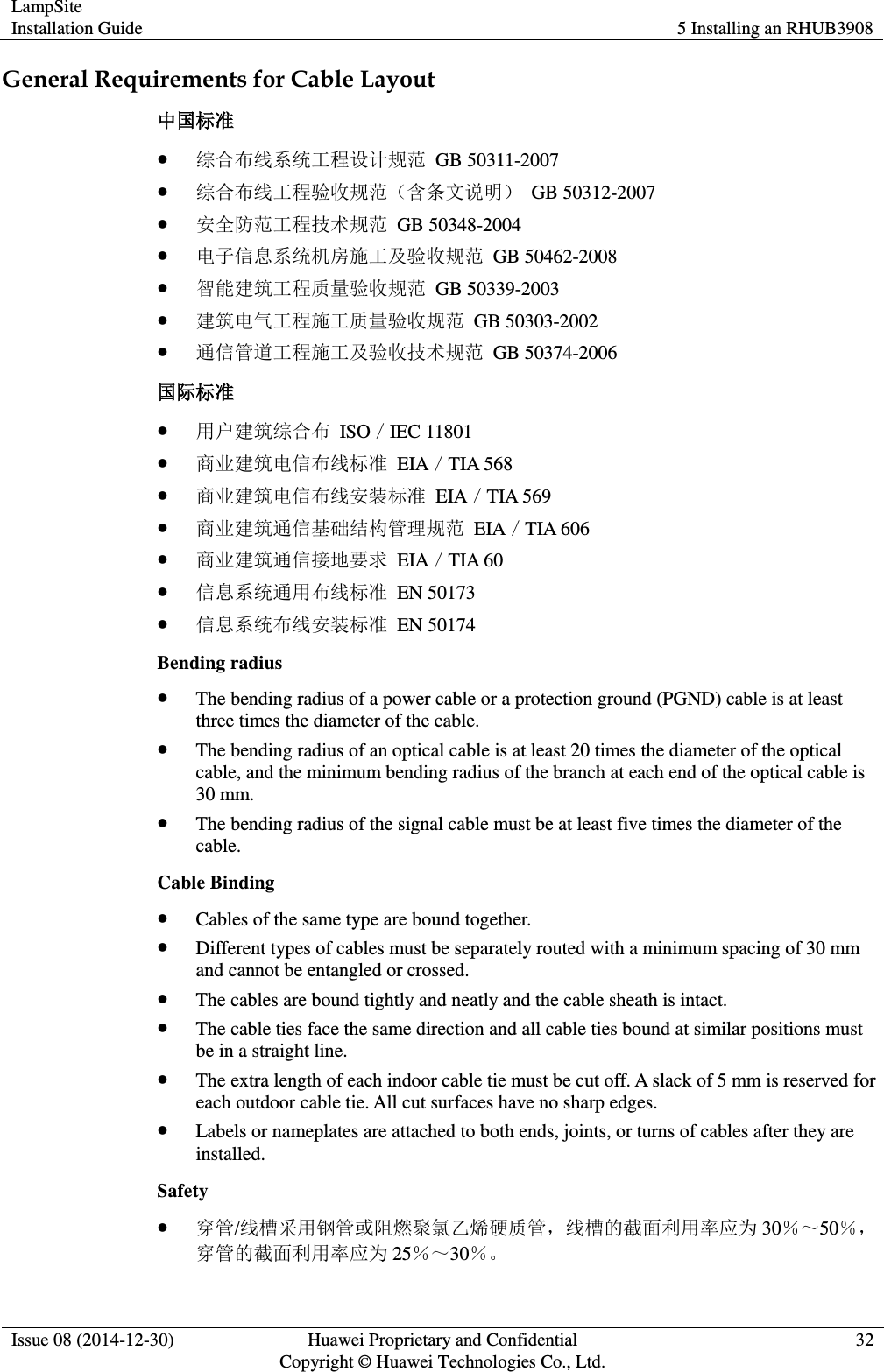
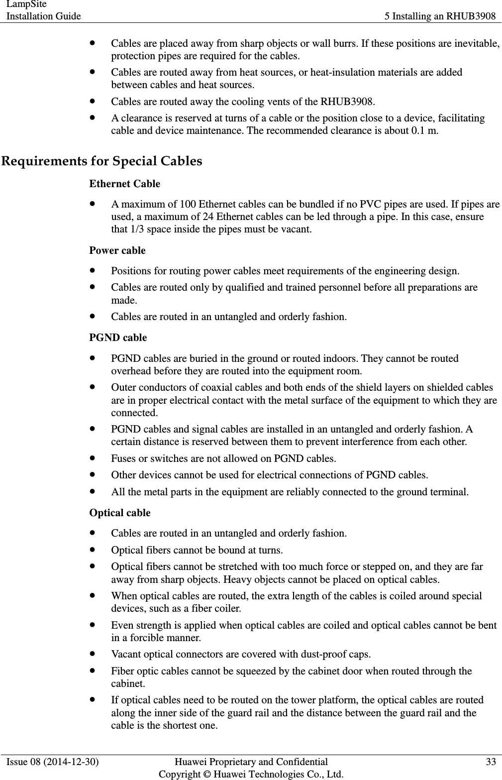
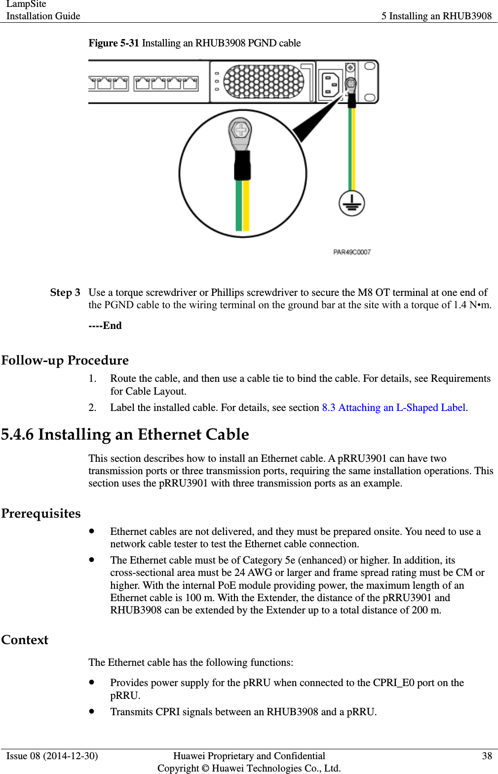
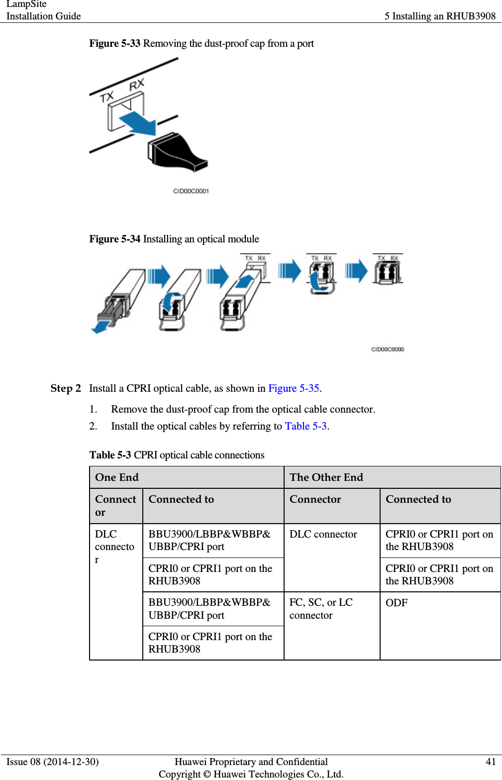
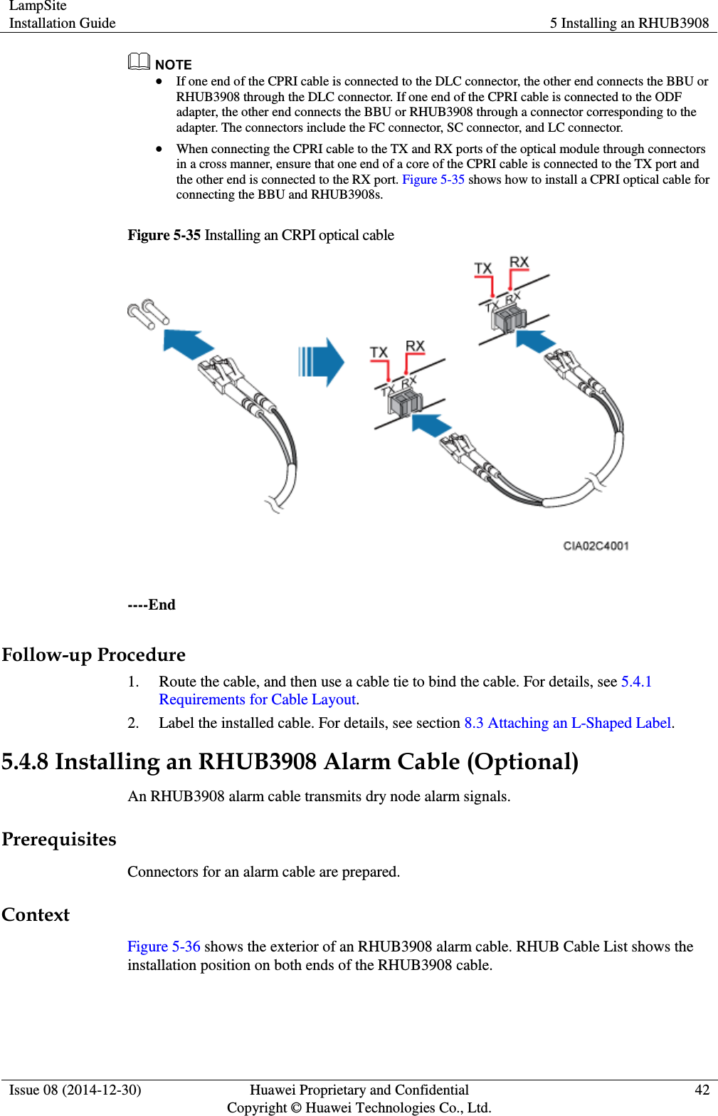
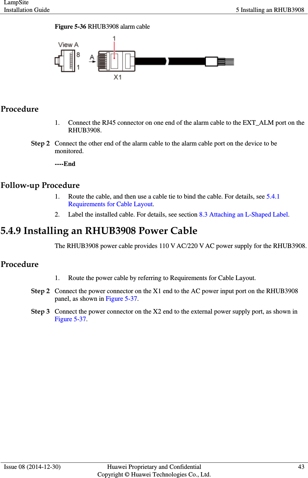
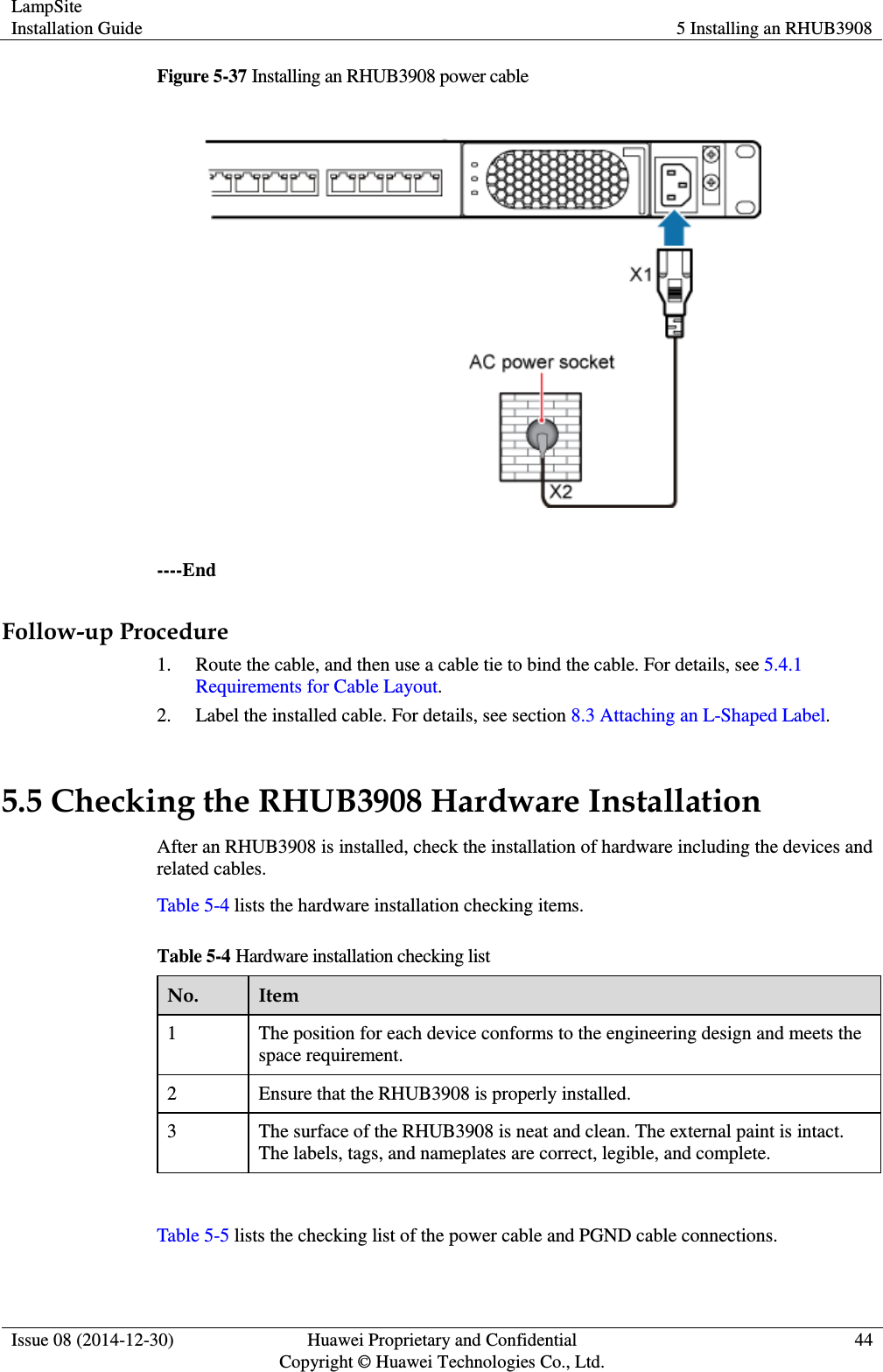
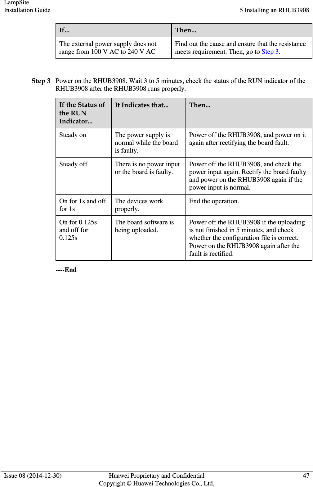
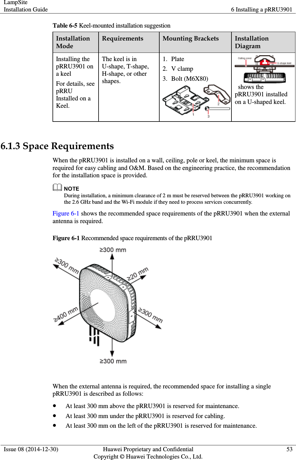
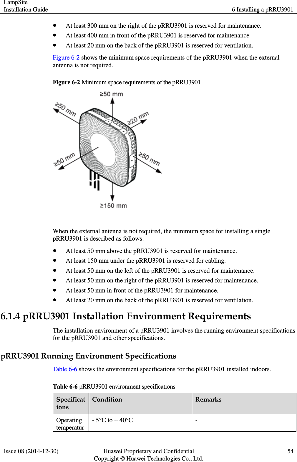
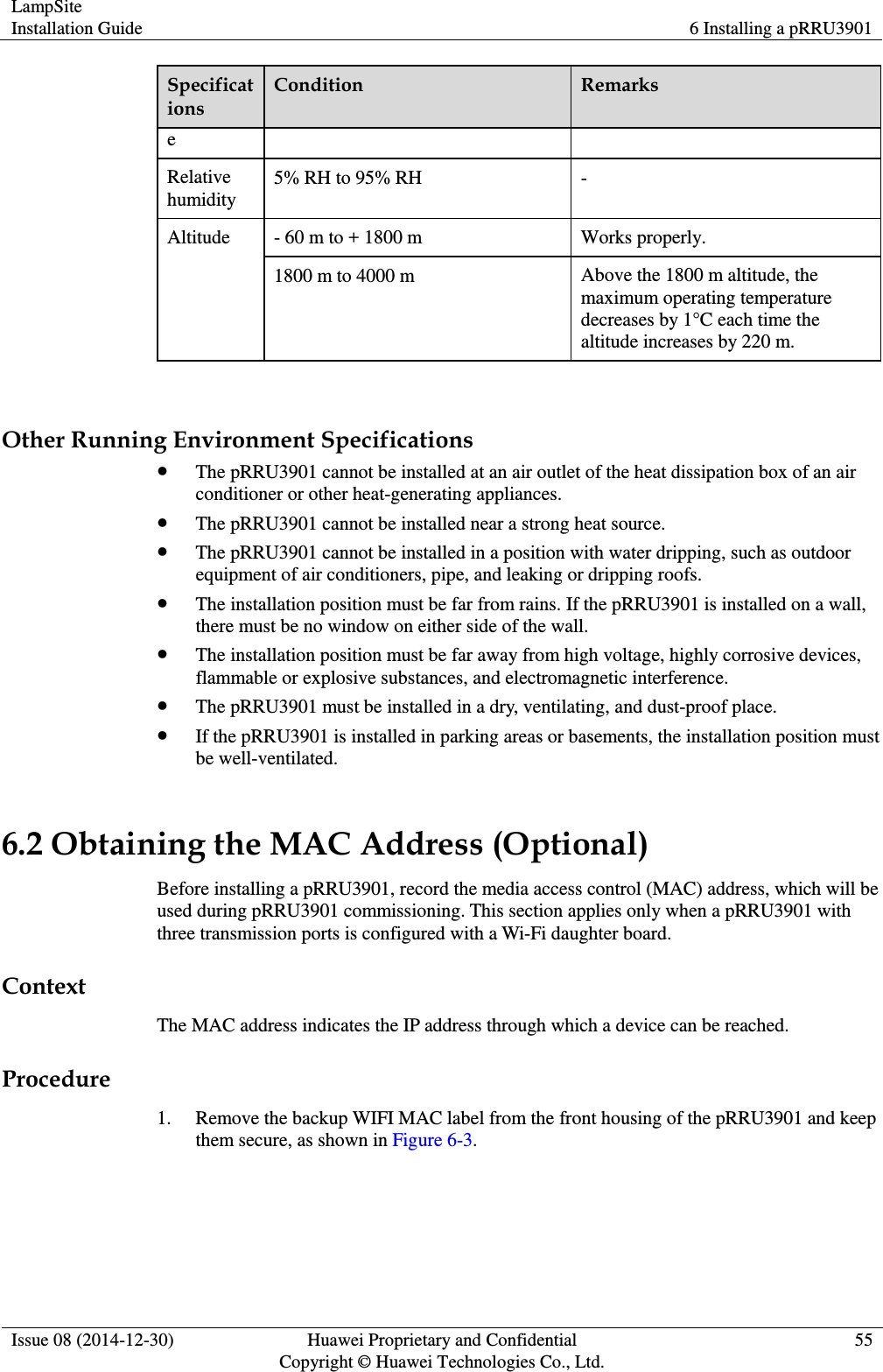
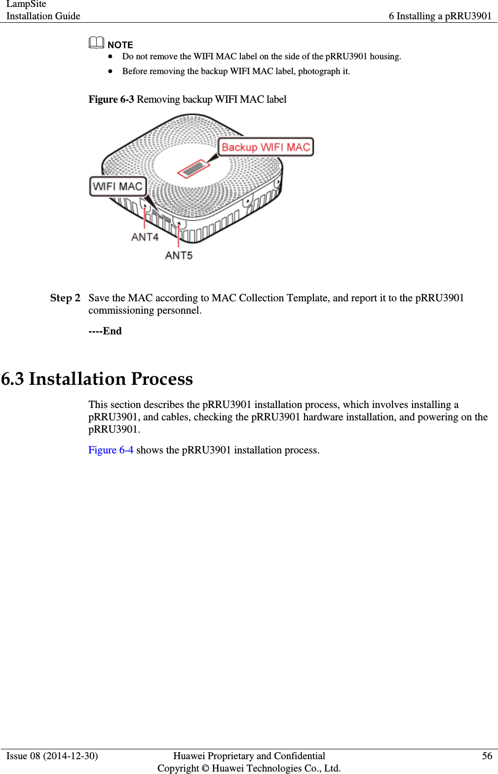
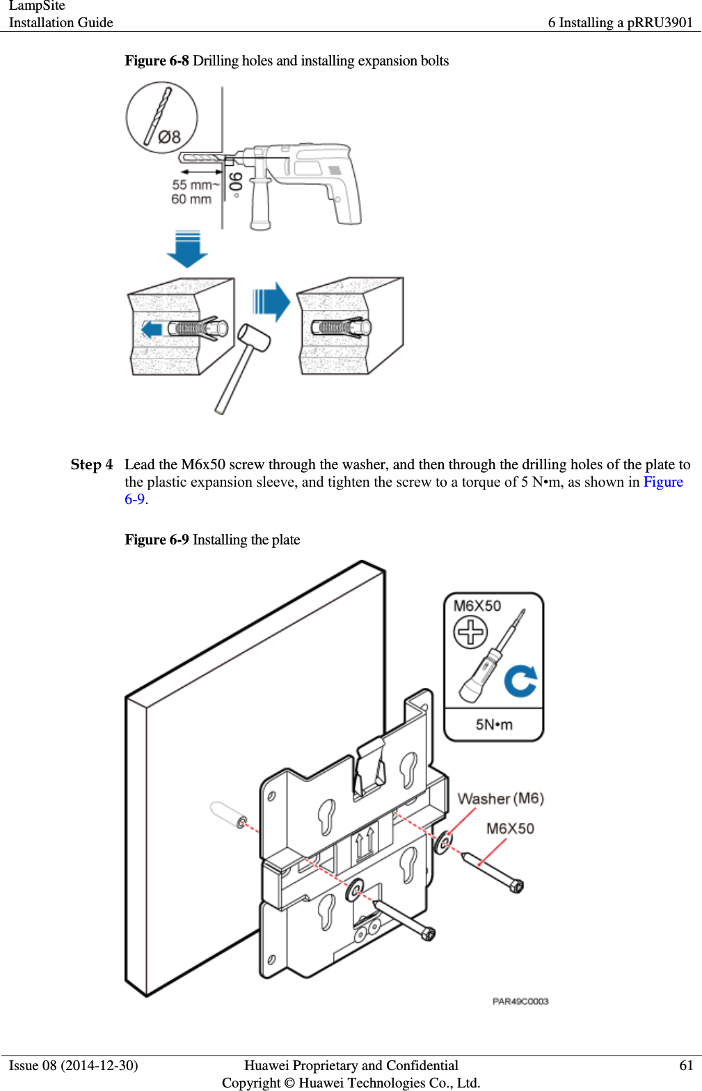
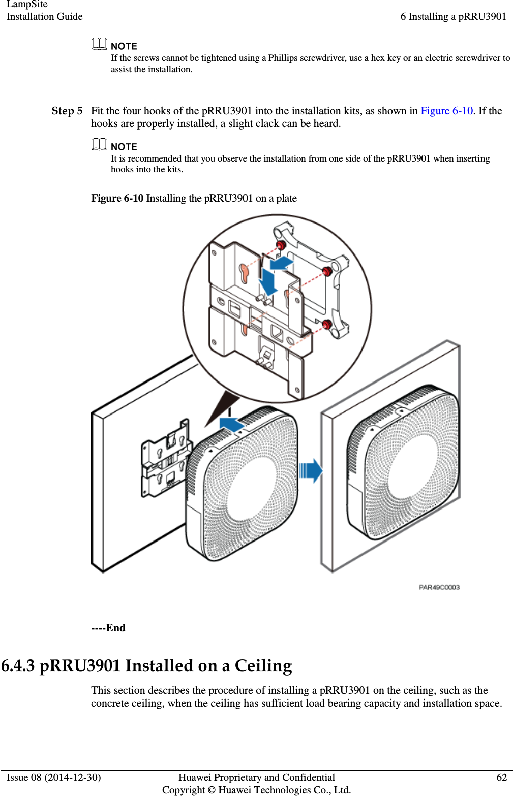
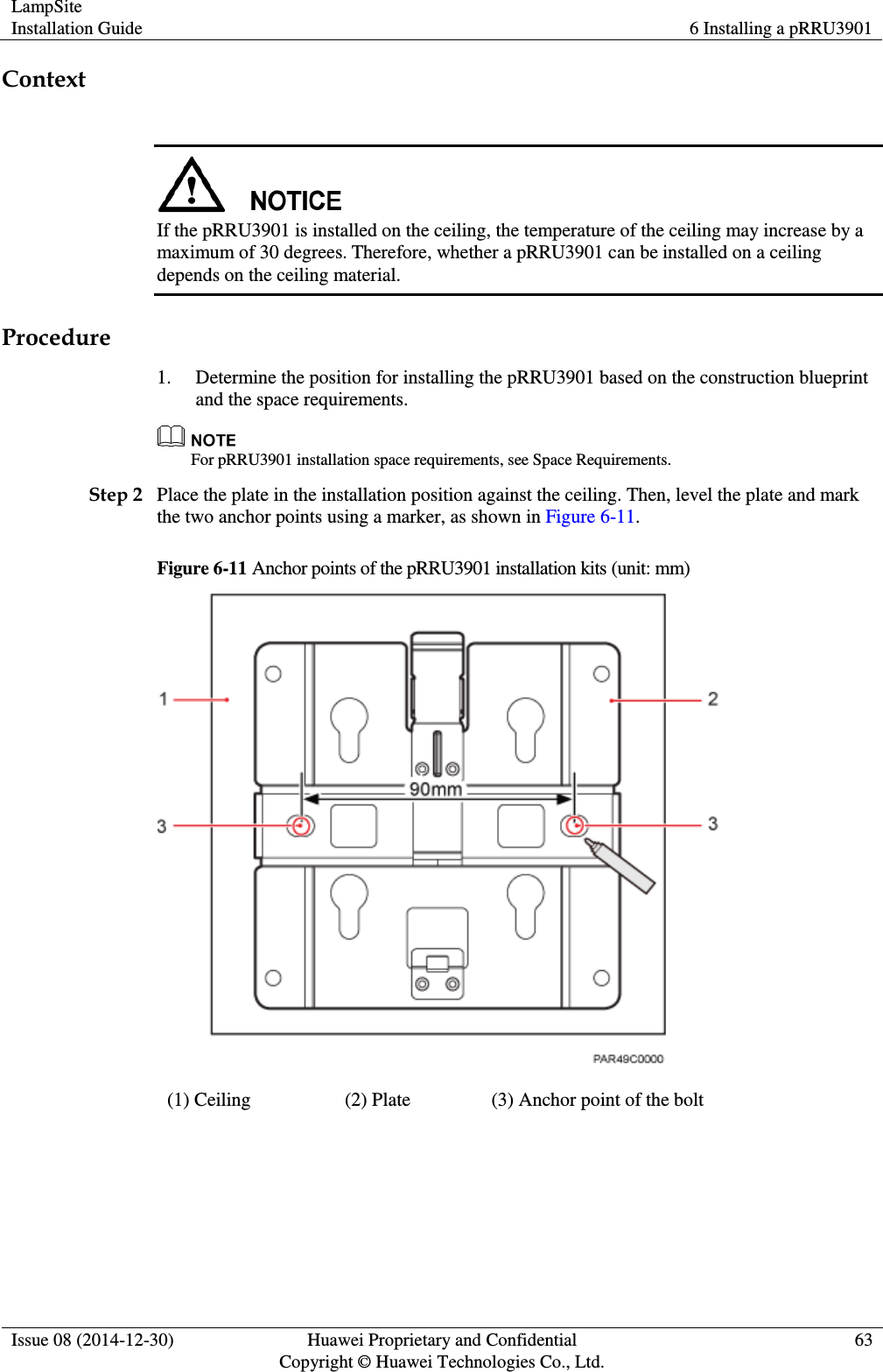
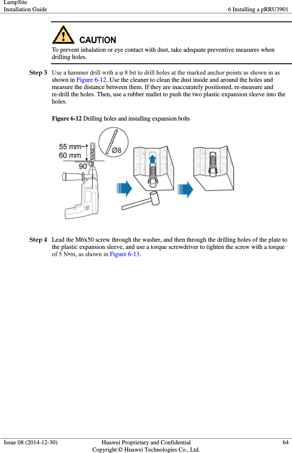
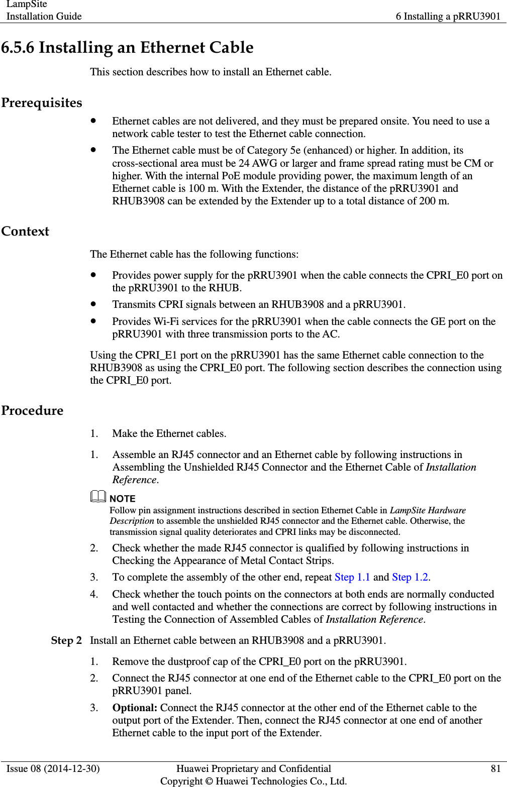
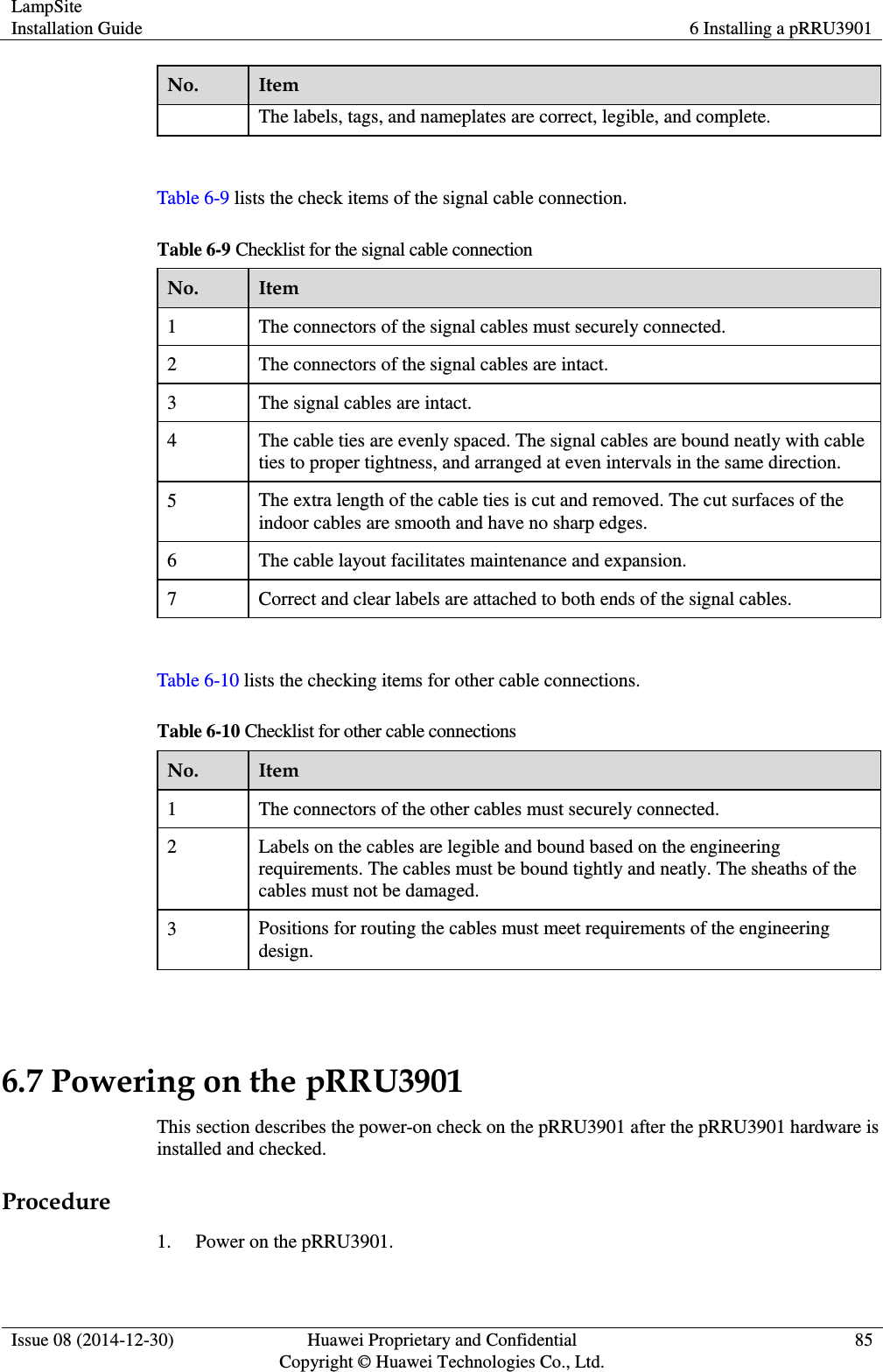
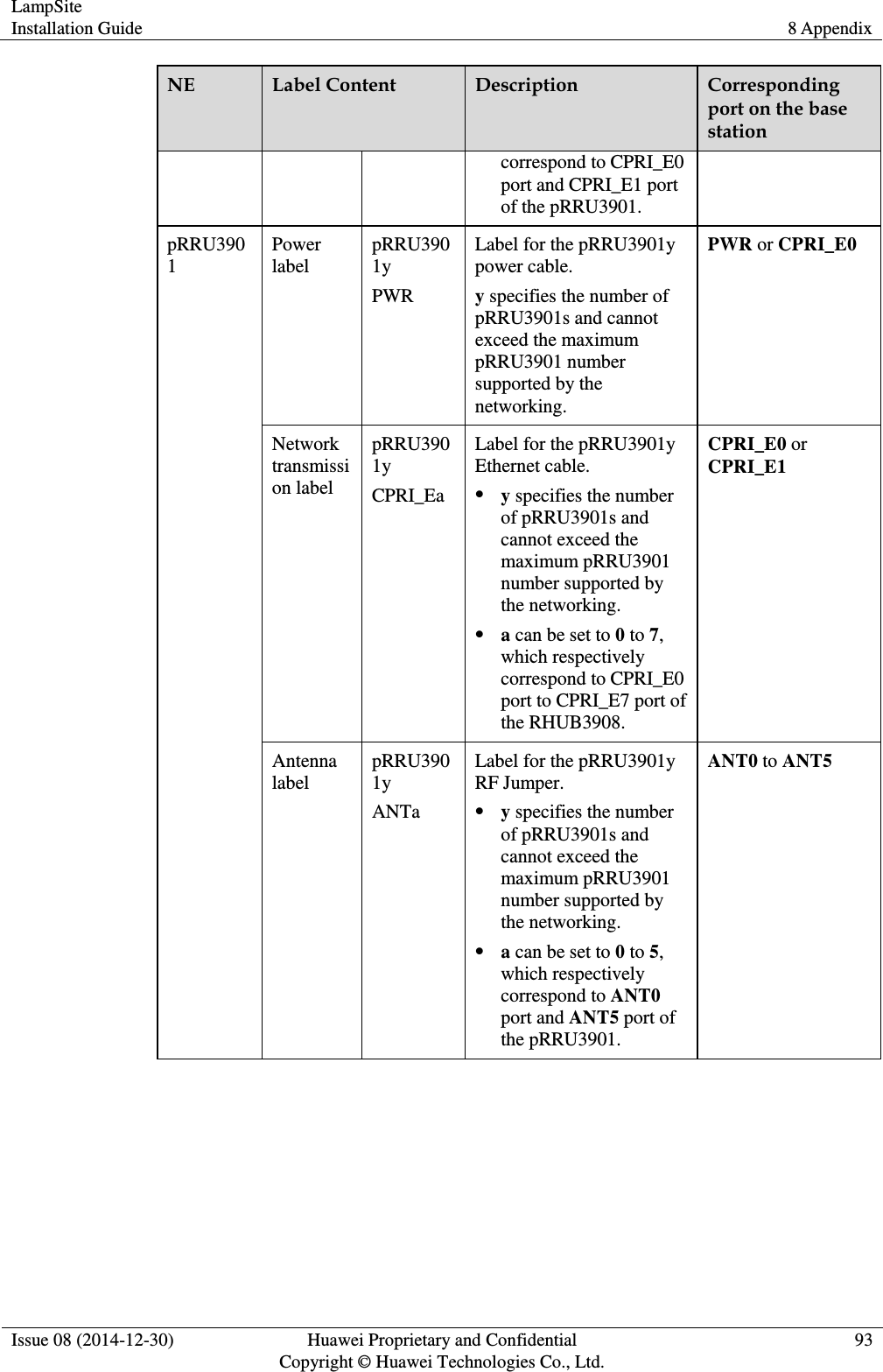
![LampSite Installation Guide 5 Installing an RHUB3908 Issue 08 (2014-12-30) Huawei Proprietary and Confidential Copyright © Huawei Technologies Co., Ltd. 34 If optical cables need to be routed close to a device on the tower, the optical cables are secured to the guard rail or pole with cable clips and the device cannot be far away from the position for securing the optical cables. If the optical cable close to a device on the tower is too long, the optical cables are wrapped and secured to the tower. 5.4.2 RHUB3908 Cable List This section describes the connector types and connections of the RHUB3908 cables. Table 5-2 lists RHUB3908 cables. Table 5-2 RHUB3908 cable list Cable One End The Other End Connector Connected to... Connector Connected to... PGND cable OT terminal (M4, 6 mm2 [0.009 in.2]) Ground screws on the RHUB3908 OT terminal (M6, 6 mm2 [0.009 in.2]) Ground terminal on the external ground bar RHUB3908 Power Supply Cable C13 female connector AC power input socket on the RHUB3908 3-pin connector External power input socket CPRI Optical Fiber DLC connector CPRI port on the LBBP, WBBP or UBBP in the BBU DLC connector CPRI0 or CPRI1 port on the RHUB3908 CPRI0 or CPRI1 port on the RHUB3908 DLC connector CPRI0 or CPRI1 port on the RHUB3908 CPRI port on the LBBP, WBBP or UBBP in the BBU FC connector, SC connector, or LC connector ODF CPRI0 or CPRI1 port on the RHUB3908 FC connector, SC connector, or LC connector ODF Ethernet Cable RJ45 connector CPRI_E0~CPRI_E7 port on the RHUB3908 RJ45 connector CPRI_E0~CPRI_E1 port on the pRRU3901 (Optional) RHUB3908 RJ45 connector EXT_ALM port on the Bare end Alarm signal port of the monitored](https://usermanual.wiki/Huawei-Technologies/PRU01B04.Host-Manual/User-Guide-2510796-Page-39.png)
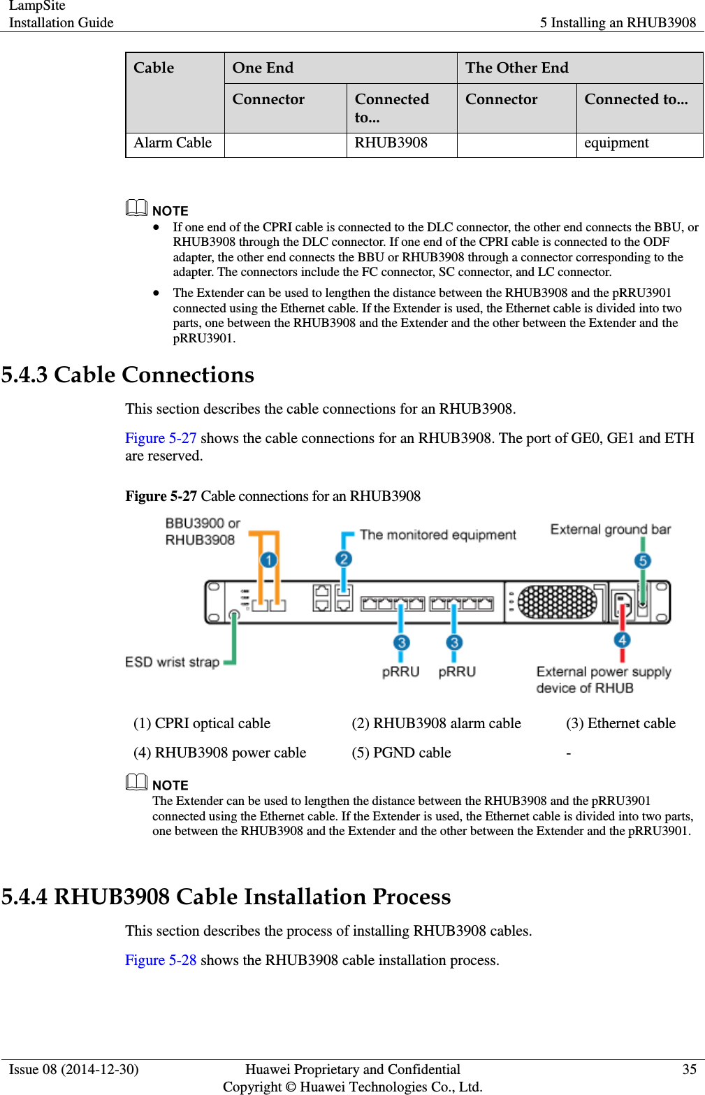
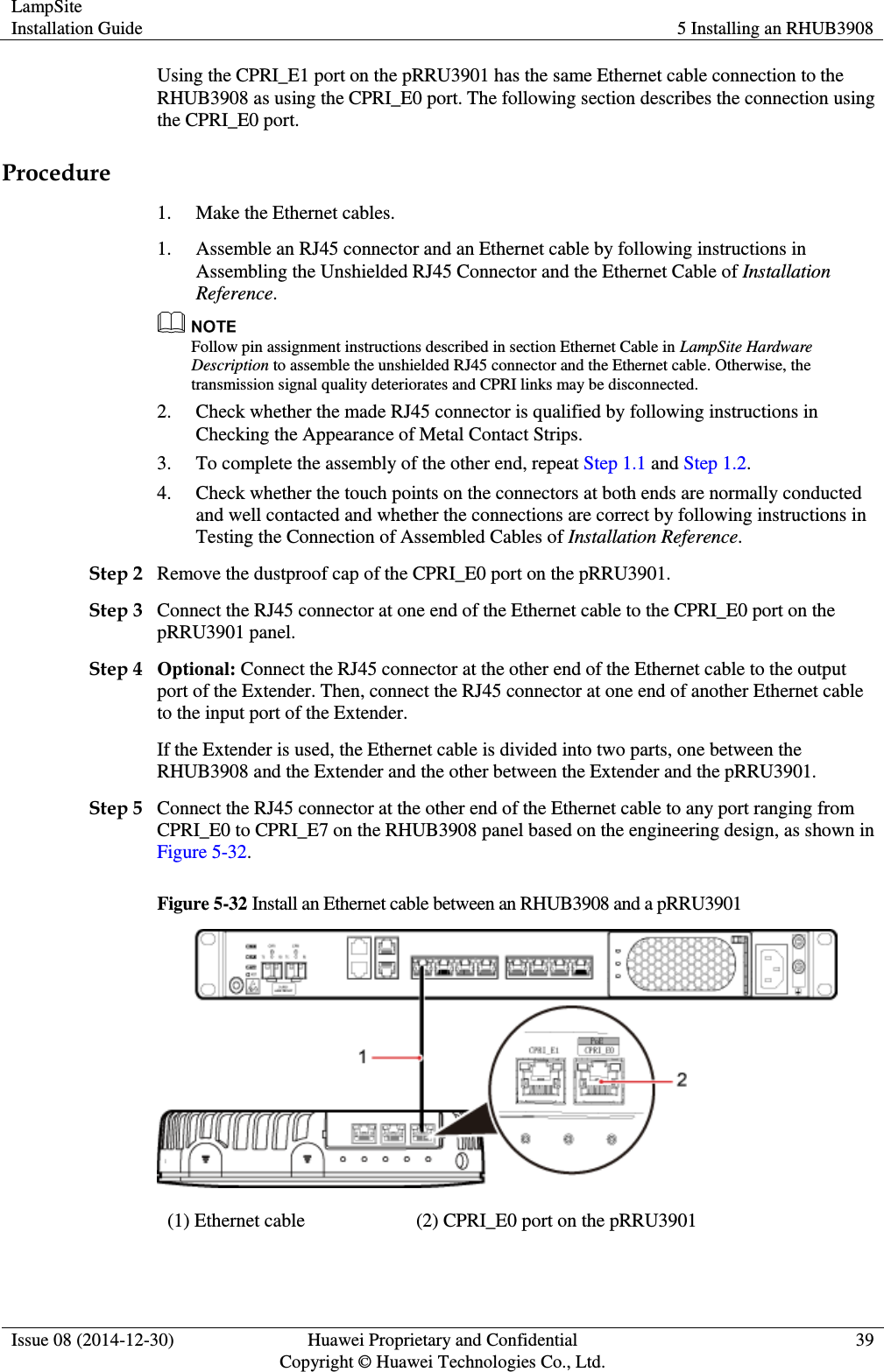
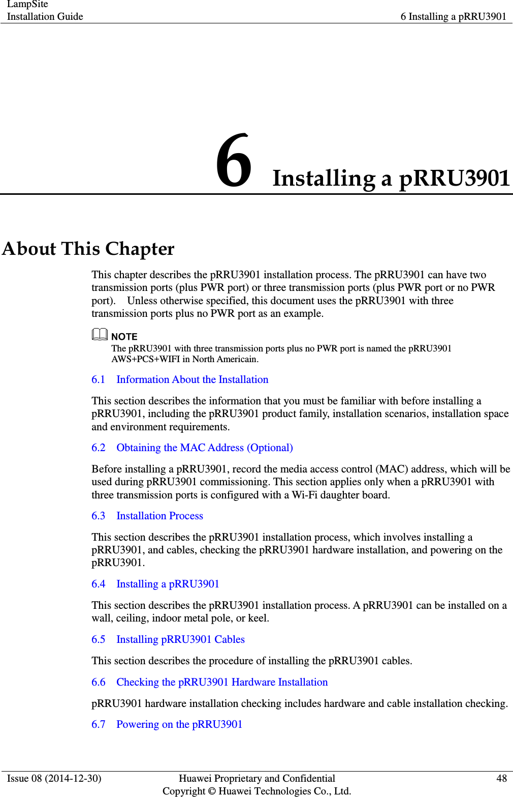
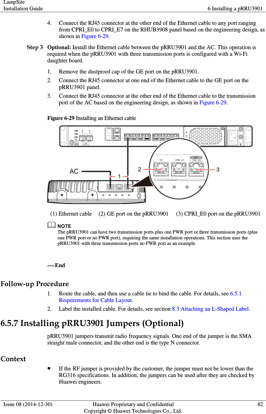
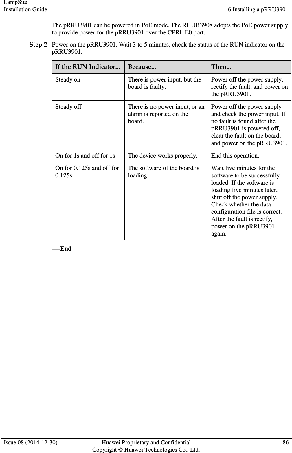
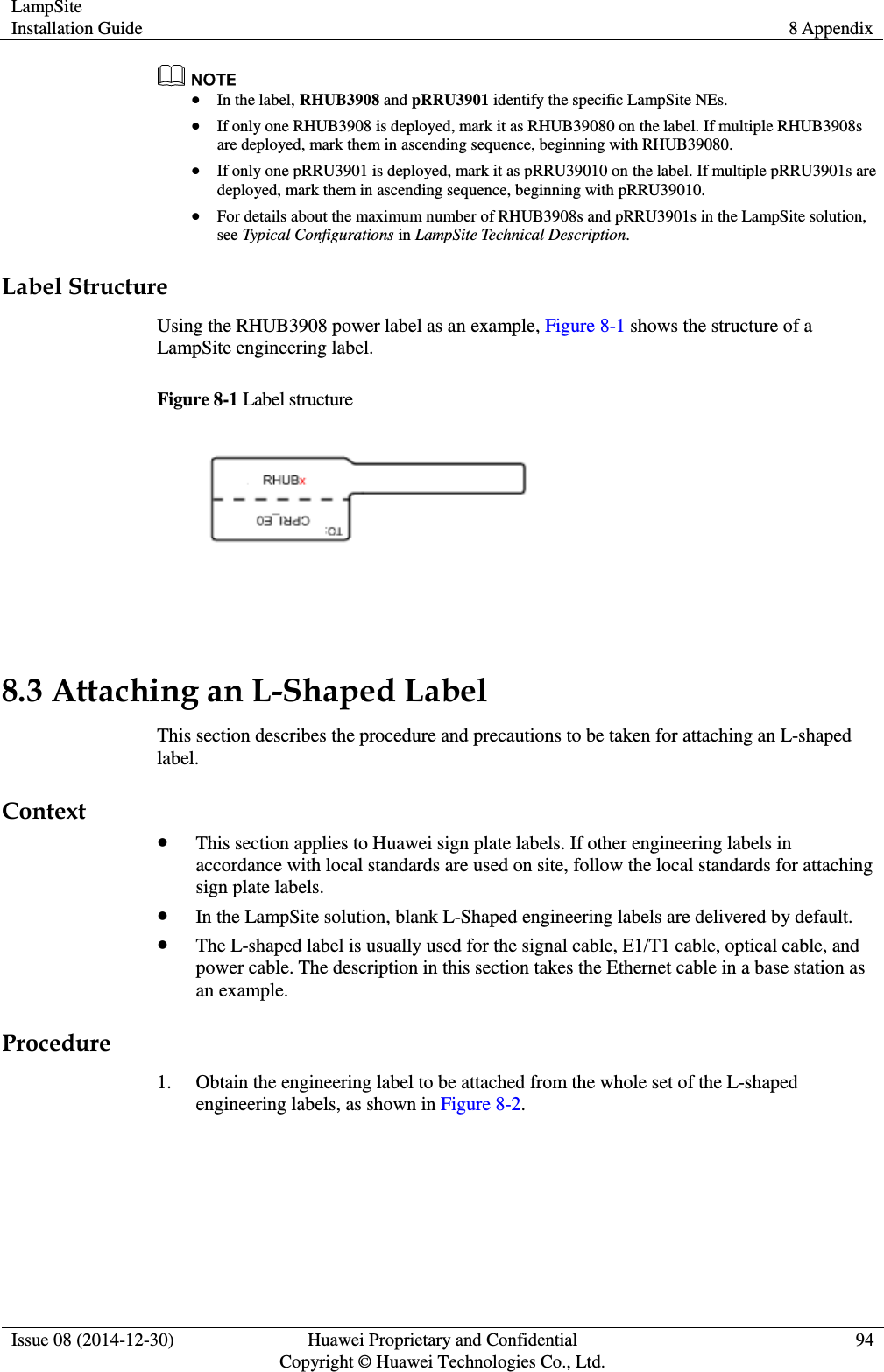
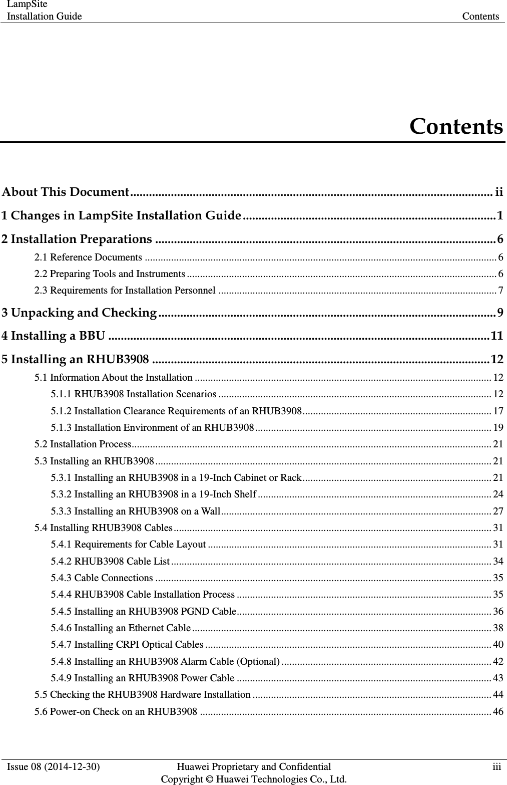
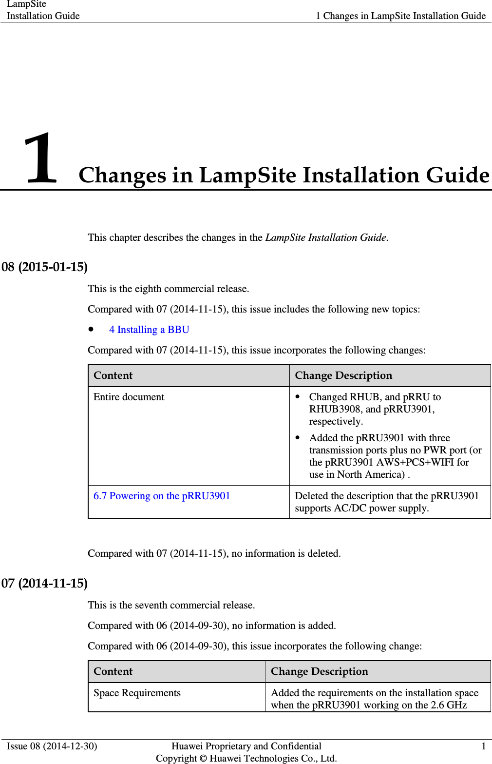
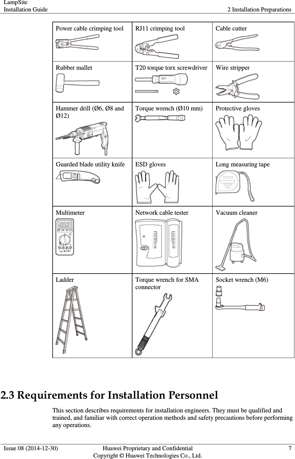
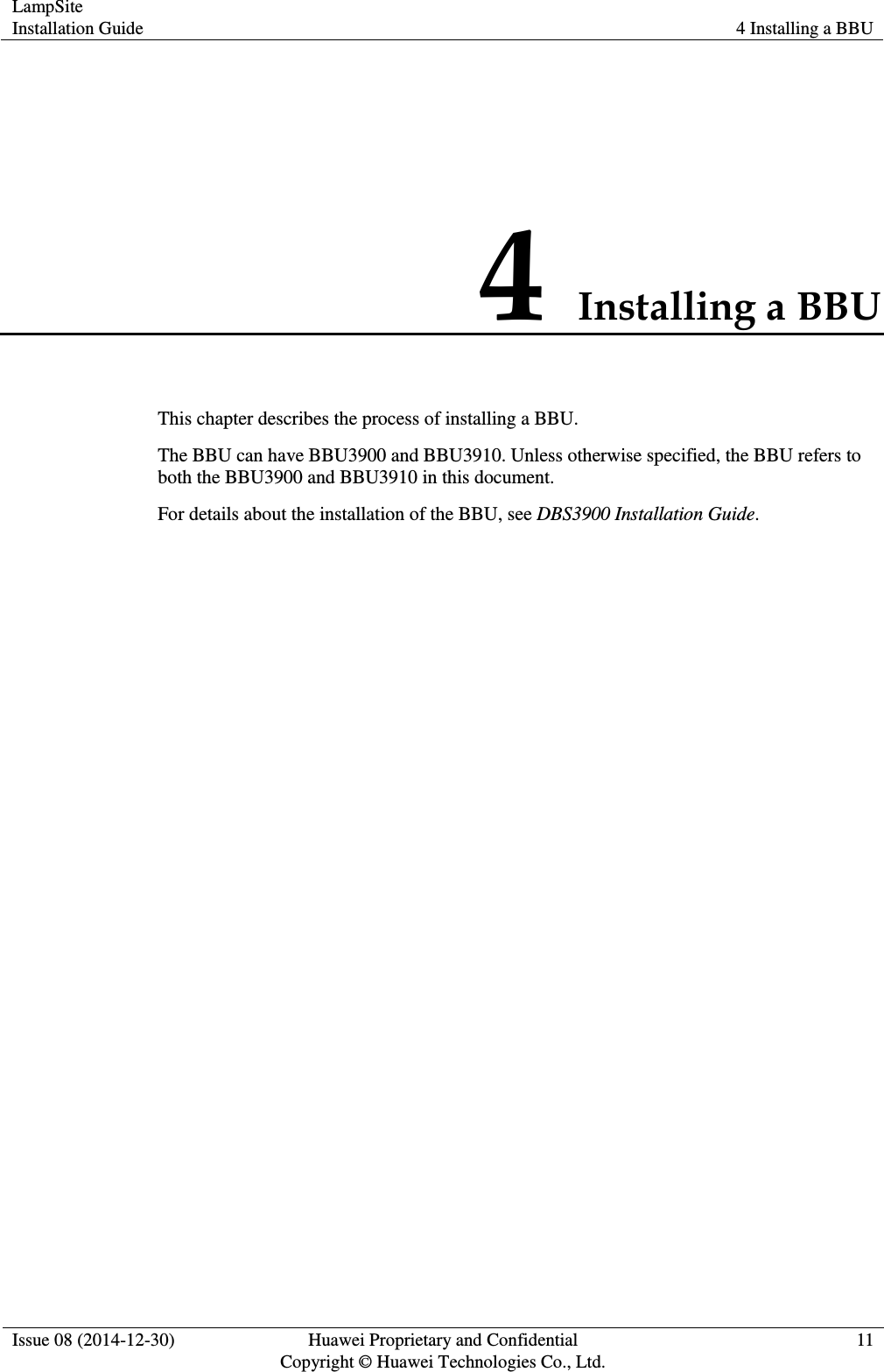
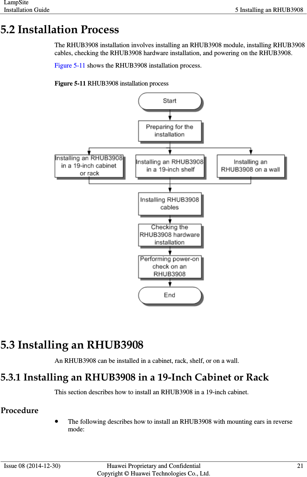
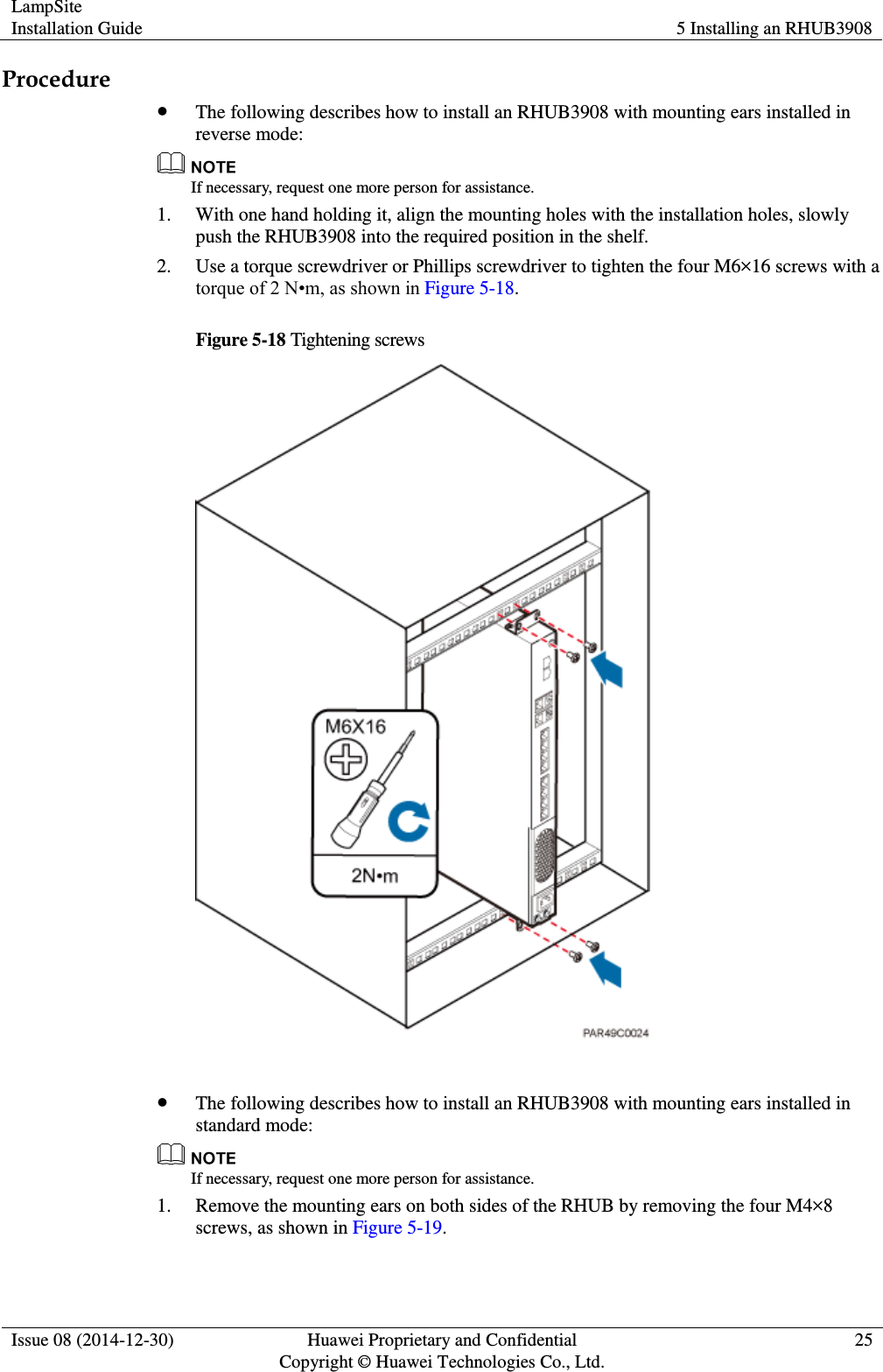
![LampSite Installation Guide 5 Installing an RHUB3908 Issue 08 (2014-12-30) Huawei Proprietary and Confidential Copyright © Huawei Technologies Co., Ltd. 36 Figure 5-28 RHUB3908 cable installation process 5.4.5 Installing an RHUB3908 PGND Cable An RHUB3908 PGND cable ensures proper grounding of an RHUB3908. Prerequisites The OT terminals at both ends of the PGND cable are prepared. Context The yellow and green or green PGND cable is a single cable. The cross-sectional area of the PGND cable is 6 mm2 (0.009 in.2). Both ends of the cable are OT terminals, as shown in Figure 1. Figure 5-29 Exterior of a PGND cable (1) OT terminal (6 mm2 [0.009 in.2], M4) (2) OT terminal (6 mm2 [0.009 in.2], M6)](https://usermanual.wiki/Huawei-Technologies/PRU01B04.Host-Manual/User-Guide-2510796-Page-41.png)