Huawei Technologies PRU01B04 pRRU Multi-Mode Radio Unit User Manual Installation Guide
Huawei Technologies Co.,Ltd pRRU Multi-Mode Radio Unit Installation Guide
Contents
- 1. Host Manual
- 2. Regulatory Compliance Statement
Host Manual

LampSite
Installation Guide
Issue
08
Date
2014-12-30
HUAWEI TECHNOLOGIES CO., LTD.

Issue 08 (2014-12-30)
Huawei Proprietary and Confidential
Copyright © Huawei Technologies Co., Ltd.
i
Copyright © Huawei Technologies Co., Ltd. 2014. All rights reserved.
No part of this document may be reproduced or transmitted in any form or by any means without prior
written consent of Huawei Technologies Co., Ltd.
Trademarks and Permissions
and other Huawei trademarks are trademarks of Huawei Technologies Co., Ltd.
All other trademarks and trade names mentioned in this document are the property of their respective
holders.
Notice
The purchased products, services and features are stipulated by the contract made between Huawei and
the customer. All or part of the products, services and features described in this document may not be
within the purchase scope or the usage scope. Unless otherwise specified in the contract, all statements,
information, and recommendations in this document are provided "AS IS" without warranties, guarantees or
representations of any kind, either express or implied.
The information in this document is subject to change without notice. Every effort has been made in the
preparation of this document to ensure accuracy of the contents, but all statements, information, and
recommendations in this document do not constitute a warranty of any kind, express or implied.
Huawei Technologies Co., Ltd.
Address:
Huawei Industrial Base
Bantian, Longgang
Shenzhen 518129
People's Republic of China
Website:
http://www.huawei.com
Email:
support@huawei.com
LampSite
Installation Guide
About This Document
Issue 08 (2014-12-30)
Huawei Proprietary and Confidential
Copyright © Huawei Technologies Co., Ltd.
ii
About This Document
Overview
This document describes how to install the modules and cables for the RHUB3908,
pRRU3901 indoors. It also provides checklists for hardware installation.
Product Version
The following table lists the product version related to this document.
Product Name
Solution Version
Product Version
DBS3900
SRAN9.0 and later versions
RAN16.0 and later versions
eRAN7.0 and later versions
eRAN TDD 7.0 and later
versions
V100R009C00 and later
versions
Intended Audience
This document is intended for:
BTS installation personnel

LampSite
Installation Guide
Contents
Issue 08 (2014-12-30)
Huawei Proprietary and Confidential
Copyright © Huawei Technologies Co., Ltd.
iii
Contents
About This Document .................................................................................................................... ii
1 Changes in LampSite Installation Guide ................................................................................. 1
2 Installation Preparations ............................................................................................................. 6
2.1 Reference Documents ...................................................................................................................................... 6
2.2 Preparing Tools and Instruments ...................................................................................................................... 6
2.3 Requirements for Installation Personnel .......................................................................................................... 7
3 Unpacking and Checking ............................................................................................................ 9
4 Installing a BBU .......................................................................................................................... 11
5 Installing an RHUB3908 ............................................................................................................ 12
5.1 Information About the Installation ................................................................................................................. 12
5.1.1 RHUB3908 Installation Scenarios ........................................................................................................ 12
5.1.2 Installation Clearance Requirements of an RHUB3908 ........................................................................ 17
5.1.3 Installation Environment of an RHUB3908 .......................................................................................... 19
5.2 Installation Process ......................................................................................................................................... 21
5.3 Installing an RHUB3908 ................................................................................................................................ 21
5.3.1 Installing an RHUB3908 in a 19-Inch Cabinet or Rack ........................................................................ 21
5.3.2 Installing an RHUB3908 in a 19-Inch Shelf ......................................................................................... 24
5.3.3 Installing an RHUB3908 on a Wall ....................................................................................................... 27
5.4 Installing RHUB3908 Cables ......................................................................................................................... 31
5.4.1 Requirements for Cable Layout ............................................................................................................ 31
5.4.2 RHUB3908 Cable List .......................................................................................................................... 34
5.4.3 Cable Connections ................................................................................................................................ 35
5.4.4 RHUB3908 Cable Installation Process ................................................................................................. 35
5.4.5 Installing an RHUB3908 PGND Cable ................................................................................................. 36
5.4.6 Installing an Ethernet Cable .................................................................................................................. 38
5.4.7 Installing CRPI Optical Cables ............................................................................................................. 40
5.4.8 Installing an RHUB3908 Alarm Cable (Optional) ................................................................................ 42
5.4.9 Installing an RHUB3908 Power Cable ................................................................................................. 43
5.5 Checking the RHUB3908 Hardware Installation ........................................................................................... 44
5.6 Power-on Check on an RHUB3908 ............................................................................................................... 46

LampSite
Installation Guide
Contents
Issue 08 (2014-12-30)
Huawei Proprietary and Confidential
Copyright © Huawei Technologies Co., Ltd.
iv
6 Installing a pRRU3901................................................................................................................ 48
6.1 Information About the Installation ................................................................................................................. 49
6.1.1 pRRU3901 Product Family ................................................................................................................... 49
6.1.2 pRRU3901 Installation Scenario........................................................................................................... 49
6.1.3 Space Requirements .............................................................................................................................. 53
6.1.4 pRRU3901 Installation Environment Requirements ............................................................................. 54
6.2 Obtaining the MAC Address (Optional)......................................................................................................... 55
6.3 Installation Process ......................................................................................................................................... 56
6.4 Installing a pRRU3901 ................................................................................................................................... 57
6.4.1 pRRU3901 Installation Kits .................................................................................................................. 58
6.4.2 pRRU3901 Installed on a Wall .............................................................................................................. 59
6.4.3 pRRU3901 Installed on a Ceiling ......................................................................................................... 62
6.4.4 pRRU3901 Installed on a Pole .............................................................................................................. 66
6.4.5 pRRU3901 Installed on a Plate ............................................................................................................. 68
6.4.6 pRRU3901 Installed on a Keel ............................................................................................................. 71
6.5 Installing pRRU3901 Cables .......................................................................................................................... 74
6.5.1 Requirements for Cable Layout ............................................................................................................ 74
6.5.2 pRRU3901 Cable List ........................................................................................................................... 76
6.5.3 Cable Connections ................................................................................................................................ 76
6.5.4 Cable Connections (LTE TDD) ............................................................................................................. 79
6.5.5 pRRU3901 cable installation process ................................................................................................... 80
6.5.6 Installing an Ethernet Cable .................................................................................................................. 81
6.5.7 Installing pRRU3901 Jumpers (Optional)............................................................................................. 82
6.6 Checking the pRRU3901 Hardware Installation ............................................................................................ 84
6.7 Powering on the pRRU3901........................................................................................................................... 85
7 Installing the Extender (Optional) ........................................................................................... 87
8 Appendix ...................................................................................................................................... 90
8.1 MAC Collection Template ............................................................................................................................. 90
8.2 LampSite Engineering Label .......................................................................................................................... 91
8.3 Attaching an L-Shaped Label ......................................................................................................................... 94
8.4 Installing RF Daughter Boards on a pRRU3901 (in Capacity Expansion Scenarios) .................................... 96
LampSite
Installation Guide
1 Changes in LampSite Installation Guide
Issue 08 (2014-12-30)
Huawei Proprietary and Confidential
Copyright © Huawei Technologies Co., Ltd.
1
1 Changes in LampSite Installation Guide
This chapter describes the changes in the LampSite Installation Guide.
08 (2015-01-15)
This is the eighth commercial release.
Compared with 07 (2014-11-15), this issue includes the following new topics:
4 Installing a BBU
Compared with 07 (2014-11-15), this issue incorporates the following changes:
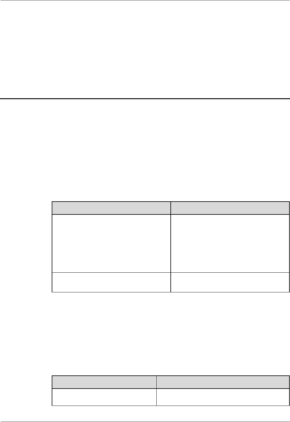
Content
Change Description
Entire document
Changed RHUB, and pRRU to
RHUB3908, and pRRU3901,
respectively.
Added the pRRU3901 with three
transmission ports plus no PWR port (or
the pRRU3901 AWS+PCS+WIFI for
use in North America) .
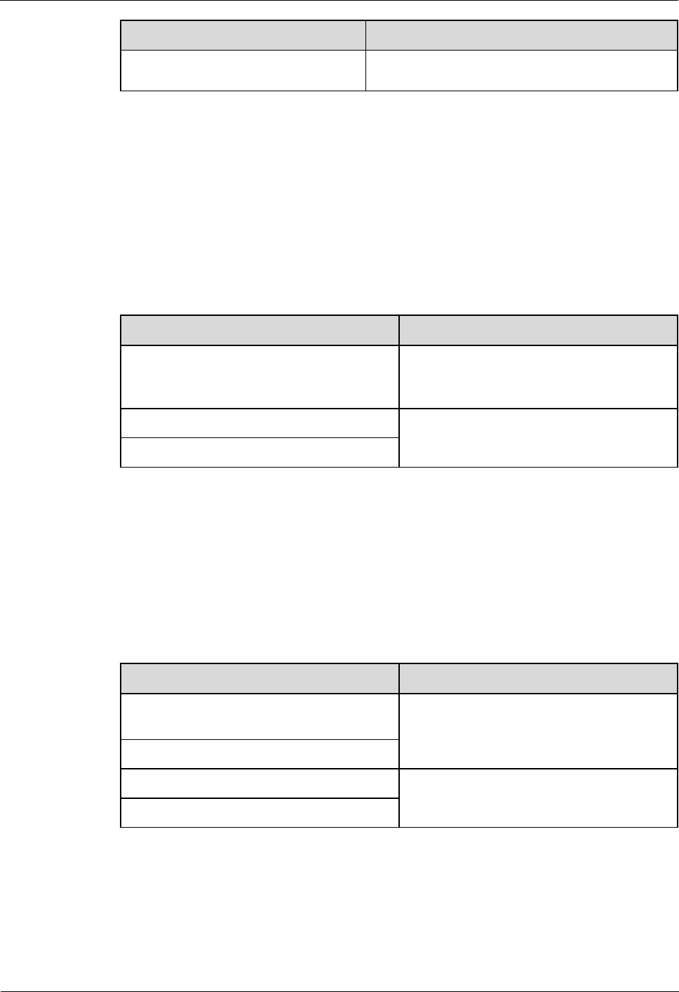
6.7 Powering on the pRRU3901
Deleted the description that the pRRU3901
supports AC/DC power supply.
Compared with 07 (2014-11-15), no information is deleted.
07 (2014-11-15)
This is the seventh commercial release.
Compared with 06 (2014-09-30), no information is added.
Compared with 06 (2014-09-30), this issue incorporates the following change:
Content
Change Description
Space Requirements
Added the requirements on the installation space
when the pRRU3901 working on the 2.6 GHz
LampSite
Installation Guide
1 Changes in LampSite Installation Guide
Issue 08 (2014-12-30)
Huawei Proprietary and Confidential
Copyright © Huawei Technologies Co., Ltd.
2
Content
Change Description
band and the Wi-Fi module need to process
services concurrently.
Compared with 06 (2014-09-30), this issue excludes the following topic:
Installing RF Daughter Boards on a pRRU3901 (in Capacity Expansion Scenarios)
06 (2014-09-30)
This is the sixth commercial release.
Compared with 05 (2014-08-30), no information is added.
Compared with 05 (2014-08-30), this issue incorporates the following changes:
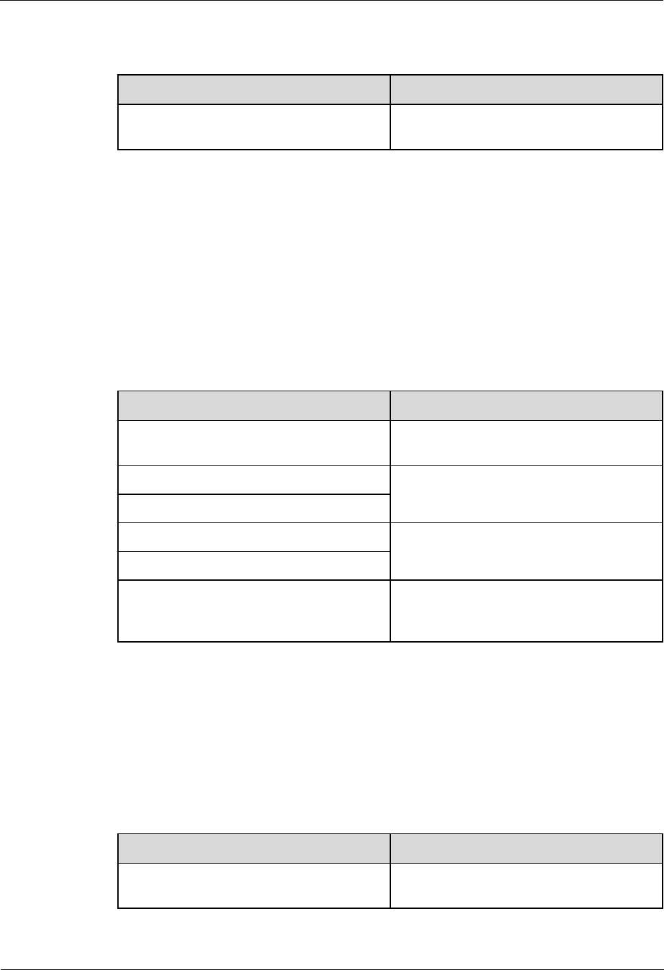
Content
Change Description
pRRU Installation Environment
Requirements
Changed the operating temperature of
pRRU3901s to a range from - 5°C to +
40°C.
Requirements for Cable Layout
Added the cabling requirements for Ethernet
cables.
Requirements for Cable Layout
Compared with 05 (2014-08-30), no information is deleted.
05 (2014-08-30)
This is the fifth commercial release.
Compared with 04 (2014-07-30), no information is added.
Compared with 04 (2014-07-30), this issue incorporates the following changes:
Content
Change Description
Installation Clearance Requirements of an
RHUB
Added the security precautions for the
RHUB3908 installation environment.
Requirements for Cable Layout
Installing an Ethernet Cable
Added the Ethernet cable specifications and
requirements on flame spread rating.
Installing an Ethernet Cable
Compared with 04 (2014-07-30), no information is deleted.
04 (2014-07-30)
This is the fourth commercial release.
LampSite
Installation Guide
1 Changes in LampSite Installation Guide
Issue 08 (2014-12-30)
Huawei Proprietary and Confidential
Copyright © Huawei Technologies Co., Ltd.
3
Compared with 03 (2014-06-30), no information is added.
Compared with 03 (2014-06-30), this issue incorporates the following change:
Content
Change Description
7 Installing the Extender (Optional)
Added the descriptions about installing a
Extender on a Ceiling.
Compared with 03 (2014-06-30), no information is deleted.
03 (2014-06-30)
This is the third commercial release.
Compared with 02 (2014-05-30), this issue includes the following new topics:
8.2 LampSite Engineering Label
8.3 Attaching an L-Shaped Label
Compared with 02 (2014-05-30), this issue incorporates the following changes:
Content
Change Description
Cable Connections
Modified the description about cable
connections of the RHUB3908.
Installing RHUB Cables
Added the steps for attaching labels to
cables.
Installing pRRU Cables
Installing an Ethernet Cable
Added the steps for making Ethernet cables.
Installing an Ethernet Cable
Installing RF Daughter Boards on a
pRRU3901 (in Capacity Expansion
Scenarios)
Added the descriptions about the supported
block type.
Compared with 02 (2014-05-30), no information is deleted.
02 (2014-05-30)
This is the second commercial release.
Compared with 01 (2014-04-26), no information is added.
Compared with 01 (2014-04-26), this issue incorporates the following change:
Content
Change Description
Entire document
Added the descriptions about the LTE
FDD+LTE FDD mode.
LampSite
Installation Guide
1 Changes in LampSite Installation Guide
Issue 08 (2014-12-30)
Huawei Proprietary and Confidential
Copyright © Huawei Technologies Co., Ltd.
4
Compared with 01 (2014-04-26), no information is deleted.
01 (2014-04-26)
This is the first commercial release.
Compared with Draft C (2014-03-26), no information is added.
Compared with Draft C (2014-03-26), this issue incorporates the following change:
Content
Change Description
Entire document
Changed the pRRU3901 name from
pRRU3901 with two Ethernet ports to
pRRU3901 with two transmission ports, and
pRRU3901 with three Ethernet ports to
pRRU3901 with three transmission ports.
Compared with Draft C (2014-03-26), no information is deleted.
Draft C (2014-03-26)
This is a draft release.
Compared with Draft B (2014-02-28), no information is added.
Compared with Draft B (2014-02-28), this issue incorporates the following changes:
Content
Change Description
Installing CRPI Optical Cables
Added the description of connecting the
CPRI cable to the TX and RX ports of the
optical module crossly.
pRRU Installation Environment
Requirements
The operating temperature of pRRU3901 is
updated.
Compared with Draft B (2014-02-28), no information is deleted.
Draft B (2014-02-28)
This is a draft release.
Compared with draft A (2013-11-30), this issue includes the following new topics:
Obtaining the MAC Address (Optional)
Cable Connections
MAC Collection Template
Compared with draft A (2013-11-30), this issue incorporates the following changes:
Content
Change Description
Entire document
Added descriptions about pRRU3901s with

LampSite
Installation Guide
1 Changes in LampSite Installation Guide
Issue 08 (2014-12-30)
Huawei Proprietary and Confidential
Copyright © Huawei Technologies Co., Ltd.
5
Content
Change Description
three transmission ports. Such pRRU3901s
support integrated Wi-Fi services.
Added the descriptions about the UMTS,
LTE FDD and UMTS+LTE FDD mode.
LampSite Installation Guide
Optimized descriptions about matching
product versions.
Installing an Ethernet Cable
Changed the cable name from
RHUB3908-pRRU3901 Ethernet cable to
Ethernet cable.
Installing an Ethernet Cable
Compared with draft A (2013-11-30), this issue excludes the following topics:
Installing External Antennas (Optional)
RHUB3908 Exterior
RHUB3908 Ports and Indicators
pRRU3901 Exterior
pRRU3901 Ports and Indicators
Draft A (2013-11-30)
This is a draft release.
LampSite
Installation Guide
2 Installation Preparations
Issue 08 (2014-12-30)
Huawei Proprietary and Confidential
Copyright © Huawei Technologies Co., Ltd.
6
2 Installation Preparations
About This Chapter
Before starting the installation, you must obtain the required reference documents, tools, and
instruments, and familiarize yourself with the skills required.
2.1 Reference Documents
Before the installation, you must read the following documents:
2.2 Preparing Tools and Instruments
This section describes the tools and instruments that must be prepared before the installation.
2.3 Requirements for Installation Personnel
This section describes requirements for installation engineers. They must be qualified and
trained, and familiar with correct operation methods and safety precautions before performing
any operations.
2.1 Reference Documents
Before the installation, you must read the following documents:
LampSite Hardware Description
Installation Reference
For details about how to install a baseband unit (BBU), see DBS3900 Installation Guide.
2.2 Preparing Tools and Instruments
This section describes the tools and instruments that must be prepared before the installation.
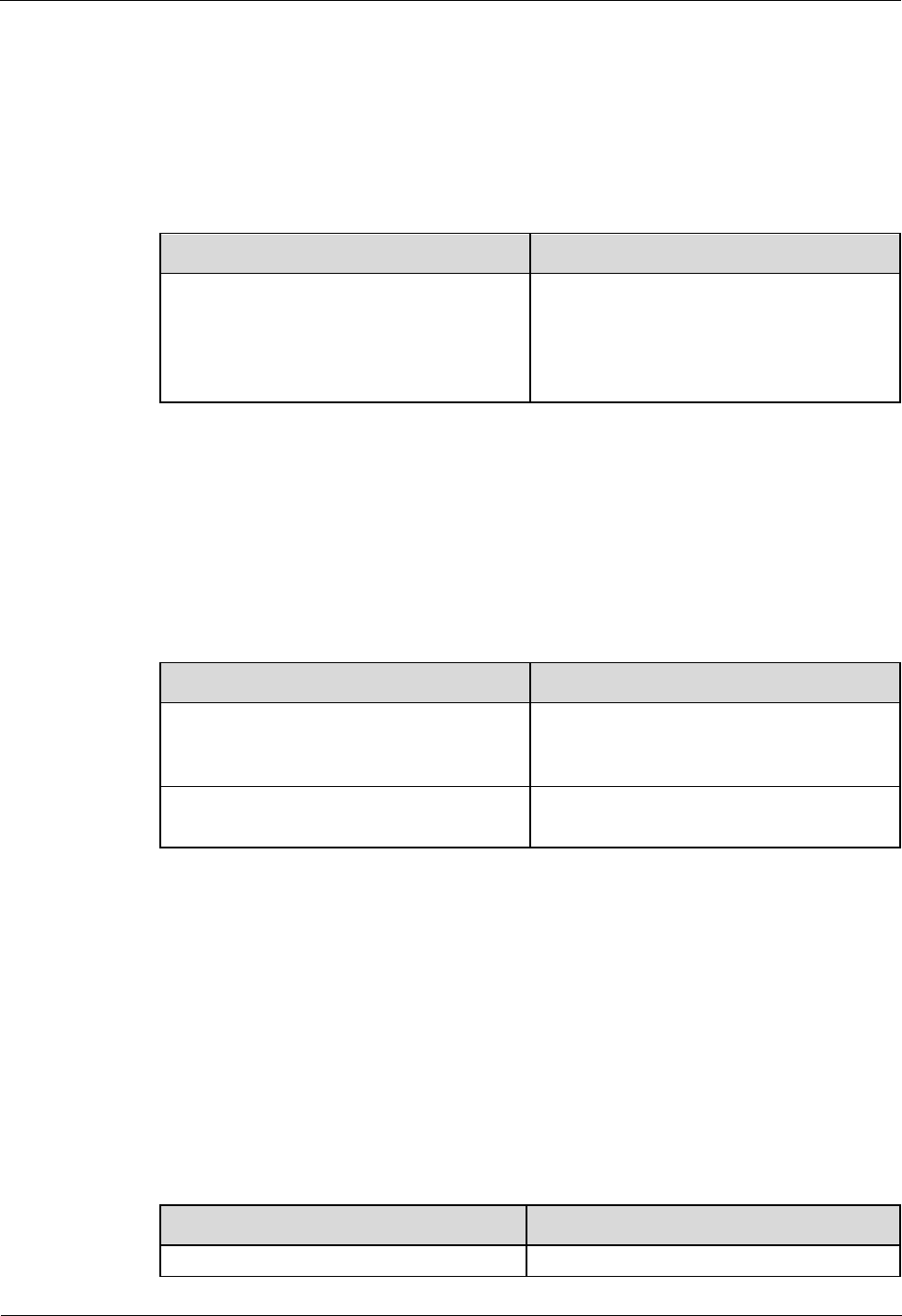
Marker
Level
Torque screwdriver
(M4 to M6)
Diagonal pliers
LampSite
Installation Guide
2 Installation Preparations
Issue 08 (2014-12-30)
Huawei Proprietary and Confidential
Copyright © Huawei Technologies Co., Ltd.
7
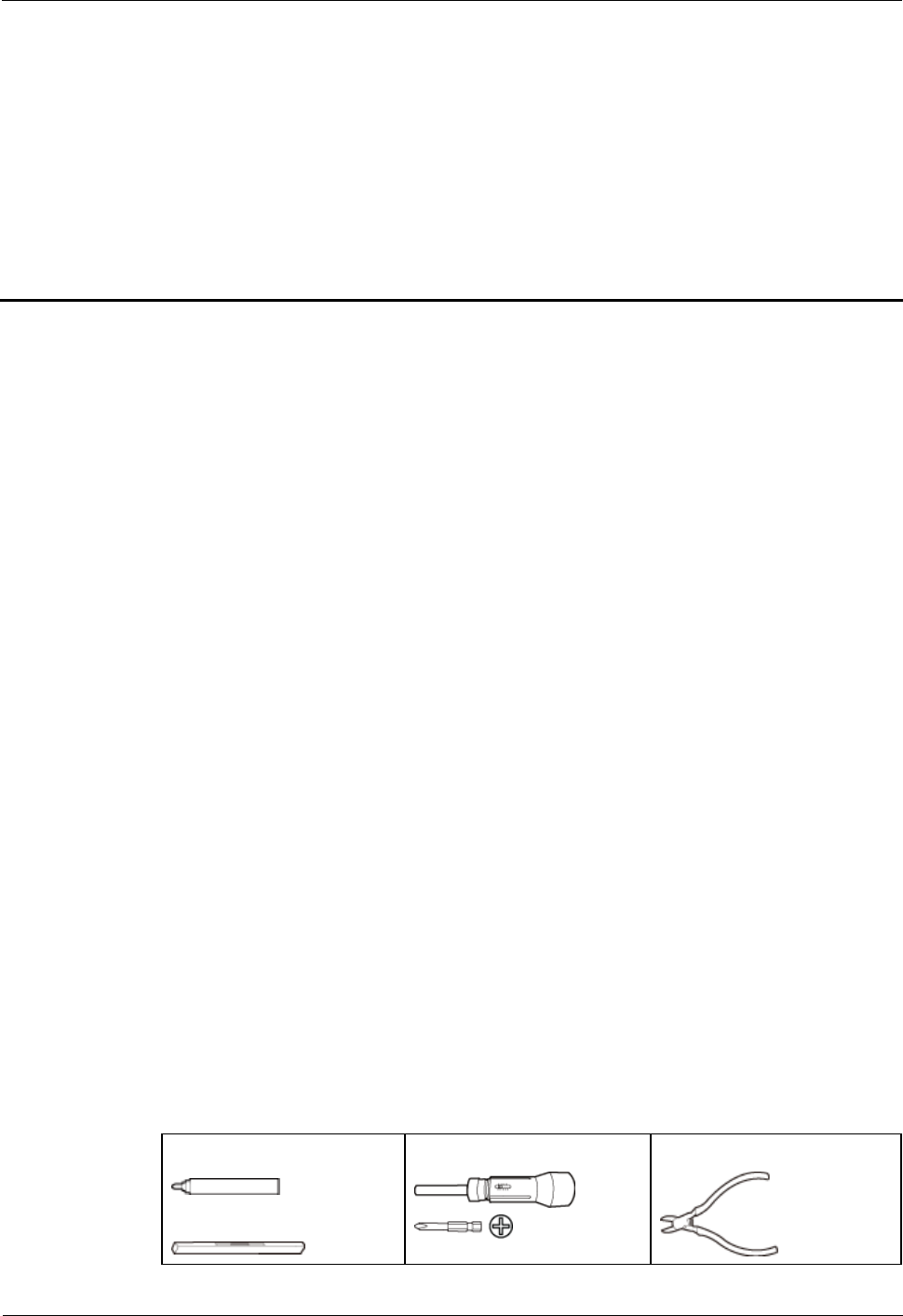
Power cable crimping tool
RJ11 crimping tool
Cable cutter
Rubber mallet
T20 torque torx screwdriver
Wire stripper
Hammer drill (Ø6, Ø8 and
Ø12)
Torque wrench (Ø10 mm)
Protective gloves
Guarded blade utility knife
ESD gloves
Long measuring tape
Multimeter
Network cable tester
Vacuum cleaner
Ladder
Torque wrench for SMA
connector
Socket wrench (M6)
2.3 Requirements for Installation Personnel
This section describes requirements for installation engineers. They must be qualified and
trained, and familiar with correct operation methods and safety precautions before performing
any operations.

LampSite
Installation Guide
2 Installation Preparations
Issue 08 (2014-12-30)
Huawei Proprietary and Confidential
Copyright © Huawei Technologies Co., Ltd.
8
Before the installation, pay attention to the following items:
Technical engineers must take Huawei training and be familiar with proper installation
and operation methods.
The number of installation personnel depends on the engineering schedule and
installation environment. Generally, three to five persons are required. Generally, only
three to five onsite personnel are necessary.

LampSite
Installation Guide
3 Unpacking and Checking
Issue 08 (2014-12-30)
Huawei Proprietary and Confidential
Copyright © Huawei Technologies Co., Ltd.
9
3 Unpacking and Checking
This section describes how to unpack and check the delivered equipment to ensure that the
materials are complete and intact.
Context
The following lists important notes when you are transporting, lifting, or installing the equipment or
components:
Protect them from colliding with doors, walls, shelves, or other objects.
Wear clean gloves and do not touch them with bare hands, sweat-soaked gloves, or dirty gloves.
You must power on the RHUB3908 or pRRU within 7 days after it is unpacked.
Procedure
1. Count the total number of the shipments.
If...
Then...
The total number of the components is
consistent with that recorded in the
packing lists on all packing boxes
Go to Step 2.
The total number of the components is
inconsistent with that recorded in the
packing lists on all packing boxes
Report the problems and causes to the local
Huawei office.
Step 2 Check the exterior of each packing box.
LampSite
Installation Guide
3 Unpacking and Checking
Issue 08 (2014-12-30)
Huawei Proprietary and Confidential
Copyright © Huawei Technologies Co., Ltd.
10
If...
Then...
The exterior of each packing box is
intact
Go to Step 3.
It is damaged or soaked
Report the problems and causes to the local
Huawei office.
The collision label is red
Do not unpack the packing box and claim
for compensation from the transportation
company.
Step 3 Check the type and quantity of the equipment in the boxes according to the packing list.
If...
Then...
The type and number are consistent
with the packing list on each packing
list
Sign the Packing List with the operator.
There is any shortage, wrong delivery,
or damaged equipment
Report the problems and causes to the local
Huawei office.
Perform the following operations to protect the components from any damages and help find
out the cause of any damage in future: 1. Store the unpacked equipment and packing materials
indoors. 2. Take photos of the storeroom, rusted or eroded equipment, packing box, and
packing materials. 3. File the photos.
----End

LampSite
Installation Guide
4 Installing a BBU
Issue 08 (2014-12-30)
Huawei Proprietary and Confidential
Copyright © Huawei Technologies Co., Ltd.
11
4 Installing a BBU
This chapter describes the process of installing a BBU.
The BBU can have BBU3900 and BBU3910. Unless otherwise specified, the BBU refers to
both the BBU3900 and BBU3910 in this document.
For details about the installation of the BBU, see DBS3900 Installation Guide.

LampSite
Installation Guide
5 Installing an RHUB3908
Issue 08 (2014-12-30)
Huawei Proprietary and Confidential
Copyright © Huawei Technologies Co., Ltd.
12
5 Installing an RHUB3908
About This Chapter
This chapter describes the process of installing an RHUB3908.
5.1 Information About the Installation
This section describes the information to be learnt before RHUB3908 installation, including
the RHUB3908 installation scenarios, clearance, and installation environment.
5.2 Installation Process
The RHUB3908 installation involves installing an RHUB3908 module, installing RHUB3908
cables, checking the RHUB3908 hardware installation, and powering on the RHUB3908.
5.3 Installing an RHUB3908
An RHUB3908 can be installed in a cabinet, rack, shelf, or on a wall.
5.4 Installing RHUB3908 Cables
This section describes how to install cables for an RHUB3908.
5.5 Checking the RHUB3908 Hardware Installation
After an RHUB3908 is installed, check the installation of hardware including the devices and
related cables.
5.6 Power-on Check on an RHUB3908
This section describes the power-on check on the RHUB3908 after the RHUB3908 hardware
is installed and checked.
5.1 Information About the Installation
This section describes the information to be learnt before RHUB3908 installation, including
the RHUB3908 installation scenarios, clearance, and installation environment.
5.1.1 RHUB3908 Installation Scenarios
An RHUB3908 can be installed in a 19-inch cabinet, rack, shelf, or on a wall.
LampSite
Installation Guide
5 Installing an RHUB3908
Issue 08 (2014-12-30)
Huawei Proprietary and Confidential
Copyright © Huawei Technologies Co., Ltd.
13
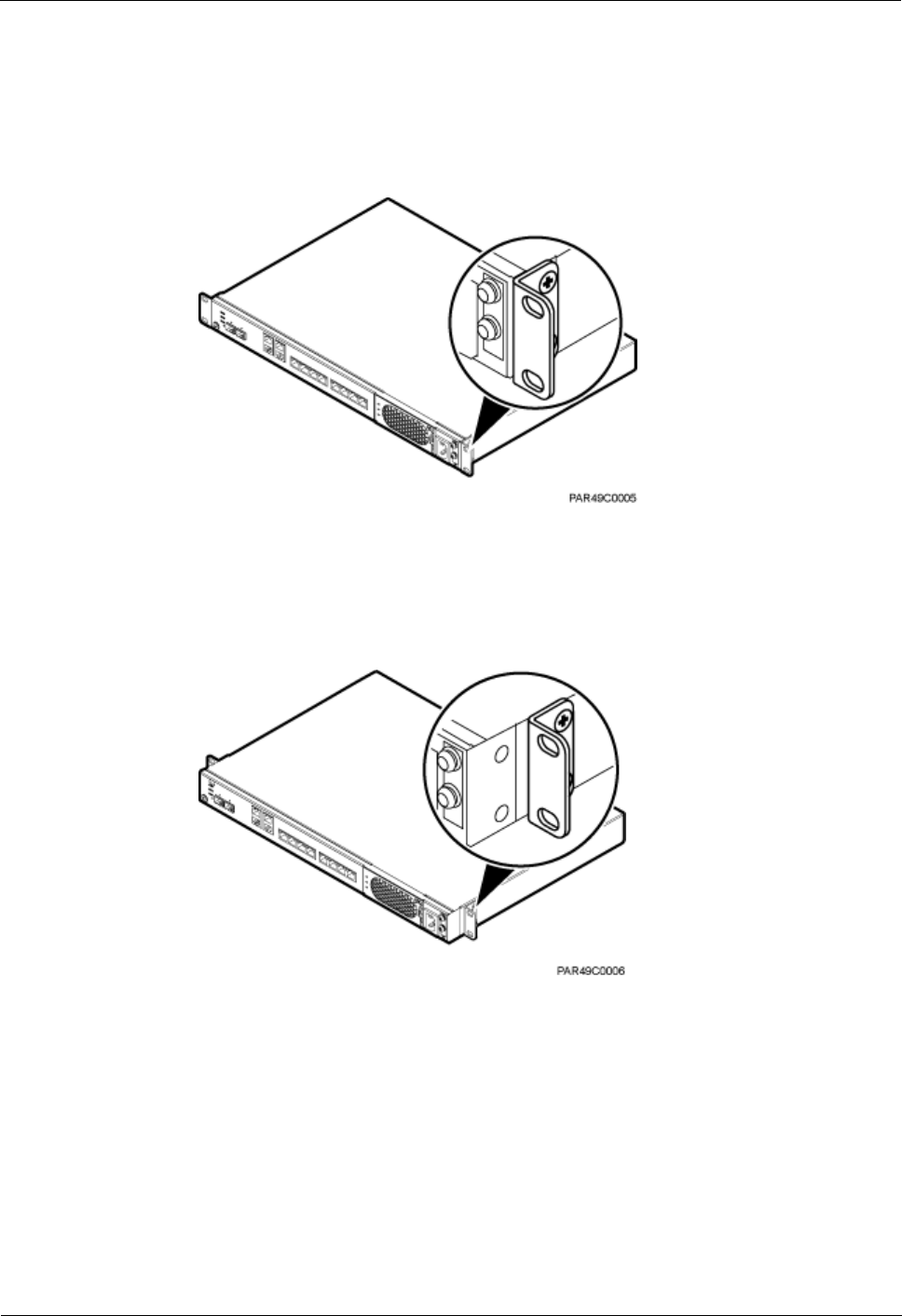
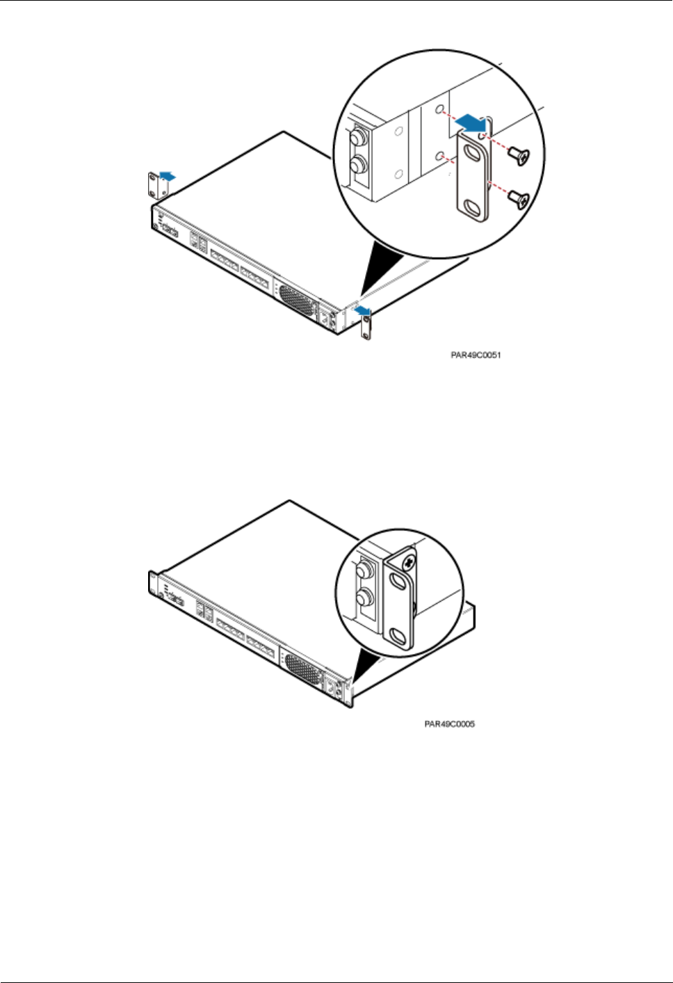
The RHUB3908 supports that mounting ears are installed in standard mode or reverse mode.
The reverse mode is used by default. The two installation modes are defined as follows:
In standard mode, the front of the mounting ear is aligned with the RHUB3908 panel, as
shown in Figure 5-1.
Figure 5-1 Installing mounting ears in standard mode
In reverse mode, the front of the mounting ear is 31 mm away from the RHUB3908
panel, as shown in Figure 5-2.
Figure 5-2 Installing mounting ears in reverse mode
Installing an RHUB3908 in a 19-Inch Cabinet or Rack
Installing an RHUB3908 in a 19-inch cabinet or rack: Secure the mounting ear to the
mounting bracket by using M6 screws.
If there is no other modules installed in the 1 U space near the RHUB3908, install the
RHUB3908 directly. Otherwise, remove the modules before installing the RHUB3908.
Before installation, you need to check the installation mode supported by the rack and
adjust the position of the mounting ear.
LampSite
Installation Guide
5 Installing an RHUB3908
Issue 08 (2014-12-30)
Huawei Proprietary and Confidential
Copyright © Huawei Technologies Co., Ltd.
14
Figure 5-3 and Figure 5-4 show RHUB3908s installed in a cabinet or rack, respectively.
Figure 5-3 Installing an RHUB3908 in a 19-inch cabinet or rack in standard mode
Figure 5-4 Installing an RHUB3908 in a 19-inch cabinet in reverse mode
Installing an RHUB3908 in a 19-Inch Shelf
When an RHUB3908 is installed in a 19-inch shelf, the shelf must be installed on a wall. One
shelf can house multiple RHUB3908s with 1 U space between two RHUB3908s.
Figure 5-5 and Figure 5-6 show RHUB3908s installed in a 19-inch shelf.

LampSite
Installation Guide
5 Installing an RHUB3908
Issue 08 (2014-12-30)
Huawei Proprietary and Confidential
Copyright © Huawei Technologies Co., Ltd.
15
Figure 5-5 RHUB3908 installed in a 19-inch shelf in standard mode

LampSite
Installation Guide
5 Installing an RHUB3908
Issue 08 (2014-12-30)
Huawei Proprietary and Confidential
Copyright © Huawei Technologies Co., Ltd.
16
Figure 5-6 RHUB3908 installed in a 19-inch shelf in reverse mode
Installing an RHUB3908 on a Wall
An RHUB3908 can be installed on a wall.
The wall on which an RHUB3908 is installed must meet the following requirements:
When a single RHUB3908 is installed, the wall must have a capacity of bearing at least
four times the weight of the RHUB3908.
Expansion bolts must be tightened to 10 N·m (88.507 bf·in.) to ensure the bolts work
properly and the wall remains intact without cracks in it.
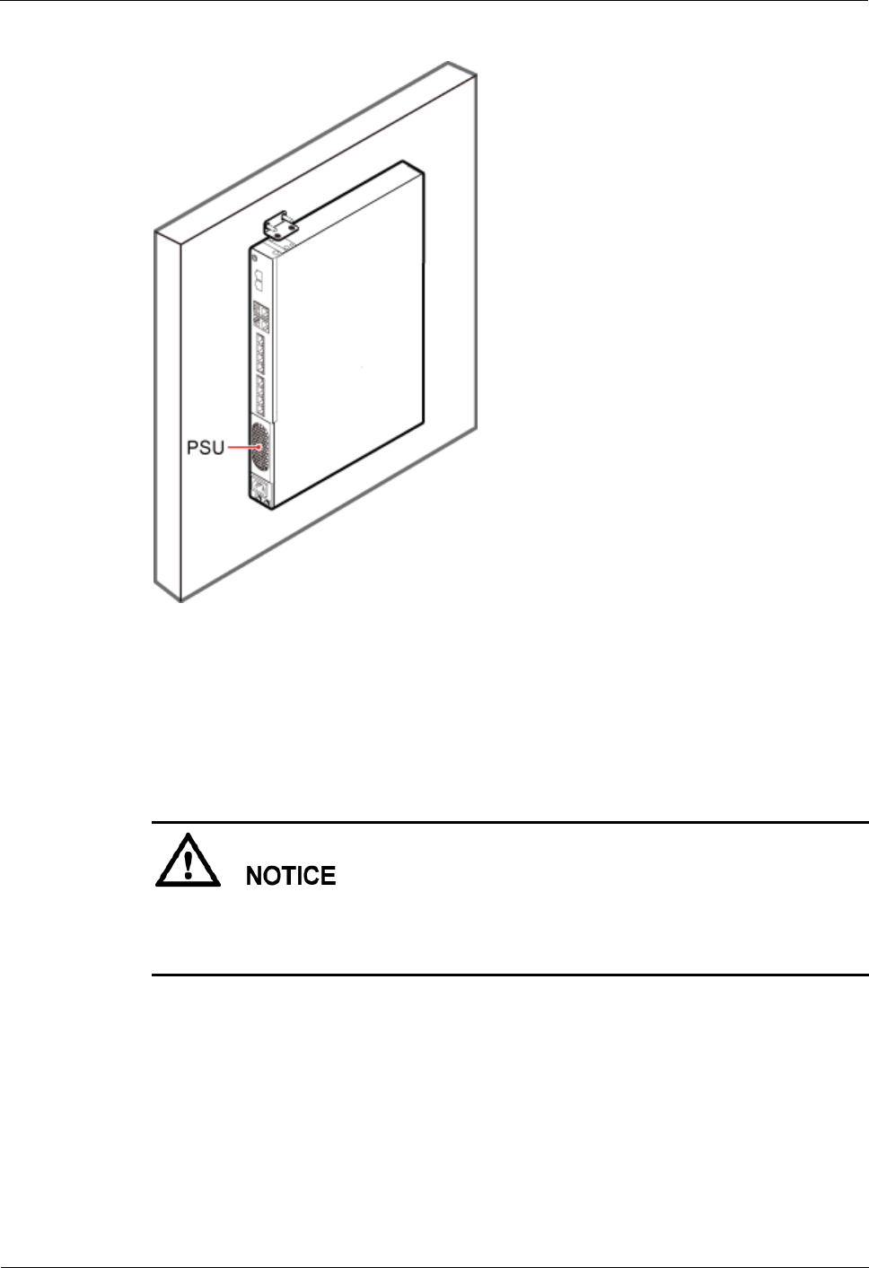
Figure 5-7 shows an RHUB3908 installed on a wall.
LampSite
Installation Guide
5 Installing an RHUB3908
Issue 08 (2014-12-30)
Huawei Proprietary and Confidential
Copyright © Huawei Technologies Co., Ltd.
17
Figure 5-7 RHUB3908 installed on a wall
5.1.2 Installation Clearance Requirements of an RHUB3908
When an RHUB3908 is installed in a 19-inch cabinet, rack, shelf, or on a wall, a minimum
clearance is required for easy cabling and operation and maintenance. A recommended
installation clearance is provided based on experience.
Do not install or place inflammable materials above or under an RHUB3908.
A clearance of 350 mm must be reserved in front of the air intake vent of the fan of the
power supply unit (PSU) for maintenance.
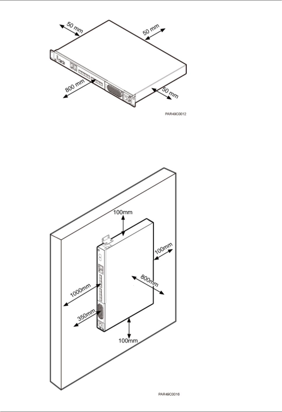
Figure 5-8 shows the installation clearance for the RHUB3908 installed in a 19-inch cabinet,
rack, or shelf.
LampSite
Installation Guide
5 Installing an RHUB3908
Issue 08 (2014-12-30)
Huawei Proprietary and Confidential
Copyright © Huawei Technologies Co., Ltd.
18
Figure 5-8 Installation clearance for an RHUB3908 installed in a 19-inch cabinet, rack, or shelf
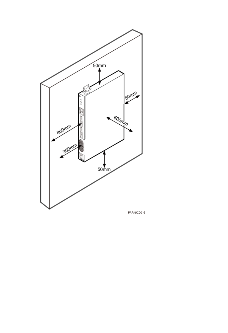
Figure 5-9 and Figure 5-10 shows the recommended and minimum installation clearance
respectively when the RHUB3908 is installed on a wall.
Figure 5-9 Recommended installation clearance for a wall-mounted RHUB3908 (unit: mm)
LampSite
Installation Guide
5 Installing an RHUB3908
Issue 08 (2014-12-30)
Huawei Proprietary and Confidential
Copyright © Huawei Technologies Co., Ltd.
19
Figure 5-10 Minimum installation clearance for a wall-mounted RHUB3908 (unit: mm)
5.1.3 Installation Environment of an RHUB3908
The installation environment of an RHUB3908 involves the running environment
specifications for the RHUB3908 and other specifications.
RHUB3908 Running Environment Specifications
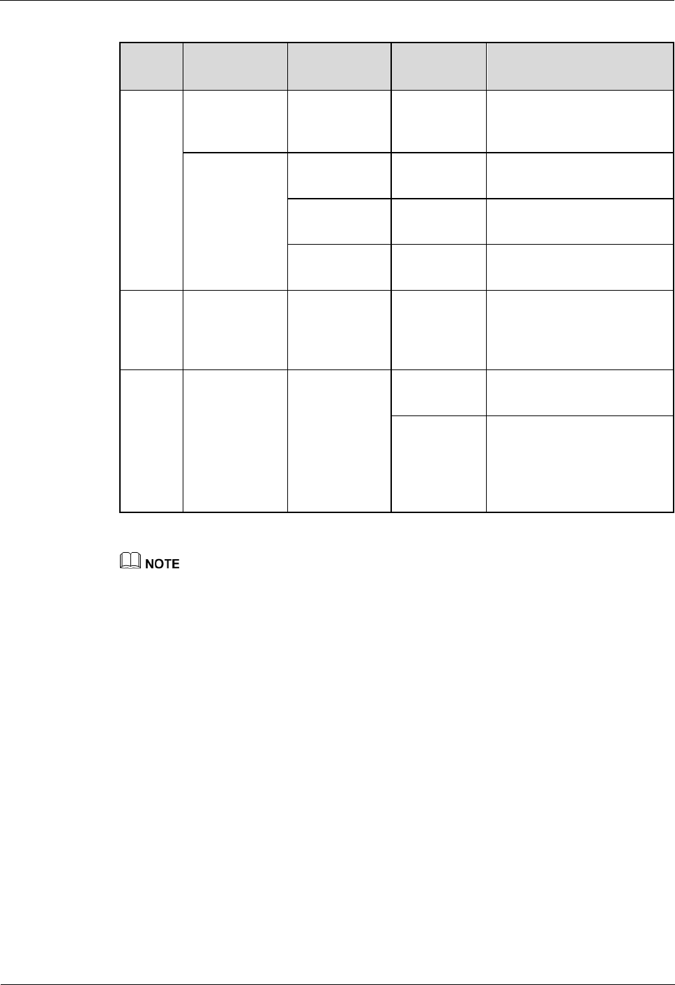
Table 5-1 shows the environment specifications for the RHUB3908 installed indoors.
The temperature and humidity of the installation position must ensure normal operation.
A cool and ventilated place is recommended.
The heat dissipation holes on the RHUB3908 cannot be blocked.
LampSite
Installation Guide
5 Installing an RHUB3908
Issue 08 (2014-12-30)
Huawei Proprietary and Confidential
Copyright © Huawei Technologies Co., Ltd.
20
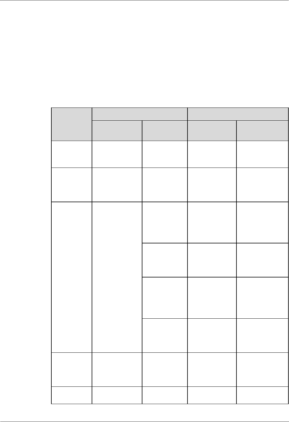
Table 5-1 RHUB3908 environment specifications
Specifi
cations
Installation
Scenario
RHUB3908
Quantity
Condition
Remarks
Operati
ng
tempera
ture
Installed on a
wall or in a
19-inch rack.
N/A
-5°C to
+50°C
N/A
Installed in a
shelf.
1
-5°C to
+45°C
N/A
2
-5°C to
+43°C
N/A
3
-5°C to
+40°C
N/A
Relativ
e
humidit
y
Installed in all
scenarios.
N/A
5% RH to
95% RH
N/A
Altitude
N/A
N/A
-60 m to
+1800 m
Works properly.
1800 m to
4000 m
Above the 1800 m altitude,
the maximum operating
temperature decreases by
1°C each time the altitude
increases by 220 m.
Installing more than one RHUB3908, 1 U space is required between two RHUB3908s.
Other Running Environment Specifications
The RHUB3908 cannot be installed at an air outlet of the heat dissipation box of an air
conditioner or other heat-generating appliances.
The RHUB3908 cannot be installed near a strong heat source.
The RHUB3908 cannot be installed in a position with water dripping, such as outdoor
equipment of air conditioners, pipe, and leaking or dripping roofs.
The installation position must be far from rains. If the RHUB3908 is installed on a wall,
there must be no window on either side of the wall.
The installation position must be far away from high voltage, highly corrosive devices,
flammable or explosive substances, and electromagnetic interference.
The RHUB3908 must be installed in a dry, ventilating, and dust-proof place.
If the RHUB3908 is installed in parking areas or basements, the installation position
must be well-ventilated.
LampSite
Installation Guide
5 Installing an RHUB3908
Issue 08 (2014-12-30)
Huawei Proprietary and Confidential
Copyright © Huawei Technologies Co., Ltd.
21
5.2 Installation Process
The RHUB3908 installation involves installing an RHUB3908 module, installing RHUB3908
cables, checking the RHUB3908 hardware installation, and powering on the RHUB3908.
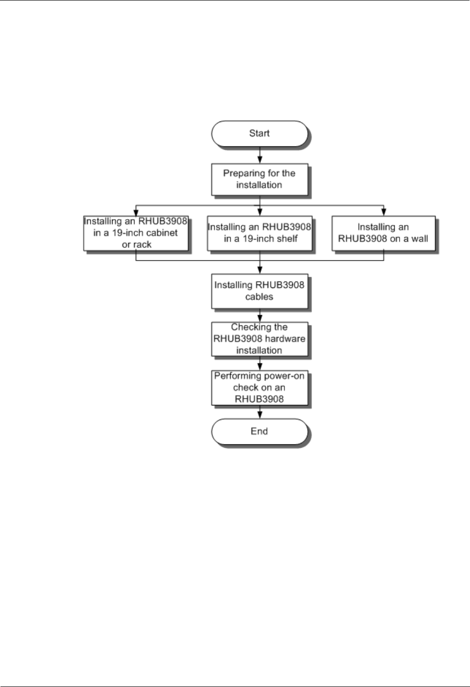
Figure 5-11 shows the RHUB3908 installation process.
Figure 5-11 RHUB3908 installation process
5.3 Installing an RHUB3908
An RHUB3908 can be installed in a cabinet, rack, shelf, or on a wall.
5.3.1 Installing an RHUB3908 in a 19-Inch Cabinet or Rack
This section describes how to install an RHUB3908 in a 19-inch cabinet.
Procedure
The following describes how to install an RHUB3908 with mounting ears in reverse
mode:
LampSite
Installation Guide
5 Installing an RHUB3908
Issue 08 (2014-12-30)
Huawei Proprietary and Confidential
Copyright © Huawei Technologies Co., Ltd.
22
If necessary, request one more person for assistance.
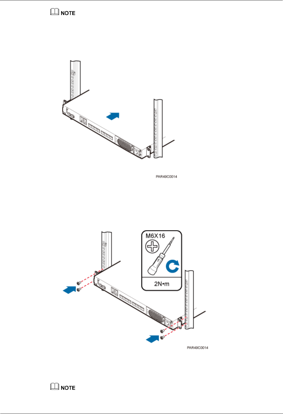
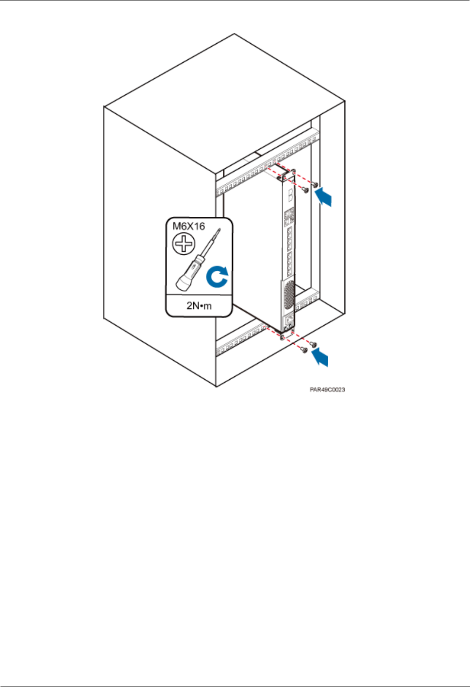
1. With one hand holding it, align the mounting holes with the installation holes, slowly
push the RHUB3908 into the required position in the cabinet, as shown in Figure 5-12.
Figure 5-12 Pushing an RHUB3908 into a cabinet
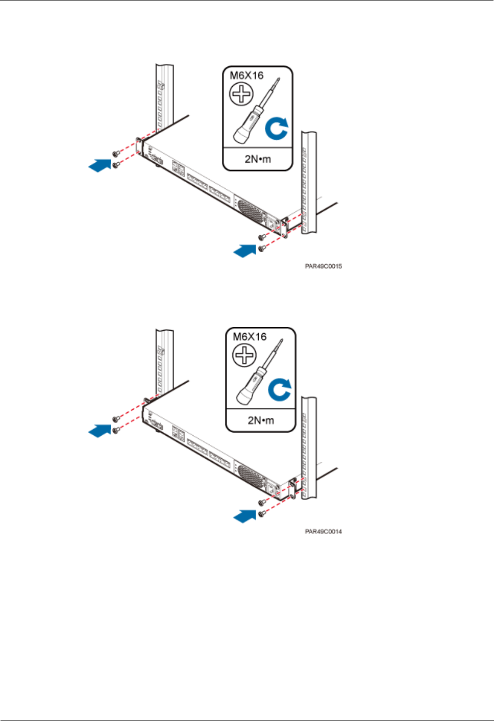
2. Use a torque screwdriver or Phillips screwdriver to tighten the four M6×16 screws with a
torque of 2 N•m, as shown in Figure 5-13.
Figure 5-13 Tightening screws
The following describes how to install an RHUB3908 with mounting ears aligned with
the RHUB3908 panel:
If necessary, request one more person for assistance.

LampSite
Installation Guide
5 Installing an RHUB3908
Issue 08 (2014-12-30)
Huawei Proprietary and Confidential
Copyright © Huawei Technologies Co., Ltd.
23
1. Remove the mounting ears on both sides of the RHUB3908 by removing the four M4×8
screws, as shown in Figure 5-14.
Figure 5-14 Removing mounting ears and screws
2. Use a torque screwdriver or Phillips screwdriver to tighten the four M4×8 screws with a
torque of 1.4 N•m to install the removed mounting ears again, as shown in Figure 5-15.
The mounting ears must be aligned with the RHUB3908 panel.
Figure 5-15 Installing mounting ears in standard mode
3. With one hand holding it, align the mounting holes with the installation holes, slowly
push the RHUB3908 into the required position in the cabinet, as shown in Figure 5-16.

LampSite
Installation Guide
5 Installing an RHUB3908
Issue 08 (2014-12-30)
Huawei Proprietary and Confidential
Copyright © Huawei Technologies Co., Ltd.
24
Figure 5-16 Pushing an RHUB3908 into a cabinet
4. Use a torque screwdriver or Phillips screwdriver to tighten the four M6×16 screws with a
torque of 2 N•m, as shown in Figure 5-17.
Figure 5-17 Tightening screws
----End
5.3.2 Installing an RHUB3908 in a 19-Inch Shelf
If a shelf houses more than one RHUB3908, 1 U space is required between two RHUB3908s.
The PSU must be installed at the bottom of the cabinet.

LampSite
Installation Guide
5 Installing an RHUB3908
Issue 08 (2014-12-30)
Huawei Proprietary and Confidential
Copyright © Huawei Technologies Co., Ltd.
25
Procedure
The following describes how to install an RHUB3908 with mounting ears installed in
reverse mode:
If necessary, request one more person for assistance.
1. With one hand holding it, align the mounting holes with the installation holes, slowly
push the RHUB3908 into the required position in the shelf.
2. Use a torque screwdriver or Phillips screwdriver to tighten the four M6×16 screws with a
torque of 2 N•m, as shown in Figure 5-18.
Figure 5-18 Tightening screws
The following describes how to install an RHUB3908 with mounting ears installed in
standard mode:
If necessary, request one more person for assistance.
1. Remove the mounting ears on both sides of the RHUB by removing the four M4×8
screws, as shown in Figure 5-19.
LampSite
Installation Guide
5 Installing an RHUB3908
Issue 08 (2014-12-30)
Huawei Proprietary and Confidential
Copyright © Huawei Technologies Co., Ltd.
26
Figure 5-19 Removing mounting ears and screws
2. Use a torque screwdriver or Phillips screwdriver to tighten the four M4×8 screws with a
torque of 1.4 N•m to install the removed mounting ears again, as shown in Figure 5-20.
The mounting ears must be aligned with the RHUB panel.
Figure 5-20 Installing mounting ears in standard mode
3. With one hand holding it, align the mounting holes with the installation holes, slowly
push the RHUB3908 into the required position in the cabinet, as shown in .
4. Use a torque screwdriver or Phillips screwdriver to tighten the four M6×16 screws with a
torque of 2 N•m, as shown in Figure 5-21.
LampSite
Installation Guide
5 Installing an RHUB3908
Issue 08 (2014-12-30)
Huawei Proprietary and Confidential
Copyright © Huawei Technologies Co., Ltd.
27
Figure 5-21 Tightening screws
----End
5.3.3 Installing an RHUB3908 on a Wall
An RHUB3908 can be installed on a wall.
Procedure
1. The mounting ears are installed in reverse mode by default. Before installing an
RHUB3908 on a wall, modify the installation mode of the mounting ears on the
RHUB3908.
Use a torque screwdriver or Phillips screwdriver to remove the mounting ears on both
sides of the RHUB3908 by removing the four M4×8 screws, as shown in Figure 5-22.

LampSite
Installation Guide
5 Installing an RHUB3908
Issue 08 (2014-12-30)
Huawei Proprietary and Confidential
Copyright © Huawei Technologies Co., Ltd.
28
Figure 5-22 Removing screws and mounting ears
Rotate the mounting ears 90 degrees clockwise, and use a torque screwdriver or Phillips
screwdriver to secure the mounting ear with a torque of 1.4 N•m, as shown in Figure
5-23.
Figure 5-23 Installing mounting ears and screws
Step 2 Determine the position on the wall for installing the RHUB3908 based on the requirements
in the engineering blueprint and Installation Clearance Requirements of an RHUB. Place the
RHUB3908 to the position to be installed against the wall, and then mark the four anchor
points where the mounting ear screws are fastened using a marker, as shown in Figure 5-24.

LampSite
Installation Guide
5 Installing an RHUB3908
Issue 08 (2014-12-30)
Huawei Proprietary and Confidential
Copyright © Huawei Technologies Co., Ltd.
29
Figure 5-24 Anchor points for installing an RHUB3908 on a wall
(1) Level
(2) RHUB3908
(3) Wall
To prevent inhalation or eye contact with dust, take adequate preventive measures when
drilling holes.
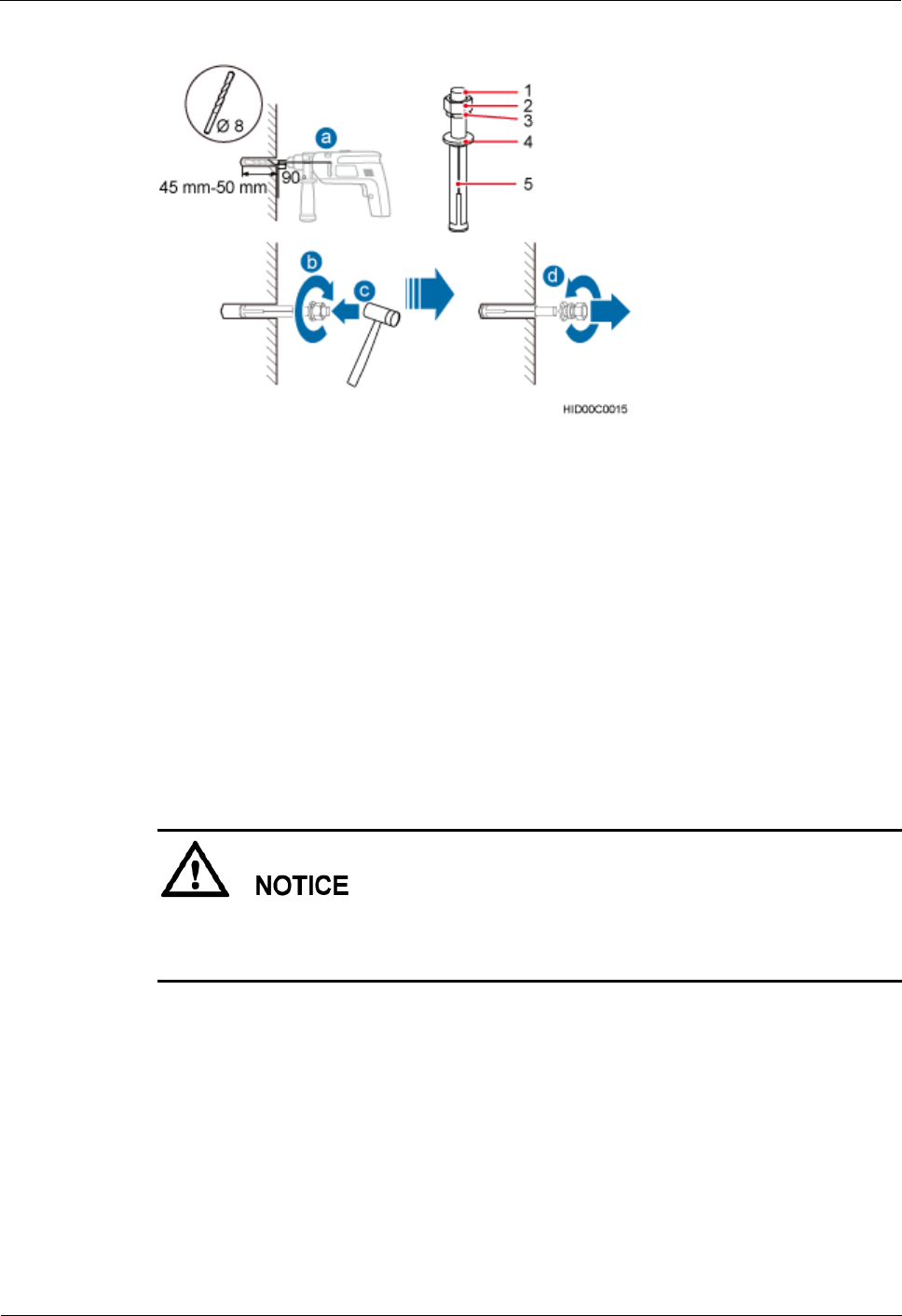
Step 3 Drill holes at the anchor point and install expansion bolts, as shown in Figure 5-25.
LampSite
Installation Guide
5 Installing an RHUB3908
Issue 08 (2014-12-30)
Huawei Proprietary and Confidential
Copyright © Huawei Technologies Co., Ltd.
30
Figure 5-25 Drilling holes and installing expansion bolts
(1) M6×60
expansion bolt
(2) Nut
(3) Spring
washer
(4) Flat washer
(5) Extension
tub
1. Use a hammer drill with bit 8 to drill holes with a diameter of 8 mm and a depth of 45
mm to 50 mm at the marked anchor points. All the holes have the same depth.
2. Use a vacuum cleaner to clear the dust inside and around each hole. If the distance
between two holes is incorrect, mark and drill holes again.
3. Partially tighten an expansion bolt and place it vertically into each hole.
4. Use a rubber mallet to hit the expansion bolt until the entire expansion sleeve is in the
hole.
5. Remove the M6×60 bolt, nut, spring washer, and flat washer from each expansion bolt in
sequence.
After removing an expansion bolt, ensure that the top of the expansion sleeve is level with the
wall. If it is not level, the RHUB3908 cannot be installed on the concrete floor evenly and
securely.
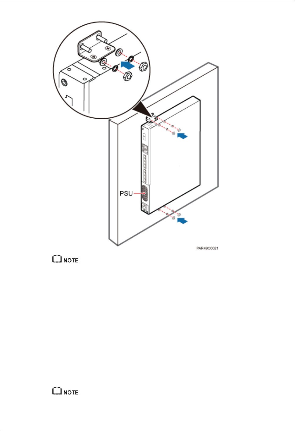
Step 4 Align the mounting holes with the four M6×60 expansion bolts. Install spring washer 6 and
flat washer 6 in sequence on each M6×60 expansion bolt, insert the bolts to each expansion
tub, and then use a torque wrench or socket wrench to tighten the four M6×60 bolts with a
torque of 5 N•m to secure the RHUB3908 to the wall, as shown in Figure 5-26.
LampSite
Installation Guide
5 Installing an RHUB3908
Issue 08 (2014-12-30)
Huawei Proprietary and Confidential
Copyright © Huawei Technologies Co., Ltd.
31
Figure 5-26 Installing an RHUB3908 on a wall
As shown in the preceding figure, when the RHUB3908 is placed against the wall, ensure that the
RHUB3908 panel is vertical to the ground and the PSU is on the lower part of the RHUB3908 panel.
----End
5.4 Installing RHUB3908 Cables
This section describes how to install cables for an RHUB3908.
5.4.1 Requirements for Cable Layout
Cables must be routed according to the specified cabling requirements to prevent signal
interference.
If a cable listed below is not required, skip the requirements for routing the cable.

LampSite
Installation Guide
5 Installing an RHUB3908
Issue 08 (2014-12-30)
Huawei Proprietary and Confidential
Copyright © Huawei Technologies Co., Ltd.
32
General Requirements for Cable Layout
中国标准
综合布线系统工程设计规范 GB 50311-2007
综合布线工程验收规范(含条文说明) GB 50312-2007
安全防范工程技术规范 GB 50348-2004
电子信息系统机房施工及验收规范 GB 50462-2008
智能建筑工程质量验收规范 GB 50339-2003
建筑电气工程施工质量验收规范 GB 50303-2002
通信管道工程施工及验收技术规范 GB 50374-2006
国际标准
用户建筑综合布 ISO/IEC 11801
商业建筑电信布线标准 EIA/TIA 568
商业建筑电信布线安装标准 EIA/TIA 569
商业建筑通信基础结构管理规范 EIA/TIA 606
商业建筑通信接地要求 EIA/TIA 60
信息系统通用布线标准 EN 50173
信息系统布线安装标准 EN 50174
Bending radius
The bending radius of a power cable or a protection ground (PGND) cable is at least
three times the diameter of the cable.
The bending radius of an optical cable is at least 20 times the diameter of the optical
cable, and the minimum bending radius of the branch at each end of the optical cable is
30 mm.
The bending radius of the signal cable must be at least five times the diameter of the
cable.
Cable Binding
Cables of the same type are bound together.
Different types of cables must be separately routed with a minimum spacing of 30 mm
and cannot be entangled or crossed.
The cables are bound tightly and neatly and the cable sheath is intact.
The cable ties face the same direction and all cable ties bound at similar positions must
be in a straight line.
The extra length of each indoor cable tie must be cut off. A slack of 5 mm is reserved for
each outdoor cable tie. All cut surfaces have no sharp edges.
Labels or nameplates are attached to both ends, joints, or turns of cables after they are
installed.
Safety
穿管/线槽采用钢管或阻燃聚氯乙烯硬质管,线槽的截面利用率应为 30%~50%,
穿管的截面利用率应为 25%~30%。

LampSite
Installation Guide
5 Installing an RHUB3908
Issue 08 (2014-12-30)
Huawei Proprietary and Confidential
Copyright © Huawei Technologies Co., Ltd.
33
Cables are placed away from sharp objects or wall burrs. If these positions are inevitable,
protection pipes are required for the cables.
Cables are routed away from heat sources, or heat-insulation materials are added
between cables and heat sources.
Cables are routed away the cooling vents of the RHUB3908.
A clearance is reserved at turns of a cable or the position close to a device, facilitating
cable and device maintenance. The recommended clearance is about 0.1 m.
Requirements for Special Cables
Ethernet Cable
A maximum of 100 Ethernet cables can be bundled if no PVC pipes are used. If pipes are
used, a maximum of 24 Ethernet cables can be led through a pipe. In this case, ensure
that 1/3 space inside the pipes must be vacant.
Power cable
Positions for routing power cables meet requirements of the engineering design.
Cables are routed only by qualified and trained personnel before all preparations are
made.
Cables are routed in an untangled and orderly fashion.
PGND cable
PGND cables are buried in the ground or routed indoors. They cannot be routed
overhead before they are routed into the equipment room.
Outer conductors of coaxial cables and both ends of the shield layers on shielded cables
are in proper electrical contact with the metal surface of the equipment to which they are
connected.
PGND cables and signal cables are installed in an untangled and orderly fashion. A
certain distance is reserved between them to prevent interference from each other.
Fuses or switches are not allowed on PGND cables.
Other devices cannot be used for electrical connections of PGND cables.
All the metal parts in the equipment are reliably connected to the ground terminal.
Optical cable
Cables are routed in an untangled and orderly fashion.
Optical fibers cannot be bound at turns.
Optical fibers cannot be stretched with too much force or stepped on, and they are far
away from sharp objects. Heavy objects cannot be placed on optical cables.
When optical cables are routed, the extra length of the cables is coiled around special
devices, such as a fiber coiler.
Even strength is applied when optical cables are coiled and optical cables cannot be bent
in a forcible manner.
Vacant optical connectors are covered with dust-proof caps.
Fiber optic cables cannot be squeezed by the cabinet door when routed through the
cabinet.
If optical cables need to be routed on the tower platform, the optical cables are routed
along the inner side of the guard rail and the distance between the guard rail and the
cable is the shortest one.
LampSite
Installation Guide
5 Installing an RHUB3908
Issue 08 (2014-12-30)
Huawei Proprietary and Confidential
Copyright © Huawei Technologies Co., Ltd.
34
If optical cables need to be routed close to a device on the tower, the optical cables are
secured to the guard rail or pole with cable clips and the device cannot be far away from
the position for securing the optical cables.
If the optical cable close to a device on the tower is too long, the optical cables are
wrapped and secured to the tower.
5.4.2 RHUB3908 Cable List
This section describes the connector types and connections of the RHUB3908 cables.
Table 5-2 lists RHUB3908 cables.
Table 5-2 RHUB3908 cable list
Cable
One End
The Other End
Connector
Connected
to...
Connector
Connected to...
PGND cable
OT terminal
(M4, 6 mm2
[0.009 in.2])
Ground screws
on the
RHUB3908
OT terminal
(M6, 6 mm2
[0.009 in.2])
Ground terminal
on the external
ground bar
RHUB3908
Power
Supply Cable
C13 female
connector
AC power
input socket on
the
RHUB3908
3-pin connector
External power
input socket
CPRI Optical
Fiber
DLC connector
CPRI port on
the LBBP,
WBBP or
UBBP in the
BBU
DLC connector
CPRI0 or CPRI1
port on the
RHUB3908
CPRI0 or
CPRI1 port on
the
RHUB3908
DLC connector
CPRI0 or CPRI1
port on the
RHUB3908
CPRI port on
the LBBP,
WBBP or
UBBP in the
BBU
FC connector,
SC connector, or
LC connector
ODF
CPRI0 or
CPRI1 port on
the
RHUB3908
FC connector,
SC connector, or
LC connector
ODF
Ethernet
Cable
RJ45 connector
CPRI_E0~CP
RI_E7 port on
the
RHUB3908
RJ45 connector
CPRI_E0~CPRI_
E1 port on the
pRRU3901
(Optional)
RHUB3908
RJ45 connector
EXT_ALM
port on the
Bare end
Alarm signal port
of the monitored

LampSite
Installation Guide
5 Installing an RHUB3908
Issue 08 (2014-12-30)
Huawei Proprietary and Confidential
Copyright © Huawei Technologies Co., Ltd.
35
Cable
One End
The Other End
Connector
Connected
to...
Connector
Connected to...
Alarm Cable
RHUB3908
equipment
If one end of the CPRI cable is connected to the DLC connector, the other end connects the BBU, or
RHUB3908 through the DLC connector. If one end of the CPRI cable is connected to the ODF
adapter, the other end connects the BBU or RHUB3908 through a connector corresponding to the
adapter. The connectors include the FC connector, SC connector, and LC connector.
The Extender can be used to lengthen the distance between the RHUB3908 and the pRRU3901
connected using the Ethernet cable. If the Extender is used, the Ethernet cable is divided into two
parts, one between the RHUB3908 and the Extender and the other between the Extender and the
pRRU3901.
5.4.3 Cable Connections
This section describes the cable connections for an RHUB3908.
Figure 5-27 shows the cable connections for an RHUB3908. The port of GE0, GE1 and ETH
are reserved.
Figure 5-27 Cable connections for an RHUB3908
(1) CPRI optical cable
(2) RHUB3908 alarm cable
(3) Ethernet cable
(4) RHUB3908 power cable
(5) PGND cable
-
The Extender can be used to lengthen the distance between the RHUB3908 and the pRRU3901
connected using the Ethernet cable. If the Extender is used, the Ethernet cable is divided into two parts,
one between the RHUB3908 and the Extender and the other between the Extender and the pRRU3901.
5.4.4 RHUB3908 Cable Installation Process
This section describes the process of installing RHUB3908 cables.
Figure 5-28 shows the RHUB3908 cable installation process.

LampSite
Installation Guide
5 Installing an RHUB3908
Issue 08 (2014-12-30)
Huawei Proprietary and Confidential
Copyright © Huawei Technologies Co., Ltd.
36
Figure 5-28 RHUB3908 cable installation process
5.4.5 Installing an RHUB3908 PGND Cable
An RHUB3908 PGND cable ensures proper grounding of an RHUB3908.
Prerequisites
The OT terminals at both ends of the PGND cable are prepared.
Context
The yellow and green or green PGND cable is a single cable. The cross-sectional area of the
PGND cable is 6 mm2 (0.009 in.2). Both ends of the cable are OT terminals, as shown in
Figure 1.
Figure 5-29 Exterior of a PGND cable
(1) OT terminal (6 mm2 [0.009 in.2], M4)
(2) OT terminal (6 mm2 [0.009 in.2], M6)
LampSite
Installation Guide
5 Installing an RHUB3908
Issue 08 (2014-12-30)
Huawei Proprietary and Confidential
Copyright © Huawei Technologies Co., Ltd.
37
If the PGND cable is provided by the customer, a copper-core cable with a minimum cross-sectional
area of 6 mm2 (0.009 in.2) or 10 AWG is recommended.
The OT terminals at both ends of the PGND cable are assembled at the site.
The M6 OT terminal has the default size. You can replace it with another OT terminal of the
expected size based on the site requirement.
Ensure proper grounding of the RHUB3908 using a PGND cable.
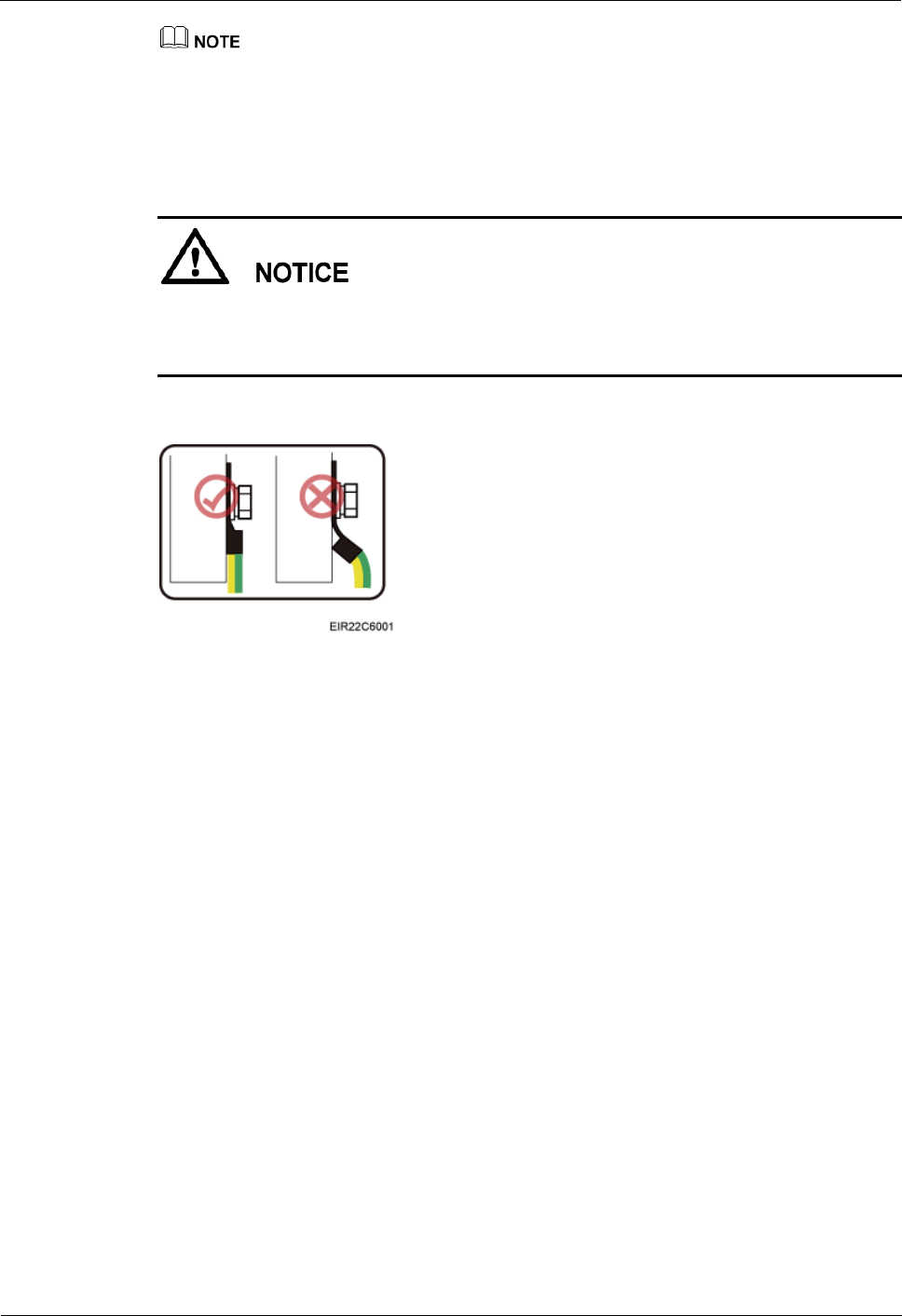
When installing the PGND cable, tightly press the OT terminal in the correct direction, as
shown in Figure 5-30.
Figure 5-30 Correct direction of an OT terminal for the PGND cable
Procedure
1. Route the PGND cable by referring to Requirements for Cable Layout.
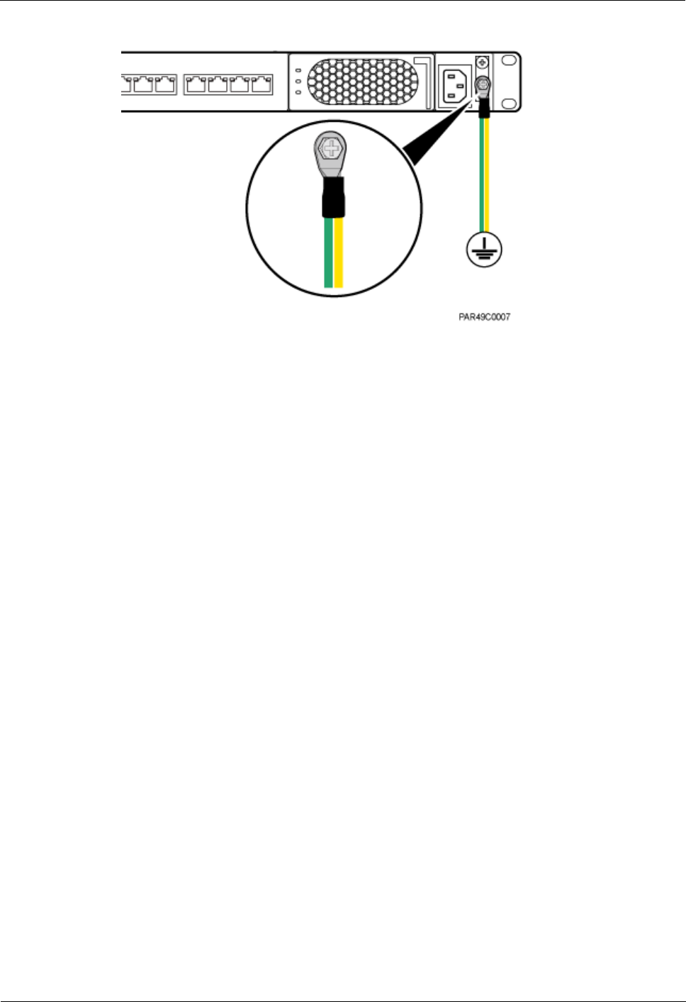
Step 2 Use a torque screwdriver or Phillips screwdriver to secure the M4 OT terminal at one end of
the PGND cable to the ground screw on the RHUB3908 panel with a torque of 1.4 N•m. If the
OT terminal is a one-hole OT terminal, connect it to the ground screw on the lower part of the
RHUB3908 panel, as shown in Figure 5-31.
LampSite
Installation Guide
5 Installing an RHUB3908
Issue 08 (2014-12-30)
Huawei Proprietary and Confidential
Copyright © Huawei Technologies Co., Ltd.
38
Figure 5-31 Installing an RHUB3908 PGND cable
Step 3 Use a torque screwdriver or Phillips screwdriver to secure the M8 OT terminal at one end of
the PGND cable to the wiring terminal on the ground bar at the site with a torque of 1.4 N•m.
----End
Follow-up Procedure
1. Route the cable, and then use a cable tie to bind the cable. For details, see Requirements
for Cable Layout.
2. Label the installed cable. For details, see section 8.3 Attaching an L-Shaped Label.
5.4.6 Installing an Ethernet Cable
This section describes how to install an Ethernet cable. A pRRU3901 can have two
transmission ports or three transmission ports, requiring the same installation operations. This
section uses the pRRU3901 with three transmission ports as an example.
Prerequisites
Ethernet cables are not delivered, and they must be prepared onsite. You need to use a
network cable tester to test the Ethernet cable connection.
The Ethernet cable must be of Category 5e (enhanced) or higher. In addition, its
cross-sectional area must be 24 AWG or larger and frame spread rating must be CM or
higher. With the internal PoE module providing power, the maximum length of an
Ethernet cable is 100 m. With the Extender, the distance of the pRRU3901 and
RHUB3908 can be extended by the Extender up to a total distance of 200 m.
Context
The Ethernet cable has the following functions:
Provides power supply for the pRRU when connected to the CPRI_E0 port on the
pRRU.
Transmits CPRI signals between an RHUB3908 and a pRRU.

LampSite
Installation Guide
5 Installing an RHUB3908
Issue 08 (2014-12-30)
Huawei Proprietary and Confidential
Copyright © Huawei Technologies Co., Ltd.
39
Using the CPRI_E1 port on the pRRU3901 has the same Ethernet cable connection to the
RHUB3908 as using the CPRI_E0 port. The following section describes the connection using
the CPRI_E0 port.
Procedure
1. Make the Ethernet cables.
1. Assemble an RJ45 connector and an Ethernet cable by following instructions in
Assembling the Unshielded RJ45 Connector and the Ethernet Cable of Installation
Reference.
Follow pin assignment instructions described in section Ethernet Cable in LampSite Hardware
Description to assemble the unshielded RJ45 connector and the Ethernet cable. Otherwise, the
transmission signal quality deteriorates and CPRI links may be disconnected.
2. Check whether the made RJ45 connector is qualified by following instructions in
Checking the Appearance of Metal Contact Strips.
3. To complete the assembly of the other end, repeat Step 1.1 and Step 1.2.
4. Check whether the touch points on the connectors at both ends are normally conducted
and well contacted and whether the connections are correct by following instructions in
Testing the Connection of Assembled Cables of Installation Reference.
Step 2 Remove the dustproof cap of the CPRI_E0 port on the pRRU3901.
Step 3 Connect the RJ45 connector at one end of the Ethernet cable to the CPRI_E0 port on the
pRRU3901 panel.
Step 4 Optional: Connect the RJ45 connector at the other end of the Ethernet cable to the output
port of the Extender. Then, connect the RJ45 connector at one end of another Ethernet cable
to the input port of the Extender.
If the Extender is used, the Ethernet cable is divided into two parts, one between the
RHUB3908 and the Extender and the other between the Extender and the pRRU3901.
Step 5 Connect the RJ45 connector at the other end of the Ethernet cable to any port ranging from
CPRI_E0 to CPRI_E7 on the RHUB3908 panel based on the engineering design, as shown in
Figure 5-32.
Figure 5-32 Install an Ethernet cable between an RHUB3908 and a pRRU3901
(1) Ethernet cable
(2) CPRI_E0 port on the pRRU3901
LampSite
Installation Guide
5 Installing an RHUB3908
Issue 08 (2014-12-30)
Huawei Proprietary and Confidential
Copyright © Huawei Technologies Co., Ltd.
40
The pRRU3901 can have two transmission ports plus PWR port or three transmission ports (plus PWR
port or no PWR port). The Ethernet cable connection between the pRRU3901 in any appearance and the
RHUB3908 is similar. This section uses the pRRU3901 with three transmission ports plus no PWR port
as an example.
----End
Follow-up Procedure
1. Route the cable, and then use a cable tie to bind the cable. For details, see 5.4.1
Requirements for Cable Layout.
2. Label the installed cable. For details, see section 8.3 Attaching an L-Shaped Label.
5.4.7 Installing CRPI Optical Cables
Optical fibers can be used to interconnect BBU and RHUB3908s, or cascade RHUB3908s.
Context
Multi-mode optical modules for CPRI ports are labeled MM and each has a black or gray
puller.
Single-mode optical modules are labeled SM and each has a blue puller.
For details about the connection of CPRI optical cables, see Typical Networking in
LampSite Technical Description and CPRI Optical Fiber in LampSite Hardware
Description.
An optical module to be installed must match the rate of its corresponding port.
The performance of an optical module that is exposed to the air for more than 20 minutes may
be abnormal. Therefore, you must insert a fiber optic cable into an unpacked optical module
within 20 minutes.
Procedure
1. Install an optical module, as shown in Figure 5-33 and Figure 5-34.
1. Remove the dust-proof cap from the CPRI port on the RHUB3908 panel.
2. Remove the dust-proof cap on the optical module.
3. Lower the puller of the optical module.
4. Insert the optical module into the CPRI port on the RHUB3908, BBU or ODF.
5. Raise the puller of the optical module.

LampSite
Installation Guide
5 Installing an RHUB3908
Issue 08 (2014-12-30)
Huawei Proprietary and Confidential
Copyright © Huawei Technologies Co., Ltd.
41
Figure 5-33 Removing the dust-proof cap from a port
Figure 5-34 Installing an optical module
Step 2 Install a CPRI optical cable, as shown in Figure 5-35.
1. Remove the dust-proof cap from the optical cable connector.
2. Install the optical cables by referring to Table 5-3.
Table 5-3 CPRI optical cable connections
One End
The Other End
Connect
or
Connected to
Connector
Connected to
DLC
connecto
r
BBU3900/LBBP&WBBP&
UBBP/CPRI port
DLC connector
CPRI0 or CPRI1 port on
the RHUB3908
CPRI0 or CPRI1 port on the
RHUB3908
CPRI0 or CPRI1 port on
the RHUB3908
BBU3900/LBBP&WBBP&
UBBP/CPRI port
FC, SC, or LC
connector
ODF
CPRI0 or CPRI1 port on the
RHUB3908
LampSite
Installation Guide
5 Installing an RHUB3908
Issue 08 (2014-12-30)
Huawei Proprietary and Confidential
Copyright © Huawei Technologies Co., Ltd.
42
If one end of the CPRI cable is connected to the DLC connector, the other end connects the BBU or
RHUB3908 through the DLC connector. If one end of the CPRI cable is connected to the ODF
adapter, the other end connects the BBU or RHUB3908 through a connector corresponding to the
adapter. The connectors include the FC connector, SC connector, and LC connector.
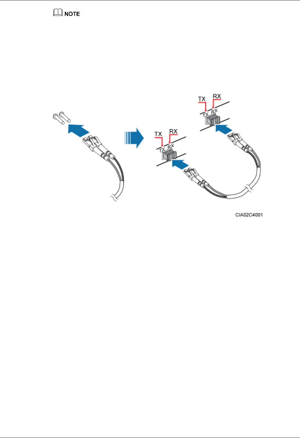
When connecting the CPRI cable to the TX and RX ports of the optical module through connectors
in a cross manner, ensure that one end of a core of the CPRI cable is connected to the TX port and
the other end is connected to the RX port. Figure 5-35 shows how to install a CPRI optical cable for
connecting the BBU and RHUB3908s.
Figure 5-35 Installing an CRPI optical cable
----End
Follow-up Procedure
1. Route the cable, and then use a cable tie to bind the cable. For details, see 5.4.1
Requirements for Cable Layout.
2. Label the installed cable. For details, see section 8.3 Attaching an L-Shaped Label.
5.4.8 Installing an RHUB3908 Alarm Cable (Optional)
An RHUB3908 alarm cable transmits dry node alarm signals.
Prerequisites
Connectors for an alarm cable are prepared.
Context
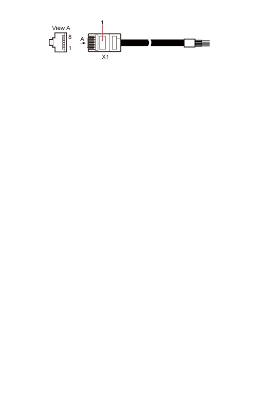
Figure 5-36 shows the exterior of an RHUB3908 alarm cable. RHUB Cable List shows the
installation position on both ends of the RHUB3908 cable.
LampSite
Installation Guide
5 Installing an RHUB3908
Issue 08 (2014-12-30)
Huawei Proprietary and Confidential
Copyright © Huawei Technologies Co., Ltd.
43
Figure 5-36 RHUB3908 alarm cable
Procedure
1. Connect the RJ45 connector on one end of the alarm cable to the EXT_ALM port on the
RHUB3908.
Step 2 Connect the other end of the alarm cable to the alarm cable port on the device to be
monitored.
----End
Follow-up Procedure
1. Route the cable, and then use a cable tie to bind the cable. For details, see 5.4.1
Requirements for Cable Layout.
2. Label the installed cable. For details, see section 8.3 Attaching an L-Shaped Label.
5.4.9 Installing an RHUB3908 Power Cable
The RHUB3908 power cable provides 110 V AC/220 V AC power supply for the RHUB3908.
Procedure
1. Route the power cable by referring to Requirements for Cable Layout.
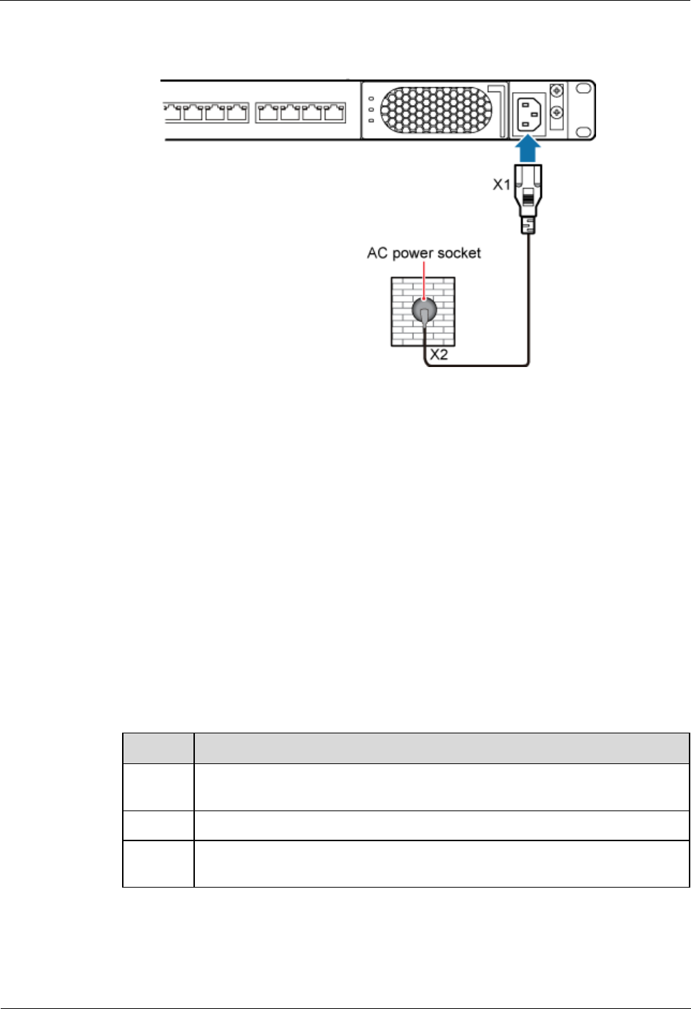
Step 2 Connect the power connector on the X1 end to the AC power input port on the RHUB3908
panel, as shown in Figure 5-37.
Step 3 Connect the power connector on the X2 end to the external power supply port, as shown in
Figure 5-37.
LampSite
Installation Guide
5 Installing an RHUB3908
Issue 08 (2014-12-30)
Huawei Proprietary and Confidential
Copyright © Huawei Technologies Co., Ltd.
44
Figure 5-37 Installing an RHUB3908 power cable
----End
Follow-up Procedure
1. Route the cable, and then use a cable tie to bind the cable. For details, see 5.4.1
Requirements for Cable Layout.
2. Label the installed cable. For details, see section 8.3 Attaching an L-Shaped Label.
5.5 Checking the RHUB3908 Hardware Installation
After an RHUB3908 is installed, check the installation of hardware including the devices and
related cables.
Table 5-4 lists the hardware installation checking items.
Table 5-4 Hardware installation checking list
No.
Item
1
The position for each device conforms to the engineering design and meets the
space requirement.
2
Ensure that the RHUB3908 is properly installed.
3
The surface of the RHUB3908 is neat and clean. The external paint is intact.
The labels, tags, and nameplates are correct, legible, and complete.
Table 5-5 lists the checking list of the power cable and PGND cable connections.

LampSite
Installation Guide
5 Installing an RHUB3908
Issue 08 (2014-12-30)
Huawei Proprietary and Confidential
Copyright © Huawei Technologies Co., Ltd.
45
Table 5-5 Checklist for power cable and PGND cable connections
No.
Item
1
The power cables and PGND cables comply with the requirements of local
regulations.
2
The power cables or the PGND cables are not inversely connected or
short-circuited.
3
The power cables and PGND cables are bound separately from other cables.
4
Labels are attached to both ends of the power cables, PGND cables, optical
fibers, and Ethernet cables.
5
The power cables and PGND cables are intact.
6
The power cables and PGND cables have no weld nugget.
7
No breaking device such as a switch or fuse lies in the electric connection of
the grounding system.
8
The redundant part of PGND cable is stripped off.
9
The lugs at both ends of the power cable or PGND cable are securely soldered
or crimped.
10
The flat washers and spring washers are fixed securely and closely at all the
wiring terminals.
11
The work GND cable and PGND cable of the BTS share a group of grounding
conductors with the lightning and GND cables of the building.
Table 5-6 lists the check items of the signal cable connection.
Table 5-6 Checklist for the signal cable connection
No.
Item
1
The connectors of the signal cables must securely connected.
2
The connectors of the signal cables are intact.
3
The signal cables are intact.
4
The cable ties are evenly spaced. The signal cables are bound neatly with cable
ties to proper tightness, and arranged at even intervals in the same direction.
5
The extra length of the cable ties is cut and removed. The cut surfaces of the
indoor cables are smooth and have no sharp edges.
6
The cable layout facilitates maintenance and expansion.
7
Correct and clear labels are attached to both ends of the signal cables.
8
The distance between the bundled fiber tails and the RHUB3908 panel is less
than 70 mm.
LampSite
Installation Guide
5 Installing an RHUB3908
Issue 08 (2014-12-30)
Huawei Proprietary and Confidential
Copyright © Huawei Technologies Co., Ltd.
46
Table 5-7 lists the checking items for other cable connections.
Table 5-7 Checklist for other cable connections
No.
Item
1
The connectors of the other cables must securely connected.
2
Labels on the cables are legible and bound based on the engineering
requirements. The cables must be bound tightly and neatly. The sheaths of the
cables must not be damaged.
3
Positions for routing the cables must meet requirements of the engineering
design.
5.6 Power-on Check on an RHUB3908
This section describes the power-on check on the RHUB3908 after the RHUB3908 hardware
is installed and checked.
Context
Power-on check involves high-voltage operation. Be cautious when conducting the power-on
check. Any direct contact with the input voltage or indirect contact through damp objects
might endanger your life.
Procedure
1. Measure the RHUB3908 earth resistance.
If...
Then...
The RHUB3908 earth resistance is less
than 10 ohms
Go to Step 2.
The RHUB3908 earth resistance is
equal to or larger than 10 ohms
Find out the cause and ensure that the resistance
meets requirement. Then, go to Step 2.
Step 2 Measure the voltage of the RHUB3908.
If...
Then...
The external power supply ranges from
100 V AC to 240 V AC
Go to Step 3.

LampSite
Installation Guide
5 Installing an RHUB3908
Issue 08 (2014-12-30)
Huawei Proprietary and Confidential
Copyright © Huawei Technologies Co., Ltd.
47
If...
Then...
The external power supply does not
range from 100 V AC to 240 V AC
Find out the cause and ensure that the resistance
meets requirement. Then, go to Step 3.
Step 3 Power on the RHUB3908. Wait 3 to 5 minutes, check the status of the RUN indicator of the
RHUB3908 after the RHUB3908 runs properly.
If the Status of
the RUN
Indicator...
It Indicates that...
Then...
Steady on
The power supply is
normal while the board
is faulty.
Power off the RHUB3908, and power on it
again after rectifying the board fault.
Steady off
There is no power input
or the board is faulty.
Power off the RHUB3908, and check the
power input again. Rectify the board faulty
and power on the RHUB3908 again if the
power input is normal.
On for 1s and off
for 1s
The devices work
properly.
End the operation.
On for 0.125s
and off for
0.125s
The board software is
being uploaded.
Power off the RHUB3908 if the uploading
is not finished in 5 minutes, and check
whether the configuration file is correct.
Power on the RHUB3908 again after the
fault is rectified.
----End

LampSite
Installation Guide
6 Installing a pRRU3901
Issue 08 (2014-12-30)
Huawei Proprietary and Confidential
Copyright © Huawei Technologies Co., Ltd.
48
6 Installing a pRRU3901
About This Chapter
This chapter describes the pRRU3901 installation process. The pRRU3901 can have two
transmission ports (plus PWR port) or three transmission ports (plus PWR port or no PWR
port). Unless otherwise specified, this document uses the pRRU3901 with three
transmission ports plus no PWR port as an example.
The pRRU3901 with three transmission ports plus no PWR port is named the pRRU3901
AWS+PCS+WIFI in North Americain.
6.1 Information About the Installation
This section describes the information that you must be familiar with before installing a
pRRU3901, including the pRRU3901 product family, installation scenarios, installation space
and environment requirements.
6.2 Obtaining the MAC Address (Optional)
Before installing a pRRU3901, record the media access control (MAC) address, which will be
used during pRRU3901 commissioning. This section applies only when a pRRU3901 with
three transmission ports is configured with a Wi-Fi daughter board.
6.3 Installation Process
This section describes the pRRU3901 installation process, which involves installing a
pRRU3901, and cables, checking the pRRU3901 hardware installation, and powering on the
pRRU3901.
6.4 Installing a pRRU3901
This section describes the pRRU3901 installation process. A pRRU3901 can be installed on a
wall, ceiling, indoor metal pole, or keel.
6.5 Installing pRRU3901 Cables
This section describes the procedure of installing the pRRU3901 cables.
6.6 Checking the pRRU3901 Hardware Installation
pRRU3901 hardware installation checking includes hardware and cable installation checking.
6.7 Powering on the pRRU3901

LampSite
Installation Guide
6 Installing a pRRU3901
Issue 08 (2014-12-30)
Huawei Proprietary and Confidential
Copyright © Huawei Technologies Co., Ltd.
49
This section describes the power-on check on the pRRU3901 after the pRRU3901 hardware is
installed and checked.
6.1 Information About the Installation
This section describes the information that you must be familiar with before installing a
pRRU3901, including the pRRU3901 product family, installation scenarios, installation space
and environment requirements.
6.1.1 pRRU3901 Product Family
This chapter describes the configurations and functions of the pRRU3901 components.
Table 6-1 lists the pRRU3901 product family.
Table 6-1 pRRU3901 product family
Categor
y
Equipment
Optional
Item
Quantity
Function
Main
equipmen
t
pRRU3901
Mandatory
1
Processes the radio frequency
signals.
External
antenna
Optional
2
Provides external antennas
for the pRRU3901.
NOTE
Configure two external antennas
for each RF daughter board.
Auxiliary
device
Mounting kits
Mandatory
1
Supports the pRRU3901
installation on a wall, pole,
ceiling, or keel. The
mounting kits vary with the
pRRU3901 installation mode.
Extender
Optional
1
Extends the distance between
the pRRU3901 and
RHUB3908.
6.1.2 pRRU3901 Installation Scenario
The pRRU3901 can be installed on a wall, ceiling, pole, or keel. The following table describes
the installation in different scenarios.
LampSite
Installation Guide
6 Installing a pRRU3901
Issue 08 (2014-12-30)
Huawei Proprietary and Confidential
Copyright © Huawei Technologies Co., Ltd.
50
Installing a pRRU3901 on a wall
The pRRU3901 must keep a minimum of 0.5 m away from the power equipment with interference,
and keep a minimum of 2 m away from the source with radiation.
The pRRU3901 must keep away from a metal wall to avoid the impact on the antenna performance.
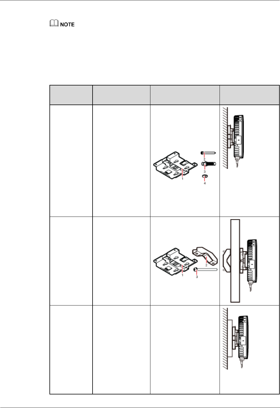
When a pRRU3901 is installed on a wall, installation modes vary with the quality of wall, as
shown in Table 6-2.
Table 6-2 Wall-mounted suggestion
Installation
Mode
Requirements
Mounting Brackets
Installation
Diagram
Installing the
pRRU3901 on
a wall by
drilling holes
For details, see
pRRU
Installed on a
Wall.
The wall can
bear a load at
least four times
the weight of a
pRRU3901.
The screws must
be tightened with
a torque of 10
N·m. This
ensures the
screws work
properly and the
wall remains
intact without
cracks in it.
1. Plate
2. Screw (M6X50)
3. Plastic expansion
sleeve
4. Flat washer
Installing the
pRRU3901 on
a wall using a
V clamp
through an
attachment
plate
For details, see
pRRU
Installed on a
Plate.
The wall can
bear a load at
least four times
the weight of a
pRRU3901.
The thickness of
the wall is less
than the bolt
length (80 mm).
1. Plate
2. V clamp
3. Bolt (M6X80)
Installing the
pRRU3901 on
a wall using a
plate on a
metal wall
The wall cannot
bear a load at
least four times
the weight of the
pRRU3901. For
example, EPS
walls, MDF
walls, or walls
cannot be drilled.
The wall is too
thick to drill, and
the pRRU3901
The plate is prepared by
customers.
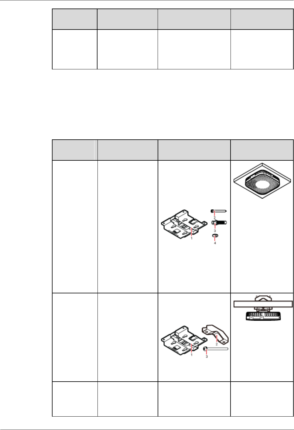
LampSite
Installation Guide
6 Installing a pRRU3901
Issue 08 (2014-12-30)
Huawei Proprietary and Confidential
Copyright © Huawei Technologies Co., Ltd.
51
Installation
Mode
Requirements
Mounting Brackets
Installation
Diagram
cannot be
installed on a
wall using a V
clamp through an
attachment plate.
Installing a pRRU3901 on a ceiling
When a pRRU3901 is installed on a ceiling, installation modes vary with the quality of the
ceiling, as shown in Table 6-3.
Table 6-3 Ceiling-mounted suggestion
Installation
Mode
Requirements
Mounting Brackets
Installation
Diagram
Installing the
pRRU3901 on
a ceiling by
drilling holes
For details, see
pRRU
Installed on a
Ceiling.
The ceiling, such
as a concrete
ceiling, can bear
a load at least
four times the
weight of the
pRRU3901.
The screws must
be tightened with
a torque of 10
N·m. This
ensures the
screws work
properly and the
ceiling remains
intact without
cracks in it.
1. Plate
2. Screw (M6X50)
3. Plastic expansion
sleeve
4. Flat washer
Installing the
pRRU3901 on
a ceiling using
a V clamp
through an
attachment
plate
For details, see
pRRU
Installed on a
Plate.
The ceiling, such
as a concrete
ceiling, can bear
a load at least
four times the
weight of the
pRRU3901.
The thickness of
the ceiling is less
than the bolt
length (80 mm).
1. Plate
2. V clamp
3. Bolt (M6X80)
Installing the
pRRU3901 on
a pole
For details, see
A pole under the
ceiling can bear a
load at least four
times the weight of
For details, see Table
6-4.
For details, see Table
6-4.
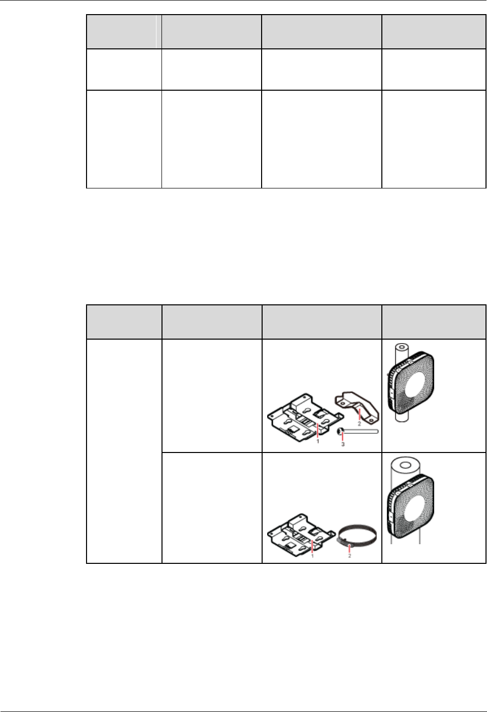
LampSite
Installation Guide
6 Installing a pRRU3901
Issue 08 (2014-12-30)
Huawei Proprietary and Confidential
Copyright © Huawei Technologies Co., Ltd.
52
Installation
Mode
Requirements
Mounting Brackets
Installation
Diagram
pRRU
Installed on a
Pole.
the pRRU3901.
Installing the
pRRU3901 on
a keel
For details, see
pRRU
Installed on a
Keel.
A keel under the
ceiling can bear a
load at least four
times the weight of
the pRRU3901.
For details, see Table
6-5.
For details, see Table
6-5.
Installing the pRRU3901 on a pole
When a pRRU3901 is installed on a pole, installation modes vary with the diameter of the
pole, as shown in Table 6-4.
Table 6-4 Pole-mounted suggestion
Installation
Mode
Requirements
Mounting Brackets
Installation
Diagram
Installing the
pRRU3901 on
a pole
For details, see
pRRU
Installed on a
Pole.
The diameter of the
pole ranges from 30
mm to 70 mm.
1. Plate
2. V clamp
3. Bolt (M6X80)
The diameter of the
pole ranges from 70
mm to 110 mm.
1. Plate
2. Hose clamp, which is
prepared by the
customer
Installing the pRRU3901 on a keel
The pRRU3901 can be installed on a keel of U-shape, T-shape, or H-shape. For the keels of
other shapes, they are determined based on the onsite requirements.

LampSite
Installation Guide
6 Installing a pRRU3901
Issue 08 (2014-12-30)
Huawei Proprietary and Confidential
Copyright © Huawei Technologies Co., Ltd.
53
Table 6-5 Keel-mounted installation suggestion
Installation
Mode
Requirements
Mounting Brackets
Installation
Diagram
Installing the
pRRU3901 on
a keel
For details, see
pRRU
Installed on a
Keel.
The keel is in
U-shape, T-shape,
H-shape, or other
shapes.
1. Plate
2. V clamp
3. Bolt (M6X80)
shows the
pRRU3901 installed
on a U-shaped keel.
6.1.3 Space Requirements
When the pRRU3901 is installed on a wall, ceiling, pole or keel, the minimum space is
required for easy cabling and O&M. Based on the engineering practice, the recommendation
for the installation space is provided.
During installation, a minimum clearance of 2 m must be reserved between the pRRU3901 working on
the 2.6 GHz band and the Wi-Fi module if they need to process services concurrently.
Figure 6-1 shows the recommended space requirements of the pRRU3901 when the external
antenna is required.
Figure 6-1 Recommended space requirements of the pRRU3901
When the external antenna is required, the recommended space for installing a single
pRRU3901 is described as follows:
At least 300 mm above the pRRU3901 is reserved for maintenance.
At least 300 mm under the pRRU3901 is reserved for cabling.
At least 300 mm on the left of the pRRU3901 is reserved for maintenance.
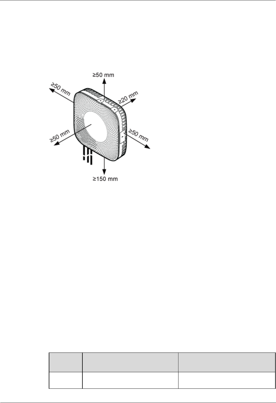
LampSite
Installation Guide
6 Installing a pRRU3901
Issue 08 (2014-12-30)
Huawei Proprietary and Confidential
Copyright © Huawei Technologies Co., Ltd.
54
At least 300 mm on the right of the pRRU3901 is reserved for maintenance.
At least 400 mm in front of the pRRU3901 is reserved for maintenance
At least 20 mm on the back of the pRRU3901 is reserved for ventilation.
Figure 6-2 shows the minimum space requirements of the pRRU3901 when the external
antenna is not required.
Figure 6-2 Minimum space requirements of the pRRU3901
When the external antenna is not required, the minimum space for installing a single
pRRU3901 is described as follows:
At least 50 mm above the pRRU3901 is reserved for maintenance.
At least 150 mm under the pRRU3901 is reserved for cabling.
At least 50 mm on the left of the pRRU3901 is reserved for maintenance.
At least 50 mm on the right of the pRRU3901 is reserved for maintenance.
At least 50 mm in front of the pRRU3901 for maintenance.
At least 20 mm on the back of the pRRU3901 is reserved for ventilation.
6.1.4 pRRU3901 Installation Environment Requirements
The installation environment of a pRRU3901 involves the running environment specifications
for the pRRU3901 and other specifications.
pRRU3901 Running Environment Specifications
Table 6-6 shows the environment specifications for the pRRU3901 installed indoors.
Table 6-6 pRRU3901 environment specifications
Specificat
ions
Condition
Remarks
Operating
temperatur
- 5°C to + 40°C
-

LampSite
Installation Guide
6 Installing a pRRU3901
Issue 08 (2014-12-30)
Huawei Proprietary and Confidential
Copyright © Huawei Technologies Co., Ltd.
55
Specificat
ions
Condition
Remarks
e
Relative
humidity
5% RH to 95% RH
-
Altitude
- 60 m to + 1800 m
Works properly.
1800 m to 4000 m
Above the 1800 m altitude, the
maximum operating temperature
decreases by 1°C each time the
altitude increases by 220 m.
Other Running Environment Specifications
The pRRU3901 cannot be installed at an air outlet of the heat dissipation box of an air
conditioner or other heat-generating appliances.
The pRRU3901 cannot be installed near a strong heat source.
The pRRU3901 cannot be installed in a position with water dripping, such as outdoor
equipment of air conditioners, pipe, and leaking or dripping roofs.
The installation position must be far from rains. If the pRRU3901 is installed on a wall,
there must be no window on either side of the wall.
The installation position must be far away from high voltage, highly corrosive devices,
flammable or explosive substances, and electromagnetic interference.
The pRRU3901 must be installed in a dry, ventilating, and dust-proof place.
If the pRRU3901 is installed in parking areas or basements, the installation position must
be well-ventilated.
6.2 Obtaining the MAC Address (Optional)
Before installing a pRRU3901, record the media access control (MAC) address, which will be
used during pRRU3901 commissioning. This section applies only when a pRRU3901 with
three transmission ports is configured with a Wi-Fi daughter board.
Context
The MAC address indicates the IP address through which a device can be reached.
Procedure
1. Remove the backup WIFI MAC label from the front housing of the pRRU3901 and keep
them secure, as shown in Figure 6-3.

LampSite
Installation Guide
6 Installing a pRRU3901
Issue 08 (2014-12-30)
Huawei Proprietary and Confidential
Copyright © Huawei Technologies Co., Ltd.
56
Do not remove the WIFI MAC label on the side of the pRRU3901 housing.
Before removing the backup WIFI MAC label, photograph it.
Figure 6-3 Removing backup WIFI MAC label
Step 2 Save the MAC according to MAC Collection Template, and report it to the pRRU3901
commissioning personnel.
----End
6.3 Installation Process
This section describes the pRRU3901 installation process, which involves installing a
pRRU3901, and cables, checking the pRRU3901 hardware installation, and powering on the
pRRU3901.
Figure 6-4 shows the pRRU3901 installation process.
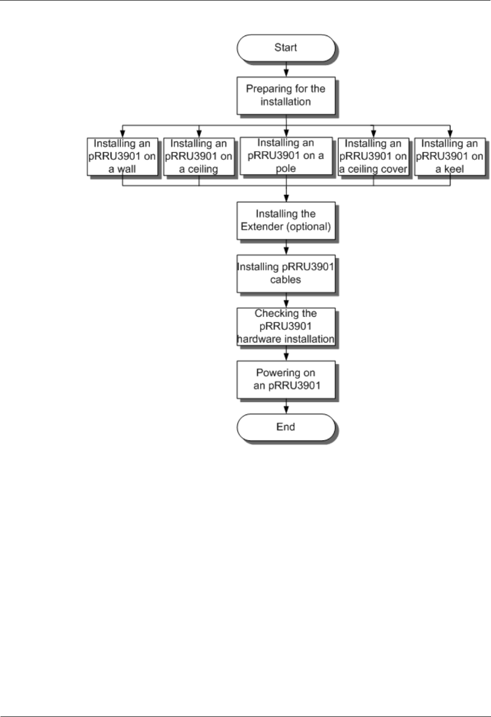
LampSite
Installation Guide
6 Installing a pRRU3901
Issue 08 (2014-12-30)
Huawei Proprietary and Confidential
Copyright © Huawei Technologies Co., Ltd.
57
Figure 6-4 pRRU3901 installation process
6.4 Installing a pRRU3901
This section describes the pRRU3901 installation process. A pRRU3901 can be installed on a
wall, ceiling, indoor metal pole, or keel.

LampSite
Installation Guide
6 Installing a pRRU3901
Issue 08 (2014-12-30)
Huawei Proprietary and Confidential
Copyright © Huawei Technologies Co., Ltd.
58
The pRRU3901 cannot be grounded. If the pRRU3901 is grounded but the RHUB3908 connected to
this pRRU3901 is not, the pRRU3901 may fail to be powered on.
A minimum distance of 50 cm must be reserved between the pRRU3901 and the incandescent lamp.
The installation spacing between the pRRU3901 and the temperature sensor must be greater than 50
cm.
It is good practice to install the pRRU3901 on materials that can tolerate a temperature higher than
65°C and have an ignition point higher than 70°C.
6.4.1 pRRU3901 Installation Kits
This section describes the pRRU3901 installation kits.
Figure 6-5 shows the exterior of the pRRU3901 installation kits.
Figure 6-5 pRRU3901 installation kits
(1) V clamp
(2) Plate
(3) Screw (M6x50)
(4) Plastic expansion sleeve
(5) Bolt (M6x80)
(6) Flat washer
The following figure shows the specifications of the installation plate.
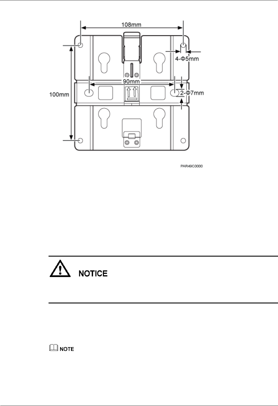
LampSite
Installation Guide
6 Installing a pRRU3901
Issue 08 (2014-12-30)
Huawei Proprietary and Confidential
Copyright © Huawei Technologies Co., Ltd.
59
Figure 6-6 Plate specifications
6.4.2 pRRU3901 Installed on a Wall
If the wall indoors has sufficient load bearing capacity and space, the pRRU3901 is
recommended to install on a wall. If the wall cannot bear the capacity, choose an installation
mode based on site requirements.
Context
This section only describes the procedure of installing the pRRU3901 on a wall without any
other auxiliary devices. The installation procedure of other wall-mounted modes is similar to
that of installing the pRRU3901 on a wall without auxiliary devices.
Procedure
1. Determine the position for installing the pRRU3901 based on the construction blueprint
and the space requirements.
For pRRU3901 installation space requirements, see Space Requirements.
Step 2 Place the plate in the installation position against the wall. Then, level the plate and mark the
two anchor points using a marker, as shown in Figure 6-7.

LampSite
Installation Guide
6 Installing a pRRU3901
Issue 08 (2014-12-30)
Huawei Proprietary and Confidential
Copyright © Huawei Technologies Co., Ltd.
60
Figure 6-7 Anchor points of the pRRU3901 installation kits (unit: mm)
(1) Wall
(2) Plate
(3) Anchor point
To prevent inhalation or eye contact with dust, take adequate preventive measures when
drilling holes.
Step 3 Use a hammer drill with a φ 8 bit to drill holes at the marked anchor points as shown in as
shown in Figure 6-8. Use the cleaner to clean the dust inside and around the holes and
measure the distance between them. If they are inaccurately positioned, re-measure and
re-drill the holes. Then, use a rubber mallet to push the two plastic expansion sleeve into the
holes.
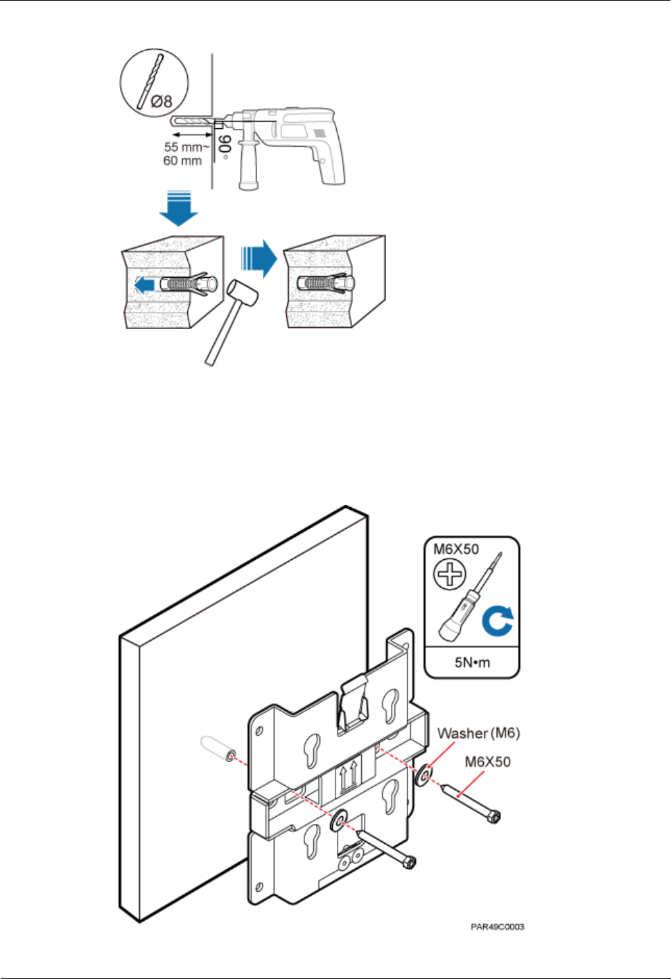
LampSite
Installation Guide
6 Installing a pRRU3901
Issue 08 (2014-12-30)
Huawei Proprietary and Confidential
Copyright © Huawei Technologies Co., Ltd.
61
Figure 6-8 Drilling holes and installing expansion bolts
Step 4 Lead the M6x50 screw through the washer, and then through the drilling holes of the plate to
the plastic expansion sleeve, and tighten the screw to a torque of 5 N•m, as shown in Figure
6-9.
Figure 6-9 Installing the plate
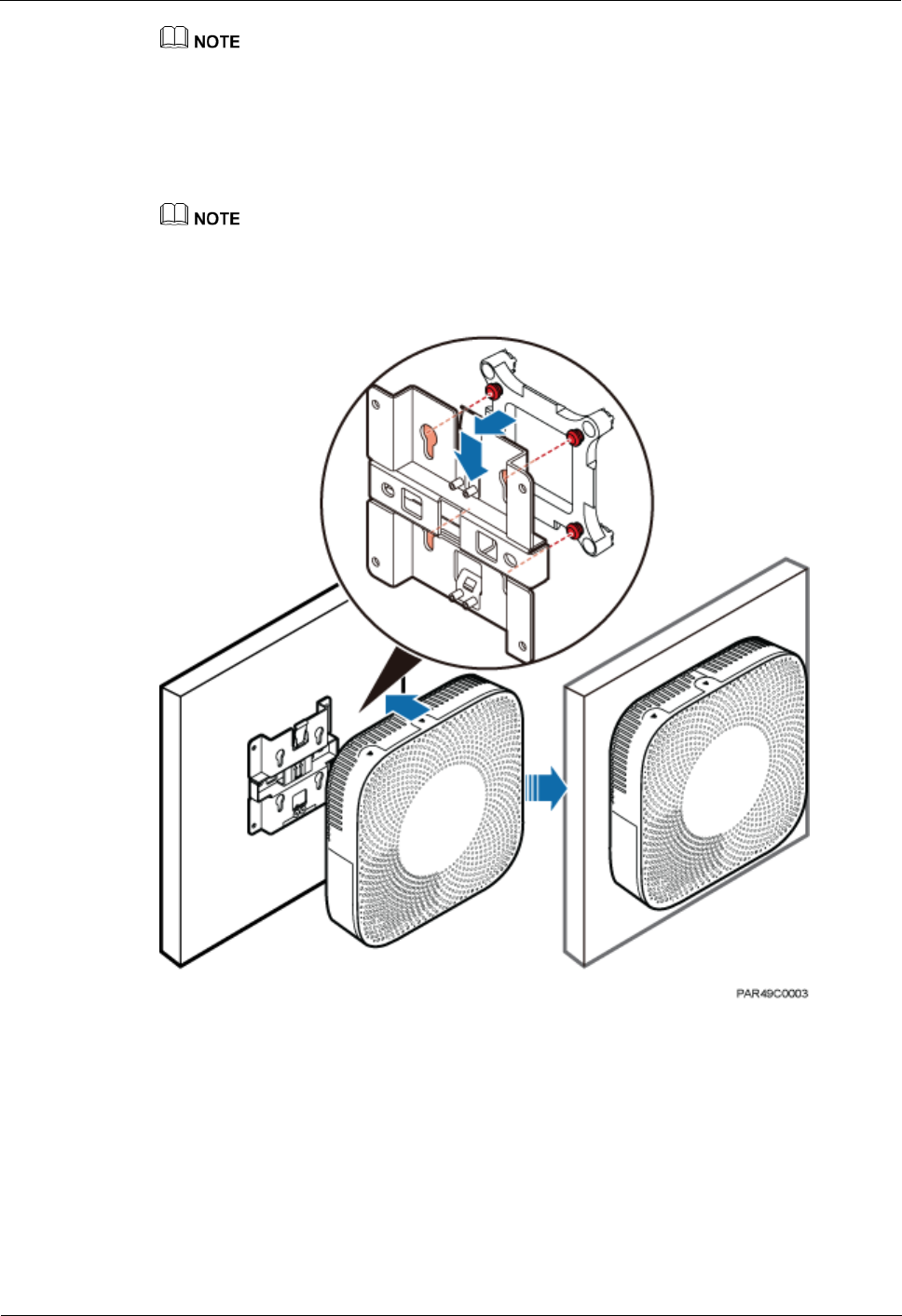
LampSite
Installation Guide
6 Installing a pRRU3901
Issue 08 (2014-12-30)
Huawei Proprietary and Confidential
Copyright © Huawei Technologies Co., Ltd.
62
If the screws cannot be tightened using a Phillips screwdriver, use a hex key or an electric screwdriver to
assist the installation.
Step 5 Fit the four hooks of the pRRU3901 into the installation kits, as shown in Figure 6-10. If the
hooks are properly installed, a slight clack can be heard.
It is recommended that you observe the installation from one side of the pRRU3901 when inserting
hooks into the kits.
Figure 6-10 Installing the pRRU3901 on a plate
----End
6.4.3 pRRU3901 Installed on a Ceiling
This section describes the procedure of installing a pRRU3901 on the ceiling, such as the
concrete ceiling, when the ceiling has sufficient load bearing capacity and installation space.
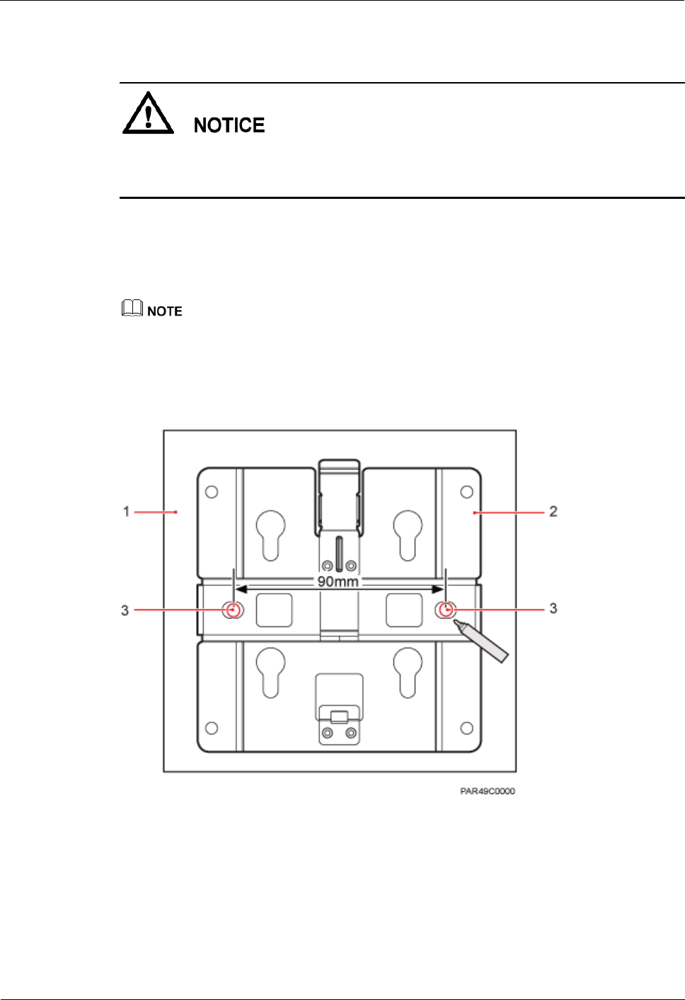
LampSite
Installation Guide
6 Installing a pRRU3901
Issue 08 (2014-12-30)
Huawei Proprietary and Confidential
Copyright © Huawei Technologies Co., Ltd.
63
Context
If the pRRU3901 is installed on the ceiling, the temperature of the ceiling may increase by a
maximum of 30 degrees. Therefore, whether a pRRU3901 can be installed on a ceiling
depends on the ceiling material.
Procedure
1. Determine the position for installing the pRRU3901 based on the construction blueprint
and the space requirements.
For pRRU3901 installation space requirements, see Space Requirements.
Step 2 Place the plate in the installation position against the ceiling. Then, level the plate and mark
the two anchor points using a marker, as shown in Figure 6-11.
Figure 6-11 Anchor points of the pRRU3901 installation kits (unit: mm)
(1) Ceiling
(2) Plate
(3) Anchor point of the bolt

LampSite
Installation Guide
6 Installing a pRRU3901
Issue 08 (2014-12-30)
Huawei Proprietary and Confidential
Copyright © Huawei Technologies Co., Ltd.
64
To prevent inhalation or eye contact with dust, take adequate preventive measures when
drilling holes.
Step 3 Use a hammer drill with a φ 8 bit to drill holes at the marked anchor points as shown in as
shown in Figure 6-12. Use the cleaner to clean the dust inside and around the holes and
measure the distance between them. If they are inaccurately positioned, re-measure and
re-drill the holes. Then, use a rubber mallet to push the two plastic expansion sleeve into the
holes.
Figure 6-12 Drilling holes and installing expansion bolts
Step 4 Lead the M6x50 screw through the washer, and then through the drilling holes of the plate to
the plastic expansion sleeve, and use a torque screwdriver to tighten the screw with a torque
of 5 N•m, as shown in Figure 6-13.
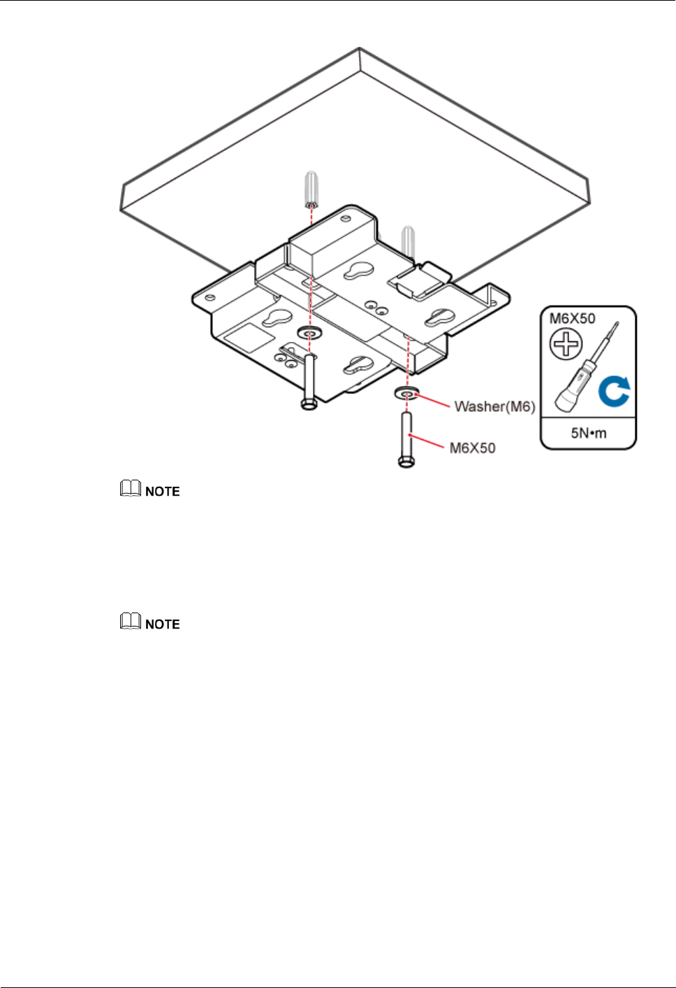
LampSite
Installation Guide
6 Installing a pRRU3901
Issue 08 (2014-12-30)
Huawei Proprietary and Confidential
Copyright © Huawei Technologies Co., Ltd.
65
Figure 6-13 Installing the plate
If the screws cannot be tightened using a Phillips screwdriver, use a hex key or an electric screwdriver to
assist the installation.
Step 5 Fit the four hooks of the pRRU3901 into the installation kits, as shown in Figure 6-14. If the
hooks are properly installed, a slight clack can be heard.
It is recommended that you observe the installation from one side of the pRRU3901 when inserting
hooks into the kits.
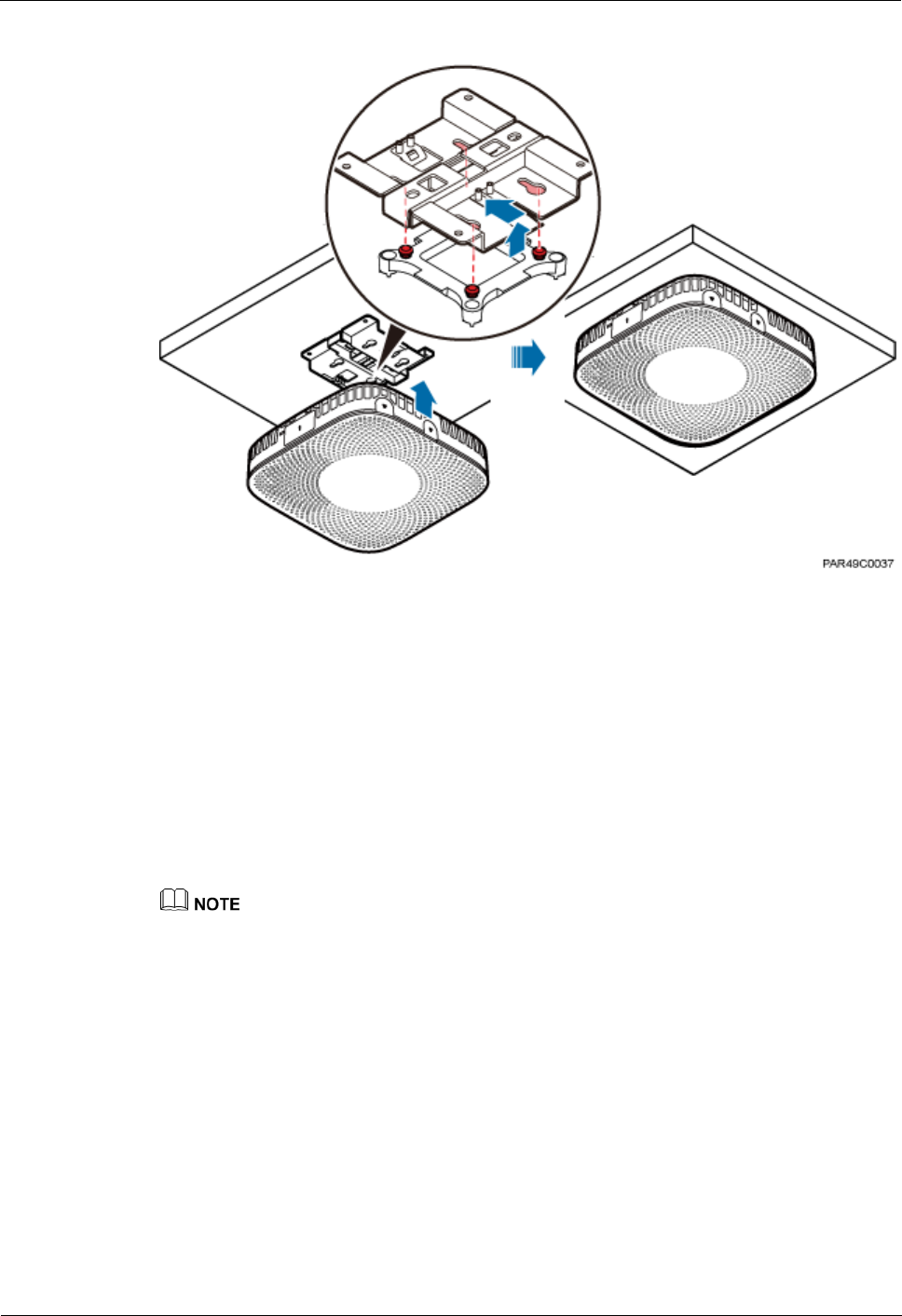
LampSite
Installation Guide
6 Installing a pRRU3901
Issue 08 (2014-12-30)
Huawei Proprietary and Confidential
Copyright © Huawei Technologies Co., Ltd.
66
Figure 6-14 Installing a pRRU3901
----End
6.4.4 pRRU3901 Installed on a Pole
A pRRU3901 can be installed on a metal pole indoors.
Procedure
1. Determine the position for installing the pRRU3901 based on the construction blueprint
and the space requirements.
For pRRU3901 installation space requirements, see Space Requirements.
Step 2 If the diameter of the pole ranges from 30 mm to 70 mm, use the delivered V clamp,
installation plate, and bolts to install the pRRU3901 on the pole. Lead the M6x80 bolt through
the plate, and tighten the bolt to a torque of 5 N•m, as shown in Figure 6-15.

LampSite
Installation Guide
6 Installing a pRRU3901
Issue 08 (2014-12-30)
Huawei Proprietary and Confidential
Copyright © Huawei Technologies Co., Ltd.
67
Figure 6-15 Securing the pRRU3901 installation kits on the metal pole
If the diameter of the pole is larger than 70 mm, use the hose clamp to install the plate on the
pole. The hose clamp is prepared by customers. Tighten the bolt with a torque of 5 N•m, as
shown in Figure 6-16.
Figure 6-16 Securing the pRRU3901 installation kits on the metal pole

LampSite
Installation Guide
6 Installing a pRRU3901
Issue 08 (2014-12-30)
Huawei Proprietary and Confidential
Copyright © Huawei Technologies Co., Ltd.
68
Step 3 Fit the four hooks of the pRRU3901 into the installation kits, as shown in Figure 6-17. If the
hooks are properly installed, a slight clack can be heard.
It is recommended that you observe the installation from one side of the pRRU3901 when inserting
hooks into the kits.
Figure 6-17 Installing a pRRU3901
----End
6.4.5 pRRU3901 Installed on a Plate
If the plate on the ceiling has sufficient load bearing capacity and space installation, the
pRRU3901 can be installed on the plate of the ceiling indoors.
Procedure
1. Determine the position for installing the pRRU3901 based on the construction blueprint
and the space requirements.
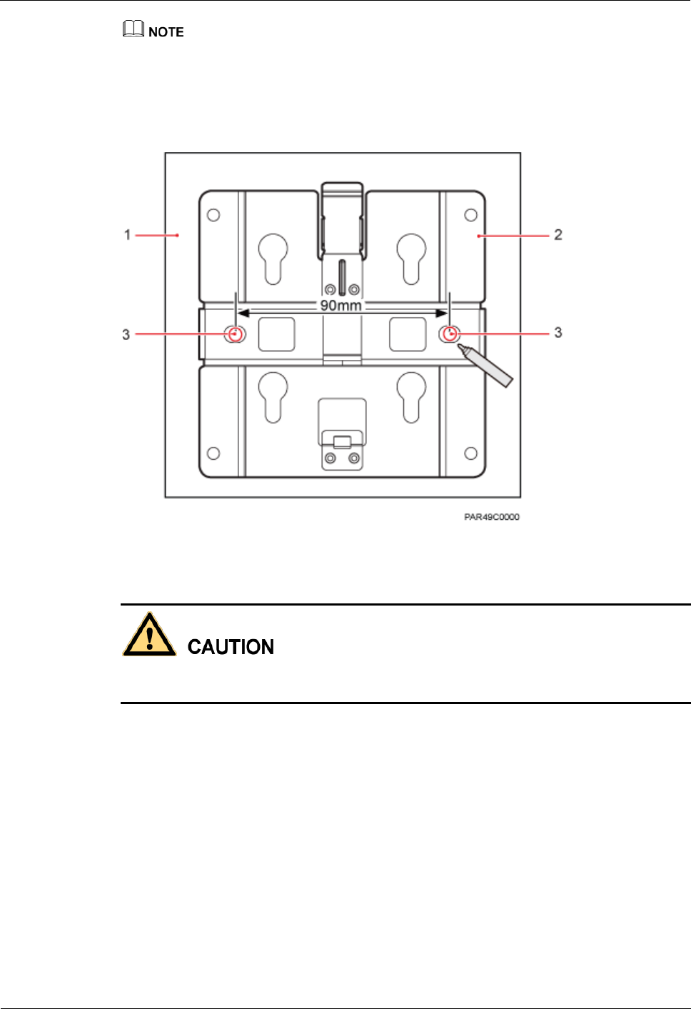
LampSite
Installation Guide
6 Installing a pRRU3901
Issue 08 (2014-12-30)
Huawei Proprietary and Confidential
Copyright © Huawei Technologies Co., Ltd.
69
For pRRU3901 installation space requirements, see Space Requirements.
Step 2 Place the plate in the installation position against the wall. Then, level the plate and mark the
two anchor points using a marker, as shown in Figure 6-18.
Figure 6-18 Anchor points of the pRRU3901 installation kits (unit: mm)
(1) Panel
(2) Plate
(3) Anchor point
To prevent inhalation or eye contact with dust, take adequate preventive measures when
drilling holes.
Step 3 Use a hammer drill with bit 8 to drill holes at the anchor points.
Step 4 Lead the bolt M6x80 through the panel and daughter board, and tighten the torque
screwdriver to a torque of 5 N•m, as shown in Figure 6-19.

LampSite
Installation Guide
6 Installing a pRRU3901
Issue 08 (2014-12-30)
Huawei Proprietary and Confidential
Copyright © Huawei Technologies Co., Ltd.
70
Figure 6-19 Installing the pRRU3901 installation kits
Step 5 Fit the four hooks of the pRRU3901 into the installation kits, as shown in Figure 6-20. If the
hooks are properly installed, a slight clack can be heard.
It is recommended that you observe the installation from one side of the pRRU3901 when inserting
hooks into the kits.
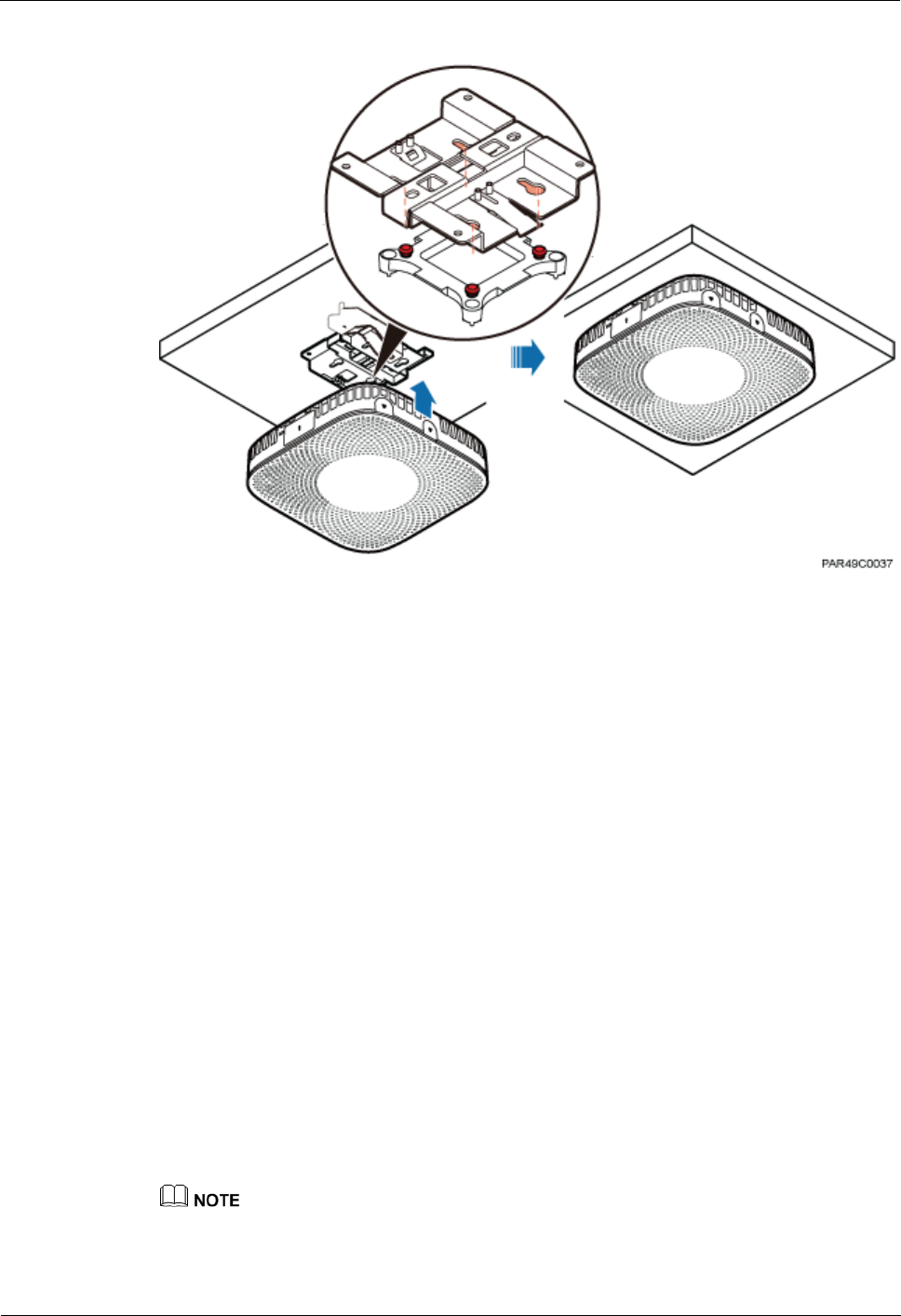
LampSite
Installation Guide
6 Installing a pRRU3901
Issue 08 (2014-12-30)
Huawei Proprietary and Confidential
Copyright © Huawei Technologies Co., Ltd.
71
Figure 6-20 Installing a pRRU3901
----End
6.4.6 pRRU3901 Installed on a Keel
If the ceiling cover cannot bear the pRRU3901, the pRRU3901 can be installed on the keel of
a ceiling.
Context
Before installing the pRRU3901 on a keel, ensure that the keel is strong enough to bear the
pRRU3901.
The installation kits of the pRRU3901 can be installed on the keel of the following
specifications: GBT 11981-2008, JIS A6517-2002, and ASTM C635 C635M-2007. The
installation mode must depends on onsite requirements because there are various keels.
This section describes the procedure of installing a pRRU3901 on the keel of JIS
standard used in Japan. The procedure of installing a pRRU3901 on other keels is the
same as that of installing a pRRU3901 on the keel of JIS standard.
Procedure
1. Determine the position for installing the pRRU3901 based on the construction blueprint
and the space requirements.
For pRRU3901 installation space requirements, see Space Requirements.
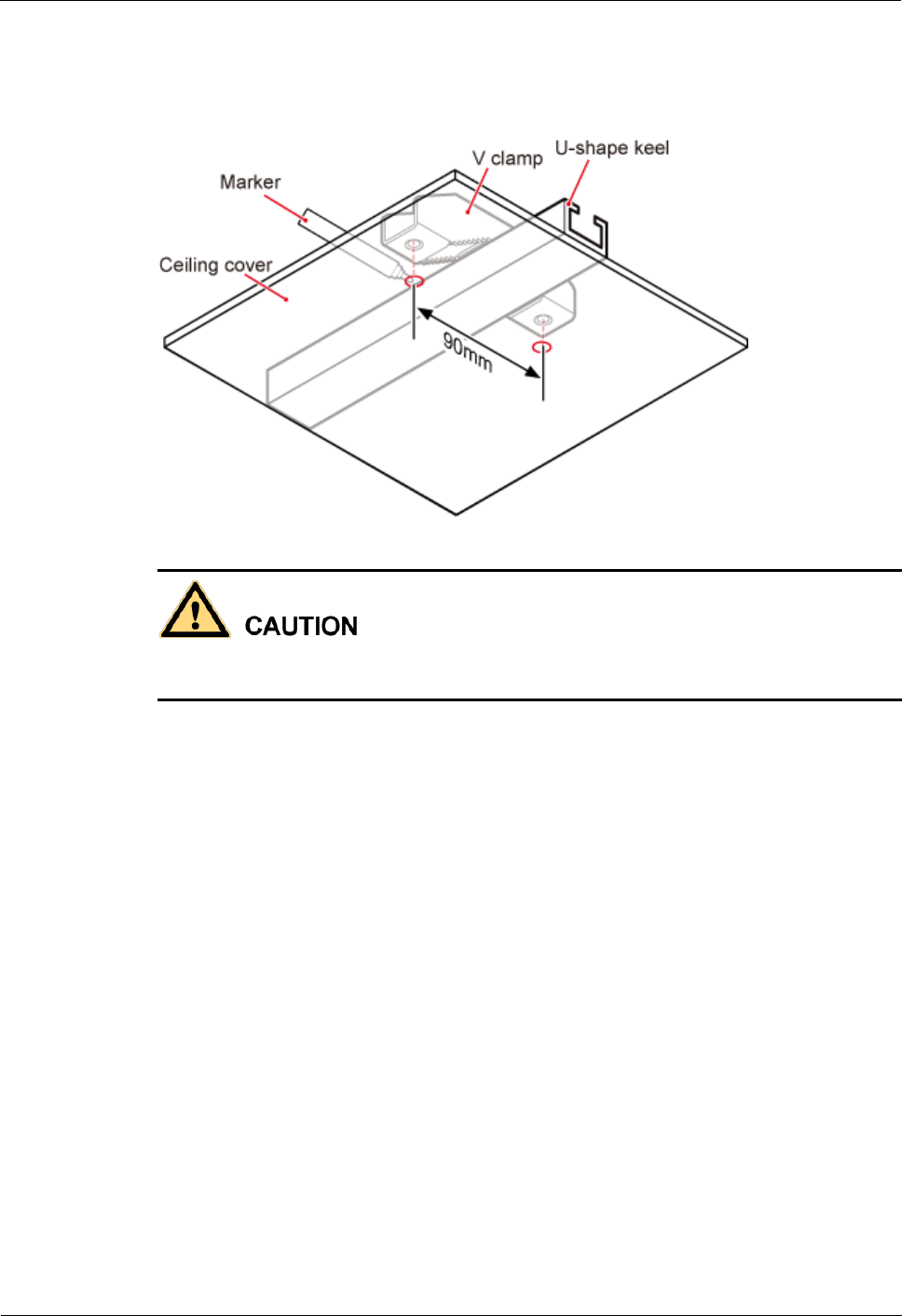
LampSite
Installation Guide
6 Installing a pRRU3901
Issue 08 (2014-12-30)
Huawei Proprietary and Confidential
Copyright © Huawei Technologies Co., Ltd.
72
Step 2 Lead the V clamp on across the keel, and mark the projective position on the cover with a
marker, as shown in Figure 6-21.
Figure 6-21 Anchor points on a plate (unit: mm)
To prevent inhalation or eye contact with dust, take adequate preventive measures when
drilling holes.
Step 3 Use a hammer drill to drill holes at the anchor points. You are advised to use the hammer drill
Ф12.
Step 4 Lead the bolt M6x80 through the installation plate and ceiling cover, and then socket to
tighten the bolt to a torque of 5 N•m, as shown in Figure 6-22.

LampSite
Installation Guide
6 Installing a pRRU3901
Issue 08 (2014-12-30)
Huawei Proprietary and Confidential
Copyright © Huawei Technologies Co., Ltd.
73
Figure 6-22 Installing the pRRU3901 installation kits
Step 5 Fit the four hooks of the pRRU3901 into the installation kits, as shown in Figure 6-23. If the
hooks are properly installed, a slight clack can be heard.
It is recommended that you observe the installation from one side of the pRRU3901 when inserting
hooks into the kits.
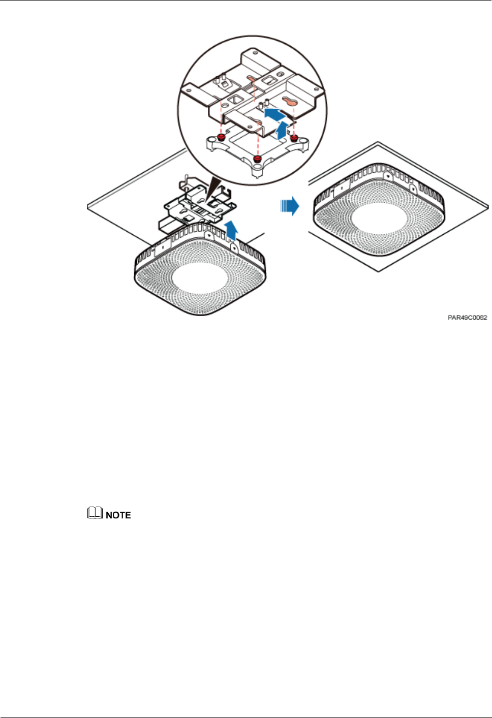
LampSite
Installation Guide
6 Installing a pRRU3901
Issue 08 (2014-12-30)
Huawei Proprietary and Confidential
Copyright © Huawei Technologies Co., Ltd.
74
Figure 6-23 Installing a pRRU3901
----End
6.5 Installing pRRU3901 Cables
This section describes the procedure of installing the pRRU3901 cables.
6.5.1 Requirements for Cable Layout
Cables must be routed according to the specified cabling requirements to prevent signal
interference.
If certain cables listed below are not required, skip the requirements for routing these cables.
General Requirements for Cable Layout
中国标准
综合布线系统工程设计规范 GB 50311-2007
综合布线工程验收规范(含条文说明) GB 50312-2007
安全防范工程技术规范 GB 50348-2004
电子信息系统机房施工及验收规范 GB 50462-2008
智能建筑工程质量验收规范 GB 50339-2003
建筑电气工程施工质量验收规范 GB 50303-2002

LampSite
Installation Guide
6 Installing a pRRU3901
Issue 08 (2014-12-30)
Huawei Proprietary and Confidential
Copyright © Huawei Technologies Co., Ltd.
75
通信管道工程施工及验收技术规范 GB 50374-2006
国际标准
用户建筑综合布 ISO/IEC 11801
商业建筑电信布线标准 EIA/TIA 568
商业建筑电信布线安装标准 EIA/TIA 569
商业建筑通信基础结构管理规范 EIA/TIA 606
商业建筑通信接地要求 EIA/TIA 60
信息系统通用布线标准 EN 50173
信息系统布线安装标准 EN 50174
Bending radius
The bending radius of a 1/4'' jumper, a 1/2'' softer jumper, and a 1/2'' common jumper
must be longer than 35 mm, 50 mm, and 127 mm, respectively.
The bending radius of a power cable is at least three times the diameter of the cable.
The bending radius of a signal cable must be at least five times of the diameter of the
cable.
Cable binding
Cables of the same type are bound together.
Different types of cables must be separately routed with a minimum spacing of 30 mm
and cannot be entangled.
The cables are bound tightly and neatly and the sheaths of the cables is intact.
The cable ties face the same direction and all cable ties bound at similar positions must
be in a straight line.
The extra length of each indoor cable tie must be cut off. A slack of 5 mm is reserved for
each outdoor cable tie before the extra length is cut off. All cut surfaces are without sharp
edges.
Labels or nameplates are attached to both ends, joints, or turns of cables after they are
installed.
Safety
Cables are placed away from sharp objects or wall burrs. If these positions are inevitable,
protection pipes are required for the cables.
Cables are routed away from heat sources, or heat-insulation materials are added
between cables and heat sources.
A clearance is reserved at turns of a cable or the position close to a device, facilitating
cable and device maintenance. The recommended clearance is about 0.1 m.
Requirements for Special Cables
Ethernet Cable
A maximum of 100 Ethernet cables can be bundled if no PVC pipes are used. If pipes are
used, a maximum of 24 Ethernet cables can be led through a pipe. In this case, ensure
that 1/3 space inside the pipes must be vacant.

LampSite
Installation Guide
6 Installing a pRRU3901
Issue 08 (2014-12-30)
Huawei Proprietary and Confidential
Copyright © Huawei Technologies Co., Ltd.
76
6.5.2 pRRU3901 Cable List
This section describes pRRU3901 cable connections.
Table 6-7 lists pRRU3901 cables.
Table 6-7 List of pRRU3901 cables
Cable
One End
The Other End
Connector
Connected
to ...
Connector
Connected to ...
Ethernet
Cable
RJ45 connector
RHUB3908/C
PRI_E0~CPRI
_E7 port
RJ45 connector
pRRU3901/CPRI
_E0~CPRI_E1
port
RJ45 connector
AC or
Transmission
port
RJ45 connector
pRRU3901/GE
port
(Optional)
pRRU3901
RF Jumper
SMA straight
male connector
External
antenna
TX/RX RF
port on the
pRRU3901
Based on the
port model of
the antenna
system.
Antenna system
The Extender can be used to lengthen the distance between the RHUB3908 and the pRRU3901
connected using the Ethernet cable. If the Extender is used, the Ethernet cable is divided into two
parts, one between the RHUB3908 and the Extender and the other between the Extender and the
pRRU3901.
The Ethernet cable used for connecting the GE port on the pRRU3901 to the AC transmission port is
required only when the pRRU3901 have three transmission ports and is configured with the Wi-Fi
daughter board.
6.5.3 Cable Connections
This section describes the cable connections for a single pRRU3901 and multiple pRRU3901s
in UMTS, LTE FDD, UMTS+LTE FDD, LTE FDD+LTE FDD mode.
Before installing the pRRU3901 cables, you must be aware of the following information:
The pRRU3901 can obtain power supply through the power over Ethernet (PoE).
For external antennas corresponding to RF daughter board 1, the TX port and RX port
are ANT0 and ANT1, respectively. For external antennas corresponding to RF daughter
board 2, the TX port and RX port are ANT2 and ANT3, respectively. For external
antennas corresponding to RF daughter board 3, the TX port and RX port are ANT4 and
ANT5, respectively.
The external antenna system is optional, and the pRRU3901 jumpers are not delivered.
By default, the pRRU3901s are configured with built-in antennas. If the external antenna
system is connected, the antenna system automatically switches to the external one. One
end of the pRRU3901 RF jumper is the SMA male connector, which is connected to the
external antenna TX/RX RF port on the pRRU3901. The other end of the pRRU3901 RF
jumper is the type N male connector, which is connected to the antenna system. For the
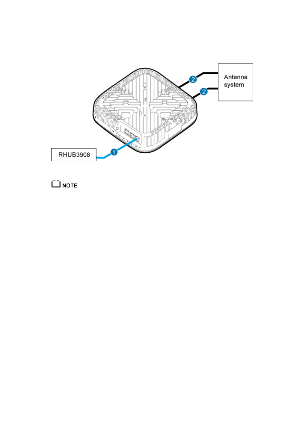
LampSite
Installation Guide
6 Installing a pRRU3901
Issue 08 (2014-12-30)
Huawei Proprietary and Confidential
Copyright © Huawei Technologies Co., Ltd.
77
standard of the pRRU3901 RF jumper, see (Optional) pRRU3901 RF Jumper of the
LampSite Hardware Description.
Figure 6-24 shows the cable connection when the pRRU3901 is configured with only one RF
Daughter Board.
Figure 6-24 pRRU3901 cable connection (1)
(1) Ethernet cable
(2) RF jumper
The Extender can be used to lengthen the distance between the RHUB3908 and the pRRU3901
connected using the Ethernet cable. If the Extender is used, the Ethernet cable is divided into two
parts, one between the RHUB3908 and the Extender and the other between the Extender and the
pRRU3901.
When two Ethernet cables are used to transmit CPRI signals, connect one end of the cables to the
CPRI_E0 and CPRI_E1 ports on the pRRU3901 panel and the other end to any two ports of
CPRI_E0 to CPRI_E7 on the RHUB3908 panel. This document describes signal transmission using
one Ethernet cable as an example.
Figure 6-25 shows the cable connection when the pRRU3901 is configured with two RF
Daughter Boards.

LampSite
Installation Guide
6 Installing a pRRU3901
Issue 08 (2014-12-30)
Huawei Proprietary and Confidential
Copyright © Huawei Technologies Co., Ltd.
78
Figure 6-25 pRRU3901 cable connection (2)
(1) Ethernet cable
(2) RF jumper
The Extender can be used to lengthen the distance between the RHUB3908 and the pRRU3901
connected using the Ethernet cable. If the Extender is used, the Ethernet cable is divided into two
parts, one between the RHUB3908 and the Extender and the other between the Extender and the
pRRU3901.
When two Ethernet cables are used to transmit CPRI signals, connect one end of the cables to the
CPRI_E0 and CPRI_E1 ports on the pRRU3901 panel and the other end to any two ports of
CPRI_E0 to CPRI_E7 on the RHUB3908 panel. This document describes signal transmission using
one Ethernet cable as an example.
Figure 6-26 shows the cable connection when the pRRU3901 is configured with two RF
Daughter Boards and one Wi-Fi daughter board.

LampSite
Installation Guide
6 Installing a pRRU3901
Issue 08 (2014-12-30)
Huawei Proprietary and Confidential
Copyright © Huawei Technologies Co., Ltd.
79
Figure 6-26 pRRU3901 cable connection (3)
(1) Ethernet cable
(2) RF jumper
The Extender can be used to lengthen the distance between the RHUB3908 and the pRRU3901
connected using the Ethernet cable. If the Extender is used, the Ethernet cable is divided into two
parts, one between the RHUB3908 and the Extender and the other between the Extender and the
pRRU3901.
When two Ethernet cables are used to transmit CPRI signals, connect one end of the cables to the
CPRI_E0 and CPRI_E1 ports on the pRRU3901 panel and the other end to any two ports of
CPRI_E0 to CPRI_E7 on the RHUB3908 panel. This document describes signal transmission using
one Ethernet cable as an example.
6.5.4 Cable Connections (LTE TDD)
This section describes the cable connections for a single pRRU3901 and multiple pRRU3901s
in LTE TDD mode.
Before installing the pRRU3901 cables, you must be aware of the following information:
The pRRU3901 can obtain power supply through the power over Ethernet (PoE).
For external antennas corresponding to RF daughter board 1, the TX port and RX port
are ANT0 and ANT1, respectively. For external antennas corresponding to RF daughter
board 2, the TX port and RX port are ANT2 and ANT3, respectively. For external
antennas corresponding to RF daughter board 3, the TX port and RX port are ANT4 and
ANT5, respectively.
The external antenna system is optional, and the pRRU3901 jumpers are not delivered.
By default, the pRRU3901s are configured with built-in antennas. If the external antenna
system is connected, the antenna system automatically switches to the external one. One
end of the pRRU3901 RF jumper is the SMA male connector, which is connected to the
external antenna TX/RX RF port on the pRRU3901. The other end of the pRRU3901 RF
jumper is the type N male connector, which is connected to the antenna system. For the

LampSite
Installation Guide
6 Installing a pRRU3901
Issue 08 (2014-12-30)
Huawei Proprietary and Confidential
Copyright © Huawei Technologies Co., Ltd.
80
standard of the pRRU3901 RF jumper, please see (Optional) pRRU RF Jumper of the
LampSite Hardware Description.
Figure 6-27 shows the cable connection when the pRRU3901 is configured with only one RF
Daughter Board.
Figure 6-27 pRRU3901 cable connection (1)
(1) Ethernet cable
(2) RF jumper
The Extender can be used to lengthen the distance between the RHUB and the pRRU connected using
the Ethernet cable. If the Extender is used, the Ethernet cable is divided into two parts, one between the
RHUB and the Extender and the other between the Extender and the pRRU.
6.5.5 pRRU3901 cable installation process
This section describes the process of installing pRRU3901 cables.
Figure 6-28 shows the process of installing pRRU3901 cables.
Figure 6-28 pRRU3901 cable installation process

LampSite
Installation Guide
6 Installing a pRRU3901
Issue 08 (2014-12-30)
Huawei Proprietary and Confidential
Copyright © Huawei Technologies Co., Ltd.
81
6.5.6 Installing an Ethernet Cable
This section describes how to install an Ethernet cable.
Prerequisites
Ethernet cables are not delivered, and they must be prepared onsite. You need to use a
network cable tester to test the Ethernet cable connection.
The Ethernet cable must be of Category 5e (enhanced) or higher. In addition, its
cross-sectional area must be 24 AWG or larger and frame spread rating must be CM or
higher. With the internal PoE module providing power, the maximum length of an
Ethernet cable is 100 m. With the Extender, the distance of the pRRU3901 and
RHUB3908 can be extended by the Extender up to a total distance of 200 m.
Context
The Ethernet cable has the following functions:
Provides power supply for the pRRU3901 when the cable connects the CPRI_E0 port on
the pRRU3901 to the RHUB.
Transmits CPRI signals between an RHUB3908 and a pRRU3901.
Provides Wi-Fi services for the pRRU3901 when the cable connects the GE port on the
pRRU3901 with three transmission ports to the AC.
Using the CPRI_E1 port on the pRRU3901 has the same Ethernet cable connection to the
RHUB3908 as using the CPRI_E0 port. The following section describes the connection using
the CPRI_E0 port.
Procedure
1. Make the Ethernet cables.
1. Assemble an RJ45 connector and an Ethernet cable by following instructions in
Assembling the Unshielded RJ45 Connector and the Ethernet Cable of Installation
Reference.
Follow pin assignment instructions described in section Ethernet Cable in LampSite Hardware
Description to assemble the unshielded RJ45 connector and the Ethernet cable. Otherwise, the
transmission signal quality deteriorates and CPRI links may be disconnected.
2. Check whether the made RJ45 connector is qualified by following instructions in
Checking the Appearance of Metal Contact Strips.
3. To complete the assembly of the other end, repeat Step 1.1 and Step 1.2.
4. Check whether the touch points on the connectors at both ends are normally conducted
and well contacted and whether the connections are correct by following instructions in
Testing the Connection of Assembled Cables of Installation Reference.
Step 2 Install an Ethernet cable between an RHUB3908 and a pRRU3901.
1. Remove the dustproof cap of the CPRI_E0 port on the pRRU3901.
2. Connect the RJ45 connector at one end of the Ethernet cable to the CPRI_E0 port on the
pRRU3901 panel.
3. Optional: Connect the RJ45 connector at the other end of the Ethernet cable to the
output port of the Extender. Then, connect the RJ45 connector at one end of another
Ethernet cable to the input port of the Extender.

LampSite
Installation Guide
6 Installing a pRRU3901
Issue 08 (2014-12-30)
Huawei Proprietary and Confidential
Copyright © Huawei Technologies Co., Ltd.
82
4. Connect the RJ45 connector at the other end of the Ethernet cable to any port ranging
from CPRI_E0 to CPRI_E7 on the RHUB3908 panel based on the engineering design, as
shown in Figure 6-29.
Step 3 Optional: Install the Ethernet cable between the pRRU3901 and the AC. This operation is
required when the pRRU3901 with three transmission ports is configured with a Wi-Fi
daughter board.
1. Remove the dustproof cap of the GE port on the pRRU3901.
2. Connect the RJ45 connector at one end of the Ethernet cable to the GE port on the
pRRU3901 panel.
3. Connect the RJ45 connector at the other end of the Ethernet cable to the transmission
port of the AC based on the engineering design, as shown in Figure 6-29.
Figure 6-29 Installing an Ethernet cable
(1) Ethernet cable
(2) GE port on the pRRU3901
(3) CPRI_E0 port on the pRRU3901
The pRRU3901 can have two transmission ports plus one PWR port or three transmission ports (plus
one PWR port or no PWR port), requiring the same installation operations. This section uses the
pRRU3901 with three transmission ports no PWR port as an example.
----End
Follow-up Procedure
1. Route the cable, and then use a cable tie to bind the cable. For details, see 6.5.1
Requirements for Cable Layout.
2. Label the installed cable. For details, see section 8.3 Attaching an L-Shaped Label.
6.5.7 Installing pRRU3901 Jumpers (Optional)
pRRU3901 jumpers transmit radio frequency signals. One end of the jumper is the SMA
straight male connector, and the other end is the type N connector.
Context
If the RF jumper is provided by the customer, the jumper must not be lower than the
RG316 specifications. In addition, the jumpers can be used after they are checked by
Huawei engineers.
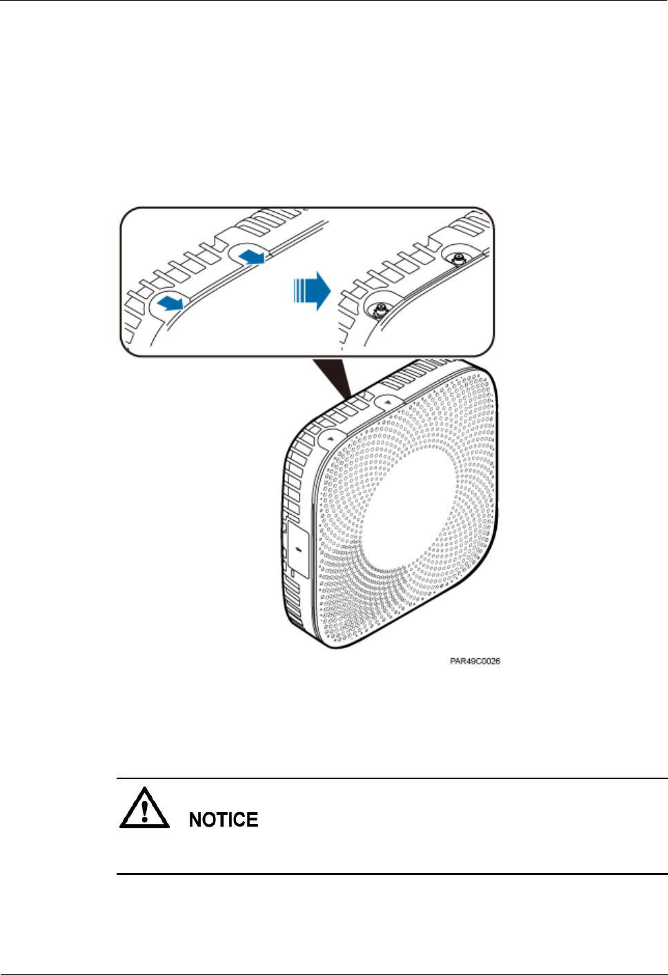
LampSite
Installation Guide
6 Installing a pRRU3901
Issue 08 (2014-12-30)
Huawei Proprietary and Confidential
Copyright © Huawei Technologies Co., Ltd.
83
pRRU3901s can be connected to external whip antennas or external remote antennas
(through pRRU3901 RF jumpers). Whip antennas are delivered optionally. RF jumpers
are not delivered.
Procedure
1. Expose the SMA female connector by removing the pRRU3901 antenna housing, as
shown in Figure 6-30.
Figure 6-30 Removing the pRRU3901 antenna housing
Step 2 Use a torque wrench with a torque of 0.6 N•m to connect the SMA straight male connector on
a jumper to the ANT port on the pRRU3901 panel.
Tighten it with hands, and then use a torque wrench to tighten it with a rotational speed of less
than or equal to 2.4 rpm to tighten it.
Step 3 Connect the type N female connector of the jumper to the type N male connector of the RF
feeder connected to the built-in antenna.

LampSite
Installation Guide
6 Installing a pRRU3901
Issue 08 (2014-12-30)
Huawei Proprietary and Confidential
Copyright © Huawei Technologies Co., Ltd.
84
Tighten the feeder close to the type N connector to ensure that the jumper is not tightened. In
this way, the connectors on both ends of a jumper are not affected by the external force.
Figure 6-31 Installing jumpers between the pRRU3901 and external antennas
----End
Follow-up Procedure
1. Route the cable, and then use a cable tie to bind the cable. For details, see 6.5.1
Requirements for Cable Layout.
2. Label the installed cable. For details, see section 8.3 Attaching an L-Shaped Label.
6.6 Checking the pRRU3901 Hardware Installation
pRRU3901 hardware installation checking includes hardware and cable installation checking.
Table 6-8 lists the hardware installation checking items.
Table 6-8 Hardware installation checking list
No.
Item
1
Ensure that the pRRU3901 is not grouned.
2
The position for each device conforms to the engineering design and meets the
space requirement.
3
Ensure that the pRRU3901 is properly installed.
4
The surface of the pRRU3901 is neat and clean. The external paint is intact.

LampSite
Installation Guide
6 Installing a pRRU3901
Issue 08 (2014-12-30)
Huawei Proprietary and Confidential
Copyright © Huawei Technologies Co., Ltd.
85
No.
Item
The labels, tags, and nameplates are correct, legible, and complete.
Table 6-9 lists the check items of the signal cable connection.
Table 6-9 Checklist for the signal cable connection
No.
Item
1
The connectors of the signal cables must securely connected.
2
The connectors of the signal cables are intact.
3
The signal cables are intact.
4
The cable ties are evenly spaced. The signal cables are bound neatly with cable
ties to proper tightness, and arranged at even intervals in the same direction.
5
The extra length of the cable ties is cut and removed. The cut surfaces of the
indoor cables are smooth and have no sharp edges.
6
The cable layout facilitates maintenance and expansion.
7
Correct and clear labels are attached to both ends of the signal cables.
Table 6-10 lists the checking items for other cable connections.
Table 6-10 Checklist for other cable connections
No.
Item
1
The connectors of the other cables must securely connected.
2
Labels on the cables are legible and bound based on the engineering
requirements. The cables must be bound tightly and neatly. The sheaths of the
cables must not be damaged.
3
Positions for routing the cables must meet requirements of the engineering
design.
6.7 Powering on the pRRU3901
This section describes the power-on check on the pRRU3901 after the pRRU3901 hardware is
installed and checked.
Procedure
1. Power on the pRRU3901.

LampSite
Installation Guide
6 Installing a pRRU3901
Issue 08 (2014-12-30)
Huawei Proprietary and Confidential
Copyright © Huawei Technologies Co., Ltd.
86
The pRRU3901 can be powered in PoE mode. The RHUB3908 adopts the PoE power supply
to provide power for the pRRU3901 over the CPRI_E0 port.
Step 2 Power on the pRRU3901. Wait 3 to 5 minutes, check the status of the RUN indicator on the
pRRU3901.
If the RUN Indicator...
Because...
Then...
Steady on
There is power input, but the
board is faulty.
Power off the power supply,
rectify the fault, and power on
the pRRU3901.
Steady off
There is no power input, or an
alarm is reported on the
board.
Power off the power supply
and check the power input. If
no fault is found after the
pRRU3901 is powered off,
clear the fault on the board,
and power on the pRRU3901.
On for 1s and off for 1s
The device works properly.
End this operation.
On for 0.125s and off for
0.125s
The software of the board is
loading.
Wait five minutes for the
software to be successfully
loaded. If the software is
loading five minutes later,
shut off the power supply.
Check whether the data
configuration file is correct.
After the fault is rectify,
power on the pRRU3901
again.
----End

LampSite
Installation Guide
7 Installing the Extender (Optional)
Issue 08 (2014-12-30)
Huawei Proprietary and Confidential
Copyright © Huawei Technologies Co., Ltd.
87
7 Installing the Extender (Optional)
This section describes the Extender installation process.
Context
When an RHUB3908 and a pRRU need extended install, use extender. With the Extender, the
distance of the pRRU and RHUB3908 can be extended by the Extender up to a total distance
of 200 m.
The Extender can be installed on a wall or ceiling in the same mode. This section describes
wall-mounted installation as an example.
Only space above and under the Extender is required to be reserved when installing the
Extender. The recommended space for installing the Extender is described as follows:
At least 150 mm above the Extender is reserved for cabling.
At least 150 mm under the Extender is reserved for cabling.
Procedure
1. Use a marker to mark the two anchor points according to inter-hole spacing, as shown in
Figure 7-1.
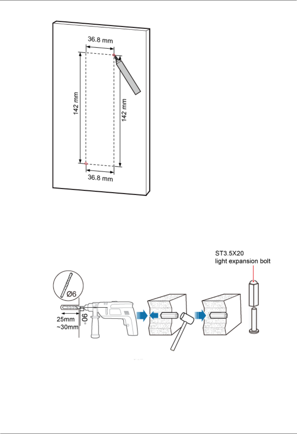
LampSite
Installation Guide
7 Installing the Extender (Optional)
Issue 08 (2014-12-30)
Huawei Proprietary and Confidential
Copyright © Huawei Technologies Co., Ltd.
88
Figure 7-1 Marking anchor points
Step 2 Drill holes at the anchor points, and install expansion bolt assemblies, as shown in Figure 7-2.
The diameter of the hole is 6 mm, and the depth is 25 mm to 30 mm.
Figure 7-2 Drilling holes and installing expansion bolts
Step 3 Place the Extender in the corresponding position and use an M4 Phillips screwdriver to
tighten the screws to 1.4 N•m, as shown in Figure 7-3.

LampSite
Installation Guide
7 Installing the Extender (Optional)
Issue 08 (2014-12-30)
Huawei Proprietary and Confidential
Copyright © Huawei Technologies Co., Ltd.
89
Figure 7-3 Installing Extender
----End
LampSite
Installation Guide
8 Appendix
Issue 08 (2014-12-30)
Huawei Proprietary and Confidential
Copyright © Huawei Technologies Co., Ltd.
90
8 Appendix
About This Chapter
This chapter describes reference information during installation.
8.1 MAC Collection Template
This section describes the MAC collection template for a pRRU3901 with three transmission
ports.
8.2 LampSite Engineering Label
This section describes the content and presents the exterior of LampSite engineering labels.
8.3 Attaching an L-Shaped Label
This section describes the procedure and precautions to be taken for attaching an L-shaped
label.
8.4 Installing RF Daughter Boards on a pRRU3901 (in Capacity Expansion Scenarios)
This section describes the procedures for installing RF daughter boards on a pRRU3901.
8.1 MAC Collection Template
This section describes the MAC collection template for a pRRU3901 with three transmission
ports.
The MAC collection template is used to record the installation position, MAC address of the
site at the initial installation stage to facilitate subsequent commissioning and maintenance.
Table 8-1 shows the MAC collection template.
Table 8-1 MAC collection template
No.
Site
Number
Site Name
WIFI MAC
Location Information
Sampl
e
01
pRRU3901
xx floor, xx building, xx
mansion

LampSite
Installation Guide
8 Appendix
Issue 08 (2014-12-30)
Huawei Proprietary and Confidential
Copyright © Huawei Technologies Co., Ltd.
91
No.
Site
Number
Site Name
WIFI MAC
Location Information
Note: The MAC collection template is essential to the engineering stage and
subsequent maintenance, especially when multiple devices are installed at a short
distance. This is because the template defines the radio network to access. Maintain
this template with caution.
8.2 LampSite Engineering Label
This section describes the content and presents the exterior of LampSite engineering labels.
Label Content
The LampSite engineering labels include the RHUB3908 power label, RHUB3908 ground
label, RHUB3908 alarm or monitoring label, RHUB3908 optical transmission label, and
RHUB3908 network transmission label, the pRRU3901 power label, pRRU3901 network
transmission label, pRRU3901 antenna label. The engineering labels are used for LampSite
units RHUB3908 and pRRU3901 for indoor scenarios.
By default, blank labels are delivered for LampSite and must be filled in onsite. Table 8-2
describes the content of engineering labels.
Table 8-2 LampSite Engineering Label Content
NE
Label Content
Description
Corresponding
port on the base
station
RHUB390
8
Power
label
RHUB390
8x
PWR
Label for the RHUB3908x
power cable.
x specifies the number of
RHUB3908s and cannot
exceed the maximum
RHUB3908 number
supported by the
networking.
PWR

LampSite
Installation Guide
8 Appendix
Issue 08 (2014-12-30)
Huawei Proprietary and Confidential
Copyright © Huawei Technologies Co., Ltd.
92
NE
Label Content
Description
Corresponding
port on the base
station
Ground
label
RHUB390
8x
PGND
Label for the RHUB3908x
ground cable.
x specifies the number of
RHUB3908s and cannot
exceed the maximum
RHUB3908 number
supported by the
networking.
Alarm or
monitorin
g label
RHUB390
8x
EXT_AL
M
Label for the RHUB3908x
alarm cable.
x specifies the number of
RHUB3908s and cannot
exceed the maximum
RHUB3908 number
supported by the
networking.
EXT-ALM
Optical
transmissi
on label
RHUB390
8x
BBU/RH
UB3908a/
RHUB390
8b
Label for the RHUB3908x
CPRI cable.
x specifies the number
of RHUB3908s and
cannot exceed the
maximum RHUB3908
number supported by
the networking.
a can be set to 0 or 1. 0
and 1 respectively
correspond to CPRI0
port and CPRI1 port of
the upper-level
RHUB3908.
b can be set to 0 or 1. 0
and 1 respectively
correspond to CPRI0
port and CPRI1 port of
the lower-level
RHUB3908.
CPRI0 or CPRI1
Network
transmissi
on label
RHUB390
8x
CPRI_Ea
Label for the RHUB3908x
Ethernet cable.
x specifies the number
of RHUB3908s and
cannot exceed the
maximum RHUB3908
number supported by
the networking.
a can be set to 0 or 1. 0
and 1 respectively
CPRI_E0 to
CPRI_E7
LampSite
Installation Guide
8 Appendix
Issue 08 (2014-12-30)
Huawei Proprietary and Confidential
Copyright © Huawei Technologies Co., Ltd.
93
NE
Label Content
Description
Corresponding
port on the base
station
correspond to CPRI_E0
port and CPRI_E1 port
of the pRRU3901.
pRRU390
1
Power
label
pRRU390
1y
PWR
Label for the pRRU3901y
power cable.
y specifies the number of
pRRU3901s and cannot
exceed the maximum
pRRU3901 number
supported by the
networking.
PWR or CPRI_E0
Network
transmissi
on label
pRRU390
1y
CPRI_Ea
Label for the pRRU3901y
Ethernet cable.
y specifies the number
of pRRU3901s and
cannot exceed the
maximum pRRU3901
number supported by
the networking.
a can be set to 0 to 7,
which respectively
correspond to CPRI_E0
port to CPRI_E7 port of
the RHUB3908.
CPRI_E0 or
CPRI_E1
Antenna
label
pRRU390
1y
ANTa
Label for the pRRU3901y
RF Jumper.
y specifies the number
of pRRU3901s and
cannot exceed the
maximum pRRU3901
number supported by
the networking.
a can be set to 0 to 5,
which respectively
correspond to ANT0
port and ANT5 port of
the pRRU3901.
ANT0 to ANT5

LampSite
Installation Guide
8 Appendix
Issue 08 (2014-12-30)
Huawei Proprietary and Confidential
Copyright © Huawei Technologies Co., Ltd.
94
In the label, RHUB3908 and pRRU3901 identify the specific LampSite NEs.
If only one RHUB3908 is deployed, mark it as RHUB39080 on the label. If multiple RHUB3908s
are deployed, mark them in ascending sequence, beginning with RHUB39080.
If only one pRRU3901 is deployed, mark it as pRRU39010 on the label. If multiple pRRU3901s are
deployed, mark them in ascending sequence, beginning with pRRU39010.
For details about the maximum number of RHUB3908s and pRRU3901s in the LampSite solution,
see Typical Configurations in LampSite Technical Description.
Label Structure
Using the RHUB3908 power label as an example, Figure 8-1 shows the structure of a
LampSite engineering label.
Figure 8-1 Label structure
8.3 Attaching an L-Shaped Label
This section describes the procedure and precautions to be taken for attaching an L-shaped
label.
Context
This section applies to Huawei sign plate labels. If other engineering labels in
accordance with local standards are used on site, follow the local standards for attaching
sign plate labels.
In the LampSite solution, blank L-Shaped engineering labels are delivered by default.
The L-shaped label is usually used for the signal cable, E1/T1 cable, optical cable, and
power cable. The description in this section takes the Ethernet cable in a base station as
an example.
Procedure
1. Obtain the engineering label to be attached from the whole set of the L-shaped
engineering labels, as shown in Figure 8-2.

LampSite
Installation Guide
8 Appendix
Issue 08 (2014-12-30)
Huawei Proprietary and Confidential
Copyright © Huawei Technologies Co., Ltd.
95
Figure 8-2 Engineering label to be attached
Step 2 Attach the long end of the engineering label to the cable in the position 20 mm away from the
connector, and then turn over the long end along the adhesive face. Ensure that the edges of
the turned-over engineering label are in a line, as shown in Figure 8-3.
By default, the label is attached in the position 20 mm away from the connector. If required, you can
change the position to make installation faster and more efficient. Consistency and neatness, however,
must be maintained.
Step 3 Adhere the long end to the labeling area. Ensure that the spacing between the cable and the
labeling area is 2 mm to 3 mm.
Figure 8-3 Adhering the long end to the labeling area
Step 4 Turn over the labeling area along the adhesive face from the bottom, and then finish attaching
the engineering label, as shown in Figure 8-4 and Figure 8-5. Ensure that the edges of the
turned-over labeling area are in a line.
Figure 8-4 Turning over the labeling area along the adhesive face

LampSite
Installation Guide
8 Appendix
Issue 08 (2014-12-30)
Huawei Proprietary and Confidential
Copyright © Huawei Technologies Co., Ltd.
96
Figure 8-5 Attached engineering label
Step 5 Fill in the attached blank label by referring to 8.2 LampSite Engineering Label.
----End
8.4 Installing RF Daughter Boards on a pRRU3901 (in
Capacity Expansion Scenarios)
This section describes the procedures for installing RF daughter boards on a pRRU3901.
Context
An RF daughter Board is only installed in product pRRU3901 AWS+PCS+WIFInd
pRRU3901 AWS+PCS+WIFI, and it transmits, receives, and processes RF signals.
The preferred slot for an RF daughter board depends on the mode of the RF daughter board.
Figure 8-6 shows the slot for installing the RF daughter boards.
Figure 8-6 Slot for installing the RF daughter boards
Unless otherwise specified, LTE mode in this document refers to LTE TDD and LTE FDD.
This section describes how to install an RF daughter board in slot S2 as an example.
Procedure
Step 1 Instruct the network operator to block the pRRU3901.

LampSite
Installation Guide
8 Appendix
Issue 08 (2014-12-30)
Huawei Proprietary and Confidential
Copyright © Huawei Technologies Co., Ltd.
97
The LampSite solution supports immediate block, idle block, and delayed block. Application of idle
block and delayed block produces the same effect as application of immediate block.
On the UMTS side, log in to the LMT and run the BLK BRD command to block the RF
daughter board.
On the LTE side, log in to the LMT and run the BLK BRD command to block the RF
daughter board.
Step 2 Power off the pRRU3901.
Powering off the pRRU3901 interrupts all the services carried on the pRRU3901.
Step 3 Wear ESD gloves.
Take proper ESD protection measures. For example, wear ESD gloves to prevent electrostatic
damage to the boards, modules, or electronic components.
Step 4 Use an M4 Phillips screwdriver to loosen the Phillips screw on the pRRU3901 housing.
Wrench and remove the housing from the installation position of the Phillips screw hole, as
shown in Figure 8-7.
Figure 8-7 Removing the pRRU3901 housing
Either Phillips screws or protection screws can be used for installing the pRRU3901 housing and the
RF daughter board, requiring the same installation operations. This section uses Phillips screws as an
example to describe the installation operations.
Keep the Phillips screw secure for future use.
Step 5 Install an RF daughter board in slot S2.
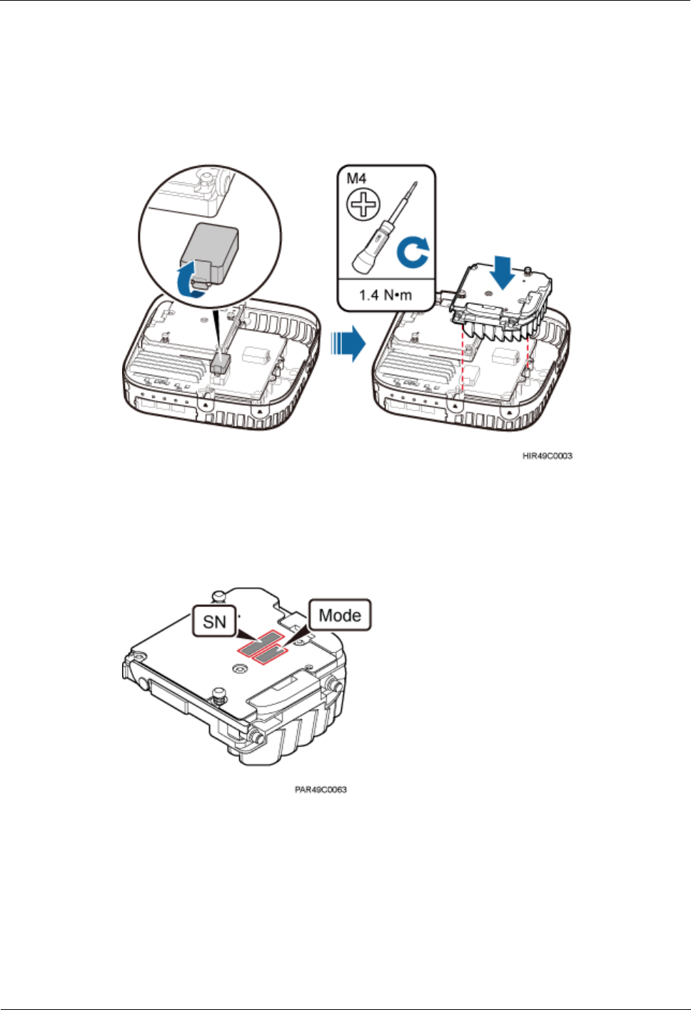
LampSite
Installation Guide
8 Appendix
Issue 08 (2014-12-30)
Huawei Proprietary and Confidential
Copyright © Huawei Technologies Co., Ltd.
98
3. Remove the protective cover from the RF daughter board connector of slot S2.
4. Level the handles of an RF daughter board of the required mode, and insert the handles
separately in the two dowels of slot S2, and use the M4 Phillips screwdriver to tighten
the two Phillips screws on the RF daughter board with a torque of 1.4 N•m, as shown in
Figure 8-8.
Figure 8-8 Installing the RF daughter board in slot S2
Step 6 Remove the SN label and mode label on the surface of the RF daughter board, as shown in
Figure 8-9.
Figure 8-9 Removing the SN label and mode label
Step 7 Attach the removed SN label to the corresponding position for S2 label on the nameplate side
of the pRRU3901 housing and the mode label to a position (for the label of slot S2 on the side
of the pRRU3901 housing) between antenna ports ANT2 and ANT3, as shown in Figure 8-10.
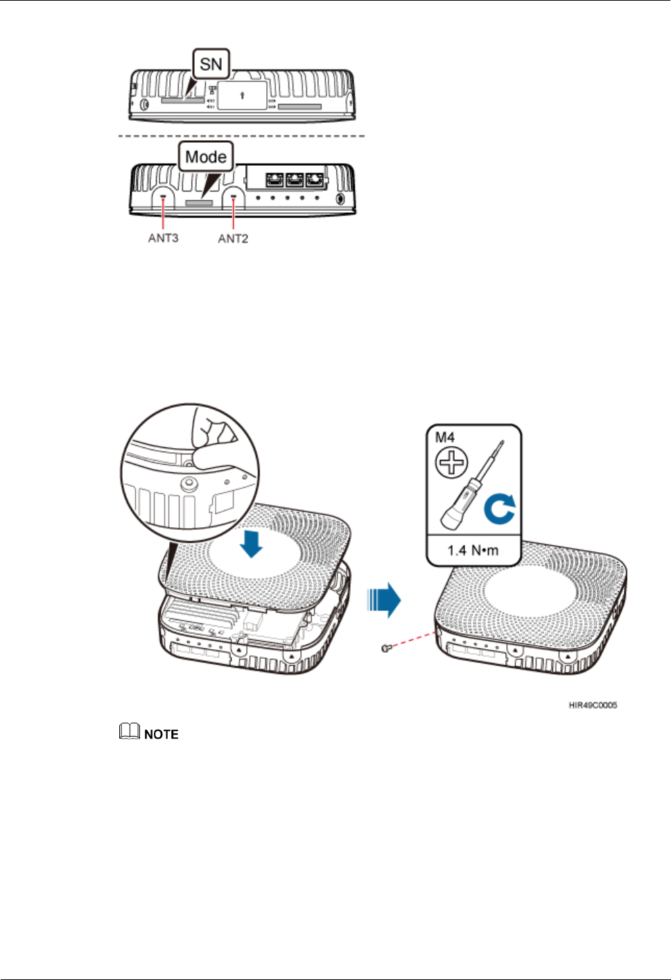
LampSite
Installation Guide
8 Appendix
Issue 08 (2014-12-30)
Huawei Proprietary and Confidential
Copyright © Huawei Technologies Co., Ltd.
99
Figure 8-10 Attaching the SN label and mode label
Step 8 Close the pRRU3901 housing and tamp each side of the housing until a click is heard. Ensure
that the groove gaps between the front and back housings are evenly distributed. Use the M4
Phillips screwdriver to tighten the Phillips screw on the housing with a torque of 1.4 N•m, as
shown in Figure 8-11.
Figure 8-11 Installing the pRRU3901 housing
The Phillips screw is the one removed and kept in Step 4.
Step 9 Power on the pRRU3901.
Step 10 Instruct the network operator to unblock the pRRU3901.
On the UMTS side, log in to the NodeB LMT and run the UBL BRD command to
unblock the RF daughter board of the pRRU3901.
On the LTE side, log in to the eNodeB LMT and run the UBL BRD command to unblock
the RF daughter board of the pRRU3901.
Step 11 Take off the ESD gloves and pack up all the tools.

LampSite
Installation Guide
8 Appendix
Issue 08 (2014-12-30)
Huawei Proprietary and Confidential
Copyright © Huawei Technologies Co., Ltd.
100
----End