Huawei Technologies PRU01P2G6 pico Remote Radio Unit User Manual 13
Huawei Technologies Co.,Ltd pico Remote Radio Unit 13
UserManual.wiki
>
Huawei Technologies
>
PRU01P2G6 User Manual
13_User Manual
Navigation menu
Upload a User Manual
Namespaces
Wiki Guide
HTML
PDF
Info
Views
User Manual
Discussion / Help
Navigation

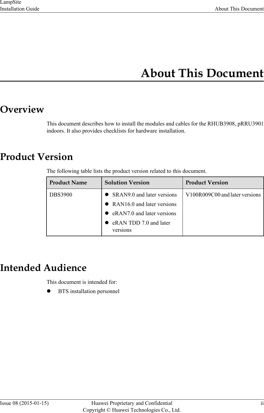
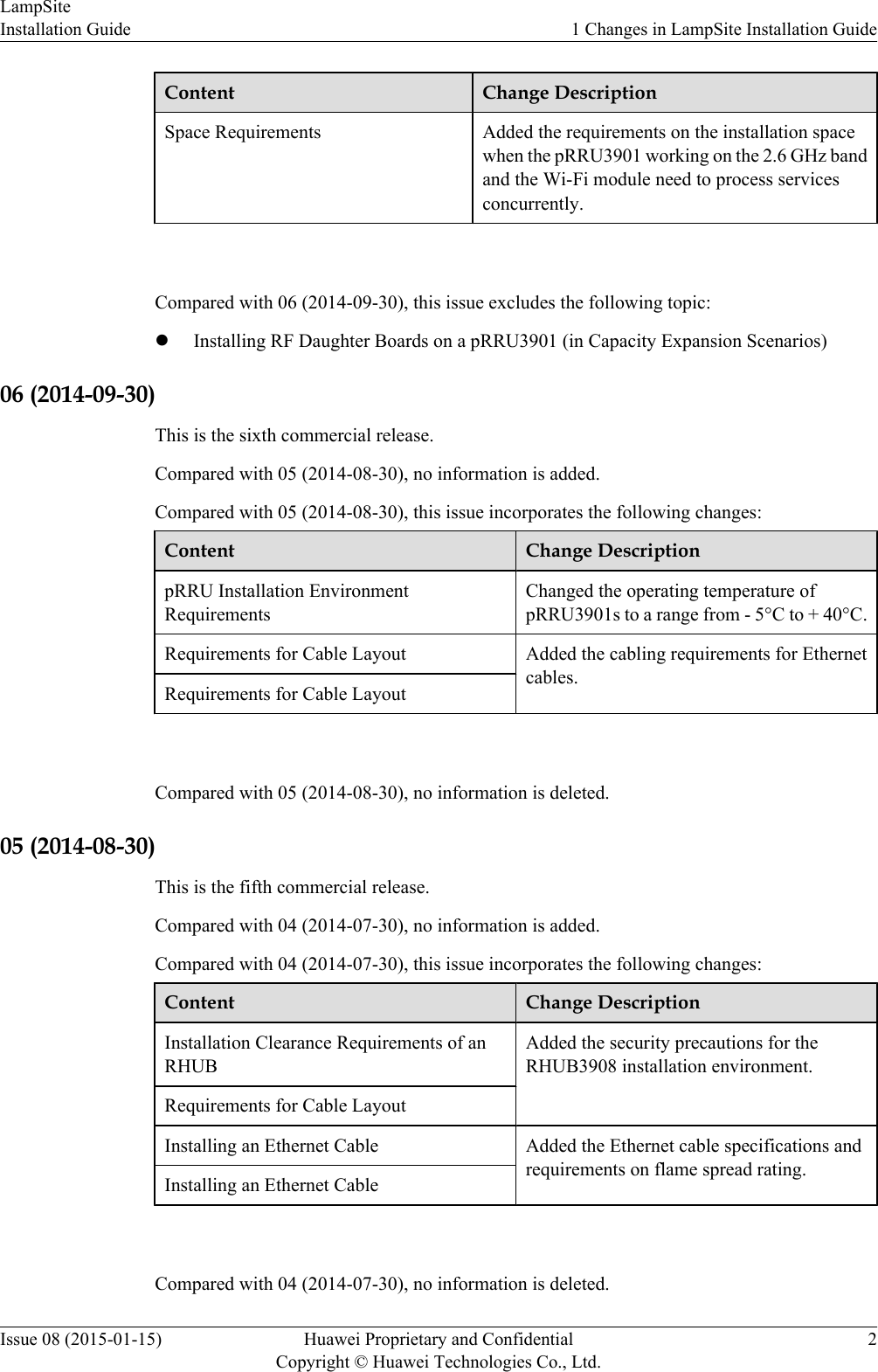
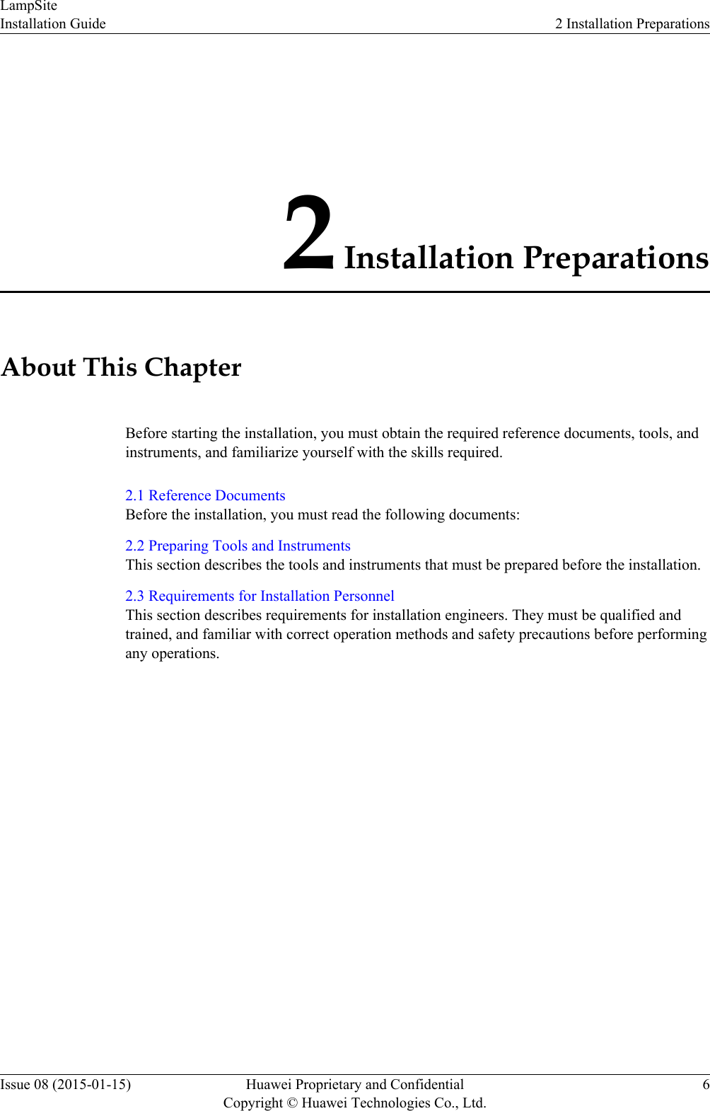
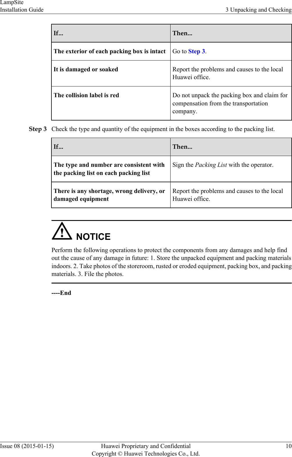
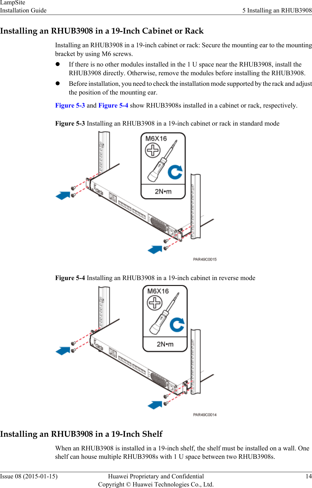
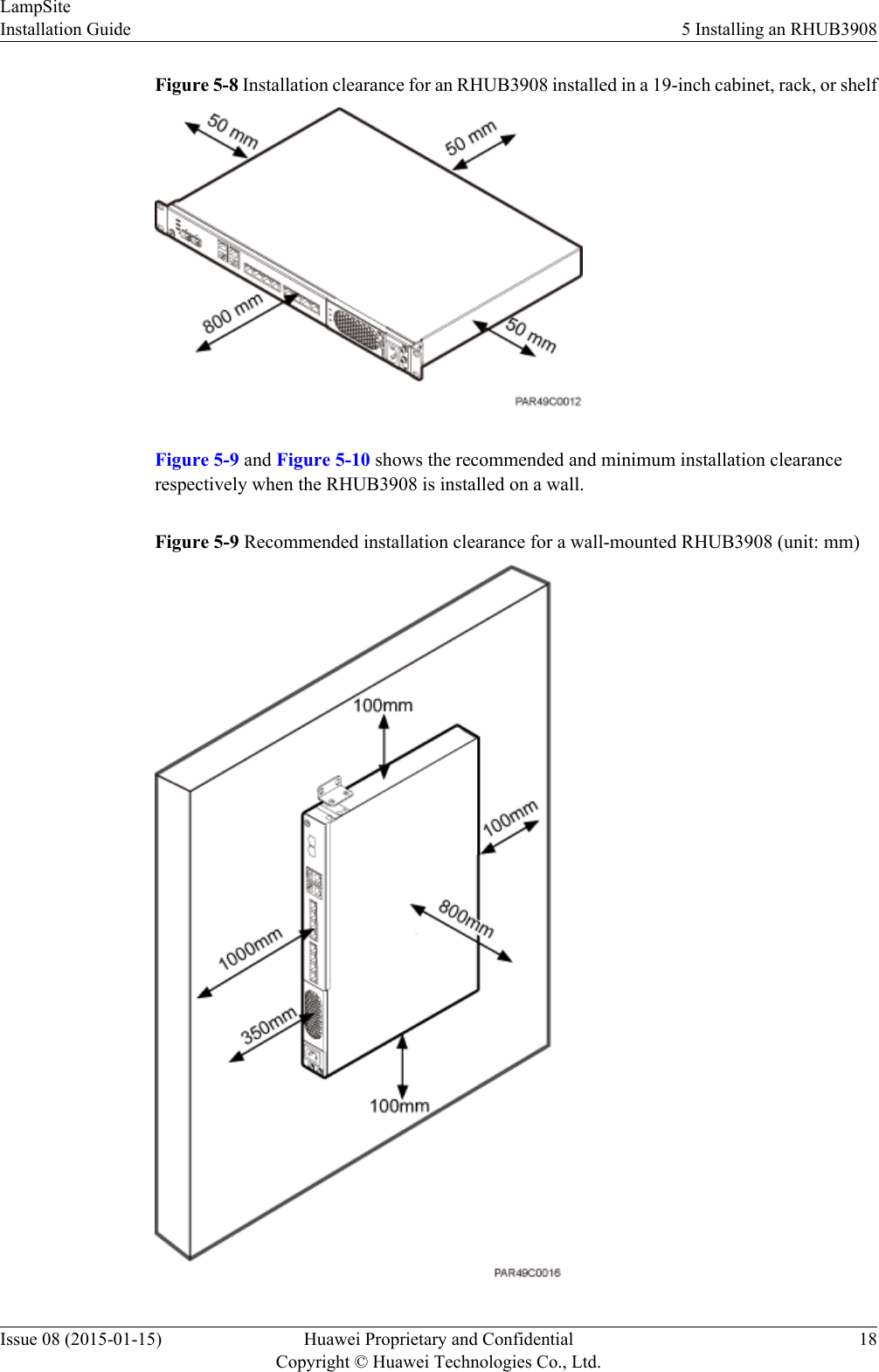
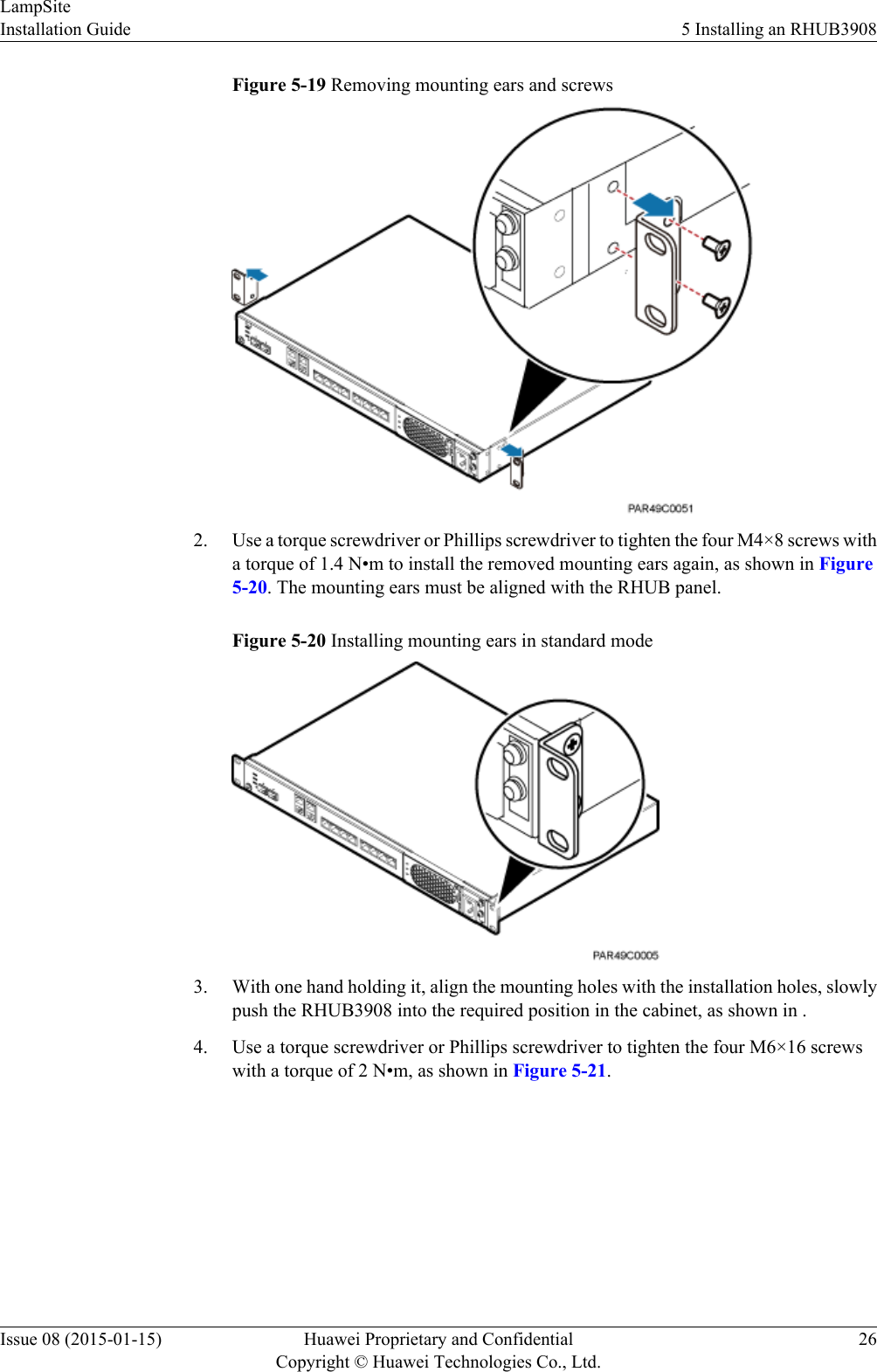
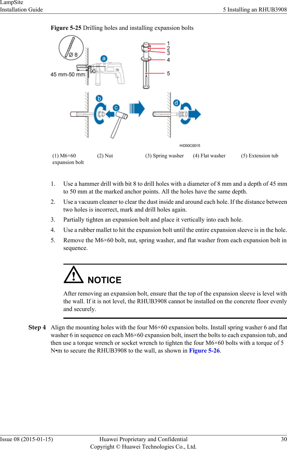
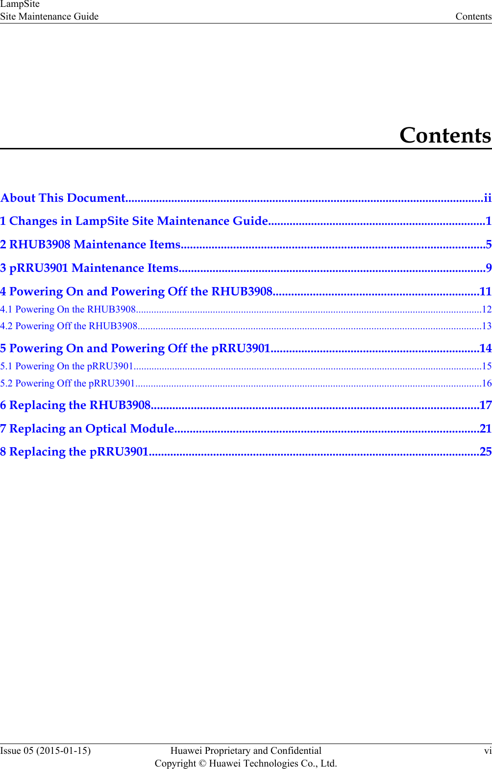
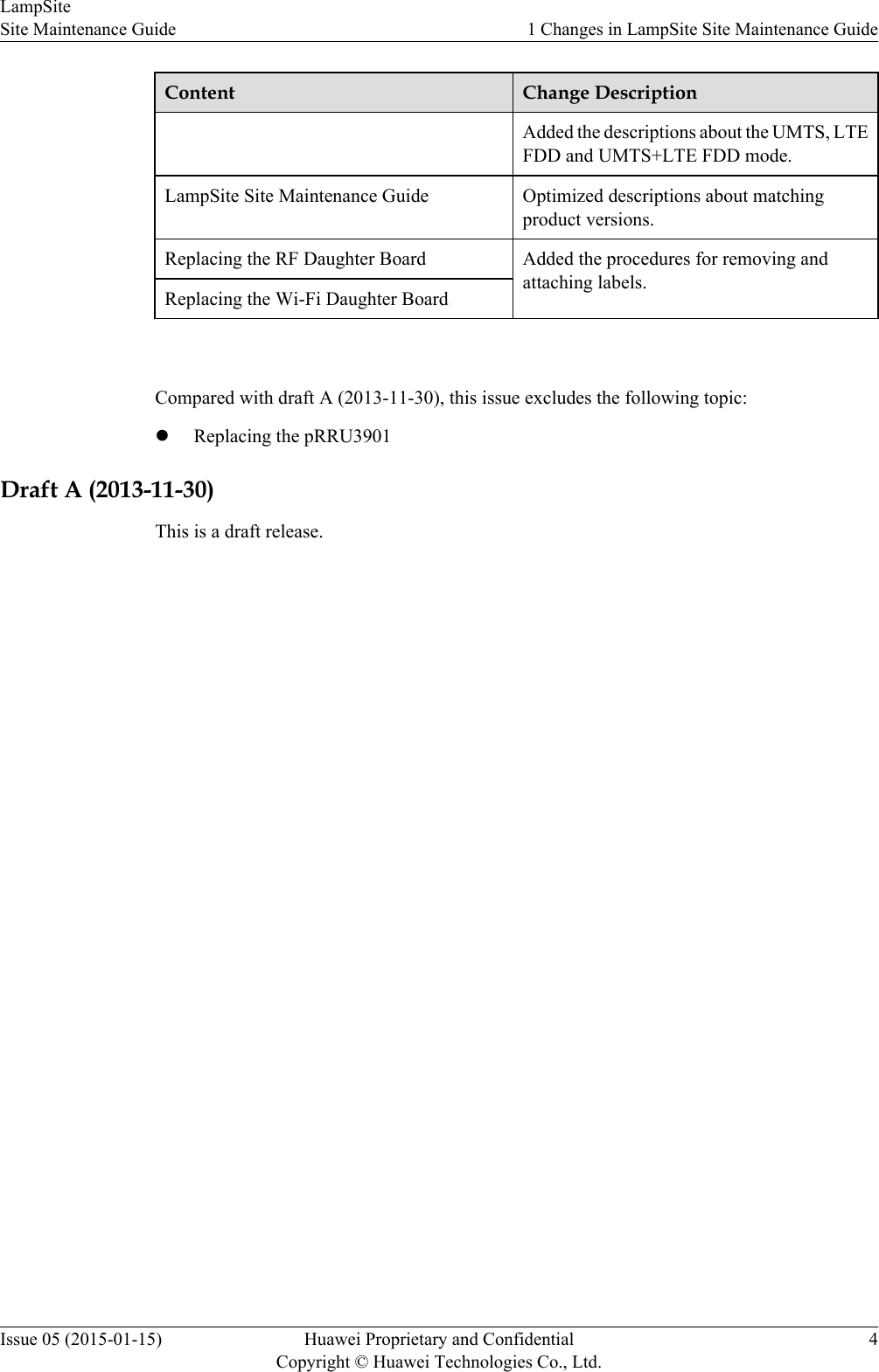
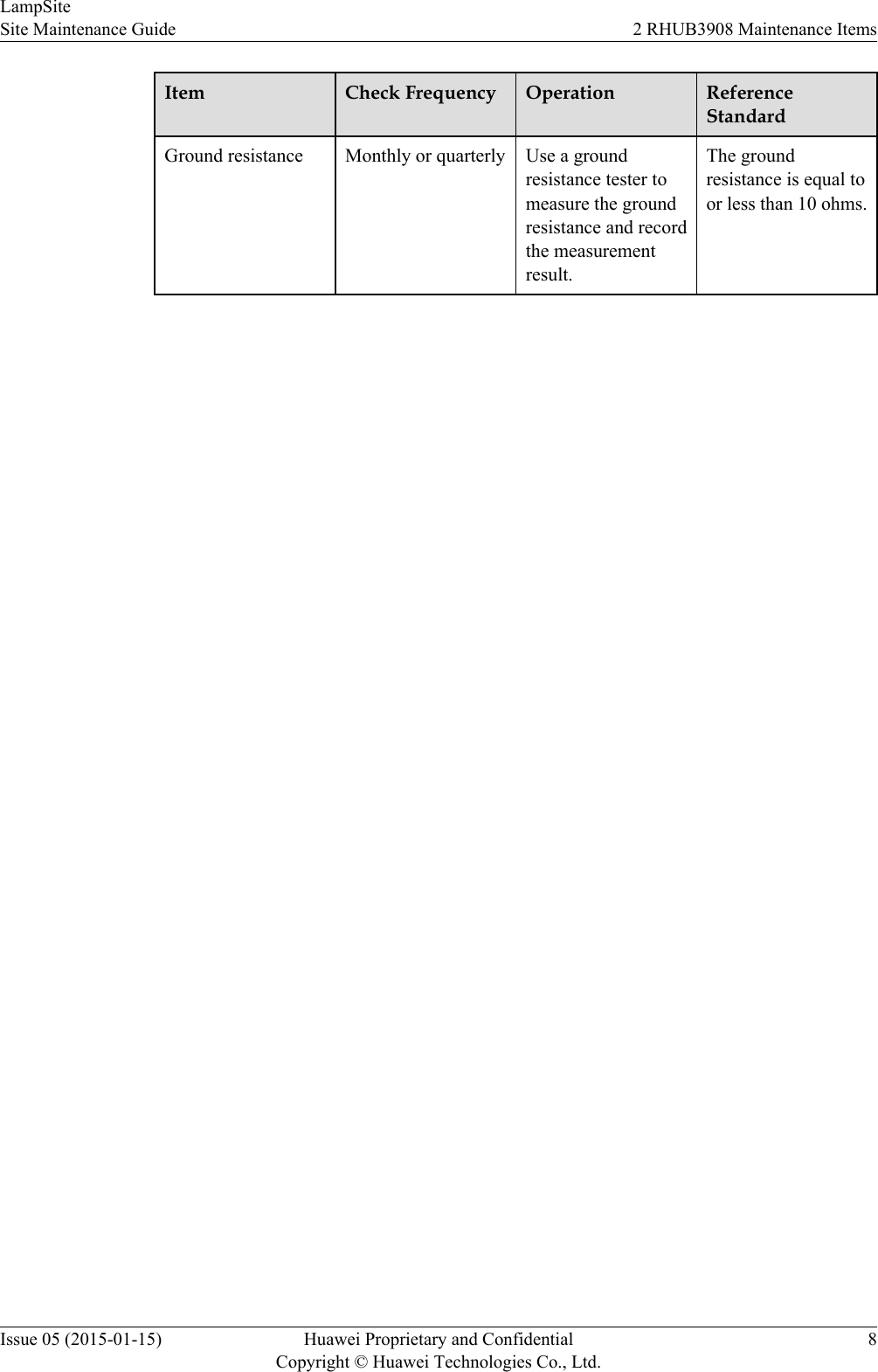
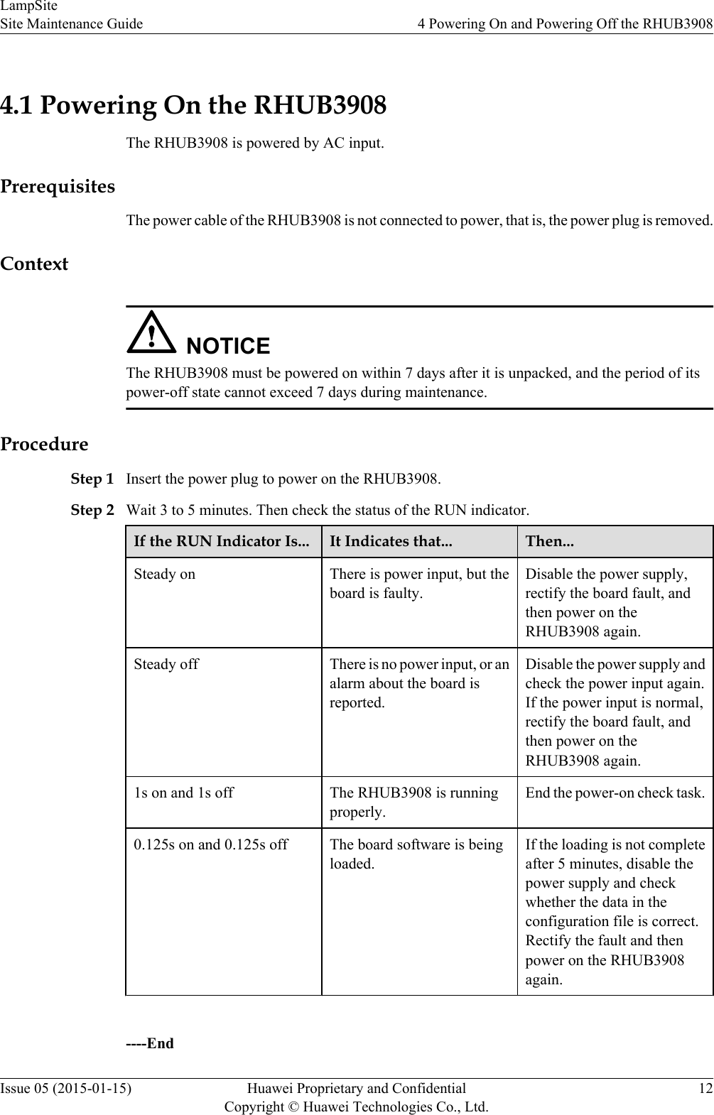
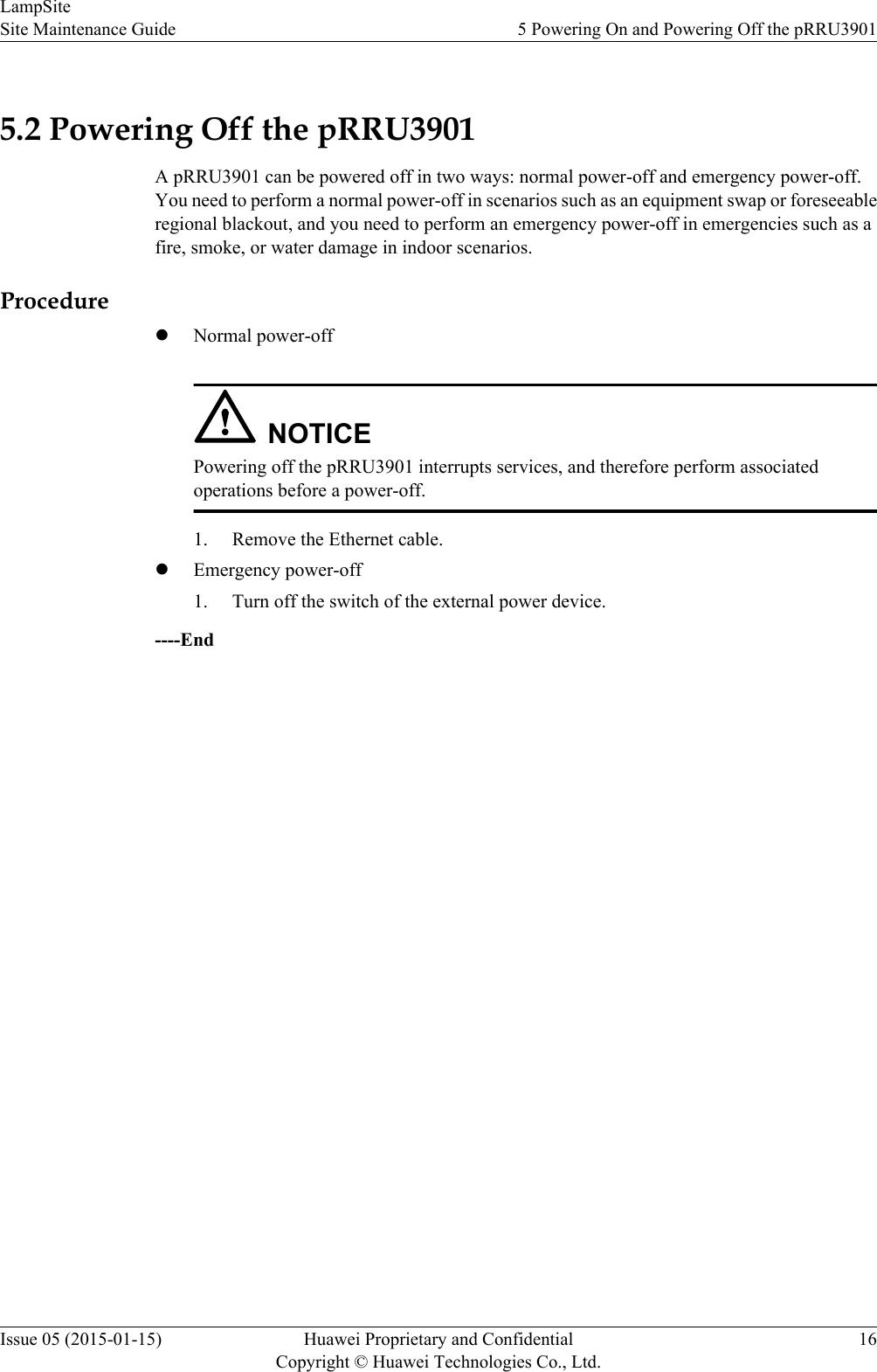
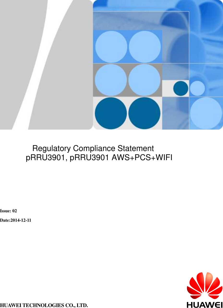
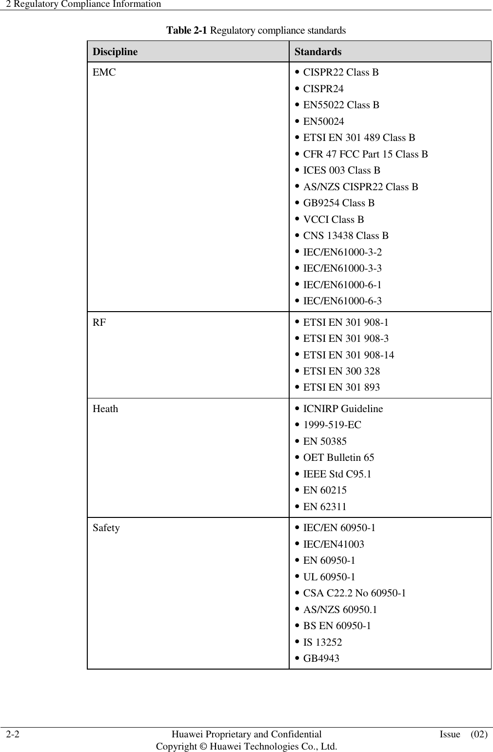
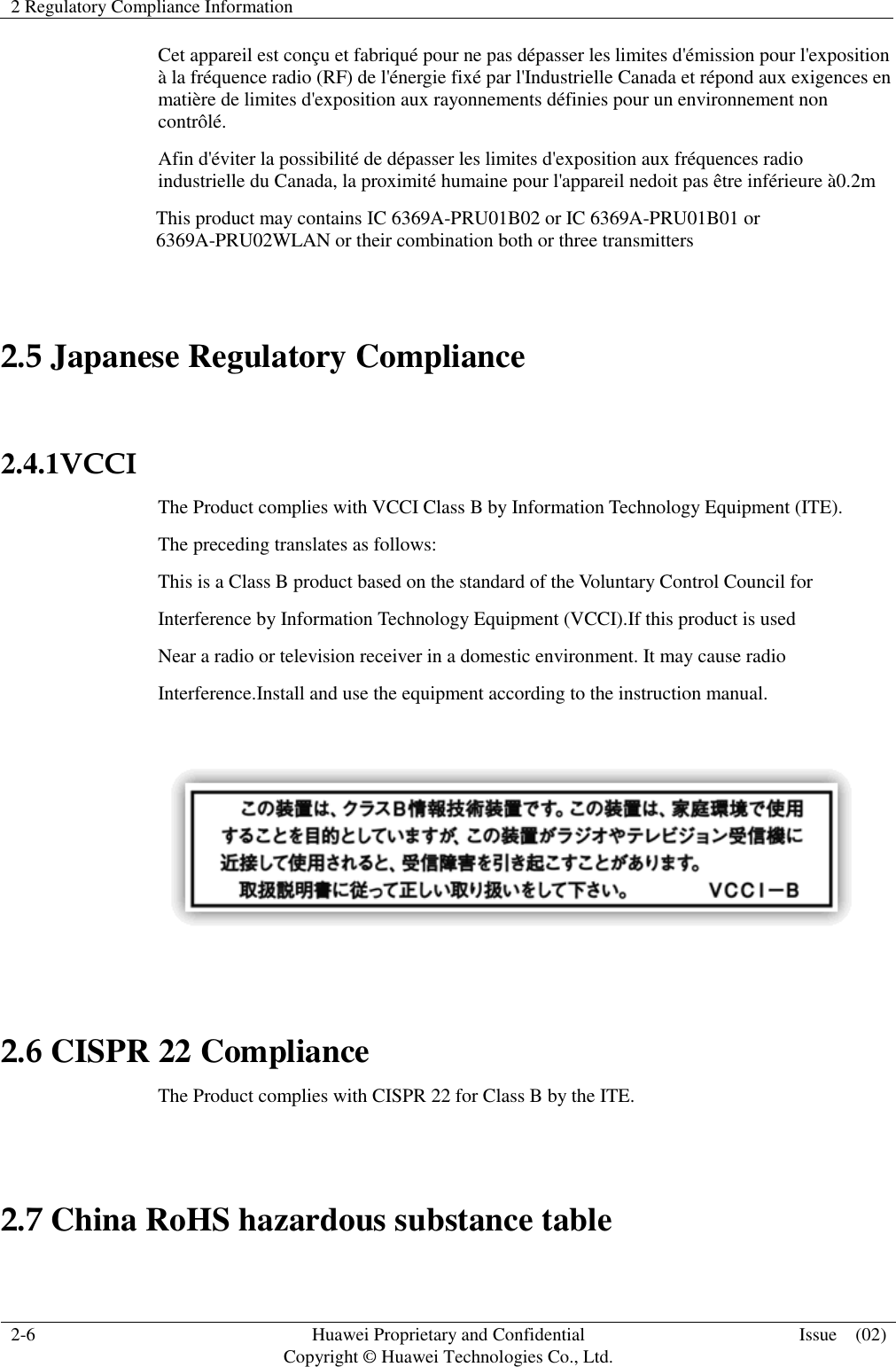
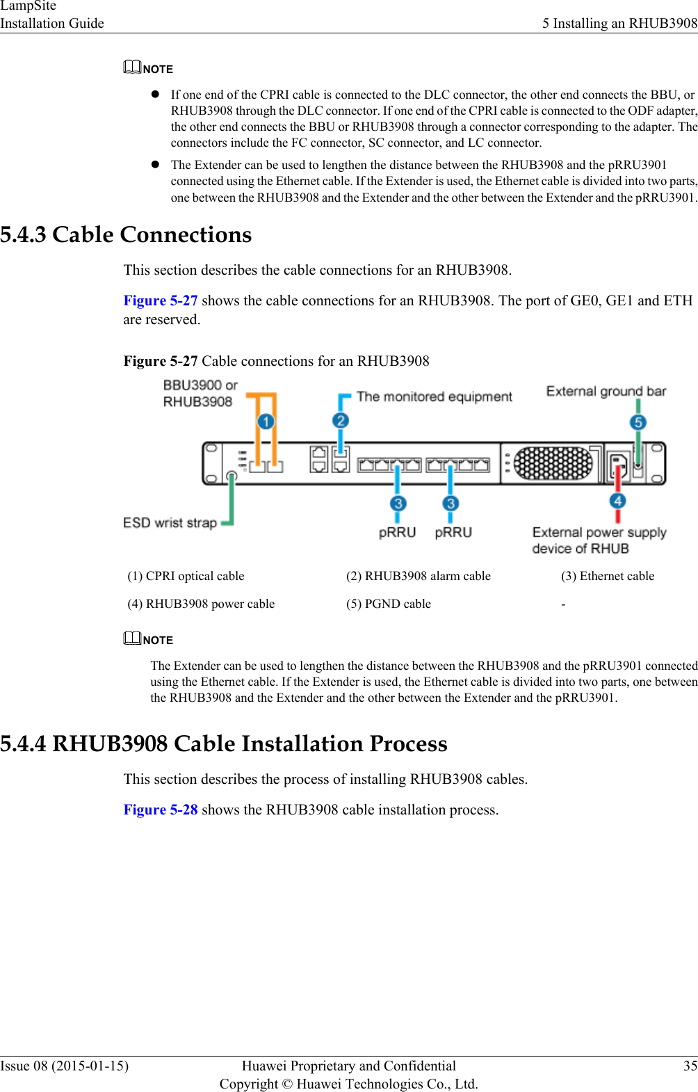
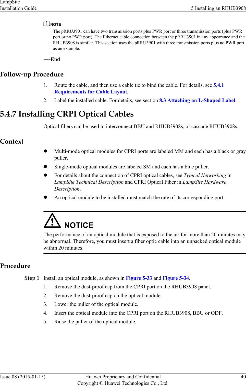
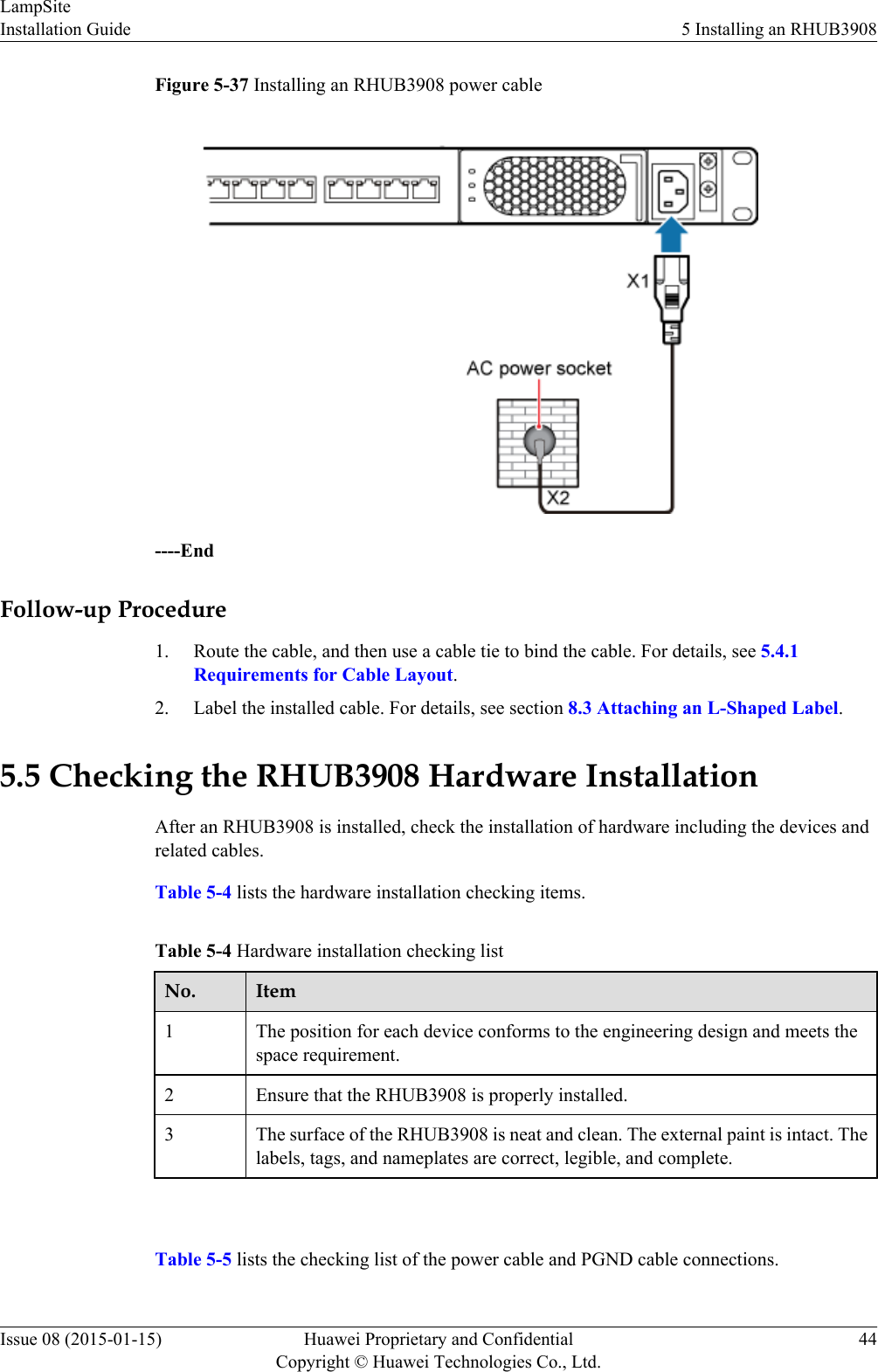
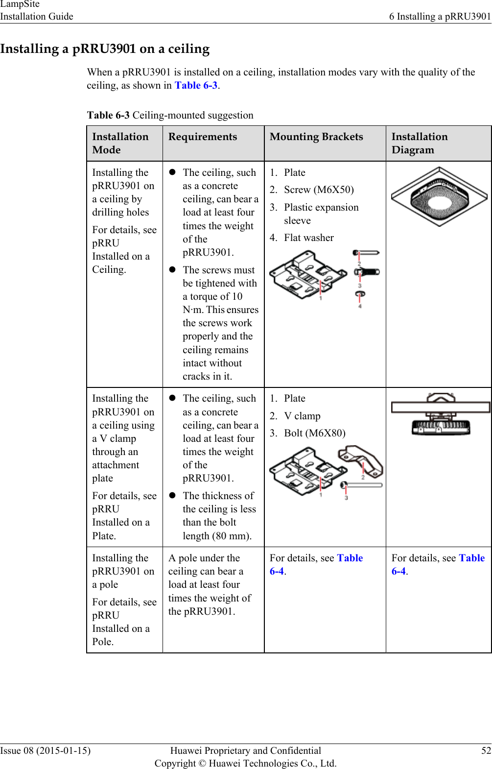
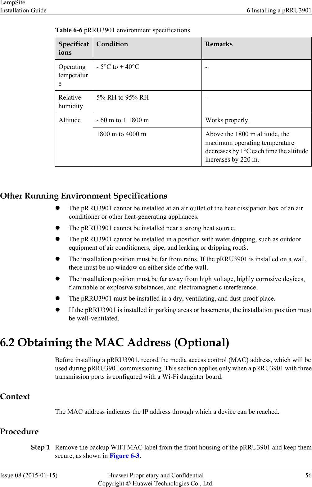
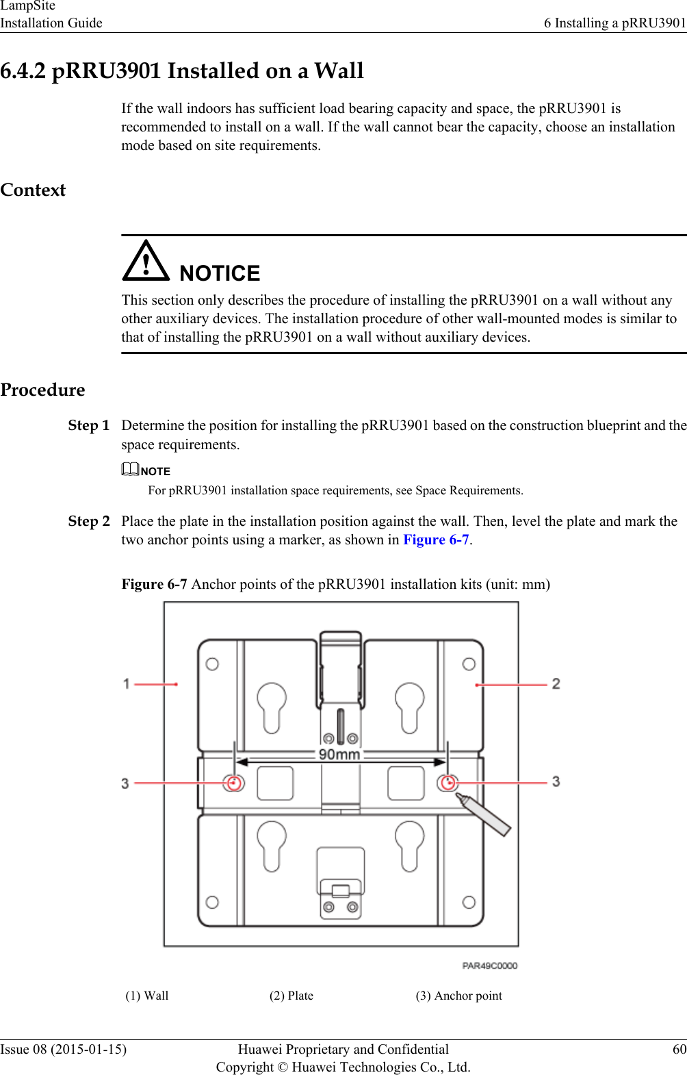
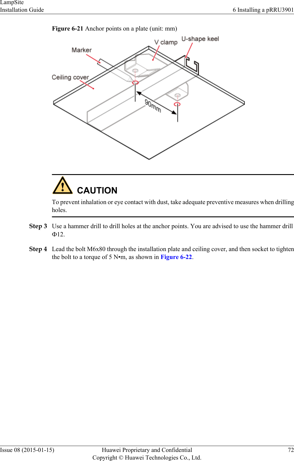
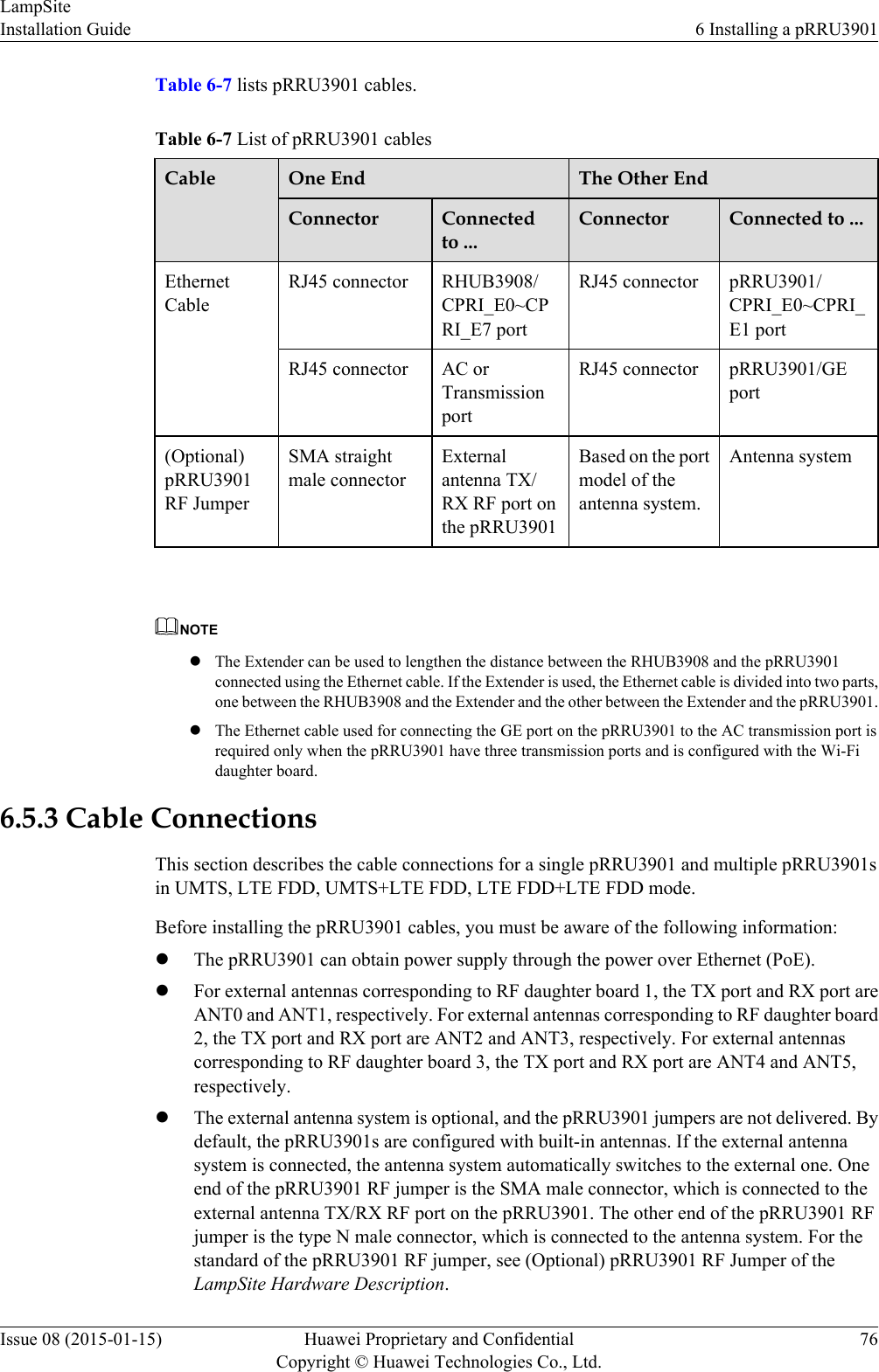
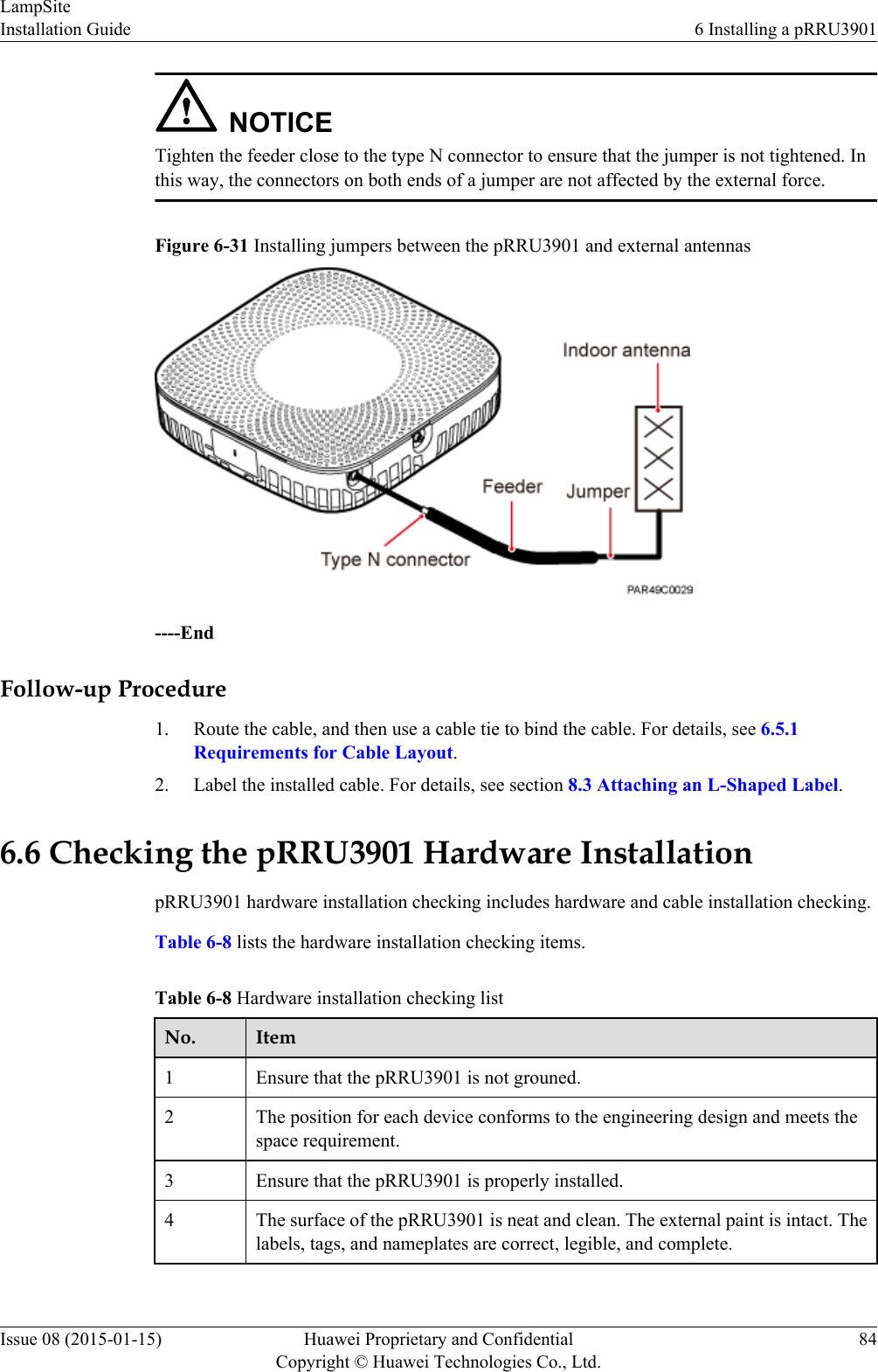
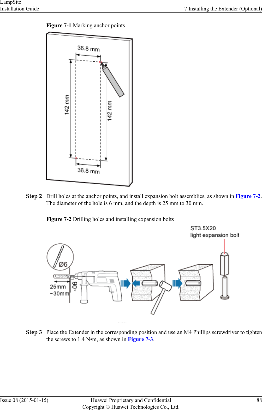
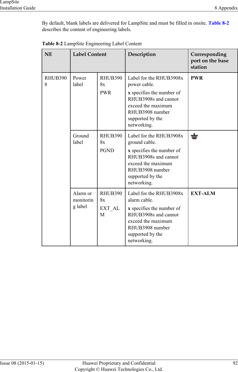
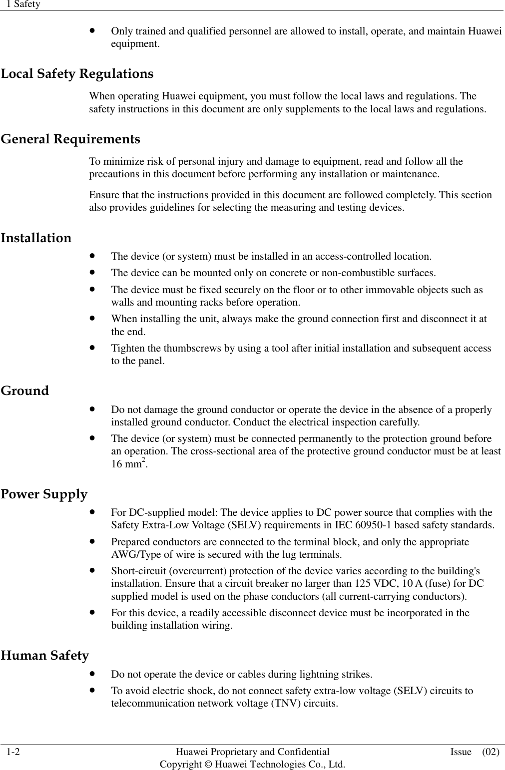
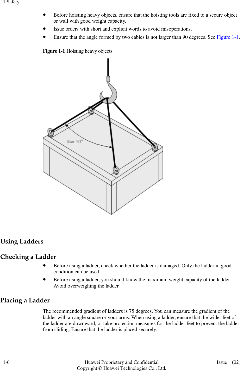
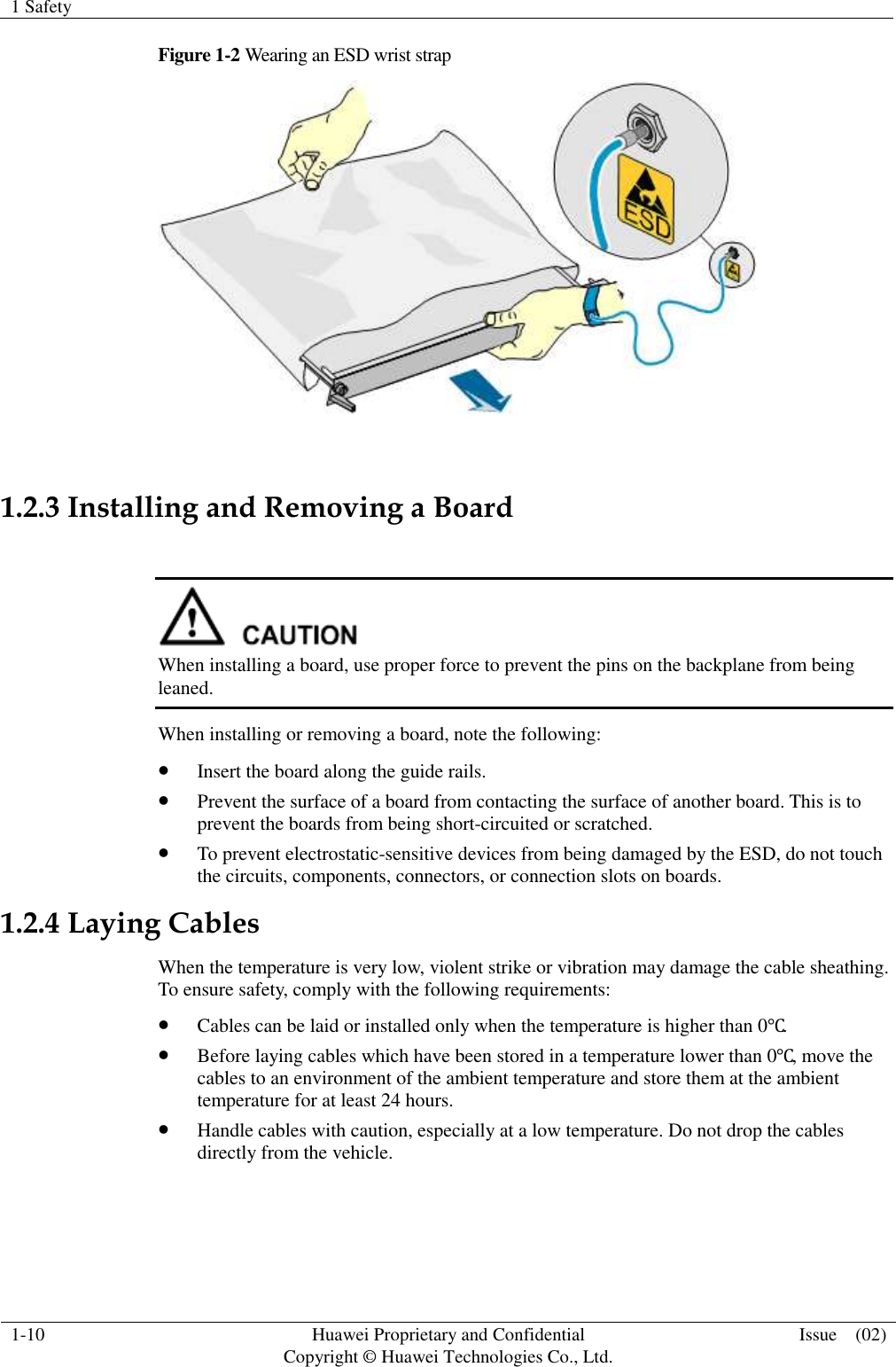
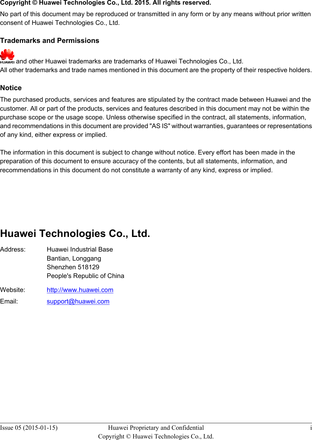
![5.4.2 RHUB3908 Cable ListThis section describes the connector types and connections of the RHUB3908 cables.Table 5-2 lists RHUB3908 cables.Table 5-2 RHUB3908 cable listCable One End The Other EndConnector Connectedto...Connector Connected to...PGND cable OT terminal (M4,6 mm2 [0.009 in.2])Ground screwson theRHUB3908OT terminal(M6, 6 mm2[0.009 in.2])Ground terminalon the externalground barRHUB3908PowerSupply CableC13 femaleconnectorAC powerinput socket onthe RHUB39083-pin connector External powerinput socketCPRI OpticalFiberDLC connector CPRI port onthe LBBP,WBBP orUBBP in theBBUDLC connector CPRI0 or CPRI1port on theRHUB3908CPRI0 orCPRI1 port onthe RHUB3908DLC connector CPRI0 or CPRI1port on theRHUB3908CPRI port onthe LBBP,WBBP orUBBP in theBBUFC connector,SC connector, orLC connectorODFCPRI0 orCPRI1 port onthe RHUB3908FC connector,SC connector, orLC connectorODFEthernetCableRJ45 connector CPRI_E0~CPRI_E7 port onthe RHUB3908RJ45 connector CPRI_E0~CPRI_E1 port on thepRRU3901(Optional)RHUB3908Alarm CableRJ45 connector EXT_ALMport on theRHUB3908Bare end Alarm signal portof the monitoredequipment LampSiteInstallation Guide 5 Installing an RHUB3908Issue 08 (2015-01-15) Huawei Proprietary and ConfidentialCopyright © Huawei Technologies Co., Ltd.34](https://usermanual.wiki/Huawei-Technologies/PRU01P2G6/User-Guide-2703608-Page-39.png)
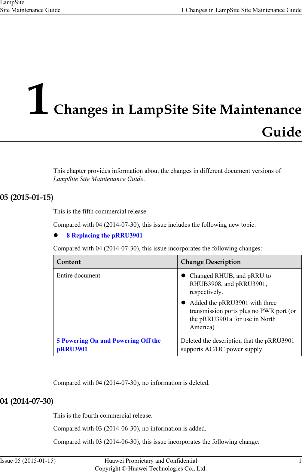
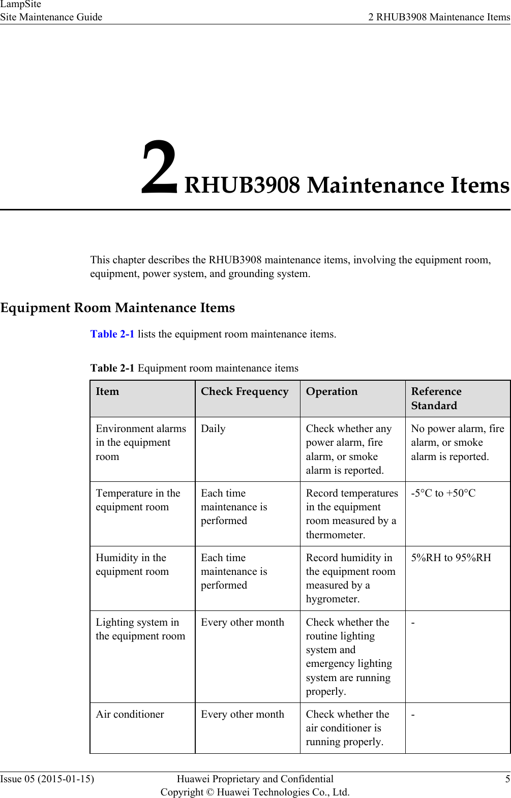
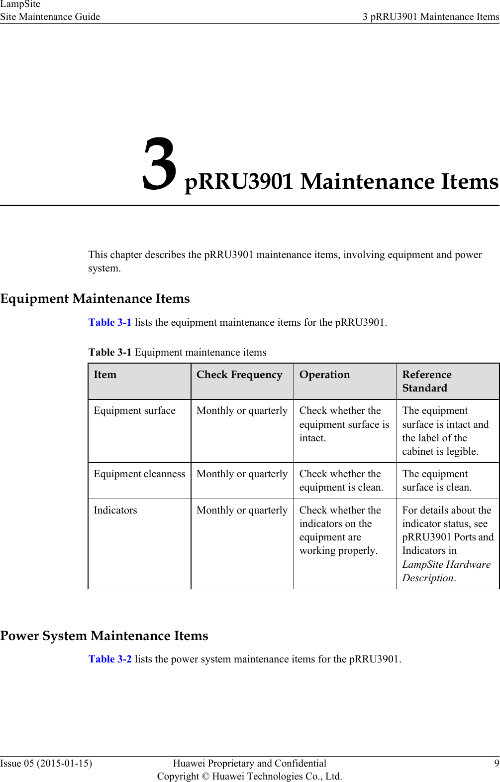
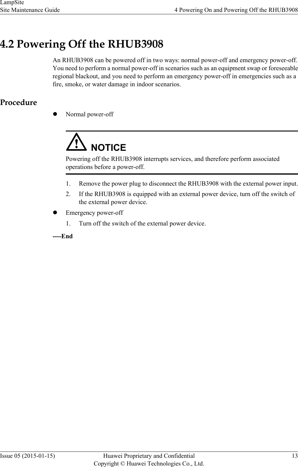
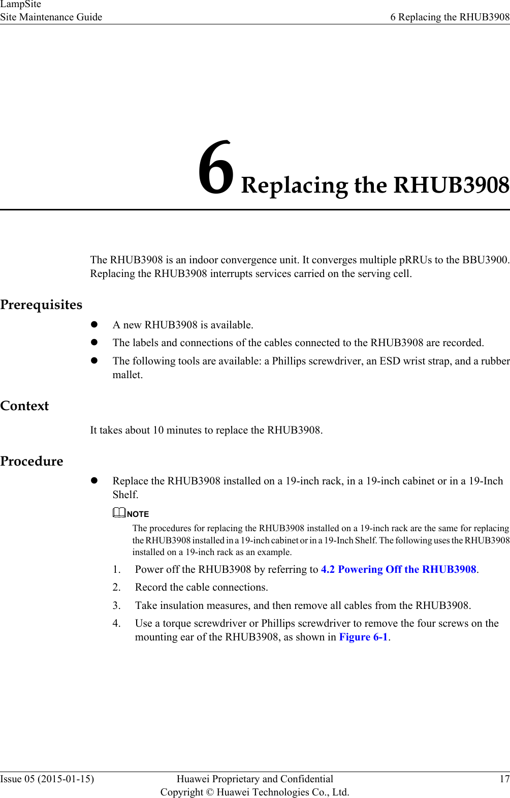
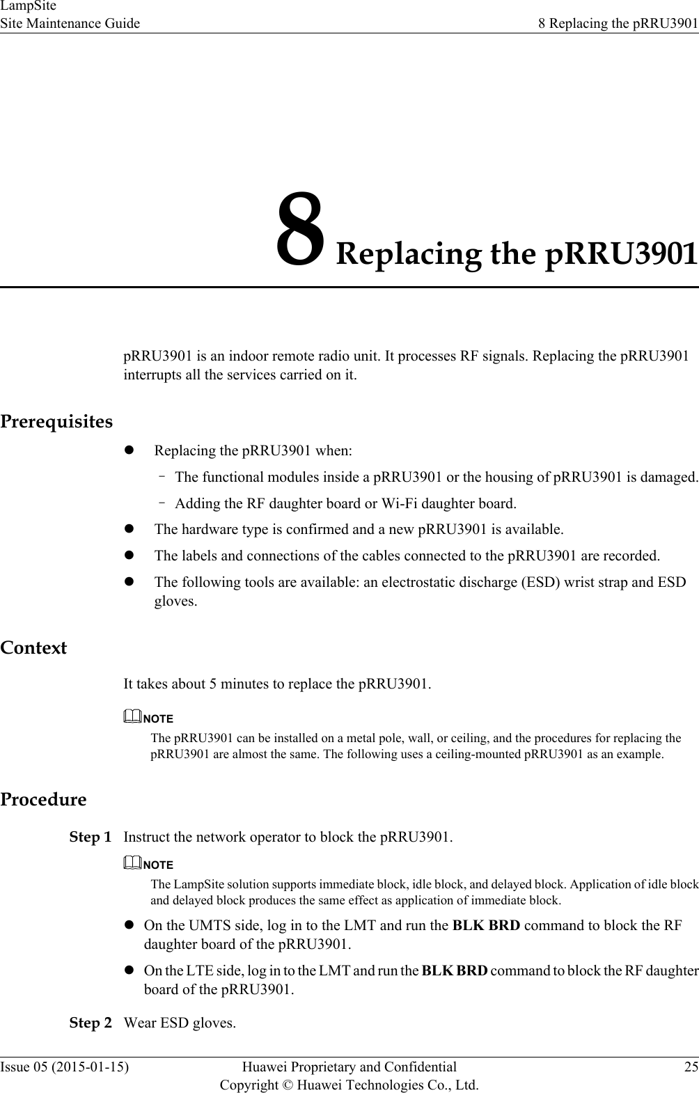
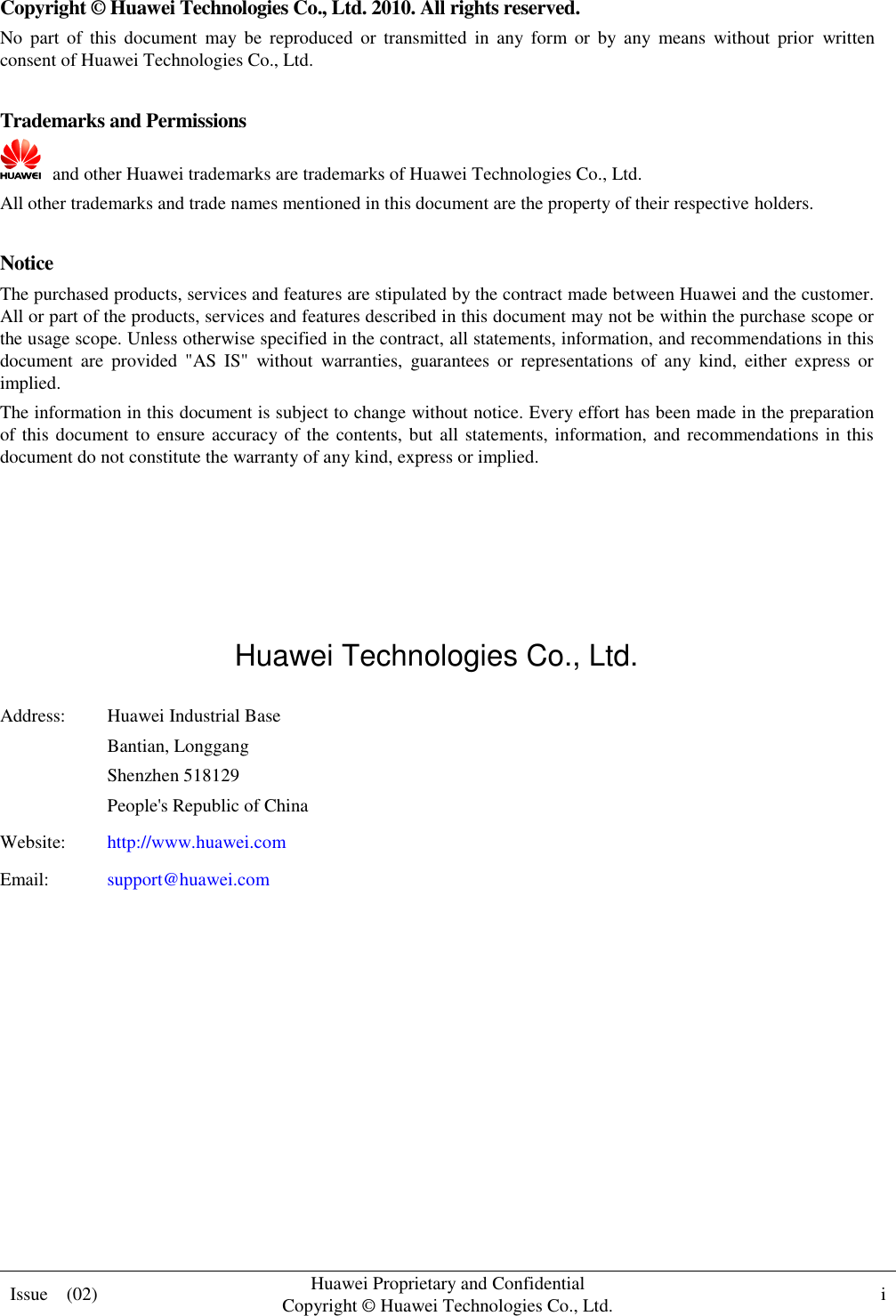
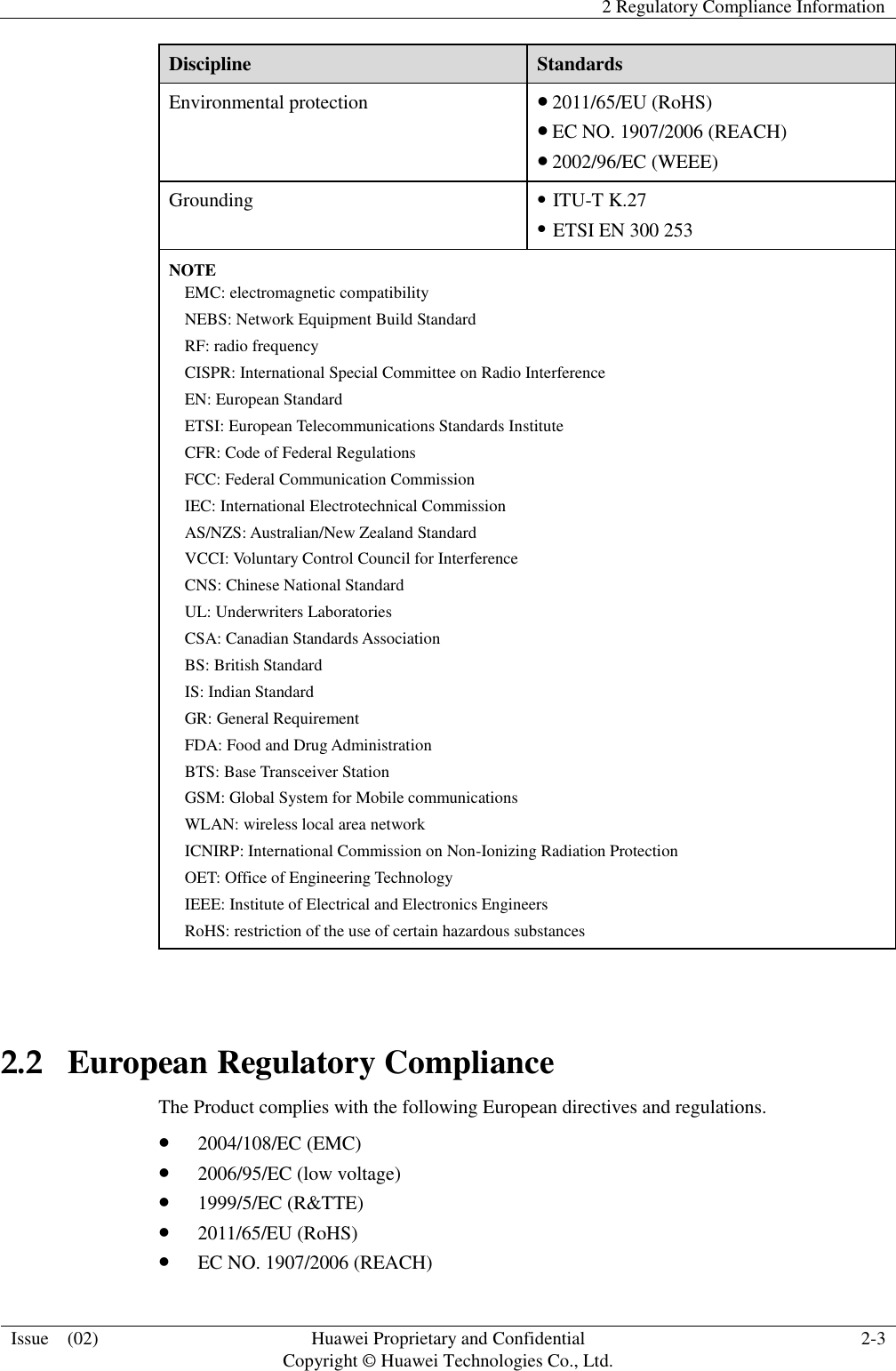
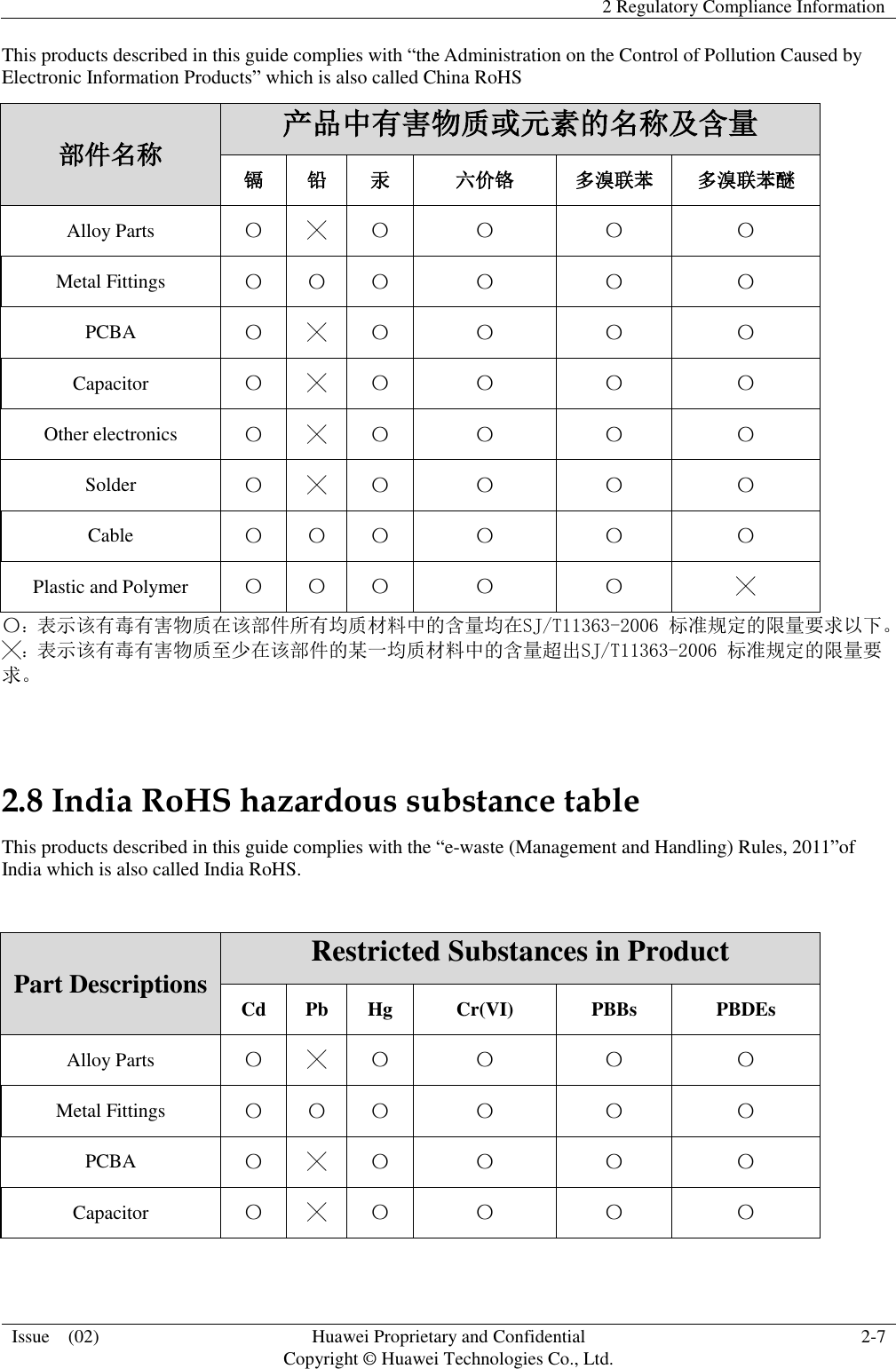
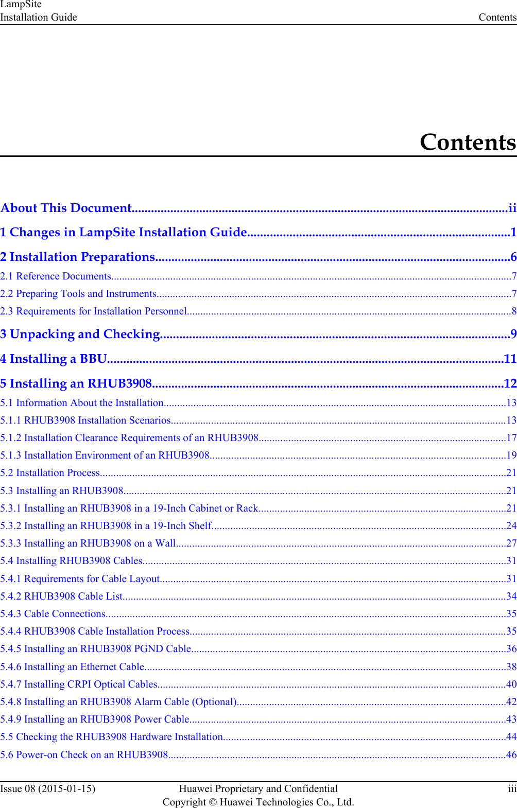
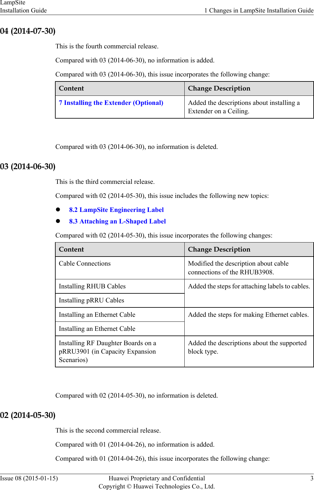
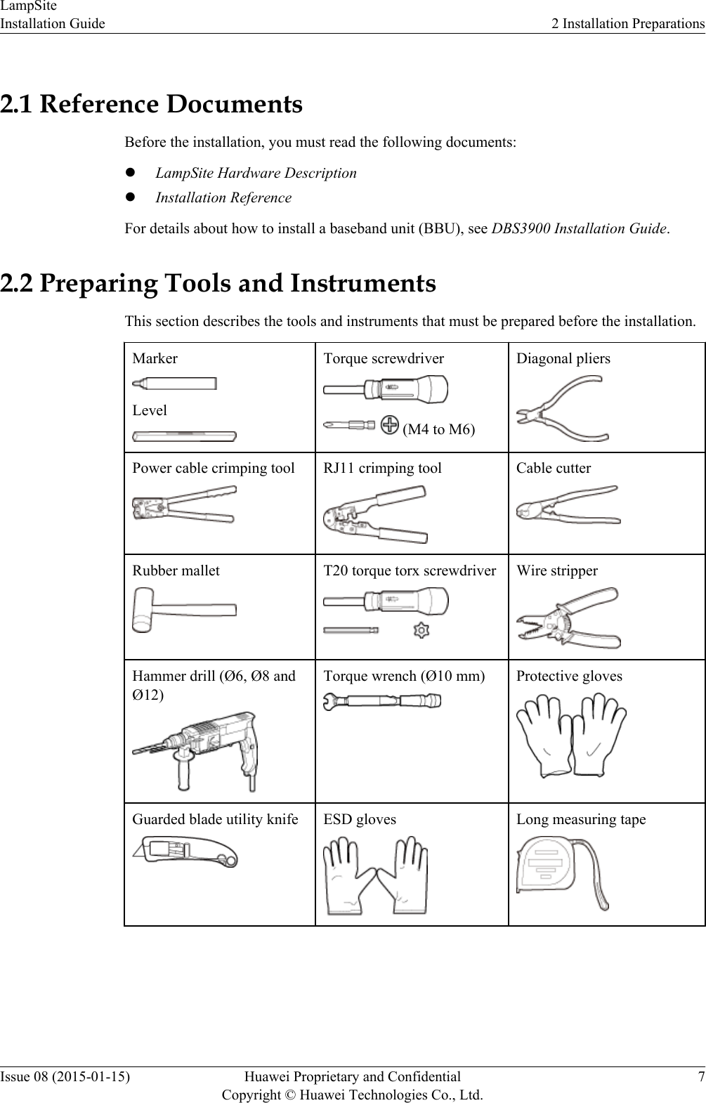
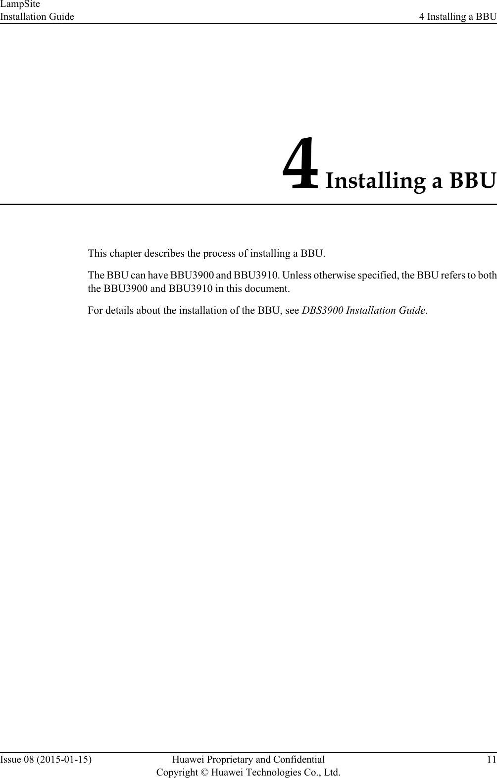
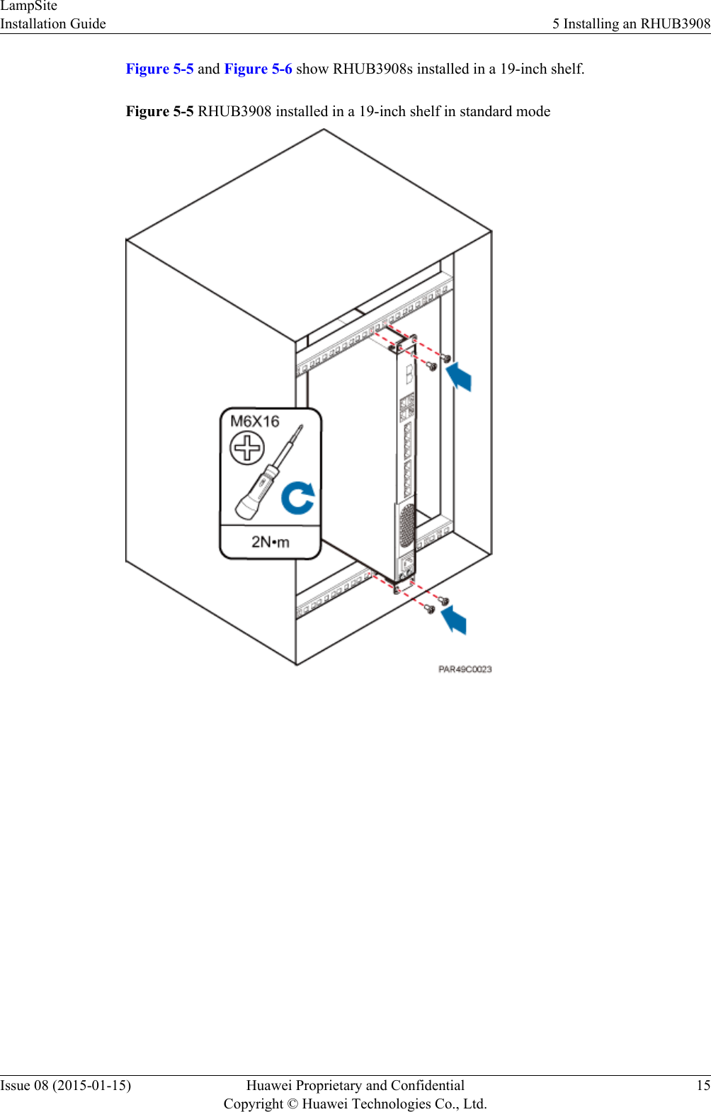
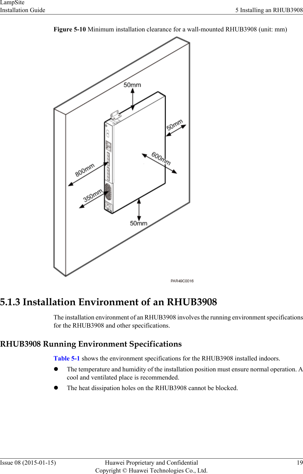
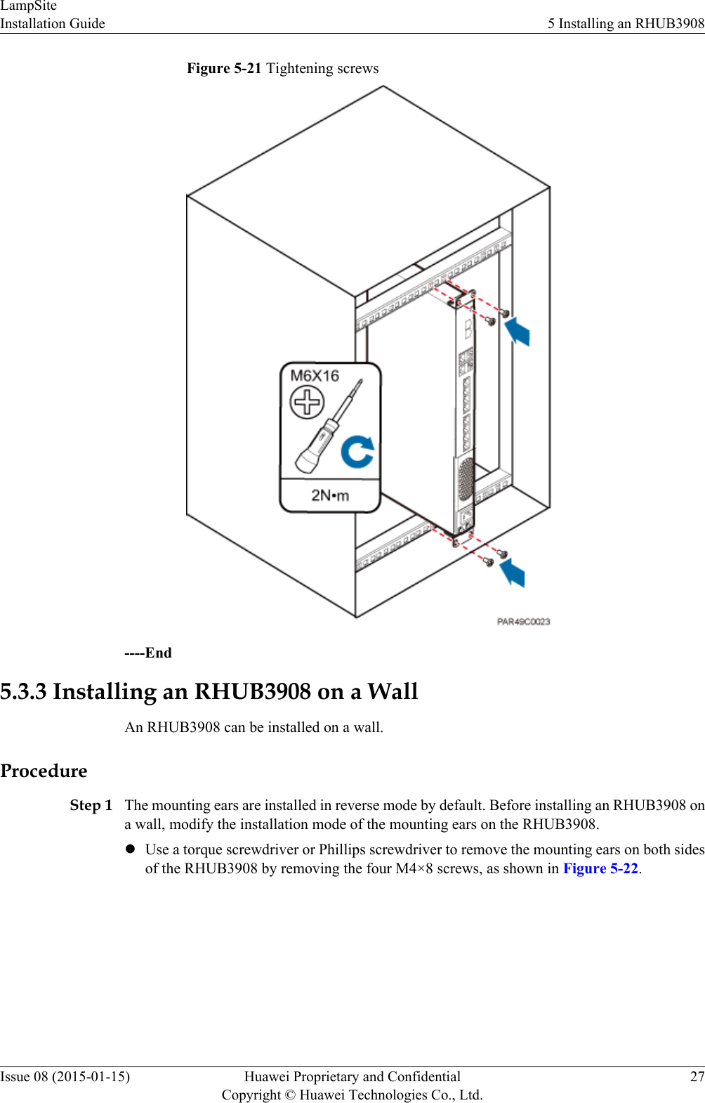
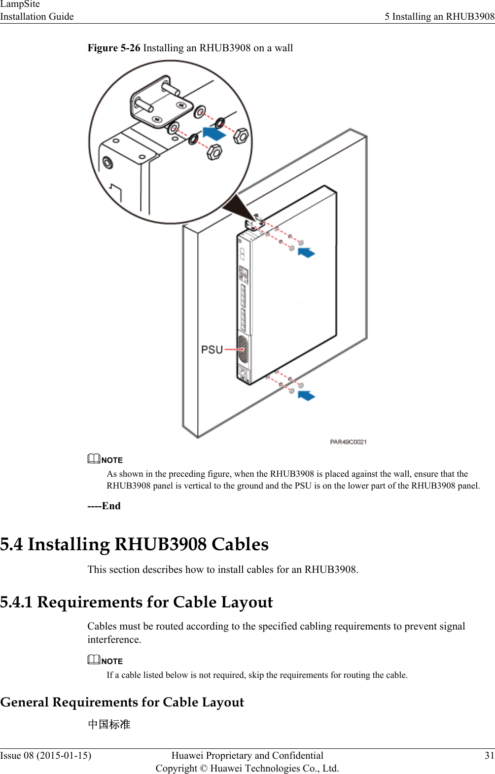
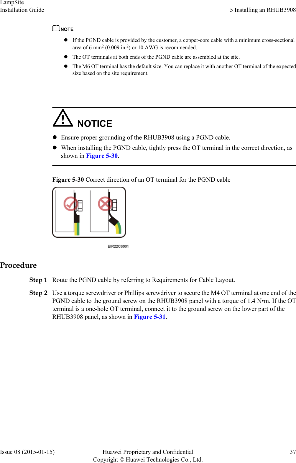
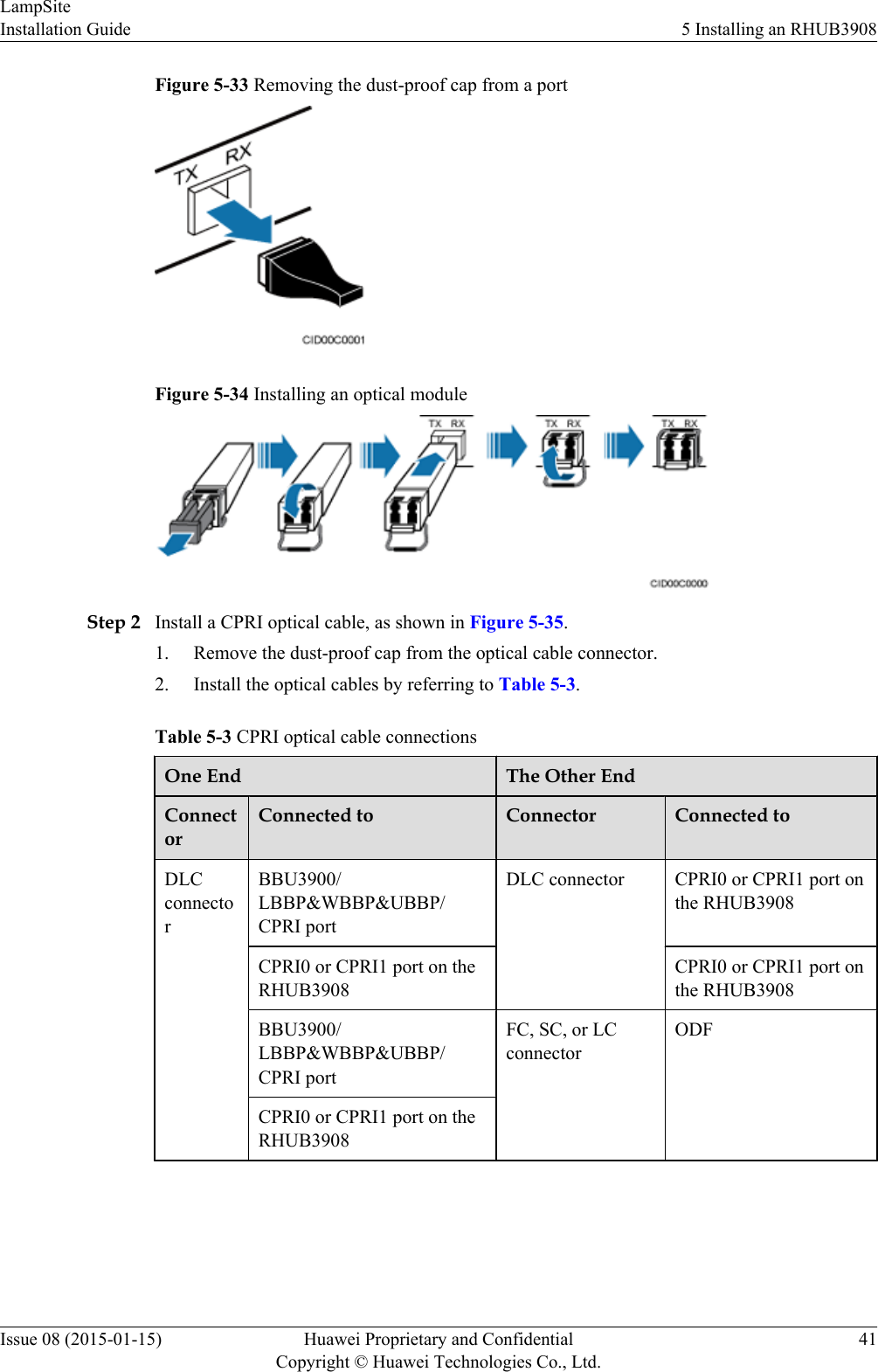
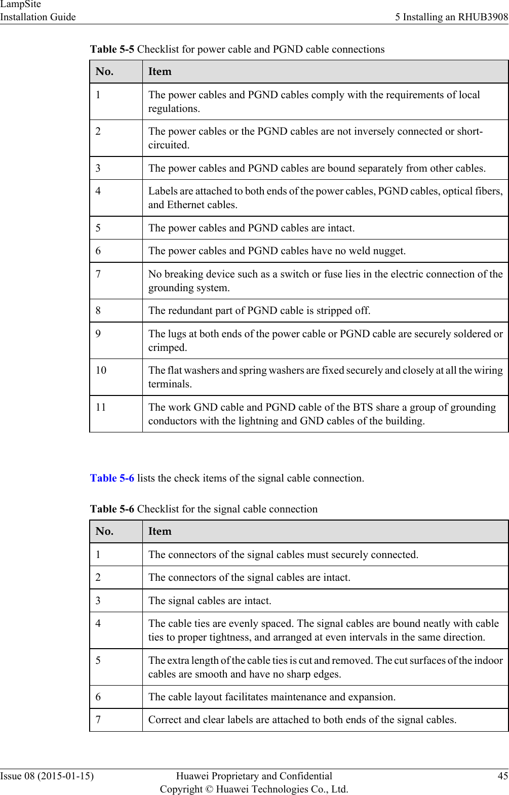
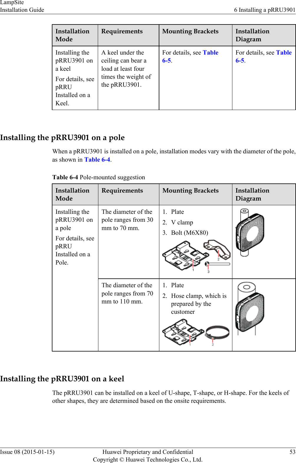
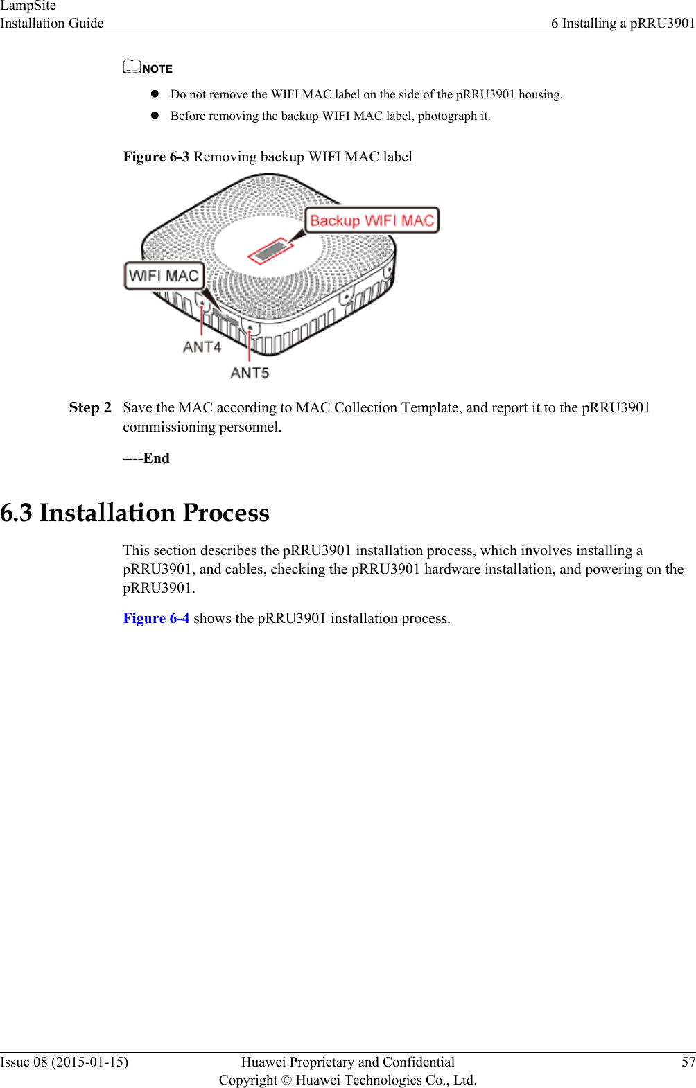
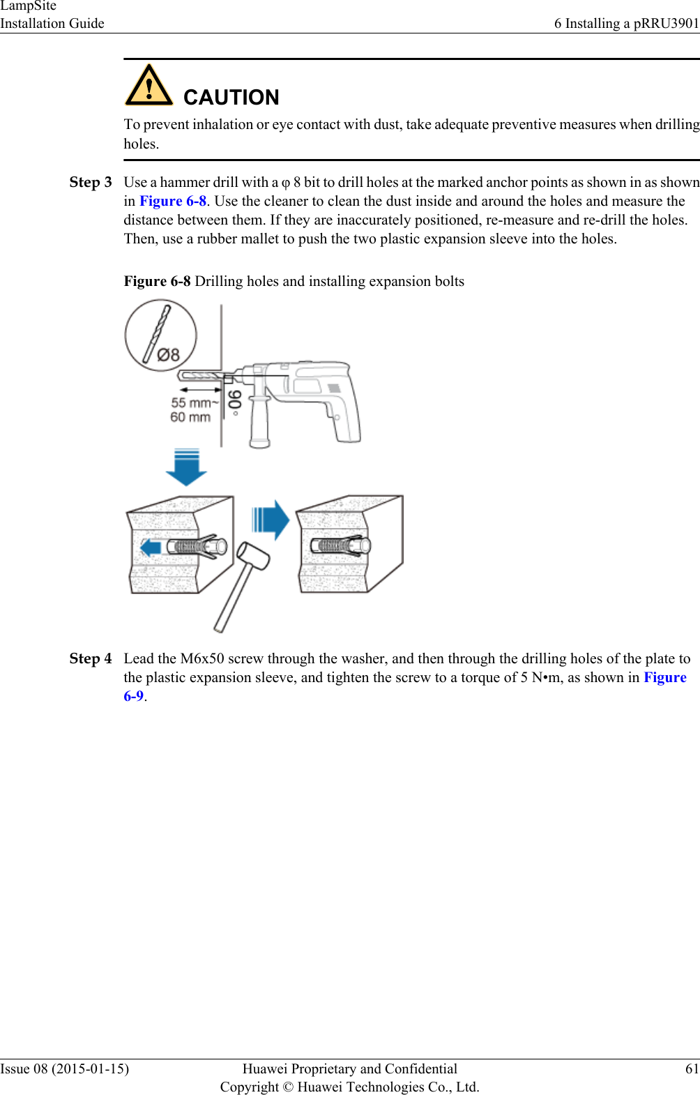
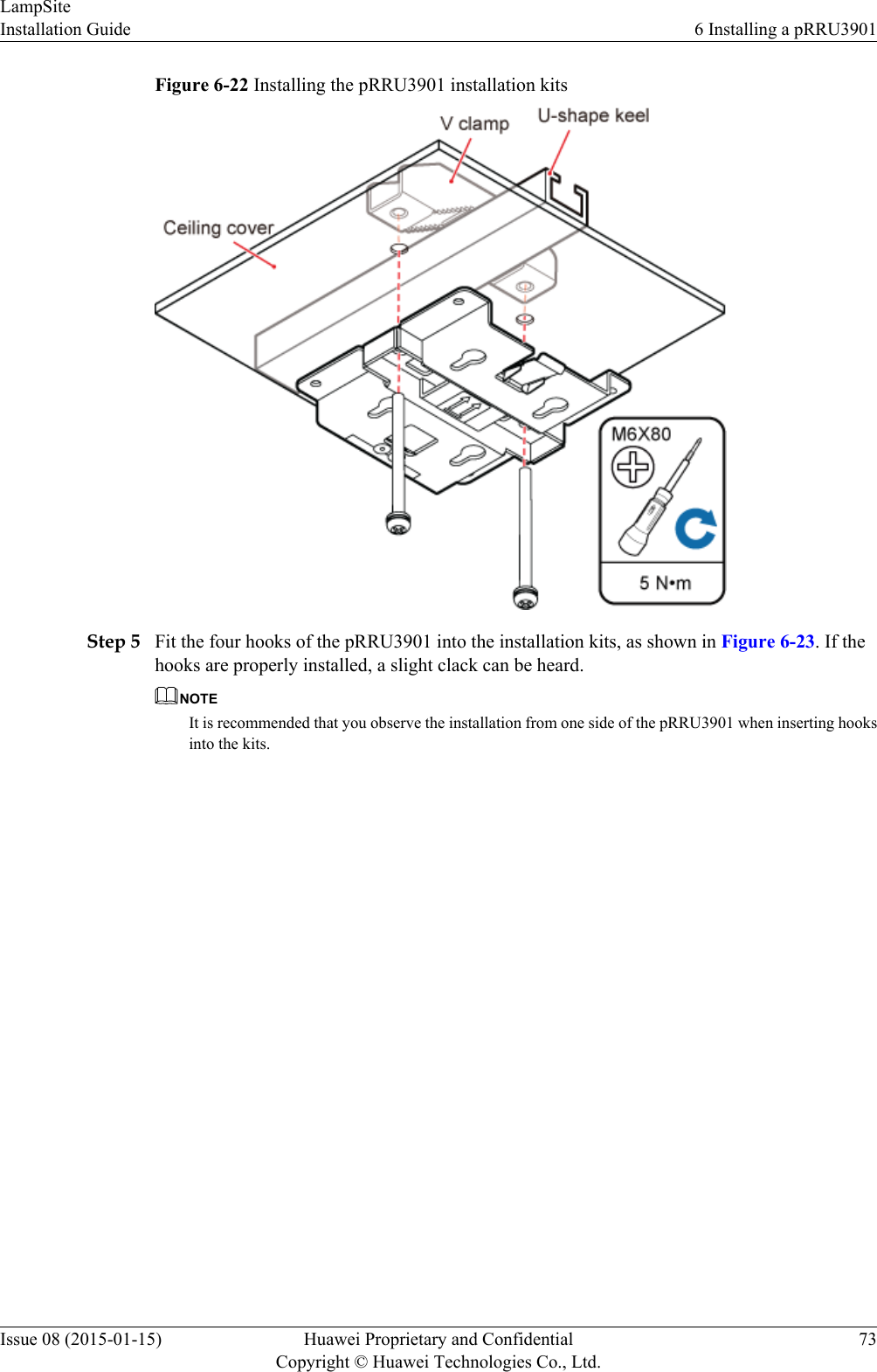
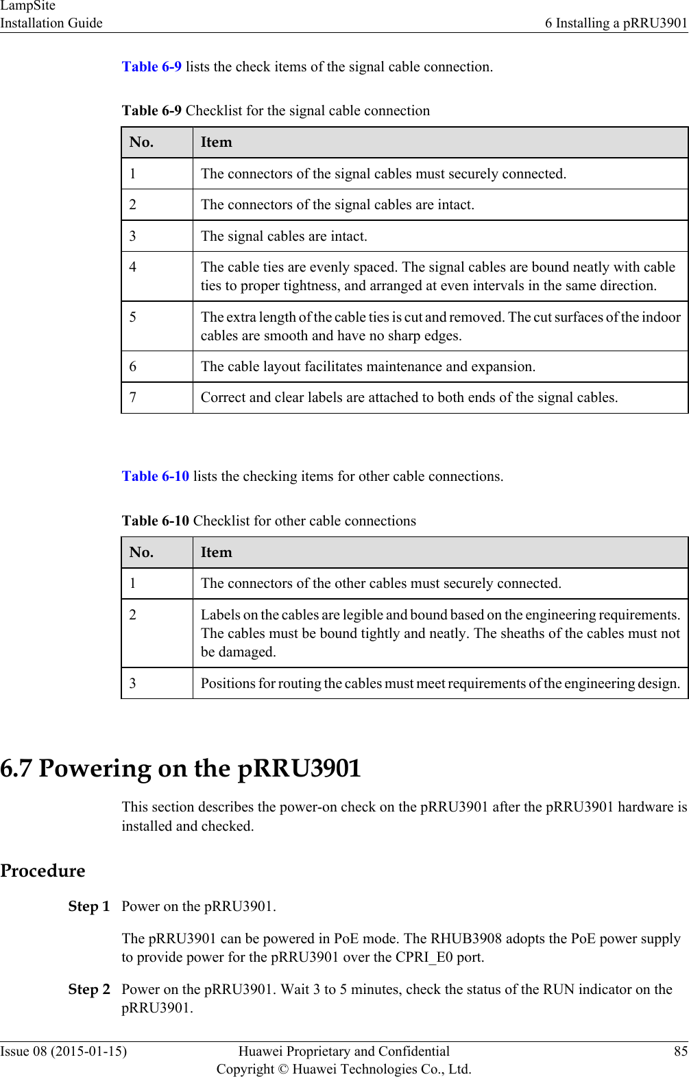
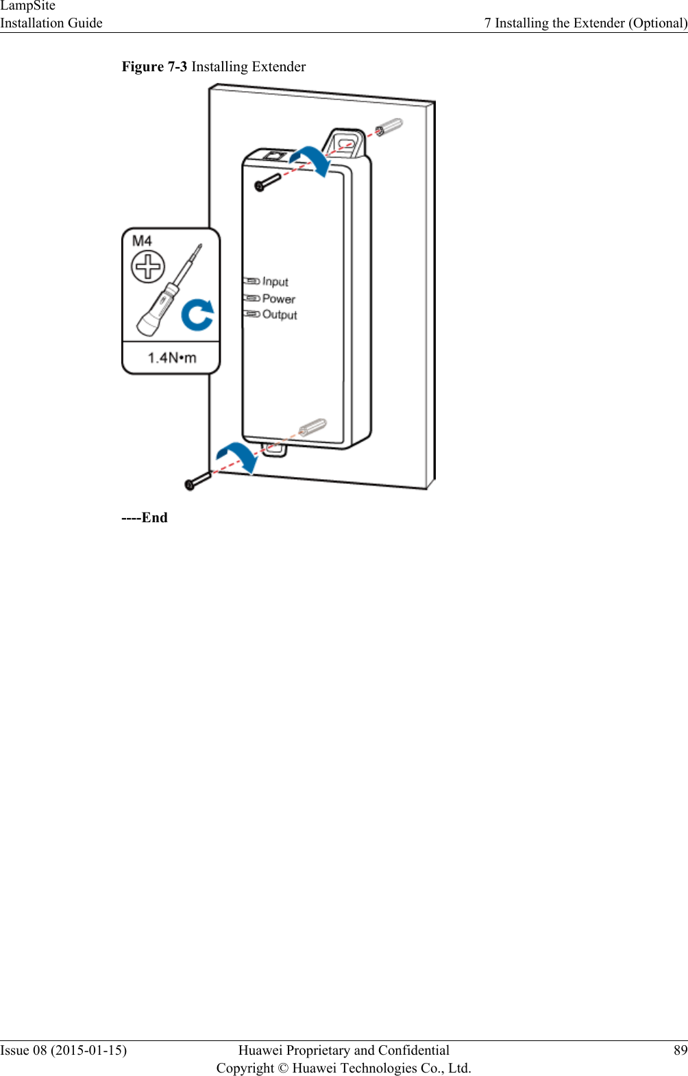
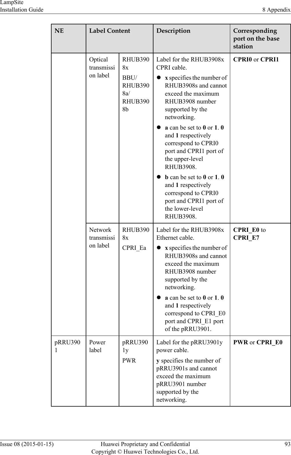
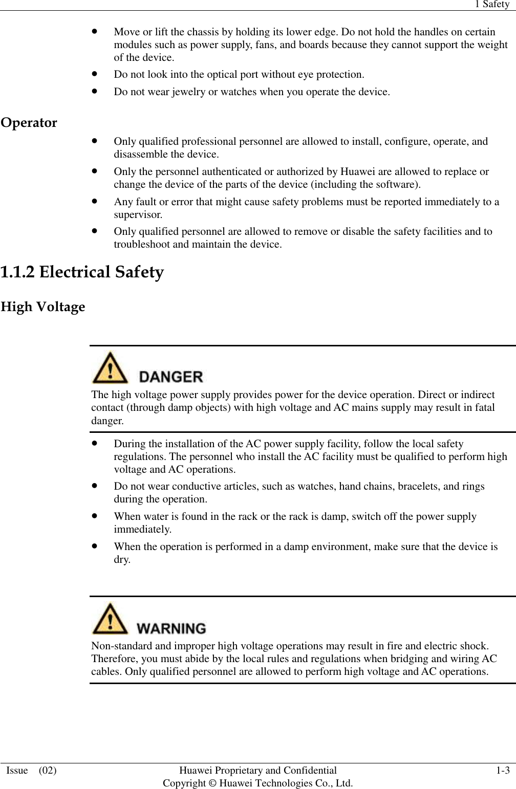
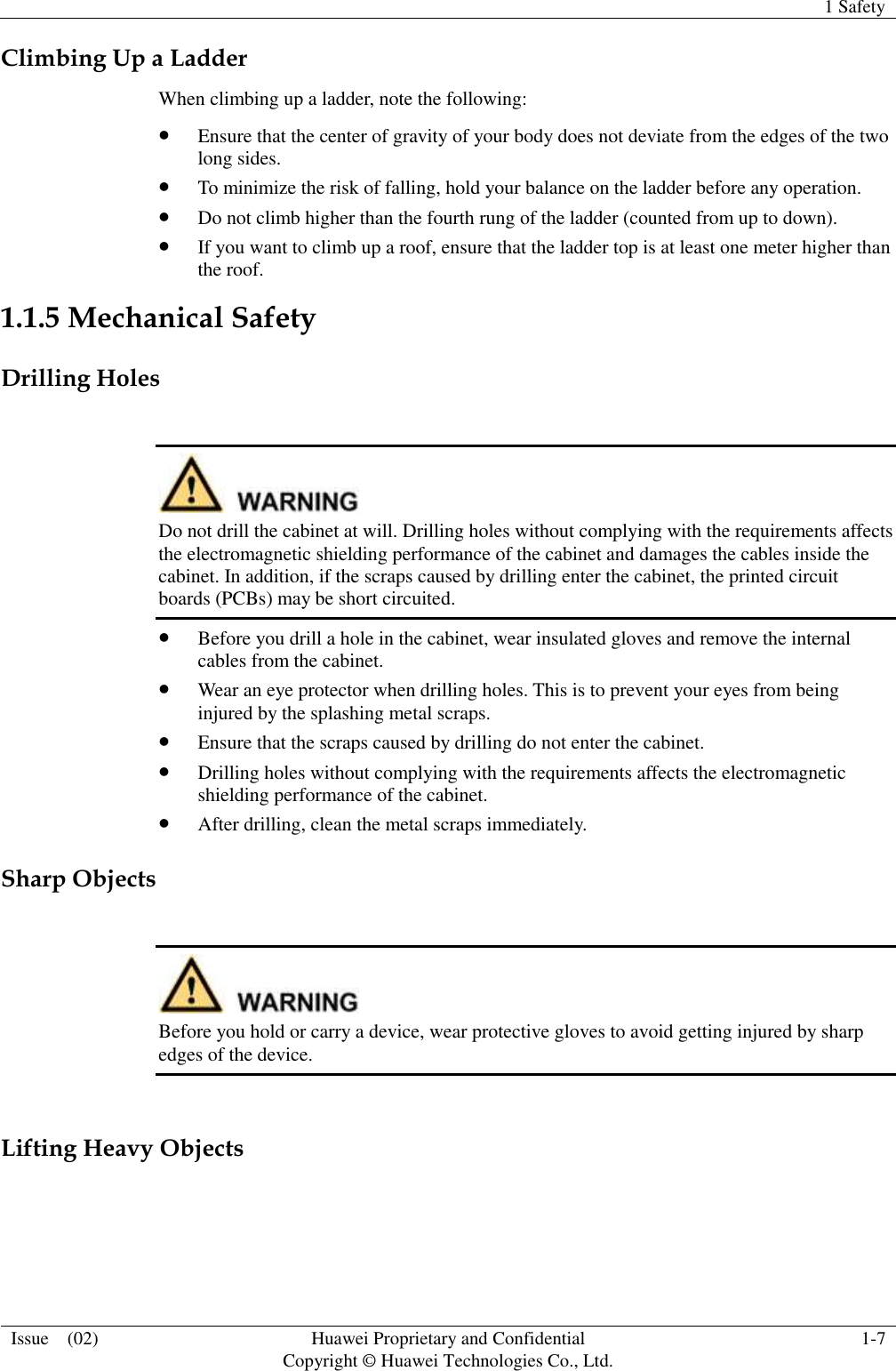
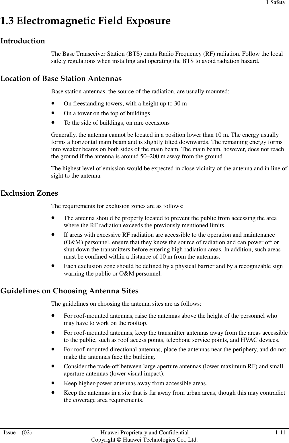
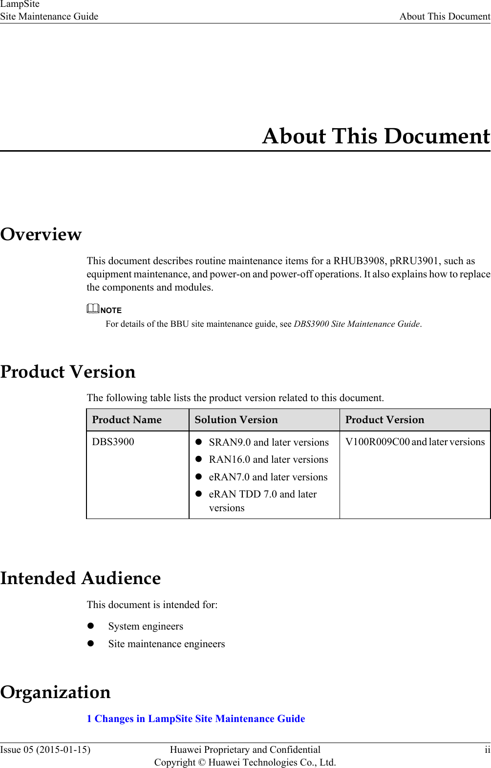
![Figure 5-28 RHUB3908 cable installation process5.4.5 Installing an RHUB3908 PGND CableAn RHUB3908 PGND cable ensures proper grounding of an RHUB3908.PrerequisitesThe OT terminals at both ends of the PGND cable are prepared.ContextThe yellow and green or green PGND cable is a single cable. The cross-sectional area of thePGND cable is 6 mm2 (0.009 in.2). Both ends of the cable are OT terminals, as shown in Figure1.Figure 5-29 Exterior of a PGND cable(1) OT terminal (6 mm2 [0.009 in.2], M4) (2) OT terminal (6 mm2 [0.009 in.2], M6)LampSiteInstallation Guide 5 Installing an RHUB3908Issue 08 (2015-01-15) Huawei Proprietary and ConfidentialCopyright © Huawei Technologies Co., Ltd.36](https://usermanual.wiki/Huawei-Technologies/PRU01P2G6/User-Guide-2703608-Page-41.png)
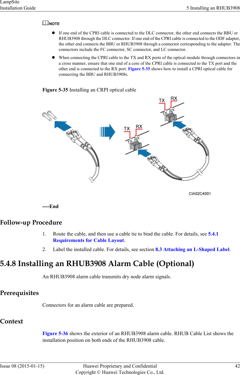
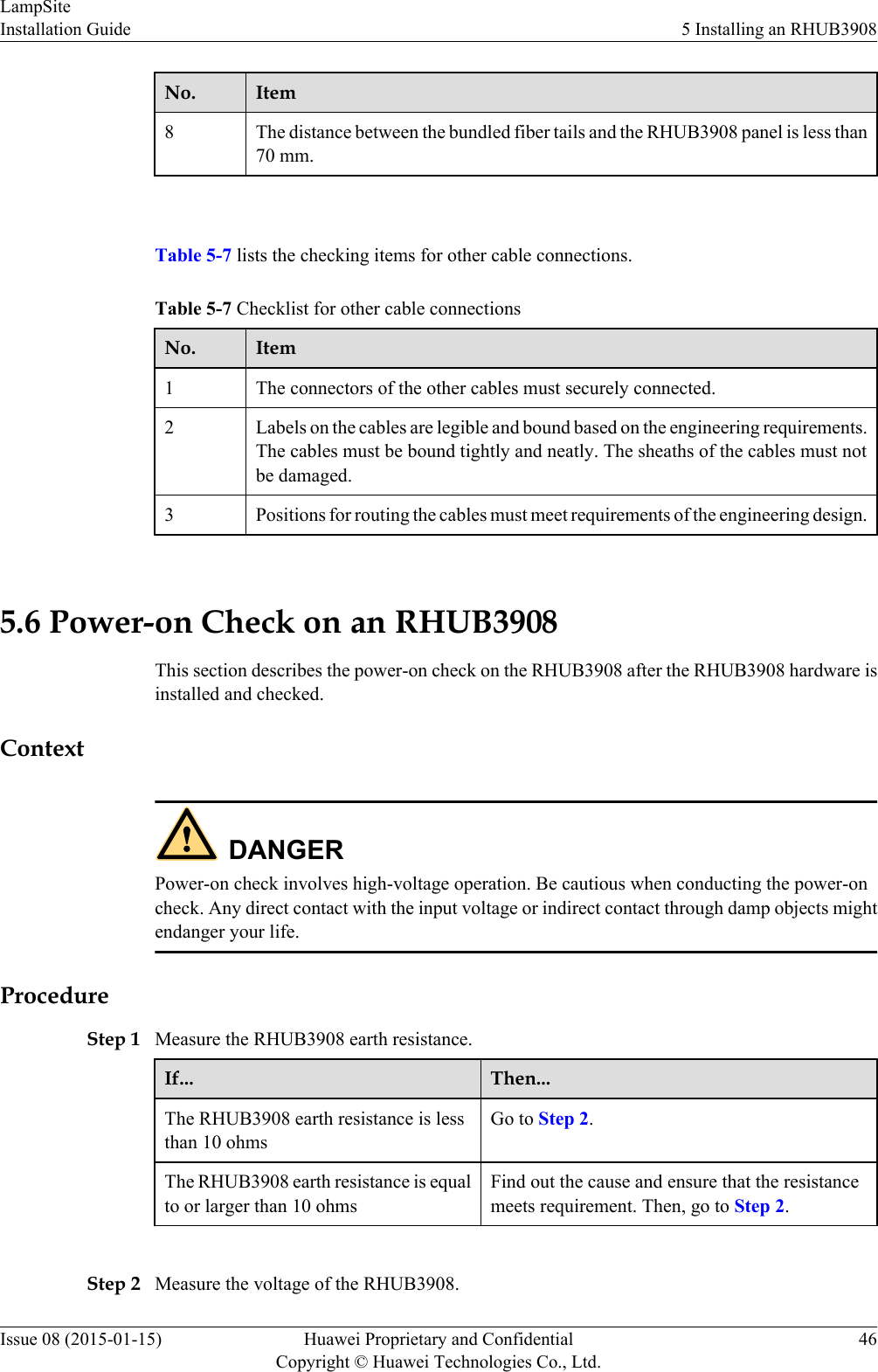
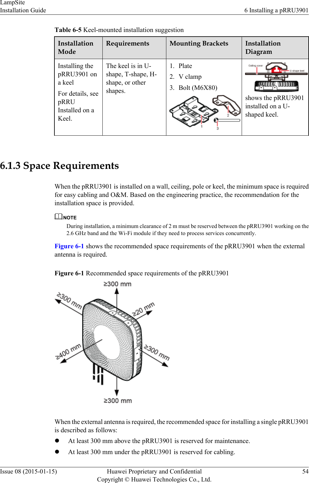
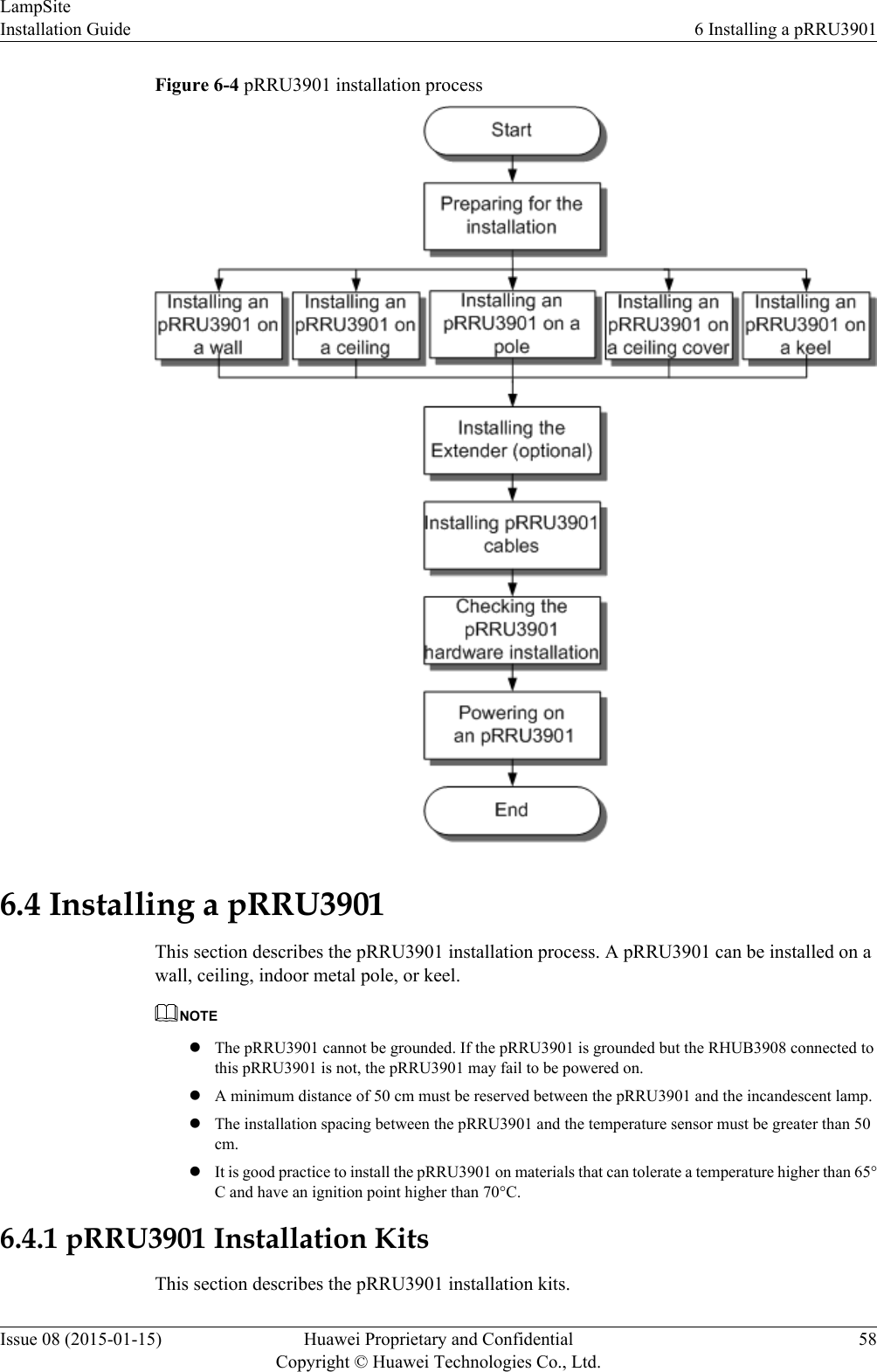
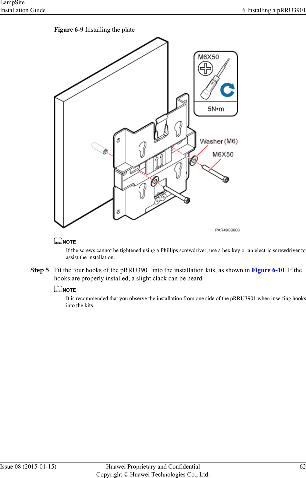
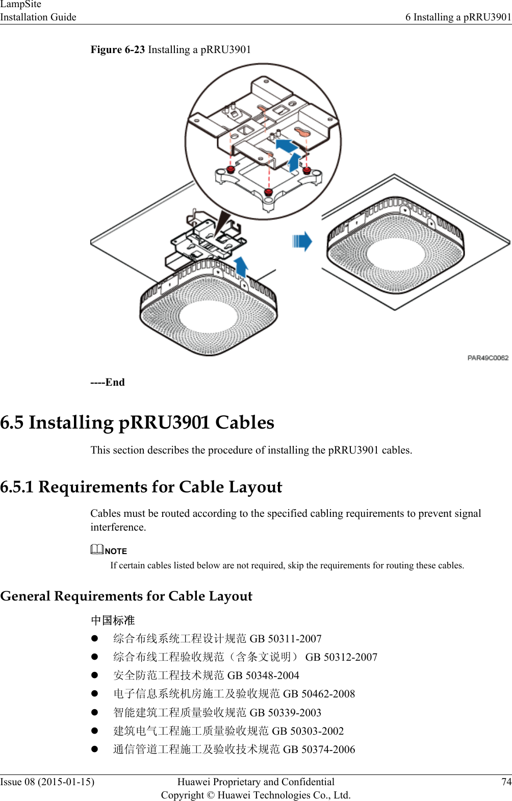
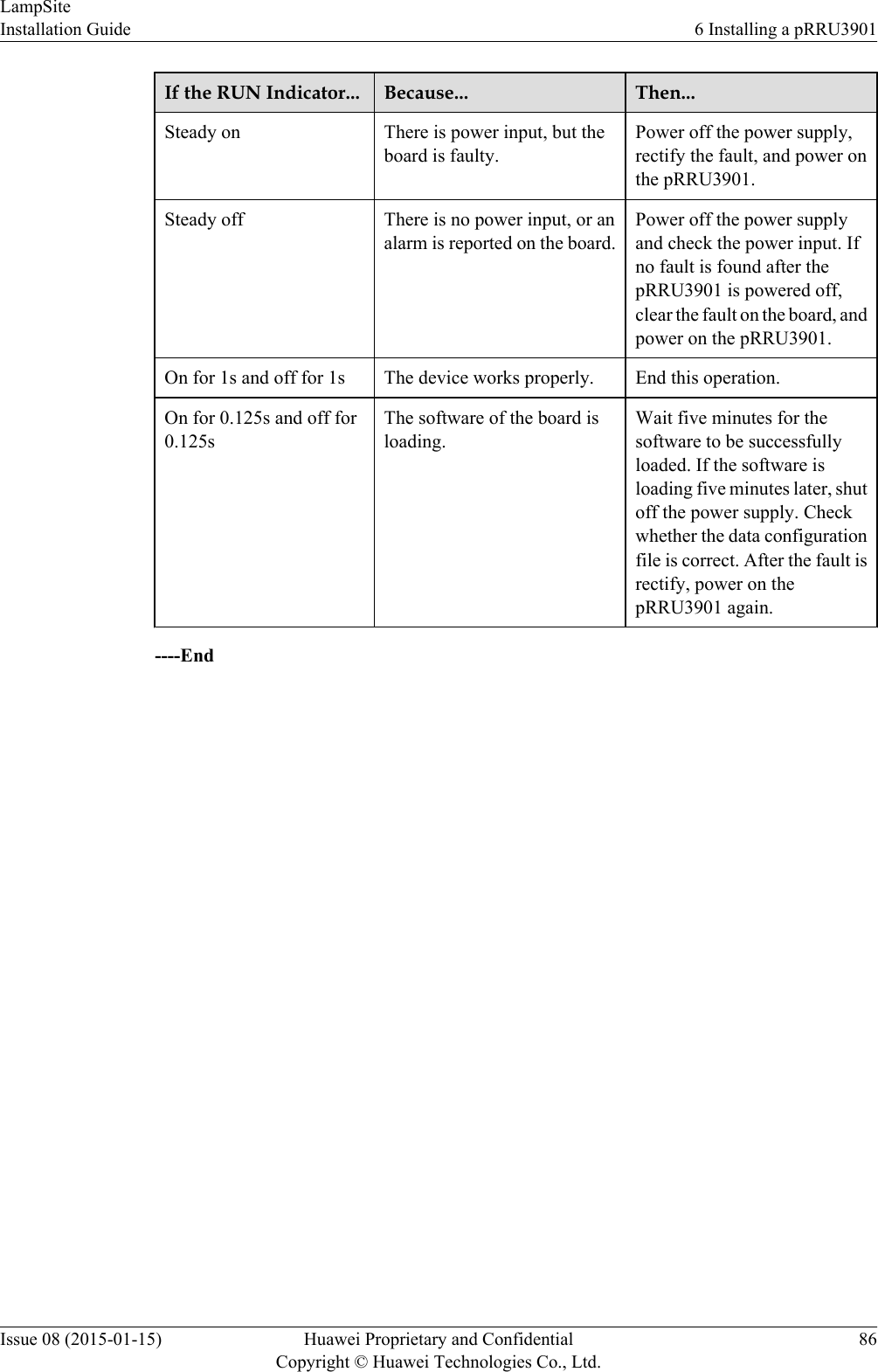
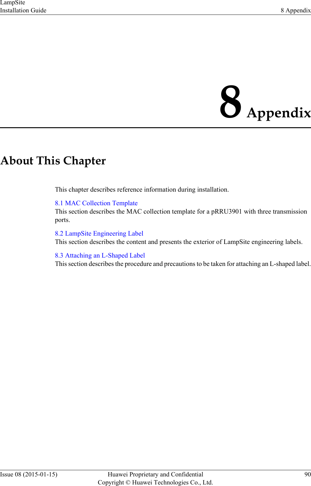
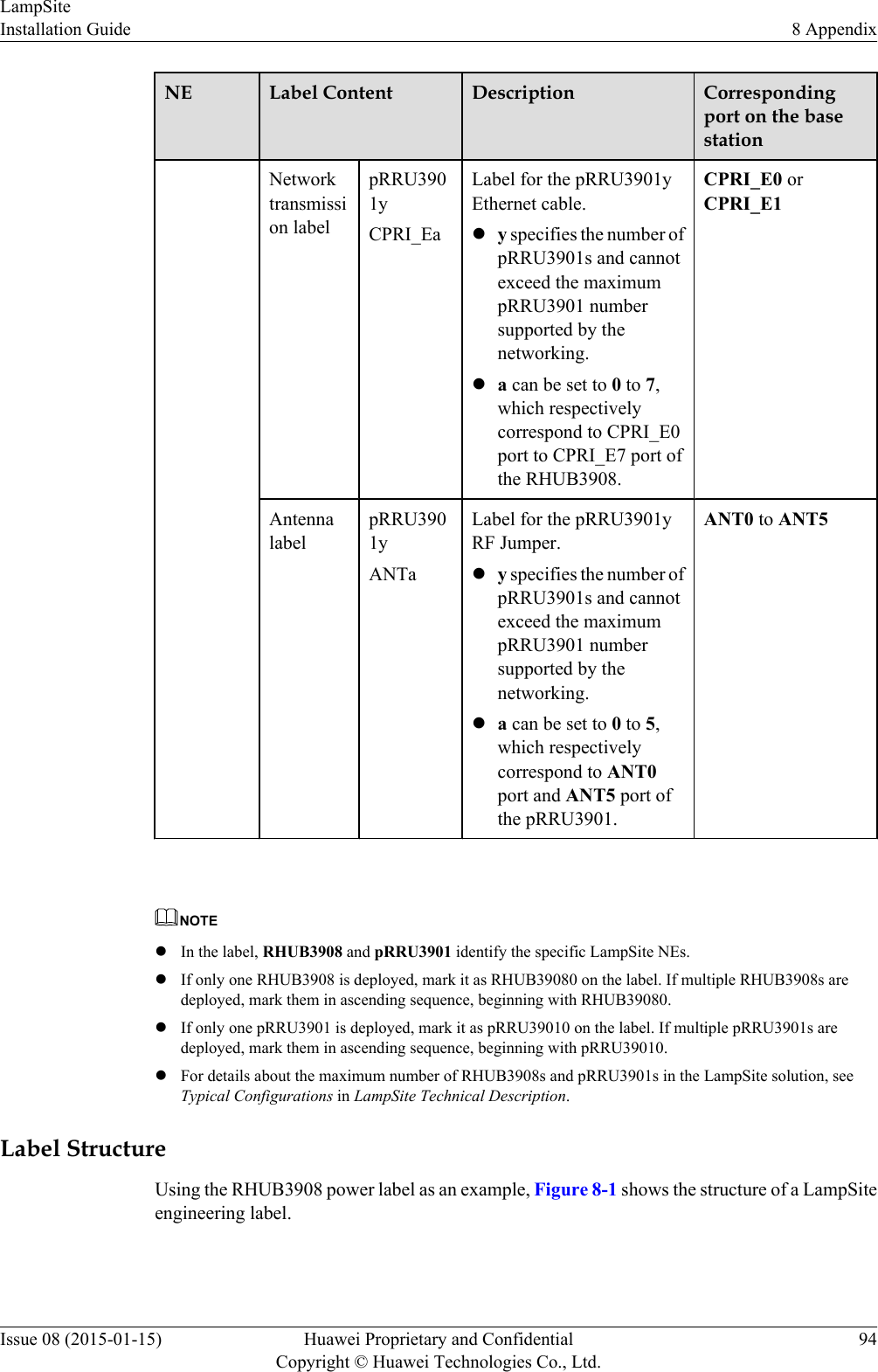
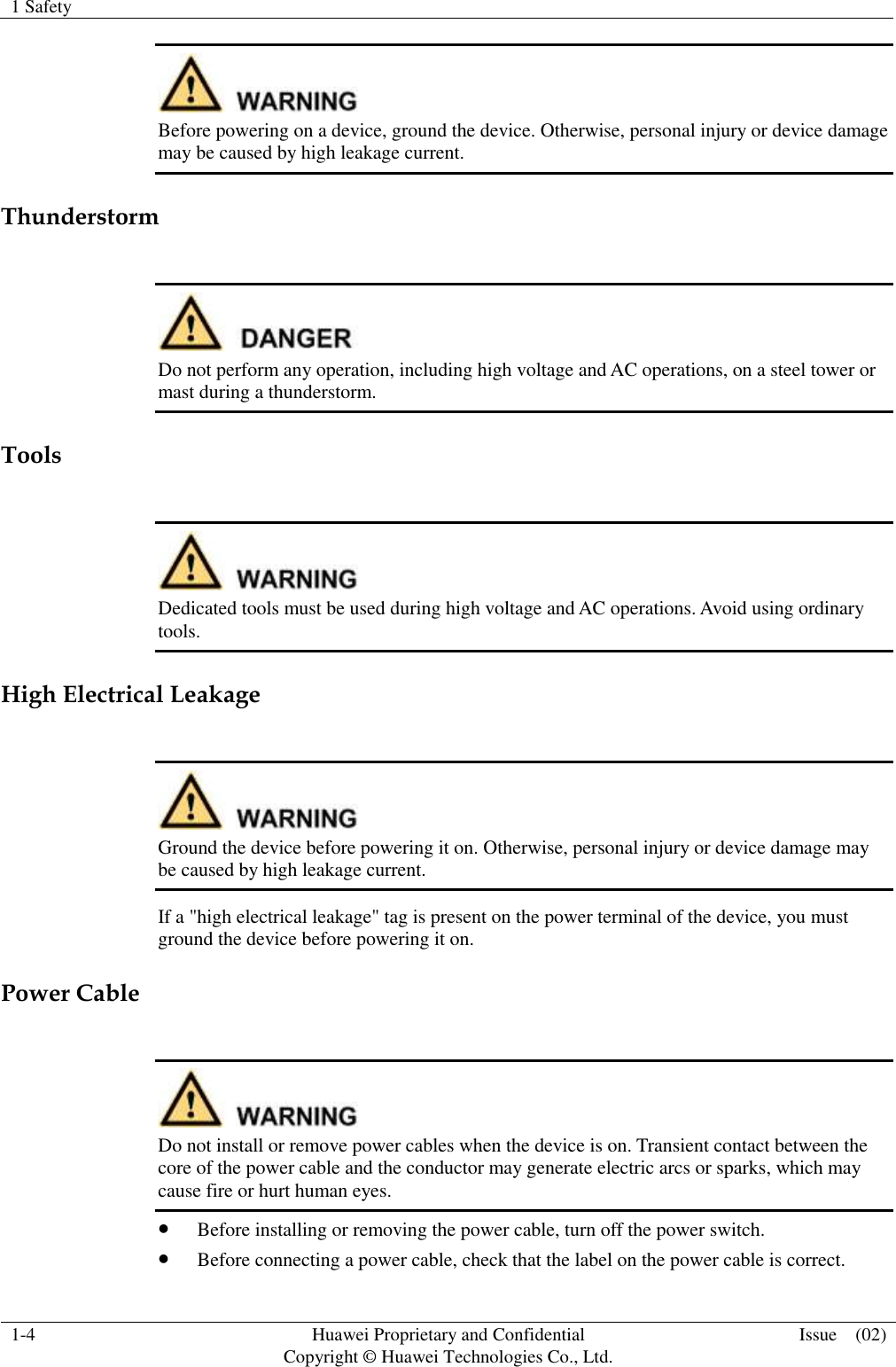
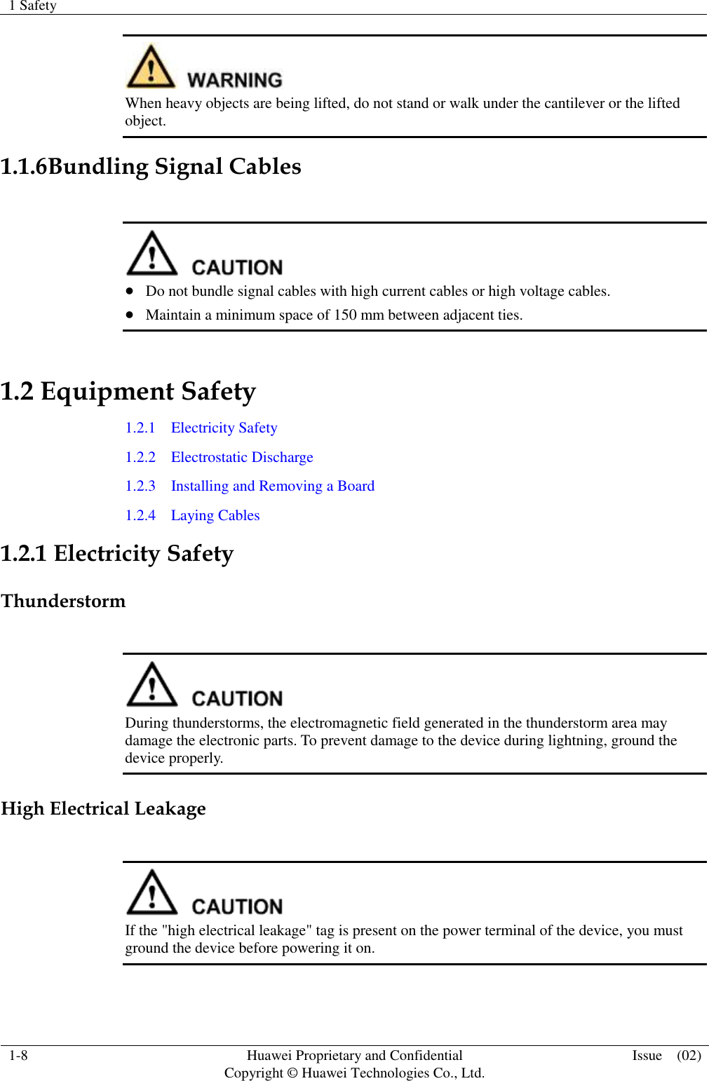
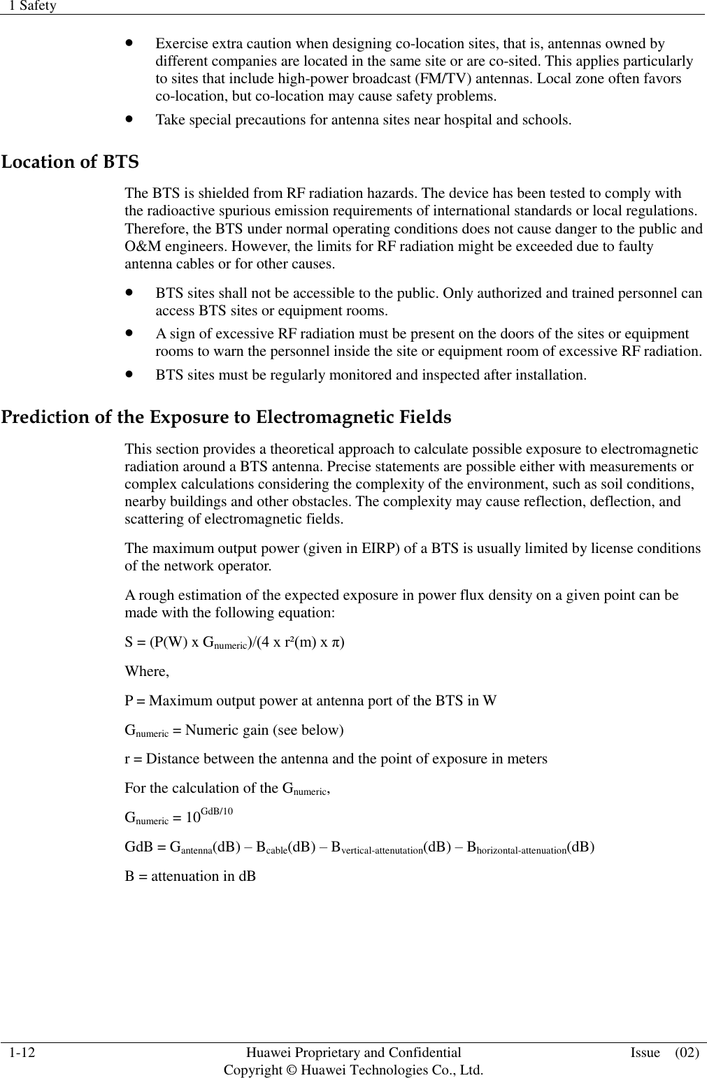
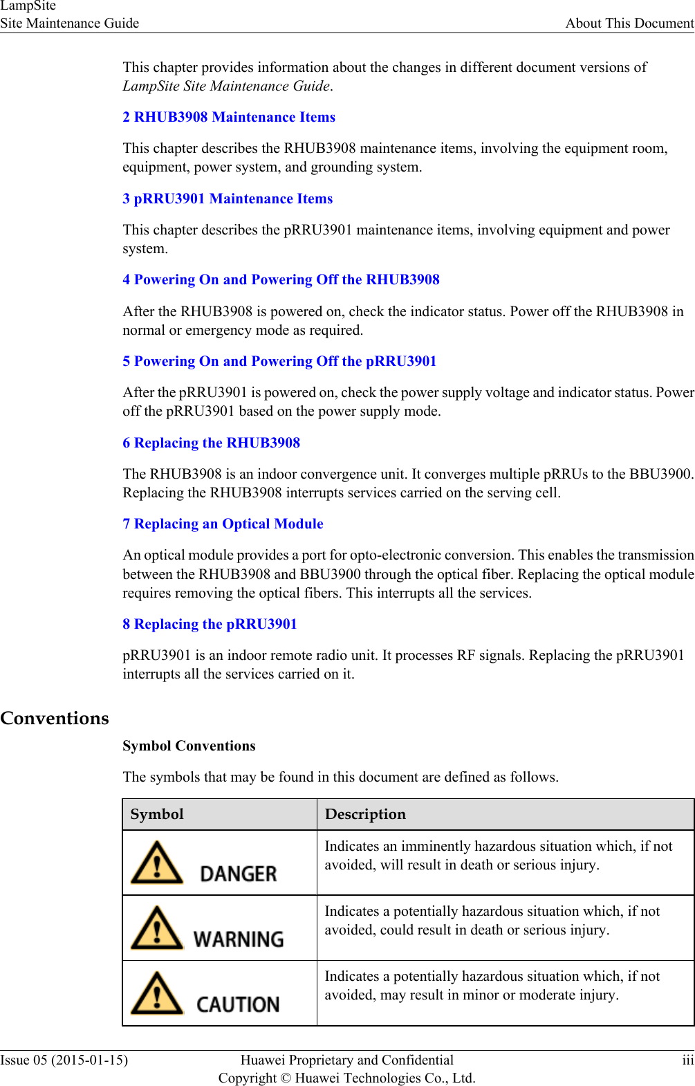
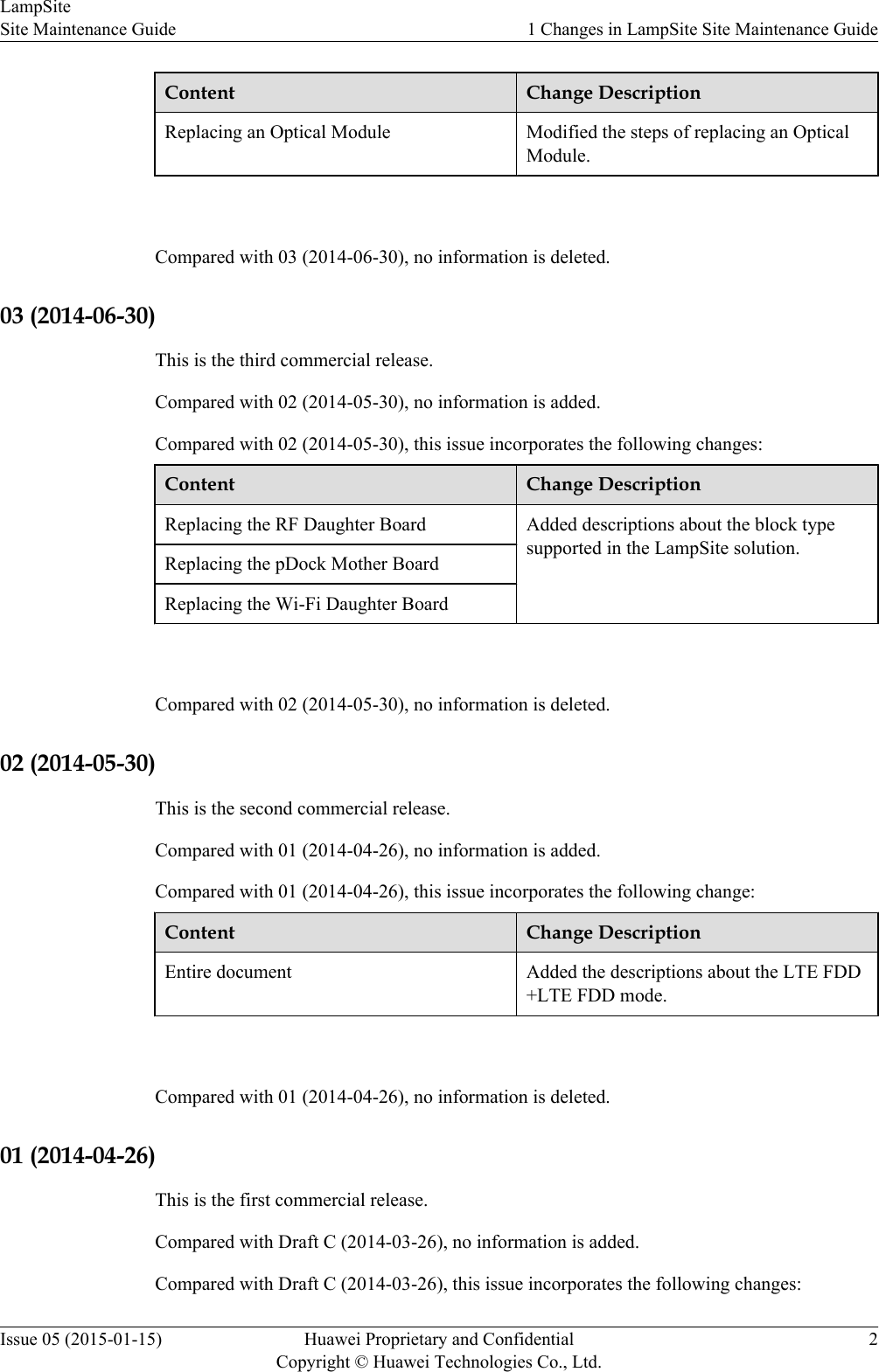
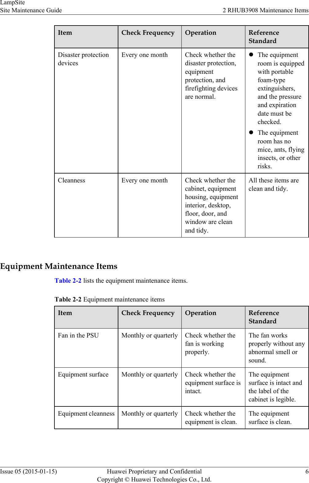
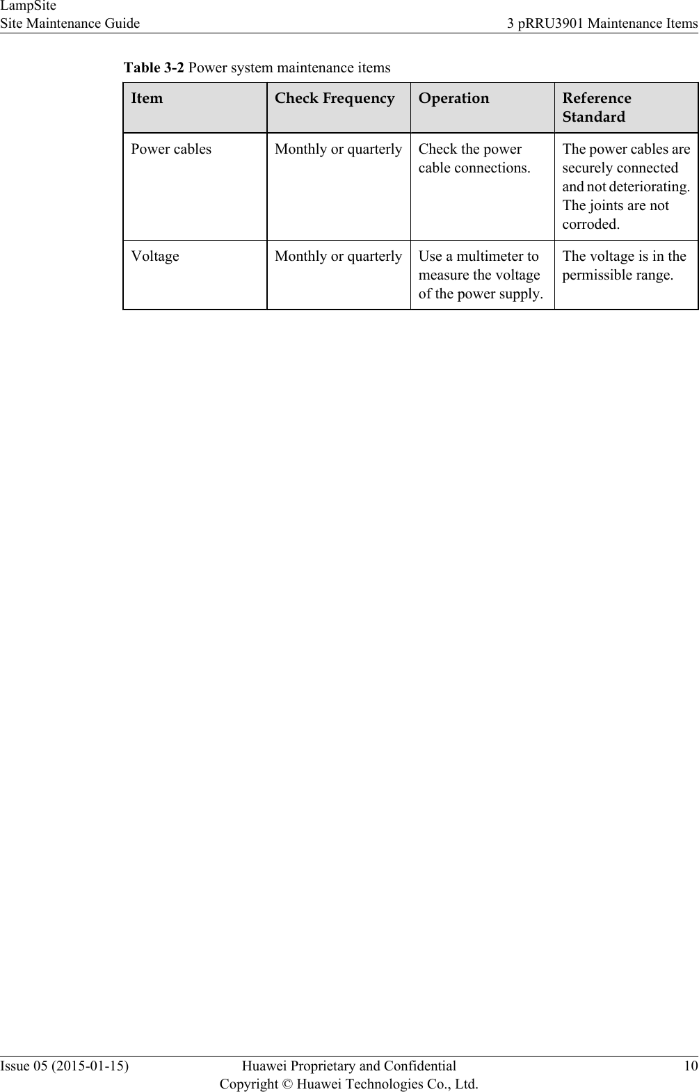
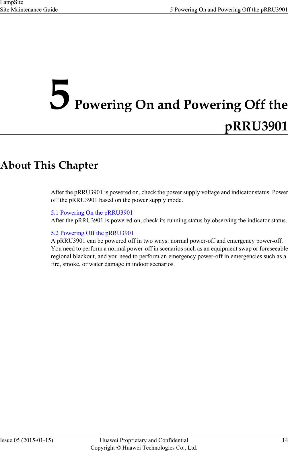
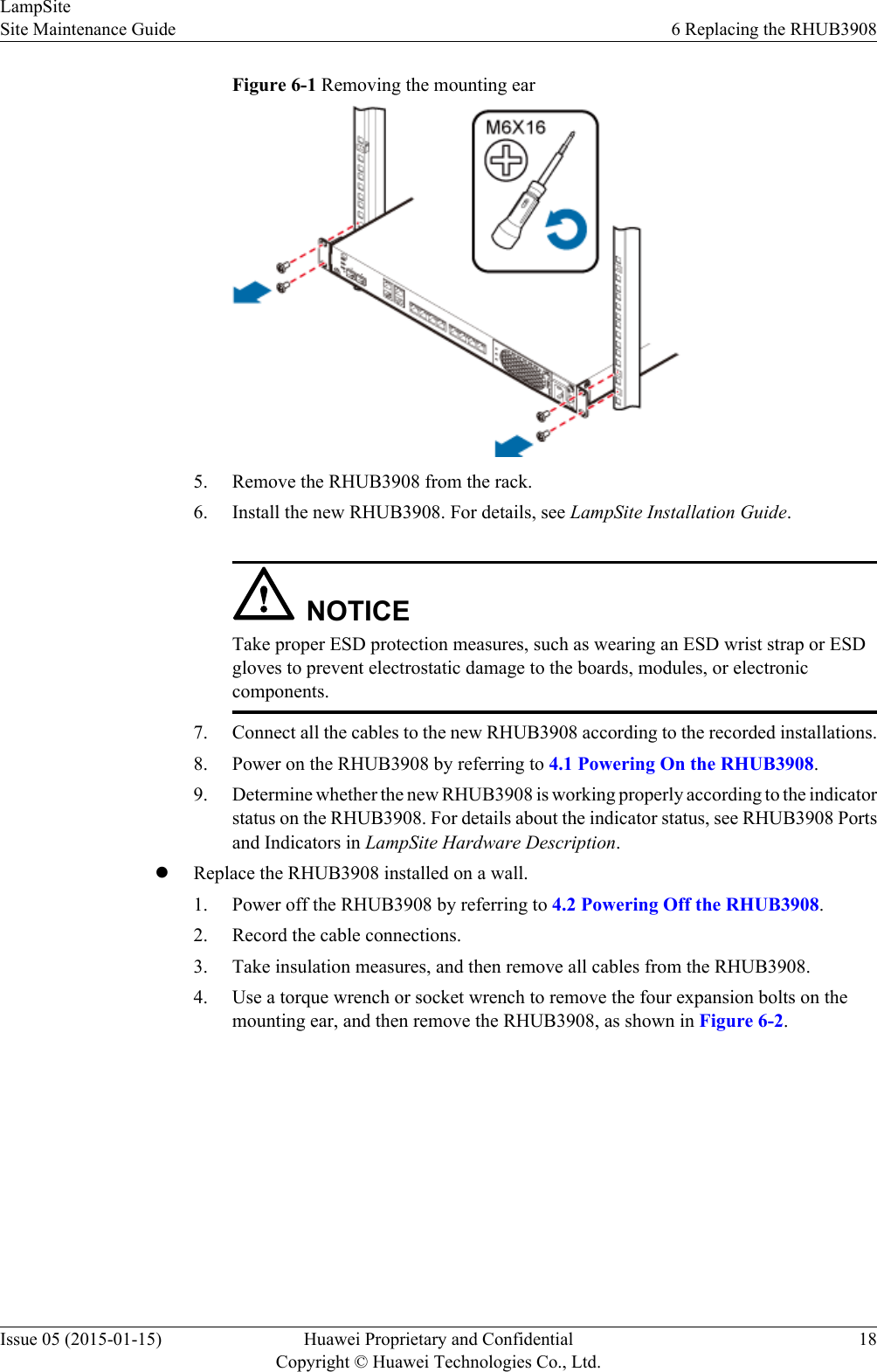
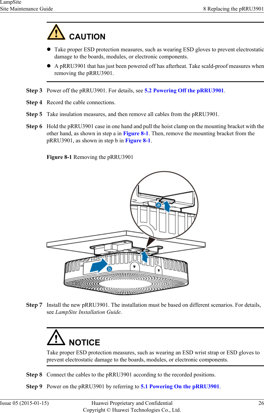
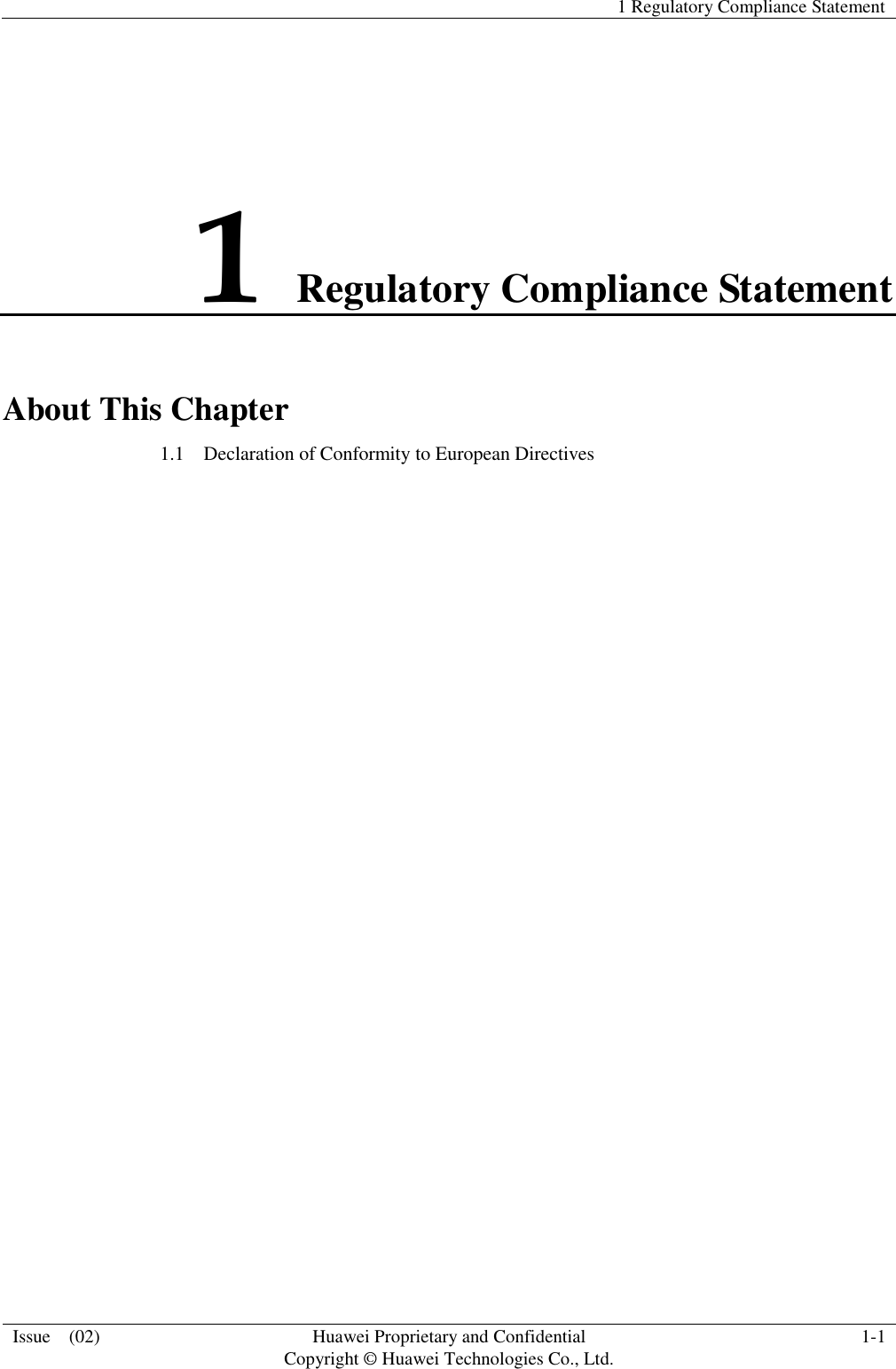
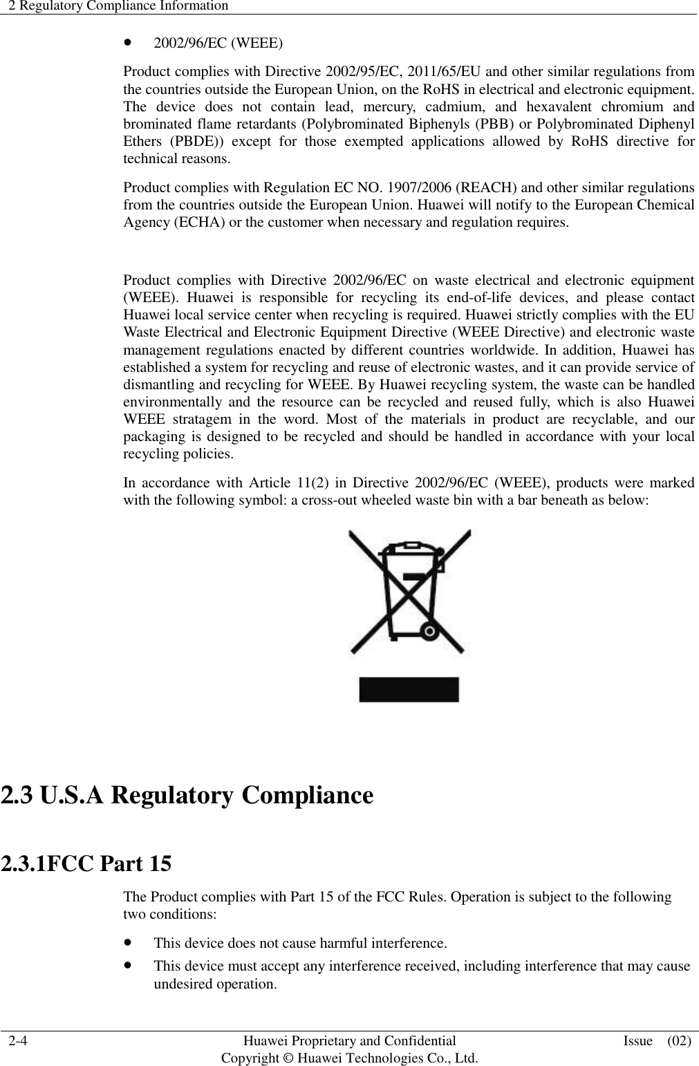
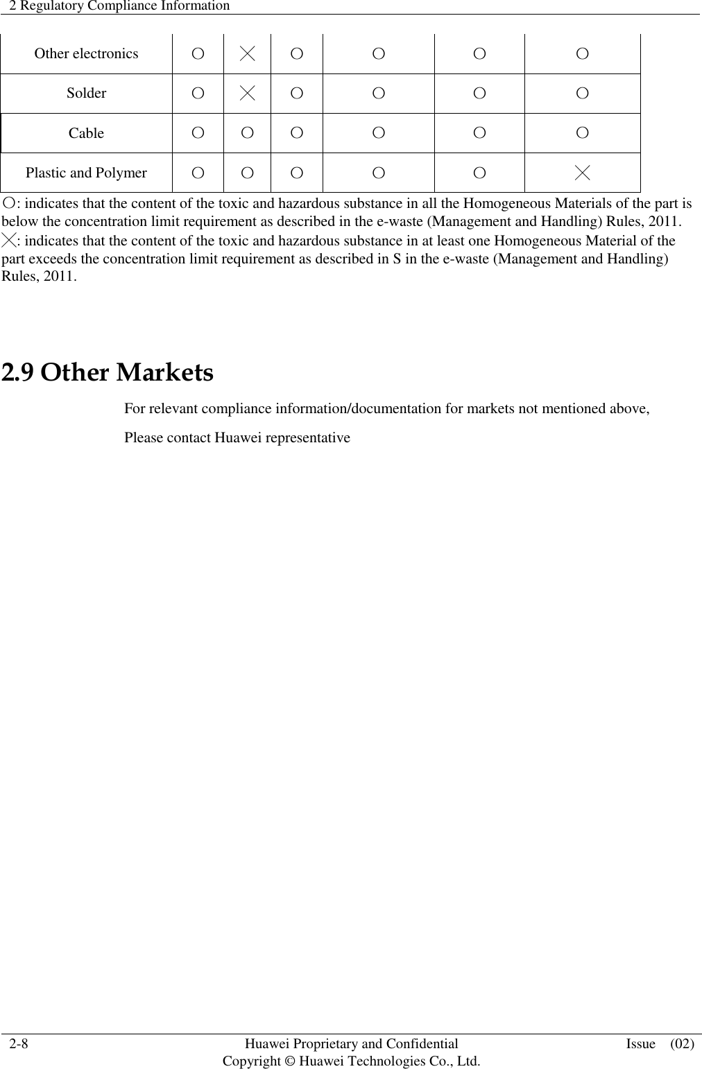
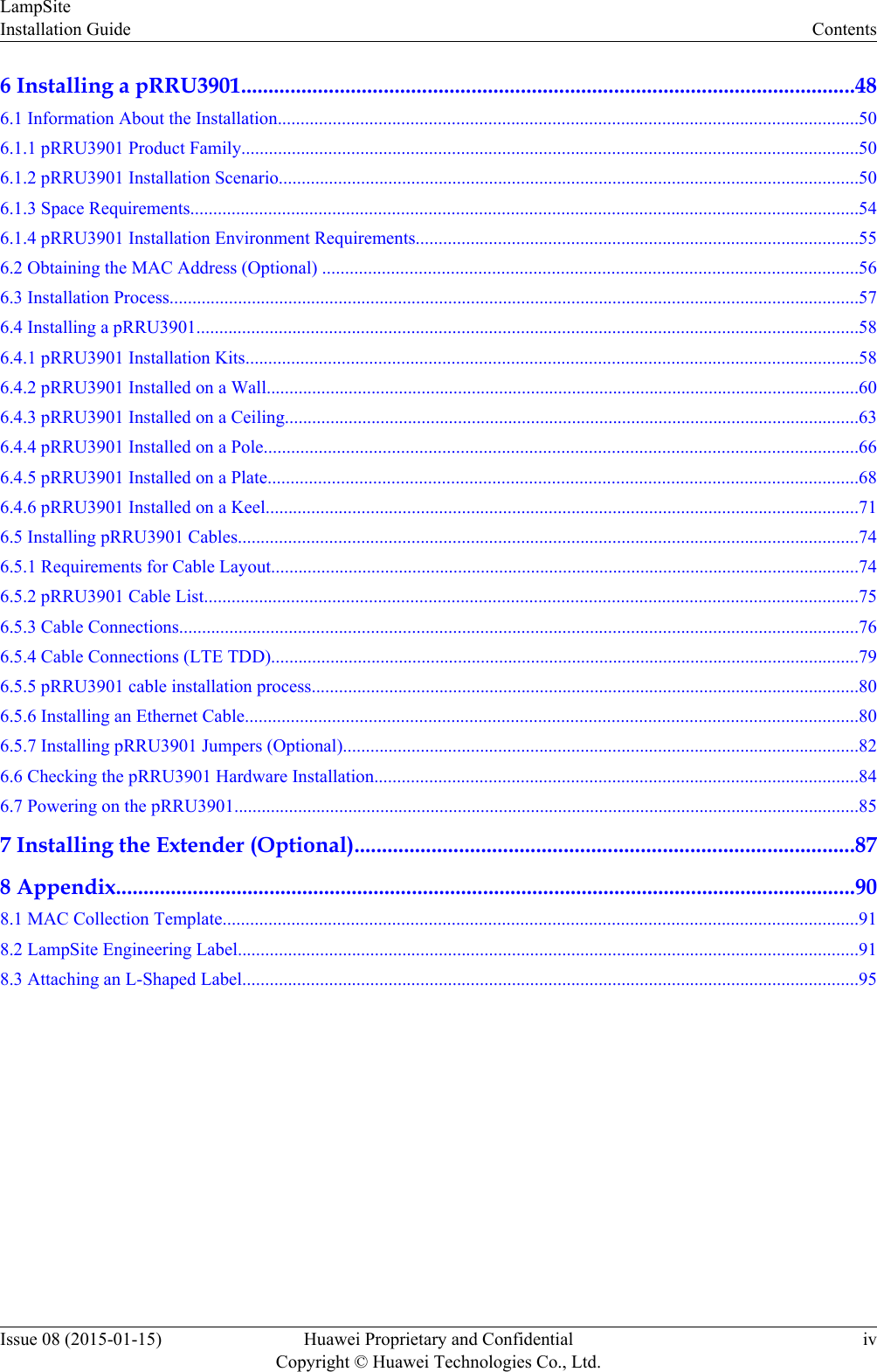
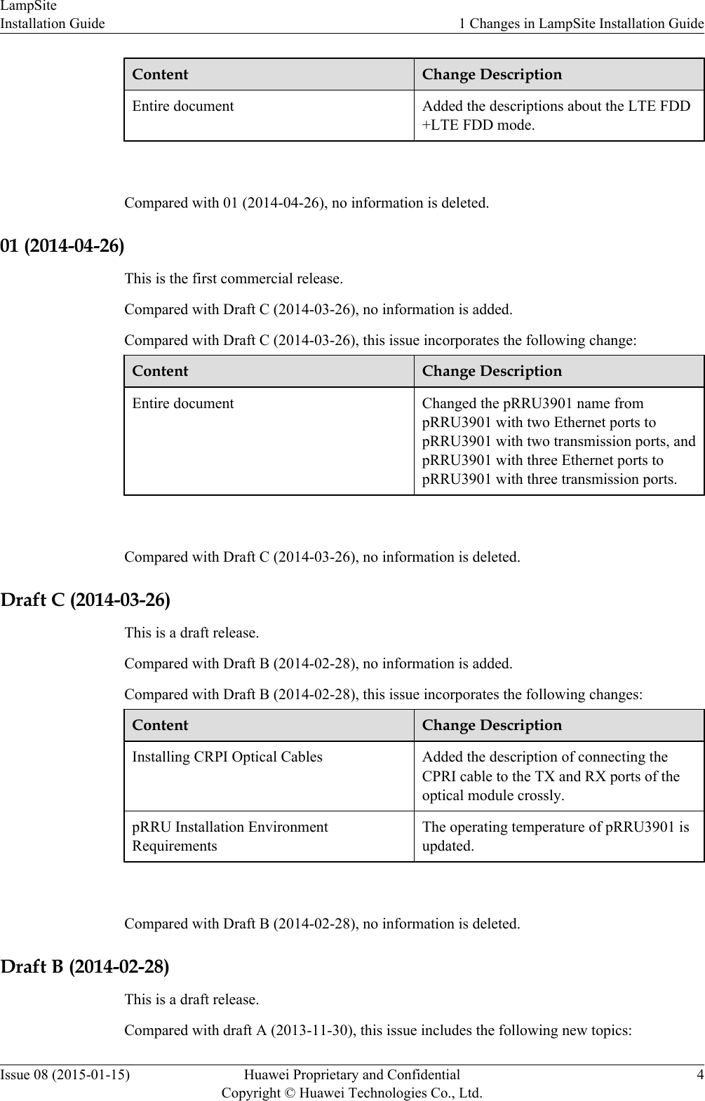
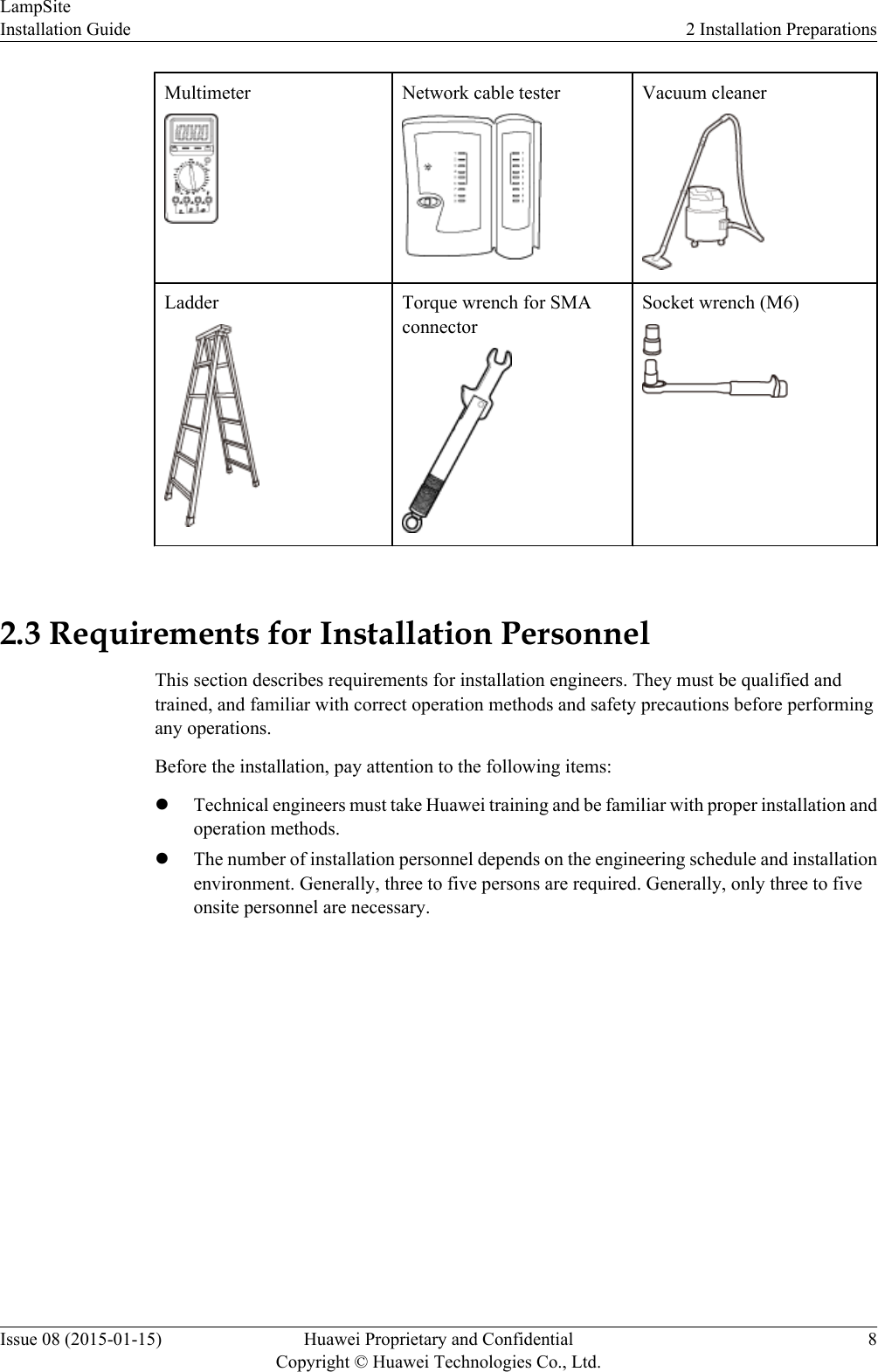
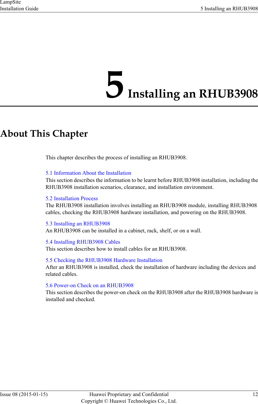
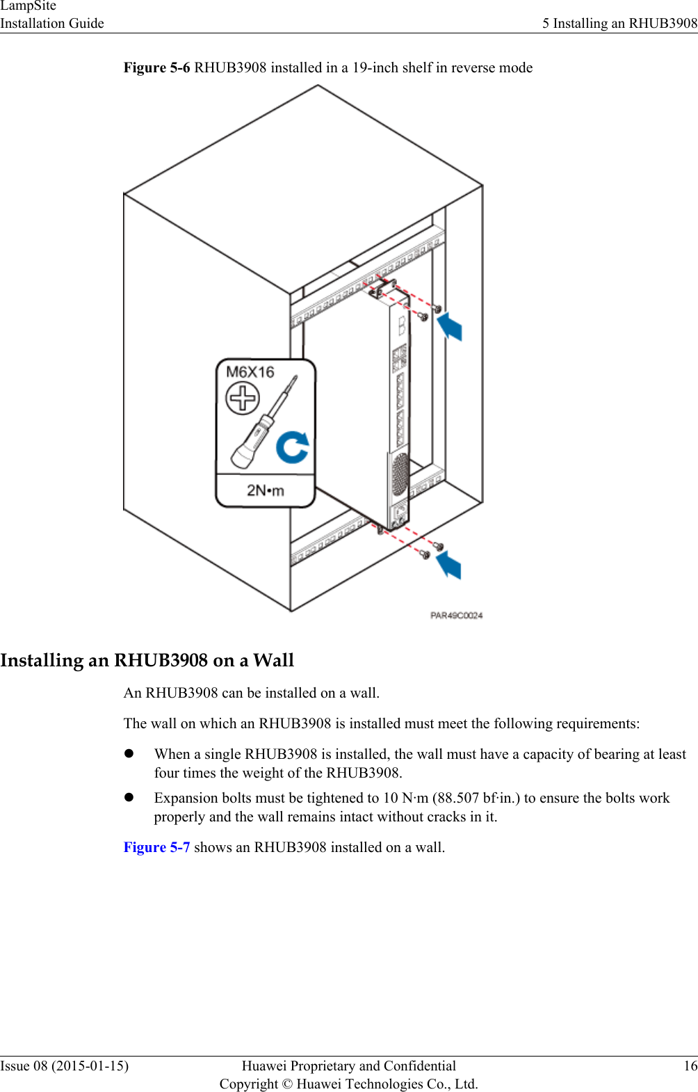
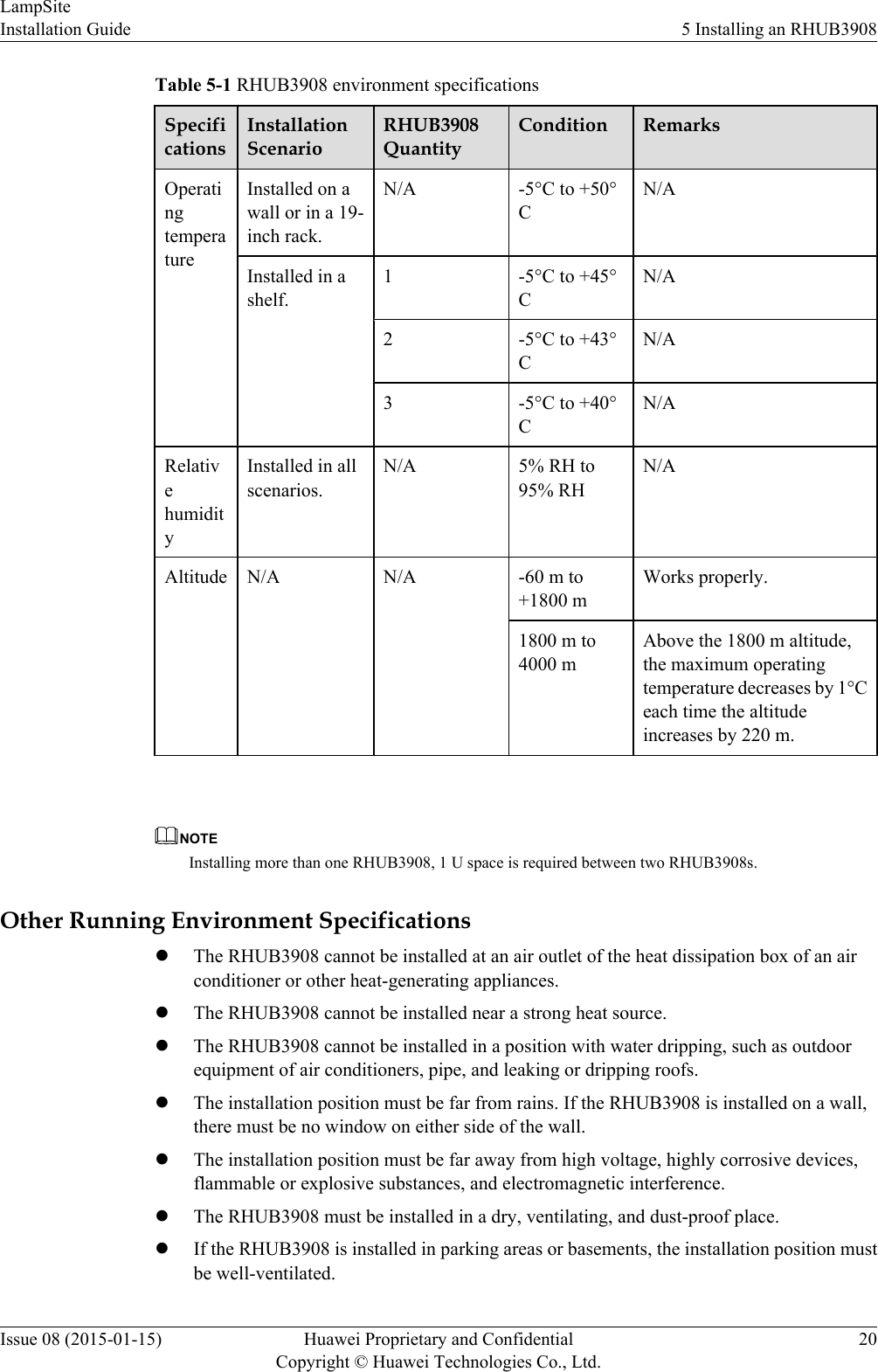
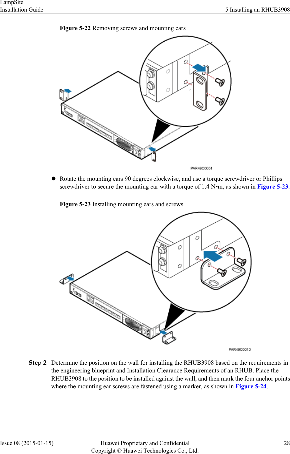
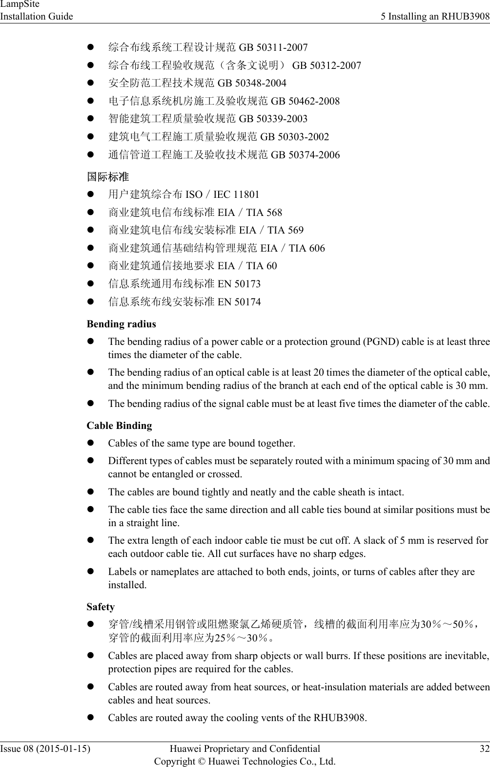
![Symbol DescriptionIndicates a potentially hazardous situation which, if notavoided, could result in equipment damage, data loss,performance deterioration, or unanticipated results.NOTICE is used to address practices not related to personalinjury.Calls attention to important information, best practices andtips.NOTE is used to address information not related to personalinjury, equipment damage, and environment deterioration. General ConventionsThe general conventions that may be found in this document are defined as follows.Convention DescriptionTimes New Roman Normal paragraphs are in Times New Roman.Boldface Names of files, directories, folders, and users are inboldface. For example, log in as user root.Italic Book titles are in italics.Courier New Examples of information displayed on the screen are inCourier New. Command ConventionsThe command conventions that may be found in this document are defined as follows.Convention DescriptionBoldface The keywords of a command line are in boldface.Italic Command arguments are in italics.[ ] Items (keywords or arguments) in brackets [ ] are optional.{ x | y | ... } Optional items are grouped in braces and separated byvertical bars. One item is selected.[ x | y | ... ] Optional items are grouped in brackets and separated byvertical bars. One item is selected or no item is selected.{ x | y | ... }*Optional items are grouped in braces and separated byvertical bars. A minimum of one item or a maximum of allitems can be selected.LampSiteSite Maintenance Guide About This DocumentIssue 05 (2015-01-15) Huawei Proprietary and ConfidentialCopyright © Huawei Technologies Co., Ltd.iv](https://usermanual.wiki/Huawei-Technologies/PRU01P2G6/User-Guide-2703608-Page-122.png)
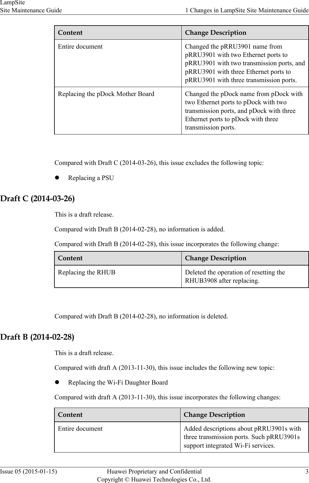
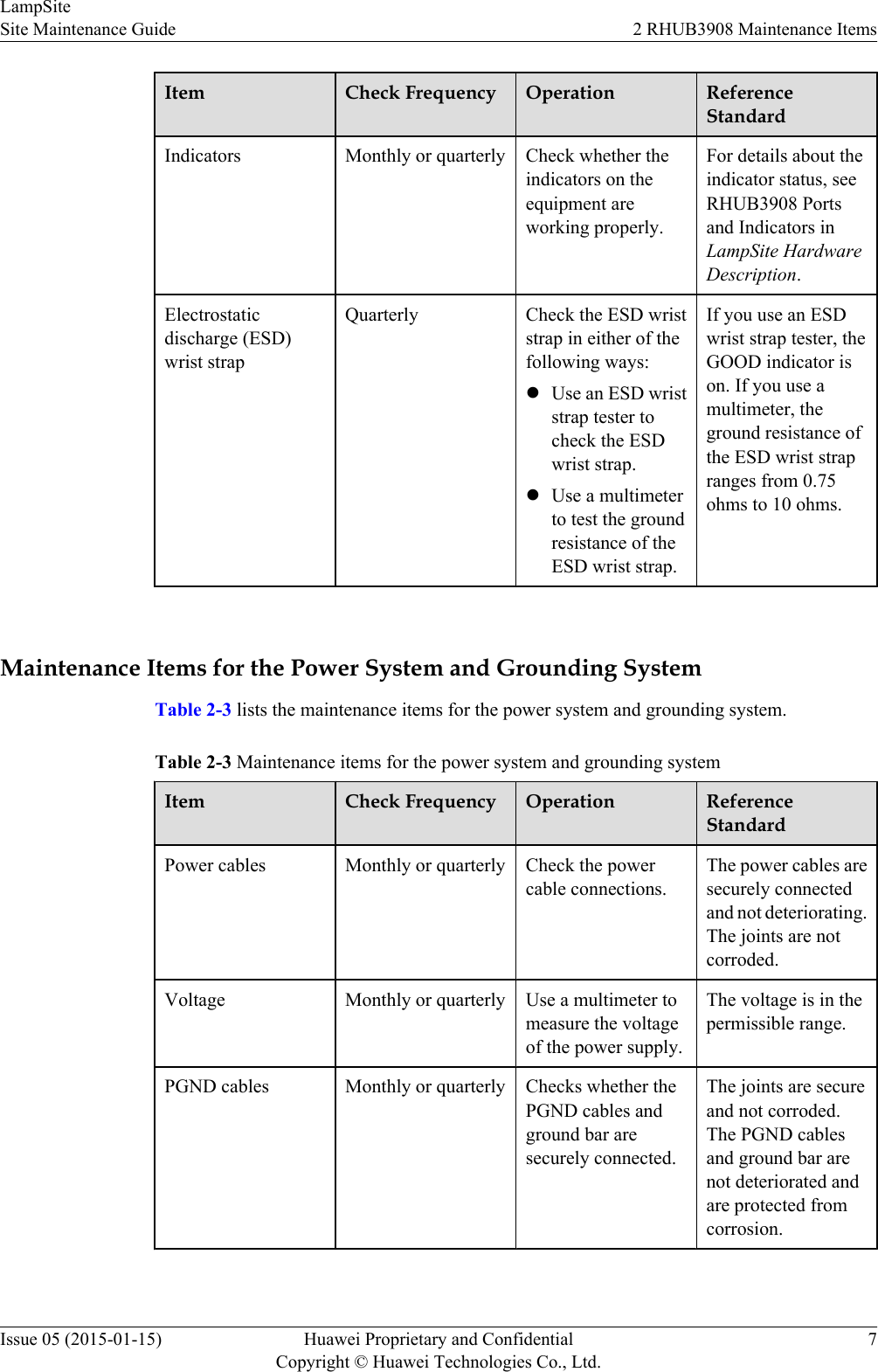
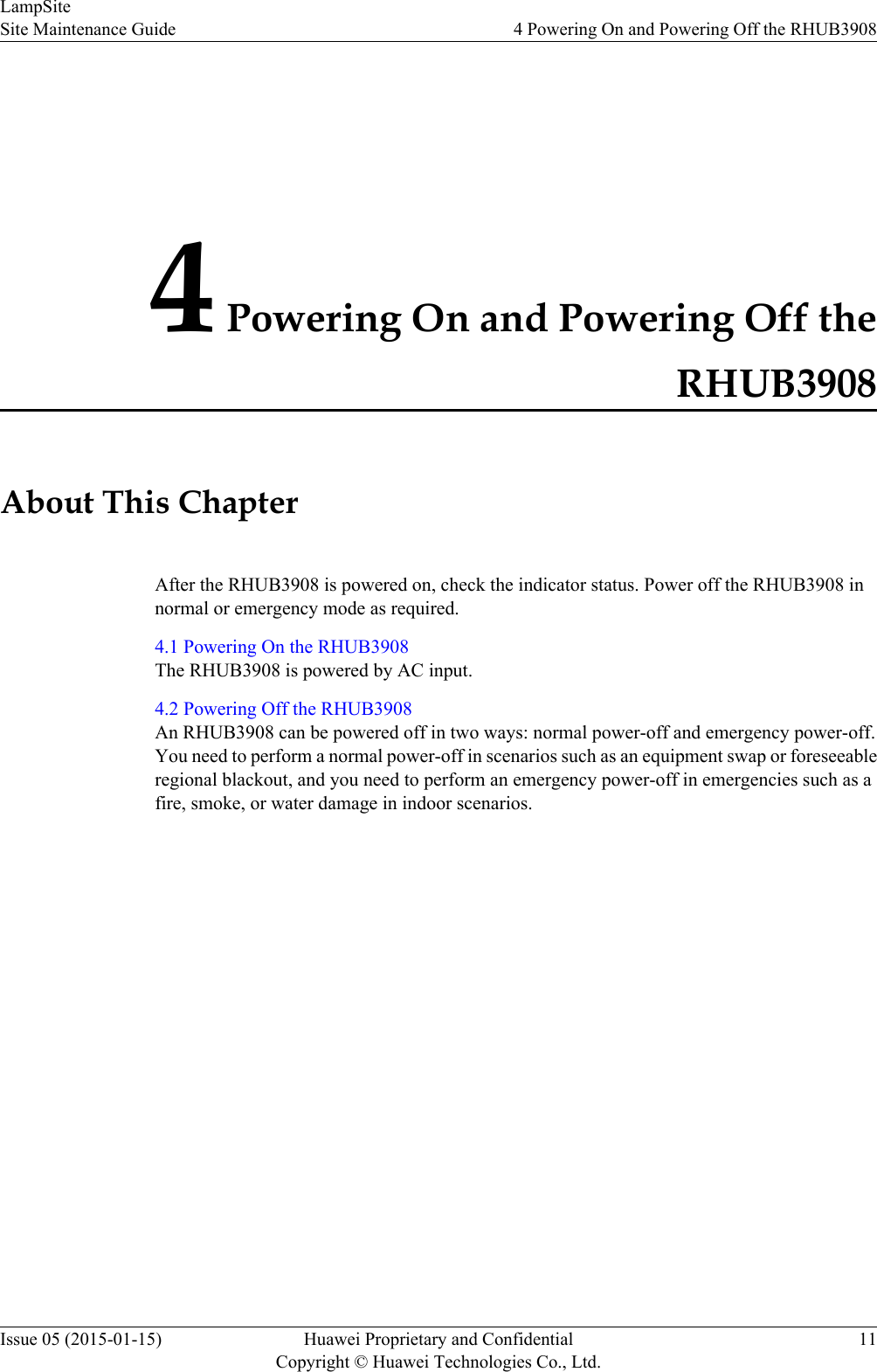
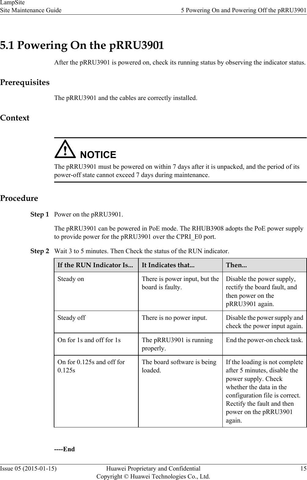
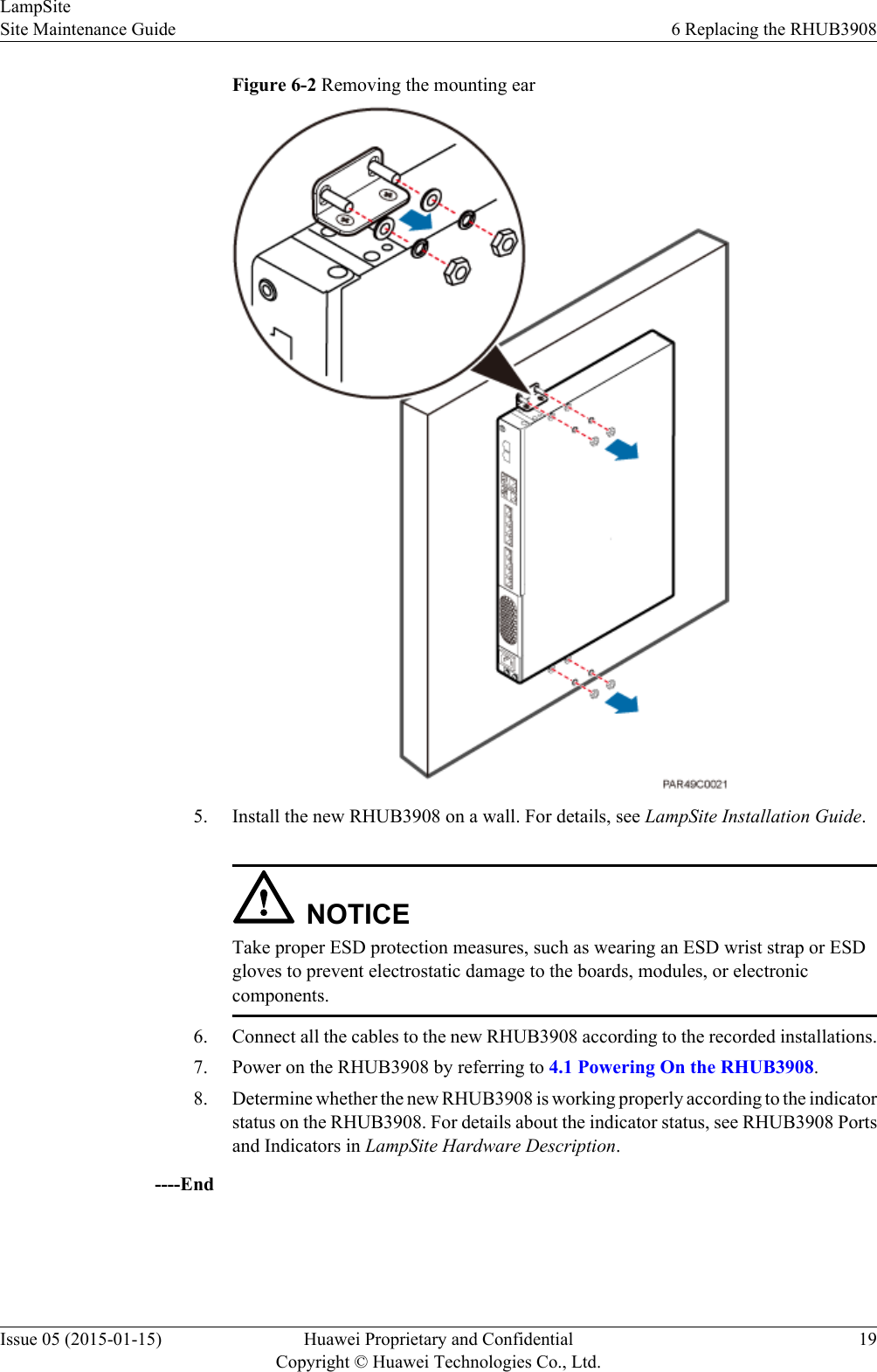
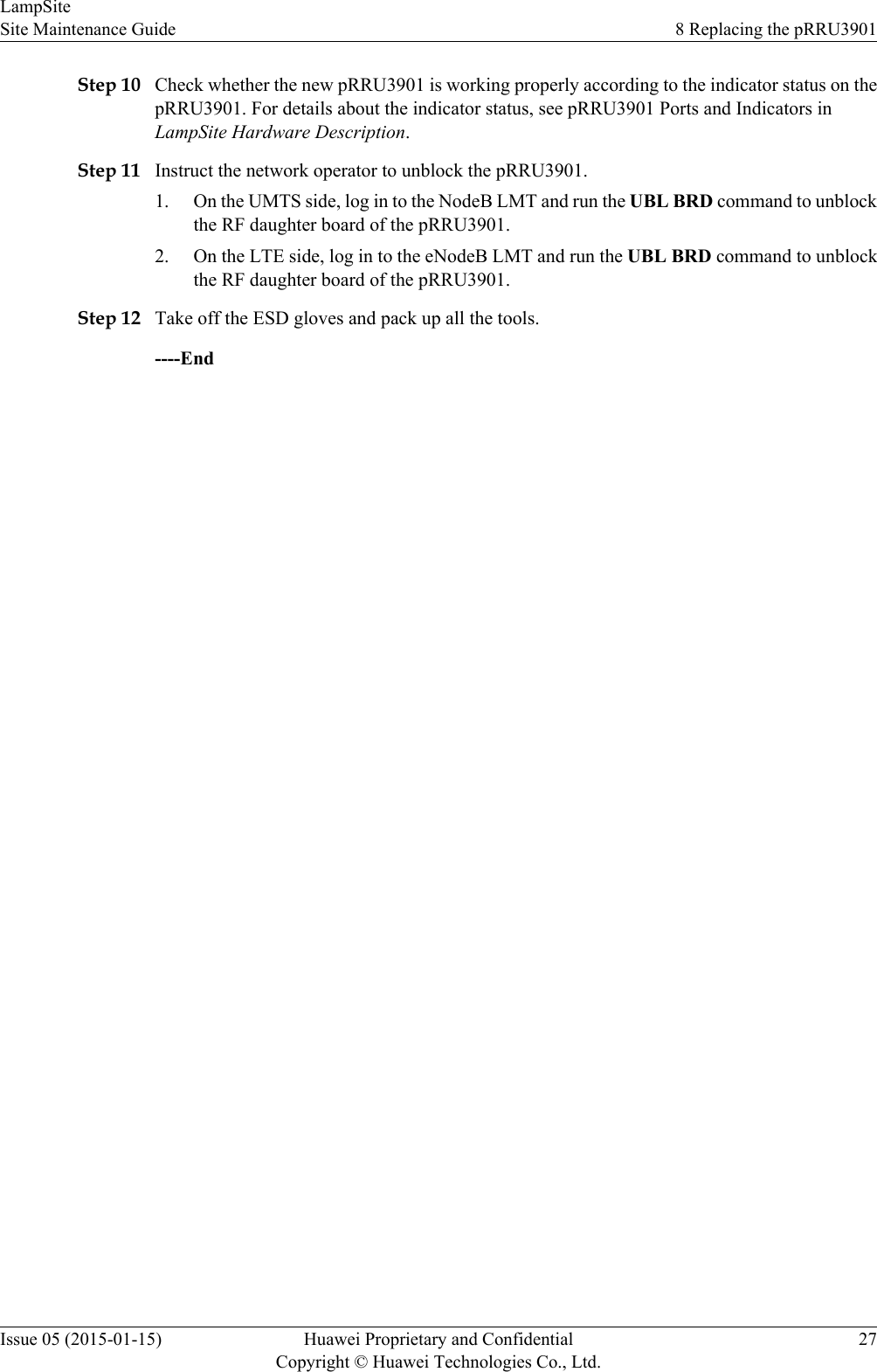
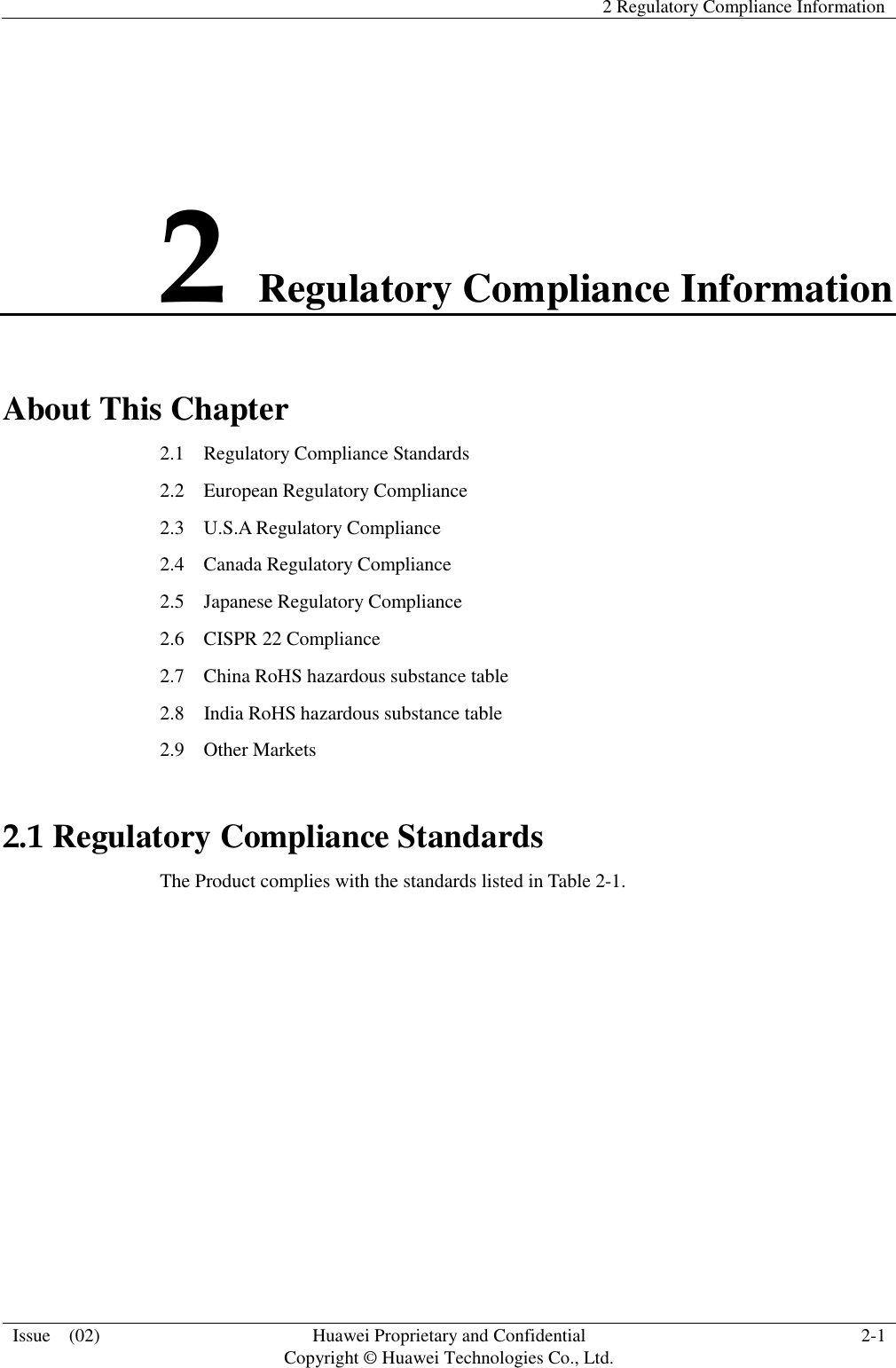
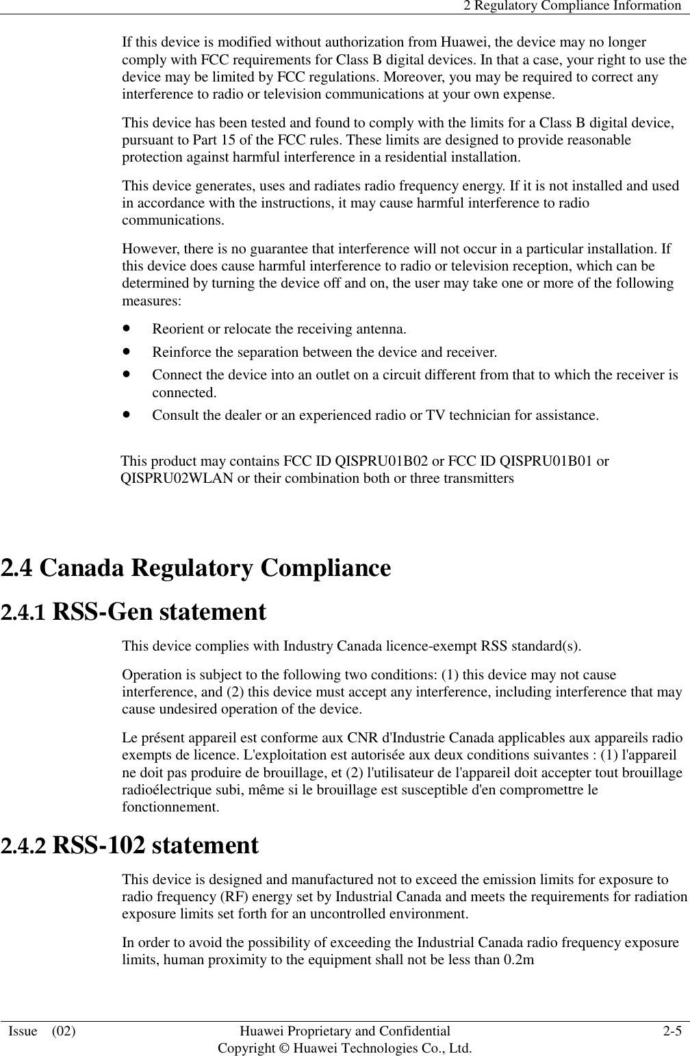
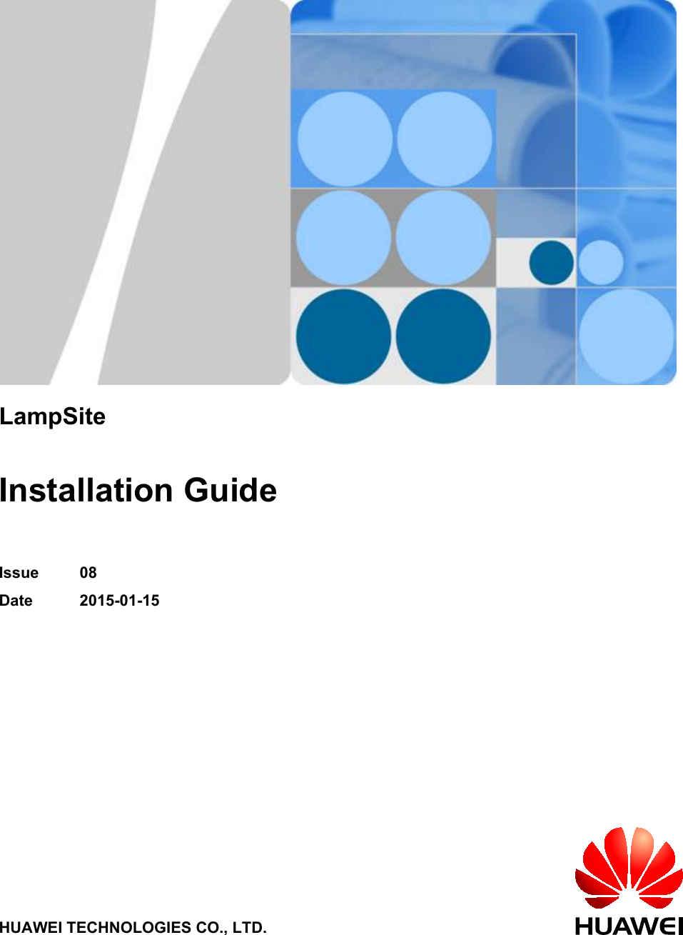
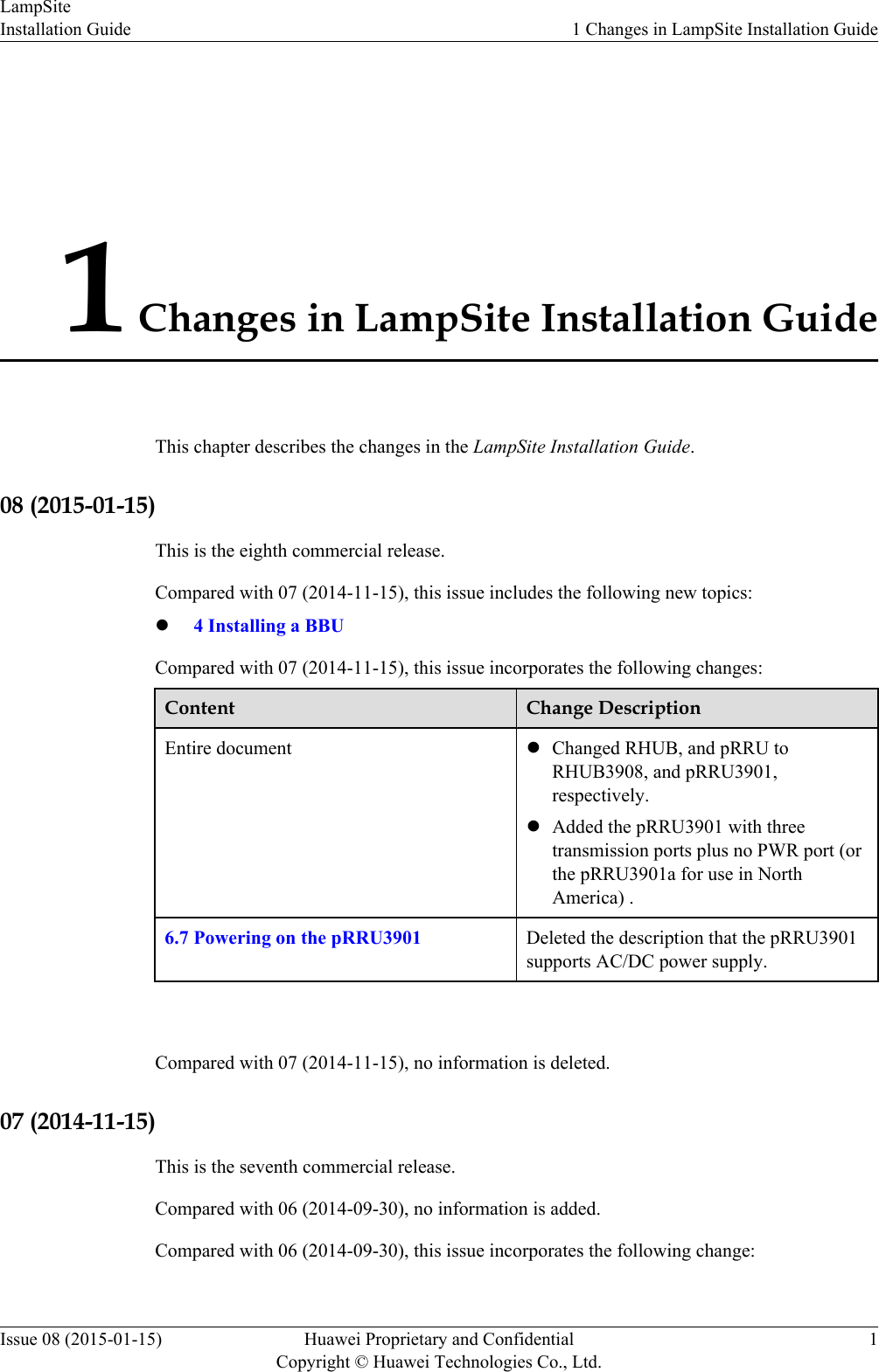
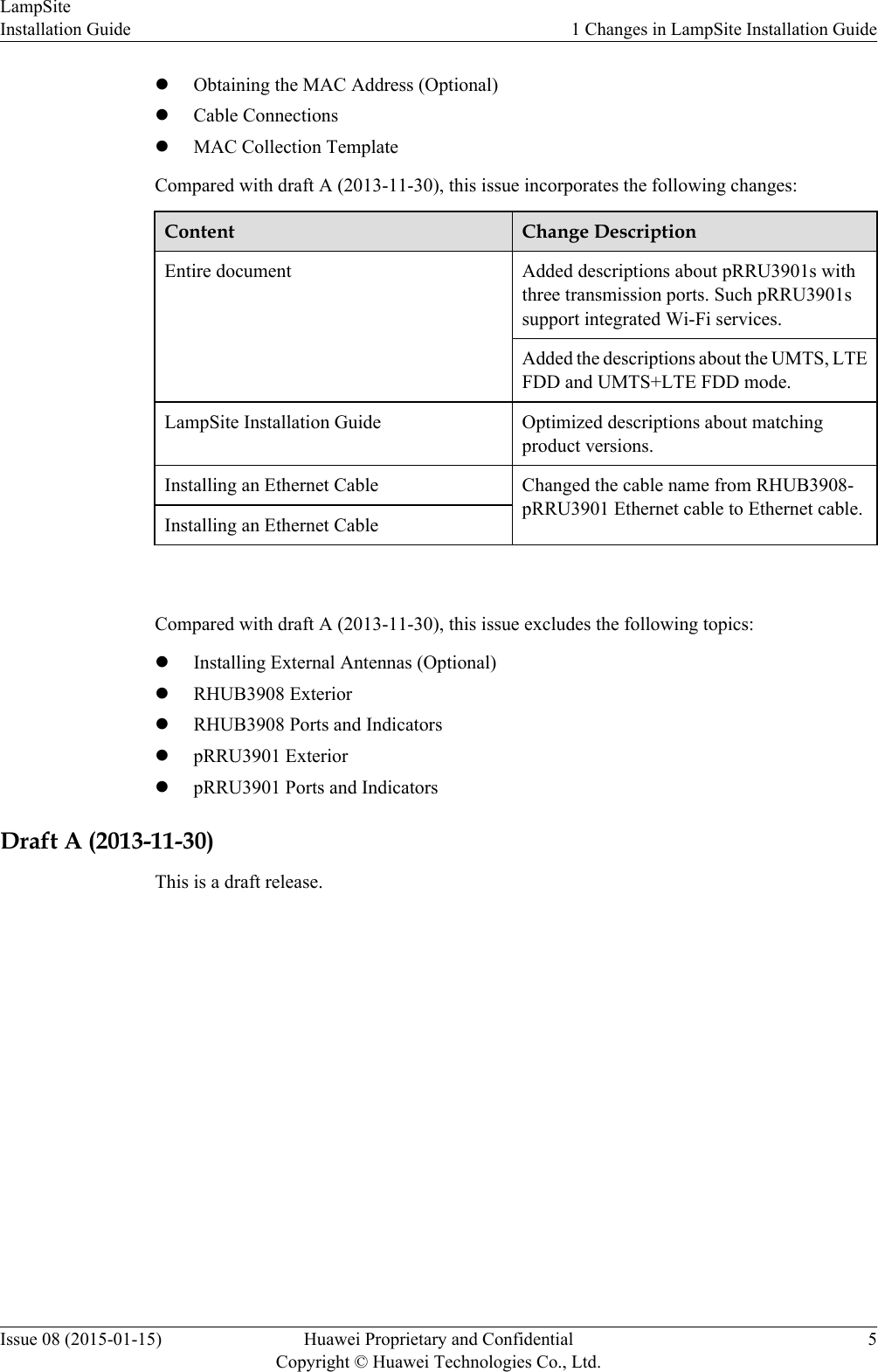
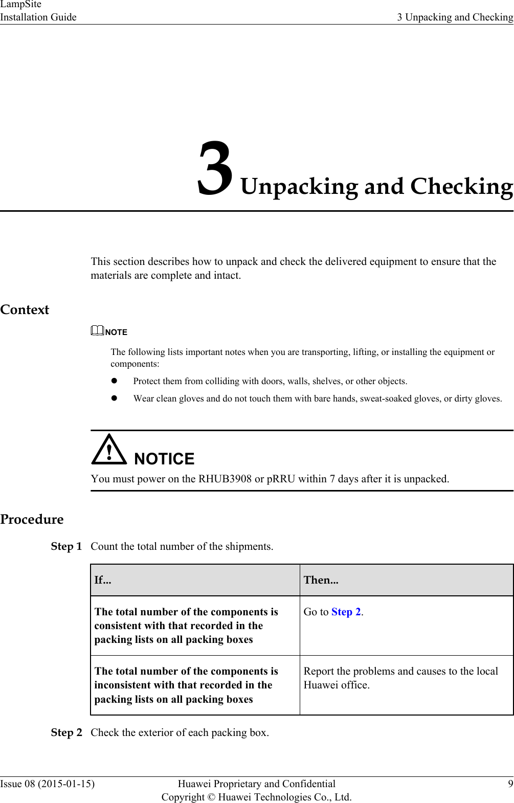
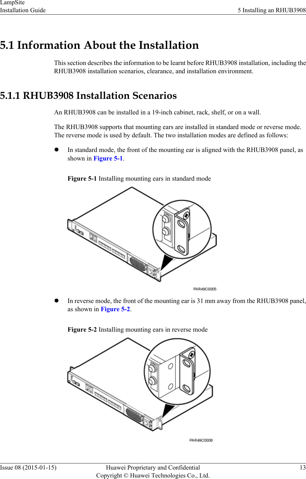
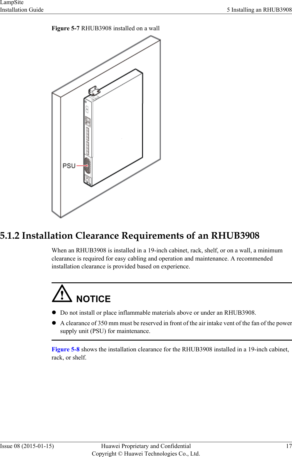
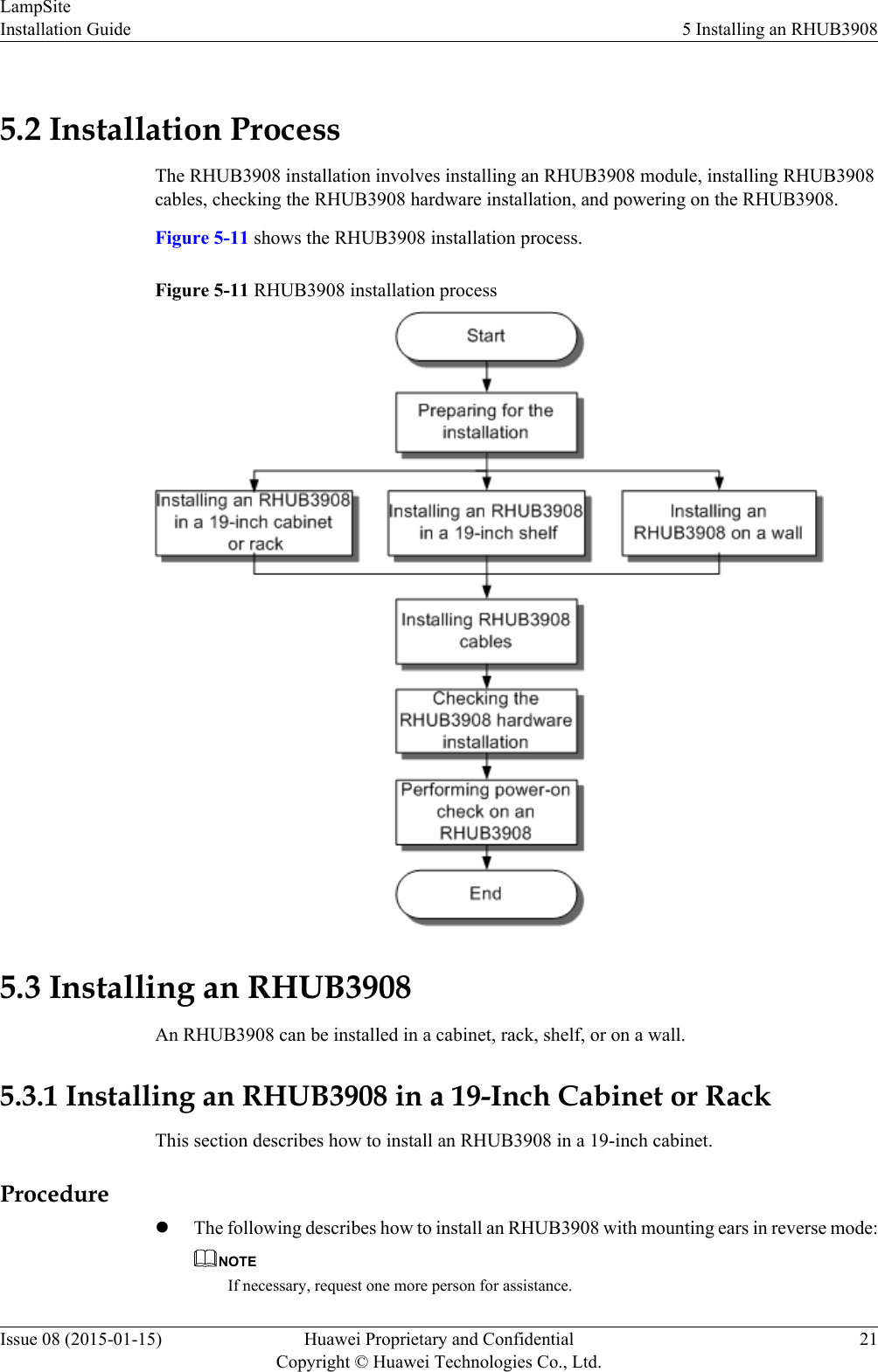
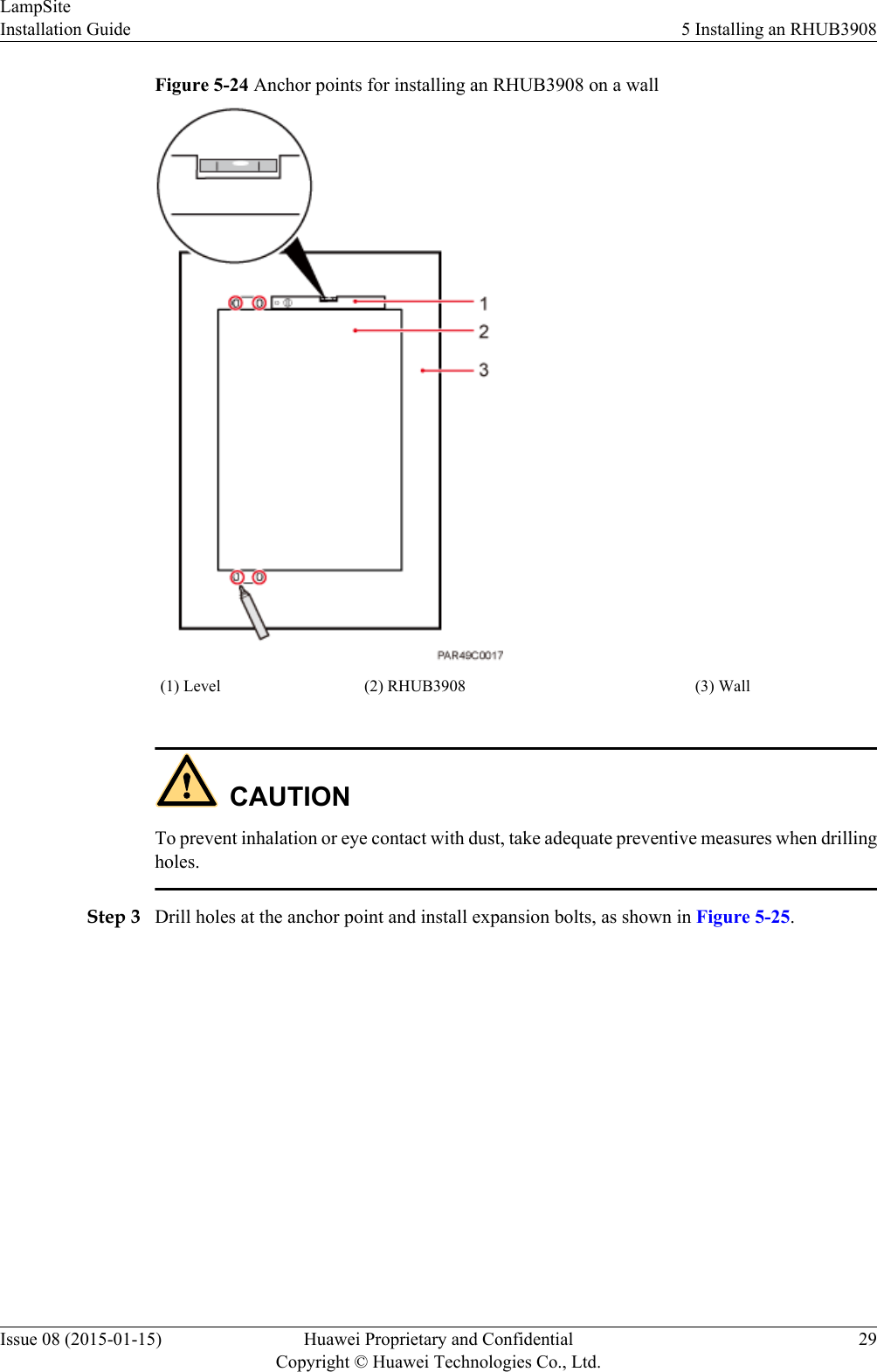
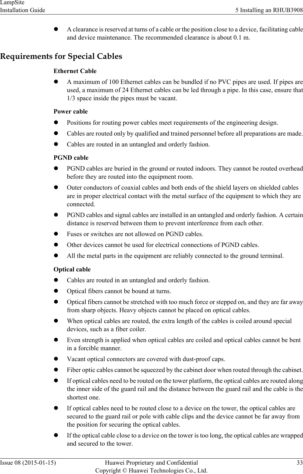
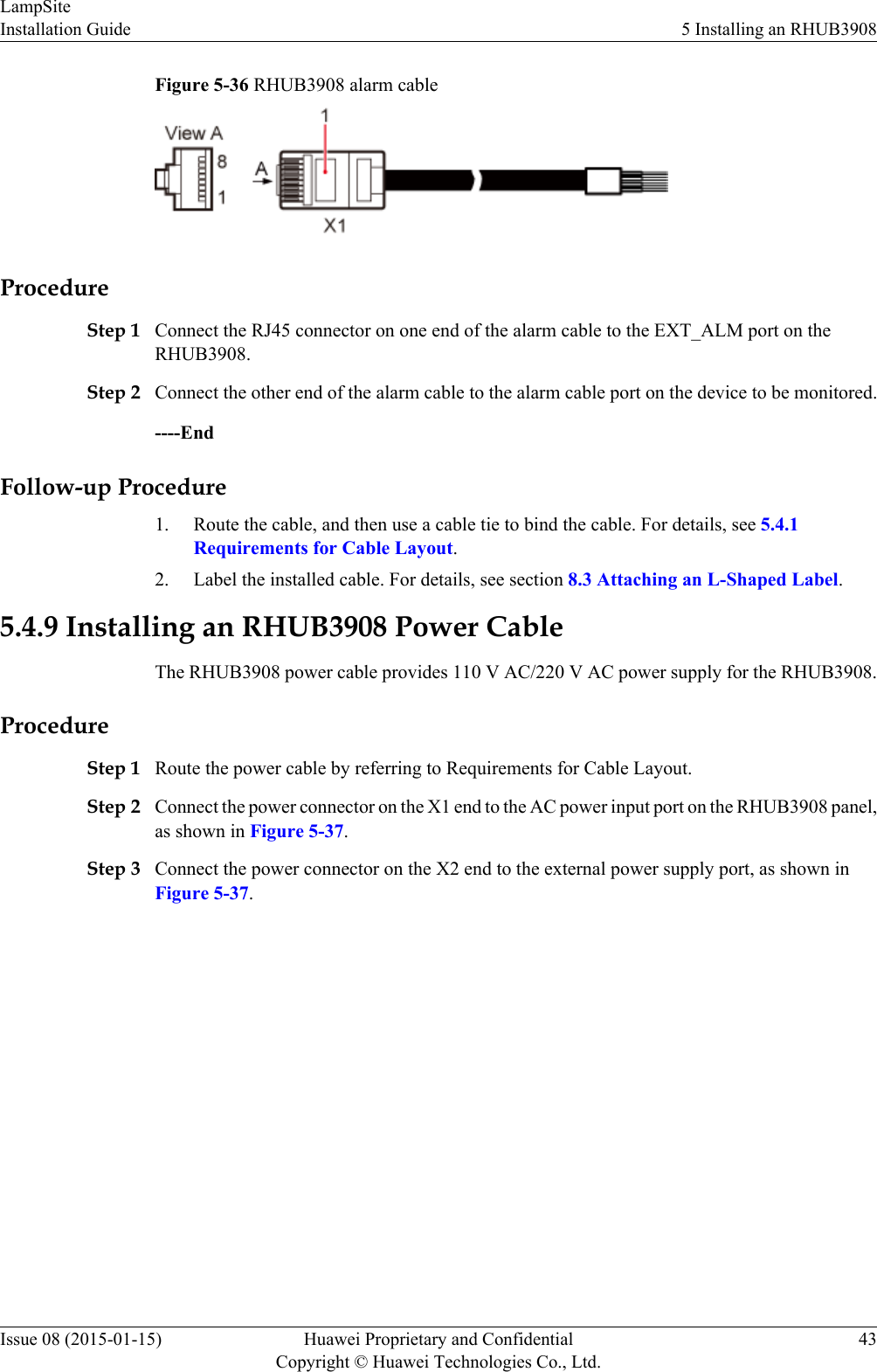
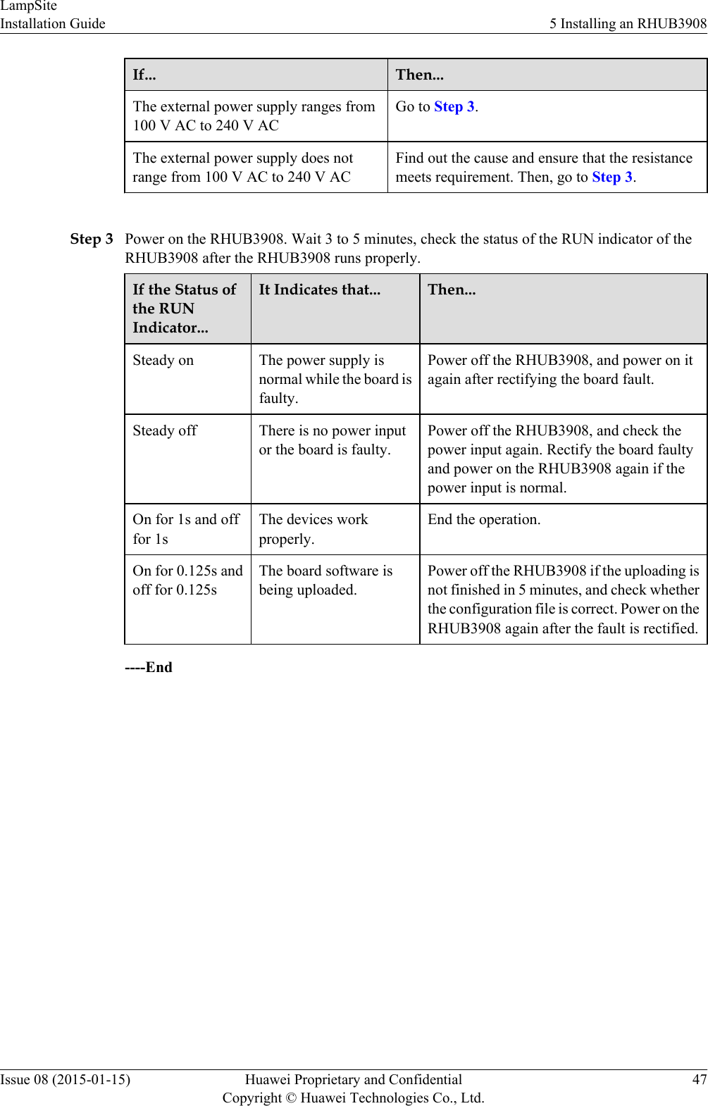
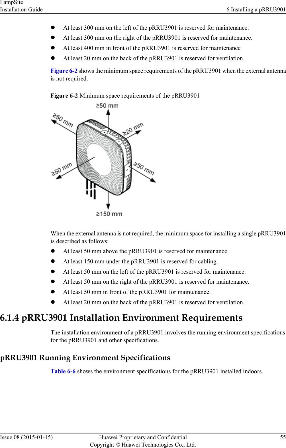
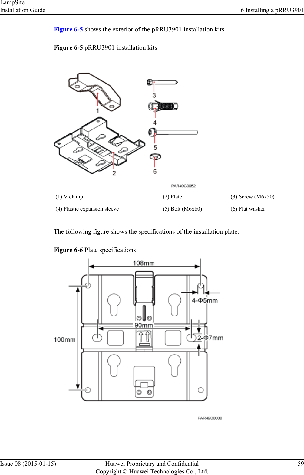
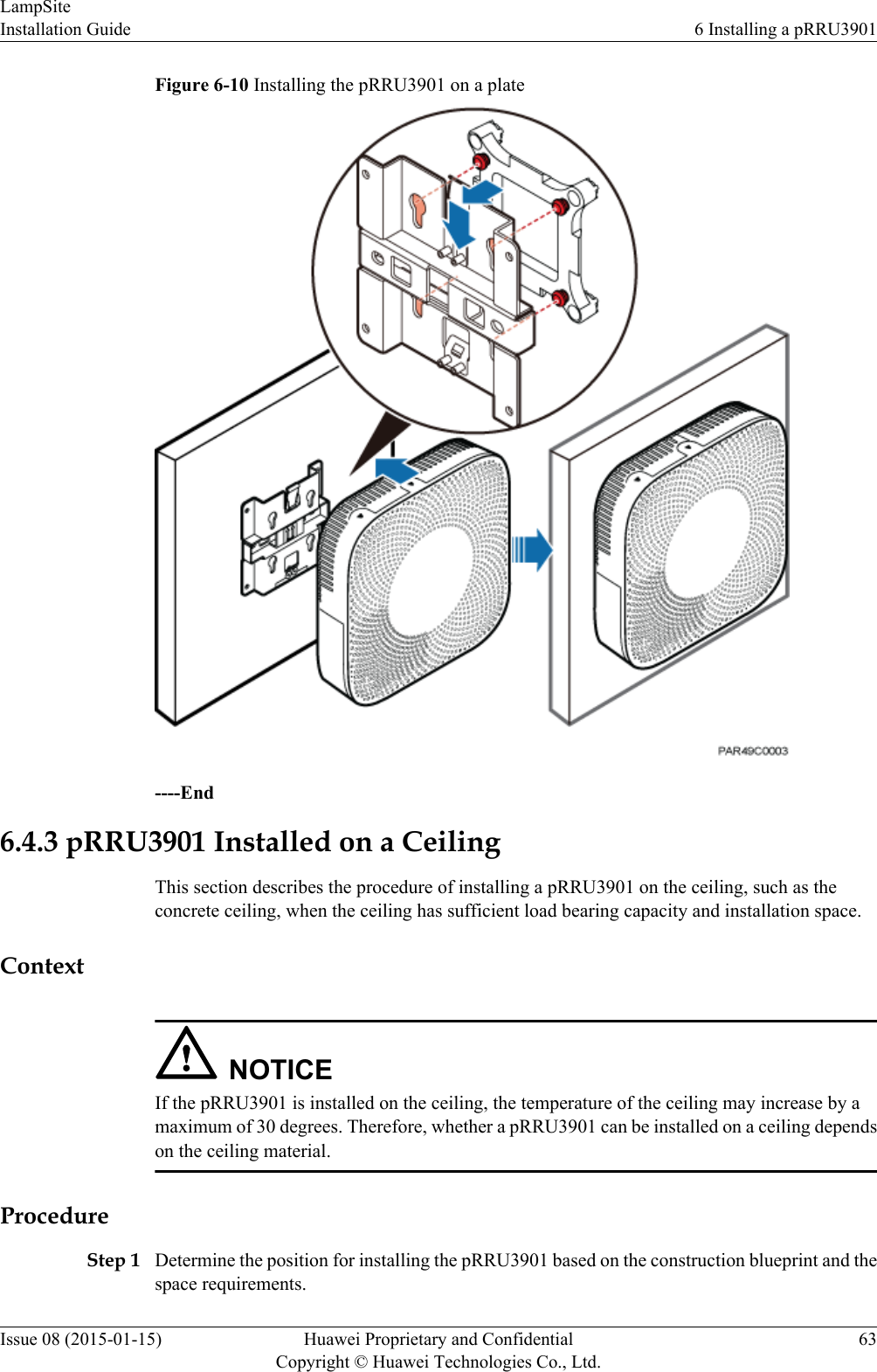
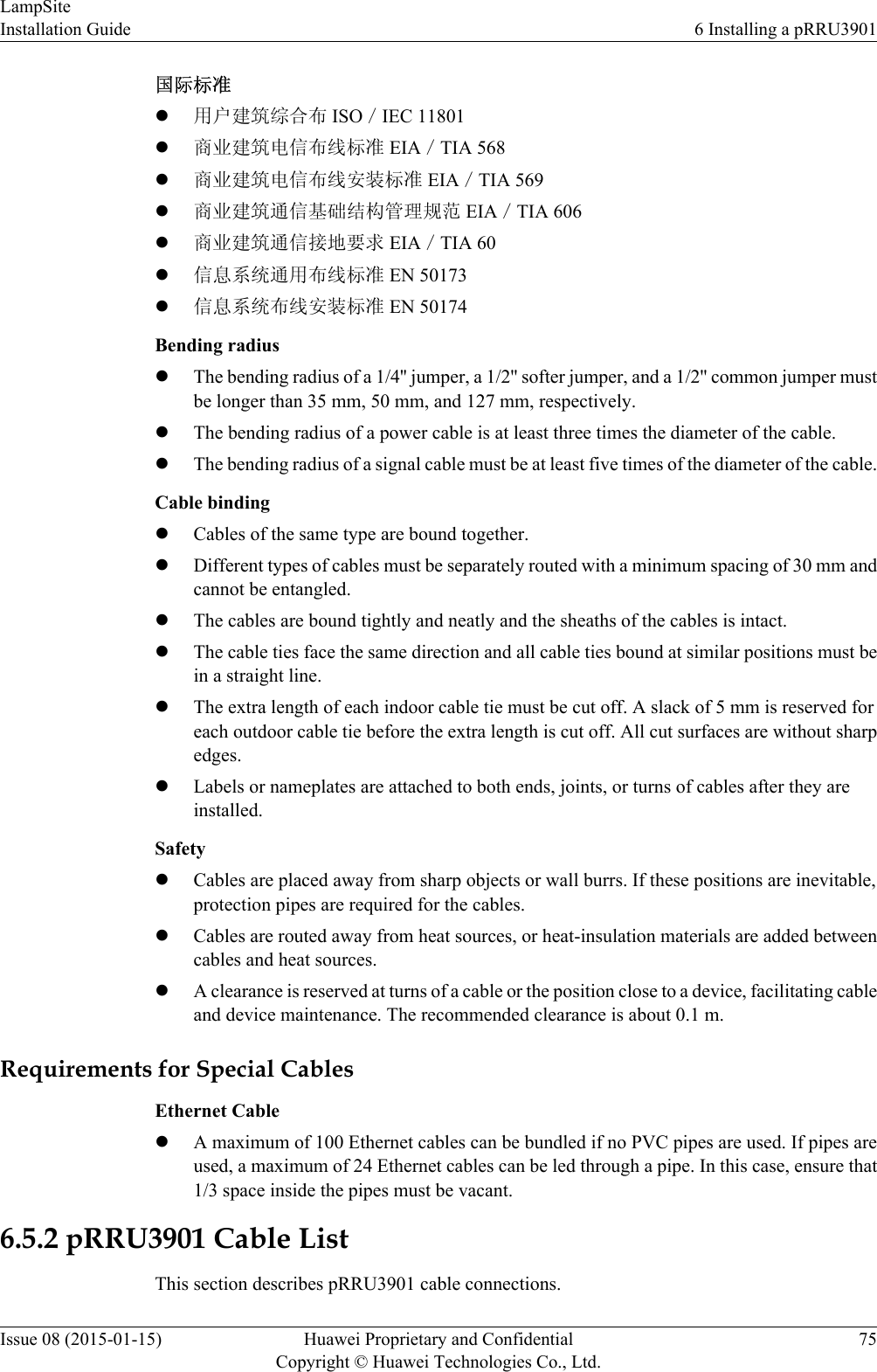
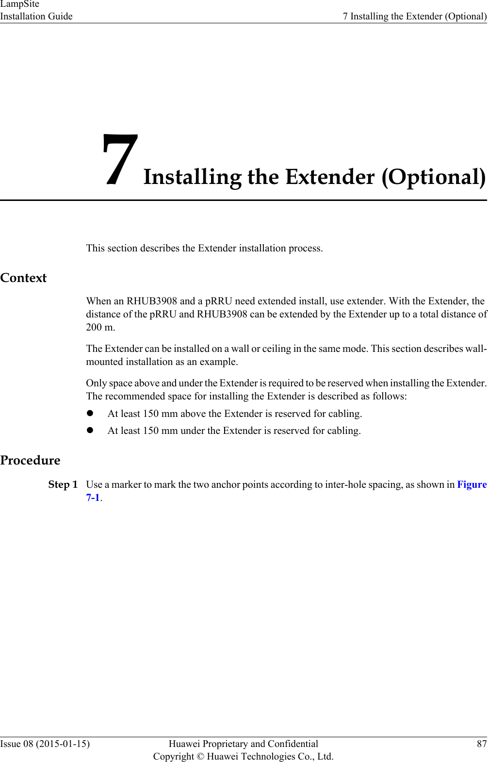
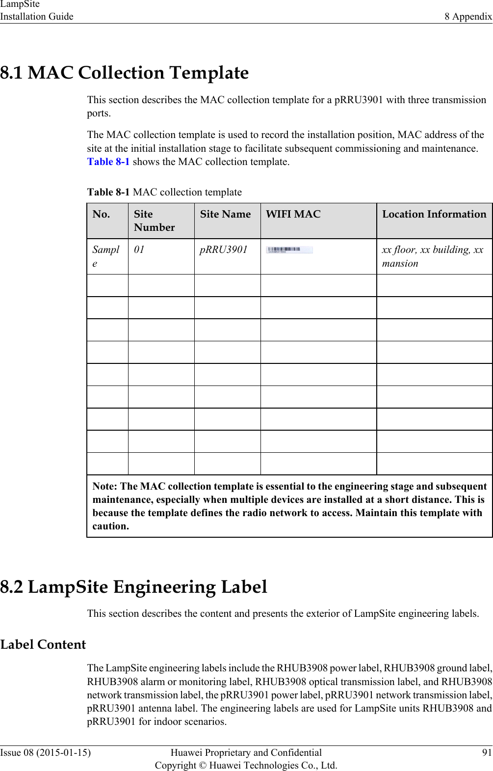
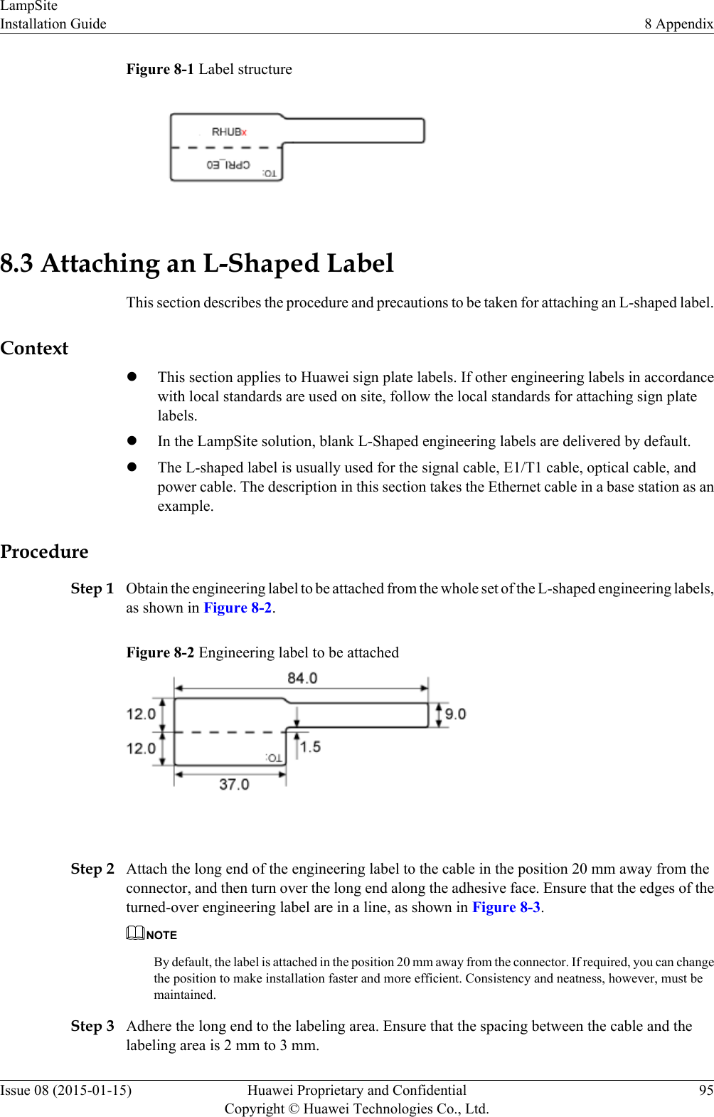
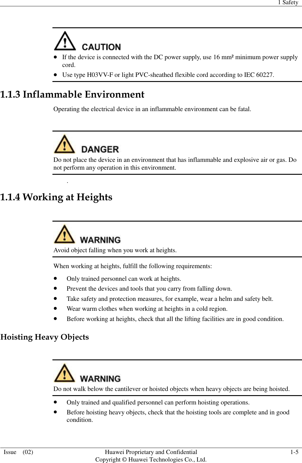
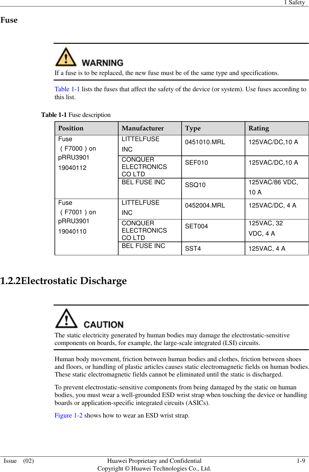
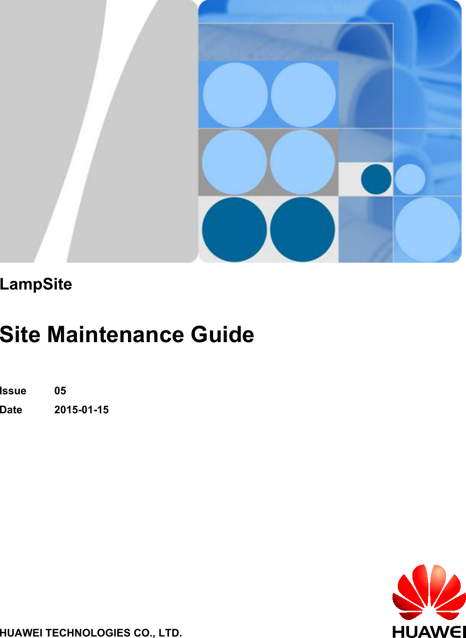
![Convention Description[ x | y | ... ]*Optional items are grouped in brackets and separated byvertical bars. Several items or no item can be selected. GUI ConventionsThe GUI conventions that may be found in this document are defined as follows.Convention DescriptionBoldface Buttons, menus, parameters, tabs, window, and dialog titlesare in boldface. For example, click OK.>Multi-level menus are in boldface and separated by the ">"signs. For example, choose File > Create > Folder. Keyboard OperationsThe keyboard operations that may be found in this document are defined as follows.Format DescriptionKey Press the key. For example, press Enter and press Tab.Key 1+Key 2 Press the keys concurrently. For example, pressing Ctrl+Alt+A means the three keys should be pressed concurrently.Key 1, Key 2 Press the keys in turn. For example, pressing Alt, A meansthe two keys should be pressed in turn. Mouse OperationsThe mouse operations that may be found in this document are defined as follows.Action DescriptionClick Select and release the primary mouse button without movingthe pointer.Double-click Press the primary mouse button twice continuously andquickly without moving the pointer.Drag Press and hold the primary mouse button and move thepointer to a certain position.LampSiteSite Maintenance Guide About This DocumentIssue 05 (2015-01-15) Huawei Proprietary and ConfidentialCopyright © Huawei Technologies Co., Ltd.v](https://usermanual.wiki/Huawei-Technologies/PRU01P2G6/User-Guide-2703608-Page-123.png)