Huawei Technologies PRU01P2G6 pico Remote Radio Unit User Manual 13
Huawei Technologies Co.,Ltd pico Remote Radio Unit 13
13_User Manual

LampSite
Installation Guide
Issue 08
Date 2015-01-15
HUAWEI TECHNOLOGIES CO., LTD.

Copyright © Huawei Technologies Co., Ltd. 2015. All rights reserved.
No part of this document may be reproduced or transmitted in any form or by any means without prior written
consent of Huawei Technologies Co., Ltd.
Trademarks and Permissions
and other Huawei trademarks are trademarks of Huawei Technologies Co., Ltd.
All other trademarks and trade names mentioned in this document are the property of their respective holders.
Notice
The purchased products, services and features are stipulated by the contract made between Huawei and the
customer. All or part of the products, services and features described in this document may not be within the
purchase scope or the usage scope. Unless otherwise specified in the contract, all statements, information,
and recommendations in this document are provided "AS IS" without warranties, guarantees or representations
of any kind, either express or implied.
The information in this document is subject to change without notice. Every effort has been made in the
preparation of this document to ensure accuracy of the contents, but all statements, information, and
recommendations in this document do not constitute a warranty of any kind, express or implied.
Huawei Technologies Co., Ltd.
Address: Huawei Industrial Base
Bantian, Longgang
Shenzhen 518129
People's Republic of China
Website: http://www.huawei.com
Email: support@huawei.com
Issue 08 (2015-01-15) Huawei Proprietary and Confidential
Copyright © Huawei Technologies Co., Ltd.
i
About This Document
Overview
This document describes how to install the modules and cables for the RHUB3908, pRRU3901
indoors. It also provides checklists for hardware installation.
Product Version
The following table lists the product version related to this document.
Product Name Solution Version Product Version
DBS3900 lSRAN9.0 and later versions
lRAN16.0 and later versions
leRAN7.0 and later versions
leRAN TDD 7.0 and later
versions
V100R009C00 and later versions
Intended Audience
This document is intended for:
lBTS installation personnel
LampSite
Installation Guide About This Document
Issue 08 (2015-01-15) Huawei Proprietary and Confidential
Copyright © Huawei Technologies Co., Ltd.
ii

Contents
About This Document.....................................................................................................................ii
1 Changes in LampSite Installation Guide.................................................................................1
2 Installation Preparations..............................................................................................................6
2.1 Reference Documents.....................................................................................................................................................7
2.2 Preparing Tools and Instruments....................................................................................................................................7
2.3 Requirements for Installation Personnel.........................................................................................................................8
3 Unpacking and Checking............................................................................................................9
4 Installing a BBU...........................................................................................................................11
5 Installing an RHUB3908.............................................................................................................12
5.1 Information About the Installation...............................................................................................................................13
5.1.1 RHUB3908 Installation Scenarios.............................................................................................................................13
5.1.2 Installation Clearance Requirements of an RHUB3908............................................................................................17
5.1.3 Installation Environment of an RHUB3908..............................................................................................................19
5.2 Installation Process.......................................................................................................................................................21
5.3 Installing an RHUB3908..............................................................................................................................................21
5.3.1 Installing an RHUB3908 in a 19-Inch Cabinet or Rack............................................................................................21
5.3.2 Installing an RHUB3908 in a 19-Inch Shelf.............................................................................................................24
5.3.3 Installing an RHUB3908 on a Wall...........................................................................................................................27
5.4 Installing RHUB3908 Cables.......................................................................................................................................31
5.4.1 Requirements for Cable Layout.................................................................................................................................31
5.4.2 RHUB3908 Cable List...............................................................................................................................................34
5.4.3 Cable Connections.....................................................................................................................................................35
5.4.4 RHUB3908 Cable Installation Process......................................................................................................................35
5.4.5 Installing an RHUB3908 PGND Cable.....................................................................................................................36
5.4.6 Installing an Ethernet Cable......................................................................................................................................38
5.4.7 Installing CRPI Optical Cables..................................................................................................................................40
5.4.8 Installing an RHUB3908 Alarm Cable (Optional)....................................................................................................42
5.4.9 Installing an RHUB3908 Power Cable......................................................................................................................43
5.5 Checking the RHUB3908 Hardware Installation.........................................................................................................44
5.6 Power-on Check on an RHUB3908..............................................................................................................................46
LampSite
Installation Guide Contents
Issue 08 (2015-01-15) Huawei Proprietary and Confidential
Copyright © Huawei Technologies Co., Ltd.
iii

6 Installing a pRRU3901................................................................................................................48
6.1 Information About the Installation...............................................................................................................................50
6.1.1 pRRU3901 Product Family.......................................................................................................................................50
6.1.2 pRRU3901 Installation Scenario...............................................................................................................................50
6.1.3 Space Requirements..................................................................................................................................................54
6.1.4 pRRU3901 Installation Environment Requirements.................................................................................................55
6.2 Obtaining the MAC Address (Optional) .....................................................................................................................56
6.3 Installation Process.......................................................................................................................................................57
6.4 Installing a pRRU3901.................................................................................................................................................58
6.4.1 pRRU3901 Installation Kits......................................................................................................................................58
6.4.2 pRRU3901 Installed on a Wall..................................................................................................................................60
6.4.3 pRRU3901 Installed on a Ceiling..............................................................................................................................63
6.4.4 pRRU3901 Installed on a Pole..................................................................................................................................66
6.4.5 pRRU3901 Installed on a Plate.................................................................................................................................68
6.4.6 pRRU3901 Installed on a Keel..................................................................................................................................71
6.5 Installing pRRU3901 Cables........................................................................................................................................74
6.5.1 Requirements for Cable Layout.................................................................................................................................74
6.5.2 pRRU3901 Cable List...............................................................................................................................................75
6.5.3 Cable Connections.....................................................................................................................................................76
6.5.4 Cable Connections (LTE TDD).................................................................................................................................79
6.5.5 pRRU3901 cable installation process........................................................................................................................80
6.5.6 Installing an Ethernet Cable......................................................................................................................................80
6.5.7 Installing pRRU3901 Jumpers (Optional).................................................................................................................82
6.6 Checking the pRRU3901 Hardware Installation..........................................................................................................84
6.7 Powering on the pRRU3901.........................................................................................................................................85
7 Installing the Extender (Optional)...........................................................................................87
8 Appendix.......................................................................................................................................90
8.1 MAC Collection Template...........................................................................................................................................91
8.2 LampSite Engineering Label........................................................................................................................................91
8.3 Attaching an L-Shaped Label.......................................................................................................................................95
LampSite
Installation Guide Contents
Issue 08 (2015-01-15) Huawei Proprietary and Confidential
Copyright © Huawei Technologies Co., Ltd.
iv
1 Changes in LampSite Installation Guide
This chapter describes the changes in the LampSite Installation Guide.
08 (2015-01-15)
This is the eighth commercial release.
Compared with 07 (2014-11-15), this issue includes the following new topics:
l4 Installing a BBU
Compared with 07 (2014-11-15), this issue incorporates the following changes:
Content Change Description
Entire document lChanged RHUB, and pRRU to
RHUB3908, and pRRU3901,
respectively.
lAdded the pRRU3901 with three
transmission ports plus no PWR port (or
the pRRU3901a for use in North
America) .
6.7 Powering on the pRRU3901 Deleted the description that the pRRU3901
supports AC/DC power supply.
Compared with 07 (2014-11-15), no information is deleted.
07 (2014-11-15)
This is the seventh commercial release.
Compared with 06 (2014-09-30), no information is added.
Compared with 06 (2014-09-30), this issue incorporates the following change:
LampSite
Installation Guide 1 Changes in LampSite Installation Guide
Issue 08 (2015-01-15) Huawei Proprietary and Confidential
Copyright © Huawei Technologies Co., Ltd.
1
Content Change Description
Space Requirements Added the requirements on the installation space
when the pRRU3901 working on the 2.6 GHz band
and the Wi-Fi module need to process services
concurrently.
Compared with 06 (2014-09-30), this issue excludes the following topic:
lInstalling RF Daughter Boards on a pRRU3901 (in Capacity Expansion Scenarios)
06 (2014-09-30)
This is the sixth commercial release.
Compared with 05 (2014-08-30), no information is added.
Compared with 05 (2014-08-30), this issue incorporates the following changes:
Content Change Description
pRRU Installation Environment
Requirements
Changed the operating temperature of
pRRU3901s to a range from - 5°C to + 40°C.
Requirements for Cable Layout Added the cabling requirements for Ethernet
cables.
Requirements for Cable Layout
Compared with 05 (2014-08-30), no information is deleted.
05 (2014-08-30)
This is the fifth commercial release.
Compared with 04 (2014-07-30), no information is added.
Compared with 04 (2014-07-30), this issue incorporates the following changes:
Content Change Description
Installation Clearance Requirements of an
RHUB
Added the security precautions for the
RHUB3908 installation environment.
Requirements for Cable Layout
Installing an Ethernet Cable Added the Ethernet cable specifications and
requirements on flame spread rating.
Installing an Ethernet Cable
Compared with 04 (2014-07-30), no information is deleted.
LampSite
Installation Guide 1 Changes in LampSite Installation Guide
Issue 08 (2015-01-15) Huawei Proprietary and Confidential
Copyright © Huawei Technologies Co., Ltd.
2
04 (2014-07-30)
This is the fourth commercial release.
Compared with 03 (2014-06-30), no information is added.
Compared with 03 (2014-06-30), this issue incorporates the following change:
Content Change Description
7 Installing the Extender (Optional) Added the descriptions about installing a
Extender on a Ceiling.
Compared with 03 (2014-06-30), no information is deleted.
03 (2014-06-30)
This is the third commercial release.
Compared with 02 (2014-05-30), this issue includes the following new topics:
l8.2 LampSite Engineering Label
l8.3 Attaching an L-Shaped Label
Compared with 02 (2014-05-30), this issue incorporates the following changes:
Content Change Description
Cable Connections Modified the description about cable
connections of the RHUB3908.
Installing RHUB Cables Added the steps for attaching labels to cables.
Installing pRRU Cables
Installing an Ethernet Cable Added the steps for making Ethernet cables.
Installing an Ethernet Cable
Installing RF Daughter Boards on a
pRRU3901 (in Capacity Expansion
Scenarios)
Added the descriptions about the supported
block type.
Compared with 02 (2014-05-30), no information is deleted.
02 (2014-05-30)
This is the second commercial release.
Compared with 01 (2014-04-26), no information is added.
Compared with 01 (2014-04-26), this issue incorporates the following change:
LampSite
Installation Guide 1 Changes in LampSite Installation Guide
Issue 08 (2015-01-15) Huawei Proprietary and Confidential
Copyright © Huawei Technologies Co., Ltd.
3
Content Change Description
Entire document Added the descriptions about the LTE FDD
+LTE FDD mode.
Compared with 01 (2014-04-26), no information is deleted.
01 (2014-04-26)
This is the first commercial release.
Compared with Draft C (2014-03-26), no information is added.
Compared with Draft C (2014-03-26), this issue incorporates the following change:
Content Change Description
Entire document Changed the pRRU3901 name from
pRRU3901 with two Ethernet ports to
pRRU3901 with two transmission ports, and
pRRU3901 with three Ethernet ports to
pRRU3901 with three transmission ports.
Compared with Draft C (2014-03-26), no information is deleted.
Draft C (2014-03-26)
This is a draft release.
Compared with Draft B (2014-02-28), no information is added.
Compared with Draft B (2014-02-28), this issue incorporates the following changes:
Content Change Description
Installing CRPI Optical Cables Added the description of connecting the
CPRI cable to the TX and RX ports of the
optical module crossly.
pRRU Installation Environment
Requirements
The operating temperature of pRRU3901 is
updated.
Compared with Draft B (2014-02-28), no information is deleted.
Draft B (2014-02-28)
This is a draft release.
Compared with draft A (2013-11-30), this issue includes the following new topics:
LampSite
Installation Guide 1 Changes in LampSite Installation Guide
Issue 08 (2015-01-15) Huawei Proprietary and Confidential
Copyright © Huawei Technologies Co., Ltd.
4
lObtaining the MAC Address (Optional)
lCable Connections
lMAC Collection Template
Compared with draft A (2013-11-30), this issue incorporates the following changes:
Content Change Description
Entire document Added descriptions about pRRU3901s with
three transmission ports. Such pRRU3901s
support integrated Wi-Fi services.
Added the descriptions about the UMTS, LTE
FDD and UMTS+LTE FDD mode.
LampSite Installation Guide Optimized descriptions about matching
product versions.
Installing an Ethernet Cable Changed the cable name from RHUB3908-
pRRU3901 Ethernet cable to Ethernet cable.
Installing an Ethernet Cable
Compared with draft A (2013-11-30), this issue excludes the following topics:
lInstalling External Antennas (Optional)
lRHUB3908 Exterior
lRHUB3908 Ports and Indicators
lpRRU3901 Exterior
lpRRU3901 Ports and Indicators
Draft A (2013-11-30)
This is a draft release.
LampSite
Installation Guide 1 Changes in LampSite Installation Guide
Issue 08 (2015-01-15) Huawei Proprietary and Confidential
Copyright © Huawei Technologies Co., Ltd.
5

2 Installation Preparations
About This Chapter
Before starting the installation, you must obtain the required reference documents, tools, and
instruments, and familiarize yourself with the skills required.
2.1 Reference Documents
Before the installation, you must read the following documents:
2.2 Preparing Tools and Instruments
This section describes the tools and instruments that must be prepared before the installation.
2.3 Requirements for Installation Personnel
This section describes requirements for installation engineers. They must be qualified and
trained, and familiar with correct operation methods and safety precautions before performing
any operations.
LampSite
Installation Guide 2 Installation Preparations
Issue 08 (2015-01-15) Huawei Proprietary and Confidential
Copyright © Huawei Technologies Co., Ltd.
6
2.1 Reference Documents
Before the installation, you must read the following documents:
lLampSite Hardware Description
lInstallation Reference
For details about how to install a baseband unit (BBU), see DBS3900 Installation Guide.
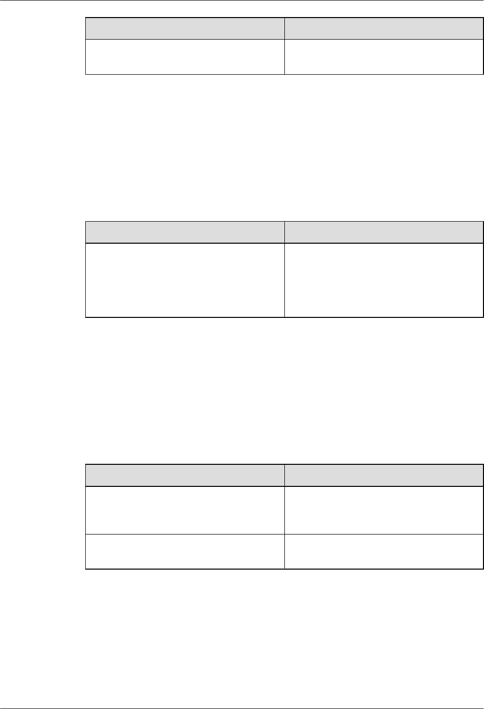
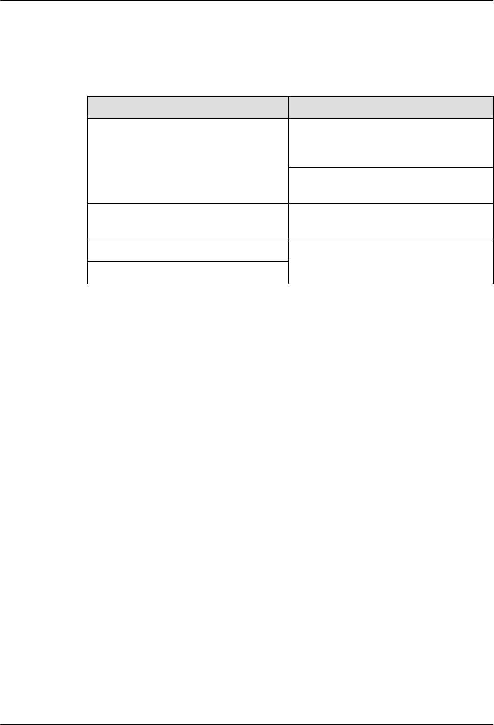
2.2 Preparing Tools and Instruments
This section describes the tools and instruments that must be prepared before the installation.
Marker
Level
Torque screwdriver
(M4 to M6)
Diagonal pliers
Power cable crimping tool RJ11 crimping tool Cable cutter
Rubber mallet T20 torque torx screwdriver Wire stripper
Hammer drill (Ø6, Ø8 and
Ø12)
Torque wrench (Ø10 mm) Protective gloves
Guarded blade utility knife ESD gloves Long measuring tape
LampSite
Installation Guide 2 Installation Preparations
Issue 08 (2015-01-15) Huawei Proprietary and Confidential
Copyright © Huawei Technologies Co., Ltd.
7
Multimeter Network cable tester Vacuum cleaner
Ladder Torque wrench for SMA
connector
Socket wrench (M6)
2.3 Requirements for Installation Personnel
This section describes requirements for installation engineers. They must be qualified and
trained, and familiar with correct operation methods and safety precautions before performing
any operations.
Before the installation, pay attention to the following items:
lTechnical engineers must take Huawei training and be familiar with proper installation and
operation methods.
lThe number of installation personnel depends on the engineering schedule and installation
environment. Generally, three to five persons are required. Generally, only three to five
onsite personnel are necessary.
LampSite
Installation Guide 2 Installation Preparations
Issue 08 (2015-01-15) Huawei Proprietary and Confidential
Copyright © Huawei Technologies Co., Ltd.
8
3 Unpacking and Checking
This section describes how to unpack and check the delivered equipment to ensure that the
materials are complete and intact.
Context
NOTE
The following lists important notes when you are transporting, lifting, or installing the equipment or
components:
lProtect them from colliding with doors, walls, shelves, or other objects.
lWear clean gloves and do not touch them with bare hands, sweat-soaked gloves, or dirty gloves.
NOTICE
You must power on the RHUB3908 or pRRU within 7 days after it is unpacked.
Procedure
Step 1 Count the total number of the shipments.
If... Then...
The total number of the components is
consistent with that recorded in the
packing lists on all packing boxes
Go to Step 2.
The total number of the components is
inconsistent with that recorded in the
packing lists on all packing boxes
Report the problems and causes to the local
Huawei office.
Step 2 Check the exterior of each packing box.
LampSite
Installation Guide 3 Unpacking and Checking
Issue 08 (2015-01-15) Huawei Proprietary and Confidential
Copyright © Huawei Technologies Co., Ltd.
9

If... Then...
The exterior of each packing box is intact Go to Step 3.
It is damaged or soaked Report the problems and causes to the local
Huawei office.
The collision label is red Do not unpack the packing box and claim for
compensation from the transportation
company.
Step 3 Check the type and quantity of the equipment in the boxes according to the packing list.
If... Then...
The type and number are consistent with
the packing list on each packing list
Sign the Packing List with the operator.
There is any shortage, wrong delivery, or
damaged equipment
Report the problems and causes to the local
Huawei office.
NOTICE
Perform the following operations to protect the components from any damages and help find
out the cause of any damage in future: 1. Store the unpacked equipment and packing materials
indoors. 2. Take photos of the storeroom, rusted or eroded equipment, packing box, and packing
materials. 3. File the photos.
----End
LampSite
Installation Guide 3 Unpacking and Checking
Issue 08 (2015-01-15) Huawei Proprietary and Confidential
Copyright © Huawei Technologies Co., Ltd.
10

4 Installing a BBU
This chapter describes the process of installing a BBU.
The BBU can have BBU3900 and BBU3910. Unless otherwise specified, the BBU refers to both
the BBU3900 and BBU3910 in this document.
For details about the installation of the BBU, see DBS3900 Installation Guide.
LampSite
Installation Guide 4 Installing a BBU
Issue 08 (2015-01-15) Huawei Proprietary and Confidential
Copyright © Huawei Technologies Co., Ltd.
11

5 Installing an RHUB3908
About This Chapter
This chapter describes the process of installing an RHUB3908.
5.1 Information About the Installation
This section describes the information to be learnt before RHUB3908 installation, including the
RHUB3908 installation scenarios, clearance, and installation environment.
5.2 Installation Process
The RHUB3908 installation involves installing an RHUB3908 module, installing RHUB3908
cables, checking the RHUB3908 hardware installation, and powering on the RHUB3908.
5.3 Installing an RHUB3908
An RHUB3908 can be installed in a cabinet, rack, shelf, or on a wall.
5.4 Installing RHUB3908 Cables
This section describes how to install cables for an RHUB3908.
5.5 Checking the RHUB3908 Hardware Installation
After an RHUB3908 is installed, check the installation of hardware including the devices and
related cables.
5.6 Power-on Check on an RHUB3908
This section describes the power-on check on the RHUB3908 after the RHUB3908 hardware is
installed and checked.
LampSite
Installation Guide 5 Installing an RHUB3908
Issue 08 (2015-01-15) Huawei Proprietary and Confidential
Copyright © Huawei Technologies Co., Ltd.
12
5.1 Information About the Installation
This section describes the information to be learnt before RHUB3908 installation, including the
RHUB3908 installation scenarios, clearance, and installation environment.
5.1.1 RHUB3908 Installation Scenarios
An RHUB3908 can be installed in a 19-inch cabinet, rack, shelf, or on a wall.
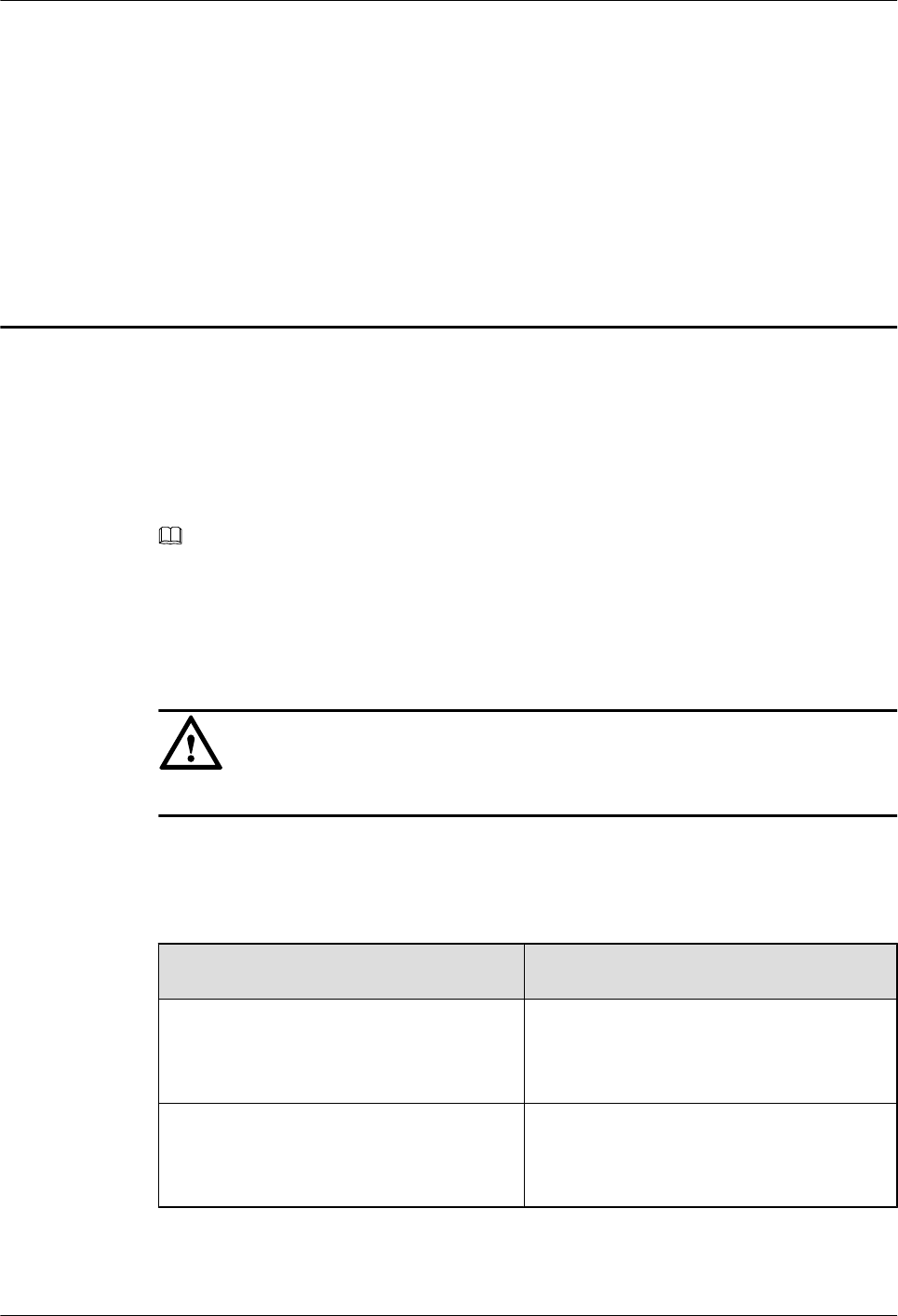
The RHUB3908 supports that mounting ears are installed in standard mode or reverse mode.
The reverse mode is used by default. The two installation modes are defined as follows:
lIn standard mode, the front of the mounting ear is aligned with the RHUB3908 panel, as
shown in Figure 5-1.
Figure 5-1 Installing mounting ears in standard mode
lIn reverse mode, the front of the mounting ear is 31 mm away from the RHUB3908 panel,
as shown in Figure 5-2.
Figure 5-2 Installing mounting ears in reverse mode
LampSite
Installation Guide 5 Installing an RHUB3908
Issue 08 (2015-01-15) Huawei Proprietary and Confidential
Copyright © Huawei Technologies Co., Ltd.
13
Installing an RHUB3908 in a 19-Inch Cabinet or Rack
Installing an RHUB3908 in a 19-inch cabinet or rack: Secure the mounting ear to the mounting
bracket by using M6 screws.
lIf there is no other modules installed in the 1 U space near the RHUB3908, install the
RHUB3908 directly. Otherwise, remove the modules before installing the RHUB3908.
lBefore installation, you need to check the installation mode supported by the rack and adjust
the position of the mounting ear.
Figure 5-3 and Figure 5-4 show RHUB3908s installed in a cabinet or rack, respectively.
Figure 5-3 Installing an RHUB3908 in a 19-inch cabinet or rack in standard mode
Figure 5-4 Installing an RHUB3908 in a 19-inch cabinet in reverse mode
Installing an RHUB3908 in a 19-Inch Shelf
When an RHUB3908 is installed in a 19-inch shelf, the shelf must be installed on a wall. One
shelf can house multiple RHUB3908s with 1 U space between two RHUB3908s.
LampSite
Installation Guide 5 Installing an RHUB3908
Issue 08 (2015-01-15) Huawei Proprietary and Confidential
Copyright © Huawei Technologies Co., Ltd.
14
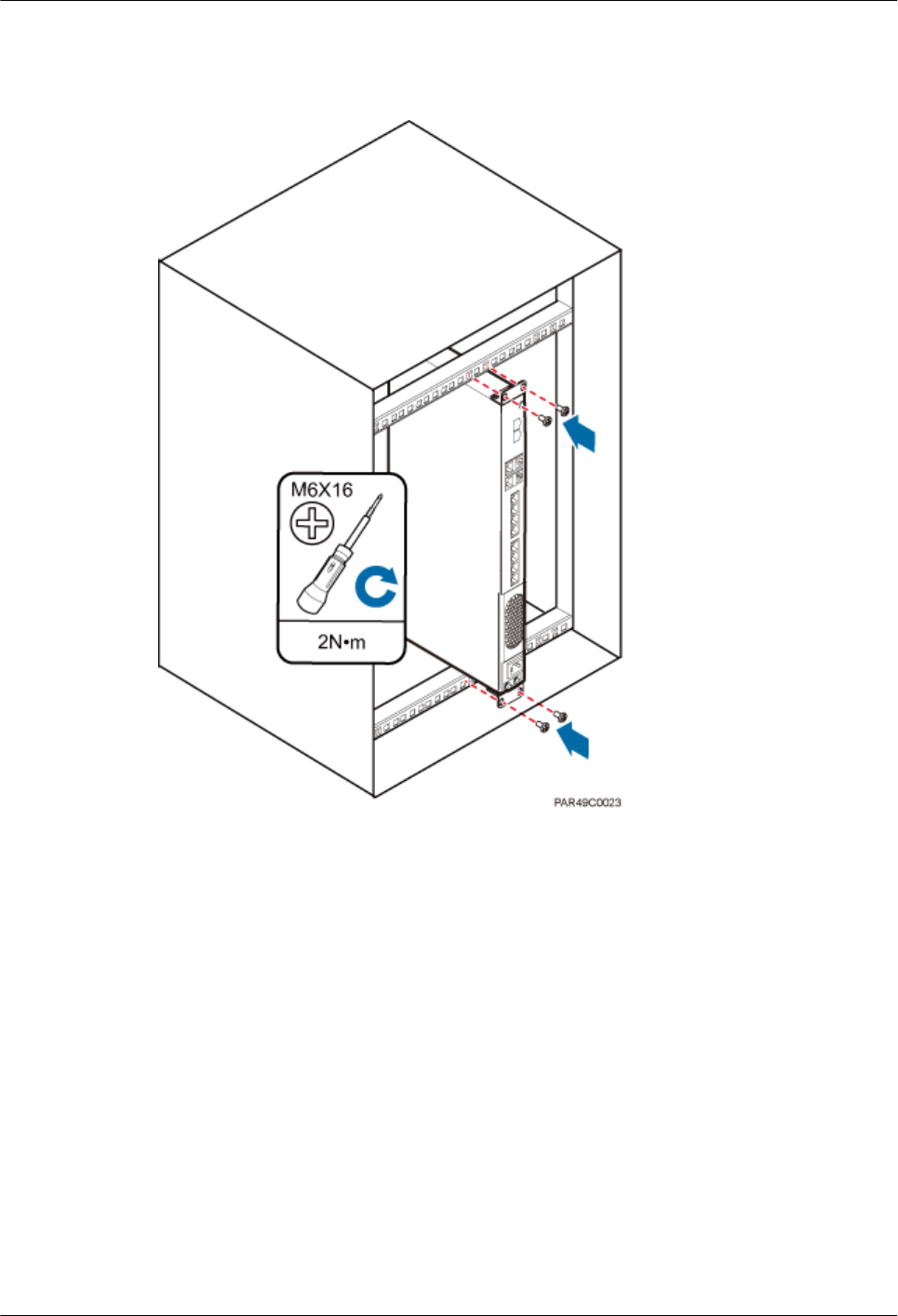
Figure 5-5 and Figure 5-6 show RHUB3908s installed in a 19-inch shelf.
Figure 5-5 RHUB3908 installed in a 19-inch shelf in standard mode
LampSite
Installation Guide 5 Installing an RHUB3908
Issue 08 (2015-01-15) Huawei Proprietary and Confidential
Copyright © Huawei Technologies Co., Ltd.
15
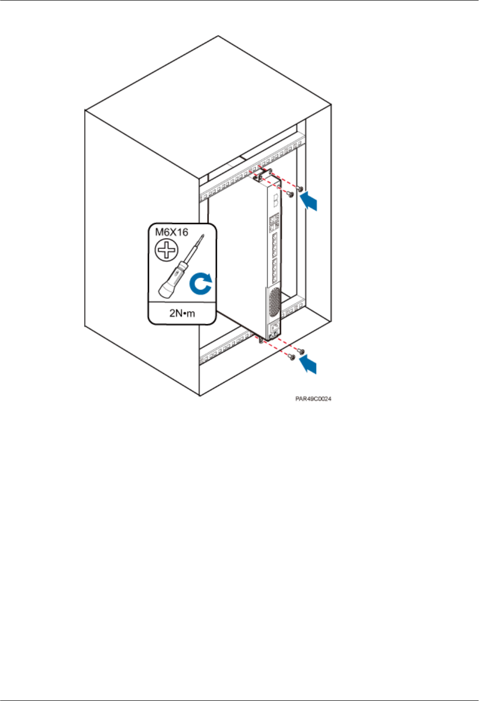
Figure 5-6 RHUB3908 installed in a 19-inch shelf in reverse mode
Installing an RHUB3908 on a Wall
An RHUB3908 can be installed on a wall.
The wall on which an RHUB3908 is installed must meet the following requirements:
lWhen a single RHUB3908 is installed, the wall must have a capacity of bearing at least
four times the weight of the RHUB3908.
lExpansion bolts must be tightened to 10 N·m (88.507 bf·in.) to ensure the bolts work
properly and the wall remains intact without cracks in it.
Figure 5-7 shows an RHUB3908 installed on a wall.
LampSite
Installation Guide 5 Installing an RHUB3908
Issue 08 (2015-01-15) Huawei Proprietary and Confidential
Copyright © Huawei Technologies Co., Ltd.
16
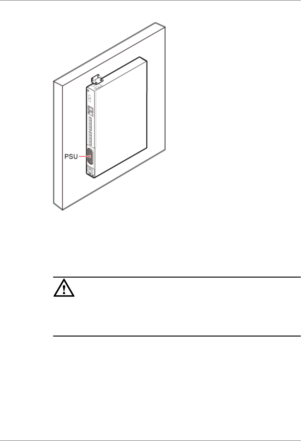
Figure 5-7 RHUB3908 installed on a wall
5.1.2 Installation Clearance Requirements of an RHUB3908
When an RHUB3908 is installed in a 19-inch cabinet, rack, shelf, or on a wall, a minimum
clearance is required for easy cabling and operation and maintenance. A recommended
installation clearance is provided based on experience.
NOTICE
lDo not install or place inflammable materials above or under an RHUB3908.
lA clearance of 350 mm must be reserved in front of the air intake vent of the fan of the power
supply unit (PSU) for maintenance.
Figure 5-8 shows the installation clearance for the RHUB3908 installed in a 19-inch cabinet,
rack, or shelf.
LampSite
Installation Guide 5 Installing an RHUB3908
Issue 08 (2015-01-15) Huawei Proprietary and Confidential
Copyright © Huawei Technologies Co., Ltd.
17
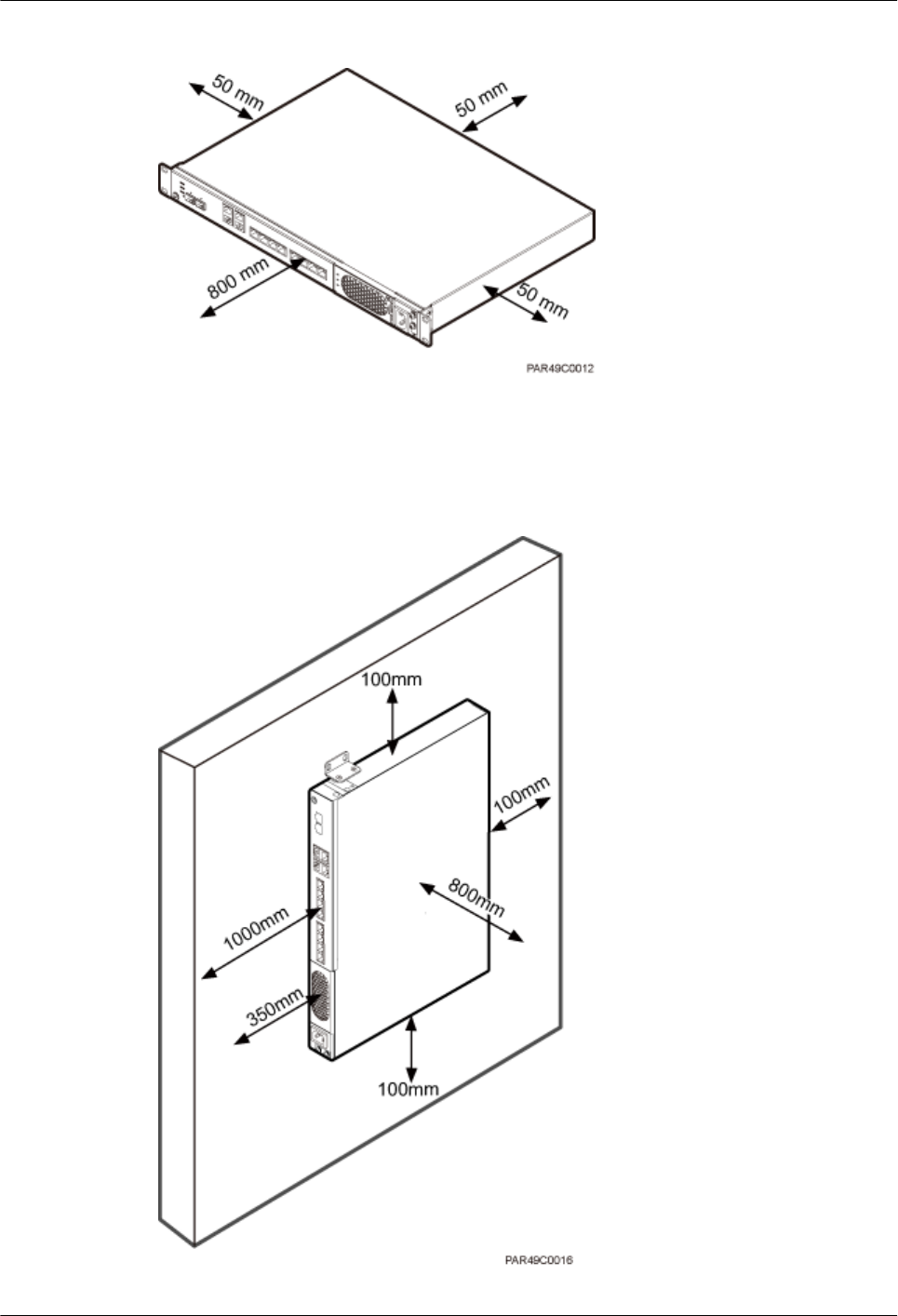
Figure 5-8 Installation clearance for an RHUB3908 installed in a 19-inch cabinet, rack, or shelf
Figure 5-9 and Figure 5-10 shows the recommended and minimum installation clearance
respectively when the RHUB3908 is installed on a wall.
Figure 5-9 Recommended installation clearance for a wall-mounted RHUB3908 (unit: mm)
LampSite
Installation Guide 5 Installing an RHUB3908
Issue 08 (2015-01-15) Huawei Proprietary and Confidential
Copyright © Huawei Technologies Co., Ltd.
18
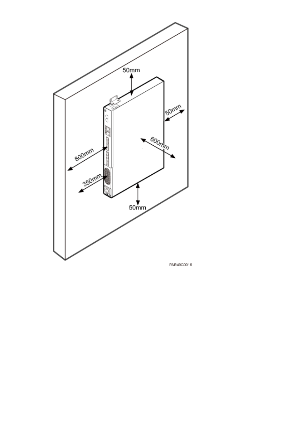
Figure 5-10 Minimum installation clearance for a wall-mounted RHUB3908 (unit: mm)
5.1.3 Installation Environment of an RHUB3908
The installation environment of an RHUB3908 involves the running environment specifications
for the RHUB3908 and other specifications.
RHUB3908 Running Environment Specifications
Table 5-1 shows the environment specifications for the RHUB3908 installed indoors.
lThe temperature and humidity of the installation position must ensure normal operation. A
cool and ventilated place is recommended.
lThe heat dissipation holes on the RHUB3908 cannot be blocked.
LampSite
Installation Guide 5 Installing an RHUB3908
Issue 08 (2015-01-15) Huawei Proprietary and Confidential
Copyright © Huawei Technologies Co., Ltd.
19

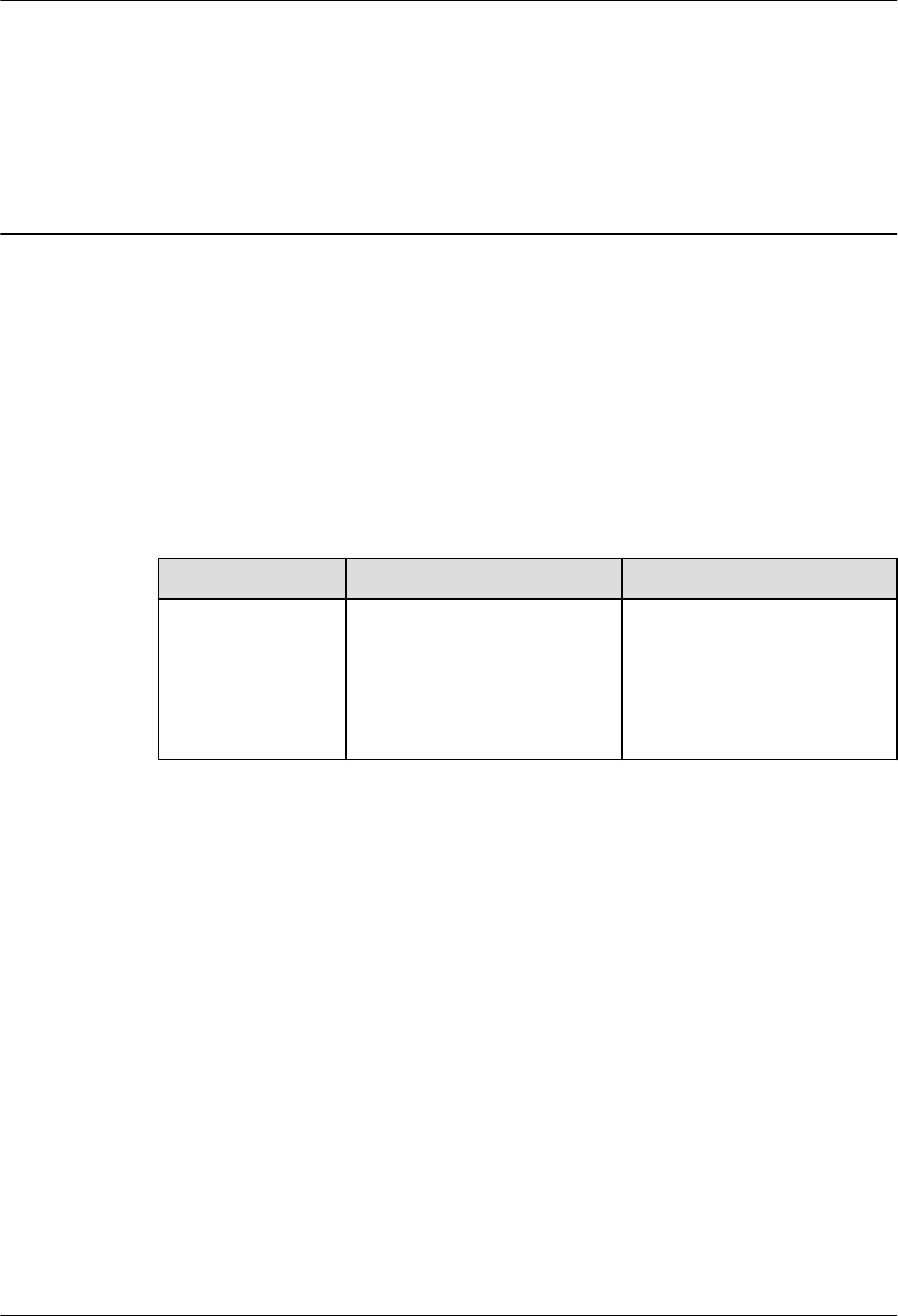
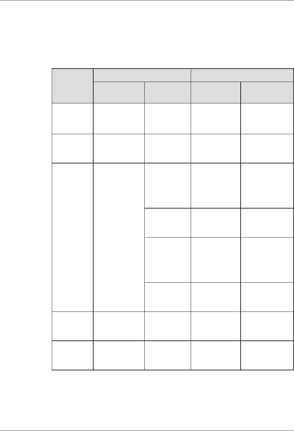
Table 5-1 RHUB3908 environment specifications
Specifi
cations
Installation
Scenario
RHUB3908
Quantity
Condition Remarks
Operati
ng
tempera
ture
Installed on a
wall or in a 19-
inch rack.
N/A -5°C to +50°
C
N/A
Installed in a
shelf.
1 -5°C to +45°
C
N/A
2 -5°C to +43°
C
N/A
3 -5°C to +40°
C
N/A
Relativ
e
humidit
y
Installed in all
scenarios.
N/A 5% RH to
95% RH
N/A
Altitude N/A N/A -60 m to
+1800 m
Works properly.
1800 m to
4000 m
Above the 1800 m altitude,
the maximum operating
temperature decreases by 1°C
each time the altitude
increases by 220 m.
NOTE
Installing more than one RHUB3908, 1 U space is required between two RHUB3908s.
Other Running Environment Specifications
lThe RHUB3908 cannot be installed at an air outlet of the heat dissipation box of an air
conditioner or other heat-generating appliances.
lThe RHUB3908 cannot be installed near a strong heat source.
lThe RHUB3908 cannot be installed in a position with water dripping, such as outdoor
equipment of air conditioners, pipe, and leaking or dripping roofs.
lThe installation position must be far from rains. If the RHUB3908 is installed on a wall,
there must be no window on either side of the wall.
lThe installation position must be far away from high voltage, highly corrosive devices,
flammable or explosive substances, and electromagnetic interference.
lThe RHUB3908 must be installed in a dry, ventilating, and dust-proof place.
lIf the RHUB3908 is installed in parking areas or basements, the installation position must
be well-ventilated.
LampSite
Installation Guide 5 Installing an RHUB3908
Issue 08 (2015-01-15) Huawei Proprietary and Confidential
Copyright © Huawei Technologies Co., Ltd.
20
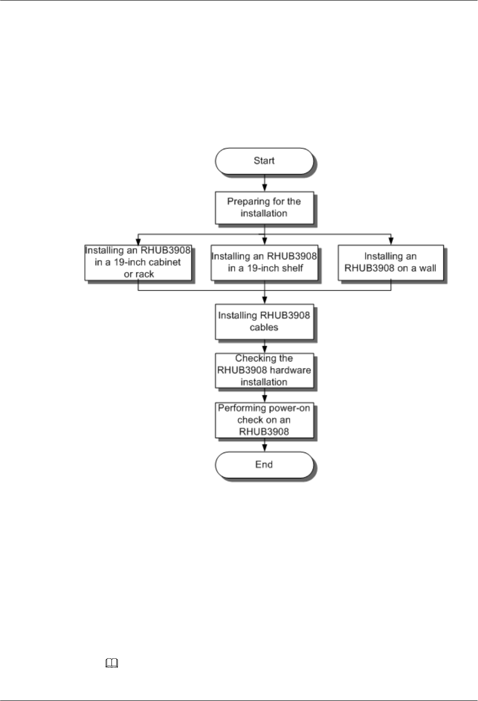
5.2 Installation Process
The RHUB3908 installation involves installing an RHUB3908 module, installing RHUB3908
cables, checking the RHUB3908 hardware installation, and powering on the RHUB3908.
Figure 5-11 shows the RHUB3908 installation process.
Figure 5-11 RHUB3908 installation process
5.3 Installing an RHUB3908
An RHUB3908 can be installed in a cabinet, rack, shelf, or on a wall.
5.3.1 Installing an RHUB3908 in a 19-Inch Cabinet or Rack
This section describes how to install an RHUB3908 in a 19-inch cabinet.
Procedure
lThe following describes how to install an RHUB3908 with mounting ears in reverse mode:
NOTE
If necessary, request one more person for assistance.
LampSite
Installation Guide 5 Installing an RHUB3908
Issue 08 (2015-01-15) Huawei Proprietary and Confidential
Copyright © Huawei Technologies Co., Ltd.
21
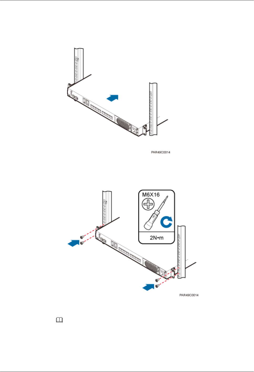
1. With one hand holding it, align the mounting holes with the installation holes, slowly
push the RHUB3908 into the required position in the cabinet, as shown in Figure
5-12.
Figure 5-12 Pushing an RHUB3908 into a cabinet
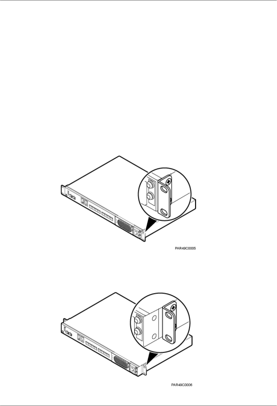
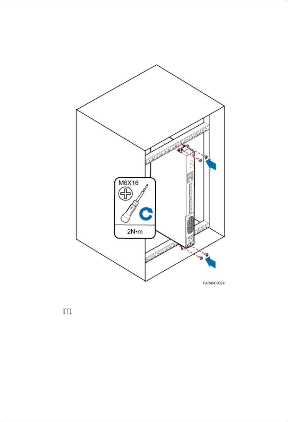
2. Use a torque screwdriver or Phillips screwdriver to tighten the four M6×16 screws
with a torque of 2 N•m, as shown in Figure 5-13.
Figure 5-13 Tightening screws
lThe following describes how to install an RHUB3908 with mounting ears aligned with the
RHUB3908 panel:
NOTE
If necessary, request one more person for assistance.
1. Remove the mounting ears on both sides of the RHUB3908 by removing the four
M4×8 screws, as shown in Figure 5-14.
LampSite
Installation Guide 5 Installing an RHUB3908
Issue 08 (2015-01-15) Huawei Proprietary and Confidential
Copyright © Huawei Technologies Co., Ltd.
22
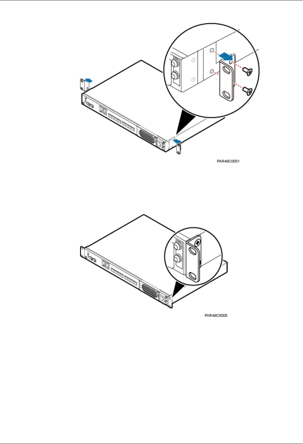
Figure 5-14 Removing mounting ears and screws
2. Use a torque screwdriver or Phillips screwdriver to tighten the four M4×8 screws with
a torque of 1.4 N•m to install the removed mounting ears again, as shown in Figure
5-15. The mounting ears must be aligned with the RHUB3908 panel.
Figure 5-15 Installing mounting ears in standard mode
3. With one hand holding it, align the mounting holes with the installation holes, slowly
push the RHUB3908 into the required position in the cabinet, as shown in Figure
5-16.
LampSite
Installation Guide 5 Installing an RHUB3908
Issue 08 (2015-01-15) Huawei Proprietary and Confidential
Copyright © Huawei Technologies Co., Ltd.
23
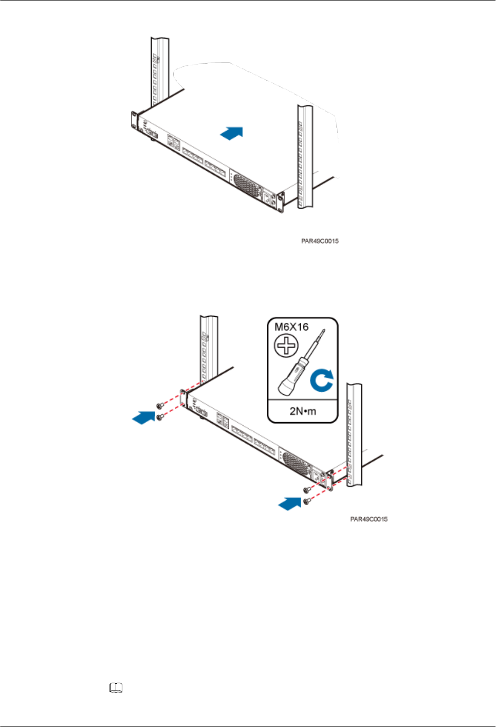
Figure 5-16 Pushing an RHUB3908 into a cabinet
4. Use a torque screwdriver or Phillips screwdriver to tighten the four M6×16 screws
with a torque of 2 N•m, as shown in Figure 5-17.
Figure 5-17 Tightening screws
----End
5.3.2 Installing an RHUB3908 in a 19-Inch Shelf
If a shelf houses more than one RHUB3908, 1 U space is required between two RHUB3908s.
The PSU must be installed at the bottom of the cabinet.
Procedure
lThe following describes how to install an RHUB3908 with mounting ears installed in
reverse mode:
NOTE
If necessary, request one more person for assistance.
LampSite
Installation Guide 5 Installing an RHUB3908
Issue 08 (2015-01-15) Huawei Proprietary and Confidential
Copyright © Huawei Technologies Co., Ltd.
24
1. With one hand holding it, align the mounting holes with the installation holes, slowly
push the RHUB3908 into the required position in the shelf.
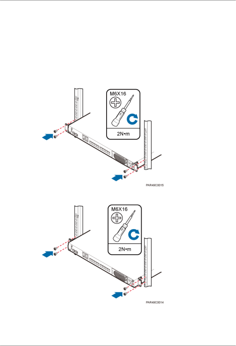
2. Use a torque screwdriver or Phillips screwdriver to tighten the four M6×16 screws
with a torque of 2 N•m, as shown in Figure 5-18.
Figure 5-18 Tightening screws
lThe following describes how to install an RHUB3908 with mounting ears installed in
standard mode:
NOTE
If necessary, request one more person for assistance.
1. Remove the mounting ears on both sides of the RHUB by removing the four M4×8
screws, as shown in Figure 5-19.
LampSite
Installation Guide 5 Installing an RHUB3908
Issue 08 (2015-01-15) Huawei Proprietary and Confidential
Copyright © Huawei Technologies Co., Ltd.
25

Figure 5-19 Removing mounting ears and screws
2. Use a torque screwdriver or Phillips screwdriver to tighten the four M4×8 screws with
a torque of 1.4 N•m to install the removed mounting ears again, as shown in Figure
5-20. The mounting ears must be aligned with the RHUB panel.
Figure 5-20 Installing mounting ears in standard mode
3. With one hand holding it, align the mounting holes with the installation holes, slowly
push the RHUB3908 into the required position in the cabinet, as shown in .
4. Use a torque screwdriver or Phillips screwdriver to tighten the four M6×16 screws
with a torque of 2 N•m, as shown in Figure 5-21.
LampSite
Installation Guide 5 Installing an RHUB3908
Issue 08 (2015-01-15) Huawei Proprietary and Confidential
Copyright © Huawei Technologies Co., Ltd.
26
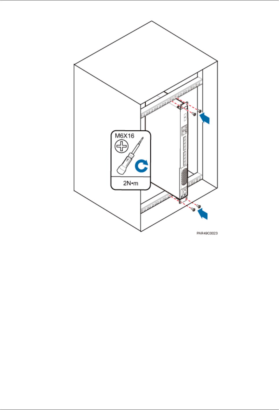
Figure 5-21 Tightening screws
----End
5.3.3 Installing an RHUB3908 on a Wall
An RHUB3908 can be installed on a wall.
Procedure
Step 1 The mounting ears are installed in reverse mode by default. Before installing an RHUB3908 on
a wall, modify the installation mode of the mounting ears on the RHUB3908.
lUse a torque screwdriver or Phillips screwdriver to remove the mounting ears on both sides
of the RHUB3908 by removing the four M4×8 screws, as shown in Figure 5-22.
LampSite
Installation Guide 5 Installing an RHUB3908
Issue 08 (2015-01-15) Huawei Proprietary and Confidential
Copyright © Huawei Technologies Co., Ltd.
27
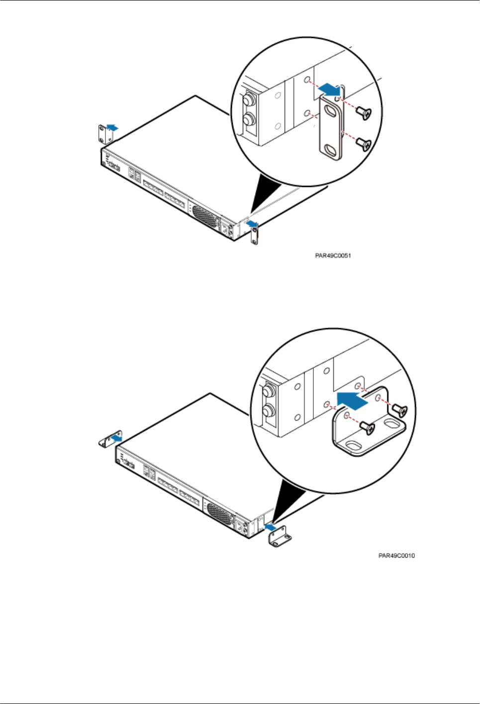
Figure 5-22 Removing screws and mounting ears
lRotate the mounting ears 90 degrees clockwise, and use a torque screwdriver or Phillips
screwdriver to secure the mounting ear with a torque of 1.4 N•m, as shown in Figure 5-23.
Figure 5-23 Installing mounting ears and screws
Step 2 Determine the position on the wall for installing the RHUB3908 based on the requirements in
the engineering blueprint and Installation Clearance Requirements of an RHUB. Place the
RHUB3908 to the position to be installed against the wall, and then mark the four anchor points
where the mounting ear screws are fastened using a marker, as shown in Figure 5-24.
LampSite
Installation Guide 5 Installing an RHUB3908
Issue 08 (2015-01-15) Huawei Proprietary and Confidential
Copyright © Huawei Technologies Co., Ltd.
28
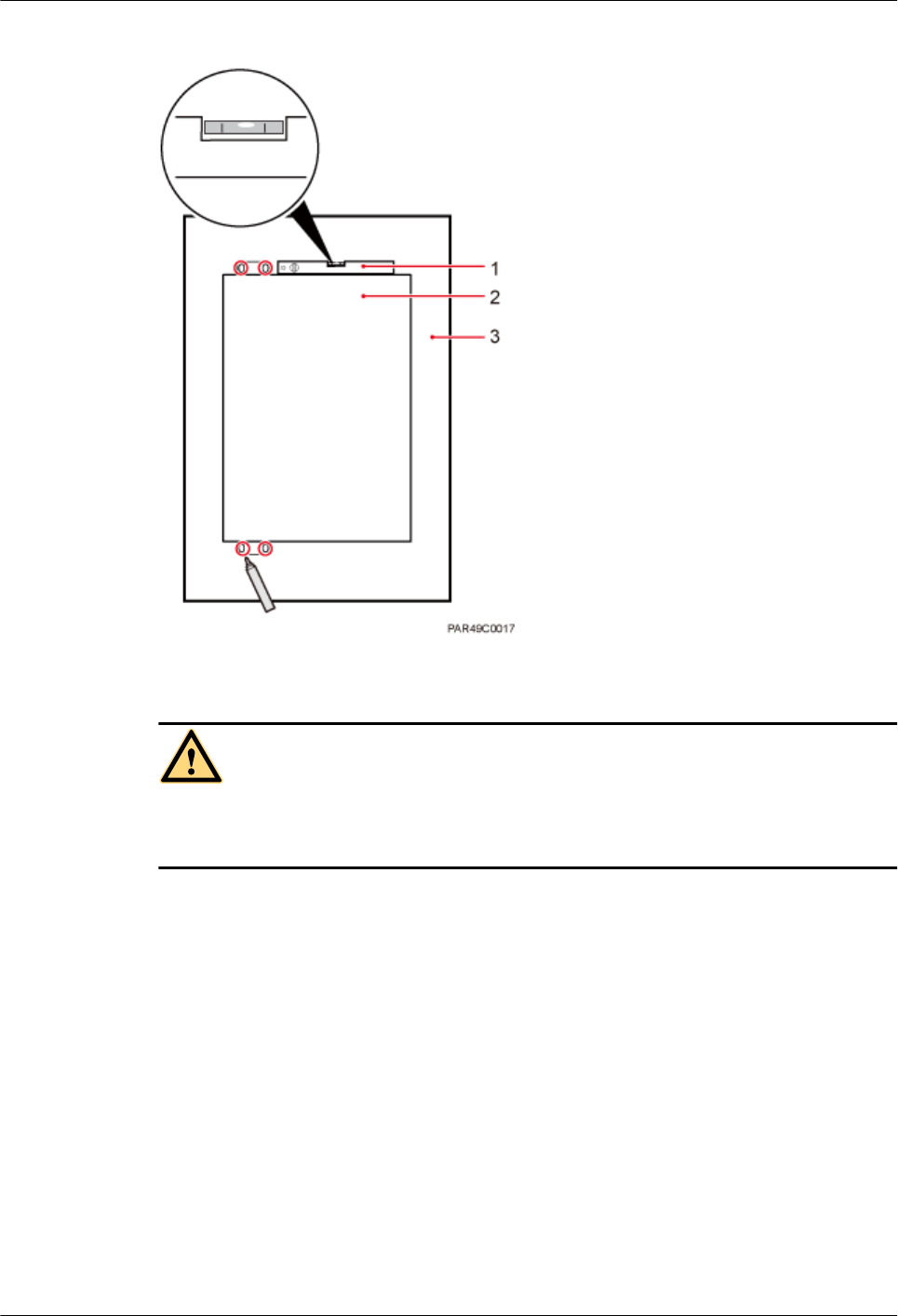
Figure 5-24 Anchor points for installing an RHUB3908 on a wall
(1) Level (2) RHUB3908 (3) Wall
CAUTION
To prevent inhalation or eye contact with dust, take adequate preventive measures when drilling
holes.
Step 3 Drill holes at the anchor point and install expansion bolts, as shown in Figure 5-25.
LampSite
Installation Guide 5 Installing an RHUB3908
Issue 08 (2015-01-15) Huawei Proprietary and Confidential
Copyright © Huawei Technologies Co., Ltd.
29
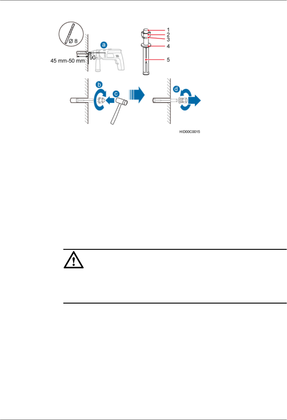
Figure 5-25 Drilling holes and installing expansion bolts
(1) M6×60
expansion bolt
(2) Nut (3) Spring washer (4) Flat washer (5) Extension tub
1. Use a hammer drill with bit 8 to drill holes with a diameter of 8 mm and a depth of 45 mm
to 50 mm at the marked anchor points. All the holes have the same depth.
2. Use a vacuum cleaner to clear the dust inside and around each hole. If the distance between
two holes is incorrect, mark and drill holes again.
3. Partially tighten an expansion bolt and place it vertically into each hole.
4. Use a rubber mallet to hit the expansion bolt until the entire expansion sleeve is in the hole.
5. Remove the M6×60 bolt, nut, spring washer, and flat washer from each expansion bolt in
sequence.
NOTICE
After removing an expansion bolt, ensure that the top of the expansion sleeve is level with
the wall. If it is not level, the RHUB3908 cannot be installed on the concrete floor evenly
and securely.
Step 4 Align the mounting holes with the four M6×60 expansion bolts. Install spring washer 6 and flat
washer 6 in sequence on each M6×60 expansion bolt, insert the bolts to each expansion tub, and
then use a torque wrench or socket wrench to tighten the four M6×60 bolts with a torque of 5
N•m to secure the RHUB3908 to the wall, as shown in Figure 5-26.
LampSite
Installation Guide 5 Installing an RHUB3908
Issue 08 (2015-01-15) Huawei Proprietary and Confidential
Copyright © Huawei Technologies Co., Ltd.
30
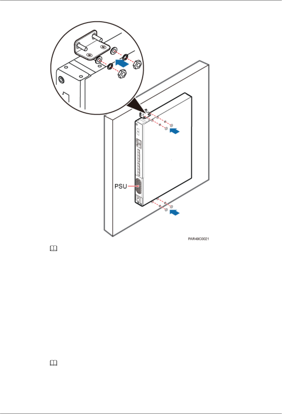
Figure 5-26 Installing an RHUB3908 on a wall
NOTE
As shown in the preceding figure, when the RHUB3908 is placed against the wall, ensure that the
RHUB3908 panel is vertical to the ground and the PSU is on the lower part of the RHUB3908 panel.
----End
5.4 Installing RHUB3908 Cables
This section describes how to install cables for an RHUB3908.
5.4.1 Requirements for Cable Layout
Cables must be routed according to the specified cabling requirements to prevent signal
interference.
NOTE
If a cable listed below is not required, skip the requirements for routing the cable.
General Requirements for Cable Layout
中国标准
LampSite
Installation Guide 5 Installing an RHUB3908
Issue 08 (2015-01-15) Huawei Proprietary and Confidential
Copyright © Huawei Technologies Co., Ltd.
31

l综合布线系统工程设计规范 GB 50311-2007
l综合布线工程验收规范(含条文说明) GB 50312-2007
l安全防范工程技术规范 GB 50348-2004
l电子信息系统机房施工及验收规范 GB 50462-2008
l智能建筑工程质量验收规范 GB 50339-2003
l建筑电气工程施工质量验收规范 GB 50303-2002
l通信管道工程施工及验收技术规范 GB 50374-2006
国际标准
l用户建筑综合布 ISO/IEC 11801
l商业建筑电信布线标准 EIA/TIA 568
l商业建筑电信布线安装标准 EIA/TIA 569
l商业建筑通信基础结构管理规范 EIA/TIA 606
l商业建筑通信接地要求 EIA/TIA 60
l信息系统通用布线标准 EN 50173
l信息系统布线安装标准 EN 50174
Bending radius
lThe bending radius of a power cable or a protection ground (PGND) cable is at least three
times the diameter of the cable.
lThe bending radius of an optical cable is at least 20 times the diameter of the optical cable,
and the minimum bending radius of the branch at each end of the optical cable is 30 mm.
lThe bending radius of the signal cable must be at least five times the diameter of the cable.
Cable Binding
lCables of the same type are bound together.
lDifferent types of cables must be separately routed with a minimum spacing of 30 mm and
cannot be entangled or crossed.
lThe cables are bound tightly and neatly and the cable sheath is intact.
lThe cable ties face the same direction and all cable ties bound at similar positions must be
in a straight line.
lThe extra length of each indoor cable tie must be cut off. A slack of 5 mm is reserved for
each outdoor cable tie. All cut surfaces have no sharp edges.
lLabels or nameplates are attached to both ends, joints, or turns of cables after they are
installed.
Safety
l穿管/线槽采用钢管或阻燃聚氯乙烯硬质管,线槽的截面利用率应为30%~50%,
穿管的截面利用率应为25%~30%。
lCables are placed away from sharp objects or wall burrs. If these positions are inevitable,
protection pipes are required for the cables.
lCables are routed away from heat sources, or heat-insulation materials are added between
cables and heat sources.
lCables are routed away the cooling vents of the RHUB3908.
LampSite
Installation Guide 5 Installing an RHUB3908
Issue 08 (2015-01-15) Huawei Proprietary and Confidential
Copyright © Huawei Technologies Co., Ltd.
32

lA clearance is reserved at turns of a cable or the position close to a device, facilitating cable
and device maintenance. The recommended clearance is about 0.1 m.
Requirements for Special Cables
Ethernet Cable
lA maximum of 100 Ethernet cables can be bundled if no PVC pipes are used. If pipes are
used, a maximum of 24 Ethernet cables can be led through a pipe. In this case, ensure that
1/3 space inside the pipes must be vacant.
Power cable
lPositions for routing power cables meet requirements of the engineering design.
lCables are routed only by qualified and trained personnel before all preparations are made.
lCables are routed in an untangled and orderly fashion.
PGND cable
lPGND cables are buried in the ground or routed indoors. They cannot be routed overhead
before they are routed into the equipment room.
lOuter conductors of coaxial cables and both ends of the shield layers on shielded cables
are in proper electrical contact with the metal surface of the equipment to which they are
connected.
lPGND cables and signal cables are installed in an untangled and orderly fashion. A certain
distance is reserved between them to prevent interference from each other.
lFuses or switches are not allowed on PGND cables.
lOther devices cannot be used for electrical connections of PGND cables.
lAll the metal parts in the equipment are reliably connected to the ground terminal.
Optical cable
lCables are routed in an untangled and orderly fashion.
lOptical fibers cannot be bound at turns.
lOptical fibers cannot be stretched with too much force or stepped on, and they are far away
from sharp objects. Heavy objects cannot be placed on optical cables.
lWhen optical cables are routed, the extra length of the cables is coiled around special
devices, such as a fiber coiler.
lEven strength is applied when optical cables are coiled and optical cables cannot be bent
in a forcible manner.
lVacant optical connectors are covered with dust-proof caps.
lFiber optic cables cannot be squeezed by the cabinet door when routed through the cabinet.
lIf optical cables need to be routed on the tower platform, the optical cables are routed along
the inner side of the guard rail and the distance between the guard rail and the cable is the
shortest one.
lIf optical cables need to be routed close to a device on the tower, the optical cables are
secured to the guard rail or pole with cable clips and the device cannot be far away from
the position for securing the optical cables.
lIf the optical cable close to a device on the tower is too long, the optical cables are wrapped
and secured to the tower.
LampSite
Installation Guide 5 Installing an RHUB3908
Issue 08 (2015-01-15) Huawei Proprietary and Confidential
Copyright © Huawei Technologies Co., Ltd.
33
5.4.2 RHUB3908 Cable List
This section describes the connector types and connections of the RHUB3908 cables.
Table 5-2 lists RHUB3908 cables.
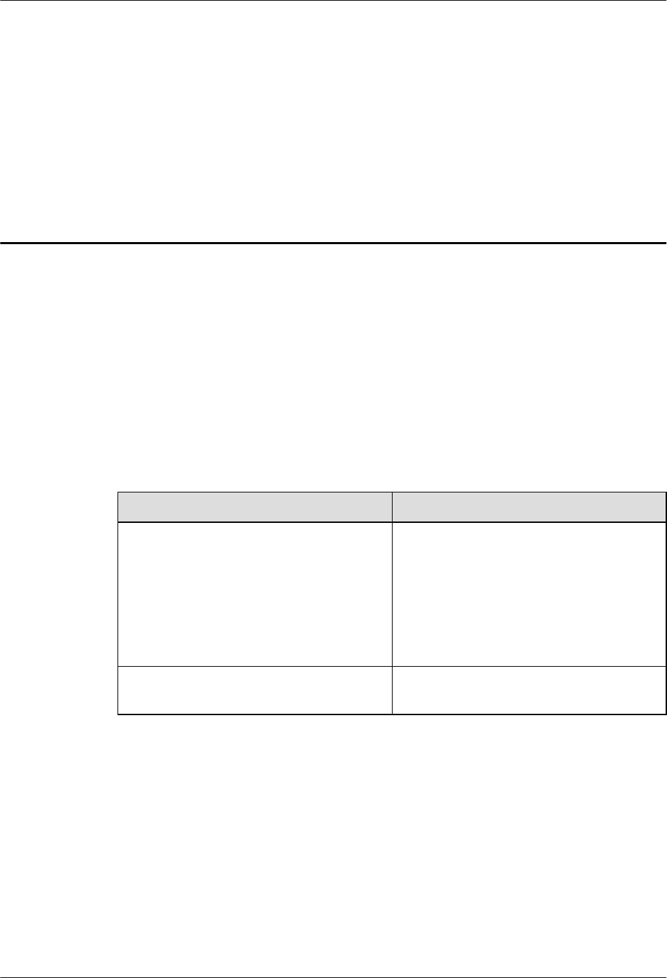
Table 5-2 RHUB3908 cable list
Cable One End The Other End
Connector Connected
to...
Connector Connected to...
PGND cable OT terminal (M4,
6 mm2 [0.009 in.
2])
Ground screws
on the
RHUB3908
OT terminal
(M6, 6 mm2
[0.009 in.2])
Ground terminal
on the external
ground bar
RHUB3908
Power
Supply Cable
C13 female
connector
AC power
input socket on
the RHUB3908
3-pin connector External power
input socket
CPRI Optical
Fiber
DLC connector CPRI port on
the LBBP,
WBBP or
UBBP in the
BBU
DLC connector CPRI0 or CPRI1
port on the
RHUB3908
CPRI0 or
CPRI1 port on
the RHUB3908
DLC connector CPRI0 or CPRI1
port on the
RHUB3908
CPRI port on
the LBBP,
WBBP or
UBBP in the
BBU
FC connector,
SC connector, or
LC connector
ODF
CPRI0 or
CPRI1 port on
the RHUB3908
FC connector,
SC connector, or
LC connector
ODF
Ethernet
Cable
RJ45 connector CPRI_E0~CP
RI_E7 port on
the RHUB3908
RJ45 connector CPRI_E0~CPRI_
E1 port on the
pRRU3901
(Optional)
RHUB3908
Alarm Cable
RJ45 connector EXT_ALM
port on the
RHUB3908
Bare end Alarm signal port
of the monitored
equipment
LampSite
Installation Guide 5 Installing an RHUB3908
Issue 08 (2015-01-15) Huawei Proprietary and Confidential
Copyright © Huawei Technologies Co., Ltd.
34
NOTE
lIf one end of the CPRI cable is connected to the DLC connector, the other end connects the BBU, or
RHUB3908 through the DLC connector. If one end of the CPRI cable is connected to the ODF adapter,
the other end connects the BBU or RHUB3908 through a connector corresponding to the adapter. The
connectors include the FC connector, SC connector, and LC connector.
lThe Extender can be used to lengthen the distance between the RHUB3908 and the pRRU3901
connected using the Ethernet cable. If the Extender is used, the Ethernet cable is divided into two parts,
one between the RHUB3908 and the Extender and the other between the Extender and the pRRU3901.
5.4.3 Cable Connections
This section describes the cable connections for an RHUB3908.
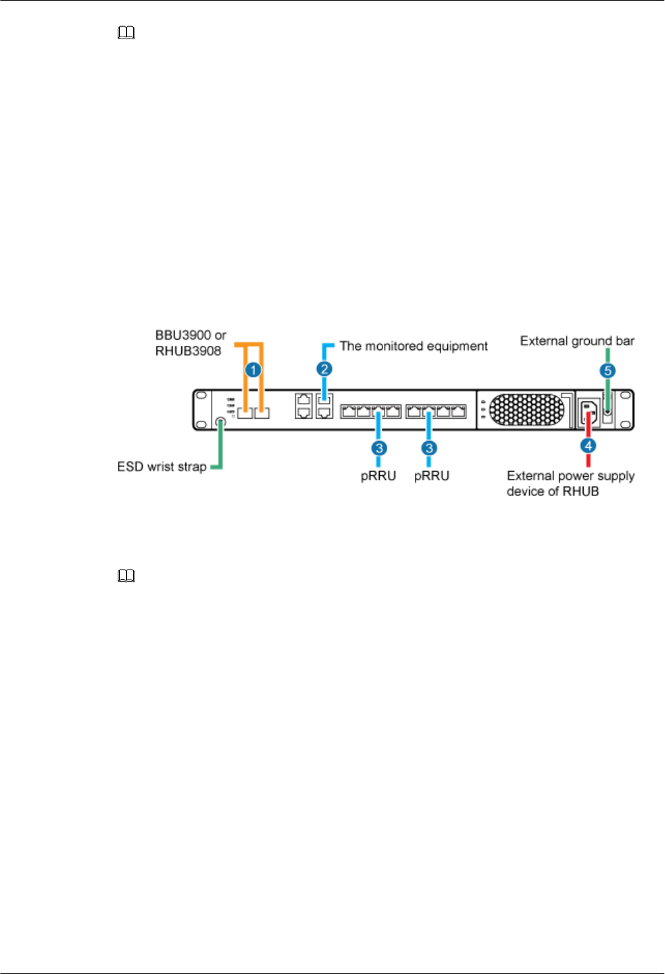
Figure 5-27 shows the cable connections for an RHUB3908. The port of GE0, GE1 and ETH
are reserved.
Figure 5-27 Cable connections for an RHUB3908
(1) CPRI optical cable (2) RHUB3908 alarm cable (3) Ethernet cable
(4) RHUB3908 power cable (5) PGND cable -
NOTE
The Extender can be used to lengthen the distance between the RHUB3908 and the pRRU3901 connected
using the Ethernet cable. If the Extender is used, the Ethernet cable is divided into two parts, one between
the RHUB3908 and the Extender and the other between the Extender and the pRRU3901.
5.4.4 RHUB3908 Cable Installation Process
This section describes the process of installing RHUB3908 cables.
Figure 5-28 shows the RHUB3908 cable installation process.
LampSite
Installation Guide 5 Installing an RHUB3908
Issue 08 (2015-01-15) Huawei Proprietary and Confidential
Copyright © Huawei Technologies Co., Ltd.
35
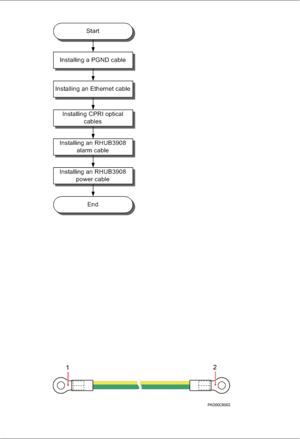
Figure 5-28 RHUB3908 cable installation process
5.4.5 Installing an RHUB3908 PGND Cable
An RHUB3908 PGND cable ensures proper grounding of an RHUB3908.
Prerequisites
The OT terminals at both ends of the PGND cable are prepared.
Context
The yellow and green or green PGND cable is a single cable. The cross-sectional area of the
PGND cable is 6 mm2 (0.009 in.2). Both ends of the cable are OT terminals, as shown in Figure
1.
Figure 5-29 Exterior of a PGND cable
(1) OT terminal (6 mm2 [0.009 in.2], M4) (2) OT terminal (6 mm2 [0.009 in.2], M6)
LampSite
Installation Guide 5 Installing an RHUB3908
Issue 08 (2015-01-15) Huawei Proprietary and Confidential
Copyright © Huawei Technologies Co., Ltd.
36
NOTE
lIf the PGND cable is provided by the customer, a copper-core cable with a minimum cross-sectional
area of 6 mm2 (0.009 in.2) or 10 AWG is recommended.
lThe OT terminals at both ends of the PGND cable are assembled at the site.
lThe M6 OT terminal has the default size. You can replace it with another OT terminal of the expected
size based on the site requirement.
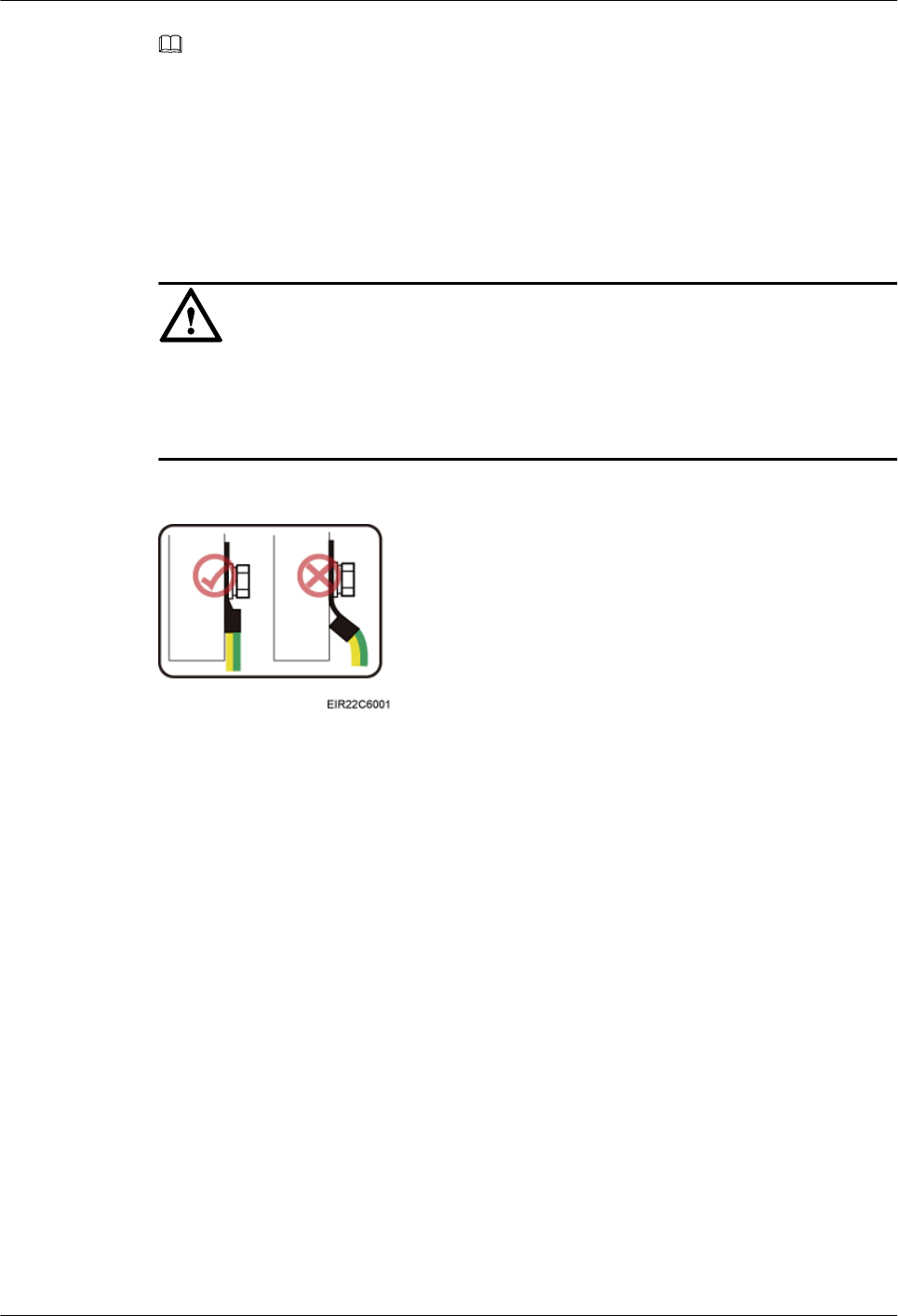
NOTICE
lEnsure proper grounding of the RHUB3908 using a PGND cable.
lWhen installing the PGND cable, tightly press the OT terminal in the correct direction, as
shown in Figure 5-30.
Figure 5-30 Correct direction of an OT terminal for the PGND cable
Procedure
Step 1 Route the PGND cable by referring to Requirements for Cable Layout.
Step 2 Use a torque screwdriver or Phillips screwdriver to secure the M4 OT terminal at one end of the
PGND cable to the ground screw on the RHUB3908 panel with a torque of 1.4 N•m. If the OT
terminal is a one-hole OT terminal, connect it to the ground screw on the lower part of the
RHUB3908 panel, as shown in Figure 5-31.
LampSite
Installation Guide 5 Installing an RHUB3908
Issue 08 (2015-01-15) Huawei Proprietary and Confidential
Copyright © Huawei Technologies Co., Ltd.
37
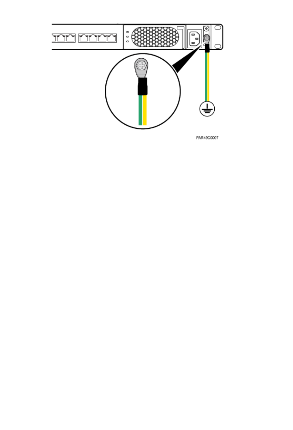
Figure 5-31 Installing an RHUB3908 PGND cable
Step 3 Use a torque screwdriver or Phillips screwdriver to secure the M8 OT terminal at one end of the
PGND cable to the wiring terminal on the ground bar at the site with a torque of 1.4 N•m.
----End
Follow-up Procedure
1. Route the cable, and then use a cable tie to bind the cable. For details, see Requirements
for Cable Layout.
2. Label the installed cable. For details, see section 8.3 Attaching an L-Shaped Label.
5.4.6 Installing an Ethernet Cable
This section describes how to install an Ethernet cable. A pRRU3901 can have two transmission
ports or three transmission ports, requiring the same installation operations. This section uses
the pRRU3901 with three transmission ports as an example.
Prerequisites
lEthernet cables are not delivered, and they must be prepared onsite. You need to use a
network cable tester to test the Ethernet cable connection.
lThe Ethernet cable must be of Category 5e (enhanced) or higher. In addition, its cross-
sectional area must be 24 AWG or larger and frame spread rating must be CM or higher.
With the internal PoE module providing power, the maximum length of an Ethernet cable
is 100 m. With the Extender, the distance of the pRRU3901 and RHUB3908 can be
extended by the Extender up to a total distance of 200 m.
Context
The Ethernet cable has the following functions:
lProvides power supply for the pRRU when connected to the CPRI_E0 port on the pRRU.
lTransmits CPRI signals between an RHUB3908 and a pRRU.
LampSite
Installation Guide 5 Installing an RHUB3908
Issue 08 (2015-01-15) Huawei Proprietary and Confidential
Copyright © Huawei Technologies Co., Ltd.
38
Using the CPRI_E1 port on the pRRU3901 has the same Ethernet cable connection to the
RHUB3908 as using the CPRI_E0 port. The following section describes the connection using
the CPRI_E0 port.
Procedure
Step 1 Make the Ethernet cables.
1. Assemble an RJ45 connector and an Ethernet cable by following instructions in Assembling
the Unshielded RJ45 Connector and the Ethernet Cable of Installation Reference.
NOTE
Follow pin assignment instructions described in section Ethernet Cable in LampSite Hardware
Description to assemble the unshielded RJ45 connector and the Ethernet cable. Otherwise, the
transmission signal quality deteriorates and CPRI links may be disconnected.
2. Check whether the made RJ45 connector is qualified by following instructions in Checking
the Appearance of Metal Contact Strips.
3. To complete the assembly of the other end, repeat Step 1.1 and Step 1.2.
4. Check whether the touch points on the connectors at both ends are normally conducted and
well contacted and whether the connections are correct by following instructions in Testing
the Connection of Assembled Cables of Installation Reference.
Step 2 Remove the dustproof cap of the CPRI_E0 port on the pRRU3901.
Step 3 Connect the RJ45 connector at one end of the Ethernet cable to the CPRI_E0 port on the
pRRU3901 panel.
Step 4 Optional: Connect the RJ45 connector at the other end of the Ethernet cable to the output port
of the Extender. Then, connect the RJ45 connector at one end of another Ethernet cable to the
input port of the Extender.
If the Extender is used, the Ethernet cable is divided into two parts, one between the RHUB3908
and the Extender and the other between the Extender and the pRRU3901.
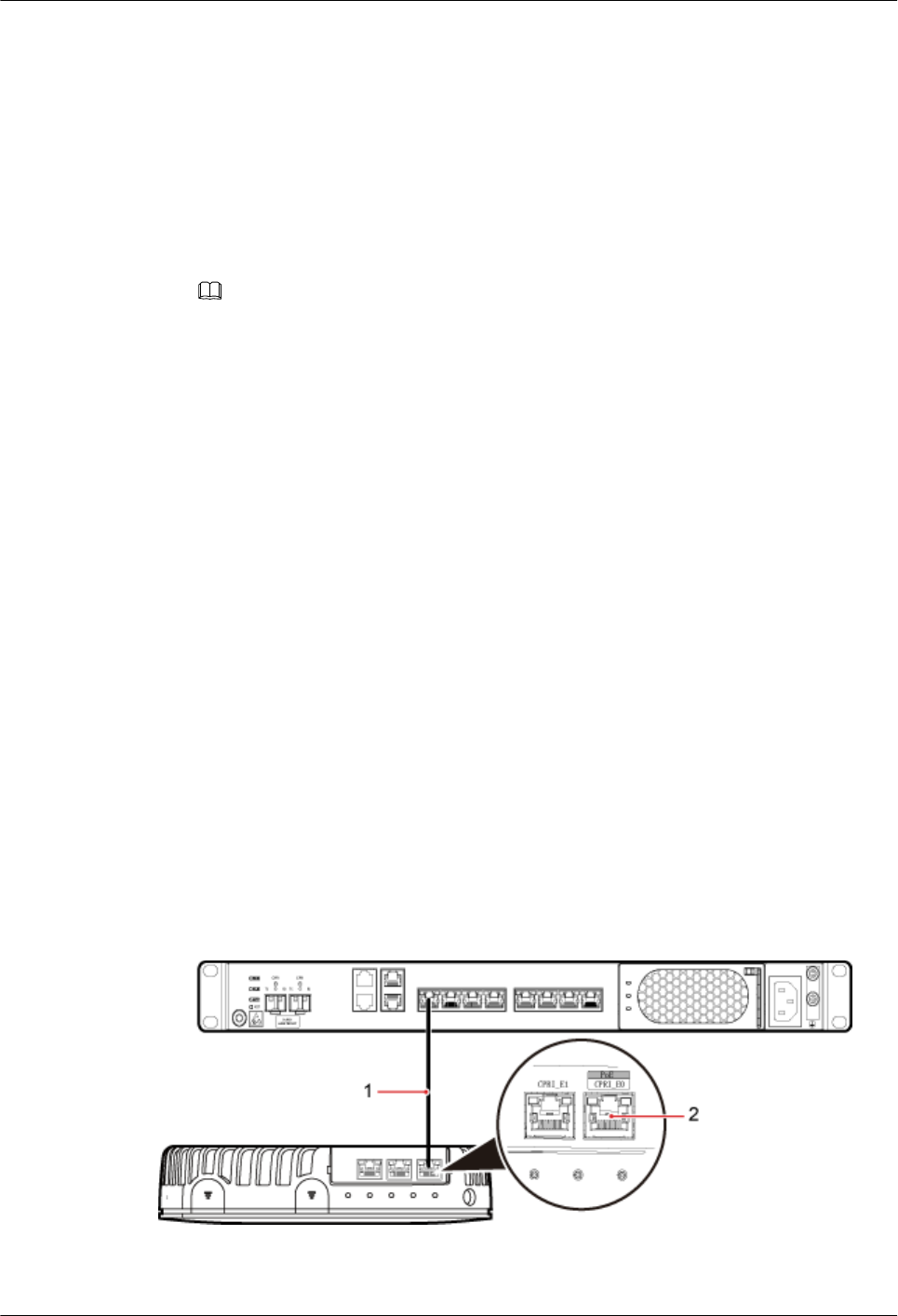
Step 5 Connect the RJ45 connector at the other end of the Ethernet cable to any port ranging from
CPRI_E0 to CPRI_E7 on the RHUB3908 panel based on the engineering design, as shown in
Figure 5-32.
Figure 5-32 Install an Ethernet cable between an RHUB3908 and a pRRU3901
(1) Ethernet cable (2) CPRI_E0 port on the pRRU3901
LampSite
Installation Guide 5 Installing an RHUB3908
Issue 08 (2015-01-15) Huawei Proprietary and Confidential
Copyright © Huawei Technologies Co., Ltd.
39
NOTE
The pRRU3901 can have two transmission ports plus PWR port or three transmission ports (plus PWR
port or no PWR port). The Ethernet cable connection between the pRRU3901 in any appearance and the
RHUB3908 is similar. This section uses the pRRU3901 with three transmission ports plus no PWR port
as an example.
----End
Follow-up Procedure
1. Route the cable, and then use a cable tie to bind the cable. For details, see 5.4.1
Requirements for Cable Layout.
2. Label the installed cable. For details, see section 8.3 Attaching an L-Shaped Label.
5.4.7 Installing CRPI Optical Cables
Optical fibers can be used to interconnect BBU and RHUB3908s, or cascade RHUB3908s.
Context
lMulti-mode optical modules for CPRI ports are labeled MM and each has a black or gray
puller.
lSingle-mode optical modules are labeled SM and each has a blue puller.
lFor details about the connection of CPRI optical cables, see Typical Networking in
LampSite Technical Description and CPRI Optical Fiber in LampSite Hardware
Description.
lAn optical module to be installed must match the rate of its corresponding port.
NOTICE
The performance of an optical module that is exposed to the air for more than 20 minutes may
be abnormal. Therefore, you must insert a fiber optic cable into an unpacked optical module
within 20 minutes.
Procedure
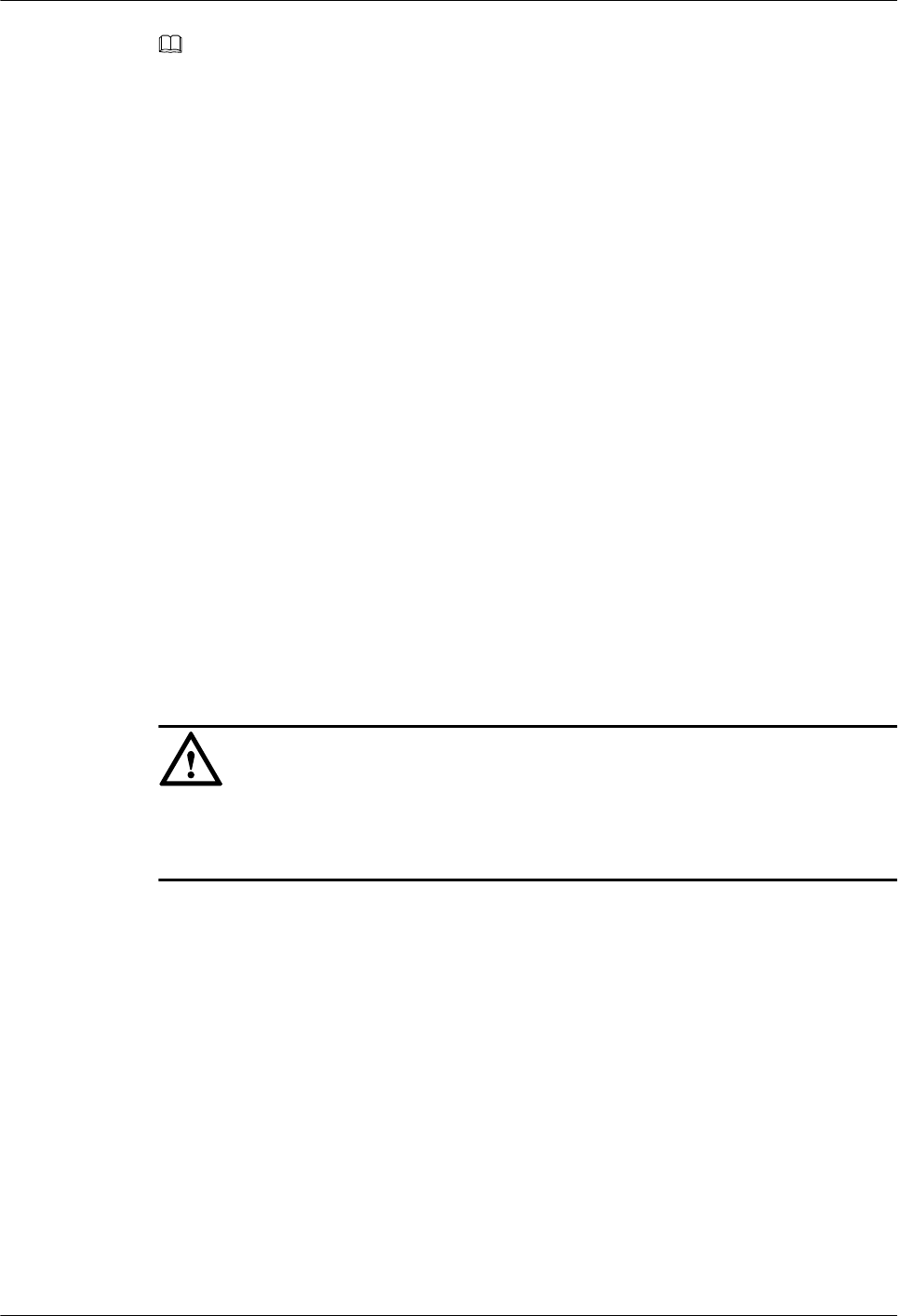
Step 1 Install an optical module, as shown in Figure 5-33 and Figure 5-34.
1. Remove the dust-proof cap from the CPRI port on the RHUB3908 panel.
2. Remove the dust-proof cap on the optical module.
3. Lower the puller of the optical module.
4. Insert the optical module into the CPRI port on the RHUB3908, BBU or ODF.
5. Raise the puller of the optical module.
LampSite
Installation Guide 5 Installing an RHUB3908
Issue 08 (2015-01-15) Huawei Proprietary and Confidential
Copyright © Huawei Technologies Co., Ltd.
40
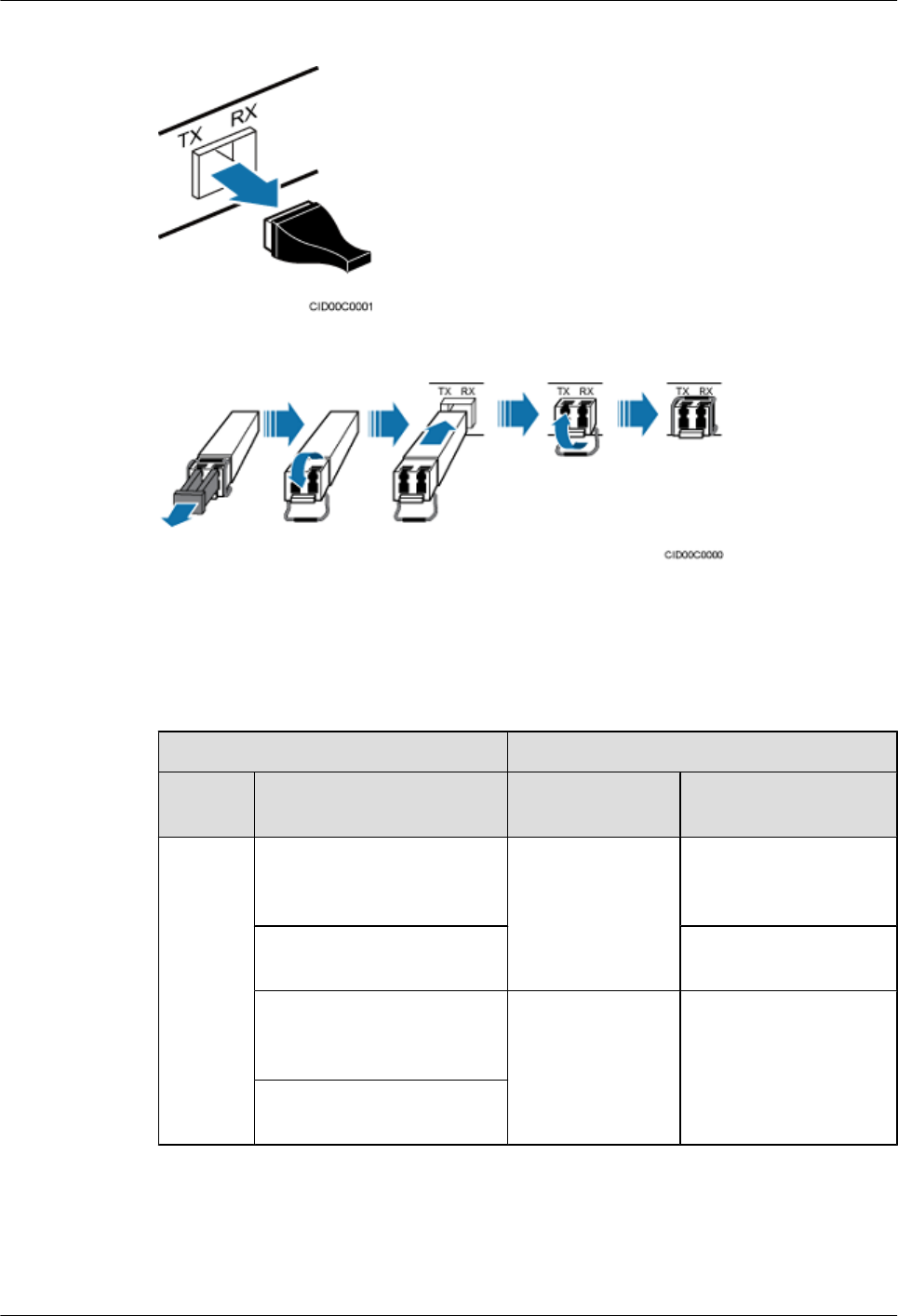
Figure 5-33 Removing the dust-proof cap from a port
Figure 5-34 Installing an optical module
Step 2 Install a CPRI optical cable, as shown in Figure 5-35.
1. Remove the dust-proof cap from the optical cable connector.
2. Install the optical cables by referring to Table 5-3.
Table 5-3 CPRI optical cable connections
One End The Other End
Connect
or
Connected to Connector Connected to
DLC
connecto
r
BBU3900/
LBBP&WBBP&UBBP/
CPRI port
DLC connector CPRI0 or CPRI1 port on
the RHUB3908
CPRI0 or CPRI1 port on the
RHUB3908
CPRI0 or CPRI1 port on
the RHUB3908
BBU3900/
LBBP&WBBP&UBBP/
CPRI port
FC, SC, or LC
connector
ODF
CPRI0 or CPRI1 port on the
RHUB3908
LampSite
Installation Guide 5 Installing an RHUB3908
Issue 08 (2015-01-15) Huawei Proprietary and Confidential
Copyright © Huawei Technologies Co., Ltd.
41
NOTE
lIf one end of the CPRI cable is connected to the DLC connector, the other end connects the BBU or
RHUB3908 through the DLC connector. If one end of the CPRI cable is connected to the ODF adapter,
the other end connects the BBU or RHUB3908 through a connector corresponding to the adapter. The
connectors include the FC connector, SC connector, and LC connector.
lWhen connecting the CPRI cable to the TX and RX ports of the optical module through connectors in
a cross manner, ensure that one end of a core of the CPRI cable is connected to the TX port and the
other end is connected to the RX port. Figure 5-35 shows how to install a CPRI optical cable for
connecting the BBU and RHUB3908s.
Figure 5-35 Installing an CRPI optical cable
----End
Follow-up Procedure
1. Route the cable, and then use a cable tie to bind the cable. For details, see 5.4.1
Requirements for Cable Layout.
2. Label the installed cable. For details, see section 8.3 Attaching an L-Shaped Label.
5.4.8 Installing an RHUB3908 Alarm Cable (Optional)
An RHUB3908 alarm cable transmits dry node alarm signals.
Prerequisites
Connectors for an alarm cable are prepared.
Context
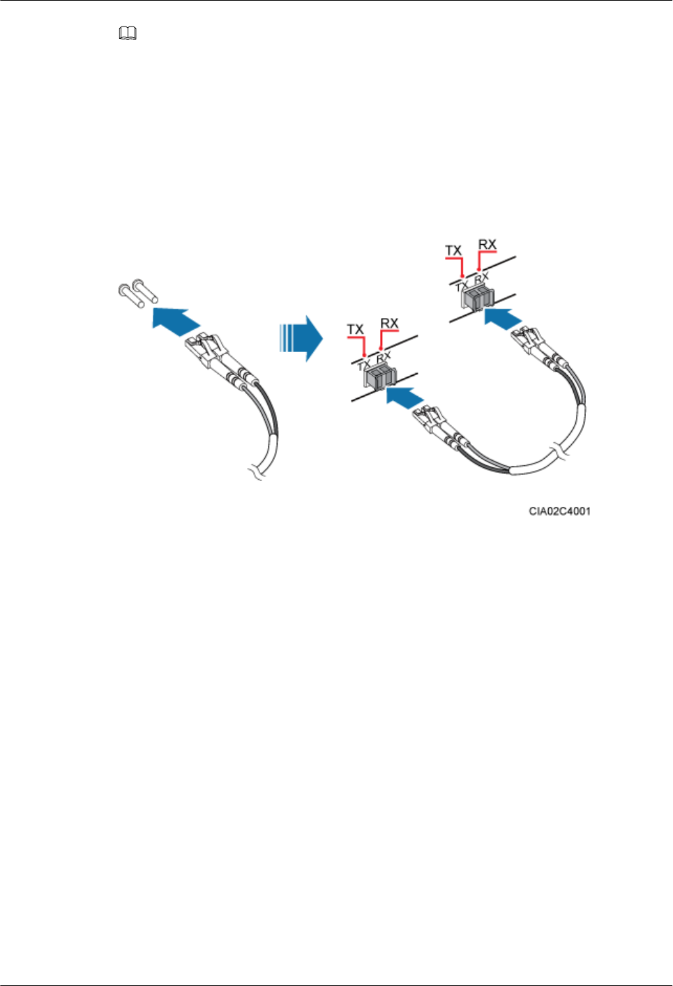
Figure 5-36 shows the exterior of an RHUB3908 alarm cable. RHUB Cable List shows the
installation position on both ends of the RHUB3908 cable.
LampSite
Installation Guide 5 Installing an RHUB3908
Issue 08 (2015-01-15) Huawei Proprietary and Confidential
Copyright © Huawei Technologies Co., Ltd.
42
Figure 5-36 RHUB3908 alarm cable
Procedure
Step 1 Connect the RJ45 connector on one end of the alarm cable to the EXT_ALM port on the
RHUB3908.
Step 2 Connect the other end of the alarm cable to the alarm cable port on the device to be monitored.
----End
Follow-up Procedure
1. Route the cable, and then use a cable tie to bind the cable. For details, see 5.4.1
Requirements for Cable Layout.
2. Label the installed cable. For details, see section 8.3 Attaching an L-Shaped Label.
5.4.9 Installing an RHUB3908 Power Cable
The RHUB3908 power cable provides 110 V AC/220 V AC power supply for the RHUB3908.
Procedure
Step 1 Route the power cable by referring to Requirements for Cable Layout.
Step 2 Connect the power connector on the X1 end to the AC power input port on the RHUB3908 panel,
as shown in Figure 5-37.
Step 3 Connect the power connector on the X2 end to the external power supply port, as shown in
Figure 5-37.
LampSite
Installation Guide 5 Installing an RHUB3908
Issue 08 (2015-01-15) Huawei Proprietary and Confidential
Copyright © Huawei Technologies Co., Ltd.
43
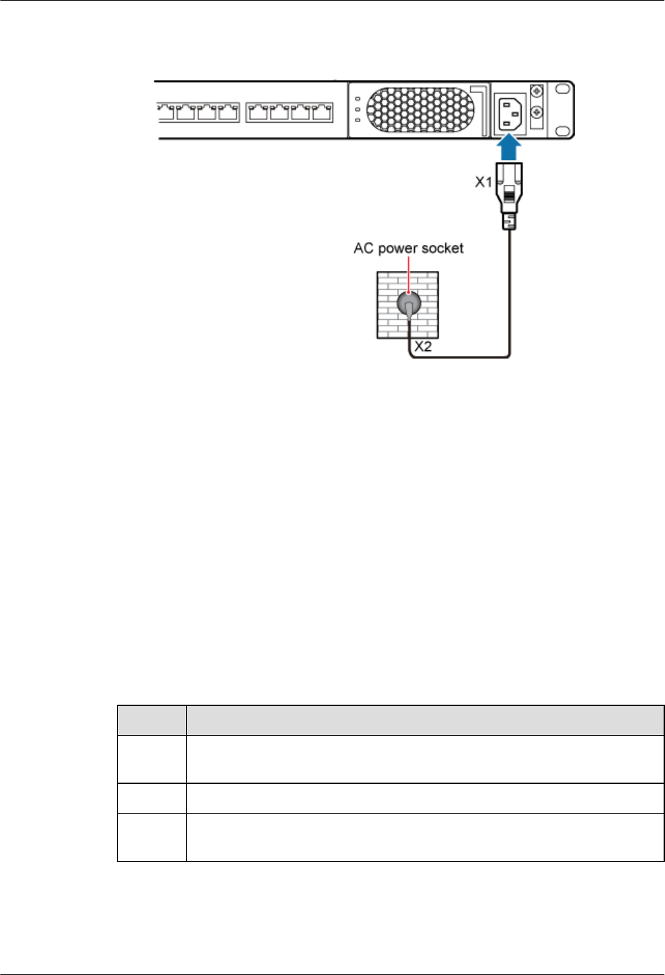
Figure 5-37 Installing an RHUB3908 power cable
----End
Follow-up Procedure
1. Route the cable, and then use a cable tie to bind the cable. For details, see 5.4.1
Requirements for Cable Layout.
2. Label the installed cable. For details, see section 8.3 Attaching an L-Shaped Label.
5.5 Checking the RHUB3908 Hardware Installation
After an RHUB3908 is installed, check the installation of hardware including the devices and
related cables.
Table 5-4 lists the hardware installation checking items.
Table 5-4 Hardware installation checking list
No. Item
1The position for each device conforms to the engineering design and meets the
space requirement.
2 Ensure that the RHUB3908 is properly installed.
3 The surface of the RHUB3908 is neat and clean. The external paint is intact. The
labels, tags, and nameplates are correct, legible, and complete.
Table 5-5 lists the checking list of the power cable and PGND cable connections.
LampSite
Installation Guide 5 Installing an RHUB3908
Issue 08 (2015-01-15) Huawei Proprietary and Confidential
Copyright © Huawei Technologies Co., Ltd.
44
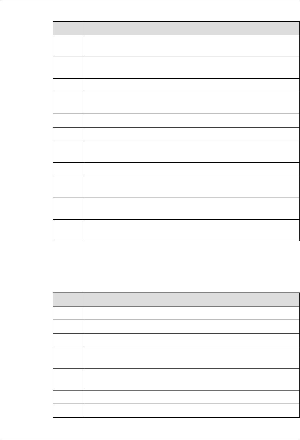
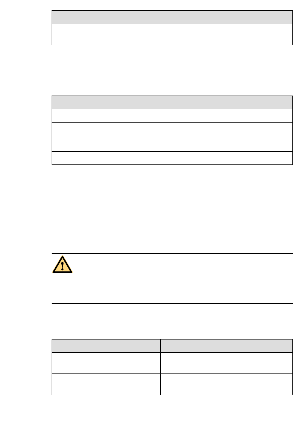
Table 5-5 Checklist for power cable and PGND cable connections
No. Item
1The power cables and PGND cables comply with the requirements of local
regulations.
2 The power cables or the PGND cables are not inversely connected or short-
circuited.
3 The power cables and PGND cables are bound separately from other cables.
4 Labels are attached to both ends of the power cables, PGND cables, optical fibers,
and Ethernet cables.
5 The power cables and PGND cables are intact.
6 The power cables and PGND cables have no weld nugget.
7 No breaking device such as a switch or fuse lies in the electric connection of the
grounding system.
8 The redundant part of PGND cable is stripped off.
9 The lugs at both ends of the power cable or PGND cable are securely soldered or
crimped.
10 The flat washers and spring washers are fixed securely and closely at all the wiring
terminals.
11 The work GND cable and PGND cable of the BTS share a group of grounding
conductors with the lightning and GND cables of the building.
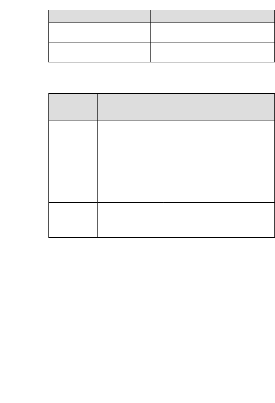
Table 5-6 lists the check items of the signal cable connection.
Table 5-6 Checklist for the signal cable connection
No. Item
1The connectors of the signal cables must securely connected.
2 The connectors of the signal cables are intact.
3 The signal cables are intact.
4 The cable ties are evenly spaced. The signal cables are bound neatly with cable
ties to proper tightness, and arranged at even intervals in the same direction.
5 The extra length of the cable ties is cut and removed. The cut surfaces of the indoor
cables are smooth and have no sharp edges.
6 The cable layout facilitates maintenance and expansion.
7 Correct and clear labels are attached to both ends of the signal cables.
LampSite
Installation Guide 5 Installing an RHUB3908
Issue 08 (2015-01-15) Huawei Proprietary and Confidential
Copyright © Huawei Technologies Co., Ltd.
45
No. Item
8The distance between the bundled fiber tails and the RHUB3908 panel is less than
70 mm.
Table 5-7 lists the checking items for other cable connections.
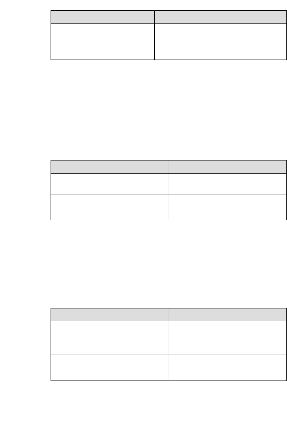
Table 5-7 Checklist for other cable connections
No. Item
1The connectors of the other cables must securely connected.
2 Labels on the cables are legible and bound based on the engineering requirements.
The cables must be bound tightly and neatly. The sheaths of the cables must not
be damaged.
3 Positions for routing the cables must meet requirements of the engineering design.
5.6 Power-on Check on an RHUB3908
This section describes the power-on check on the RHUB3908 after the RHUB3908 hardware is
installed and checked.
Context
DANGER
Power-on check involves high-voltage operation. Be cautious when conducting the power-on
check. Any direct contact with the input voltage or indirect contact through damp objects might
endanger your life.
Procedure
Step 1 Measure the RHUB3908 earth resistance.
If... Then...
The RHUB3908 earth resistance is less
than 10 ohms
Go to Step 2.
The RHUB3908 earth resistance is equal
to or larger than 10 ohms
Find out the cause and ensure that the resistance
meets requirement. Then, go to Step 2.
Step 2 Measure the voltage of the RHUB3908.
LampSite
Installation Guide 5 Installing an RHUB3908
Issue 08 (2015-01-15) Huawei Proprietary and Confidential
Copyright © Huawei Technologies Co., Ltd.
46
If... Then...
The external power supply ranges from
100 V AC to 240 V AC
Go to Step 3.
The external power supply does not
range from 100 V AC to 240 V AC
Find out the cause and ensure that the resistance
meets requirement. Then, go to Step 3.
Step 3 Power on the RHUB3908. Wait 3 to 5 minutes, check the status of the RUN indicator of the
RHUB3908 after the RHUB3908 runs properly.
If the Status of
the RUN
Indicator...
It Indicates that... Then...
Steady on The power supply is
normal while the board is
faulty.
Power off the RHUB3908, and power on it
again after rectifying the board fault.
Steady off There is no power input
or the board is faulty.
Power off the RHUB3908, and check the
power input again. Rectify the board faulty
and power on the RHUB3908 again if the
power input is normal.
On for 1s and off
for 1s
The devices work
properly.
End the operation.
On for 0.125s and
off for 0.125s
The board software is
being uploaded.
Power off the RHUB3908 if the uploading is
not finished in 5 minutes, and check whether
the configuration file is correct. Power on the
RHUB3908 again after the fault is rectified.
----End
LampSite
Installation Guide 5 Installing an RHUB3908
Issue 08 (2015-01-15) Huawei Proprietary and Confidential
Copyright © Huawei Technologies Co., Ltd.
47

6 Installing a pRRU3901
About This Chapter
This chapter describes the pRRU3901 installation process. The pRRU3901 can have two
transmission ports (plus PWR port) or three transmission ports (plus PWR port or no PWR port).
Unless otherwise specified, this document uses the pRRU3901 with three transmission ports
plus no PWR port as an example.
NOTE
The pRRU3901 with three transmission ports plus no PWR port is named the pRRU3901a in North
Americain.
6.1 Information About the Installation
This section describes the information that you must be familiar with before installing a
pRRU3901, including the pRRU3901 product family, installation scenarios, installation space
and environment requirements.
6.2 Obtaining the MAC Address (Optional)
Before installing a pRRU3901, record the media access control (MAC) address, which will be
used during pRRU3901 commissioning. This section applies only when a pRRU3901 with three
transmission ports is configured with a Wi-Fi daughter board.
6.3 Installation Process
This section describes the pRRU3901 installation process, which involves installing a
pRRU3901, and cables, checking the pRRU3901 hardware installation, and powering on the
pRRU3901.
6.4 Installing a pRRU3901
This section describes the pRRU3901 installation process. A pRRU3901 can be installed on a
wall, ceiling, indoor metal pole, or keel.
6.5 Installing pRRU3901 Cables
This section describes the procedure of installing the pRRU3901 cables.
6.6 Checking the pRRU3901 Hardware Installation
pRRU3901 hardware installation checking includes hardware and cable installation checking.
6.7 Powering on the pRRU3901
LampSite
Installation Guide 6 Installing a pRRU3901
Issue 08 (2015-01-15) Huawei Proprietary and Confidential
Copyright © Huawei Technologies Co., Ltd.
48

This section describes the power-on check on the pRRU3901 after the pRRU3901 hardware is
installed and checked.
LampSite
Installation Guide 6 Installing a pRRU3901
Issue 08 (2015-01-15) Huawei Proprietary and Confidential
Copyright © Huawei Technologies Co., Ltd.
49
6.1 Information About the Installation
This section describes the information that you must be familiar with before installing a
pRRU3901, including the pRRU3901 product family, installation scenarios, installation space
and environment requirements.
6.1.1 pRRU3901 Product Family
This chapter describes the configurations and functions of the pRRU3901 components.
Table 6-1 lists the pRRU3901 product family.
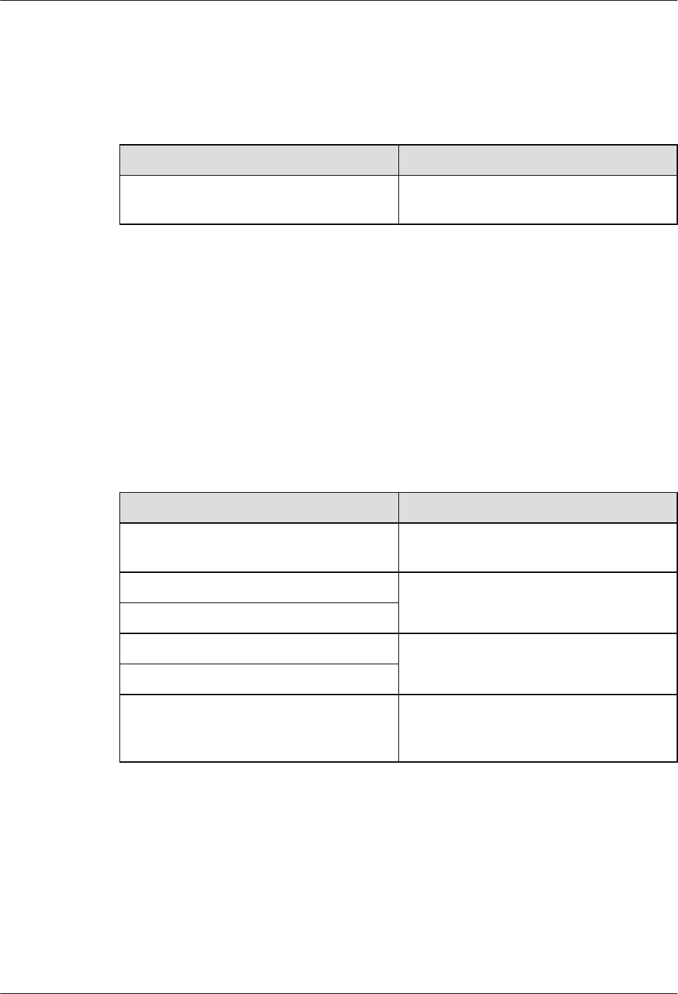
Table 6-1 pRRU3901 product family
Categor
y
Equipment Optional
Item
Quantity Function
Main
equipmen
t
pRRU3901 Mandatory 1 Processes the radio frequency
signals.
External
antenna
Optional 2 Provides external antennas for
the pRRU3901.
NOTE
Configure two external antennas
for each RF daughter board.
Auxiliary
device
Mounting kits Mandatory 1 Supports the pRRU3901
installation on a wall, pole,
ceiling, or keel. The mounting
kits vary with the pRRU3901
installation mode.
Extender Optional 1 Extends the distance between
the pRRU3901 and
RHUB3908.
6.1.2 pRRU3901 Installation Scenario
The pRRU3901 can be installed on a wall, ceiling, pole, or keel. The following table describes
the installation in different scenarios.
Installing a pRRU3901 on a wall
NOTE
lThe pRRU3901 must keep a minimum of 0.5 m away from the power equipment with interference,
and keep a minimum of 2 m away from the source with radiation.
lThe pRRU3901 must keep away from a metal wall to avoid the impact on the antenna performance.
When a pRRU3901 is installed on a wall, installation modes vary with the quality of wall, as
shown in Table 6-2.
LampSite
Installation Guide 6 Installing a pRRU3901
Issue 08 (2015-01-15) Huawei Proprietary and Confidential
Copyright © Huawei Technologies Co., Ltd.
50
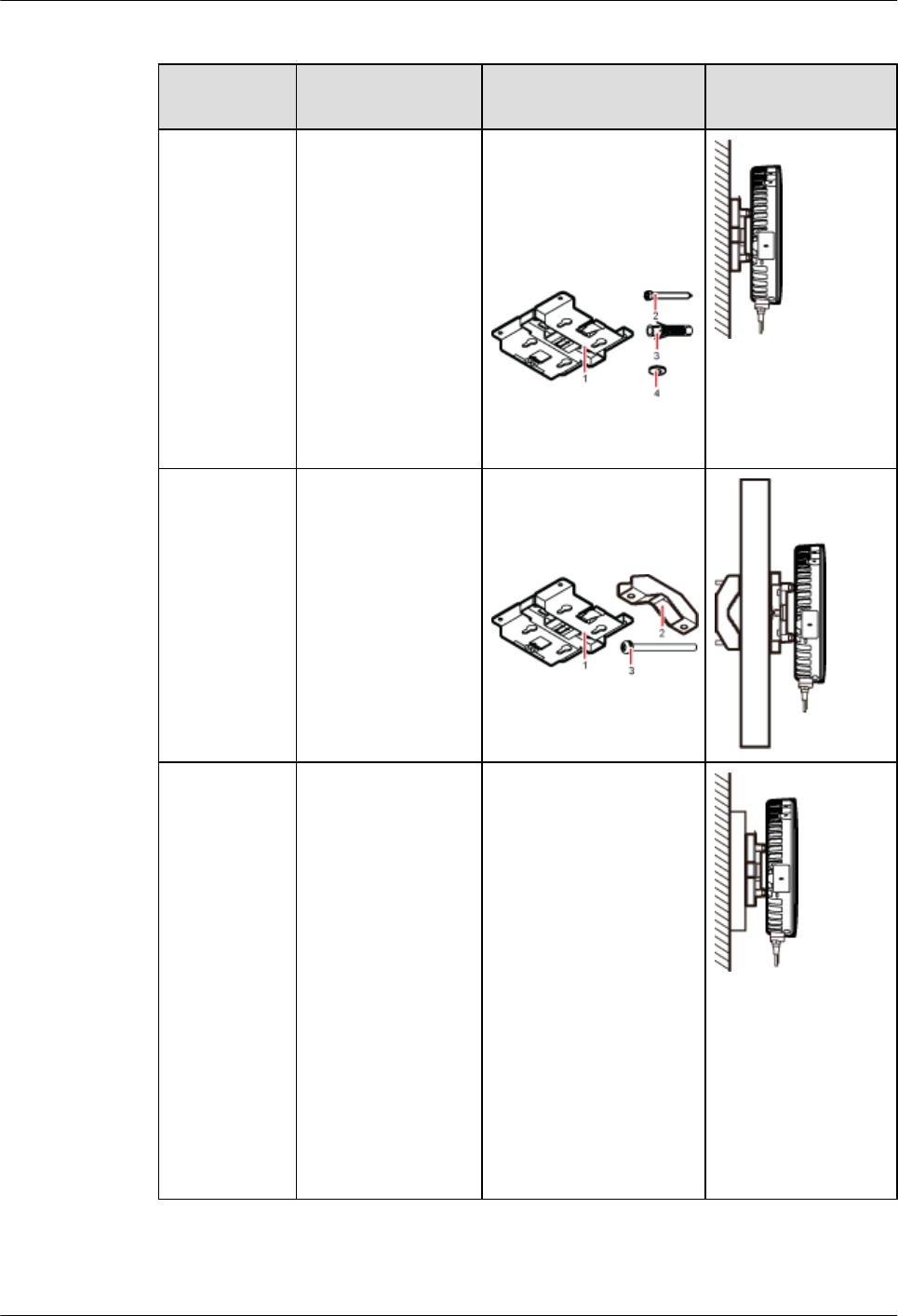
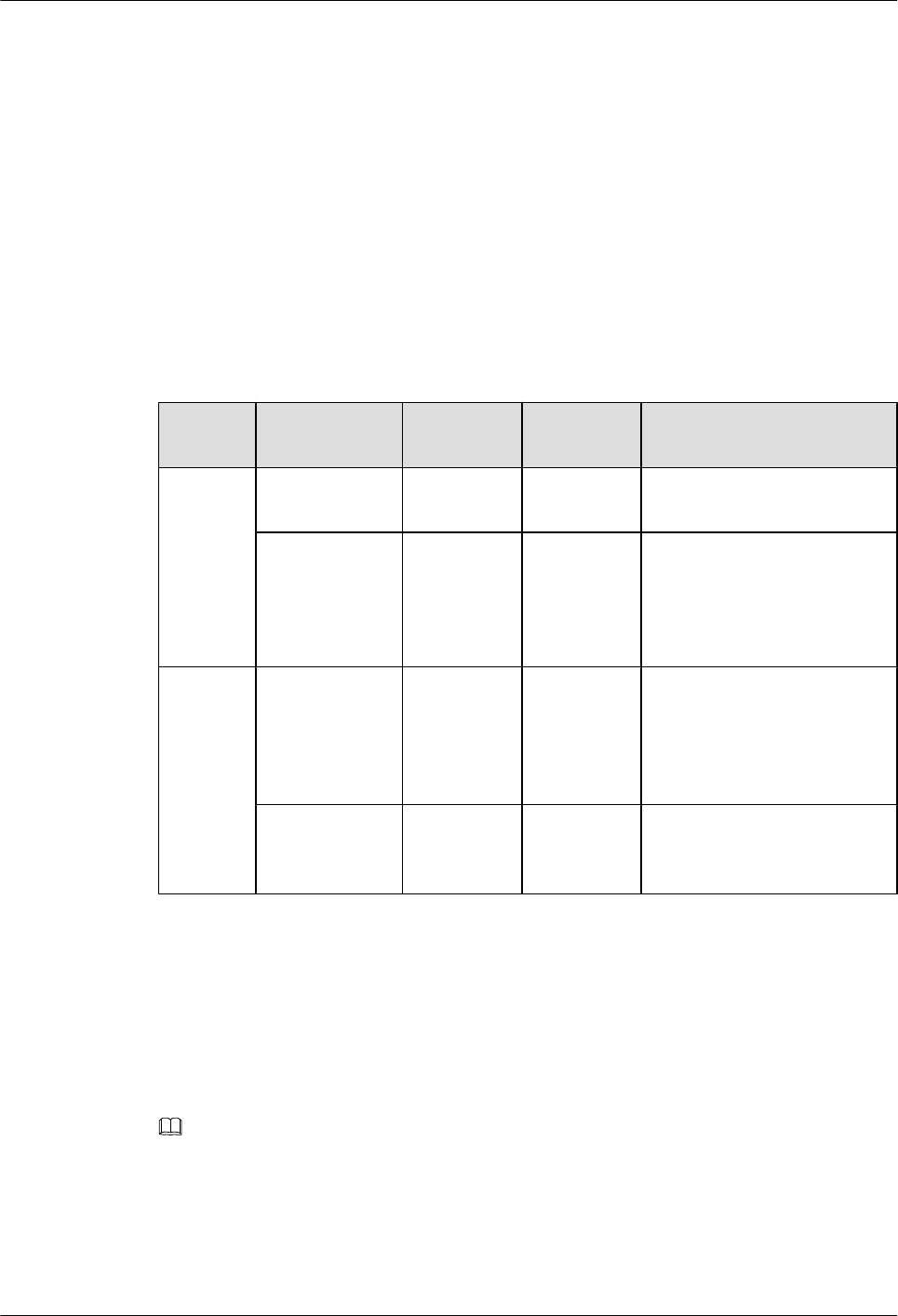
Table 6-2 Wall-mounted suggestion
Installation
Mode
Requirements Mounting Brackets Installation
Diagram
Installing the
pRRU3901 on
a wall by
drilling holes
For details, see
pRRU
Installed on a
Wall.
lThe wall can bear
a load at least four
times the weight
of a pRRU3901.
lThe screws must
be tightened with
a torque of 10
N·m. This ensures
the screws work
properly and the
wall remains
intact without
cracks in it.
1. Plate
2. Screw (M6X50)
3. Plastic expansion
sleeve
4. Flat washer
Installing the
pRRU3901 on
a wall using a
V clamp
through an
attachment
plate
For details, see
pRRU
Installed on a
Plate.
lThe wall can bear
a load at least four
times the weight
of a pRRU3901.
lThe thickness of
the wall is less
than the bolt
length (80 mm).
1. Plate
2. V clamp
3. Bolt (M6X80)
Installing the
pRRU3901 on
a wall using a
plate on a
metal wall
lThe wall cannot
bear a load at least
four times the
weight of the
pRRU3901. For
example, EPS
walls, MDF
walls, or walls
cannot be drilled.
lThe wall is too
thick to drill, and
the pRRU3901
cannot be
installed on a wall
using a V clamp
through an
attachment plate.
The plate is prepared by
customers.
LampSite
Installation Guide 6 Installing a pRRU3901
Issue 08 (2015-01-15) Huawei Proprietary and Confidential
Copyright © Huawei Technologies Co., Ltd.
51
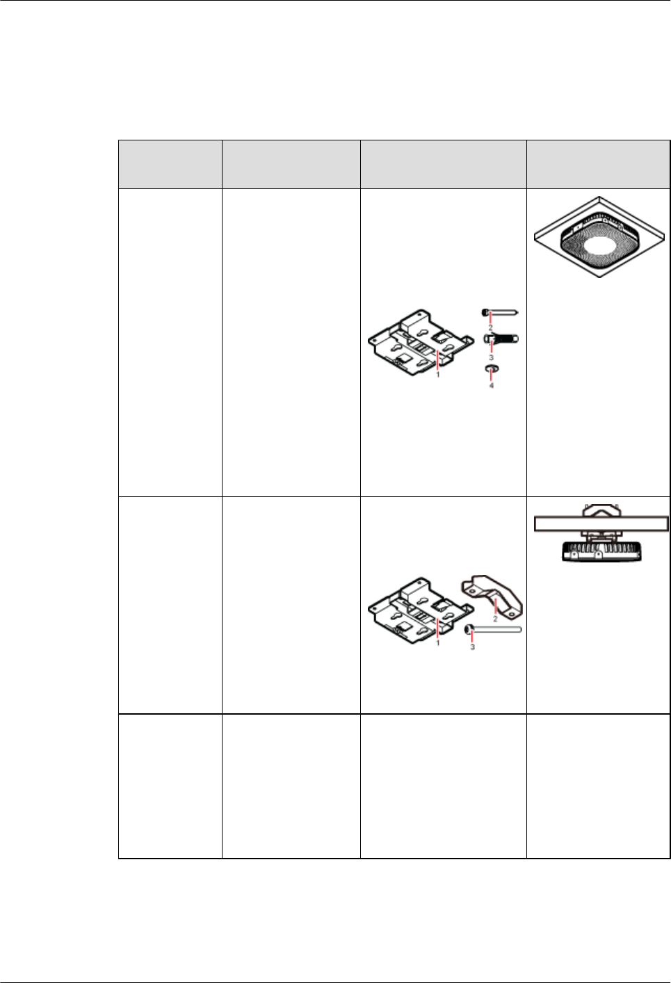
Installing a pRRU3901 on a ceiling
When a pRRU3901 is installed on a ceiling, installation modes vary with the quality of the
ceiling, as shown in Table 6-3.
Table 6-3 Ceiling-mounted suggestion
Installation
Mode
Requirements Mounting Brackets Installation
Diagram
Installing the
pRRU3901 on
a ceiling by
drilling holes
For details, see
pRRU
Installed on a
Ceiling.
lThe ceiling, such
as a concrete
ceiling, can bear a
load at least four
times the weight
of the
pRRU3901.
lThe screws must
be tightened with
a torque of 10
N·m. This ensures
the screws work
properly and the
ceiling remains
intact without
cracks in it.
1. Plate
2. Screw (M6X50)
3. Plastic expansion
sleeve
4. Flat washer
Installing the
pRRU3901 on
a ceiling using
a V clamp
through an
attachment
plate
For details, see
pRRU
Installed on a
Plate.
lThe ceiling, such
as a concrete
ceiling, can bear a
load at least four
times the weight
of the
pRRU3901.
lThe thickness of
the ceiling is less
than the bolt
length (80 mm).
1. Plate
2. V clamp
3. Bolt (M6X80)
Installing the
pRRU3901 on
a pole
For details, see
pRRU
Installed on a
Pole.
A pole under the
ceiling can bear a
load at least four
times the weight of
the pRRU3901.
For details, see Table
6-4.
For details, see Table
6-4.
LampSite
Installation Guide 6 Installing a pRRU3901
Issue 08 (2015-01-15) Huawei Proprietary and Confidential
Copyright © Huawei Technologies Co., Ltd.
52
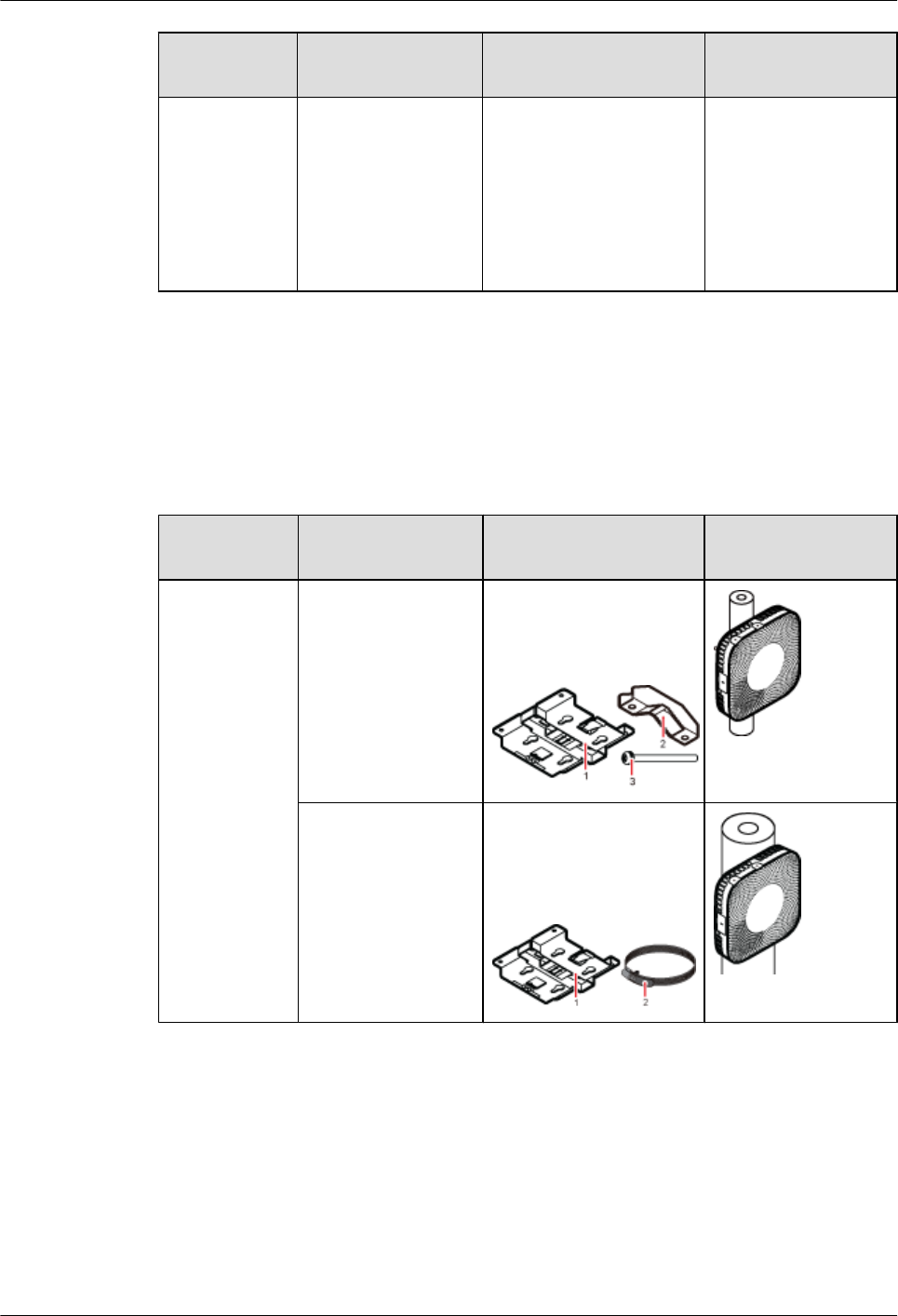
Installation
Mode
Requirements Mounting Brackets Installation
Diagram
Installing the
pRRU3901 on
a keel
For details, see
pRRU
Installed on a
Keel.
A keel under the
ceiling can bear a
load at least four
times the weight of
the pRRU3901.
For details, see Table
6-5.
For details, see Table
6-5.
Installing the pRRU3901 on a pole
When a pRRU3901 is installed on a pole, installation modes vary with the diameter of the pole,
as shown in Table 6-4.
Table 6-4 Pole-mounted suggestion
Installation
Mode
Requirements Mounting Brackets Installation
Diagram
Installing the
pRRU3901 on
a pole
For details, see
pRRU
Installed on a
Pole.
The diameter of the
pole ranges from 30
mm to 70 mm.
1. Plate
2. V clamp
3. Bolt (M6X80)
The diameter of the
pole ranges from 70
mm to 110 mm.
1. Plate
2. Hose clamp, which is
prepared by the
customer
Installing the pRRU3901 on a keel
The pRRU3901 can be installed on a keel of U-shape, T-shape, or H-shape. For the keels of
other shapes, they are determined based on the onsite requirements.
LampSite
Installation Guide 6 Installing a pRRU3901
Issue 08 (2015-01-15) Huawei Proprietary and Confidential
Copyright © Huawei Technologies Co., Ltd.
53
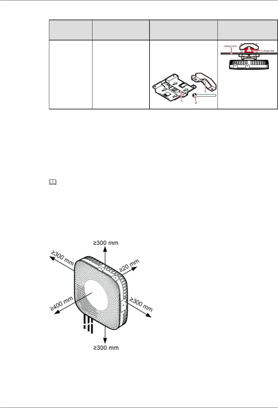
Table 6-5 Keel-mounted installation suggestion
Installation
Mode
Requirements Mounting Brackets Installation
Diagram
Installing the
pRRU3901 on
a keel
For details, see
pRRU
Installed on a
Keel.
The keel is in U-
shape, T-shape, H-
shape, or other
shapes.
1. Plate
2. V clamp
3. Bolt (M6X80)
shows the pRRU3901
installed on a U-
shaped keel.
6.1.3 Space Requirements
When the pRRU3901 is installed on a wall, ceiling, pole or keel, the minimum space is required
for easy cabling and O&M. Based on the engineering practice, the recommendation for the
installation space is provided.
NOTE
During installation, a minimum clearance of 2 m must be reserved between the pRRU3901 working on the
2.6 GHz band and the Wi-Fi module if they need to process services concurrently.
Figure 6-1 shows the recommended space requirements of the pRRU3901 when the external
antenna is required.
Figure 6-1 Recommended space requirements of the pRRU3901
When the external antenna is required, the recommended space for installing a single pRRU3901
is described as follows:
lAt least 300 mm above the pRRU3901 is reserved for maintenance.
lAt least 300 mm under the pRRU3901 is reserved for cabling.
LampSite
Installation Guide 6 Installing a pRRU3901
Issue 08 (2015-01-15) Huawei Proprietary and Confidential
Copyright © Huawei Technologies Co., Ltd.
54
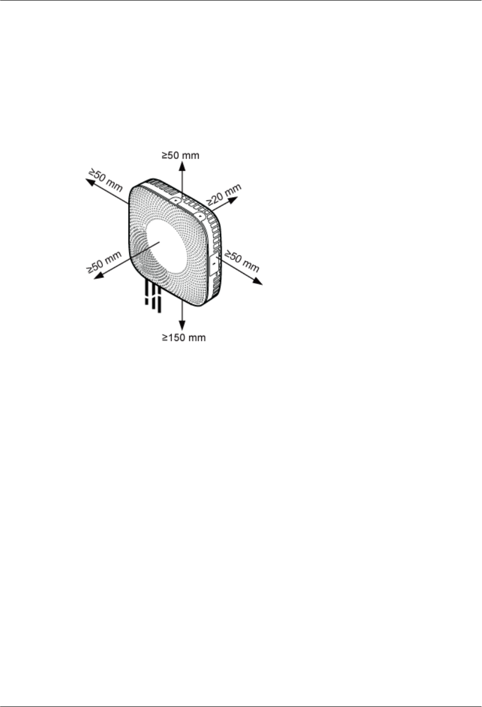
lAt least 300 mm on the left of the pRRU3901 is reserved for maintenance.
lAt least 300 mm on the right of the pRRU3901 is reserved for maintenance.
lAt least 400 mm in front of the pRRU3901 is reserved for maintenance
lAt least 20 mm on the back of the pRRU3901 is reserved for ventilation.
Figure 6-2 shows the minimum space requirements of the pRRU3901 when the external antenna
is not required.
Figure 6-2 Minimum space requirements of the pRRU3901
When the external antenna is not required, the minimum space for installing a single pRRU3901
is described as follows:
lAt least 50 mm above the pRRU3901 is reserved for maintenance.
lAt least 150 mm under the pRRU3901 is reserved for cabling.
lAt least 50 mm on the left of the pRRU3901 is reserved for maintenance.
lAt least 50 mm on the right of the pRRU3901 is reserved for maintenance.
lAt least 50 mm in front of the pRRU3901 for maintenance.
lAt least 20 mm on the back of the pRRU3901 is reserved for ventilation.
6.1.4 pRRU3901 Installation Environment Requirements
The installation environment of a pRRU3901 involves the running environment specifications
for the pRRU3901 and other specifications.
pRRU3901 Running Environment Specifications
Table 6-6 shows the environment specifications for the pRRU3901 installed indoors.
LampSite
Installation Guide 6 Installing a pRRU3901
Issue 08 (2015-01-15) Huawei Proprietary and Confidential
Copyright © Huawei Technologies Co., Ltd.
55

Table 6-6 pRRU3901 environment specifications
Specificat
ions
Condition Remarks
Operating
temperatur
e
- 5°C to + 40°C -
Relative
humidity
5% RH to 95% RH -
Altitude - 60 m to + 1800 m Works properly.
1800 m to 4000 m Above the 1800 m altitude, the
maximum operating temperature
decreases by 1°C each time the altitude
increases by 220 m.
Other Running Environment Specifications
lThe pRRU3901 cannot be installed at an air outlet of the heat dissipation box of an air
conditioner or other heat-generating appliances.
lThe pRRU3901 cannot be installed near a strong heat source.
lThe pRRU3901 cannot be installed in a position with water dripping, such as outdoor
equipment of air conditioners, pipe, and leaking or dripping roofs.
lThe installation position must be far from rains. If the pRRU3901 is installed on a wall,
there must be no window on either side of the wall.
lThe installation position must be far away from high voltage, highly corrosive devices,
flammable or explosive substances, and electromagnetic interference.
lThe pRRU3901 must be installed in a dry, ventilating, and dust-proof place.
lIf the pRRU3901 is installed in parking areas or basements, the installation position must
be well-ventilated.
6.2 Obtaining the MAC Address (Optional)
Before installing a pRRU3901, record the media access control (MAC) address, which will be
used during pRRU3901 commissioning. This section applies only when a pRRU3901 with three
transmission ports is configured with a Wi-Fi daughter board.
Context
The MAC address indicates the IP address through which a device can be reached.
Procedure
Step 1 Remove the backup WIFI MAC label from the front housing of the pRRU3901 and keep them
secure, as shown in Figure 6-3.
LampSite
Installation Guide 6 Installing a pRRU3901
Issue 08 (2015-01-15) Huawei Proprietary and Confidential
Copyright © Huawei Technologies Co., Ltd.
56
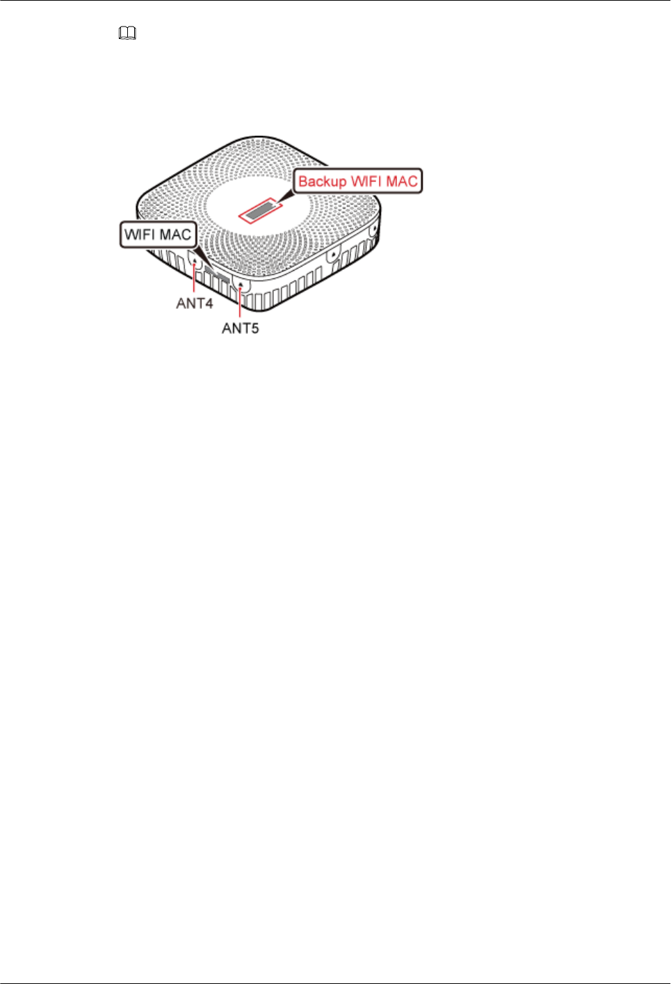
NOTE
lDo not remove the WIFI MAC label on the side of the pRRU3901 housing.
lBefore removing the backup WIFI MAC label, photograph it.
Figure 6-3 Removing backup WIFI MAC label
Step 2 Save the MAC according to MAC Collection Template, and report it to the pRRU3901
commissioning personnel.
----End
6.3 Installation Process
This section describes the pRRU3901 installation process, which involves installing a
pRRU3901, and cables, checking the pRRU3901 hardware installation, and powering on the
pRRU3901.
Figure 6-4 shows the pRRU3901 installation process.
LampSite
Installation Guide 6 Installing a pRRU3901
Issue 08 (2015-01-15) Huawei Proprietary and Confidential
Copyright © Huawei Technologies Co., Ltd.
57
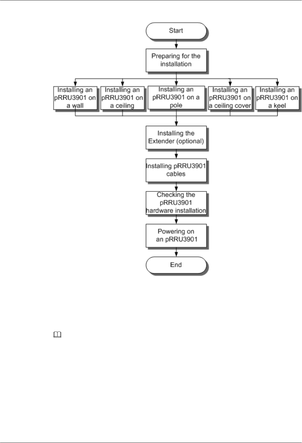
Figure 6-4 pRRU3901 installation process
6.4 Installing a pRRU3901
This section describes the pRRU3901 installation process. A pRRU3901 can be installed on a
wall, ceiling, indoor metal pole, or keel.
NOTE
lThe pRRU3901 cannot be grounded. If the pRRU3901 is grounded but the RHUB3908 connected to
this pRRU3901 is not, the pRRU3901 may fail to be powered on.
lA minimum distance of 50 cm must be reserved between the pRRU3901 and the incandescent lamp.
lThe installation spacing between the pRRU3901 and the temperature sensor must be greater than 50
cm.
lIt is good practice to install the pRRU3901 on materials that can tolerate a temperature higher than 65°
C and have an ignition point higher than 70°C.
6.4.1 pRRU3901 Installation Kits
This section describes the pRRU3901 installation kits.
LampSite
Installation Guide 6 Installing a pRRU3901
Issue 08 (2015-01-15) Huawei Proprietary and Confidential
Copyright © Huawei Technologies Co., Ltd.
58
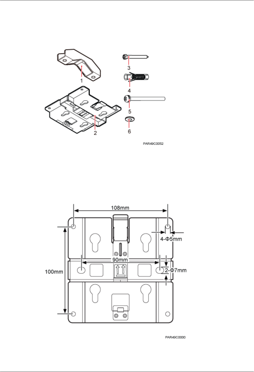
Figure 6-5 shows the exterior of the pRRU3901 installation kits.
Figure 6-5 pRRU3901 installation kits
(1) V clamp (2) Plate (3) Screw (M6x50)
(4) Plastic expansion sleeve (5) Bolt (M6x80) (6) Flat washer
The following figure shows the specifications of the installation plate.
Figure 6-6 Plate specifications
LampSite
Installation Guide 6 Installing a pRRU3901
Issue 08 (2015-01-15) Huawei Proprietary and Confidential
Copyright © Huawei Technologies Co., Ltd.
59
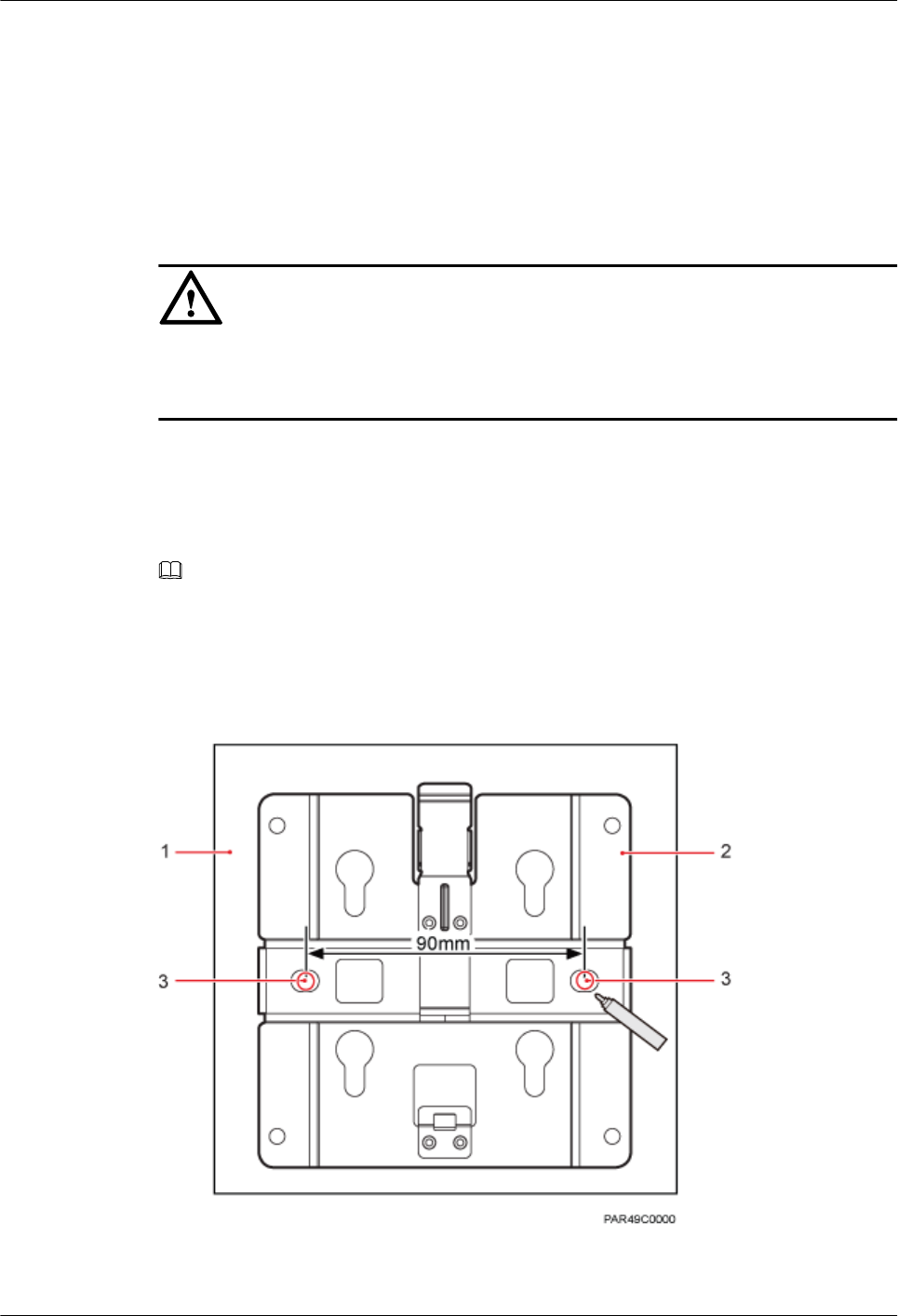
6.4.2 pRRU3901 Installed on a Wall
If the wall indoors has sufficient load bearing capacity and space, the pRRU3901 is
recommended to install on a wall. If the wall cannot bear the capacity, choose an installation
mode based on site requirements.
Context
NOTICE
This section only describes the procedure of installing the pRRU3901 on a wall without any
other auxiliary devices. The installation procedure of other wall-mounted modes is similar to
that of installing the pRRU3901 on a wall without auxiliary devices.
Procedure
Step 1 Determine the position for installing the pRRU3901 based on the construction blueprint and the
space requirements.
NOTE
For pRRU3901 installation space requirements, see Space Requirements.
Step 2 Place the plate in the installation position against the wall. Then, level the plate and mark the
two anchor points using a marker, as shown in Figure 6-7.
Figure 6-7 Anchor points of the pRRU3901 installation kits (unit: mm)
(1) Wall (2) Plate (3) Anchor point
LampSite
Installation Guide 6 Installing a pRRU3901
Issue 08 (2015-01-15) Huawei Proprietary and Confidential
Copyright © Huawei Technologies Co., Ltd.
60
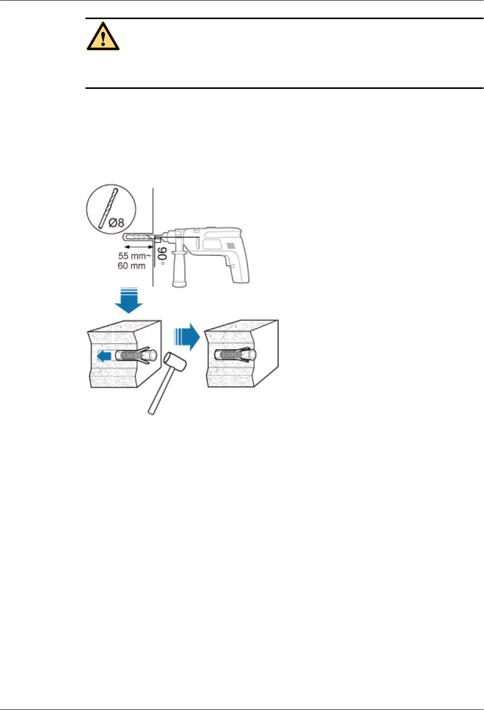
CAUTION
To prevent inhalation or eye contact with dust, take adequate preventive measures when drilling
holes.
Step 3 Use a hammer drill with a φ 8 bit to drill holes at the marked anchor points as shown in as shown
in Figure 6-8. Use the cleaner to clean the dust inside and around the holes and measure the
distance between them. If they are inaccurately positioned, re-measure and re-drill the holes.
Then, use a rubber mallet to push the two plastic expansion sleeve into the holes.
Figure 6-8 Drilling holes and installing expansion bolts
Step 4 Lead the M6x50 screw through the washer, and then through the drilling holes of the plate to
the plastic expansion sleeve, and tighten the screw to a torque of 5 N•m, as shown in Figure
6-9.
LampSite
Installation Guide 6 Installing a pRRU3901
Issue 08 (2015-01-15) Huawei Proprietary and Confidential
Copyright © Huawei Technologies Co., Ltd.
61
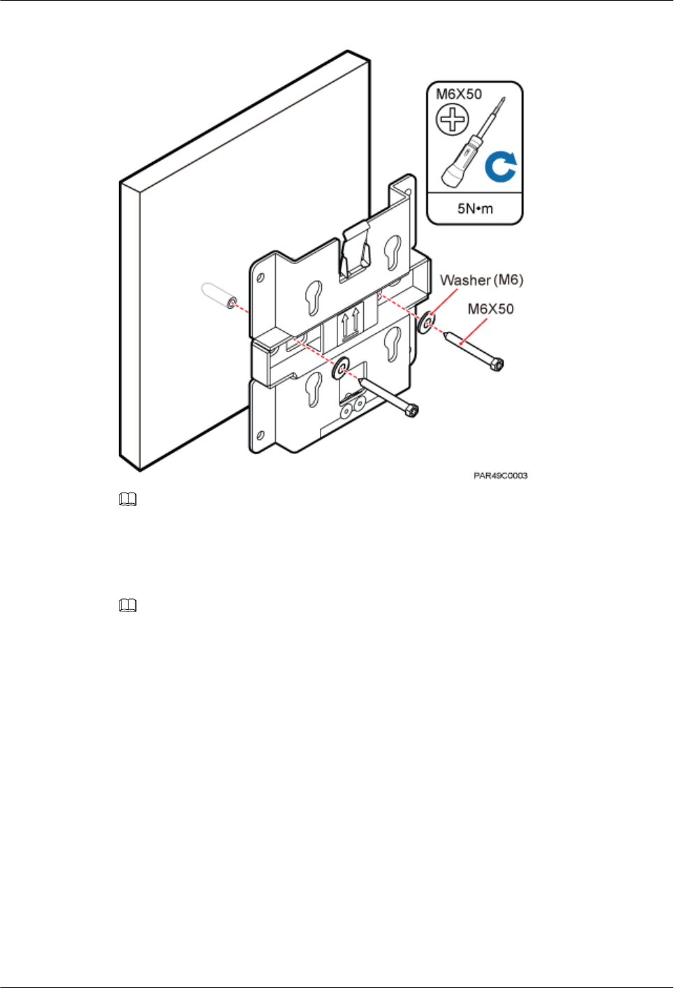
Figure 6-9 Installing the plate
NOTE
If the screws cannot be tightened using a Phillips screwdriver, use a hex key or an electric screwdriver to
assist the installation.
Step 5 Fit the four hooks of the pRRU3901 into the installation kits, as shown in Figure 6-10. If the
hooks are properly installed, a slight clack can be heard.
NOTE
It is recommended that you observe the installation from one side of the pRRU3901 when inserting hooks
into the kits.
LampSite
Installation Guide 6 Installing a pRRU3901
Issue 08 (2015-01-15) Huawei Proprietary and Confidential
Copyright © Huawei Technologies Co., Ltd.
62
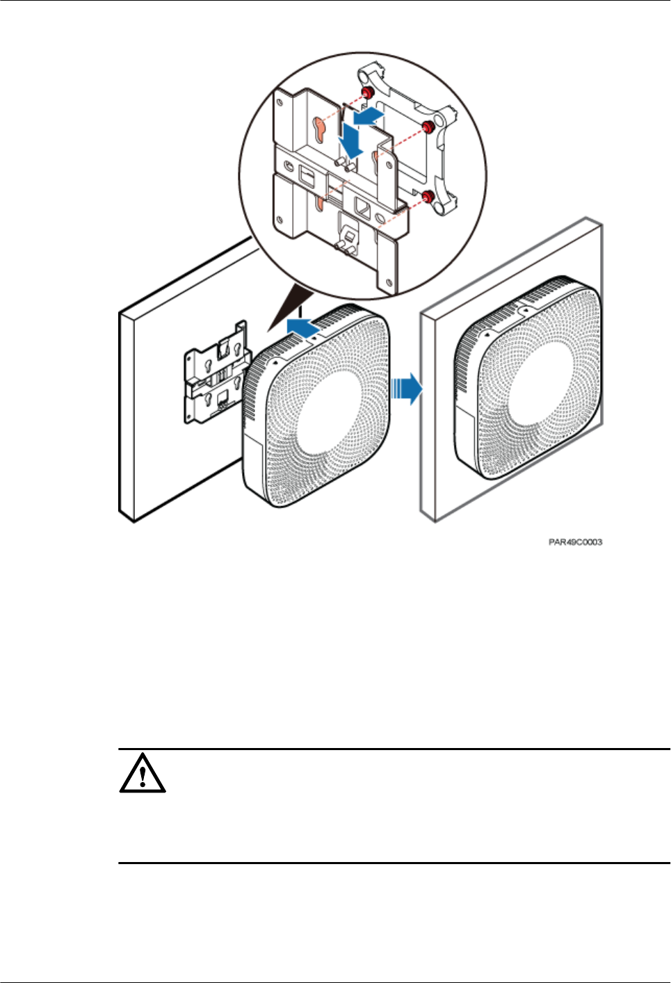
Figure 6-10 Installing the pRRU3901 on a plate
----End
6.4.3 pRRU3901 Installed on a Ceiling
This section describes the procedure of installing a pRRU3901 on the ceiling, such as the
concrete ceiling, when the ceiling has sufficient load bearing capacity and installation space.
Context
NOTICE
If the pRRU3901 is installed on the ceiling, the temperature of the ceiling may increase by a
maximum of 30 degrees. Therefore, whether a pRRU3901 can be installed on a ceiling depends
on the ceiling material.
Procedure
Step 1 Determine the position for installing the pRRU3901 based on the construction blueprint and the
space requirements.
LampSite
Installation Guide 6 Installing a pRRU3901
Issue 08 (2015-01-15) Huawei Proprietary and Confidential
Copyright © Huawei Technologies Co., Ltd.
63
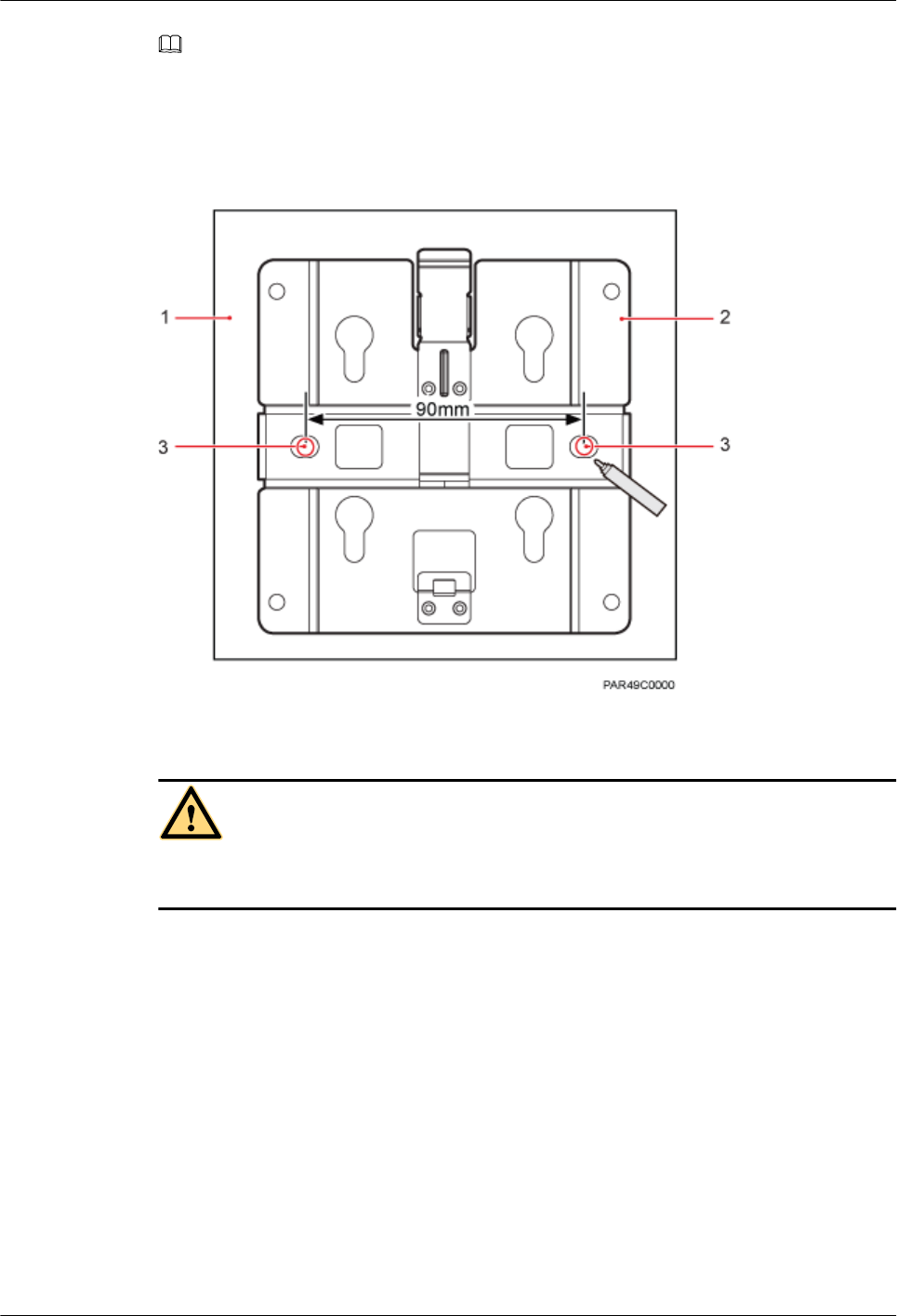
NOTE
For pRRU3901 installation space requirements, see Space Requirements.
Step 2 Place the plate in the installation position against the ceiling. Then, level the plate and mark the
two anchor points using a marker, as shown in Figure 6-11.
Figure 6-11 Anchor points of the pRRU3901 installation kits (unit: mm)
(1) Ceiling (2) Plate (3) Anchor point of the bolt
CAUTION
To prevent inhalation or eye contact with dust, take adequate preventive measures when drilling
holes.
Step 3 Use a hammer drill with a φ 8 bit to drill holes at the marked anchor points as shown in as shown
in Figure 6-12. Use the cleaner to clean the dust inside and around the holes and measure the
distance between them. If they are inaccurately positioned, re-measure and re-drill the holes.
Then, use a rubber mallet to push the two plastic expansion sleeve into the holes.
LampSite
Installation Guide 6 Installing a pRRU3901
Issue 08 (2015-01-15) Huawei Proprietary and Confidential
Copyright © Huawei Technologies Co., Ltd.
64
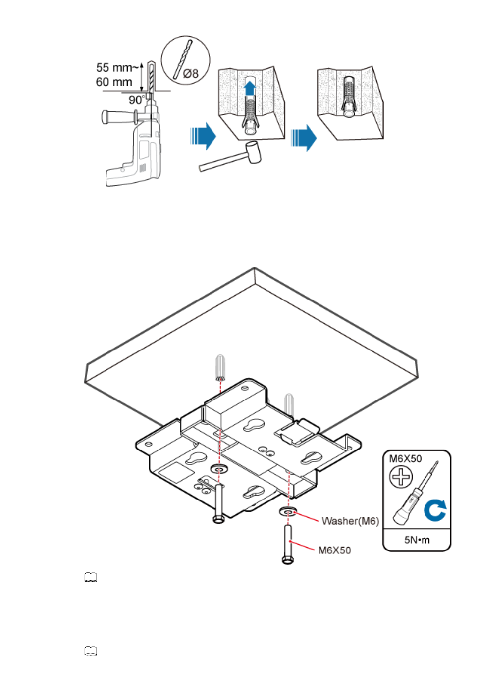
Figure 6-12 Drilling holes and installing expansion bolts
Step 4 Lead the M6x50 screw through the washer, and then through the drilling holes of the plate to
the plastic expansion sleeve, and use a torque screwdriver to tighten the screw with a torque of
5 N•m, as shown in Figure 6-13.
Figure 6-13 Installing the plate
NOTE
If the screws cannot be tightened using a Phillips screwdriver, use a hex key or an electric screwdriver to
assist the installation.
Step 5 Fit the four hooks of the pRRU3901 into the installation kits, as shown in Figure 6-14. If the
hooks are properly installed, a slight clack can be heard.
NOTE
It is recommended that you observe the installation from one side of the pRRU3901 when inserting hooks
into the kits.
LampSite
Installation Guide 6 Installing a pRRU3901
Issue 08 (2015-01-15) Huawei Proprietary and Confidential
Copyright © Huawei Technologies Co., Ltd.
65
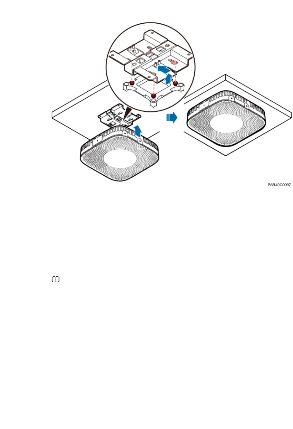
Figure 6-14 Installing a pRRU3901
----End
6.4.4 pRRU3901 Installed on a Pole
A pRRU3901 can be installed on a metal pole indoors.
Procedure
Step 1 Determine the position for installing the pRRU3901 based on the construction blueprint and the
space requirements.
NOTE
For pRRU3901 installation space requirements, see Space Requirements.
Step 2 If the diameter of the pole ranges from 30 mm to 70 mm, use the delivered V clamp, installation
plate, and bolts to install the pRRU3901 on the pole. Lead the M6x80 bolt through the plate,
and tighten the bolt to a torque of 5 N•m, as shown in Figure 6-15.
LampSite
Installation Guide 6 Installing a pRRU3901
Issue 08 (2015-01-15) Huawei Proprietary and Confidential
Copyright © Huawei Technologies Co., Ltd.
66
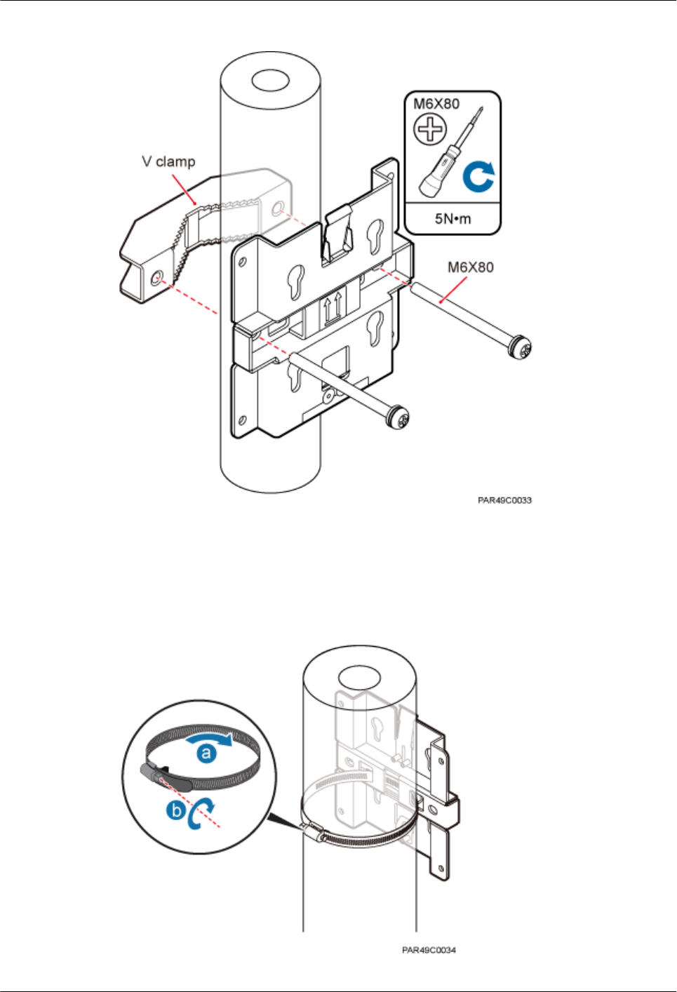
Figure 6-15 Securing the pRRU3901 installation kits on the metal pole
If the diameter of the pole is larger than 70 mm, use the hose clamp to install the plate on the
pole. The hose clamp is prepared by customers. Tighten the bolt with a torque of 5 N•m, as
shown in Figure 6-16.
Figure 6-16 Securing the pRRU3901 installation kits on the metal pole
LampSite
Installation Guide 6 Installing a pRRU3901
Issue 08 (2015-01-15) Huawei Proprietary and Confidential
Copyright © Huawei Technologies Co., Ltd.
67
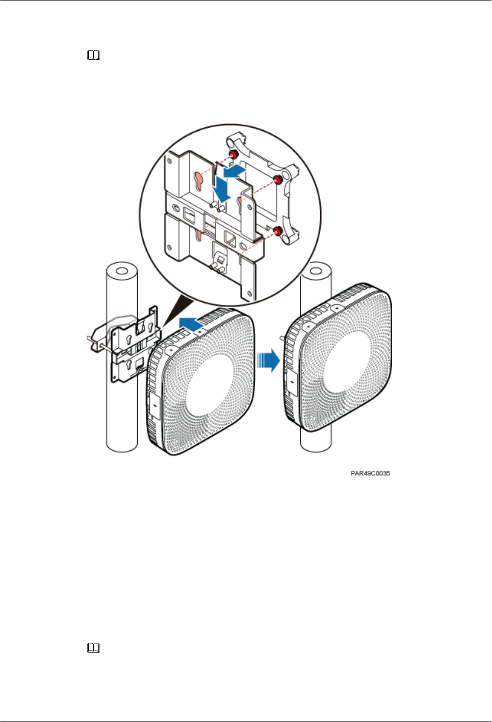
Step 3 Fit the four hooks of the pRRU3901 into the installation kits, as shown in Figure 6-17. If the
hooks are properly installed, a slight clack can be heard.
NOTE
It is recommended that you observe the installation from one side of the pRRU3901 when inserting hooks
into the kits.
Figure 6-17 Installing a pRRU3901
----End
6.4.5 pRRU3901 Installed on a Plate
If the plate on the ceiling has sufficient load bearing capacity and space installation, the
pRRU3901 can be installed on the plate of the ceiling indoors.
Procedure
Step 1 Determine the position for installing the pRRU3901 based on the construction blueprint and the
space requirements.
NOTE
For pRRU3901 installation space requirements, see Space Requirements.
Step 2 Place the plate in the installation position against the wall. Then, level the plate and mark the
two anchor points using a marker, as shown in Figure 6-18.
LampSite
Installation Guide 6 Installing a pRRU3901
Issue 08 (2015-01-15) Huawei Proprietary and Confidential
Copyright © Huawei Technologies Co., Ltd.
68
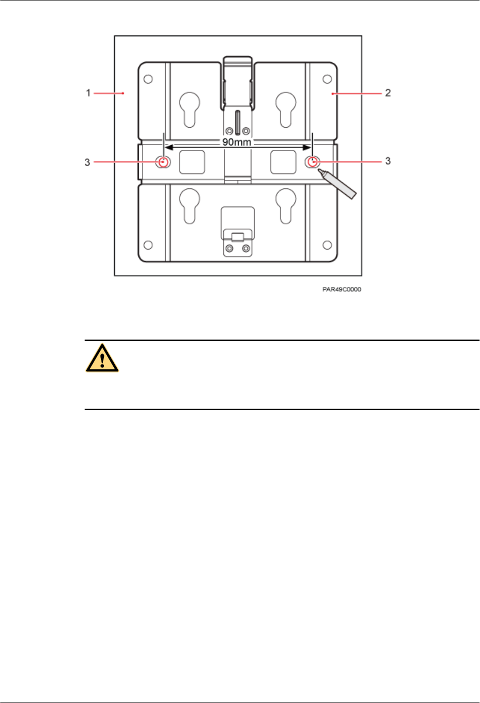
Figure 6-18 Anchor points of the pRRU3901 installation kits (unit: mm)
(1) Panel (2) Plate (3) Anchor point
CAUTION
To prevent inhalation or eye contact with dust, take adequate preventive measures when drilling
holes.
Step 3 Use a hammer drill with bit 8 to drill holes at the anchor points.
Step 4 Lead the bolt M6x80 through the panel and daughter board, and tighten the torque screwdriver
to a torque of 5 N•m, as shown in Figure 6-19.
LampSite
Installation Guide 6 Installing a pRRU3901
Issue 08 (2015-01-15) Huawei Proprietary and Confidential
Copyright © Huawei Technologies Co., Ltd.
69
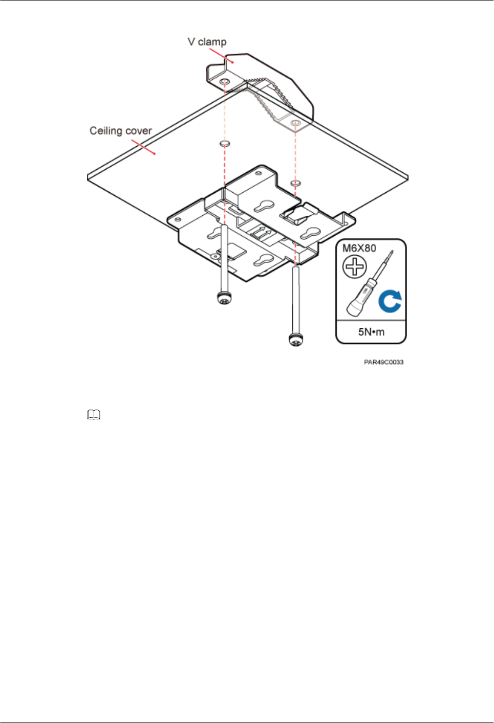
Figure 6-19 Installing the pRRU3901 installation kits
Step 5 Fit the four hooks of the pRRU3901 into the installation kits, as shown in Figure 6-20. If the
hooks are properly installed, a slight clack can be heard.
NOTE
It is recommended that you observe the installation from one side of the pRRU3901 when inserting hooks
into the kits.
LampSite
Installation Guide 6 Installing a pRRU3901
Issue 08 (2015-01-15) Huawei Proprietary and Confidential
Copyright © Huawei Technologies Co., Ltd.
70
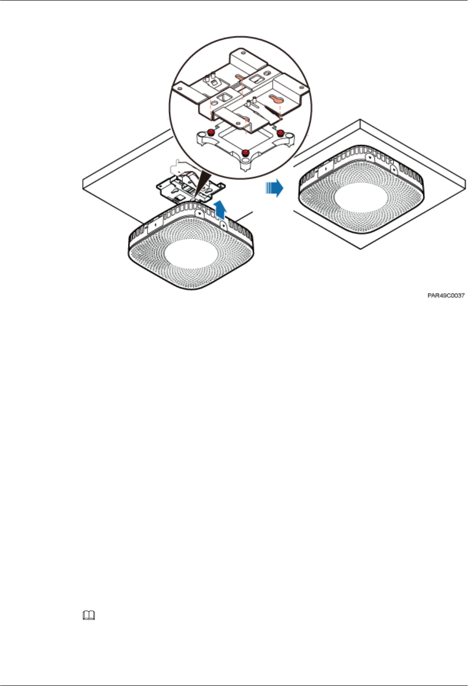
Figure 6-20 Installing a pRRU3901
----End
6.4.6 pRRU3901 Installed on a Keel
If the ceiling cover cannot bear the pRRU3901, the pRRU3901 can be installed on the keel of
a ceiling.
Context
Before installing the pRRU3901 on a keel, ensure that the keel is strong enough to bear the
pRRU3901.
lThe installation kits of the pRRU3901 can be installed on the keel of the following
specifications: GBT 11981-2008, JIS A6517-2002, and ASTM C635 C635M-2007. The
installation mode must depends on onsite requirements because there are various keels.
lThis section describes the procedure of installing a pRRU3901 on the keel of JIS standard
used in Japan. The procedure of installing a pRRU3901 on other keels is the same as that
of installing a pRRU3901 on the keel of JIS standard.
Procedure
Step 1 Determine the position for installing the pRRU3901 based on the construction blueprint and the
space requirements.
NOTE
For pRRU3901 installation space requirements, see Space Requirements.
Step 2 Lead the V clamp on across the keel, and mark the projective position on the cover with a marker,
as shown in Figure 6-21.
LampSite
Installation Guide 6 Installing a pRRU3901
Issue 08 (2015-01-15) Huawei Proprietary and Confidential
Copyright © Huawei Technologies Co., Ltd.
71
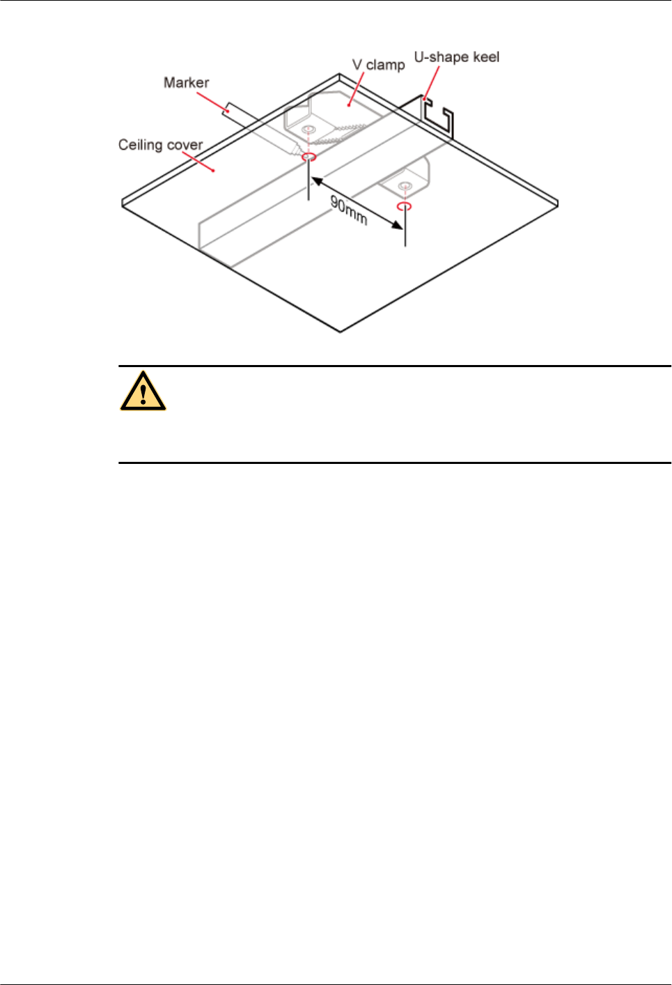
Figure 6-21 Anchor points on a plate (unit: mm)
CAUTION
To prevent inhalation or eye contact with dust, take adequate preventive measures when drilling
holes.
Step 3 Use a hammer drill to drill holes at the anchor points. You are advised to use the hammer drill
Ф12.
Step 4 Lead the bolt M6x80 through the installation plate and ceiling cover, and then socket to tighten
the bolt to a torque of 5 N•m, as shown in Figure 6-22.
LampSite
Installation Guide 6 Installing a pRRU3901
Issue 08 (2015-01-15) Huawei Proprietary and Confidential
Copyright © Huawei Technologies Co., Ltd.
72
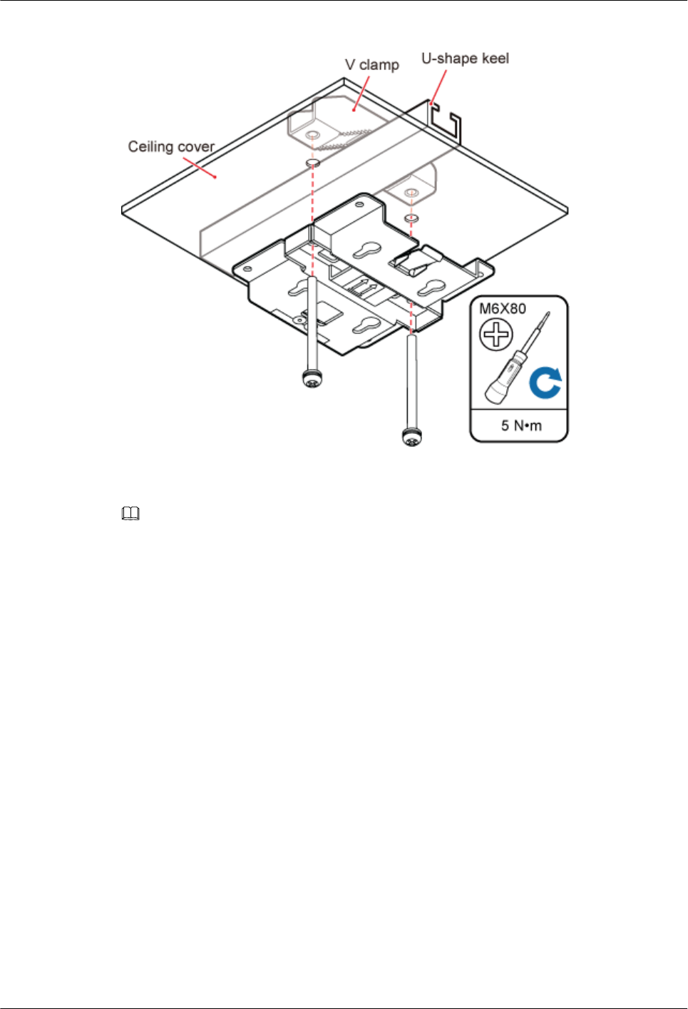
Figure 6-22 Installing the pRRU3901 installation kits
Step 5 Fit the four hooks of the pRRU3901 into the installation kits, as shown in Figure 6-23. If the
hooks are properly installed, a slight clack can be heard.
NOTE
It is recommended that you observe the installation from one side of the pRRU3901 when inserting hooks
into the kits.
LampSite
Installation Guide 6 Installing a pRRU3901
Issue 08 (2015-01-15) Huawei Proprietary and Confidential
Copyright © Huawei Technologies Co., Ltd.
73
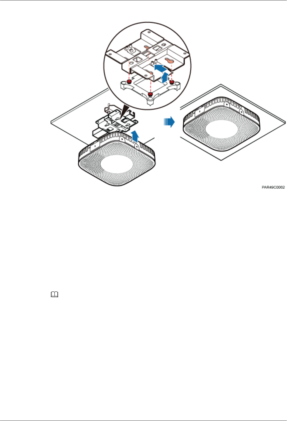
Figure 6-23 Installing a pRRU3901
----End
6.5 Installing pRRU3901 Cables
This section describes the procedure of installing the pRRU3901 cables.
6.5.1 Requirements for Cable Layout
Cables must be routed according to the specified cabling requirements to prevent signal
interference.
NOTE
If certain cables listed below are not required, skip the requirements for routing these cables.
General Requirements for Cable Layout
中国标准
l综合布线系统工程设计规范 GB 50311-2007
l综合布线工程验收规范(含条文说明) GB 50312-2007
l安全防范工程技术规范 GB 50348-2004
l电子信息系统机房施工及验收规范 GB 50462-2008
l智能建筑工程质量验收规范 GB 50339-2003
l建筑电气工程施工质量验收规范 GB 50303-2002
l通信管道工程施工及验收技术规范 GB 50374-2006
LampSite
Installation Guide 6 Installing a pRRU3901
Issue 08 (2015-01-15) Huawei Proprietary and Confidential
Copyright © Huawei Technologies Co., Ltd.
74

国际标准
l用户建筑综合布 ISO/IEC 11801
l商业建筑电信布线标准 EIA/TIA 568
l商业建筑电信布线安装标准 EIA/TIA 569
l商业建筑通信基础结构管理规范 EIA/TIA 606
l商业建筑通信接地要求 EIA/TIA 60
l信息系统通用布线标准 EN 50173
l信息系统布线安装标准 EN 50174
Bending radius
lThe bending radius of a 1/4'' jumper, a 1/2'' softer jumper, and a 1/2'' common jumper must
be longer than 35 mm, 50 mm, and 127 mm, respectively.
lThe bending radius of a power cable is at least three times the diameter of the cable.
lThe bending radius of a signal cable must be at least five times of the diameter of the cable.
Cable binding
lCables of the same type are bound together.
lDifferent types of cables must be separately routed with a minimum spacing of 30 mm and
cannot be entangled.
lThe cables are bound tightly and neatly and the sheaths of the cables is intact.
lThe cable ties face the same direction and all cable ties bound at similar positions must be
in a straight line.
lThe extra length of each indoor cable tie must be cut off. A slack of 5 mm is reserved for
each outdoor cable tie before the extra length is cut off. All cut surfaces are without sharp
edges.
lLabels or nameplates are attached to both ends, joints, or turns of cables after they are
installed.
Safety
lCables are placed away from sharp objects or wall burrs. If these positions are inevitable,
protection pipes are required for the cables.
lCables are routed away from heat sources, or heat-insulation materials are added between
cables and heat sources.
lA clearance is reserved at turns of a cable or the position close to a device, facilitating cable
and device maintenance. The recommended clearance is about 0.1 m.
Requirements for Special Cables
Ethernet Cable
lA maximum of 100 Ethernet cables can be bundled if no PVC pipes are used. If pipes are
used, a maximum of 24 Ethernet cables can be led through a pipe. In this case, ensure that
1/3 space inside the pipes must be vacant.
6.5.2 pRRU3901 Cable List
This section describes pRRU3901 cable connections.
LampSite
Installation Guide 6 Installing a pRRU3901
Issue 08 (2015-01-15) Huawei Proprietary and Confidential
Copyright © Huawei Technologies Co., Ltd.
75
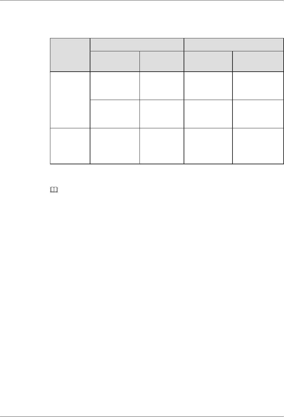
Table 6-7 lists pRRU3901 cables.
Table 6-7 List of pRRU3901 cables
Cable One End The Other End
Connector Connected
to ...
Connector Connected to ...
Ethernet
Cable
RJ45 connector RHUB3908/
CPRI_E0~CP
RI_E7 port
RJ45 connector pRRU3901/
CPRI_E0~CPRI_
E1 port
RJ45 connector AC or
Transmission
port
RJ45 connector pRRU3901/GE
port
(Optional)
pRRU3901
RF Jumper
SMA straight
male connector
External
antenna TX/
RX RF port on
the pRRU3901
Based on the port
model of the
antenna system.
Antenna system
NOTE
lThe Extender can be used to lengthen the distance between the RHUB3908 and the pRRU3901
connected using the Ethernet cable. If the Extender is used, the Ethernet cable is divided into two parts,
one between the RHUB3908 and the Extender and the other between the Extender and the pRRU3901.
lThe Ethernet cable used for connecting the GE port on the pRRU3901 to the AC transmission port is
required only when the pRRU3901 have three transmission ports and is configured with the Wi-Fi
daughter board.
6.5.3 Cable Connections
This section describes the cable connections for a single pRRU3901 and multiple pRRU3901s
in UMTS, LTE FDD, UMTS+LTE FDD, LTE FDD+LTE FDD mode.
Before installing the pRRU3901 cables, you must be aware of the following information:
lThe pRRU3901 can obtain power supply through the power over Ethernet (PoE).
lFor external antennas corresponding to RF daughter board 1, the TX port and RX port are
ANT0 and ANT1, respectively. For external antennas corresponding to RF daughter board
2, the TX port and RX port are ANT2 and ANT3, respectively. For external antennas
corresponding to RF daughter board 3, the TX port and RX port are ANT4 and ANT5,
respectively.
lThe external antenna system is optional, and the pRRU3901 jumpers are not delivered. By
default, the pRRU3901s are configured with built-in antennas. If the external antenna
system is connected, the antenna system automatically switches to the external one. One
end of the pRRU3901 RF jumper is the SMA male connector, which is connected to the
external antenna TX/RX RF port on the pRRU3901. The other end of the pRRU3901 RF
jumper is the type N male connector, which is connected to the antenna system. For the
standard of the pRRU3901 RF jumper, see (Optional) pRRU3901 RF Jumper of the
LampSite Hardware Description.
LampSite
Installation Guide 6 Installing a pRRU3901
Issue 08 (2015-01-15) Huawei Proprietary and Confidential
Copyright © Huawei Technologies Co., Ltd.
76
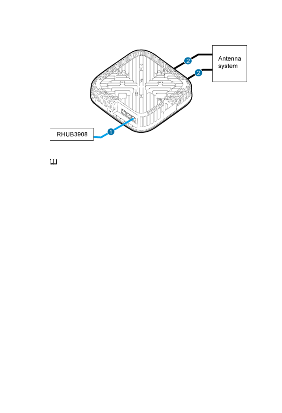
Figure 6-24 shows the cable connection when the pRRU3901 is configured with only one RF
Daughter Board.
Figure 6-24 pRRU3901 cable connection (1)
(1) Ethernet cable (2) RF jumper
NOTE
lThe Extender can be used to lengthen the distance between the RHUB3908 and the pRRU3901
connected using the Ethernet cable. If the Extender is used, the Ethernet cable is divided into two parts,
one between the RHUB3908 and the Extender and the other between the Extender and the pRRU3901.
lWhen two Ethernet cables are used to transmit CPRI signals, connect one end of the cables to the
CPRI_E0 and CPRI_E1 ports on the pRRU3901 panel and the other end to any two ports of CPRI_E0
to CPRI_E7 on the RHUB3908 panel. This document describes signal transmission using one Ethernet
cable as an example.
Figure 6-25 shows the cable connection when the pRRU3901 is configured with two RF
Daughter Boards.
LampSite
Installation Guide 6 Installing a pRRU3901
Issue 08 (2015-01-15) Huawei Proprietary and Confidential
Copyright © Huawei Technologies Co., Ltd.
77
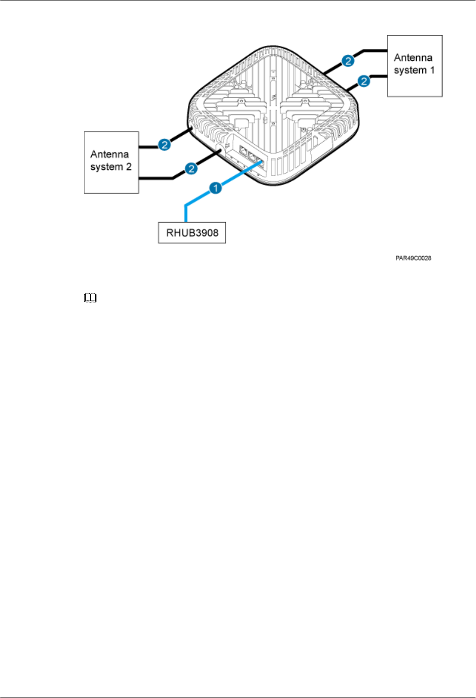
Figure 6-25 pRRU3901 cable connection (2)
(1) Ethernet cable (2) RF jumper
NOTE
lThe Extender can be used to lengthen the distance between the RHUB3908 and the pRRU3901
connected using the Ethernet cable. If the Extender is used, the Ethernet cable is divided into two parts,
one between the RHUB3908 and the Extender and the other between the Extender and the pRRU3901.
lWhen two Ethernet cables are used to transmit CPRI signals, connect one end of the cables to the
CPRI_E0 and CPRI_E1 ports on the pRRU3901 panel and the other end to any two ports of CPRI_E0
to CPRI_E7 on the RHUB3908 panel. This document describes signal transmission using one Ethernet
cable as an example.
Figure 6-26 shows the cable connection when the pRRU3901 is configured with two RF
Daughter Boards and one Wi-Fi daughter board.
LampSite
Installation Guide 6 Installing a pRRU3901
Issue 08 (2015-01-15) Huawei Proprietary and Confidential
Copyright © Huawei Technologies Co., Ltd.
78
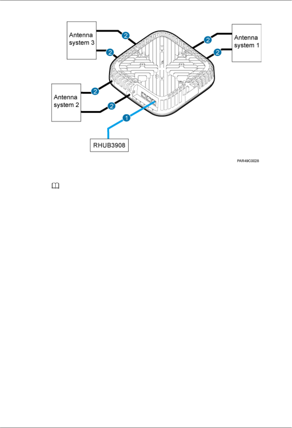
Figure 6-26 pRRU3901 cable connection (3)
(1) Ethernet cable (2) RF jumper
NOTE
lThe Extender can be used to lengthen the distance between the RHUB3908 and the pRRU3901
connected using the Ethernet cable. If the Extender is used, the Ethernet cable is divided into two parts,
one between the RHUB3908 and the Extender and the other between the Extender and the pRRU3901.
lWhen two Ethernet cables are used to transmit CPRI signals, connect one end of the cables to the
CPRI_E0 and CPRI_E1 ports on the pRRU3901 panel and the other end to any two ports of CPRI_E0
to CPRI_E7 on the RHUB3908 panel. This document describes signal transmission using one Ethernet
cable as an example.
6.5.4 Cable Connections (LTE TDD)
This section describes the cable connections for a single pRRU3901 and multiple pRRU3901s
in LTE TDD mode.
Before installing the pRRU3901 cables, you must be aware of the following information:
lThe pRRU3901 can obtain power supply through the power over Ethernet (PoE).
lFor external antennas corresponding to RF daughter board 1, the TX port and RX port are
ANT0 and ANT1, respectively. For external antennas corresponding to RF daughter board
2, the TX port and RX port are ANT2 and ANT3, respectively. For external antennas
corresponding to RF daughter board 3, the TX port and RX port are ANT4 and ANT5,
respectively.
lThe external antenna system is optional, and the pRRU3901 jumpers are not delivered. By
default, the pRRU3901s are configured with built-in antennas. If the external antenna
system is connected, the antenna system automatically switches to the external one. One
end of the pRRU3901 RF jumper is the SMA male connector, which is connected to the
external antenna TX/RX RF port on the pRRU3901. The other end of the pRRU3901 RF
jumper is the type N male connector, which is connected to the antenna system. For the
standard of the pRRU3901 RF jumper, please see (Optional) pRRU RF Jumper of the
LampSite Hardware Description.
LampSite
Installation Guide 6 Installing a pRRU3901
Issue 08 (2015-01-15) Huawei Proprietary and Confidential
Copyright © Huawei Technologies Co., Ltd.
79
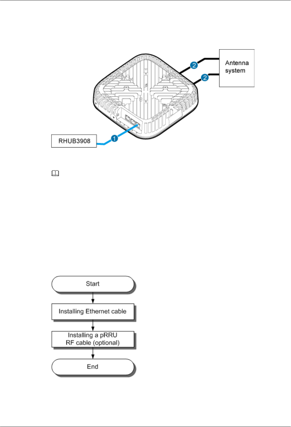
Figure 6-27 shows the cable connection when the pRRU3901 is configured with only one RF
Daughter Board.
Figure 6-27 pRRU3901 cable connection (1)
(1) Ethernet cable (2) RF jumper
NOTE
The Extender can be used to lengthen the distance between the RHUB and the pRRU connected using the
Ethernet cable. If the Extender is used, the Ethernet cable is divided into two parts, one between the RHUB
and the Extender and the other between the Extender and the pRRU.
6.5.5 pRRU3901 cable installation process
This section describes the process of installing pRRU3901 cables.
Figure 6-28 shows the process of installing pRRU3901 cables.
Figure 6-28 pRRU3901 cable installation process
6.5.6 Installing an Ethernet Cable
This section describes how to install an Ethernet cable.
LampSite
Installation Guide 6 Installing a pRRU3901
Issue 08 (2015-01-15) Huawei Proprietary and Confidential
Copyright © Huawei Technologies Co., Ltd.
80

Prerequisites
lEthernet cables are not delivered, and they must be prepared onsite. You need to use a
network cable tester to test the Ethernet cable connection.
lThe Ethernet cable must be of Category 5e (enhanced) or higher. In addition, its cross-
sectional area must be 24 AWG or larger and frame spread rating must be CM or higher.
With the internal PoE module providing power, the maximum length of an Ethernet cable
is 100 m. With the Extender, the distance of the pRRU3901 and RHUB3908 can be
extended by the Extender up to a total distance of 200 m.
Context
The Ethernet cable has the following functions:
lProvides power supply for the pRRU3901 when the cable connects the CPRI_E0 port on
the pRRU3901 to the RHUB.
lTransmits CPRI signals between an RHUB3908 and a pRRU3901.
lProvides Wi-Fi services for the pRRU3901 when the cable connects the GE port on the
pRRU3901 with three transmission ports to the AC.
Using the CPRI_E1 port on the pRRU3901 has the same Ethernet cable connection to the
RHUB3908 as using the CPRI_E0 port. The following section describes the connection using
the CPRI_E0 port.
Procedure
Step 1 Make the Ethernet cables.
1. Assemble an RJ45 connector and an Ethernet cable by following instructions in Assembling
the Unshielded RJ45 Connector and the Ethernet Cable of Installation Reference.
NOTE
Follow pin assignment instructions described in section Ethernet Cable in LampSite Hardware
Description to assemble the unshielded RJ45 connector and the Ethernet cable. Otherwise, the
transmission signal quality deteriorates and CPRI links may be disconnected.
2. Check whether the made RJ45 connector is qualified by following instructions in Checking
the Appearance of Metal Contact Strips.
3. To complete the assembly of the other end, repeat Step 1.1 and Step 1.2.
4. Check whether the touch points on the connectors at both ends are normally conducted and
well contacted and whether the connections are correct by following instructions in Testing
the Connection of Assembled Cables of Installation Reference.
Step 2 Install an Ethernet cable between an RHUB3908 and a pRRU3901.
1. Remove the dustproof cap of the CPRI_E0 port on the pRRU3901.
2. Connect the RJ45 connector at one end of the Ethernet cable to the CPRI_E0 port on the
pRRU3901 panel.
3. Optional: Connect the RJ45 connector at the other end of the Ethernet cable to the output
port of the Extender. Then, connect the RJ45 connector at one end of another Ethernet cable
to the input port of the Extender.
LampSite
Installation Guide 6 Installing a pRRU3901
Issue 08 (2015-01-15) Huawei Proprietary and Confidential
Copyright © Huawei Technologies Co., Ltd.
81
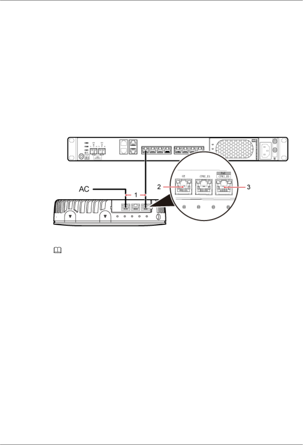
4. Connect the RJ45 connector at the other end of the Ethernet cable to any port ranging from
CPRI_E0 to CPRI_E7 on the RHUB3908 panel based on the engineering design, as shown
in Figure 6-29.
Step 3 Optional: Install the Ethernet cable between the pRRU3901 and the AC. This operation is
required when the pRRU3901 with three transmission ports is configured with a Wi-Fi daughter
board.
1. Remove the dustproof cap of the GE port on the pRRU3901.
2. Connect the RJ45 connector at one end of the Ethernet cable to the GE port on the
pRRU3901 panel.
3. Connect the RJ45 connector at the other end of the Ethernet cable to the transmission port
of the AC based on the engineering design, as shown in Figure 6-29.
Figure 6-29 Installing an Ethernet cable
(1) Ethernet cable (2) GE port on the pRRU3901 (3) CPRI_E0 port on the pRRU3901
NOTE
The pRRU3901 can have two transmission ports plus one PWR port or three transmission ports (plus one
PWR port or no PWR port), requiring the same installation operations. This section uses the pRRU3901
with three transmission ports no PWR port as an example.
----End
Follow-up Procedure
1. Route the cable, and then use a cable tie to bind the cable. For details, see 6.5.1
Requirements for Cable Layout.
2. Label the installed cable. For details, see section 8.3 Attaching an L-Shaped Label.
6.5.7 Installing pRRU3901 Jumpers (Optional)
pRRU3901 jumpers transmit radio frequency signals. One end of the jumper is the SMA straight
male connector, and the other end is the type N connector.
Context
lIf the RF jumper is provided by the customer, the jumper must not be lower than the RG316
specifications. In addition, the jumpers can be used after they are checked by Huawei
engineers.
LampSite
Installation Guide 6 Installing a pRRU3901
Issue 08 (2015-01-15) Huawei Proprietary and Confidential
Copyright © Huawei Technologies Co., Ltd.
82
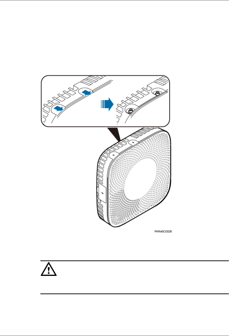
lpRRU3901s can be connected to external whip antennas or external remote antennas
(through pRRU3901 RF jumpers). Whip antennas are delivered optionally. RF jumpers are
not delivered.
Procedure
Step 1 Expose the SMA female connector by removing the pRRU3901 antenna housing, as shown in
Figure 6-30.
Figure 6-30 Removing the pRRU3901 antenna housing
Step 2 Use a torque wrench with a torque of 0.6 N•m to connect the SMA straight male connector on
a jumper to the ANT port on the pRRU3901 panel.
NOTICE
Tighten it with hands, and then use a torque wrench to tighten it with a rotational speed of less
than or equal to 2.4 rpm to tighten it.
Step 3 Connect the type N female connector of the jumper to the type N male connector of the RF feeder
connected to the built-in antenna.
LampSite
Installation Guide 6 Installing a pRRU3901
Issue 08 (2015-01-15) Huawei Proprietary and Confidential
Copyright © Huawei Technologies Co., Ltd.
83
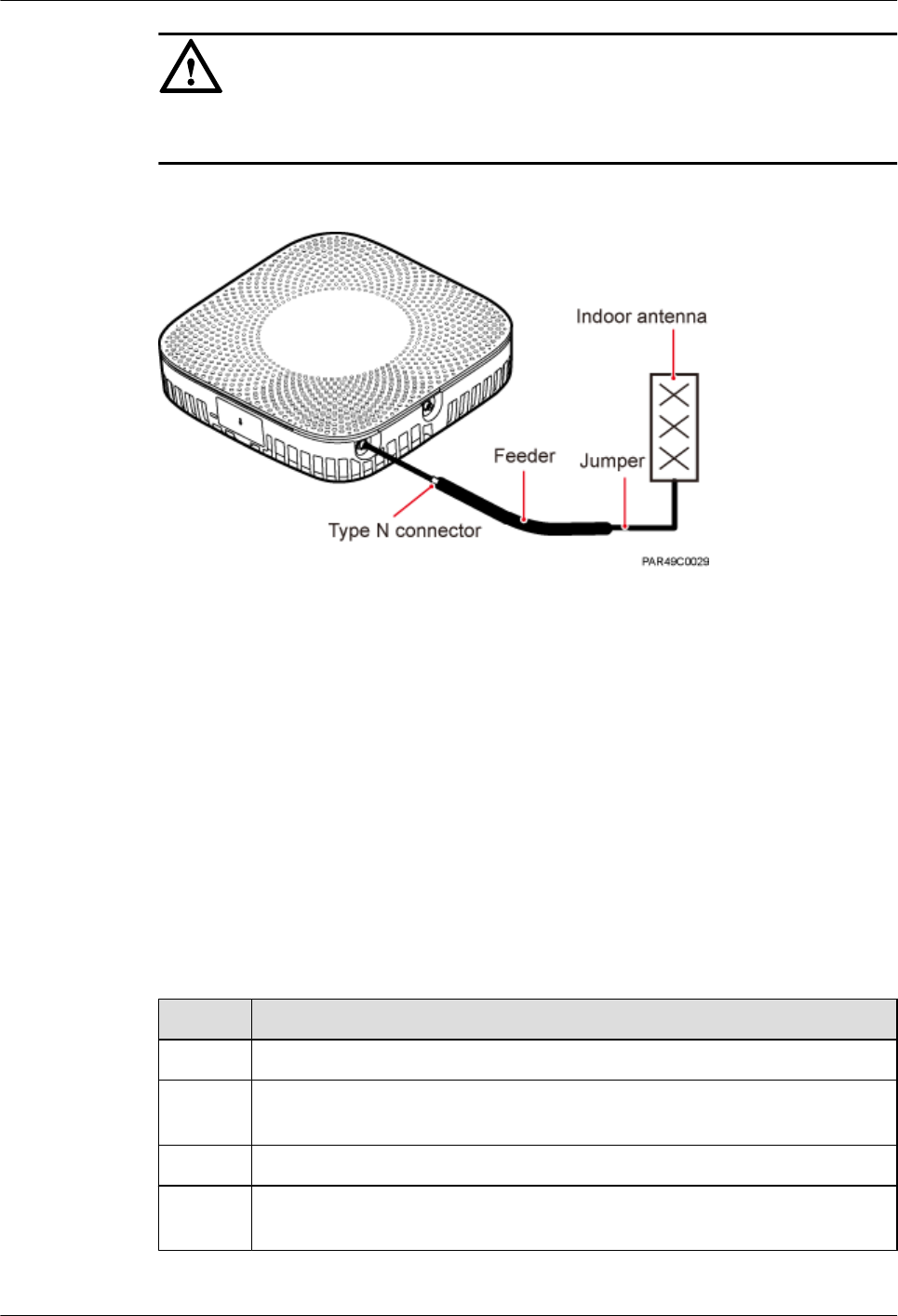
NOTICE
Tighten the feeder close to the type N connector to ensure that the jumper is not tightened. In
this way, the connectors on both ends of a jumper are not affected by the external force.
Figure 6-31 Installing jumpers between the pRRU3901 and external antennas
----End
Follow-up Procedure
1. Route the cable, and then use a cable tie to bind the cable. For details, see 6.5.1
Requirements for Cable Layout.
2. Label the installed cable. For details, see section 8.3 Attaching an L-Shaped Label.
6.6 Checking the pRRU3901 Hardware Installation
pRRU3901 hardware installation checking includes hardware and cable installation checking.
Table 6-8 lists the hardware installation checking items.
Table 6-8 Hardware installation checking list
No. Item
1Ensure that the pRRU3901 is not grouned.
2 The position for each device conforms to the engineering design and meets the
space requirement.
3 Ensure that the pRRU3901 is properly installed.
4 The surface of the pRRU3901 is neat and clean. The external paint is intact. The
labels, tags, and nameplates are correct, legible, and complete.
LampSite
Installation Guide 6 Installing a pRRU3901
Issue 08 (2015-01-15) Huawei Proprietary and Confidential
Copyright © Huawei Technologies Co., Ltd.
84
Table 6-9 lists the check items of the signal cable connection.
Table 6-9 Checklist for the signal cable connection
No. Item
1The connectors of the signal cables must securely connected.
2 The connectors of the signal cables are intact.
3 The signal cables are intact.
4 The cable ties are evenly spaced. The signal cables are bound neatly with cable
ties to proper tightness, and arranged at even intervals in the same direction.
5 The extra length of the cable ties is cut and removed. The cut surfaces of the indoor
cables are smooth and have no sharp edges.
6 The cable layout facilitates maintenance and expansion.
7 Correct and clear labels are attached to both ends of the signal cables.
Table 6-10 lists the checking items for other cable connections.
Table 6-10 Checklist for other cable connections
No. Item
1The connectors of the other cables must securely connected.
2 Labels on the cables are legible and bound based on the engineering requirements.
The cables must be bound tightly and neatly. The sheaths of the cables must not
be damaged.
3 Positions for routing the cables must meet requirements of the engineering design.
6.7 Powering on the pRRU3901
This section describes the power-on check on the pRRU3901 after the pRRU3901 hardware is
installed and checked.
Procedure
Step 1 Power on the pRRU3901.
The pRRU3901 can be powered in PoE mode. The RHUB3908 adopts the PoE power supply
to provide power for the pRRU3901 over the CPRI_E0 port.
Step 2 Power on the pRRU3901. Wait 3 to 5 minutes, check the status of the RUN indicator on the
pRRU3901.
LampSite
Installation Guide 6 Installing a pRRU3901
Issue 08 (2015-01-15) Huawei Proprietary and Confidential
Copyright © Huawei Technologies Co., Ltd.
85
If the RUN Indicator... Because... Then...
Steady on There is power input, but the
board is faulty.
Power off the power supply,
rectify the fault, and power on
the pRRU3901.
Steady off There is no power input, or an
alarm is reported on the board.
Power off the power supply
and check the power input. If
no fault is found after the
pRRU3901 is powered off,
clear the fault on the board, and
power on the pRRU3901.
On for 1s and off for 1s The device works properly. End this operation.
On for 0.125s and off for
0.125s
The software of the board is
loading.
Wait five minutes for the
software to be successfully
loaded. If the software is
loading five minutes later, shut
off the power supply. Check
whether the data configuration
file is correct. After the fault is
rectify, power on the
pRRU3901 again.
----End
LampSite
Installation Guide 6 Installing a pRRU3901
Issue 08 (2015-01-15) Huawei Proprietary and Confidential
Copyright © Huawei Technologies Co., Ltd.
86

7 Installing the Extender (Optional)
This section describes the Extender installation process.
Context
When an RHUB3908 and a pRRU need extended install, use extender. With the Extender, the
distance of the pRRU and RHUB3908 can be extended by the Extender up to a total distance of
200 m.
The Extender can be installed on a wall or ceiling in the same mode. This section describes wall-
mounted installation as an example.
Only space above and under the Extender is required to be reserved when installing the Extender.
The recommended space for installing the Extender is described as follows:
lAt least 150 mm above the Extender is reserved for cabling.
lAt least 150 mm under the Extender is reserved for cabling.
Procedure
Step 1 Use a marker to mark the two anchor points according to inter-hole spacing, as shown in Figure
7-1.
LampSite
Installation Guide 7 Installing the Extender (Optional)
Issue 08 (2015-01-15) Huawei Proprietary and Confidential
Copyright © Huawei Technologies Co., Ltd.
87
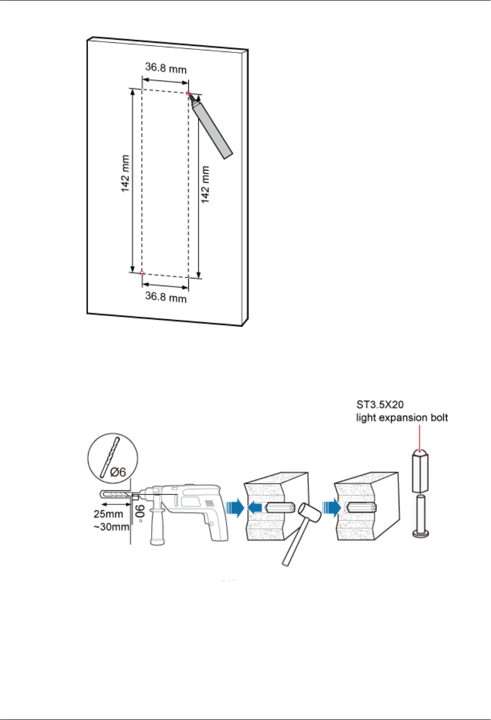
Figure 7-1 Marking anchor points
Step 2 Drill holes at the anchor points, and install expansion bolt assemblies, as shown in Figure 7-2.
The diameter of the hole is 6 mm, and the depth is 25 mm to 30 mm.
Figure 7-2 Drilling holes and installing expansion bolts
Step 3 Place the Extender in the corresponding position and use an M4 Phillips screwdriver to tighten
the screws to 1.4 N•m, as shown in Figure 7-3.
LampSite
Installation Guide 7 Installing the Extender (Optional)
Issue 08 (2015-01-15) Huawei Proprietary and Confidential
Copyright © Huawei Technologies Co., Ltd.
88
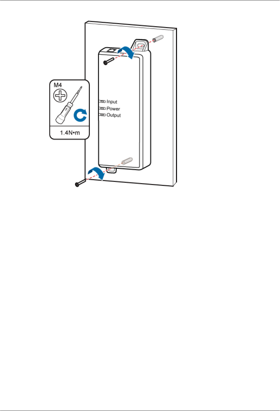
Figure 7-3 Installing Extender
----End
LampSite
Installation Guide 7 Installing the Extender (Optional)
Issue 08 (2015-01-15) Huawei Proprietary and Confidential
Copyright © Huawei Technologies Co., Ltd.
89

8 Appendix
About This Chapter
This chapter describes reference information during installation.
8.1 MAC Collection Template
This section describes the MAC collection template for a pRRU3901 with three transmission
ports.
8.2 LampSite Engineering Label
This section describes the content and presents the exterior of LampSite engineering labels.
8.3 Attaching an L-Shaped Label
This section describes the procedure and precautions to be taken for attaching an L-shaped label.
LampSite
Installation Guide 8 Appendix
Issue 08 (2015-01-15) Huawei Proprietary and Confidential
Copyright © Huawei Technologies Co., Ltd.
90
8.1 MAC Collection Template
This section describes the MAC collection template for a pRRU3901 with three transmission
ports.
The MAC collection template is used to record the installation position, MAC address of the
site at the initial installation stage to facilitate subsequent commissioning and maintenance.
Table 8-1 shows the MAC collection template.
Table 8-1 MAC collection template
No. Site
Number
Site Name WIFI MAC Location Information
Sampl
e
01 pRRU3901 xx floor, xx building, xx
mansion
Note: The MAC collection template is essential to the engineering stage and subsequent
maintenance, especially when multiple devices are installed at a short distance. This is
because the template defines the radio network to access. Maintain this template with
caution.
8.2 LampSite Engineering Label
This section describes the content and presents the exterior of LampSite engineering labels.
Label Content
The LampSite engineering labels include the RHUB3908 power label, RHUB3908 ground label,
RHUB3908 alarm or monitoring label, RHUB3908 optical transmission label, and RHUB3908
network transmission label, the pRRU3901 power label, pRRU3901 network transmission label,
pRRU3901 antenna label. The engineering labels are used for LampSite units RHUB3908 and
pRRU3901 for indoor scenarios.
LampSite
Installation Guide 8 Appendix
Issue 08 (2015-01-15) Huawei Proprietary and Confidential
Copyright © Huawei Technologies Co., Ltd.
91
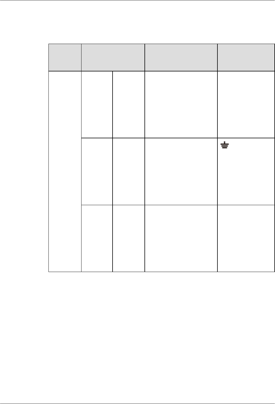
By default, blank labels are delivered for LampSite and must be filled in onsite. Table 8-2
describes the content of engineering labels.
Table 8-2 LampSite Engineering Label Content
NE Label Content Description Corresponding
port on the base
station
RHUB390
8
Power
label
RHUB390
8x
PWR
Label for the RHUB3908x
power cable.
x specifies the number of
RHUB3908s and cannot
exceed the maximum
RHUB3908 number
supported by the
networking.
PWR
Ground
label
RHUB390
8x
PGND
Label for the RHUB3908x
ground cable.
x specifies the number of
RHUB3908s and cannot
exceed the maximum
RHUB3908 number
supported by the
networking.
Alarm or
monitorin
g label
RHUB390
8x
EXT_AL
M
Label for the RHUB3908x
alarm cable.
x specifies the number of
RHUB3908s and cannot
exceed the maximum
RHUB3908 number
supported by the
networking.
EXT-ALM
LampSite
Installation Guide 8 Appendix
Issue 08 (2015-01-15) Huawei Proprietary and Confidential
Copyright © Huawei Technologies Co., Ltd.
92
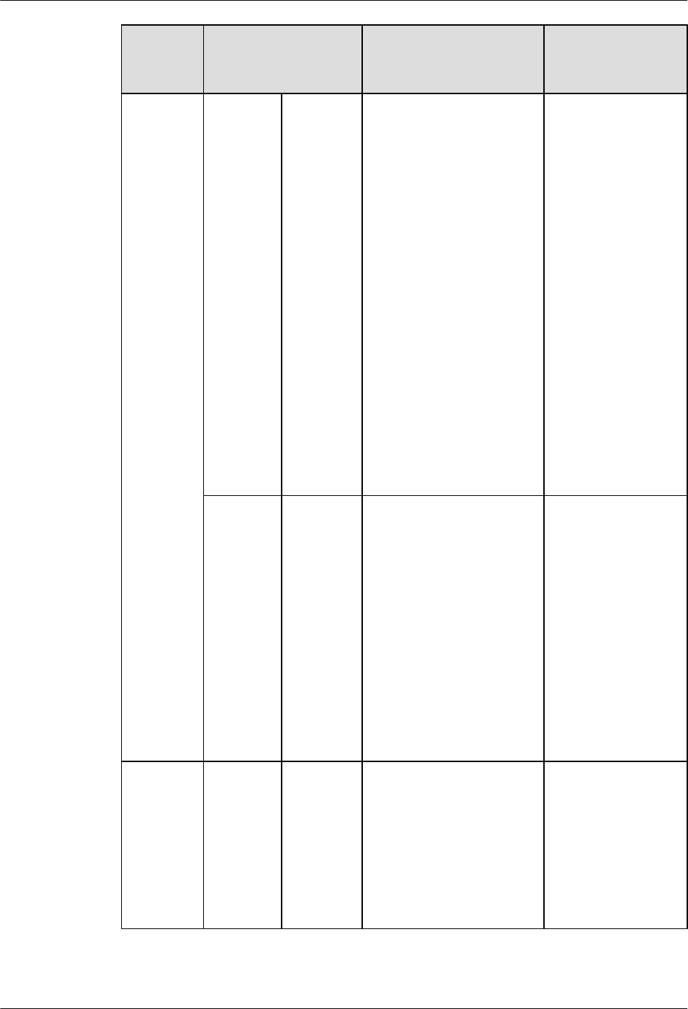
NE Label Content Description Corresponding
port on the base
station
Optical
transmissi
on label
RHUB390
8x
BBU/
RHUB390
8a/
RHUB390
8b
Label for the RHUB3908x
CPRI cable.
lx specifies the number of
RHUB3908s and cannot
exceed the maximum
RHUB3908 number
supported by the
networking.
la can be set to 0 or 1. 0
and 1 respectively
correspond to CPRI0
port and CPRI1 port of
the upper-level
RHUB3908.
lb can be set to 0 or 1. 0
and 1 respectively
correspond to CPRI0
port and CPRI1 port of
the lower-level
RHUB3908.
CPRI0 or CPRI1
Network
transmissi
on label
RHUB390
8x
CPRI_Ea
Label for the RHUB3908x
Ethernet cable.
lx specifies the number of
RHUB3908s and cannot
exceed the maximum
RHUB3908 number
supported by the
networking.
la can be set to 0 or 1. 0
and 1 respectively
correspond to CPRI_E0
port and CPRI_E1 port
of the pRRU3901.
CPRI_E0 to
CPRI_E7
pRRU390
1
Power
label
pRRU390
1y
PWR
Label for the pRRU3901y
power cable.
y specifies the number of
pRRU3901s and cannot
exceed the maximum
pRRU3901 number
supported by the
networking.
PWR or CPRI_E0
LampSite
Installation Guide 8 Appendix
Issue 08 (2015-01-15) Huawei Proprietary and Confidential
Copyright © Huawei Technologies Co., Ltd.
93
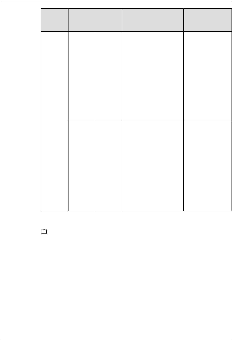
NE Label Content Description Corresponding
port on the base
station
Network
transmissi
on label
pRRU390
1y
CPRI_Ea
Label for the pRRU3901y
Ethernet cable.
ly specifies the number of
pRRU3901s and cannot
exceed the maximum
pRRU3901 number
supported by the
networking.
la can be set to 0 to 7,
which respectively
correspond to CPRI_E0
port to CPRI_E7 port of
the RHUB3908.
CPRI_E0 or
CPRI_E1
Antenna
label
pRRU390
1y
ANTa
Label for the pRRU3901y
RF Jumper.
ly specifies the number of
pRRU3901s and cannot
exceed the maximum
pRRU3901 number
supported by the
networking.
la can be set to 0 to 5,
which respectively
correspond to ANT0
port and ANT5 port of
the pRRU3901.
ANT0 to ANT5
NOTE
lIn the label, RHUB3908 and pRRU3901 identify the specific LampSite NEs.
lIf only one RHUB3908 is deployed, mark it as RHUB39080 on the label. If multiple RHUB3908s are
deployed, mark them in ascending sequence, beginning with RHUB39080.
lIf only one pRRU3901 is deployed, mark it as pRRU39010 on the label. If multiple pRRU3901s are
deployed, mark them in ascending sequence, beginning with pRRU39010.
lFor details about the maximum number of RHUB3908s and pRRU3901s in the LampSite solution, see
Typical Configurations in LampSite Technical Description.
Label Structure
Using the RHUB3908 power label as an example, Figure 8-1 shows the structure of a LampSite
engineering label.
LampSite
Installation Guide 8 Appendix
Issue 08 (2015-01-15) Huawei Proprietary and Confidential
Copyright © Huawei Technologies Co., Ltd.
94
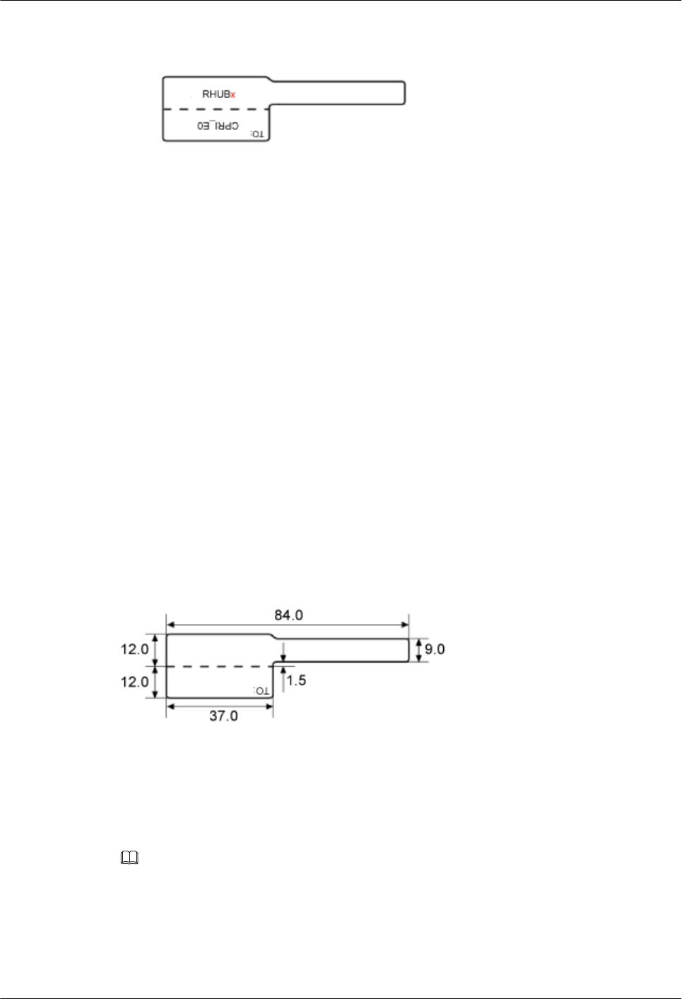
Figure 8-1 Label structure
8.3 Attaching an L-Shaped Label
This section describes the procedure and precautions to be taken for attaching an L-shaped label.
Context
lThis section applies to Huawei sign plate labels. If other engineering labels in accordance
with local standards are used on site, follow the local standards for attaching sign plate
labels.
lIn the LampSite solution, blank L-Shaped engineering labels are delivered by default.
lThe L-shaped label is usually used for the signal cable, E1/T1 cable, optical cable, and
power cable. The description in this section takes the Ethernet cable in a base station as an
example.
Procedure
Step 1 Obtain the engineering label to be attached from the whole set of the L-shaped engineering labels,
as shown in Figure 8-2.
Figure 8-2 Engineering label to be attached
Step 2 Attach the long end of the engineering label to the cable in the position 20 mm away from the
connector, and then turn over the long end along the adhesive face. Ensure that the edges of the
turned-over engineering label are in a line, as shown in Figure 8-3.
NOTE
By default, the label is attached in the position 20 mm away from the connector. If required, you can change
the position to make installation faster and more efficient. Consistency and neatness, however, must be
maintained.
Step 3 Adhere the long end to the labeling area. Ensure that the spacing between the cable and the
labeling area is 2 mm to 3 mm.
LampSite
Installation Guide 8 Appendix
Issue 08 (2015-01-15) Huawei Proprietary and Confidential
Copyright © Huawei Technologies Co., Ltd.
95
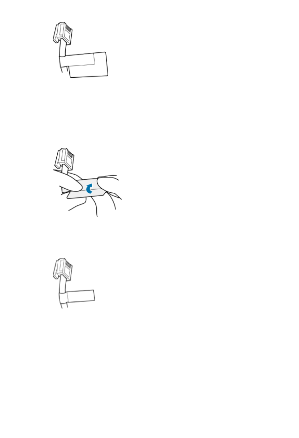
Figure 8-3 Adhering the long end to the labeling area
Step 4 Turn over the labeling area along the adhesive face from the bottom, and then finish attaching
the engineering label, as shown in Figure 8-4 and Figure 8-5. Ensure that the edges of the turned-
over labeling area are in a line.
Figure 8-4 Turning over the labeling area along the adhesive face
Figure 8-5 Attached engineering label
Step 5 Fill in the attached blank label by referring to 8.2 LampSite Engineering Label.
----End
LampSite
Installation Guide 8 Appendix
Issue 08 (2015-01-15) Huawei Proprietary and Confidential
Copyright © Huawei Technologies Co., Ltd.
96

pRRU3901, pRRU3901 AWS+PCS+WIFI
Issue: 02
Date: 2014.12.11
HUAWEI TECHNOLOGIES CO., LTD.

Issue (02)
Huawei Proprietary and Confidential
Copyright © Huawei Technologies Co., Ltd.
i
Copyright © Huawei Technologies Co., Ltd. 2010. All rights reserved.
No part of this document may be reproduced or transmitted in any form or by any means without prior
written consent of Huawei Technologies Co., Ltd.
Trademarks and Permissions
and other Huawei trademarks are trademarks of Huawei Technologies Co., Ltd.
All other trademarks and trade names mentioned in this document are the property of their respective
holders.
Notice
The purchased products, services and features are stipulated by the contract made between Huawei and
the customer. All or part of the products, services and features described in this document may not be
within the purchase scope or the usage scope. Unless otherwise specified in the contract, all statements,
information, and recommendations in this document are provided "AS IS" without warranties, guarantees or
representations of any kind, either express or implied.
The information in this document is subject to change without notice. Every effort has been made in the
preparation of this document to ensure accuracy of the contents, but all statements, information, and
recommendations in this document do not constitute the warranty of any kind, express or implied.
Huawei Technologies Co., Ltd.
Address:
Huawei Industrial Base
Bantian, Longgang
Shenzhen 518129
People's Republic of China
Website:
http://www.huawei.com
Email:
support@huawei.com

1 Safety
Issue (02)
Huawei Proprietary and Confidential
Copyright © Huawei Technologies Co., Ltd.
1-1
1 Safety
About This Chapter
1.1 Health and Safety
1.2 Equipment Safety
1.3 Electromagnetic Field exposure
1.1 Health and Safety
1.1.1 Overview
1.1.2 Electrical Safety
1.1.3 Inflammable Environment
cbb000002_1_41.1.4 Working at Heights
1.1.5 Mechanical Safety
1.1.6 Bundling Signal Cables
1.1.1 Overview
Introduction
This section describes the safety precautions you must take before installing or maintaining
Huawei equipment.
To ensure safety of humans and the equipment, pay attention to the safety symbols on the
equipment and all the safety instructions in this document.
The "NOTE", "CAUTION", and "WARNING" marks in other documents do not
represent all the safety instructions. They are only supplements to the safety instructions.
Installation and maintenance personnel must understand basic safety precautions to avoid
hazards.
When operating Huawei equipment, in addition to following the general precautions in
this document, follow the specific safety instructions given by Huawei.

1 Safety
1-2
Huawei Proprietary and Confidential
Copyright © Huawei Technologies Co., Ltd.
Issue (02)
Only trained and qualified personnel are allowed to install, operate, and maintain Huawei
equipment.
Local Safety Regulations
When operating Huawei equipment, you must follow the local laws and regulations. The
safety instructions in this document are only supplements to the local laws and regulations.
General Requirements
To minimize risk of personal injury and damage to equipment, read and follow all the
precautions in this document before performing any installation or maintenance.
Ensure that the instructions provided in this document are followed completely. This section
also provides guidelines for selecting the measuring and testing devices.
Installation
The device (or system) must be installed in an access-controlled location.
The device can be mounted only on concrete or non-combustible surfaces.
The device must be fixed securely on the floor or to other immovable objects such as
walls and mounting racks before operation.
When installing the unit, always make the ground connection first and disconnect it at
the end.
Tighten the thumbscrews by using a tool after initial installation and subsequent access
to the panel.
Ground
Do not damage the ground conductor or operate the device in the absence of a properly
installed ground conductor. Conduct the electrical inspection carefully.
The device (or system) must be connected permanently to the protection ground before
an operation. The cross-sectional area of the protective ground conductor must be at least
16 mm2.
Power Supply
For DC-supplied model: The device applies to DC power source that complies with the
Safety Extra-Low Voltage (SELV) requirements in IEC 60950-1 based safety standards.
Prepared conductors are connected to the terminal block, and only the appropriate
AWG/Type of wire is secured with the lug terminals.
Short-circuit (overcurrent) protection of the device varies according to the building's
installation. Ensure that a circuit breaker no larger than 125 VDC, 10 A (fuse) for DC
supplied model is used on the phase conductors (all current-carrying conductors).
For this device, a readily accessible disconnect device must be incorporated in the
building installation wiring.
Human Safety
Do not operate the device or cables during lightning strikes.
To avoid electric shock, do not connect safety extra-low voltage (SELV) circuits to
telecommunication network voltage (TNV) circuits.
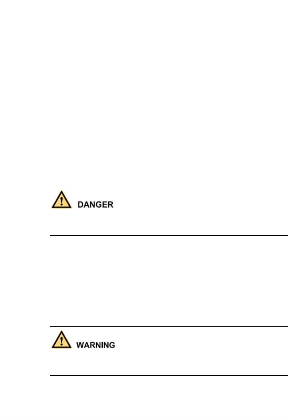
1 Safety
Issue (02)
Huawei Proprietary and Confidential
Copyright © Huawei Technologies Co., Ltd.
1-3
Move or lift the chassis by holding its lower edge. Do not hold the handles on certain
modules such as power supply, fans, and boards because they cannot support the weight
of the device.
Do not look into the optical port without eye protection.
Do not wear jewelry or watches when you operate the device.
Operator
Only qualified professional personnel are allowed to install, configure, operate, and
disassemble the device.
Only the personnel authenticated or authorized by Huawei are allowed to replace or
change the device of the parts of the device (including the software).
Any fault or error that might cause safety problems must be reported immediately to a
supervisor.
Only qualified personnel are allowed to remove or disable the safety facilities and to
troubleshoot and maintain the device.
1.1.2 Electrical Safety
High Voltage
The high voltage power supply provides power for the device operation. Direct or indirect
contact (through damp objects) with high voltage and AC mains supply may result in fatal
danger.
During the installation of the AC power supply facility, follow the local safety
regulations. The personnel who install the AC facility must be qualified to perform high
voltage and AC operations.
Do not wear conductive articles, such as watches, hand chains, bracelets, and rings
during the operation.
When water is found in the rack or the rack is damp, switch off the power supply
immediately.
When the operation is performed in a damp environment, make sure that the device is
dry.
Non-standard and improper high voltage operations may result in fire and electric shock.
Therefore, you must abide by the local rules and regulations when bridging and wiring AC
cables. Only qualified personnel are allowed to perform high voltage and AC operations.
1 Safety
1-4
Huawei Proprietary and Confidential
Copyright © Huawei Technologies Co., Ltd.
Issue (02)
Before powering on a device, ground the device. Otherwise, personal injury or device damage
may be caused by high leakage current.
Thunderstorm
Do not perform any operation, including high voltage and AC operations, on a steel tower or
mast during a thunderstorm.
Tools
Dedicated tools must be used during high voltage and AC operations. Avoid using ordinary
tools.
High Electrical Leakage
Ground the device before powering it on. Otherwise, personal injury or device damage may
be caused by high leakage current.
If a "high electrical leakage" tag is present on the power terminal of the device, you must
ground the device before powering it on.
Power Cable
Do not install or remove power cables when the device is on. Transient contact between the
core of the power cable and the conductor may generate electric arcs or sparks, which may
cause fire or hurt human eyes.
Before installing or removing the power cable, turn off the power switch.
Before connecting a power cable, check that the label on the power cable is correct.
1 Safety
Issue (02)
Huawei Proprietary and Confidential
Copyright © Huawei Technologies Co., Ltd.
1-5
If the device is connected with the DC power supply, use 16 mm² minimum power supply
cord.
Use type H03VV-F or light PVC-sheathed flexible cord according to IEC 60227.
1.1.3 Inflammable Environment
Operating the electrical device in an inflammable environment can be fatal.
Do not place the device in an environment that has inflammable and explosive air or gas. Do
not perform any operation in this environment.
.
1.1.4 Working at Heights
Avoid object falling when you work at heights.
When working at heights, fulfill the following requirements:
Only trained personnel can work at heights.
Prevent the devices and tools that you carry from falling down.
Take safety and protection measures, for example, wear a helm and safety belt.
Wear warm clothes when working at heights in a cold region.
Before working at heights, check that all the lifting facilities are in good condition.
Hoisting Heavy Objects
Do not walk below the cantilever or hoisted objects when heavy objects are being hoisted.
Only trained and qualified personnel can perform hoisting operations.
Before hoisting heavy objects, check that the hoisting tools are complete and in good
condition.
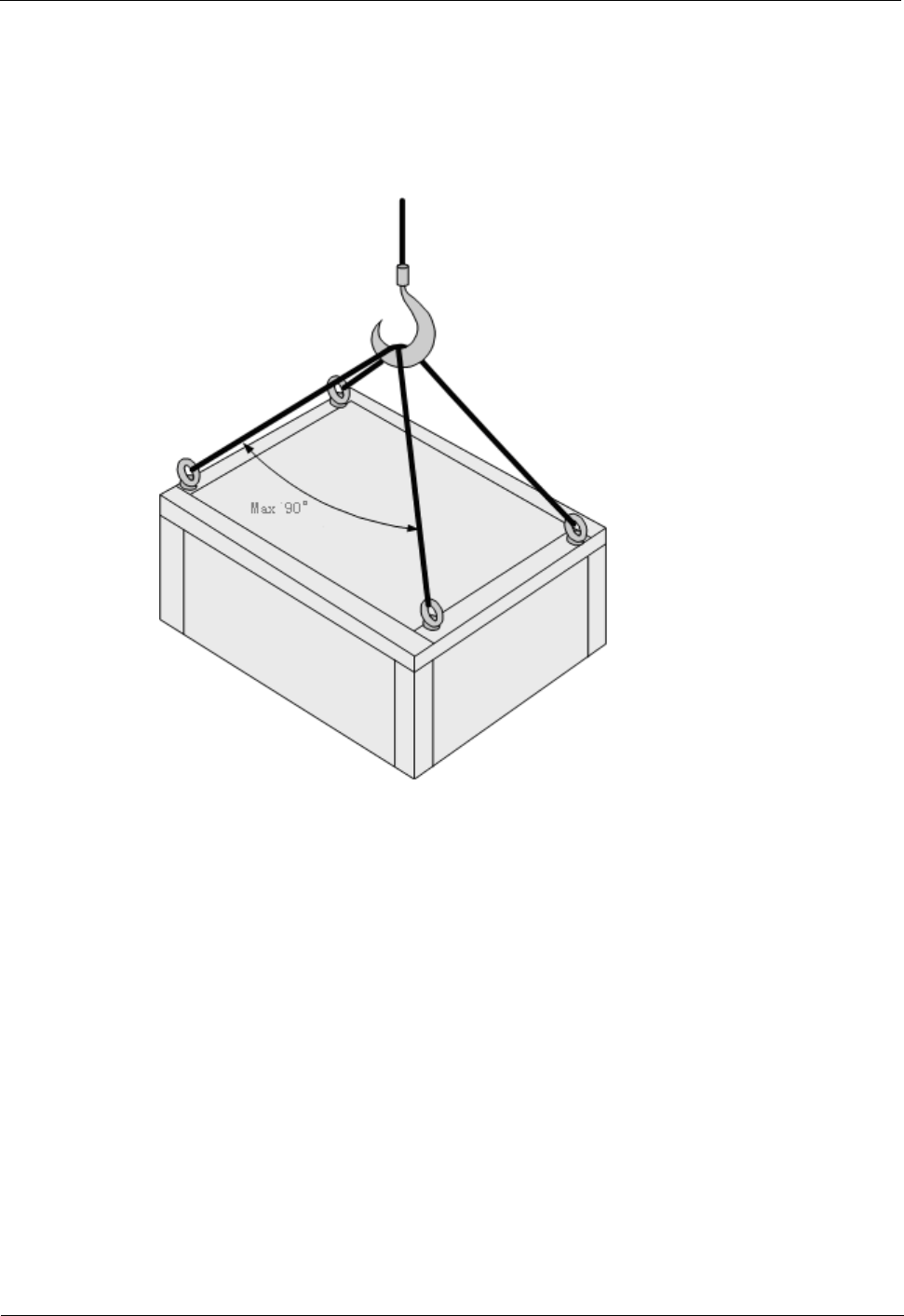
1 Safety
1-6
Huawei Proprietary and Confidential
Copyright © Huawei Technologies Co., Ltd.
Issue (02)
Before hoisting heavy objects, ensure that the hoisting tools are fixed to a secure object
or wall with good weight capacity.
Issue orders with short and explicit words to avoid misoperations.
Ensure that the angle formed by two cables is not larger than 90 degrees. See Figure 1-1.
Figure 1-1 Hoisting heavy objects
Using Ladders
Checking a Ladder
Before using a ladder, check whether the ladder is damaged. Only the ladder in good
condition can be used.
Before using a ladder, you should know the maximum weight capacity of the ladder.
Avoid overweighing the ladder.
Placing a Ladder
The recommended gradient of ladders is 75 degrees. You can measure the gradient of the
ladder with an angle square or your arms. When using a ladder, ensure that the wider feet of
the ladder are downward, or take protection measures for the ladder feet to prevent the ladder
from sliding. Ensure that the ladder is placed securely.
1 Safety
Issue (02)
Huawei Proprietary and Confidential
Copyright © Huawei Technologies Co., Ltd.
1-7
Climbing Up a Ladder
When climbing up a ladder, note the following:
Ensure that the center of gravity of your body does not deviate from the edges of the two
long sides.
To minimize the risk of falling, hold your balance on the ladder before any operation.
Do not climb higher than the fourth rung of the ladder (counted from up to down).
If you want to climb up a roof, ensure that the ladder top is at least one meter higher than
the roof.
1.1.5 Mechanical Safety
Drilling Holes
Do not drill the cabinet at will. Drilling holes without complying with the requirements affects
the electromagnetic shielding performance of the cabinet and damages the cables inside the
cabinet. In addition, if the scraps caused by drilling enter the cabinet, the printed circuit
boards (PCBs) may be short circuited.
Before you drill a hole in the cabinet, wear insulated gloves and remove the internal
cables from the cabinet.
Wear an eye protector when drilling holes. This is to prevent your eyes from being
injured by the splashing metal scraps.
Ensure that the scraps caused by drilling do not enter the cabinet.
Drilling holes without complying with the requirements affects the electromagnetic
shielding performance of the cabinet.
After drilling, clean the metal scraps immediately.
Sharp Objects
Before you hold or carry a device, wear protective gloves to avoid getting injured by sharp
edges of the device.
Lifting Heavy Objects
1 Safety
1-8
Huawei Proprietary and Confidential
Copyright © Huawei Technologies Co., Ltd.
Issue (02)
When heavy objects are being lifted, do not stand or walk under the cantilever or the lifted
object.
1.1.6Bundling Signal Cables
Do not bundle signal cables with high current cables or high voltage cables.
Maintain a minimum space of 150 mm between adjacent ties.
1.2 Equipment Safety
1.2.1 Electricity Safety
1.2.2 Electrostatic Discharge
1.2.3 Installing and Removing a Board
1.2.4 Laying Cables
1.2.1 Electricity Safety
Thunderstorm
During thunderstorms, the electromagnetic field generated in the thunderstorm area may
damage the electronic parts. To prevent damage to the device during lightning, ground the
device properly.
High Electrical Leakage
If the "high electrical leakage" tag is present on the power terminal of the device, you must
ground the device before powering it on.
1 Safety
Issue (02)
Huawei Proprietary and Confidential
Copyright © Huawei Technologies Co., Ltd.
1-9
Fuse
If a fuse is to be replaced, the new fuse must be of the same type and specifications.
Table 1-1 lists the fuses that affect the safety of the device (or system). Use fuses according to
this list.
Table 1-1 Fuse description
Position
Manufacturer
Type
Rating
Fuse
(F7000)on
pRRU3901
19040112
LITTELFUSE
INC
0451010.MRL
125VAC/DC,10 A
CONQUER
ELECTRONICS
CO LTD
SEF010
125VAC/DC,10 A
BEL FUSE INC
SSQ10
125VAC/86 VDC,
10 A
Fuse
(F7001)on
pRRU3901
19040110
LITTELFUSE
INC
0452004.MRL
125VAC/DC, 4 A
CONQUER
ELECTRONICS
CO LTD
SET004
125VAC, 32
VDC, 4 A
BEL FUSE INC
SST4
125VAC, 4 A
1.2.2Electrostatic Discharge
The static electricity generated by human bodies may damage the electrostatic-sensitive
components on boards, for example, the large-scale integrated (LSI) circuits.
Human body movement, friction between human bodies and clothes, friction between shoes
and floors, or handling of plastic articles causes static electromagnetic fields on human bodies.
These static electromagnetic fields cannot be eliminated until the static is discharged.
To prevent electrostatic-sensitive components from being damaged by the static on human
bodies, you must wear a well-grounded ESD wrist strap when touching the device or handling
boards or application-specific integrated circuits (ASICs).
Figure 1-2 shows how to wear an ESD wrist strap.
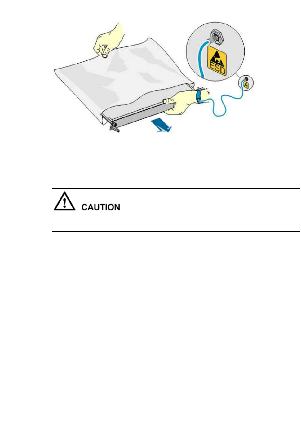
1 Safety
1-10
Huawei Proprietary and Confidential
Copyright © Huawei Technologies Co., Ltd.
Issue (02)
Figure 1-2 Wearing an ESD wrist strap
1.2.3 Installing and Removing a Board
When installing a board, use proper force to prevent the pins on the backplane from being
leaned.
When installing or removing a board, note the following:
Insert the board along the guide rails.
Prevent the surface of a board from contacting the surface of another board. This is to
prevent the boards from being short-circuited or scratched.
To prevent electrostatic-sensitive devices from being damaged by the ESD, do not touch
the circuits, components, connectors, or connection slots on boards.
1.2.4 Laying Cables
When the temperature is very low, violent strike or vibration may damage the cable sheathing.
To ensure safety, comply with the following requirements:
Cables can be laid or installed only when the temperature is higher than 0℃.
Before laying cables which have been stored in a temperature lower than 0℃, move the
cables to an environment of the ambient temperature and store them at the ambient
temperature for at least 24 hours.
Handle cables with caution, especially at a low temperature. Do not drop the cables
directly from the vehicle.

1 Safety
Issue (02)
Huawei Proprietary and Confidential
Copyright © Huawei Technologies Co., Ltd.
1-11
1.3 Electromagnetic Field Exposure
Introduction
The Base Transceiver Station (BTS) emits Radio Frequency (RF) radiation. Follow the local
safety regulations when installing and operating the BTS to avoid radiation hazard.
Location of Base Station Antennas
Base station antennas, the source of the radiation, are usually mounted:
On freestanding towers, with a height up to 30 m
On a tower on the top of buildings
To the side of buildings, on rare occasions
Generally, the antenna cannot be located in a position lower than 10 m. The energy usually
forms a horizontal main beam and is slightly tilted downwards. The remaining energy forms
into weaker beams on both sides of the main beam. The main beam, however, does not reach
the ground if the antenna is around 50–200 m away from the ground.
The highest level of emission would be expected in close vicinity of the antenna and in line of
sight to the antenna.
Exclusion Zones
The requirements for exclusion zones are as follows:
The antenna should be properly located to prevent the public from accessing the area
where the RF radiation exceeds the previously mentioned limits.
If areas with excessive RF radiation are accessible to the operation and maintenance
(O&M) personnel, ensure that they know the source of radiation and can power off or
shut down the transmitters before entering high radiation areas. In addition, such areas
must be confined within a distance of 10 m from the antennas.
Each exclusion zone should be defined by a physical barrier and by a recognizable sign
warning the public or O&M personnel.
Guidelines on Choosing Antenna Sites
The guidelines on choosing the antenna sites are as follows:
For roof-mounted antennas, raise the antennas above the height of the personnel who
may have to work on the rooftop.
For roof-mounted antennas, keep the transmitter antennas away from the areas accessible
to the public, such as roof access points, telephone service points, and HVAC devices.
For roof-mounted directional antennas, place the antennas near the periphery, and do not
make the antennas face the building.
Consider the trade-off between large aperture antennas (lower maximum RF) and small
aperture antennas (lower visual impact).
Keep higher-power antennas away from accessible areas.
Keep the antennas in a site that is far away from urban areas, though this may contradict
the coverage area requirements.

1 Safety
1-12
Huawei Proprietary and Confidential
Copyright © Huawei Technologies Co., Ltd.
Issue (02)
Exercise extra caution when designing co-location sites, that is, antennas owned by
different companies are located in the same site or are co-sited. This applies particularly
to sites that include high-power broadcast (FM/TV) antennas. Local zone often favors
co-location, but co-location may cause safety problems.
Take special precautions for antenna sites near hospital and schools.
Location of BTS
The BTS is shielded from RF radiation hazards. The device has been tested to comply with
the radioactive spurious emission requirements of international standards or local regulations.
Therefore, the BTS under normal operating conditions does not cause danger to the public and
O&M engineers. However, the limits for RF radiation might be exceeded due to faulty
antenna cables or for other causes.
BTS sites shall not be accessible to the public. Only authorized and trained personnel can
access BTS sites or equipment rooms.
A sign of excessive RF radiation must be present on the doors of the sites or equipment
rooms to warn the personnel inside the site or equipment room of excessive RF radiation.
BTS sites must be regularly monitored and inspected after installation.
Prediction of the Exposure to Electromagnetic Fields
This section provides a theoretical approach to calculate possible exposure to electromagnetic
radiation around a BTS antenna. Precise statements are possible either with measurements or
complex calculations considering the complexity of the environment, such as soil conditions,
nearby buildings and other obstacles. The complexity may cause reflection, deflection, and
scattering of electromagnetic fields.
The maximum output power (given in EIRP) of a BTS is usually limited by license conditions
of the network operator.
A rough estimation of the expected exposure in power flux density on a given point can be
made with the following equation:
S = (P(W) x Gnumeric)/(4 x r²(m) x π)
Where,
P = Maximum output power at antenna port of the BTS in W
Gnumeric = Numeric gain (see below)
r = Distance between the antenna and the point of exposure in meters
For the calculation of the Gnumeric,
Gnumeric = 10GdB/10
GdB = Gantenna(dB) – Bcable(dB) – Bvertical-attenutation(dB) – Bhorizontal-attenuation(dB)
B = attenuation in dB

LampSite
Site Maintenance Guide
Issue 05
Date 2015-01-15
HUAWEI TECHNOLOGIES CO., LTD.

Copyright © Huawei Technologies Co., Ltd. 2015. All rights reserved.
No part of this document may be reproduced or transmitted in any form or by any means without prior written
consent of Huawei Technologies Co., Ltd.
Trademarks and Permissions
and other Huawei trademarks are trademarks of Huawei Technologies Co., Ltd.
All other trademarks and trade names mentioned in this document are the property of their respective holders.
Notice
The purchased products, services and features are stipulated by the contract made between Huawei and the
customer. All or part of the products, services and features described in this document may not be within the
purchase scope or the usage scope. Unless otherwise specified in the contract, all statements, information,
and recommendations in this document are provided "AS IS" without warranties, guarantees or representations
of any kind, either express or implied.
The information in this document is subject to change without notice. Every effort has been made in the
preparation of this document to ensure accuracy of the contents, but all statements, information, and
recommendations in this document do not constitute a warranty of any kind, express or implied.
Huawei Technologies Co., Ltd.
Address: Huawei Industrial Base
Bantian, Longgang
Shenzhen 518129
People's Republic of China
Website: http://www.huawei.com
Email: support@huawei.com
Issue 05 (2015-01-15) Huawei Proprietary and Confidential
Copyright © Huawei Technologies Co., Ltd.
i
About This Document
Overview
This document describes routine maintenance items for a RHUB3908, pRRU3901, such as
equipment maintenance, and power-on and power-off operations. It also explains how to replace
the components and modules.
NOTE
For details of the BBU site maintenance guide, see DBS3900 Site Maintenance Guide.
Product Version
The following table lists the product version related to this document.
Product Name Solution Version Product Version
DBS3900 lSRAN9.0 and later versions
lRAN16.0 and later versions
leRAN7.0 and later versions
leRAN TDD 7.0 and later
versions
V100R009C00 and later versions
Intended Audience
This document is intended for:
lSystem engineers
lSite maintenance engineers
Organization
1 Changes in LampSite Site Maintenance Guide
LampSite
Site Maintenance Guide About This Document
Issue 05 (2015-01-15) Huawei Proprietary and Confidential
Copyright © Huawei Technologies Co., Ltd.
ii
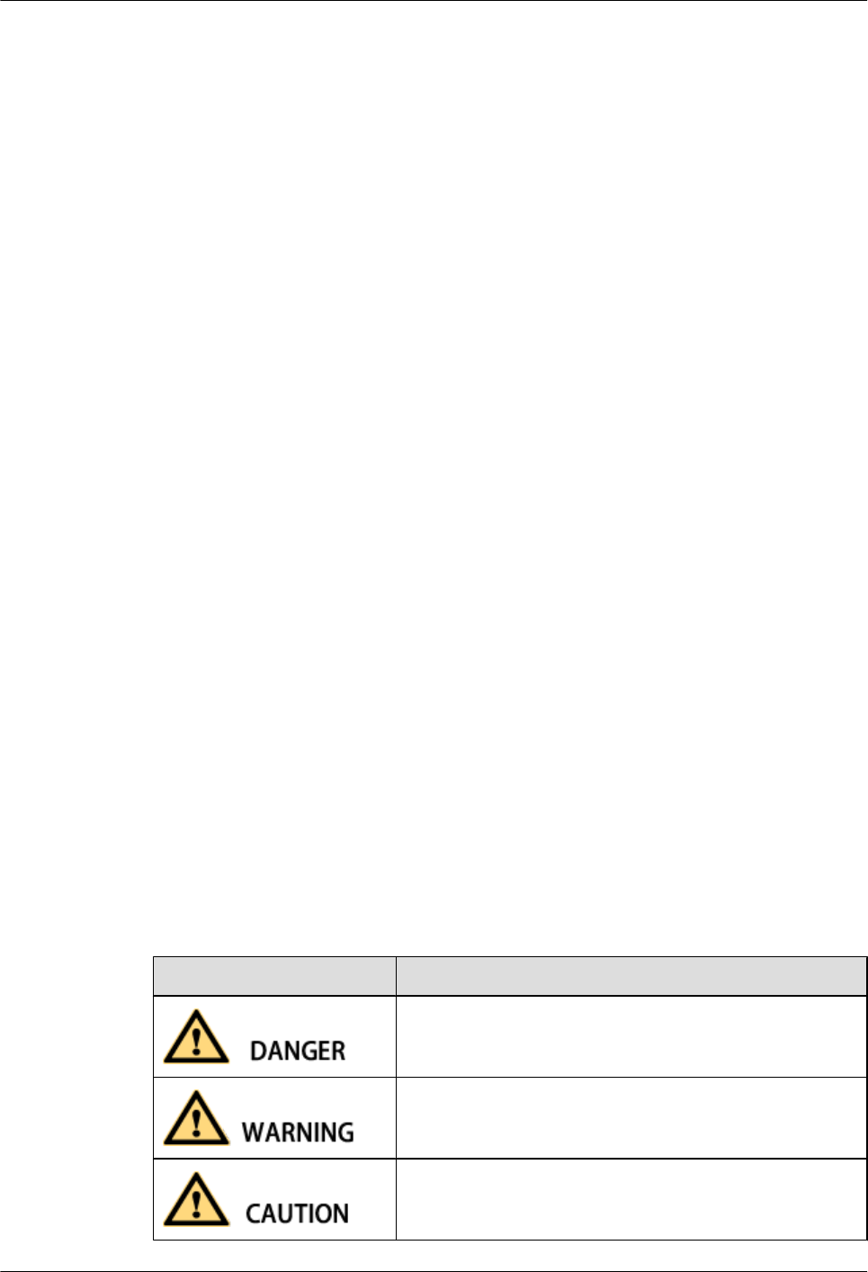
This chapter provides information about the changes in different document versions of
LampSite Site Maintenance Guide.
2 RHUB3908 Maintenance Items
This chapter describes the RHUB3908 maintenance items, involving the equipment room,
equipment, power system, and grounding system.
3 pRRU3901 Maintenance Items
This chapter describes the pRRU3901 maintenance items, involving equipment and power
system.
4 Powering On and Powering Off the RHUB3908
After the RHUB3908 is powered on, check the indicator status. Power off the RHUB3908 in
normal or emergency mode as required.
5 Powering On and Powering Off the pRRU3901
After the pRRU3901 is powered on, check the power supply voltage and indicator status. Power
off the pRRU3901 based on the power supply mode.
6 Replacing the RHUB3908
The RHUB3908 is an indoor convergence unit. It converges multiple pRRUs to the BBU3900.
Replacing the RHUB3908 interrupts services carried on the serving cell.
7 Replacing an Optical Module
An optical module provides a port for opto-electronic conversion. This enables the transmission
between the RHUB3908 and BBU3900 through the optical fiber. Replacing the optical module
requires removing the optical fibers. This interrupts all the services.
8 Replacing the pRRU3901
pRRU3901 is an indoor remote radio unit. It processes RF signals. Replacing the pRRU3901
interrupts all the services carried on it.
Conventions
Symbol Conventions
The symbols that may be found in this document are defined as follows.
Symbol Description
Indicates an imminently hazardous situation which, if not
avoided, will result in death or serious injury.
Indicates a potentially hazardous situation which, if not
avoided, could result in death or serious injury.
Indicates a potentially hazardous situation which, if not
avoided, may result in minor or moderate injury.
LampSite
Site Maintenance Guide About This Document
Issue 05 (2015-01-15) Huawei Proprietary and Confidential
Copyright © Huawei Technologies Co., Ltd.
iii
Symbol Description
Indicates a potentially hazardous situation which, if not
avoided, could result in equipment damage, data loss,
performance deterioration, or unanticipated results.
NOTICE is used to address practices not related to personal
injury.
Calls attention to important information, best practices and
tips.
NOTE is used to address information not related to personal
injury, equipment damage, and environment deterioration.
General Conventions
The general conventions that may be found in this document are defined as follows.
Convention Description
Times New Roman Normal paragraphs are in Times New Roman.
Boldface Names of files, directories, folders, and users are in
boldface. For example, log in as user root.
Italic Book titles are in italics.
Courier New Examples of information displayed on the screen are in
Courier New.
Command Conventions
The command conventions that may be found in this document are defined as follows.
Convention Description
Boldface The keywords of a command line are in boldface.
Italic Command arguments are in italics.
[ ] Items (keywords or arguments) in brackets [ ] are optional.
{ x | y | ... } Optional items are grouped in braces and separated by
vertical bars. One item is selected.
[ x | y | ... ] Optional items are grouped in brackets and separated by
vertical bars. One item is selected or no item is selected.
{ x | y | ... }*Optional items are grouped in braces and separated by
vertical bars. A minimum of one item or a maximum of all
items can be selected.
LampSite
Site Maintenance Guide About This Document
Issue 05 (2015-01-15) Huawei Proprietary and Confidential
Copyright © Huawei Technologies Co., Ltd.
iv
Convention Description
[ x | y | ... ]*Optional items are grouped in brackets and separated by
vertical bars. Several items or no item can be selected.
GUI Conventions
The GUI conventions that may be found in this document are defined as follows.
Convention Description
Boldface Buttons, menus, parameters, tabs, window, and dialog titles
are in boldface. For example, click OK.
>Multi-level menus are in boldface and separated by the ">"
signs. For example, choose File > Create > Folder.
Keyboard Operations
The keyboard operations that may be found in this document are defined as follows.
Format Description
Key Press the key. For example, press Enter and press Tab.
Key 1+Key 2 Press the keys concurrently. For example, pressing Ctrl+Alt
+A means the three keys should be pressed concurrently.
Key 1, Key 2 Press the keys in turn. For example, pressing Alt, A means
the two keys should be pressed in turn.
Mouse Operations
The mouse operations that may be found in this document are defined as follows.
Action Description
Click Select and release the primary mouse button without moving
the pointer.
Double-click Press the primary mouse button twice continuously and
quickly without moving the pointer.
Drag Press and hold the primary mouse button and move the
pointer to a certain position.
LampSite
Site Maintenance Guide About This Document
Issue 05 (2015-01-15) Huawei Proprietary and Confidential
Copyright © Huawei Technologies Co., Ltd.
v

Contents
About This Document.....................................................................................................................ii
1 Changes in LampSite Site Maintenance Guide.......................................................................1
2 RHUB3908 Maintenance Items...................................................................................................5
3 pRRU3901 Maintenance Items....................................................................................................9
4 Powering On and Powering Off the RHUB3908...................................................................11
4.1 Powering On the RHUB3908.......................................................................................................................................12
4.2 Powering Off the RHUB3908......................................................................................................................................13
5 Powering On and Powering Off the pRRU3901....................................................................14
5.1 Powering On the pRRU3901........................................................................................................................................15
5.2 Powering Off the pRRU3901.......................................................................................................................................16
6 Replacing the RHUB3908...........................................................................................................17
7 Replacing an Optical Module...................................................................................................21
8 Replacing the pRRU3901............................................................................................................25
LampSite
Site Maintenance Guide Contents
Issue 05 (2015-01-15) Huawei Proprietary and Confidential
Copyright © Huawei Technologies Co., Ltd.
vi
1 Changes in LampSite Site Maintenance
Guide
This chapter provides information about the changes in different document versions of
LampSite Site Maintenance Guide.
05 (2015-01-15)
This is the fifth commercial release.
Compared with 04 (2014-07-30), this issue includes the following new topic:
l8 Replacing the pRRU3901
Compared with 04 (2014-07-30), this issue incorporates the following changes:
Content Change Description
Entire document lChanged RHUB, and pRRU to
RHUB3908, and pRRU3901,
respectively.
lAdded the pRRU3901 with three
transmission ports plus no PWR port (or
the pRRU3901a for use in North
America) .
5 Powering On and Powering Off the
pRRU3901
Deleted the description that the pRRU3901
supports AC/DC power supply.
Compared with 04 (2014-07-30), no information is deleted.
04 (2014-07-30)
This is the fourth commercial release.
Compared with 03 (2014-06-30), no information is added.
Compared with 03 (2014-06-30), this issue incorporates the following change:
LampSite
Site Maintenance Guide 1 Changes in LampSite Site Maintenance Guide
Issue 05 (2015-01-15) Huawei Proprietary and Confidential
Copyright © Huawei Technologies Co., Ltd.
1
Content Change Description
Replacing an Optical Module Modified the steps of replacing an Optical
Module.
Compared with 03 (2014-06-30), no information is deleted.
03 (2014-06-30)
This is the third commercial release.
Compared with 02 (2014-05-30), no information is added.
Compared with 02 (2014-05-30), this issue incorporates the following changes:
Content Change Description
Replacing the RF Daughter Board Added descriptions about the block type
supported in the LampSite solution.
Replacing the pDock Mother Board
Replacing the Wi-Fi Daughter Board
Compared with 02 (2014-05-30), no information is deleted.
02 (2014-05-30)
This is the second commercial release.
Compared with 01 (2014-04-26), no information is added.
Compared with 01 (2014-04-26), this issue incorporates the following change:
Content Change Description
Entire document Added the descriptions about the LTE FDD
+LTE FDD mode.
Compared with 01 (2014-04-26), no information is deleted.
01 (2014-04-26)
This is the first commercial release.
Compared with Draft C (2014-03-26), no information is added.
Compared with Draft C (2014-03-26), this issue incorporates the following changes:
LampSite
Site Maintenance Guide 1 Changes in LampSite Site Maintenance Guide
Issue 05 (2015-01-15) Huawei Proprietary and Confidential
Copyright © Huawei Technologies Co., Ltd.
2
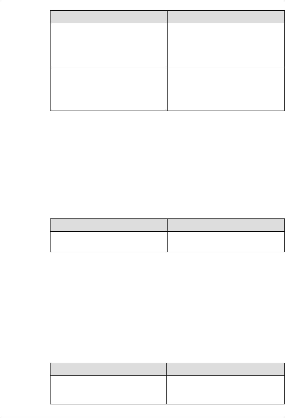
Content Change Description
Entire document Changed the pRRU3901 name from
pRRU3901 with two Ethernet ports to
pRRU3901 with two transmission ports, and
pRRU3901 with three Ethernet ports to
pRRU3901 with three transmission ports.
Replacing the pDock Mother Board Changed the pDock name from pDock with
two Ethernet ports to pDock with two
transmission ports, and pDock with three
Ethernet ports to pDock with three
transmission ports.
Compared with Draft C (2014-03-26), this issue excludes the following topic:
lReplacing a PSU
Draft C (2014-03-26)
This is a draft release.
Compared with Draft B (2014-02-28), no information is added.
Compared with Draft B (2014-02-28), this issue incorporates the following change:
Content Change Description
Replacing the RHUB Deleted the operation of resetting the
RHUB3908 after replacing.
Compared with Draft B (2014-02-28), no information is deleted.
Draft B (2014-02-28)
This is a draft release.
Compared with draft A (2013-11-30), this issue includes the following new topic:
lReplacing the Wi-Fi Daughter Board
Compared with draft A (2013-11-30), this issue incorporates the following changes:
Content Change Description
Entire document Added descriptions about pRRU3901s with
three transmission ports. Such pRRU3901s
support integrated Wi-Fi services.
LampSite
Site Maintenance Guide 1 Changes in LampSite Site Maintenance Guide
Issue 05 (2015-01-15) Huawei Proprietary and Confidential
Copyright © Huawei Technologies Co., Ltd.
3

Content Change Description
Added the descriptions about the UMTS, LTE
FDD and UMTS+LTE FDD mode.
LampSite Site Maintenance Guide Optimized descriptions about matching
product versions.
Replacing the RF Daughter Board Added the procedures for removing and
attaching labels.
Replacing the Wi-Fi Daughter Board
Compared with draft A (2013-11-30), this issue excludes the following topic:
lReplacing the pRRU3901
Draft A (2013-11-30)
This is a draft release.
LampSite
Site Maintenance Guide 1 Changes in LampSite Site Maintenance Guide
Issue 05 (2015-01-15) Huawei Proprietary and Confidential
Copyright © Huawei Technologies Co., Ltd.
4

2 RHUB3908 Maintenance Items
This chapter describes the RHUB3908 maintenance items, involving the equipment room,
equipment, power system, and grounding system.
Equipment Room Maintenance Items
Table 2-1 lists the equipment room maintenance items.
Table 2-1 Equipment room maintenance items
Item Check Frequency Operation Reference
Standard
Environment alarms
in the equipment
room
Daily Check whether any
power alarm, fire
alarm, or smoke
alarm is reported.
No power alarm, fire
alarm, or smoke
alarm is reported.
Temperature in the
equipment room
Each time
maintenance is
performed
Record temperatures
in the equipment
room measured by a
thermometer.
-5°C to +50°C
Humidity in the
equipment room
Each time
maintenance is
performed
Record humidity in
the equipment room
measured by a
hygrometer.
5%RH to 95%RH
Lighting system in
the equipment room
Every other month Check whether the
routine lighting
system and
emergency lighting
system are running
properly.
-
Air conditioner Every other month Check whether the
air conditioner is
running properly.
-
LampSite
Site Maintenance Guide 2 RHUB3908 Maintenance Items
Issue 05 (2015-01-15) Huawei Proprietary and Confidential
Copyright © Huawei Technologies Co., Ltd.
5
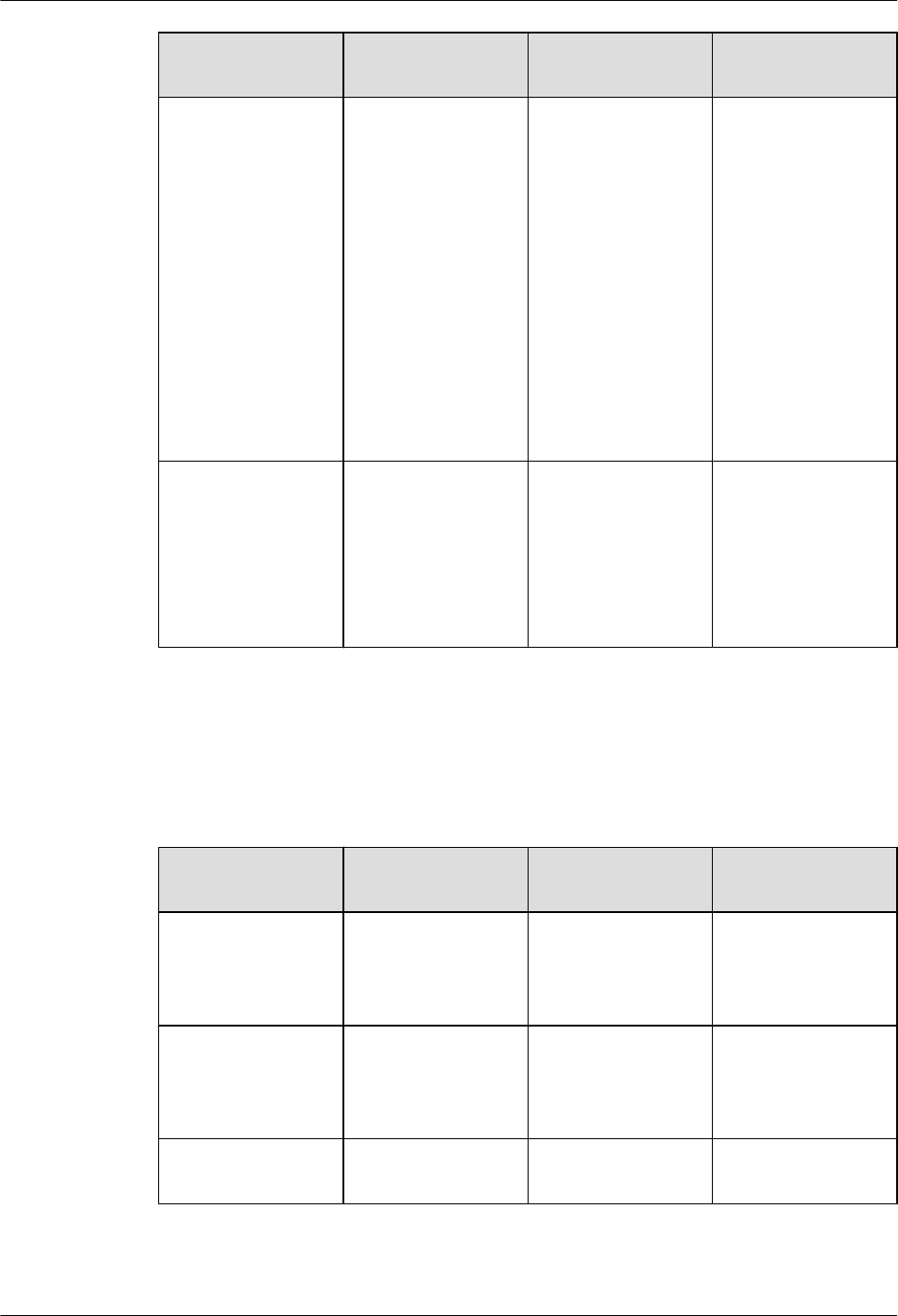
Item Check Frequency Operation Reference
Standard
Disaster protection
devices
Every one month Check whether the
disaster protection,
equipment
protection, and
firefighting devices
are normal.
lThe equipment
room is equipped
with portable
foam-type
extinguishers,
and the pressure
and expiration
date must be
checked.
lThe equipment
room has no
mice, ants, flying
insects, or other
risks.
Cleanness Every one month Check whether the
cabinet, equipment
housing, equipment
interior, desktop,
floor, door, and
window are clean
and tidy.
All these items are
clean and tidy.
Equipment Maintenance Items
Table 2-2 lists the equipment maintenance items.
Table 2-2 Equipment maintenance items
Item Check Frequency Operation Reference
Standard
Fan in the PSU Monthly or quarterly Check whether the
fan is working
properly.
The fan works
properly without any
abnormal smell or
sound.
Equipment surface Monthly or quarterly Check whether the
equipment surface is
intact.
The equipment
surface is intact and
the label of the
cabinet is legible.
Equipment cleanness Monthly or quarterly Check whether the
equipment is clean.
The equipment
surface is clean.
LampSite
Site Maintenance Guide 2 RHUB3908 Maintenance Items
Issue 05 (2015-01-15) Huawei Proprietary and Confidential
Copyright © Huawei Technologies Co., Ltd.
6
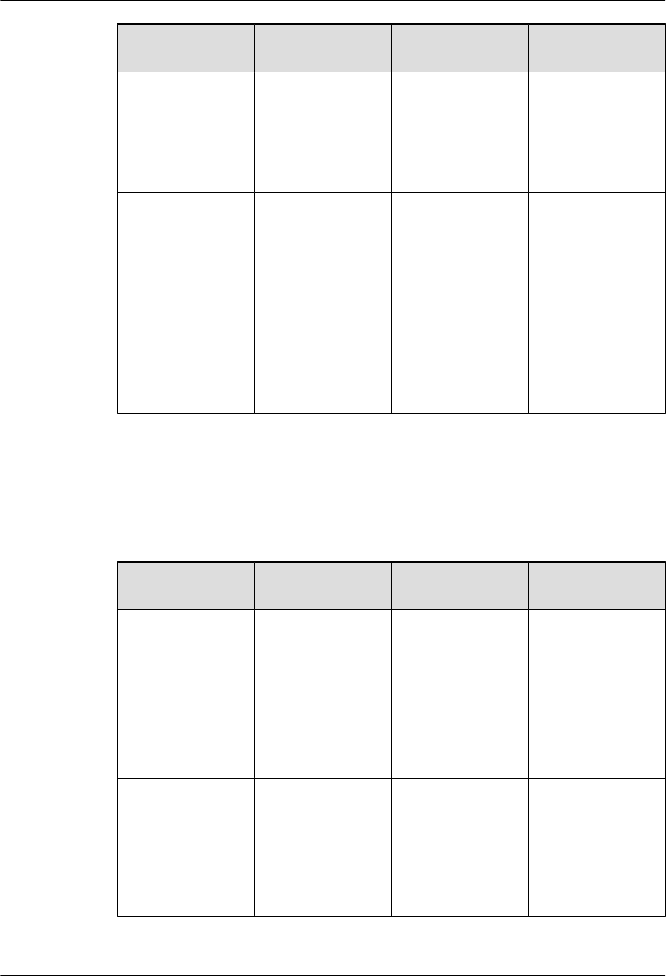
Item Check Frequency Operation Reference
Standard
Indicators Monthly or quarterly Check whether the
indicators on the
equipment are
working properly.
For details about the
indicator status, see
RHUB3908 Ports
and Indicators in
LampSite Hardware
Description.
Electrostatic
discharge (ESD)
wrist strap
Quarterly Check the ESD wrist
strap in either of the
following ways:
lUse an ESD wrist
strap tester to
check the ESD
wrist strap.
lUse a multimeter
to test the ground
resistance of the
ESD wrist strap.
If you use an ESD
wrist strap tester, the
GOOD indicator is
on. If you use a
multimeter, the
ground resistance of
the ESD wrist strap
ranges from 0.75
ohms to 10 ohms.
Maintenance Items for the Power System and Grounding System
Table 2-3 lists the maintenance items for the power system and grounding system.
Table 2-3 Maintenance items for the power system and grounding system
Item Check Frequency Operation Reference
Standard
Power cables Monthly or quarterly Check the power
cable connections.
The power cables are
securely connected
and not deteriorating.
The joints are not
corroded.
Voltage Monthly or quarterly Use a multimeter to
measure the voltage
of the power supply.
The voltage is in the
permissible range.
PGND cables Monthly or quarterly Checks whether the
PGND cables and
ground bar are
securely connected.
The joints are secure
and not corroded.
The PGND cables
and ground bar are
not deteriorated and
are protected from
corrosion.
LampSite
Site Maintenance Guide 2 RHUB3908 Maintenance Items
Issue 05 (2015-01-15) Huawei Proprietary and Confidential
Copyright © Huawei Technologies Co., Ltd.
7

Item Check Frequency Operation Reference
Standard
Ground resistance Monthly or quarterly Use a ground
resistance tester to
measure the ground
resistance and record
the measurement
result.
The ground
resistance is equal to
or less than 10 ohms.
LampSite
Site Maintenance Guide 2 RHUB3908 Maintenance Items
Issue 05 (2015-01-15) Huawei Proprietary and Confidential
Copyright © Huawei Technologies Co., Ltd.
8
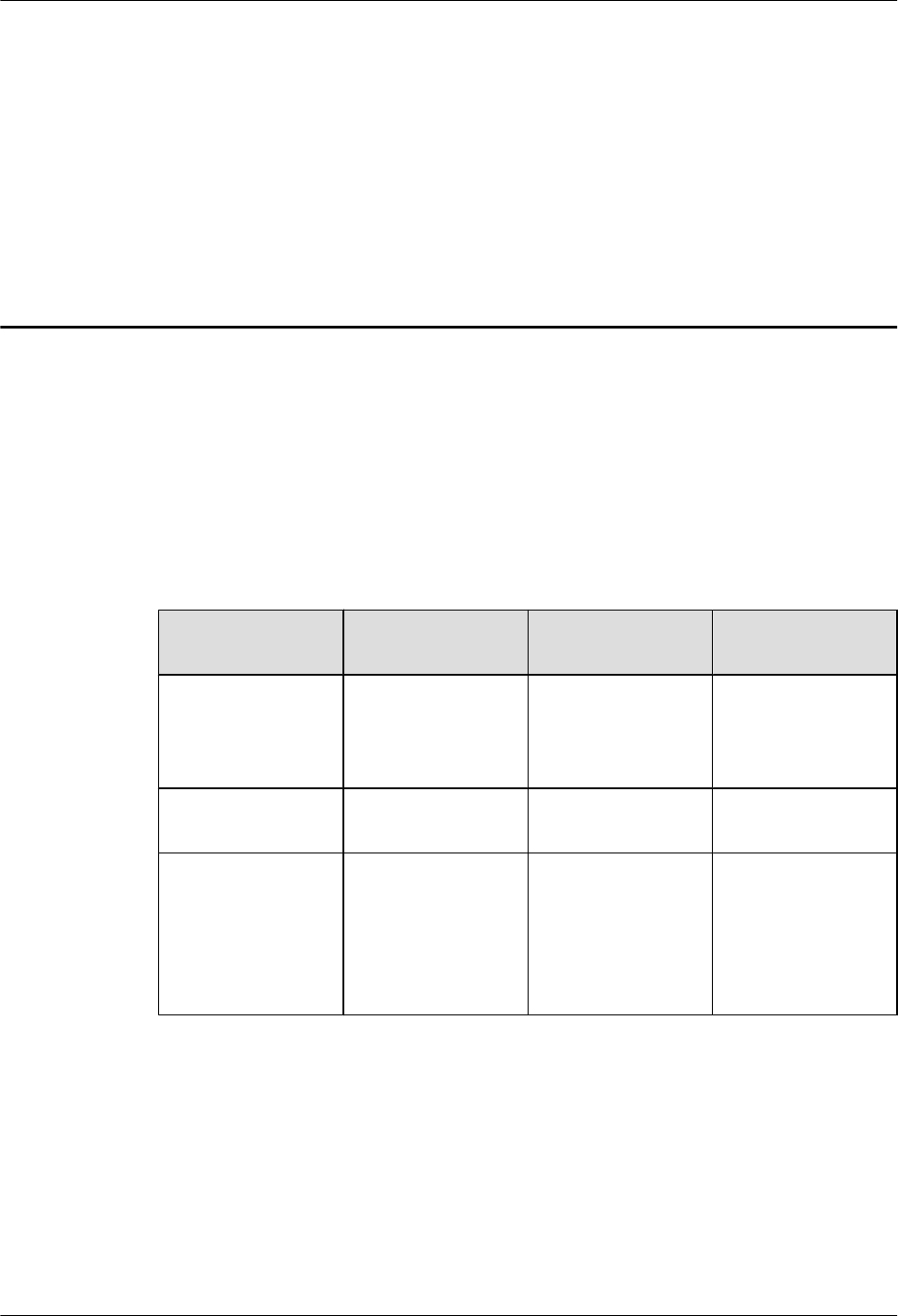
3 pRRU3901 Maintenance Items
This chapter describes the pRRU3901 maintenance items, involving equipment and power
system.
Equipment Maintenance Items
Table 3-1 lists the equipment maintenance items for the pRRU3901.
Table 3-1 Equipment maintenance items
Item Check Frequency Operation Reference
Standard
Equipment surface Monthly or quarterly Check whether the
equipment surface is
intact.
The equipment
surface is intact and
the label of the
cabinet is legible.
Equipment cleanness Monthly or quarterly Check whether the
equipment is clean.
The equipment
surface is clean.
Indicators Monthly or quarterly Check whether the
indicators on the
equipment are
working properly.
For details about the
indicator status, see
pRRU3901 Ports and
Indicators in
LampSite Hardware
Description.
Power System Maintenance Items
Table 3-2 lists the power system maintenance items for the pRRU3901.
LampSite
Site Maintenance Guide 3 pRRU3901 Maintenance Items
Issue 05 (2015-01-15) Huawei Proprietary and Confidential
Copyright © Huawei Technologies Co., Ltd.
9

Table 3-2 Power system maintenance items
Item Check Frequency Operation Reference
Standard
Power cables Monthly or quarterly Check the power
cable connections.
The power cables are
securely connected
and not deteriorating.
The joints are not
corroded.
Voltage Monthly or quarterly Use a multimeter to
measure the voltage
of the power supply.
The voltage is in the
permissible range.
LampSite
Site Maintenance Guide 3 pRRU3901 Maintenance Items
Issue 05 (2015-01-15) Huawei Proprietary and Confidential
Copyright © Huawei Technologies Co., Ltd.
10

4 Powering On and Powering Off the
RHUB3908
About This Chapter
After the RHUB3908 is powered on, check the indicator status. Power off the RHUB3908 in
normal or emergency mode as required.
4.1 Powering On the RHUB3908
The RHUB3908 is powered by AC input.
4.2 Powering Off the RHUB3908
An RHUB3908 can be powered off in two ways: normal power-off and emergency power-off.
You need to perform a normal power-off in scenarios such as an equipment swap or foreseeable
regional blackout, and you need to perform an emergency power-off in emergencies such as a
fire, smoke, or water damage in indoor scenarios.
LampSite
Site Maintenance Guide 4 Powering On and Powering Off the RHUB3908
Issue 05 (2015-01-15) Huawei Proprietary and Confidential
Copyright © Huawei Technologies Co., Ltd.
11
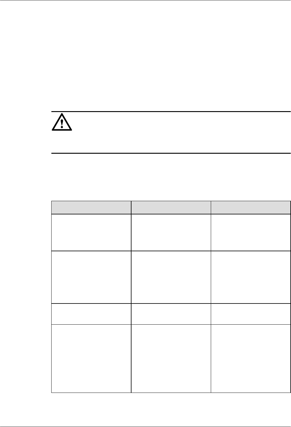
4.1 Powering On the RHUB3908
The RHUB3908 is powered by AC input.
Prerequisites
The power cable of the RHUB3908 is not connected to power, that is, the power plug is removed.
Context
NOTICE
The RHUB3908 must be powered on within 7 days after it is unpacked, and the period of its
power-off state cannot exceed 7 days during maintenance.
Procedure
Step 1 Insert the power plug to power on the RHUB3908.
Step 2 Wait 3 to 5 minutes. Then check the status of the RUN indicator.
If the RUN Indicator Is... It Indicates that... Then...
Steady on There is power input, but the
board is faulty.
Disable the power supply,
rectify the board fault, and
then power on the
RHUB3908 again.
Steady off There is no power input, or an
alarm about the board is
reported.
Disable the power supply and
check the power input again.
If the power input is normal,
rectify the board fault, and
then power on the
RHUB3908 again.
1s on and 1s off The RHUB3908 is running
properly.
End the power-on check task.
0.125s on and 0.125s off The board software is being
loaded.
If the loading is not complete
after 5 minutes, disable the
power supply and check
whether the data in the
configuration file is correct.
Rectify the fault and then
power on the RHUB3908
again.
----End
LampSite
Site Maintenance Guide 4 Powering On and Powering Off the RHUB3908
Issue 05 (2015-01-15) Huawei Proprietary and Confidential
Copyright © Huawei Technologies Co., Ltd.
12
4.2 Powering Off the RHUB3908
An RHUB3908 can be powered off in two ways: normal power-off and emergency power-off.
You need to perform a normal power-off in scenarios such as an equipment swap or foreseeable
regional blackout, and you need to perform an emergency power-off in emergencies such as a
fire, smoke, or water damage in indoor scenarios.
Procedure
lNormal power-off
NOTICE
Powering off the RHUB3908 interrupts services, and therefore perform associated
operations before a power-off.
1. Remove the power plug to disconnect the RHUB3908 with the external power input.
2. If the RHUB3908 is equipped with an external power device, turn off the switch of
the external power device.
lEmergency power-off
1. Turn off the switch of the external power device.
----End
LampSite
Site Maintenance Guide 4 Powering On and Powering Off the RHUB3908
Issue 05 (2015-01-15) Huawei Proprietary and Confidential
Copyright © Huawei Technologies Co., Ltd.
13

5 Powering On and Powering Off the
pRRU3901
About This Chapter
After the pRRU3901 is powered on, check the power supply voltage and indicator status. Power
off the pRRU3901 based on the power supply mode.
5.1 Powering On the pRRU3901
After the pRRU3901 is powered on, check its running status by observing the indicator status.
5.2 Powering Off the pRRU3901
A pRRU3901 can be powered off in two ways: normal power-off and emergency power-off.
You need to perform a normal power-off in scenarios such as an equipment swap or foreseeable
regional blackout, and you need to perform an emergency power-off in emergencies such as a
fire, smoke, or water damage in indoor scenarios.
LampSite
Site Maintenance Guide 5 Powering On and Powering Off the pRRU3901
Issue 05 (2015-01-15) Huawei Proprietary and Confidential
Copyright © Huawei Technologies Co., Ltd.
14
5.1 Powering On the pRRU3901
After the pRRU3901 is powered on, check its running status by observing the indicator status.
Prerequisites
The pRRU3901 and the cables are correctly installed.
Context
NOTICE
The pRRU3901 must be powered on within 7 days after it is unpacked, and the period of its
power-off state cannot exceed 7 days during maintenance.
Procedure
Step 1 Power on the pRRU3901.
The pRRU3901 can be powered in PoE mode. The RHUB3908 adopts the PoE power supply
to provide power for the pRRU3901 over the CPRI_E0 port.
Step 2 Wait 3 to 5 minutes. Then Check the status of the RUN indicator.
If the RUN Indicator Is... It Indicates that... Then...
Steady on There is power input, but the
board is faulty.
Disable the power supply,
rectify the board fault, and
then power on the
pRRU3901 again.
Steady off There is no power input. Disable the power supply and
check the power input again.
On for 1s and off for 1s The pRRU3901 is running
properly.
End the power-on check task.
On for 0.125s and off for
0.125s
The board software is being
loaded.
If the loading is not complete
after 5 minutes, disable the
power supply. Check
whether the data in the
configuration file is correct.
Rectify the fault and then
power on the pRRU3901
again.
----End
LampSite
Site Maintenance Guide 5 Powering On and Powering Off the pRRU3901
Issue 05 (2015-01-15) Huawei Proprietary and Confidential
Copyright © Huawei Technologies Co., Ltd.
15

5.2 Powering Off the pRRU3901
A pRRU3901 can be powered off in two ways: normal power-off and emergency power-off.
You need to perform a normal power-off in scenarios such as an equipment swap or foreseeable
regional blackout, and you need to perform an emergency power-off in emergencies such as a
fire, smoke, or water damage in indoor scenarios.
Procedure
lNormal power-off
NOTICE
Powering off the pRRU3901 interrupts services, and therefore perform associated
operations before a power-off.
1. Remove the Ethernet cable.
lEmergency power-off
1. Turn off the switch of the external power device.
----End
LampSite
Site Maintenance Guide 5 Powering On and Powering Off the pRRU3901
Issue 05 (2015-01-15) Huawei Proprietary and Confidential
Copyright © Huawei Technologies Co., Ltd.
16

6 Replacing the RHUB3908
The RHUB3908 is an indoor convergence unit. It converges multiple pRRUs to the BBU3900.
Replacing the RHUB3908 interrupts services carried on the serving cell.
Prerequisites
lA new RHUB3908 is available.
lThe labels and connections of the cables connected to the RHUB3908 are recorded.
lThe following tools are available: a Phillips screwdriver, an ESD wrist strap, and a rubber
mallet.
Context
It takes about 10 minutes to replace the RHUB3908.
Procedure
lReplace the RHUB3908 installed on a 19-inch rack, in a 19-inch cabinet or in a 19-Inch
Shelf.
NOTE
The procedures for replacing the RHUB3908 installed on a 19-inch rack are the same for replacing
the RHUB3908 installed in a 19-inch cabinet or in a 19-Inch Shelf. The following uses the RHUB3908
installed on a 19-inch rack as an example.
1. Power off the RHUB3908 by referring to 4.2 Powering Off the RHUB3908.
2. Record the cable connections.
3. Take insulation measures, and then remove all cables from the RHUB3908.
4. Use a torque screwdriver or Phillips screwdriver to remove the four screws on the
mounting ear of the RHUB3908, as shown in Figure 6-1.
LampSite
Site Maintenance Guide 6 Replacing the RHUB3908
Issue 05 (2015-01-15) Huawei Proprietary and Confidential
Copyright © Huawei Technologies Co., Ltd.
17
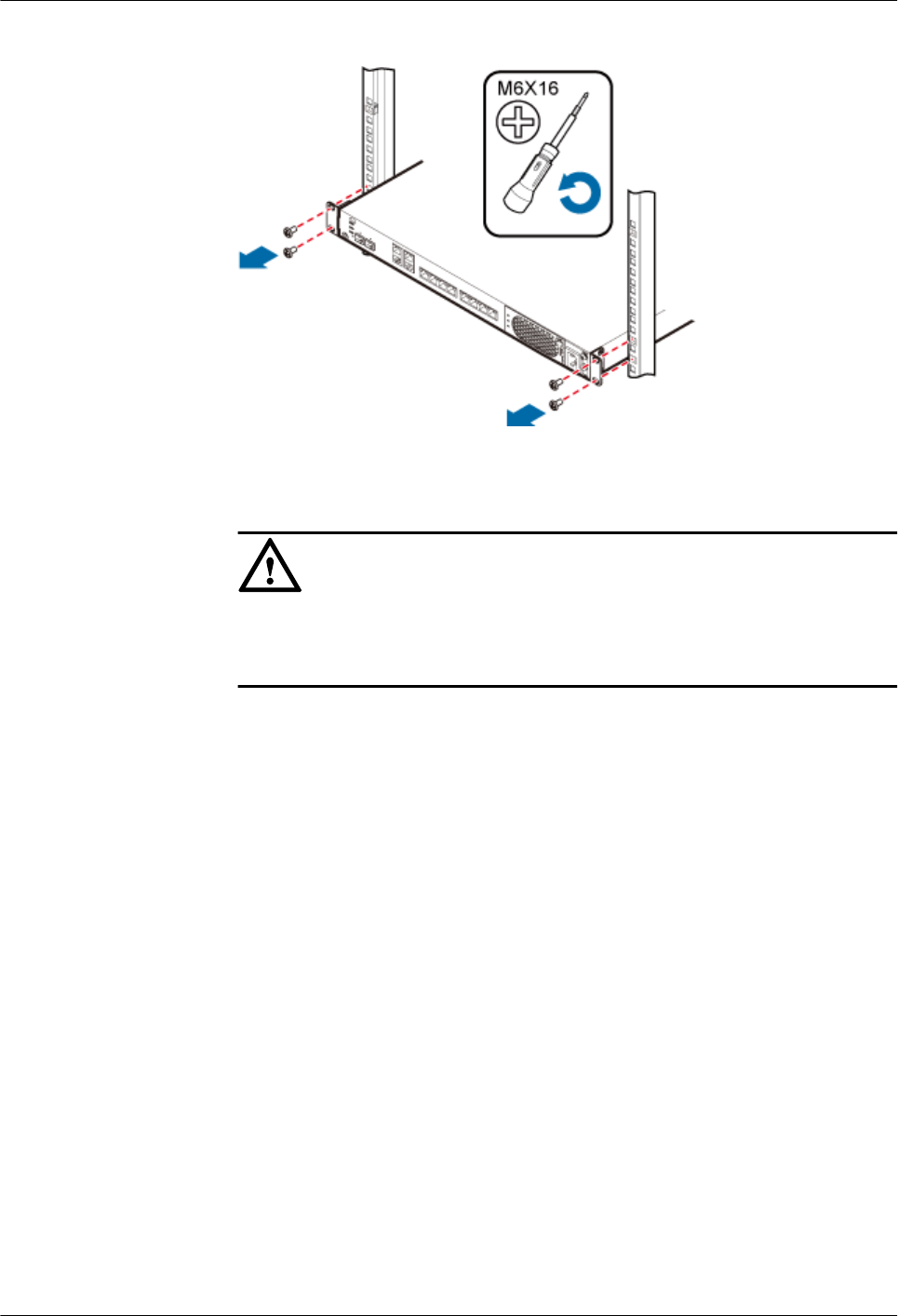
Figure 6-1 Removing the mounting ear
5. Remove the RHUB3908 from the rack.
6. Install the new RHUB3908. For details, see LampSite Installation Guide.
NOTICE
Take proper ESD protection measures, such as wearing an ESD wrist strap or ESD
gloves to prevent electrostatic damage to the boards, modules, or electronic
components.
7. Connect all the cables to the new RHUB3908 according to the recorded installations.
8. Power on the RHUB3908 by referring to 4.1 Powering On the RHUB3908.
9. Determine whether the new RHUB3908 is working properly according to the indicator
status on the RHUB3908. For details about the indicator status, see RHUB3908 Ports
and Indicators in LampSite Hardware Description.
lReplace the RHUB3908 installed on a wall.
1. Power off the RHUB3908 by referring to 4.2 Powering Off the RHUB3908.
2. Record the cable connections.
3. Take insulation measures, and then remove all cables from the RHUB3908.
4. Use a torque wrench or socket wrench to remove the four expansion bolts on the
mounting ear, and then remove the RHUB3908, as shown in Figure 6-2.
LampSite
Site Maintenance Guide 6 Replacing the RHUB3908
Issue 05 (2015-01-15) Huawei Proprietary and Confidential
Copyright © Huawei Technologies Co., Ltd.
18
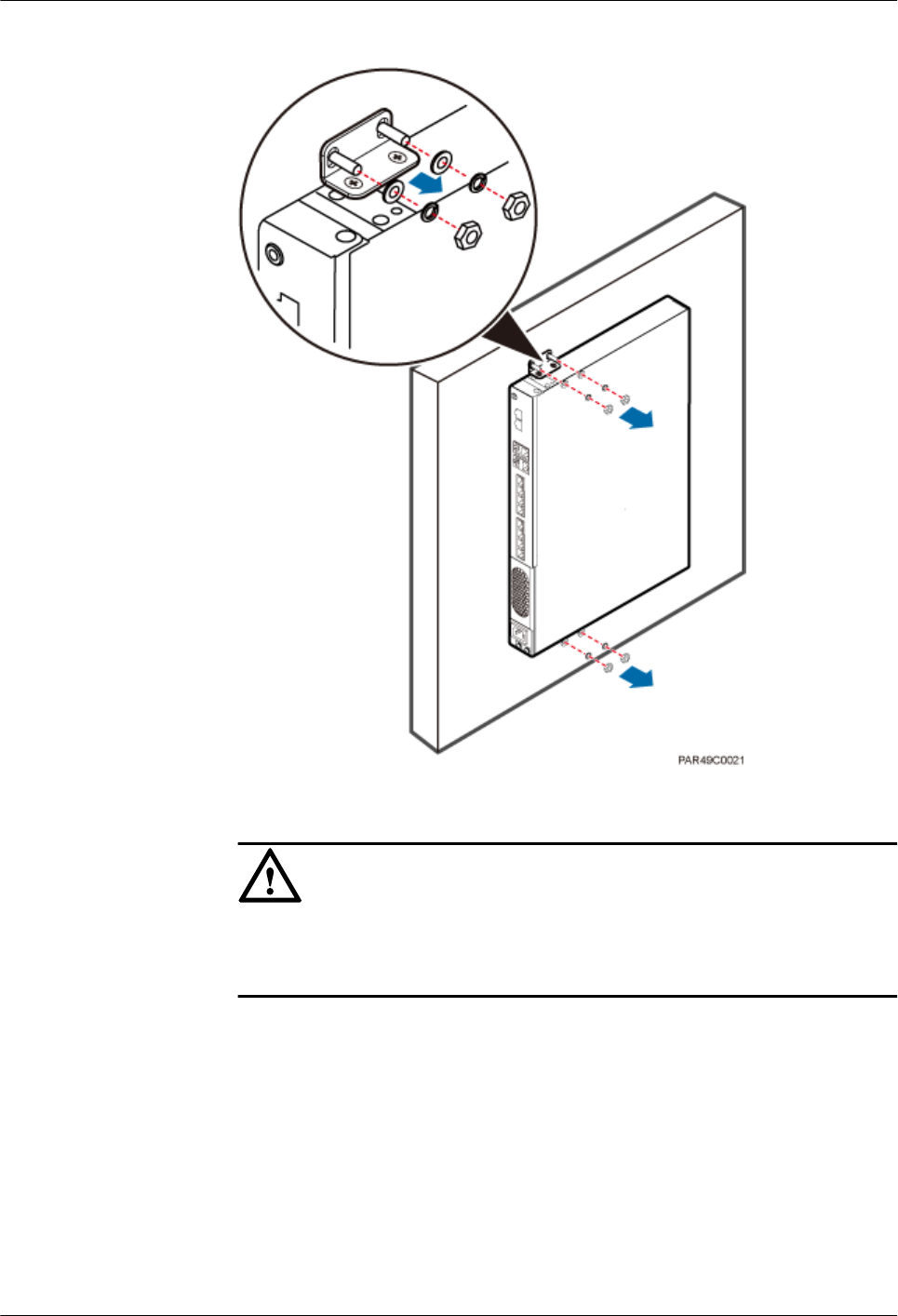
Figure 6-2 Removing the mounting ear
5. Install the new RHUB3908 on a wall. For details, see LampSite Installation Guide.
NOTICE
Take proper ESD protection measures, such as wearing an ESD wrist strap or ESD
gloves to prevent electrostatic damage to the boards, modules, or electronic
components.
6. Connect all the cables to the new RHUB3908 according to the recorded installations.
7. Power on the RHUB3908 by referring to 4.1 Powering On the RHUB3908.
8. Determine whether the new RHUB3908 is working properly according to the indicator
status on the RHUB3908. For details about the indicator status, see RHUB3908 Ports
and Indicators in LampSite Hardware Description.
----End
LampSite
Site Maintenance Guide 6 Replacing the RHUB3908
Issue 05 (2015-01-15) Huawei Proprietary and Confidential
Copyright © Huawei Technologies Co., Ltd.
19

Follow-up Procedure
lPlace the replaced RHUB3908 into an ESD box or bag. Then, place the ESD box or bag
into a foam-padded carton or the packing box of the new optical module.
lRecord the information about the faulty component in the fault card.
lContact the local Huawei office to deal with the faulty component.
LampSite
Site Maintenance Guide 6 Replacing the RHUB3908
Issue 05 (2015-01-15) Huawei Proprietary and Confidential
Copyright © Huawei Technologies Co., Ltd.
20
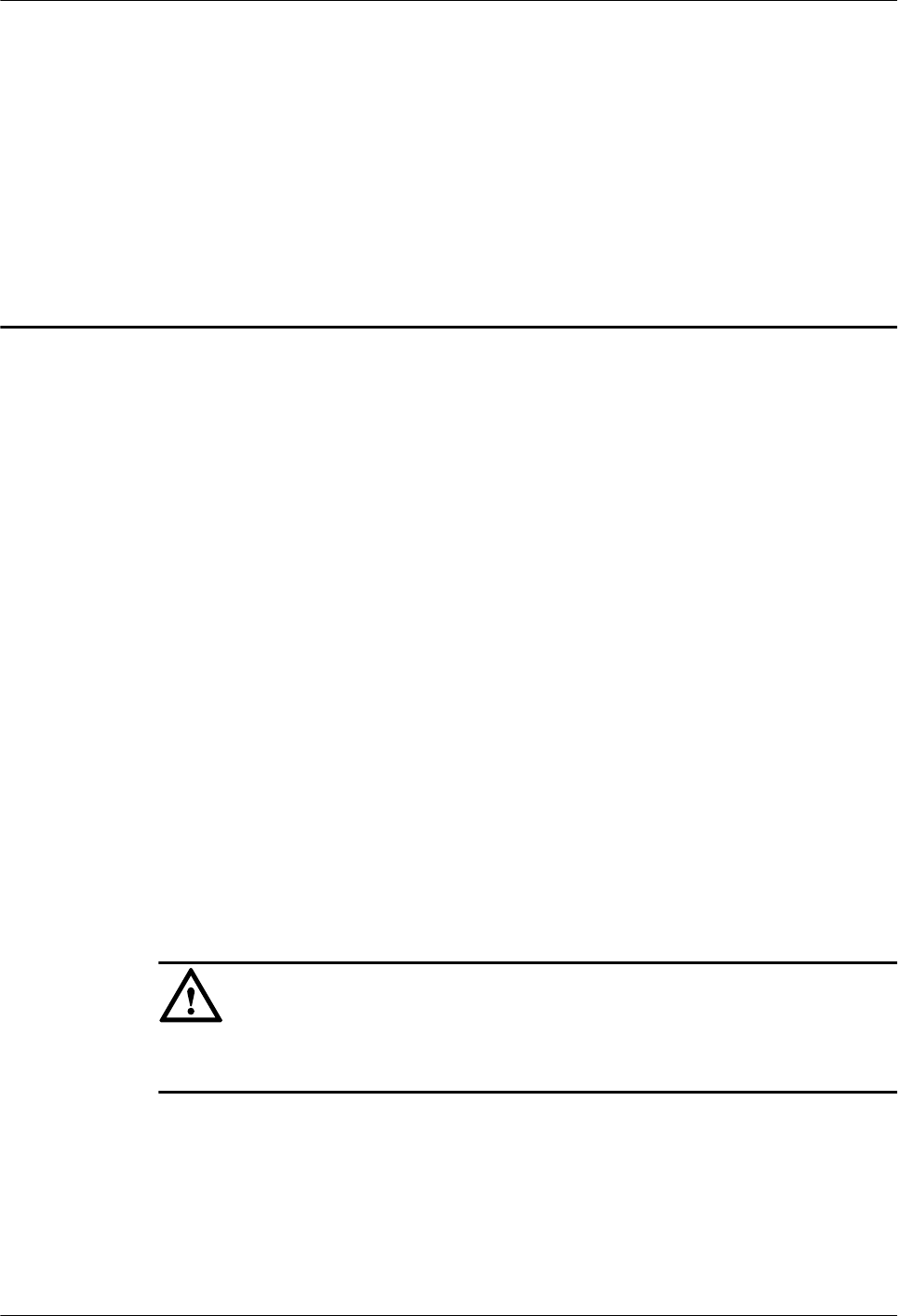
7 Replacing an Optical Module
An optical module provides a port for opto-electronic conversion. This enables the transmission
between the RHUB3908 and BBU3900 through the optical fiber. Replacing the optical module
requires removing the optical fibers. This interrupts all the services.
Prerequisites
lThe number and type of faulty optical modules are confirmed, and new optical modules
are available.The new optical modules to be installed must match CPRI rates.
lThe position for installing an optical module and the cable connection are recorded.
lThe following tools and materials are available: an ESD wrist strap or ESD gloves, and an
ESD box or bag.
Context
lThe optical modules are connected to the CPRI0 and CPRI1 ports on the RHUB3908 panel.
lAn optical module or CPRI fiber optic cable cannot be inserted into or removed from this
CPRI port when the power supply is connected.
lReplacing an optical module involves removing an optical fiber and the faulty optical
module, installing a new optical module, connecting the optical fiber to the optical module,
and recovering the links. The operation takes about 10 minutes.
NOTICE
Take proper ESD protection measures, such as wearing an ESD wrist strap or ESD gloves to
prevent electrostatic damage to the boards, modules, or electronic components.
Procedure
Step 1 Wear ESD gloves.
Step 2 Record the optical module and fiber connections.
Step 3 Power off the RHUB3908 according to the instructions in 4.2 Powering Off the RHUB3908.
LampSite
Site Maintenance Guide 7 Replacing an Optical Module
Issue 05 (2015-01-15) Huawei Proprietary and Confidential
Copyright © Huawei Technologies Co., Ltd.
21
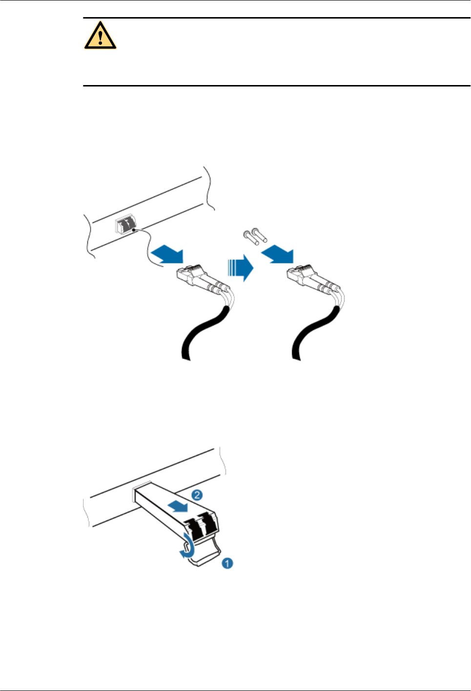
CAUTION
After removing the optical fiber from the optical module, do not look directly at the optical
modules without eye protection.
Step 4 Press the latch on the connector of the optical fiber connector, and remove the connector from
the faulty optical module, use the dust-proof cap to protect the optical fiber, as shown in Figure
7-1.
Figure 7-1 Removing the optical fiber
Step 5 Turn the ring-pull on the faulty optical module outwards. Hold the ring-pull and take the faulty
optical module out of the slot to remove it from the CPRI0 or CPRI1 port, as shown in Figure
7-2.
Figure 7-2 Removing the optical module
Step 6 Install the new optical module onto the corresponding CPRI port, as shown in Figure 7-3.
LampSite
Site Maintenance Guide 7 Replacing an Optical Module
Issue 05 (2015-01-15) Huawei Proprietary and Confidential
Copyright © Huawei Technologies Co., Ltd.
22
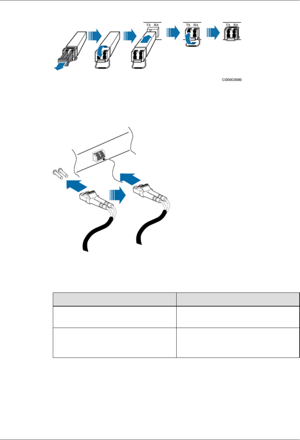
Figure 7-3 Installing the new optical module
Step 7 Remove the dust-proof caps from the optical module and optical fiber, and connect the optical
fiber connector to the new optical module, as shown in Figure 7-4.
Figure 7-4 Installing the optical fiber
Step 8 Power on the RRU according to the instructions in 4.1 Powering On the RHUB3908.
Step 9 Check whether CPRI signal transmission recovers by observing the CPRI indicator on the
RHUB3908 panel.
If... Then...
The CPRI indicator is green CPRI signal transmission recovers and the
optical fiber replacement is successful.
The CPRI indicator is red or in another color CPRI signal transmission is abnormal. Check
whether the optical fiber and optical module
are securely installed.
Step 10 Take off the ESD gloves and pack up all the tools.
----End
LampSite
Site Maintenance Guide 7 Replacing an Optical Module
Issue 05 (2015-01-15) Huawei Proprietary and Confidential
Copyright © Huawei Technologies Co., Ltd.
23

Follow-up Procedure
lPlace the replaced optical module into an ESD box or bag. Then, place the ESD box or bag
into a foam-padded carton or the packing box of the new optical module.
lRecord the information about the faulty component in the fault card.
lContact the local Huawei office to deal with the faulty component.
LampSite
Site Maintenance Guide 7 Replacing an Optical Module
Issue 05 (2015-01-15) Huawei Proprietary and Confidential
Copyright © Huawei Technologies Co., Ltd.
24

8 Replacing the pRRU3901
pRRU3901 is an indoor remote radio unit. It processes RF signals. Replacing the pRRU3901
interrupts all the services carried on it.
Prerequisites
lReplacing the pRRU3901 when:
–The functional modules inside a pRRU3901 or the housing of pRRU3901 is damaged.
–Adding the RF daughter board or Wi-Fi daughter board.
lThe hardware type is confirmed and a new pRRU3901 is available.
lThe labels and connections of the cables connected to the pRRU3901 are recorded.
lThe following tools are available: an electrostatic discharge (ESD) wrist strap and ESD
gloves.
Context
It takes about 5 minutes to replace the pRRU3901.
NOTE
The pRRU3901 can be installed on a metal pole, wall, or ceiling, and the procedures for replacing the
pRRU3901 are almost the same. The following uses a ceiling-mounted pRRU3901 as an example.
Procedure
Step 1 Instruct the network operator to block the pRRU3901.
NOTE
The LampSite solution supports immediate block, idle block, and delayed block. Application of idle block
and delayed block produces the same effect as application of immediate block.
lOn the UMTS side, log in to the LMT and run the BLK BRD command to block the RF
daughter board of the pRRU3901.
lOn the LTE side, log in to the LMT and run the BLK BRD command to block the RF daughter
board of the pRRU3901.
Step 2 Wear ESD gloves.
LampSite
Site Maintenance Guide 8 Replacing the pRRU3901
Issue 05 (2015-01-15) Huawei Proprietary and Confidential
Copyright © Huawei Technologies Co., Ltd.
25
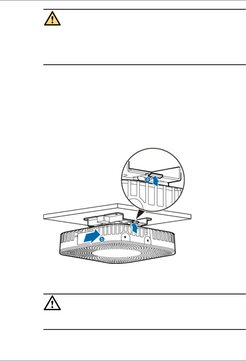
CAUTION
lTake proper ESD protection measures, such as wearing ESD gloves to prevent electrostatic
damage to the boards, modules, or electronic components.
lA pRRU3901 that has just been powered off has afterheat. Take scald-proof measures when
removing the pRRU3901.
Step 3 Power off the pRRU3901. For details, see 5.2 Powering Off the pRRU3901.
Step 4 Record the cable connections.
Step 5 Take insulation measures, and then remove all cables from the pRRU3901.
Step 6 Hold the pRRU3901 case in one hand and pull the hoist clamp on the mounting bracket with the
other hand, as shown in step a in Figure 8-1. Then, remove the mounting bracket from the
pRRU3901, as shown in step b in Figure 8-1.
Figure 8-1 Removing the pRRU3901
Step 7 Install the new pRRU3901. The installation must be based on different scenarios. For details,
see LampSite Installation Guide.
NOTICE
Take proper ESD protection measures, such as wearing an ESD wrist strap or ESD gloves to
prevent electrostatic damage to the boards, modules, or electronic components.
Step 8 Connect the cables to the pRRU3901 according to the recorded positions.
Step 9 Power on the pRRU3901 by referring to 5.1 Powering On the pRRU3901.
LampSite
Site Maintenance Guide 8 Replacing the pRRU3901
Issue 05 (2015-01-15) Huawei Proprietary and Confidential
Copyright © Huawei Technologies Co., Ltd.
26

Step 10 Check whether the new pRRU3901 is working properly according to the indicator status on the
pRRU3901. For details about the indicator status, see pRRU3901 Ports and Indicators in
LampSite Hardware Description.
Step 11 Instruct the network operator to unblock the pRRU3901.
1. On the UMTS side, log in to the NodeB LMT and run the UBL BRD command to unblock
the RF daughter board of the pRRU3901.
2. On the LTE side, log in to the eNodeB LMT and run the UBL BRD command to unblock
the RF daughter board of the pRRU3901.
Step 12 Take off the ESD gloves and pack up all the tools.
----End
LampSite
Site Maintenance Guide 8 Replacing the pRRU3901
Issue 05 (2015-01-15) Huawei Proprietary and Confidential
Copyright © Huawei Technologies Co., Ltd.
27

Regulatory Compliance Statement
pRRU3901, pRRU3901 AWS+PCS+WIFI
Issue: 02
Date:2014-12-11
HUAWEI TECHNOLOGIES CO., LTD.

Issue (02)
Huawei Proprietary and Confidential
Copyright © Huawei Technologies Co., Ltd.
i
Copyright © Huawei Technologies Co., Ltd. 2010. All rights reserved.
No part of this document may be reproduced or transmitted in any form or by any means without prior written
consent of Huawei Technologies Co., Ltd.
Trademarks and Permissions
and other Huawei trademarks are trademarks of Huawei Technologies Co., Ltd.
All other trademarks and trade names mentioned in this document are the property of their respective holders.
Notice
The purchased products, services and features are stipulated by the contract made between Huawei and the customer.
All or part of the products, services and features described in this document may not be within the purchase scope or
the usage scope. Unless otherwise specified in the contract, all statements, information, and recommendations in this
document are provided "AS IS" without warranties, guarantees or representations of any kind, either express or
implied.
The information in this document is subject to change without notice. Every effort has been made in the preparation
of this document to ensure accuracy of the contents, but all statements, information, and recommendations in this
document do not constitute the warranty of any kind, express or implied.
Huawei Technologies Co., Ltd.
Address:
Huawei Industrial Base
Bantian, Longgang
Shenzhen 518129
People's Republic of China
Website:
http://www.huawei.com
Email:
support@huawei.com

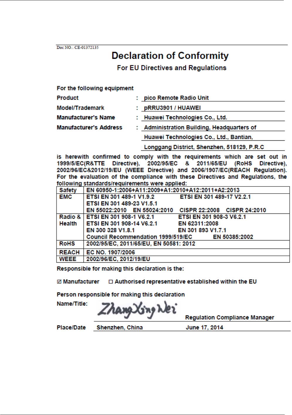

2 Regulatory Compliance Information
Issue (02)
Huawei Proprietary and Confidential
Copyright © Huawei Technologies Co., Ltd.
2-1
2 Regulatory Compliance Information
About This Chapter
2.1 Regulatory Compliance Standards
2.2 European Regulatory Compliance
2.3 U.S.A Regulatory Compliance
2.4 Canada Regulatory Compliance
2.5 Japanese Regulatory Compliance
2.6 CISPR 22 Compliance
2.7 China RoHS hazardous substance table
2.8 India RoHS hazardous substance table
2.9 Other Markets
2.1 Regulatory Compliance Standards
The Product complies with the standards listed in Table 2-1.

2 Regulatory Compliance Information
2-2
Huawei Proprietary and Confidential
Copyright © Huawei Technologies Co., Ltd.
Issue (02)
Table 2-1 Regulatory compliance standards
Discipline
Standards
EMC
CISPR22 Class B
CISPR24
EN55022 Class B
EN50024
ETSI EN 301 489 Class B
CFR 47 FCC Part 15 Class B
ICES 003 Class B
AS/NZS CISPR22 Class B
GB9254 Class B
VCCI Class B
CNS 13438 Class B
IEC/EN61000-3-2
IEC/EN61000-3-3
IEC/EN61000-6-1
IEC/EN61000-6-3
RF
ETSI EN 301 908-1
ETSI EN 301 908-3
ETSI EN 301 908-14
ETSI EN 300 328
ETSI EN 301 893
Heath
ICNIRP Guideline
1999-519-EC
EN 50385
OET Bulletin 65
IEEE Std C95.1
EN 60215
EN 62311
Safety
IEC/EN 60950-1
IEC/EN41003
EN 60950-1
UL 60950-1
CSA C22.2 No 60950-1
AS/NZS 60950.1
BS EN 60950-1
IS 13252
GB4943

2 Regulatory Compliance Information
Issue (02)
Huawei Proprietary and Confidential
Copyright © Huawei Technologies Co., Ltd.
2-3
Discipline
Standards
Environmental protection
2011/65/EU (RoHS)
EC NO. 1907/2006 (REACH)
2002/96/EC (WEEE)
Grounding
ITU-T K.27
ETSI EN 300 253
NOTE
EMC: electromagnetic compatibility
NEBS: Network Equipment Build Standard
RF: radio frequency
CISPR: International Special Committee on Radio Interference
EN: European Standard
ETSI: European Telecommunications Standards Institute
CFR: Code of Federal Regulations
FCC: Federal Communication Commission
IEC: International Electrotechnical Commission
AS/NZS: Australian/New Zealand Standard
VCCI: Voluntary Control Council for Interference
CNS: Chinese National Standard
UL: Underwriters Laboratories
CSA: Canadian Standards Association
BS: British Standard
IS: Indian Standard
GR: General Requirement
FDA: Food and Drug Administration
BTS: Base Transceiver Station
GSM: Global System for Mobile communications
WLAN: wireless local area network
ICNIRP: International Commission on Non-Ionizing Radiation Protection
OET: Office of Engineering Technology
IEEE: Institute of Electrical and Electronics Engineers
RoHS: restriction of the use of certain hazardous substances
2.2 European Regulatory Compliance
The Product complies with the following European directives and regulations.
2004/108/EC (EMC)
2006/95/EC (low voltage)
1999/5/EC (R&TTE)
2011/65/EU (RoHS)
EC NO. 1907/2006 (REACH)
2 Regulatory Compliance Information
2-4
Huawei Proprietary and Confidential
Copyright © Huawei Technologies Co., Ltd.
Issue (02)
2002/96/EC (WEEE)
Product complies with Directive 2002/95/EC, 2011/65/EU and other similar regulations from
the countries outside the European Union, on the RoHS in electrical and electronic equipment.
The device does not contain lead, mercury, cadmium, and hexavalent chromium and
brominated flame retardants (Polybrominated Biphenyls (PBB) or Polybrominated Diphenyl
Ethers (PBDE)) except for those exempted applications allowed by RoHS directive for
technical reasons.
Product complies with Regulation EC NO. 1907/2006 (REACH) and other similar regulations
from the countries outside the European Union. Huawei will notify to the European Chemical
Agency (ECHA) or the customer when necessary and regulation requires.
Product complies with Directive 2002/96/EC on waste electrical and electronic equipment
(WEEE). Huawei is responsible for recycling its end-of-life devices, and please contact
Huawei local service center when recycling is required. Huawei strictly complies with the EU
Waste Electrical and Electronic Equipment Directive (WEEE Directive) and electronic waste
management regulations enacted by different countries worldwide. In addition, Huawei has
established a system for recycling and reuse of electronic wastes, and it can provide service of
dismantling and recycling for WEEE. By Huawei recycling system, the waste can be handled
environmentally and the resource can be recycled and reused fully, which is also Huawei
WEEE stratagem in the word. Most of the materials in product are recyclable, and our
packaging is designed to be recycled and should be handled in accordance with your local
recycling policies.
In accordance with Article 11(2) in Directive 2002/96/EC (WEEE), products were marked
with the following symbol: a cross-out wheeled waste bin with a bar beneath as below:
2.3 U.S.A Regulatory Compliance
2.3.1FCC Part 15
The Product complies with Part 15 of the FCC Rules. Operation is subject to the following
two conditions:
This device does not cause harmful interference.
This device must accept any interference received, including interference that may cause
undesired operation.

2 Regulatory Compliance Information
Issue (02)
Huawei Proprietary and Confidential
Copyright © Huawei Technologies Co., Ltd.
2-5
If this device is modified without authorization from Huawei, the device may no longer
comply with FCC requirements for Class B digital devices. In that a case, your right to use the
device may be limited by FCC regulations. Moreover, you may be required to correct any
interference to radio or television communications at your own expense.
This device has been tested and found to comply with the limits for a Class B digital device,
pursuant to Part 15 of the FCC rules. These limits are designed to provide reasonable
protection against harmful interference in a residential installation.
This device generates, uses and radiates radio frequency energy. If it is not installed and used
in accordance with the instructions, it may cause harmful interference to radio
communications.
However, there is no guarantee that interference will not occur in a particular installation. If
this device does cause harmful interference to radio or television reception, which can be
determined by turning the device off and on, the user may take one or more of the following
measures:
Reorient or relocate the receiving antenna.
Reinforce the separation between the device and receiver.
Connect the device into an outlet on a circuit different from that to which the receiver is
connected.
Consult the dealer or an experienced radio or TV technician for assistance.
This product may contains FCC ID QISPRU01B02 or FCC ID QISPRU01B01 or
QISPRU02WLAN or their combination both or three transmitters
2.4 Canada Regulatory Compliance
2.4.1 RSS-Gen statement
This device complies with Industry Canada licence-exempt RSS standard(s).
Operation is subject to the following two conditions: (1) this device may not cause
interference, and (2) this device must accept any interference, including interference that may
cause undesired operation of the device.
Le présent appareil est conforme aux CNR d'Industrie Canada applicables aux appareils radio
exempts de licence. L'exploitation est autorisée aux deux conditions suivantes : (1) l'appareil
ne doit pas produire de brouillage, et (2) l'utilisateur de l'appareil doit accepter tout brouillage
radioélectrique subi, même si le brouillage est susceptible d'en compromettre le
fonctionnement.
2.4.2 RSS-102 statement
This device is designed and manufactured not to exceed the emission limits for exposure to
radio frequency (RF) energy set by Industrial Canada and meets the requirements for radiation
exposure limits set forth for an uncontrolled environment.
In order to avoid the possibility of exceeding the Industrial Canada radio frequency exposure
limits, human proximity to the equipment shall not be less than 0.2m
2 Regulatory Compliance Information
2-6
Huawei Proprietary and Confidential
Copyright © Huawei Technologies Co., Ltd.
Issue (02)
Cet appareil est conçu et fabriqué pour ne pas dépasser les limites d'émission pour l'exposition
à la fréquence radio (RF) de l'énergie fixé par l'Industrielle Canada et répond aux exigences en
matière de limites d'exposition aux rayonnements définies pour un environnement non
contrôlé.
Afin d'éviter la possibilité de dépasser les limites d'exposition aux fréquences radio
industrielle du Canada, la proximité humaine pour l'appareil nedoit pas être inférieure à0.2m
This product may contains IC 6369A-PRU01B02 or IC 6369A-PRU01B01 or
6369A-PRU02WLAN or their combination both or three transmitters
2.5 Japanese Regulatory Compliance
2.4.1VCCI
The Product complies with VCCI Class B by Information Technology Equipment (ITE).
The preceding translates as follows:
This is a Class B product based on the standard of the Voluntary Control Council for
Interference by Information Technology Equipment (VCCI).If this product is used
Near a radio or television receiver in a domestic environment. It may cause radio
Interference.Install and use the equipment according to the instruction manual.
2.6 CISPR 22 Compliance
The Product complies with CISPR 22 for Class B by the ITE.
2.7 China RoHS hazardous substance table
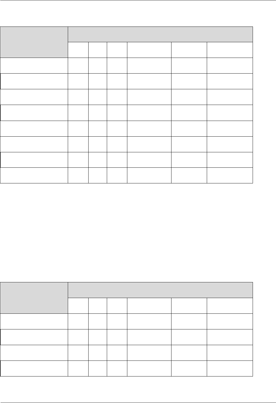
2 Regulatory Compliance Information
Issue (02)
Huawei Proprietary and Confidential
Copyright © Huawei Technologies Co., Ltd.
2-7
This products described in this guide complies with “the Administration on the Control of Pollution Caused by
Electronic Information Products” which is also called China RoHS
部件名称
产品中有害物质或元素的名称及含量
镉
铅
汞
六价铬
多溴联苯
多溴联苯醚
Alloy Parts
〇
╳
〇
〇
〇
〇
Metal Fittings
〇
〇
〇
〇
〇
〇
PCBA
〇
╳
〇
〇
〇
〇
Capacitor
〇
╳
〇
〇
〇
〇
Other electronics
〇
╳
〇
〇
〇
〇
Solder
〇
╳
〇
〇
〇
〇
Cable
〇
〇
〇
〇
〇
〇
Plastic and Polymer
〇
〇
〇
〇
〇
╳
〇:表示该有毒有害物质在该部件所有均质材料中的含量均在SJ/T11363-2006 标准规定的限量要求以下。
╳:表示该有毒有害物质至少在该部件的某一均质材料中的含量超出SJ/T11363-2006 标准规定的限量要
求。
2.8 India RoHS hazardous substance table
This products described in this guide complies with the “e-waste (Management and Handling) Rules, 2011”of
India which is also called India RoHS.
Part Descriptions
Restricted Substances in Product
Cd
Pb
Hg
Cr(VI)
PBBs
PBDEs
Alloy Parts
〇
╳
〇
〇
〇
〇
Metal Fittings
〇
〇
〇
〇
〇
〇
PCBA
〇
╳
〇
〇
〇
〇
Capacitor
〇
╳
〇
〇
〇
〇

2 Regulatory Compliance Information
2-8
Huawei Proprietary and Confidential
Copyright © Huawei Technologies Co., Ltd.
Issue (02)
Other electronics
〇
╳
〇
〇
〇
〇
Solder
〇
╳
〇
〇
〇
〇
Cable
〇
〇
〇
〇
〇
〇
Plastic and Polymer
〇
〇
〇
〇
〇
╳
〇: indicates that the content of the toxic and hazardous substance in all the Homogeneous Materials of the part is
below the concentration limit requirement as described in the e-waste (Management and Handling) Rules, 2011.
╳: indicates that the content of the toxic and hazardous substance in at least one Homogeneous Material of the
part exceeds the concentration limit requirement as described in S in the e-waste (Management and Handling)
Rules, 2011.
2.9 Other Markets
For relevant compliance information/documentation for markets not mentioned above,
Please contact Huawei representative