Huawei Technologies RRU3201-700M Distributed Base Station Remote Radio Unit User Manual Installation Guide 2
Huawei Technologies Co.,Ltd Distributed Base Station Remote Radio Unit Installation Guide 2
Contents
- 1. Installation Guide 1
- 2. Installation Guide 2
Installation Guide 2
15
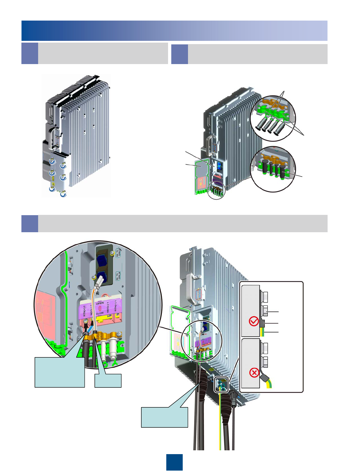
Installing the RRU Cables
bOpen the cover plate of the
RRU cabling cavity
Cover plate of the
cabling cavity
Cabling cavity
Cable trough for the optical cable
CCabling Cavity of the RRU
Cable trough for the
power cable
Waterproof filler
dCable Connections of the RRU
Shielding
layer of the
power cable Strap
Waterproof
tape
Grounding
screw
OT terminal
PGND cable
16
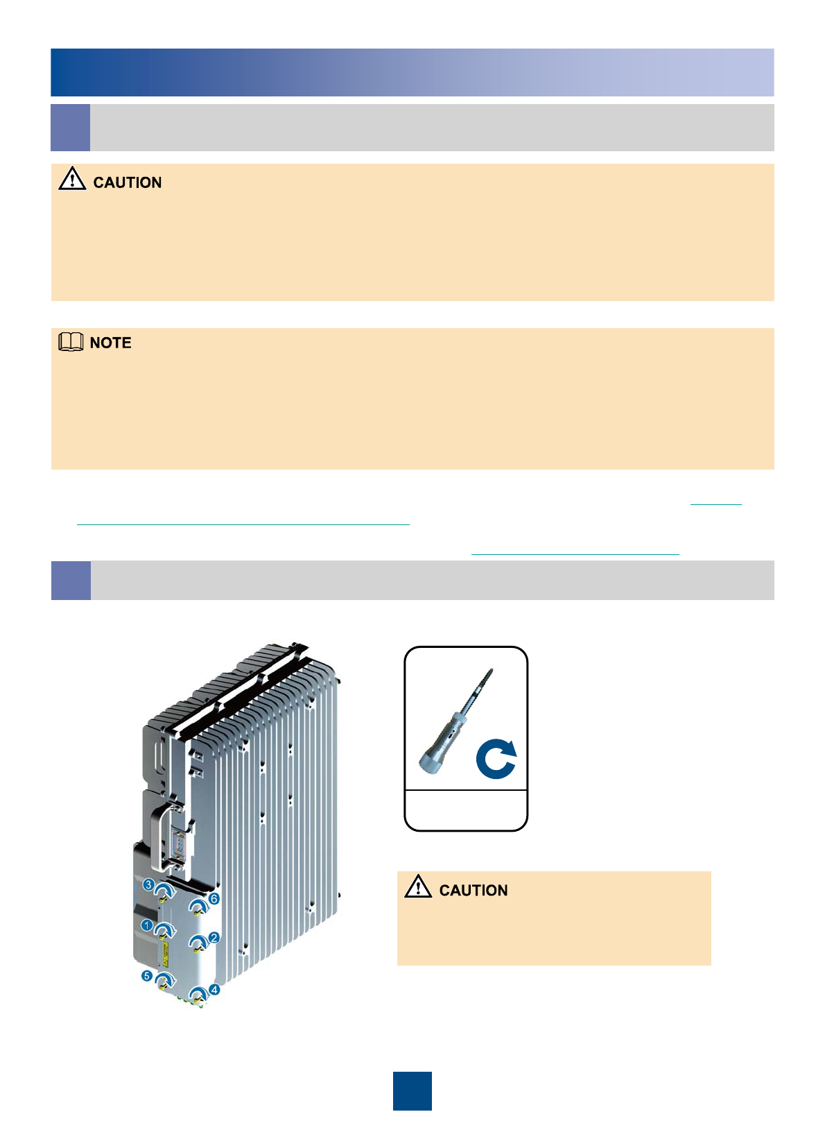
Installing the RRU Cables
dCable Connections of the RRU
For details on how to add the OT terminals to the power cable, see pages 22 to 23 Adding
OT Terminals to the Power Cable of the RRU.
For details installing the Optical Module, see page 24 Installing the Optical Module.
eClose the cover plate of the RRU cabling cavity
1.4N•m
zWhen wrapping the waterproofing tape, apply even force to extend the tape until the width of the tape is 1/2 of the
original width.
zWrap the joint spirally upward, downward, and then upward again. In other words, the joint is wrapped by three layers of
the tape. Ensure that the upper layer of the tape covers about half of the lower layer when wrapping up the tape.
zDo not remove the dustproof cap from the idle antenna port. Perform the waterproof, dustproof, and smokeproof
treatment if necessary. Use the waterproof tape to wrap the joints in outdoor applications.
zUse the power cable clip to press the shielding layer tightly and ensure that the lower part of the shielding layer does not
exceed the position shown in the preceding figure.
zThe grounding resistance of the PGND cable should be less than 10 ohms. The PGND cable cannot be connected to the
grounding terminal.
zGround the shielding layer of the other end of the power cable.
zAfter the cables are installed on the RRU, insert the waterproofing fillers into the idle cable holes.
1. The screw on the cover plate is tightened until the
fastening torque is 1.4 N• m.
2. The screws on the cover plate are tightened in the
order shown in the preceding figure.
17
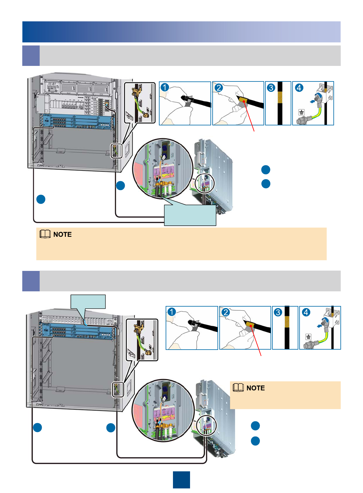
Installing the RRU Cables
fRRU+APM30H
RRU power cable
CPRI optical cable
1. The RRU power cable is connected to one group of the RRU0 to RRU5 terminals of the PDU.
2. Strip the jacket off the RRU power cable for a small part, press the exposed shielding layer on the strap, and
then connect the PGND cable on the strap to the nearest grounding bolt on the side in the APM30/APM30H.
RRU power
cable
25mm
Metal shielding layer
(25mm)
a
b
a
b
gRRU+TMC/TMC11H
The RRU power cable is connected to
LOAD0 to LOAD5 on the DCDU-03C.
LOAD0
RRU power cable
CPRI optical cable
25mm
Metal shielding layer
(25mm)
Grounding the shielding layer of the power cable:
Grounding the shielding layer of the power cable:
a
b
a
b
18
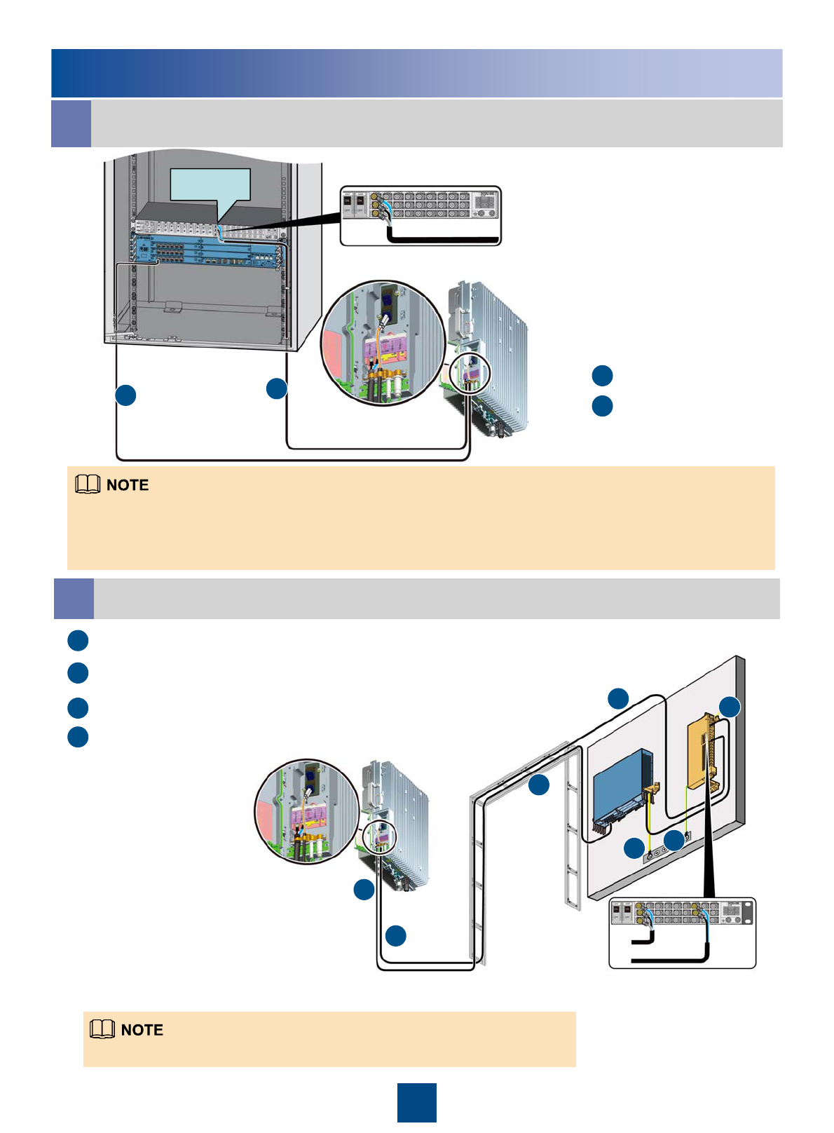
Installing the RRU Cables
zThe RRU power cable is connected to LOAD0 to LOAD5 on the DCDU-03C.
RRU power cable
CPRI optical cable
BBU power cable
c
d
a
b
hRRU+19-Inch cabinet
LOAD0
zAt the end of the RRU power cable connected to the DCDU-03C, you need to make the shielding layer of the power
cable into an OT terminal, and then connect the OT terminal to the PGND terminal of the corresponding port on the
DCDU-03C. For details about making an OT terminal, see pages 26 and 27.
zThe RRU power cable is connected to LOAD0 to LOAD5 on the DCDU-03C.
RRU power cable
CPRI optical cable
a
b
a
b
iRRU+BBU Installed Against the Wall
RRU
BBU
PGND cable
a
b
c
dd
a
b
19
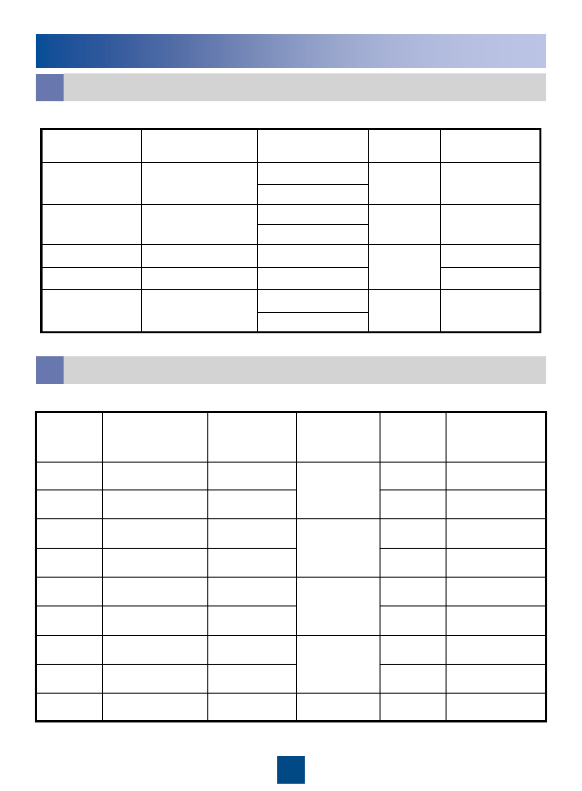
RRU Hardware Installation Checklist
No joint lies in the middle of the power cable or the PGND cable.5
The connectors of signal cables are intact and securely linked. And the signal cables are not damaged or
broken.
10
All labels, tags, and nameplates are correct, legible, and complete. All the labels at both ends of the cables,
jumpers and feeders should match.
11
The operating grounding and protection grounding of the base station and the lightning protection grounding
of the building share one group of grounding conductors.
9
The power cable, PGND cable and other cables need to be bound separately.8
The power cable and PGND cable are not short-circuited or reversely connected and are not damaged or
broken.
7
The lugs at both ends of the power cable or the PGND cable are securely soldered or crimped.6
Waterproof check: The empty cable troughs in the cabling cavity of the RRU are waterproofed. The cover
plate is tightly buckled on the cabling cavity of the RRU. The RF ports that are not connected with RF
cables are capped and waterproofed. The waterproof caps are fastened.
4
The cover plate is fastened to the RRU cabling cavity.3
The RRU is properly installed.2
The position for each equipment conforms to the engineering design and meets the space requirement.
Sufficient space is reserved for equipment maintenance.
1
ItemsNo.
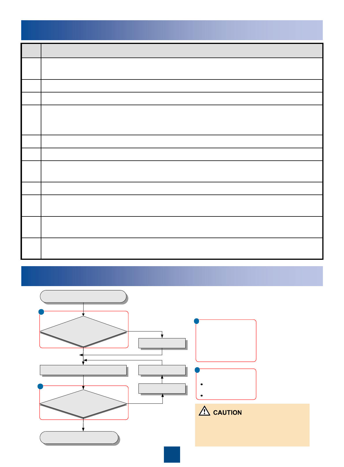
The RRU should be powered on in 24 hours
after being unpacked. The power off duration
of the RRU cannot exceed 24 hours during
maintenance.
Powering On the RRU
Check whether the
input voltage of the RRU is
normal?
Power on the RRU
Start
End
a
Yes
Power off the RRU
Rectify the fault
b
Check whether the
status of the LEDs on the
RRU is normal?
No
Yes
No
Rectify the fault
aNormal input voltage of the
RRU:
If the BBU is supplied with
-48 V DC power, the
external input power
voltage ranges from -57 V
DC to -36 V DC.
Normal status of the
LEDs on the RRU:
RUN LED: ON for 1s
and OFF for 1s
ALM LED: OFF
b
20
Reference
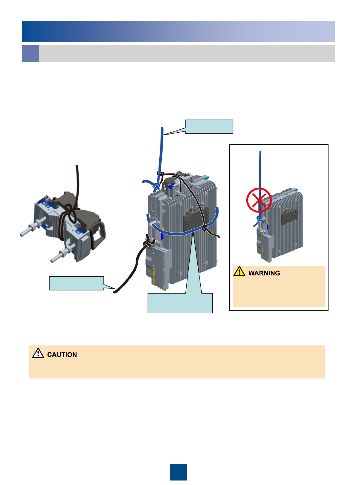
Lift the RRU and installation components to the tower.
a
Steering rope
Lifting rope
zWhen lifting the RRU to the tower, avoid collision of the RRU with the tower.
zLift the RRU to the tower before it is installed on the metal pole, angle steel, or U-steel.
Lower part of the
adapting piece
Do not fix only the handle
of the RRU to the lifting
rope.
1. Lead the lifting rope along the lower part of the adapting piece and then bind the
RRU by using the lifting rope at the handle of the RRU. Bind the main fixture and
auxiliary fixture by using the lifting rope. Bind the handle of the RRU by using the
pulling rope. See the following figure.
21
Reference
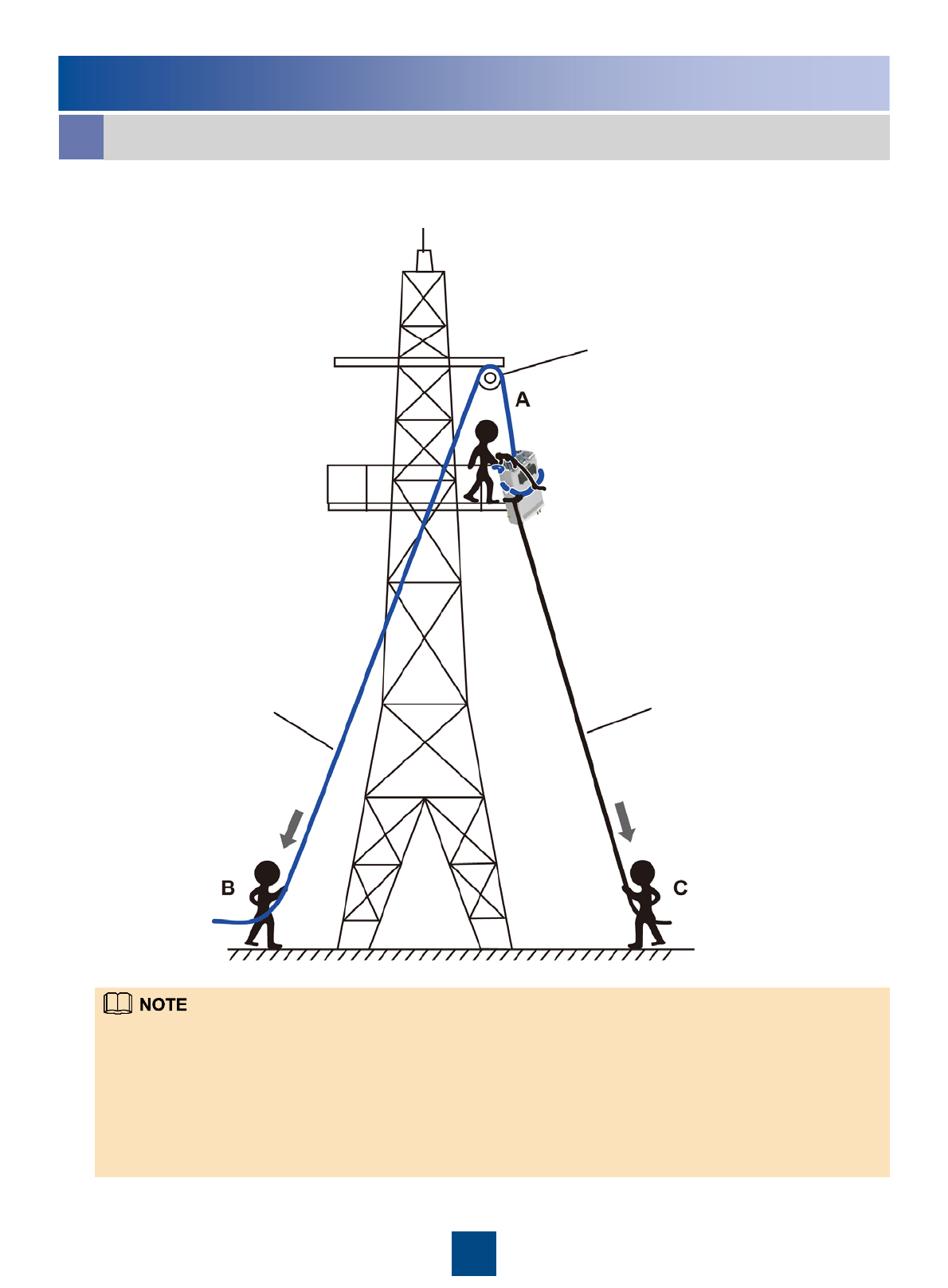
Lift the RRU and installation components to the tower.
a
2. Lift the RRU and installation components to the tower.
zInstaller A climbs up to the tower, installs the fixed pulley on the support of the tower platform, and then leads the lifting
rope through the fixed pulley.
zInstaller C binds the RRU and installation parts using the lifting rope and fixes the handle of the RRU to the pulling rope.
zInstaller B pulls the lifting rope downwards. At the same time, installer C pulls the steering rope outwards to avoid
collision of the RRU with the installation parts or tower.
zInstallers A catches the RRU and installation parts and then loosen the rope.
zOn a tower, multiple RRUs cannot be installed in centralized mode.
Fixed pulley
Steering rope
Lifting rope
22
Reference
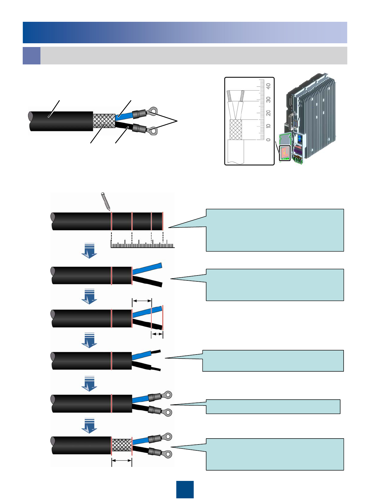
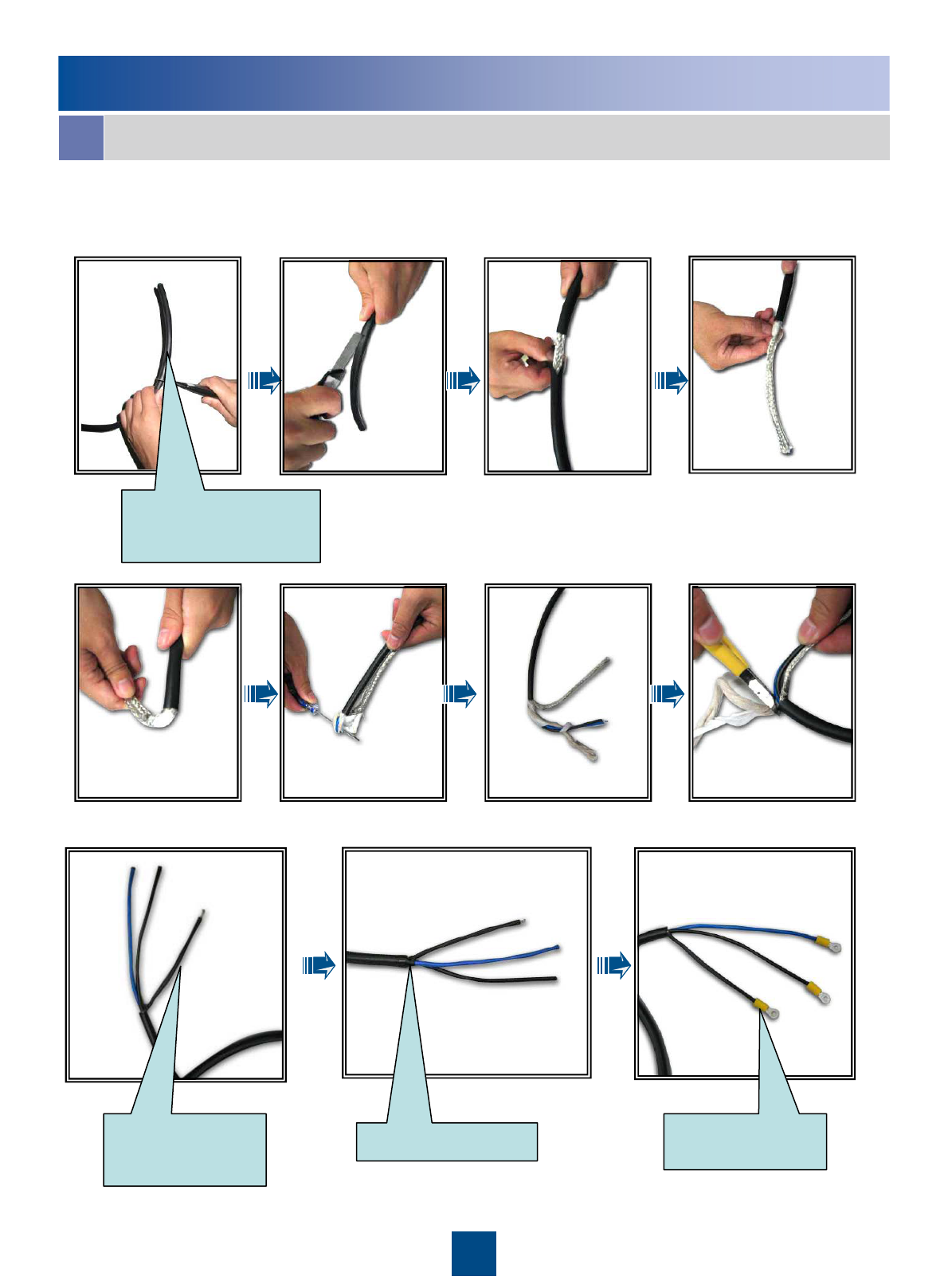
1. OT terminals on the power cable:
To assemble the OT terminals, perform the following steps:
Adding OT Terminals to the Power Cable of the RRU
b
Determine lengths of power cables for
different operations according to the
scales on the inner side of the cover
plate of the cabling cavity.
Based on the determined length,
remove the jacket and shielding layer
off the power cable.
Remove the jacket of a specified length
from each wire.
Add an OT terminal to each wire.
Remove about 15 mm jacket off the
power cable to expose the shielding
layer.
-48 V DC power cable
Shielding
layer GND wire
-48 V power wire
OT terminal
15mm
8mm
14mm
0 10203040
23
Reference
Adding OT Terminals to the Power Cable of the RRU
b
2.Assemble an OT terminal on the power cable at the end connecting to the
power supply device.
Stripped shielding
layer in the heat-
shrinkable tube
PVC insulating tape OT terminal on the
shielding layer
Determine the length on
site. The recommended
length is 150 mm.
24
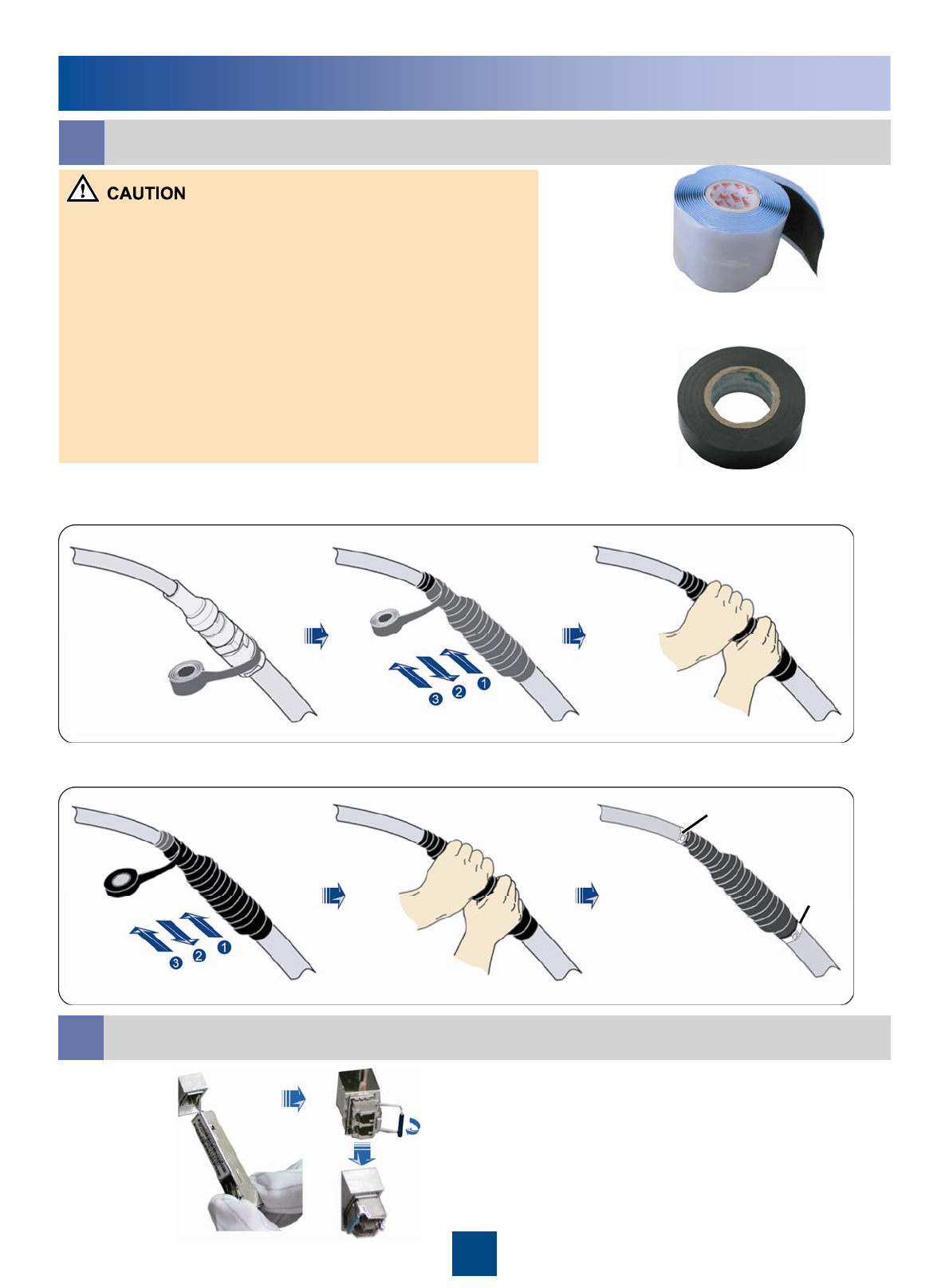
1. The waterproof tape should be wrapped for an extra length of 20
mm away from the connectors at both ends.
2. The tapes are wrapped around the connector from the lower part to
the upper part. When wrapped for another layer, the tapes may not be
cut off.
3. Apply average force to pull the tape until the width of the tape is 1/2
of the original width before wrapping up the waterproofing tape.
4. Ensure that the upper layer of the tape covers over 50% of the lower
layer when wrapping up the tape.
5. The Insulation tape should be wrapped for an extra length of 20 mm
away from the edge of the waterproof tape at both ends.
6. Make sure that the last layer of the waterproof tape is wrapped from
lower part to the upper part so that the rain flows along the wrapped
waterproof tape.
Waterproof tape
Insulation tape
1. Wrap up the connectors with three layers of waterproofing tape
2. Wrap up the connectors with three layers of Insulation tape
Tightly pressed
the tape
Tightly pressed
the tape
Use cable ties to fasten
both ends of the tapes.
Cable tie
Cable
tie
Waterproofing the outdoor cables
c
Reference
Installing the optical Module
d
25
Reference
Pin Assignment of the RRU AISG Extension cable
f
Brown
+24VTwisted pairWhite/brownX2.6X1.6
RS485 AGreenX2.5X1.5
RS485 BTwisted pairWhite/greenX2.3X1.3
Orange
DC Return ATwisted pairWhite/orangeX2.7X1.7
Blue
+12VTwisted pairWhite/blueX2.1X1.1
InstructionWire TypeWire ColorPin of the AISG female
connector
Pin of the AISG
male connector
Pin Assignment for the Wires of the RRU Alarm Cable
g
APM TX+X9
Twisted pair
BrownRS485_RX+X1.3
-
X8
X7
X6
X5
X4
X3
X2
Cord End
Terminal
---X1.shell
APM TX-
Shield
White/brownRS485_RX-X1.5
APM RX+GreenRS485_TX+X1.8
APM RX-Twisted pairWhite/greenRS485_TX-X1.6
GNDOrangeGNDX1.4
SWITCH_INPUT1+Twisted pairWhite/orangeSWITCH_INPUT1+X1.7
GNDBlueGNDX1.4
SWITCH_INPUT0+Twisted pairWhite/blueSWITCH_INPUT0+X1.2
LabelWire TypeWire ColorPin NameDB9
waterproof
Connector

26
Change History
01 (2009-06-05)
This is the draft release.
This describes the changes in the RRU3201 V100R001C01 Installation Guide

HUAWEI TECHNOLOGIES CO., LTD.
Huawei Industrial Base Bantian Longgang
Shenzhen 518129
People’s Republic of China
www.huawei.com