Huawei Technologies RRU3201-700M Distributed Base Station Remote Radio Unit User Manual Installation Guide 1
Huawei Technologies Co.,Ltd Distributed Base Station Remote Radio Unit Installation Guide 1
Contents
- 1. Installation Guide 1
- 2. Installation Guide 2
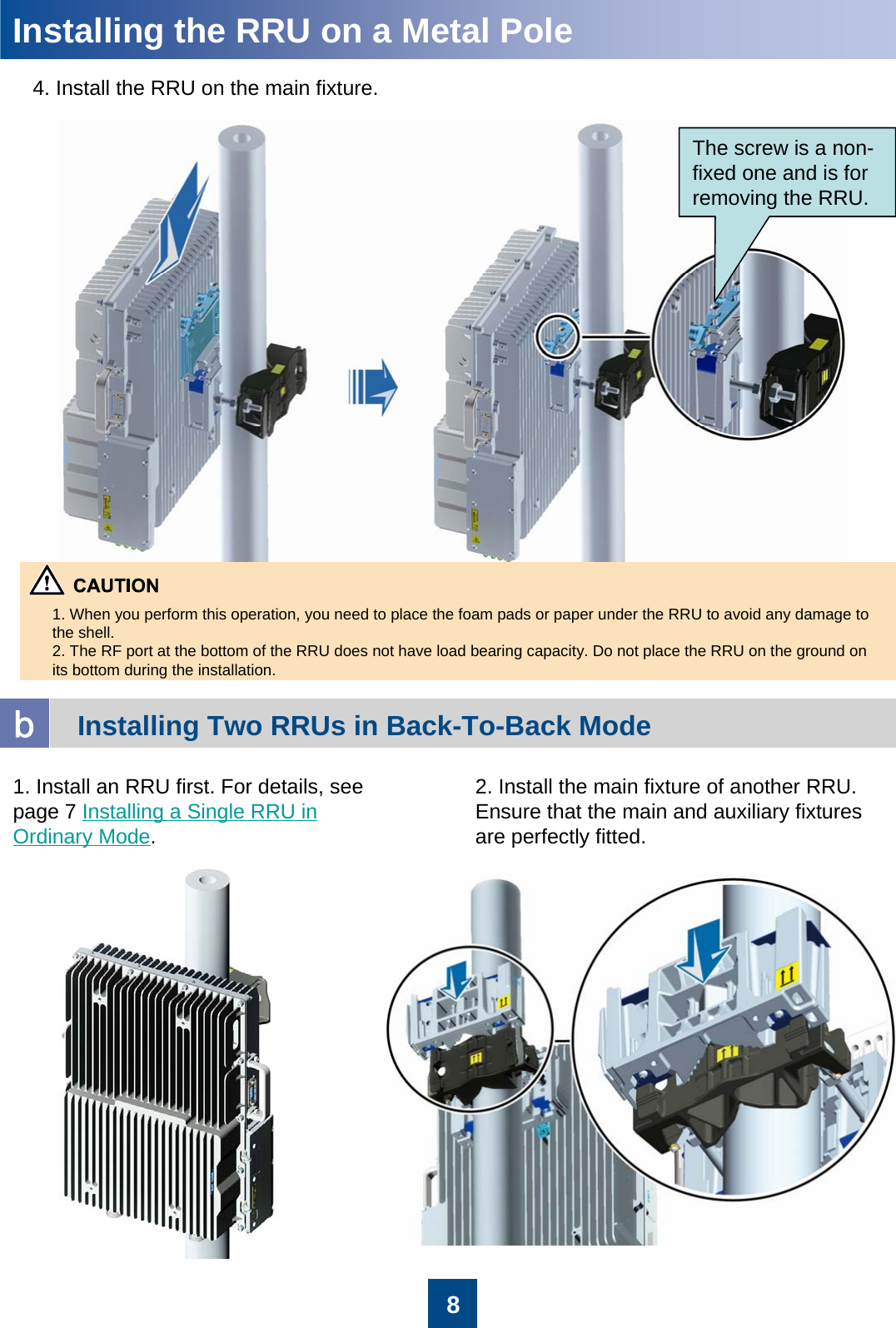
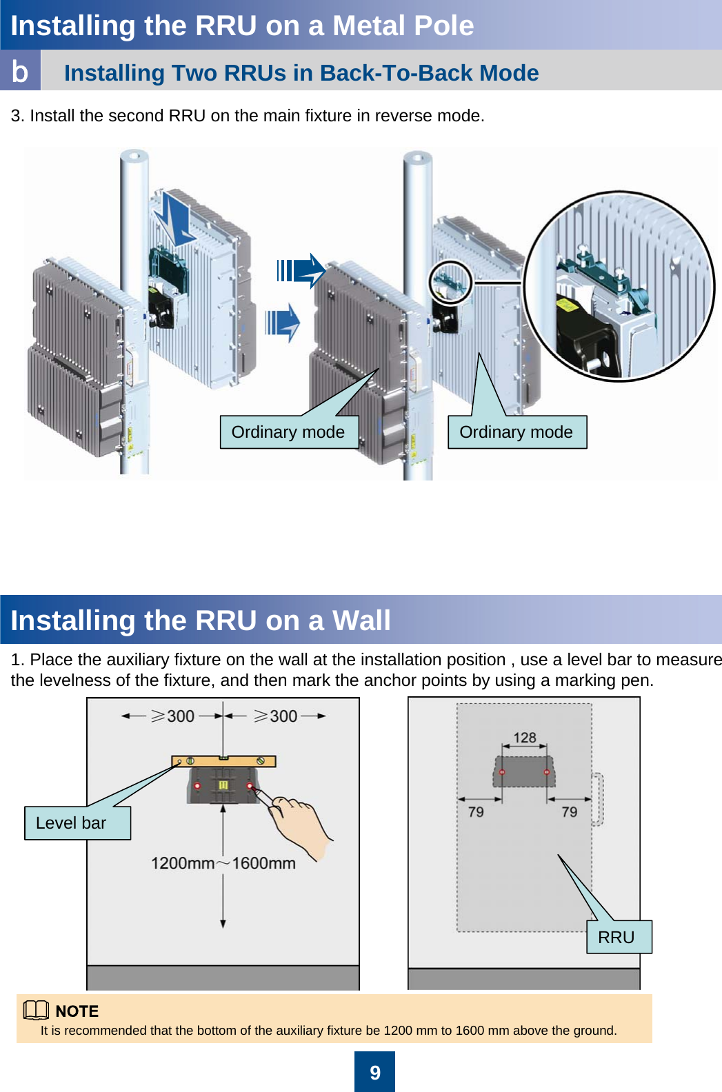
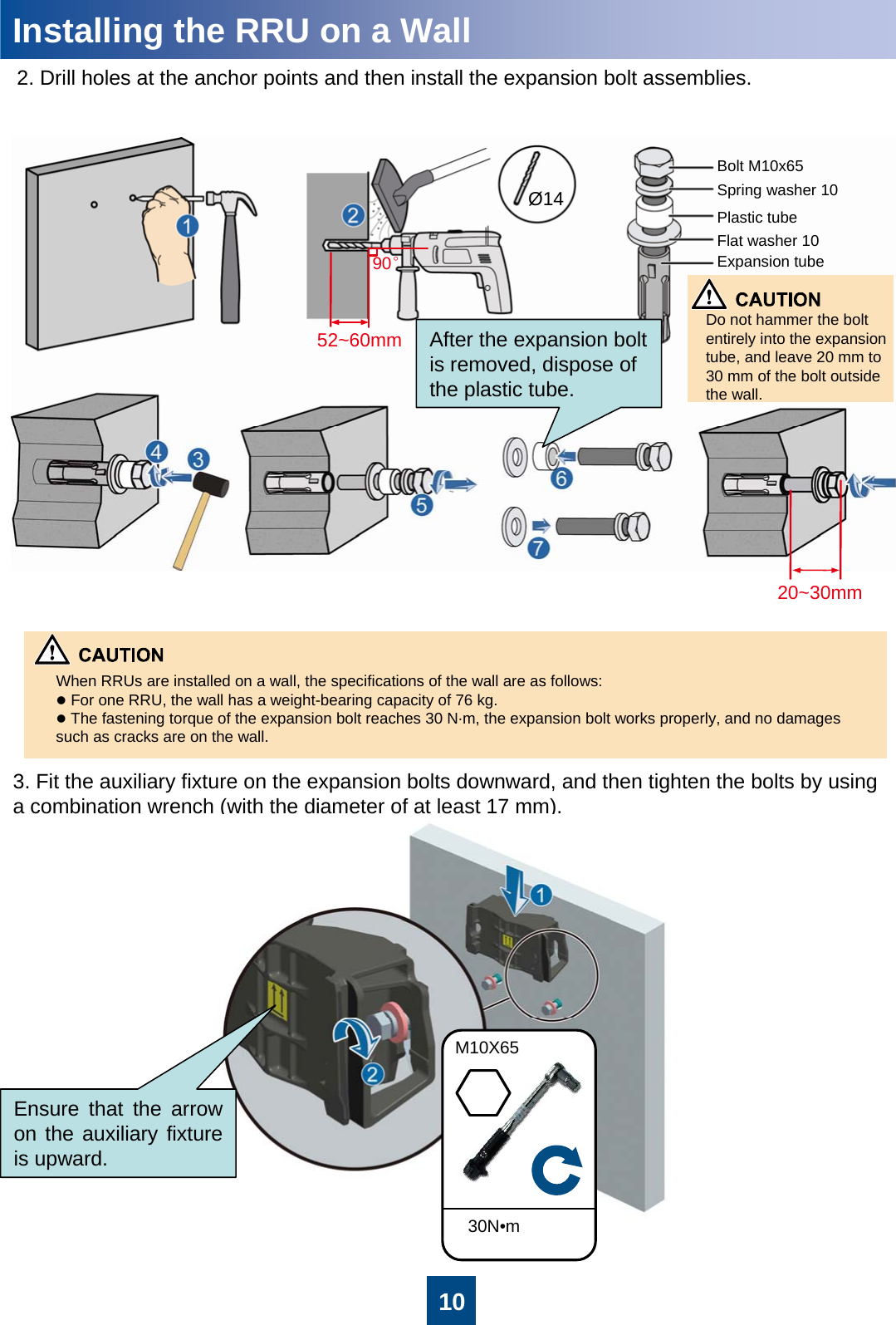
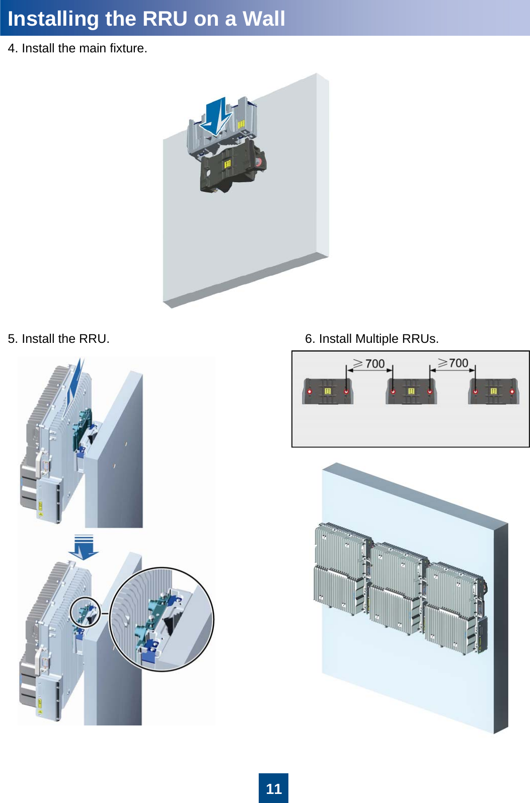
Installation Guide 1