Huawei Technologies RRU3203 Distributed Base Station Remote Radio Unit User Manual Installation Guide
Huawei Technologies Co.,Ltd Distributed Base Station Remote Radio Unit Installation Guide
UserManual.wiki
>
Huawei Technologies
>
RRU3203 User Manual
Installation Guide
Navigation menu
Upload a User Manual
Namespaces
Wiki Guide
HTML
PDF
Info
Views
User Manual
Discussion / Help
Navigation
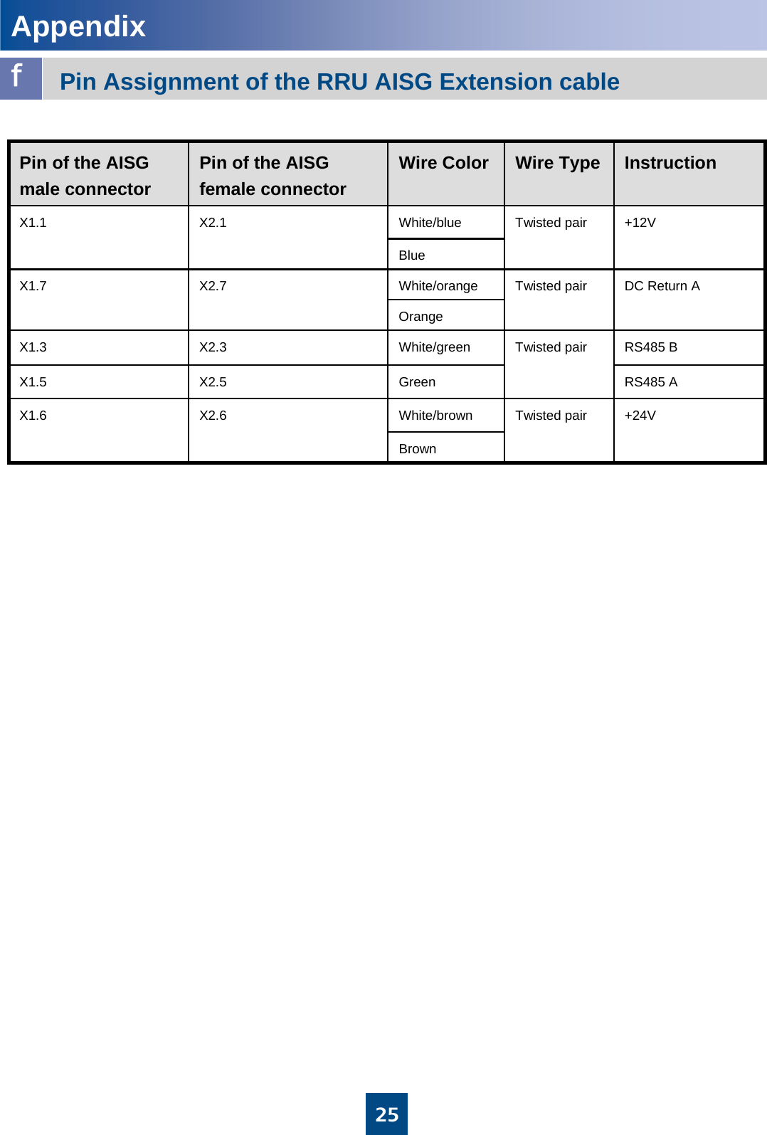
![2MultimeterKnifeHammer drill (with bit 14) Vacuum cleanerClaw hammerESD glovesHeat gunFlat-head screwdriver(M3~M6)Wire stripperWire cutterPower cable crimping pliersAdjustable wrench(with the diameter of at least 32 mm [1.3 in.])Torque screwdriverMeasuring tapeLevelMarking pen(with the diameter of no more than 10 mm [0.4 in.])Combination wrench(21mm~21mm) for pole installation(17mm~17mm) for wall installationPhillips screwdriver(M3~M6)Torque wrenchTorque socketInstallation Tools](https://usermanual.wiki/Huawei-Technologies/RRU3203/User-Guide-1278424-Page-3.png)
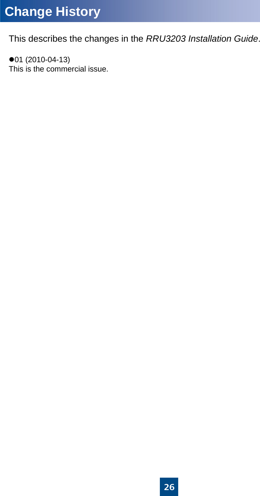
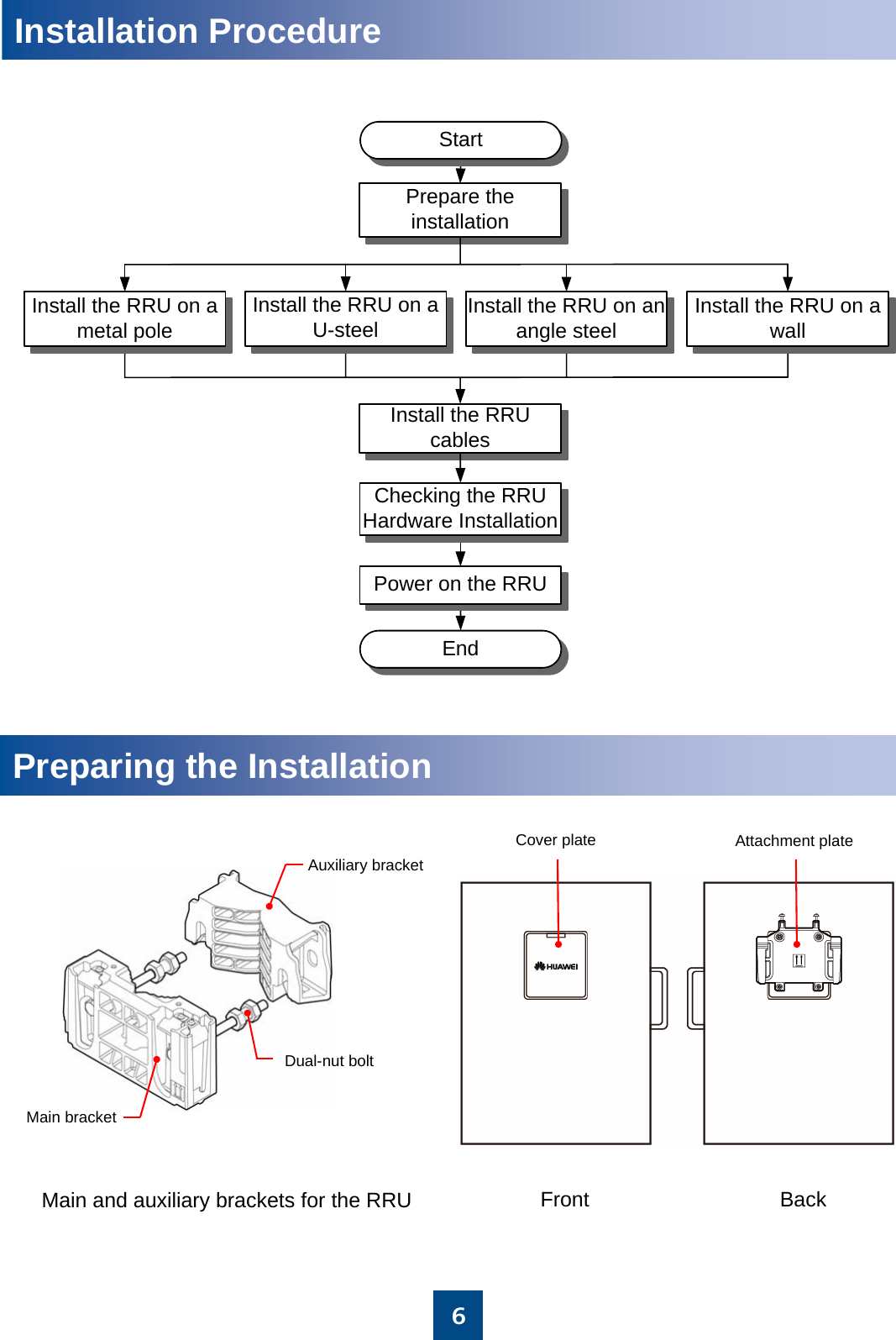
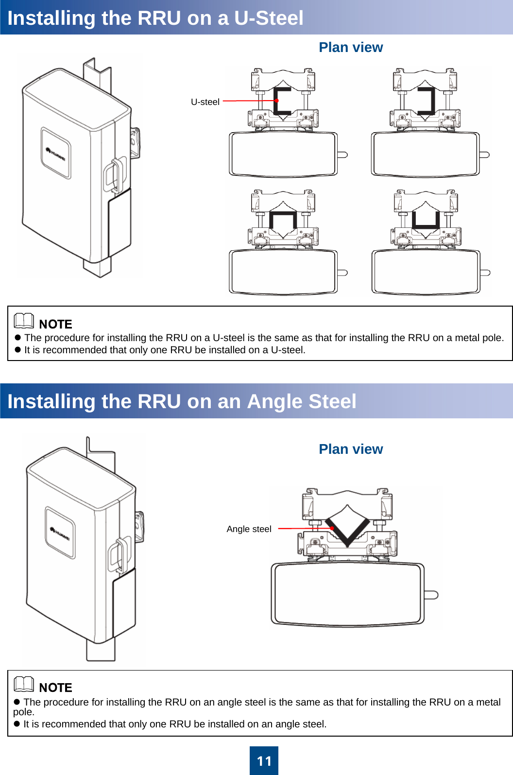
![360 mm [2.4 in.] to 114 mm [4.5 in.] 63mm~80mm63 mm [2.5 in.] to 75 mm [3 in.] ≤10°RRUAngle steel or U-steelOn a metal pole On a wallOn an angle steelOn a U-steelInstallation OptionsThe following figure describes the specifications for the metal pole, angle steel, and U-steel where the RRU is installed.Metal pole Angle steel U-steelThe brackets cannot be combined when the RRUsare installed on the wall.zA maximum of two RRUs can be installed on a metal pole with a diameter of 60 mm [2.4 in.] to 75 mm [3 in.] , and the installation mode must be standard mode. Three or more RRUs must be installed on a metal pole with a diameter of 76 mm [3 in.] to 114 mm [4.5 in.] in a centralized way. zIt is recommended that only one RRU be installed on a U-steel or an angle steel.zWhen installed on a tower, one RRU can be installed only in standard mode or reverse mode rather than side-mounted. Two RRUs cannot be installed in back-to-back mode.The angle between the vertical and the angle steel or U-steel or angle steel where the RRU is installed must be less than or equal to 10 degree.63 mm [2.5 in.] to 75 mm [3 in.] 50 mm [2 in.] to 100 mm [3.9 in.] 30 mm [1.2 in.] to 50 mm [2.0 in.]](https://usermanual.wiki/Huawei-Technologies/RRU3203/User-Guide-1278424-Page-4.png)
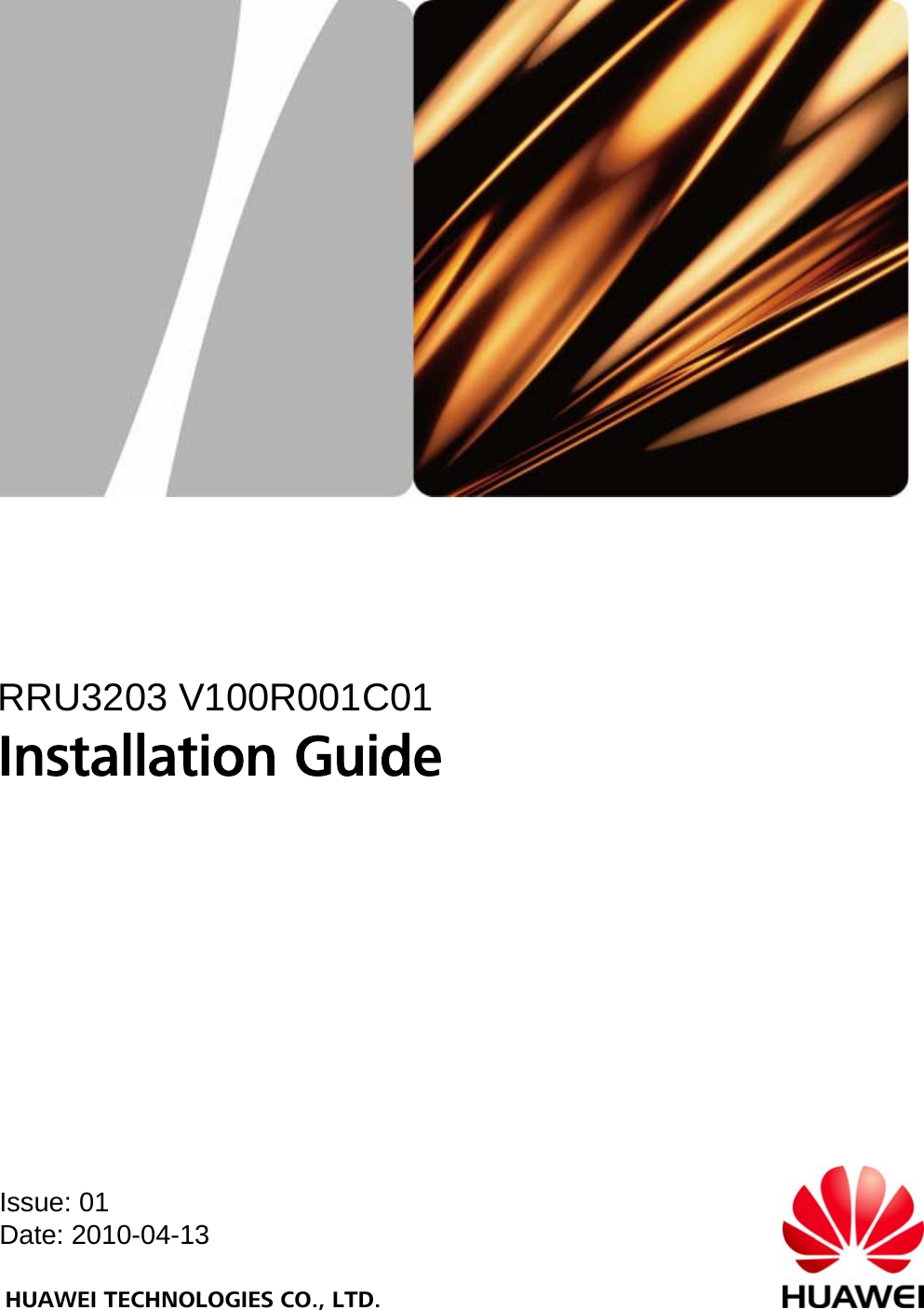
![4Dimensions and Installation Clearance≥300 mm [11.8 in.] ≥500 mm [19.7 in.] ≥800 mm [31.5 in.] ≥600 mm [23.6 in.] ≥300 mm [11.8 in.] a381 mm [15.0 in.] 170 mm [6.7 in.] 485 mm [19.1 in.] Dimensions of the RRUbRecommended Clearance for a Single RRUdRecommended Clearance for Multiple Centralized RRUs eMinimum Clearance for Multiple Centralized RRUscMinimum Clearance for a Single RRU200 mm [7.9 in.] 300 mm [11.8 in.] 400 mm [15.7 in.] 100 mm [3.9 in.] 600 mm [23.6 in.] ≥800 mm [31.5 in.] ≥500 mm [19.7 in.] ≥300 mm [11.8 in.] ≥500 mm [19.7 in.] ≥500 mm [19.7 in.] 300 mm [11.8 in.] 300 mm [11.8 in.] 200 mm [7.9 in.] 300 mm [11.8 in.] 600 mm [23.6 in.]](https://usermanual.wiki/Huawei-Technologies/RRU3203/User-Guide-1278424-Page-5.png)
![5Dimensions and Installation Clearancef gRecommended Horizontal Spacing for Two RRUs Installed in Parallel Minimum Horizontal Spacing for Two RRUs Installed in ParallelhiRecommended Vertical Spacing for Two RRUs Installed in Parallel Minimum Vertical Spacing for Two RRUs Installed in Parallel≥300 mm [11.8 in.] ≥500 mm [19.7 in.] ≥500 mm [19.7 in.] 200 mm [7.9 in.] 300 mm [11.8 in.] 300 mm [11.8 in.] ≥300 mm [11.8 in.] ≥600 mm [23.6 in.] ≥600 mm [23.6 in.] 100 mm [3.9 in.] 400 mm [15.7 in.] 400 mm [15.7 in.]](https://usermanual.wiki/Huawei-Technologies/RRU3203/User-Guide-1278424-Page-6.png)
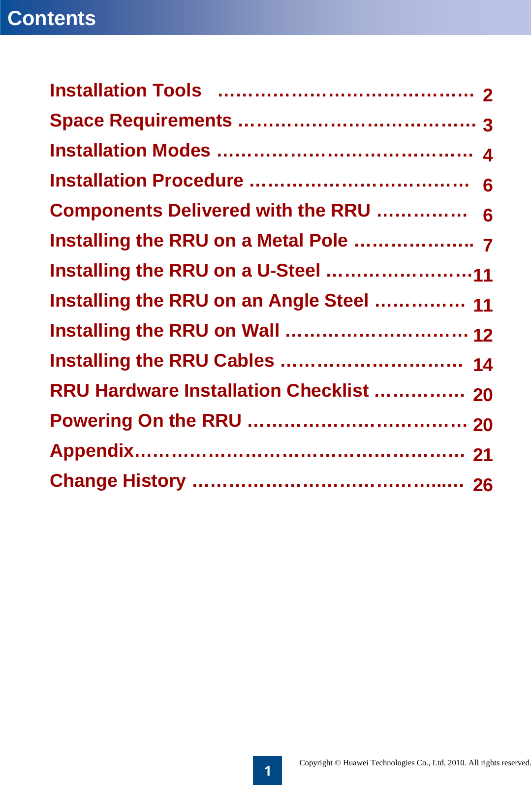
![71200 mm [47.2 in.]~1600 mm [63 in.]40 N•m[354 lbf•in.]When installing the main bracket, ensure that the contact piece on the bracket is fixed.You may fit one end of the auxiliary bracket on one dual-nut bolt assembly and then the other end on the other dual-nut bolt assembly during the installation.Fasten the two dual-nut bolt assemblies alternatively. After the brackets are secure, use a tape to measure the spacing between the main bracket and the auxiliary bracket at the two sides and ensure that the spacing is the same.zThe weight-bearing capacity of the RF ports at the bottom of the RRU is low. Do not place the RRU at its bottom.zDuring the operation, place the foam pad or cardboard under the RRU to prevent any damage to the housing of the RRU. 2. Use an adjustable wrench to tighten the nut until the fastening torque is 40 N·m [354 lbf•in.]. In this way, the main and auxiliary brackets are secured on the pole.1. Install the main bracket.Installing the RRU on a Metal PoleaInstalling a Single RRU on a Metal Pole3. Install the RRU on the main bracket. When you hear click sound, you can infer that the RRU is in position.](https://usermanual.wiki/Huawei-Technologies/RRU3203/User-Guide-1278424-Page-8.png)
![8Cabling cavityIn standard modeIn reverse modeInstalling the RRU on a Metal PoleInstalling Two RRUs Back-To-Back on a Metal Poleb4. Install the second RRU on the main bracket.3. Reinstall the attachment plate and cover plate on the second RRU by interchanging their positions.1. Install an RRU. For details, see page 7Installing a Single RRU on a Metal Pole.2. Install the main fixture for another RRU.Ensure that the cabling cavities of the two RRUs face the same direction when installing the RRUs.M6X164.8 N•m[42.5 lbf•in.]](https://usermanual.wiki/Huawei-Technologies/RRU3203/User-Guide-1278424-Page-9.png)
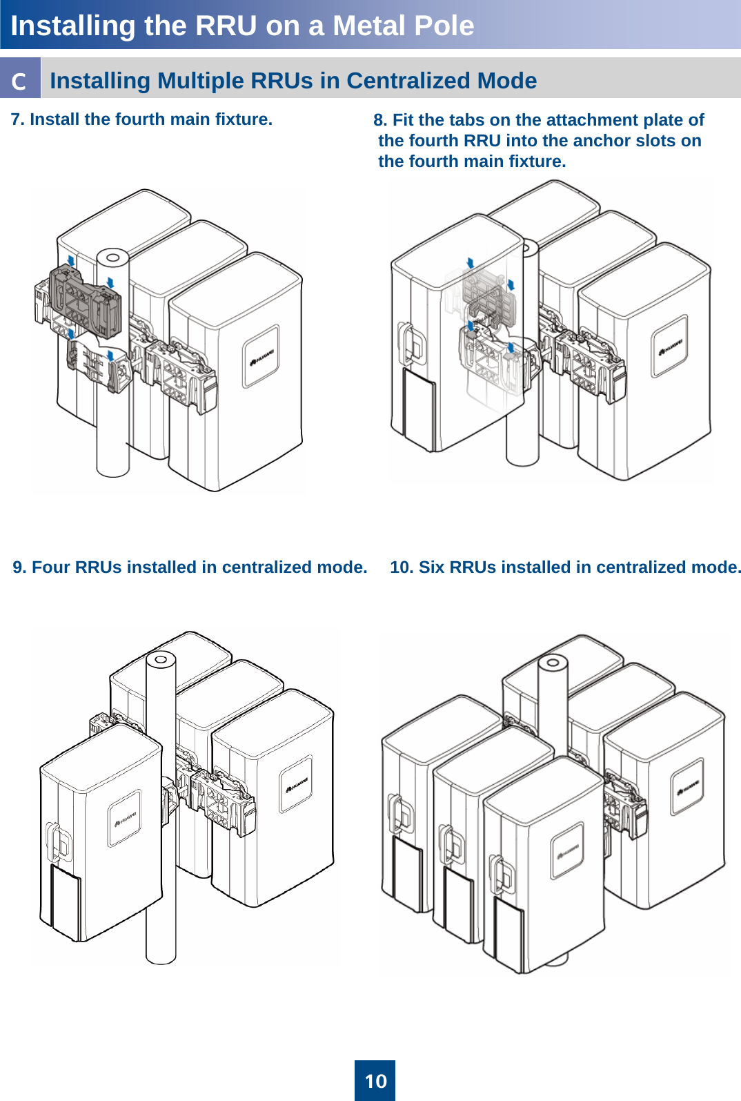
![9Installing the RRU on a Metal PoleInstalling Multiple RRUs in Centralized Modec2. Relocate the attachment plate.1. Install the main fixture and the auxiliary fixture. For details, see page 7 Installing a Single RRU in Ordinary Mode.4. Install the second main fixture.3. Fit the tabs on the attachment plate of theRRU into the anchor slots on the main fixture.5. Fit the tabs on the attachment plate ofthe second RRU into the anchor slots onthe second main fixture.6. Install the third RRU.M6X164.8 N•m[42.5 lbf•in.]](https://usermanual.wiki/Huawei-Technologies/RRU3203/User-Guide-1278424-Page-10.png)
![121200 mm [47.2 in.]to 1600 mm [63.0 in.]≥650 mm [25.6 in.] 128 mm[5 in.]RRULevelØ14After the expansion bolt is removed, dispose of the plastic tube.90°Installing the RRU on a Wall1. Place the auxiliary bracket at the installation position. Use a level to check that the auxiliary bracket is placed horizontally. Then, mark the anchor points by using a marking pen.zIt is recommended that the auxiliary bracket be 1,200 mm [47.2 in.] to 1,600 mm [63.0 in.] above the ground.zThe RRUs cannot installed on a wall in centralized mode. Therefore, expansion bolt assemblies should be prepared for each RRU.2. Drill holes at the anchor points and then install the expansion bolt assemblies.When the RRU is installed on a wall, the requirements are as follows:zFor one RRU, the wall has a weight-bearing capacity of 96 kg [211.7 lb].zThe fastening torque of the expansion bolt reaches 30 N•m [265.5 lbf•in.] the expansion bolt works properly, and no damages such as cracks are on the wall. M10x65 boltSpring washer 10Plastic tubeFlat washer 10Expansion tubeDo not hammer the bolt entirely into the wall. Instead, leave 20 mm to 30 mm of the bolt outside the wall.≥650 mm [25.6 in.]126.5 mm[5 in.] 126.5 mm[5 in.]20 mm [0.8 in.]to 30mm [1.2 in.]55 mm [2.2 in.]to 60mm [2.4 in.]](https://usermanual.wiki/Huawei-Technologies/RRU3203/User-Guide-1278424-Page-13.png)
![13Arrows are upwards30 N•m[265.5 lbf•in.]M10Installing the RRU on a Wall3. Fit the auxiliary bracket on the expansion bolts downward, and then tighten the bolts by using a combination wrench 17 mm [0.7 in.].4. Install the main bracket.5. Install the RRU.](https://usermanual.wiki/Huawei-Technologies/RRU3203/User-Guide-1278424-Page-14.png)
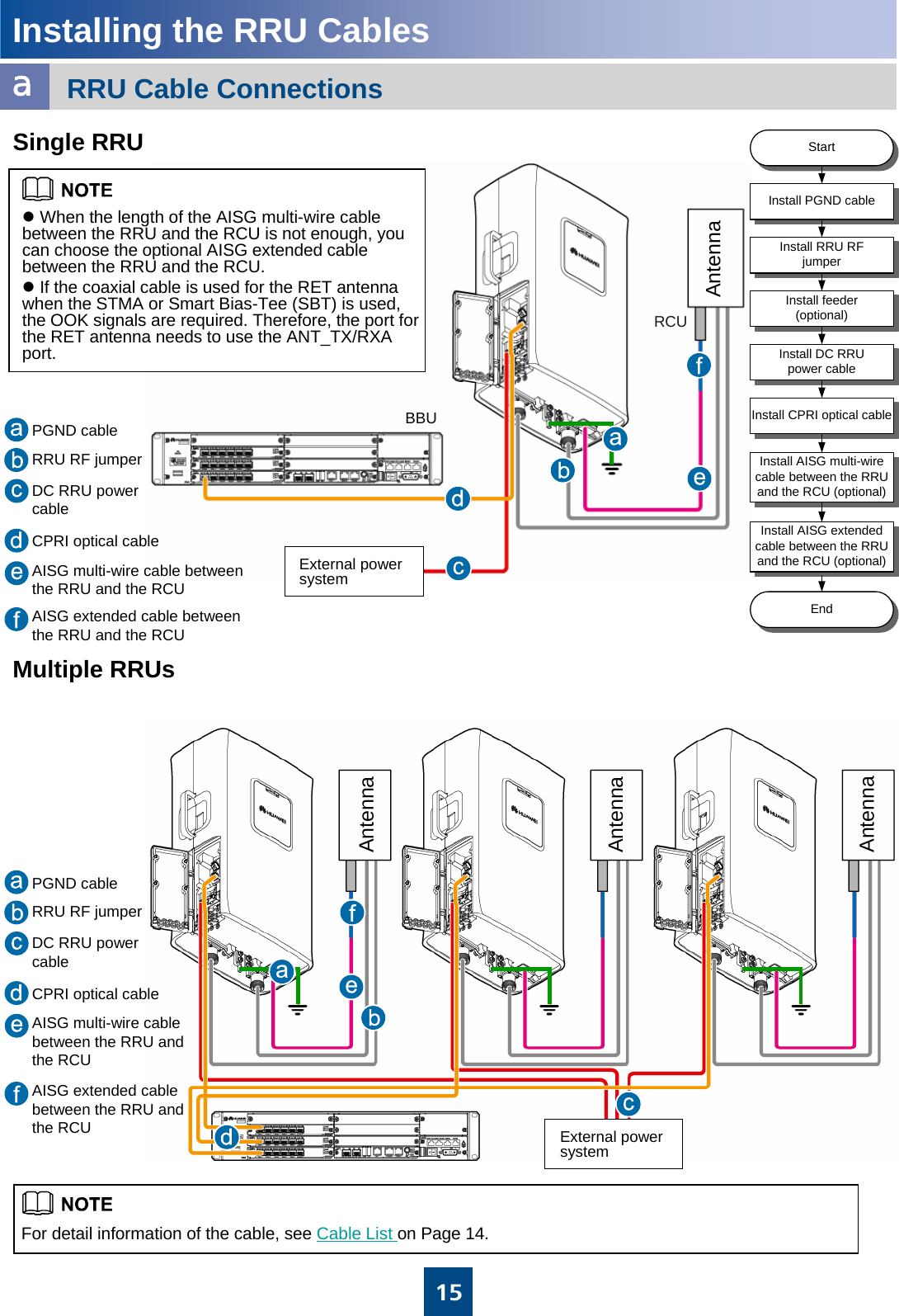
![14Installing the RRU on a Wall6. Install multiple RRUs.≥70 mm [2.8 in.]≥855 mm [33.7 in.]Minimum Clearance:Recommended Clearance :Installing the RRU CablesRRU Cable ConnectionsaStandard AISG female connector of the AISG multi-wire cableStandard AISG male connectorStandard AISG male connector of the AISG extension cable or RCUStandard AISG female connectorPort labeled RET/MON on the RRUWaterproof DB9 connectorAISG multi-wire cable between the RRU and the RCUThe connectors labeled 2A and 2B are connected to port labeled CPRI0 to CPRI5 on the LBBP board of the BBU.DLC connectorCPRI optical cable The connectors labeled 1A and 1B are connected to the optical module on the port labeled CPRI_W on the RRUDLC connectorAISG extended cable between the RRU and the RCU Standard AISG male connector of the RCUStandard AISG female connectorThe blue OT terminal is connected to socket labeled NEG(-)0 in the RRU cabling cavity. And the black OT terminal is connected to socket labeled RTN(+)0.Two OT terminals(M4)DC RRU power cable(North American standard: 3.3 mm2 European standard: 4 mm2 )External power supplyBare wireFeeder or antennaDIN male connectorPorts labeled ANT_TX/RXA and ANT_TX/RXB on the RRU(Only the ANT_TX/RXA port supports the OOK signal).DIN male connectorRRU RF jumperNearest grounding barOT terminalGrounding bolt on the RRUOT terminal (M6)PGND cable(16 mm2)Connector to…Connector TypeCableCable List≥855 mm [33.7 in.]≥655 mm [25.8 in.]≥655 mm [25.8 in.]≥70 mm [2.8 in.]](https://usermanual.wiki/Huawei-Technologies/RRU3203/User-Guide-1278424-Page-15.png)
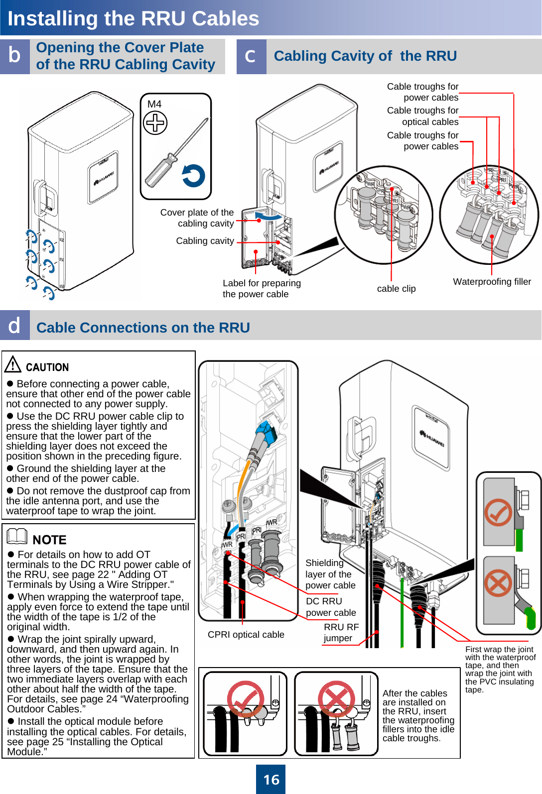
![17Installing the RRU CableseClosing the Cover Plate of the RRU Cabling CavityzThe screws on the cover plate should be tightened until the fastening torque is 1.4 N·m [12.4 lbf•in.].zTighten the screws on the cover plate of the cabling cavity in the sequence shown in the figure. fRRU+APM30HRRU1DC RRU power cableCPRI optical cableabDC RRU power cablezThe DC RRU power cable is connected to one of the RRU0 to RRU5 terminals of the PDU.zStrip the jacket of the DC RRU power cable for a small part, press the exposed shielding layer in the power cable clip, and then connect the PGND cable on the clip to the nearest grounding bolt on the side of the cabinet.M41.4 N•m[12.4 lbf•in.]Metal Shielding layer (25 mm [1 in.]) PGND cableGrounding the shielding layer of the power cable:](https://usermanual.wiki/Huawei-Technologies/RRU3203/User-Guide-1278424-Page-18.png)
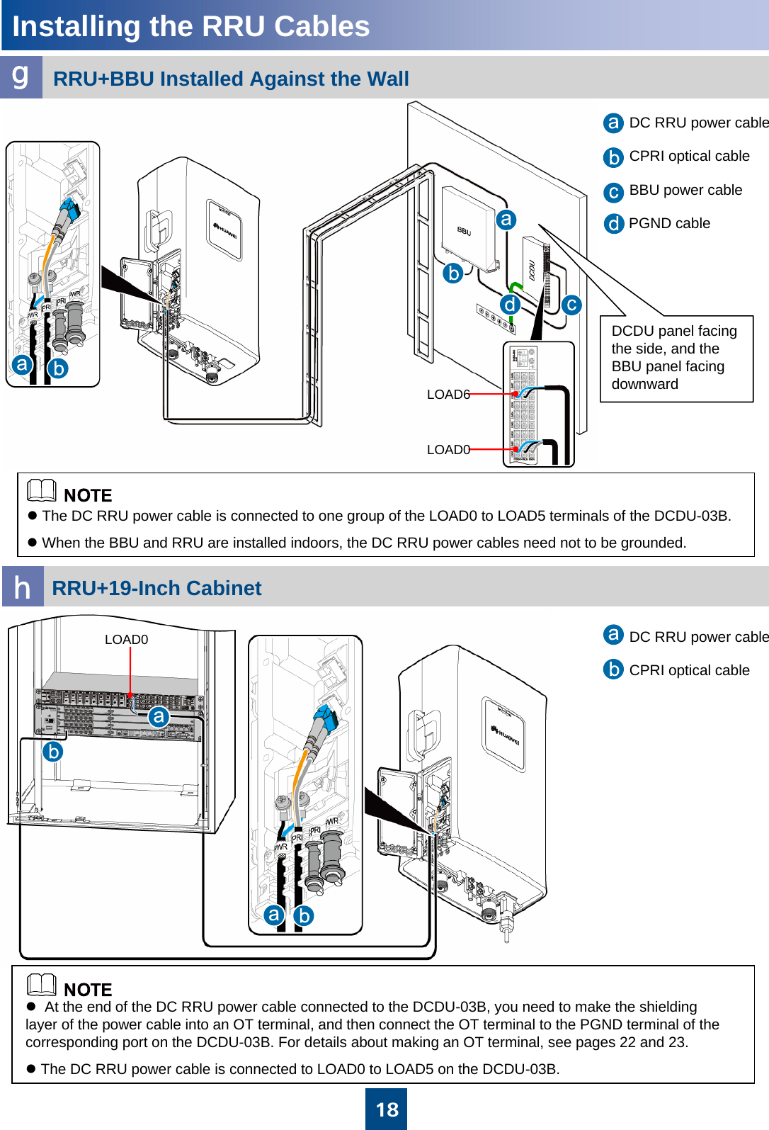
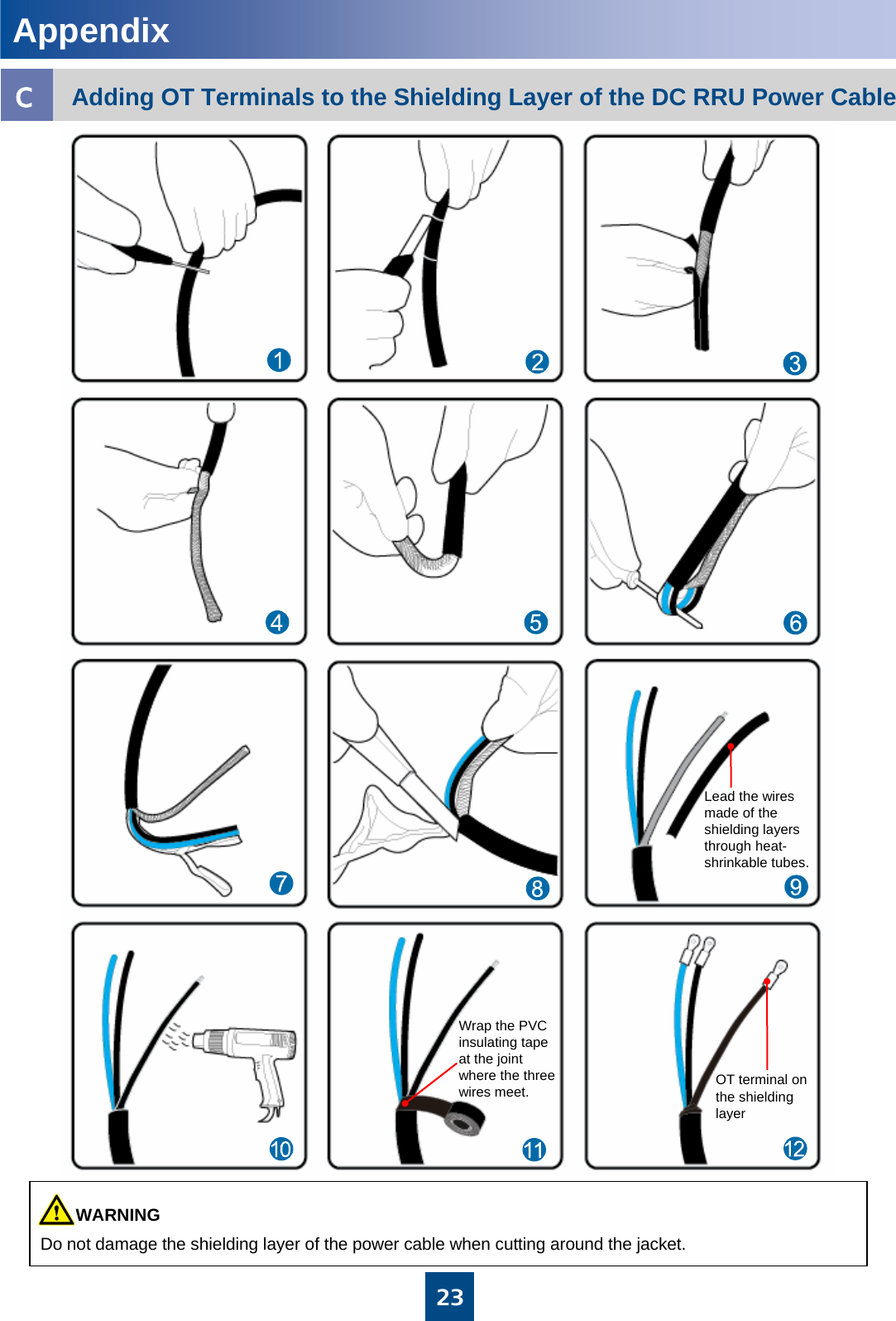
![19Installing the RRU CablesiRRU+TMC/TMC11HDC RRU power cableCPRI optical cableabLOAD0zAt the end of the DC RRU power cable connected to the DCDU-03B, you need to make the shielding layer of the power cable into an OT terminal, and then connect the OT terminal to the PGND terminal of the corresponding port on the DCDU-03B. For details about making an OT terminal, see pages 22 and 23. zThe DC RRU power cable is connected to LOAD0 to LOAD5 on the DCDU-03B. Metal Shielding layer (25 mm [1 in.]) PGND cableGrounding the shielding layer of the power cable:DC RRU power cable](https://usermanual.wiki/Huawei-Technologies/RRU3203/User-Guide-1278424-Page-20.png)
![20abStartCheck whether the input voltage of the RRU is normal?EndPower on the RRUCheck whether the status of the LEDs on the RRU is normal?Rectify the faultRectify the faultYesNoaNormal input voltage of the RRU:If the BBU is supplied with -48 V DC power, the external input power voltage ranges from -57 V DC to -36 V DC.Normal status of the LEDs on the RRU:RUN LED: ON for 1s and OFF for 1sALM LED: OFFbYesNoRRU Hardware Installation ChecklistPowering on the RRUWhen the RRU is unpacked, it must be powered on within 24 hours. There are no connectors or joints on the power cable or PGND cable.5The connector of the signal cable is intact, and no damaged or broken parts exist on the cable.10Labels are correct, legible, and complete on both ends of each cable.11The power cable, PGND cable, feeder, optical cable and the E1/T1/FE signal cable are bound separately with a spacing of larger than 30 mm [1.2 in.] .9All the power cables and PGND cables are not short-circuited or reversely connected. In addition, no damaged or broken parts exist.8The flat washer and the spring washer are well mounted on all OT terminals.7The terminals at both ends of the power cable or PGND cable are securely soldered or crimped.6Waterproof fillers are installed in the idle cable troughs of the cabling cavity of the RRU, and the cover plate of the cabling cavity is securely installed. In addition, the idle RF ports are covered with waterproof caps and waterproofed.4The cover plate is securely installed on the cabling cavity of the RRU.3The RRU and the installation parts are securely installed.2All self-made PGND cables are copper-based with the proper wire diameters. No breaking device such as switch and fuse is allowed for the electric connection of the grounding system. No short circuit is allowed. Each terminal on the grounding bar can be connected with only one wiring terminal of the PGND cable.1ItemsNo.](https://usermanual.wiki/Huawei-Technologies/RRU3203/User-Guide-1278424-Page-21.png)
![24Waterproofing Outdoor CablesdzThe waterproof tape should be wrapped for an extra length of 20 mm [0.8 in.] away from the connectors at both ends. zThe tapes should be wrapped around the connector from the lower part to the upper part. When wrapped for another layer, the tapes may not be cut.zWhen wrapping the waterproof tape, apply even force to extend the tape until the width of the tape is 1/2 of the original width. zWhen wrapping the waterproof tape, ensure that the upper layer of the tape covers at least 50% of the lower layer. zThe insulating tape should be wrapped for an extra length of 20mm [0.8 in.] away from the connectors at both ends.zThe last layer of the waterproof tape should be wrapped from the lower part to the upper part to prevent rainwater from infiltrating into the tape. Waterproof tape Insulating tapeInstalling the Optical ModuleeTightly pressing the tape1. Wrap three layers of waterproof tape.2. Wrap three layers of insulating tape.Tightly pressing the tapeBinding cable ties at both ends of the tapetietieAppendix](https://usermanual.wiki/Huawei-Technologies/RRU3203/User-Guide-1278424-Page-25.png)