Huawei Technologies RRU3256-3600 Remote Radio Unit User Manual Installation Guide
Huawei Technologies Co.,Ltd Remote Radio Unit Installation Guide
UserManual.wiki
>
Huawei Technologies
>
RRU3256-3600 User Manual
>
Users Manual
Contents
1.
Users Manual
2.
Regulatory Compliance Statement
Users Manual
Navigation menu
Upload a User Manual
Namespaces
Wiki Guide
HTML
PDF
Info
Views
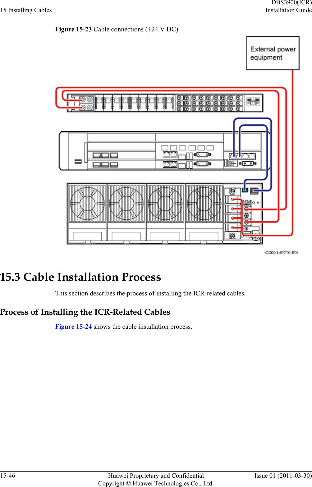
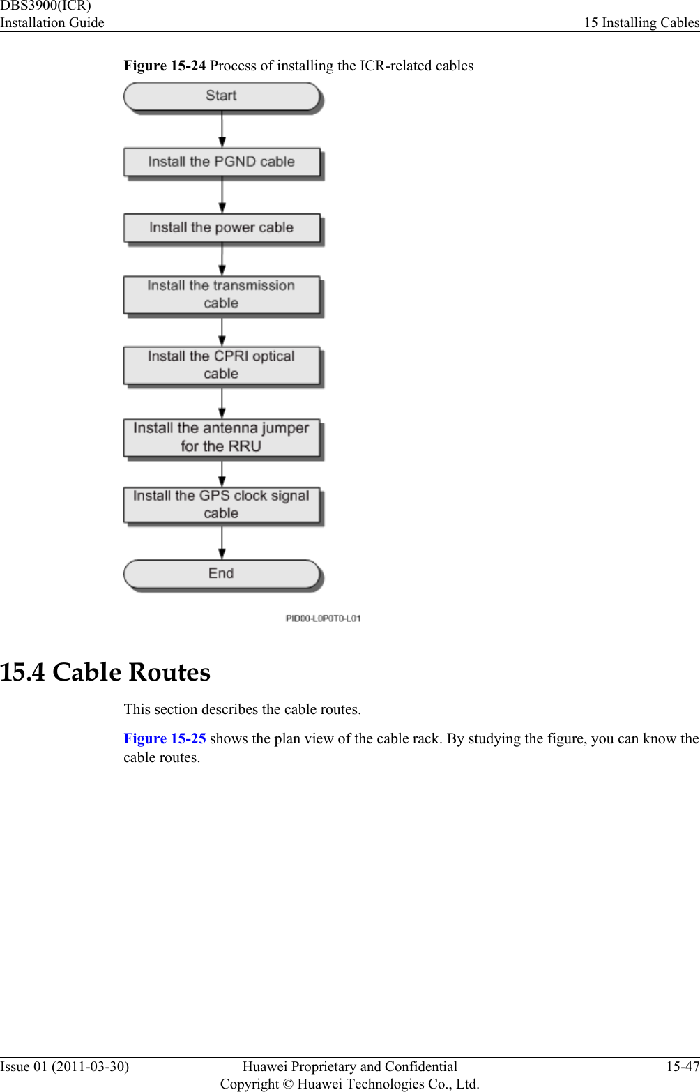
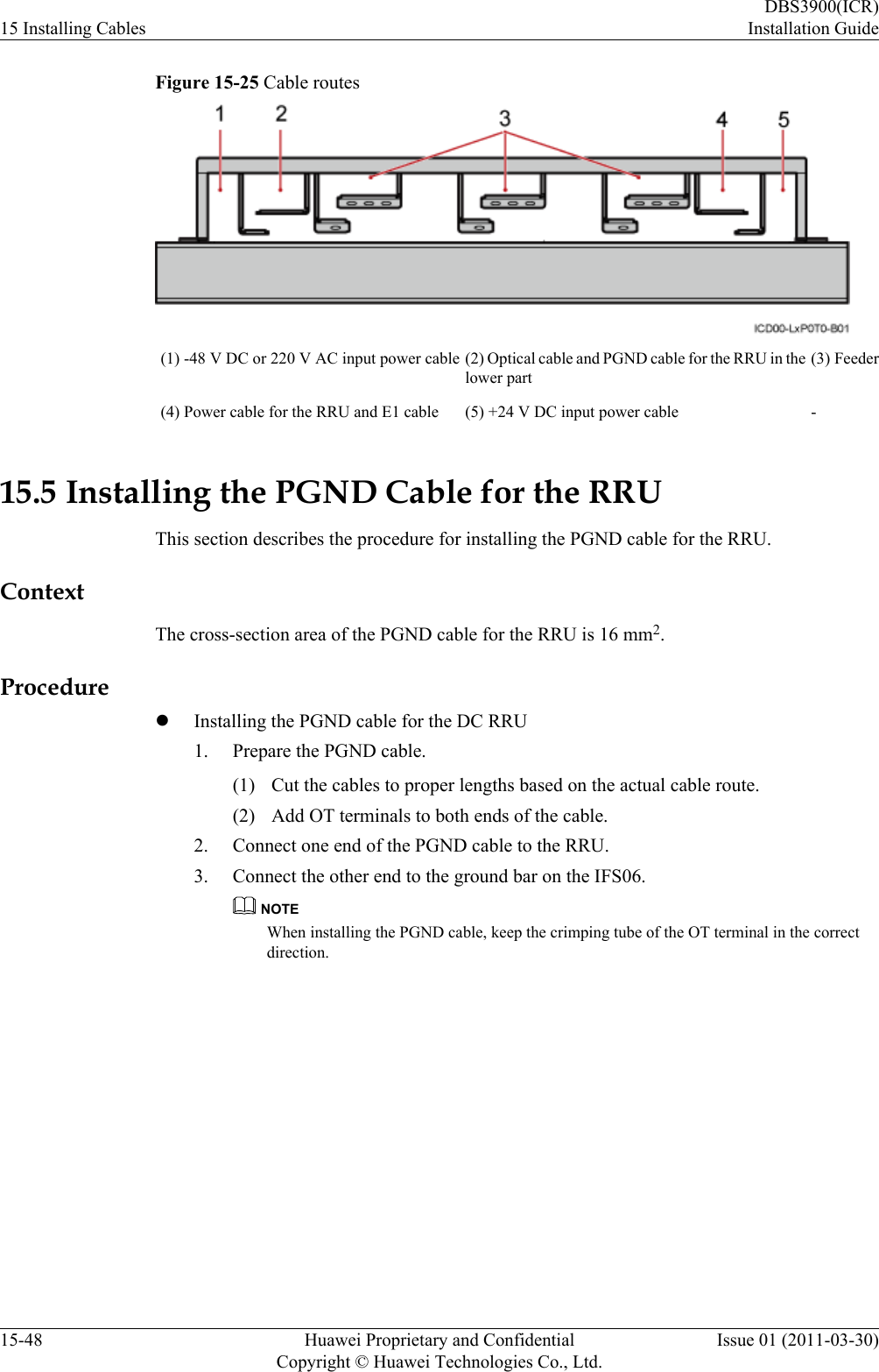
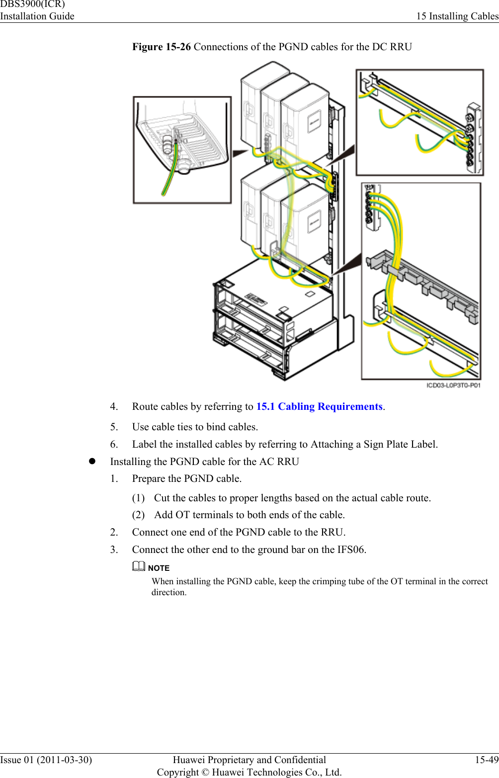
User Manual
Discussion / Help
Navigation
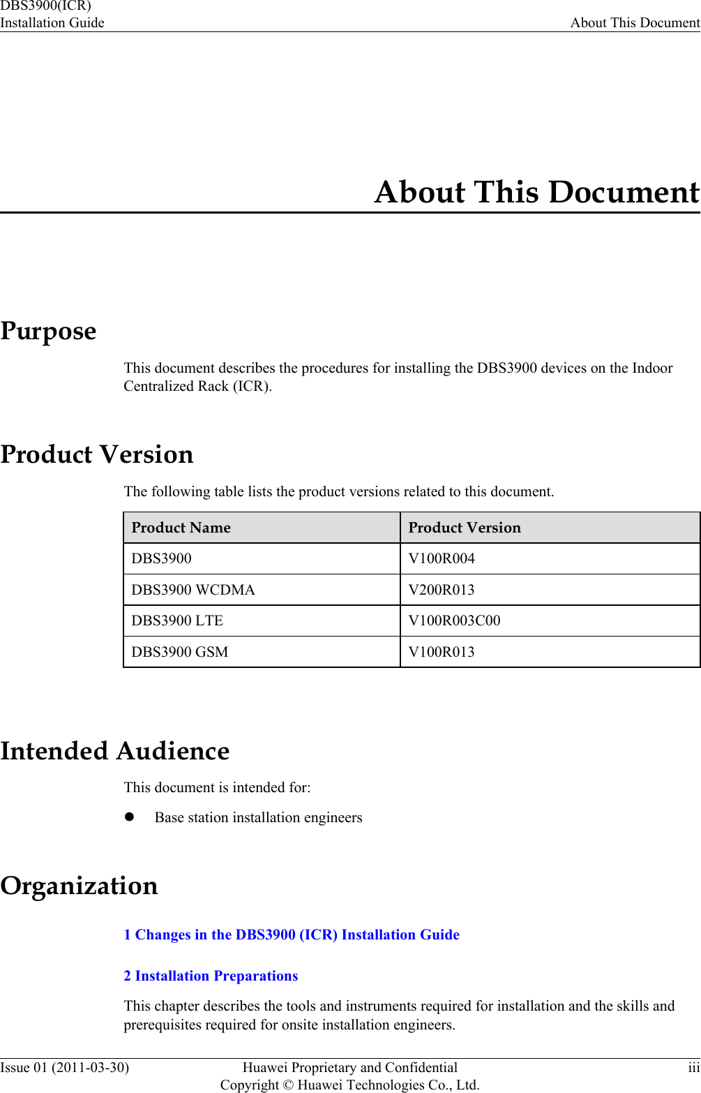
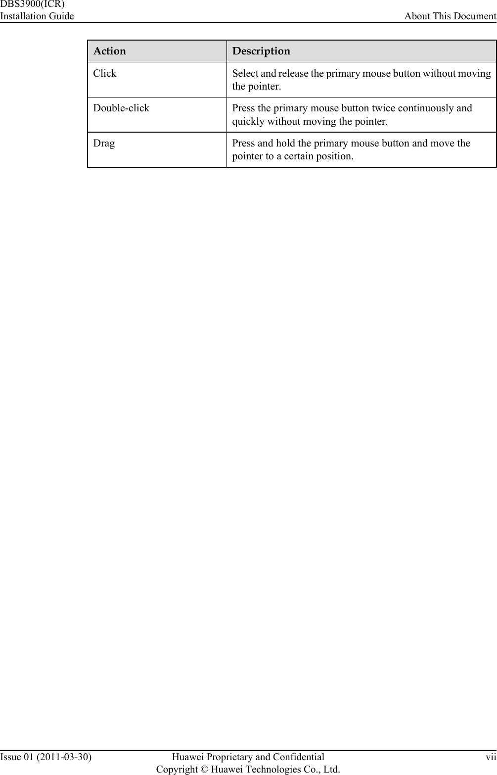
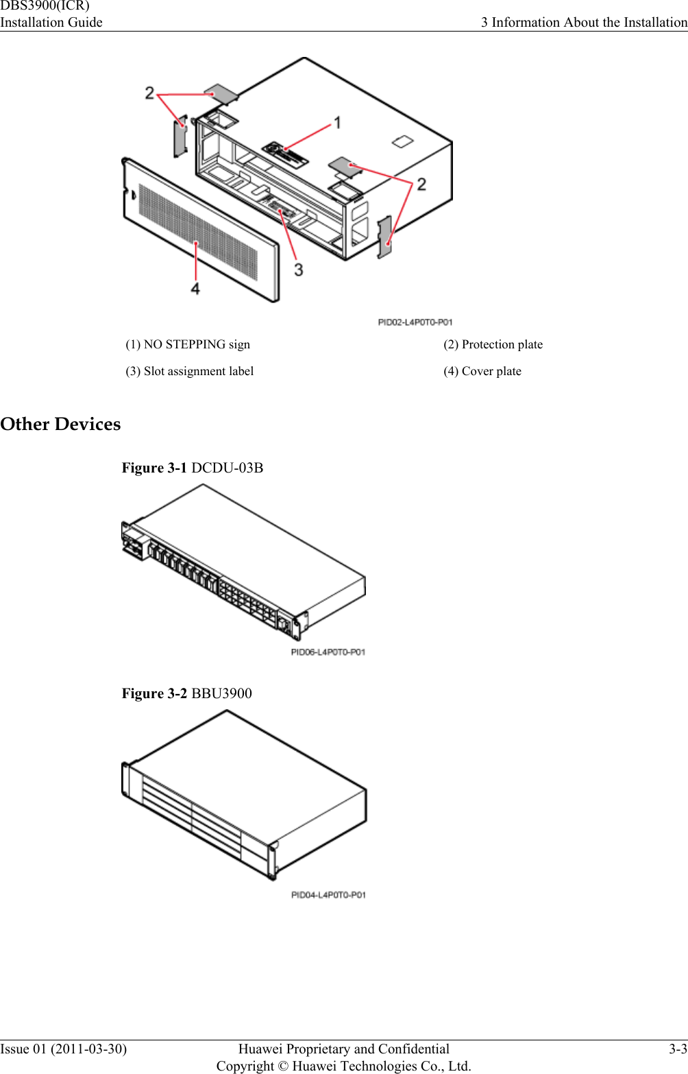
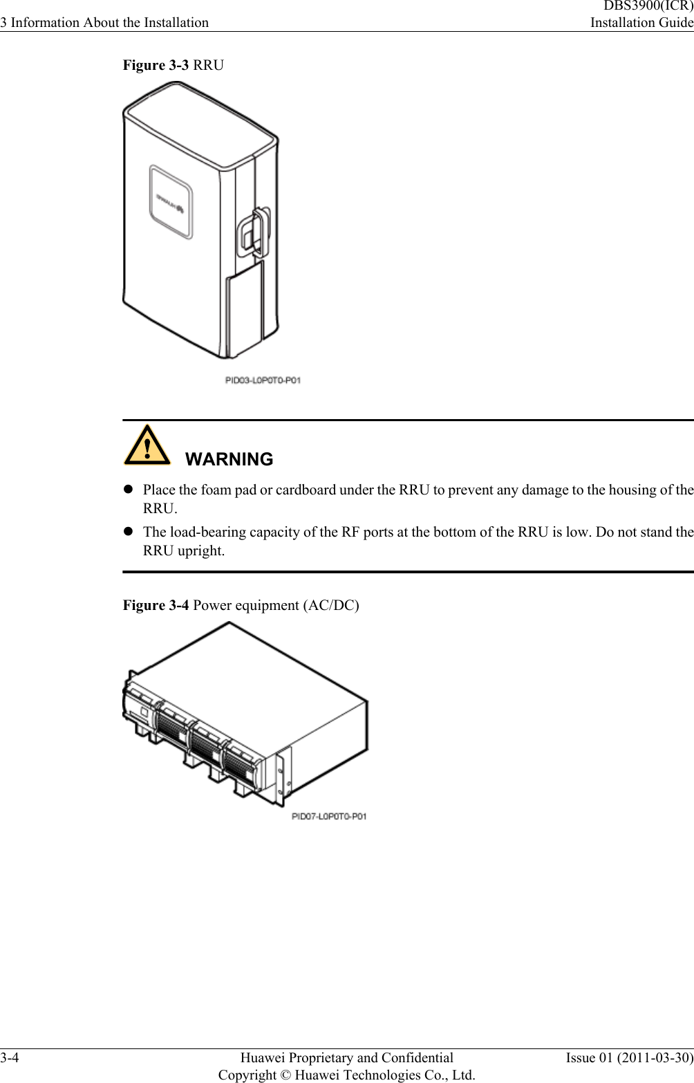
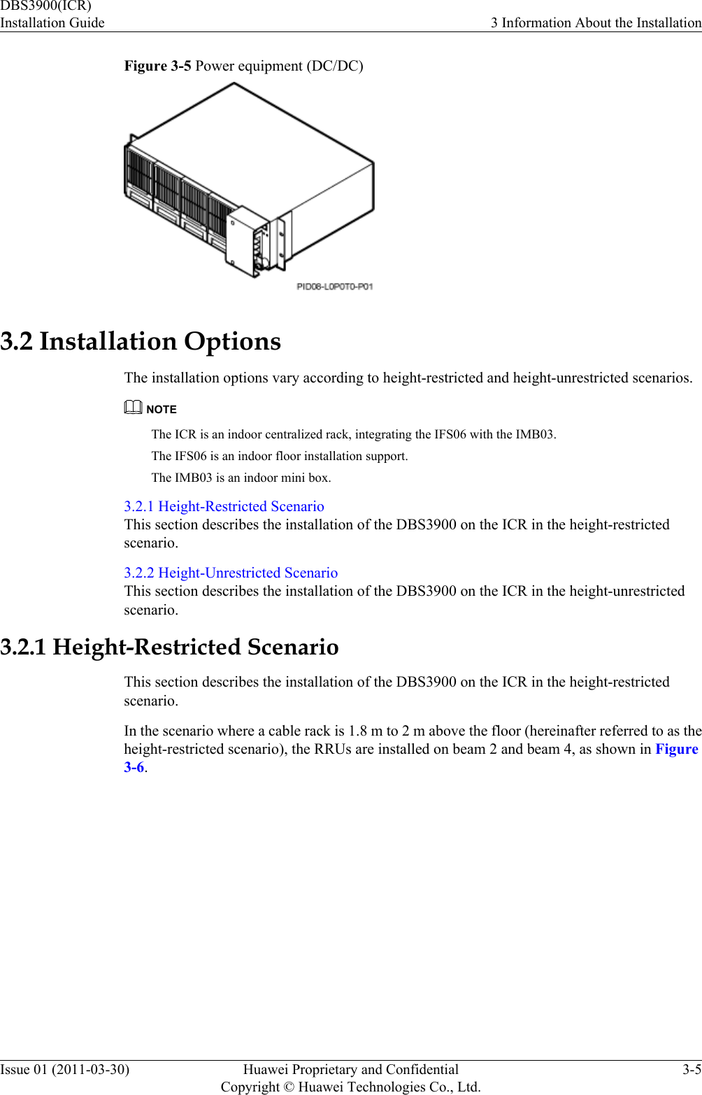
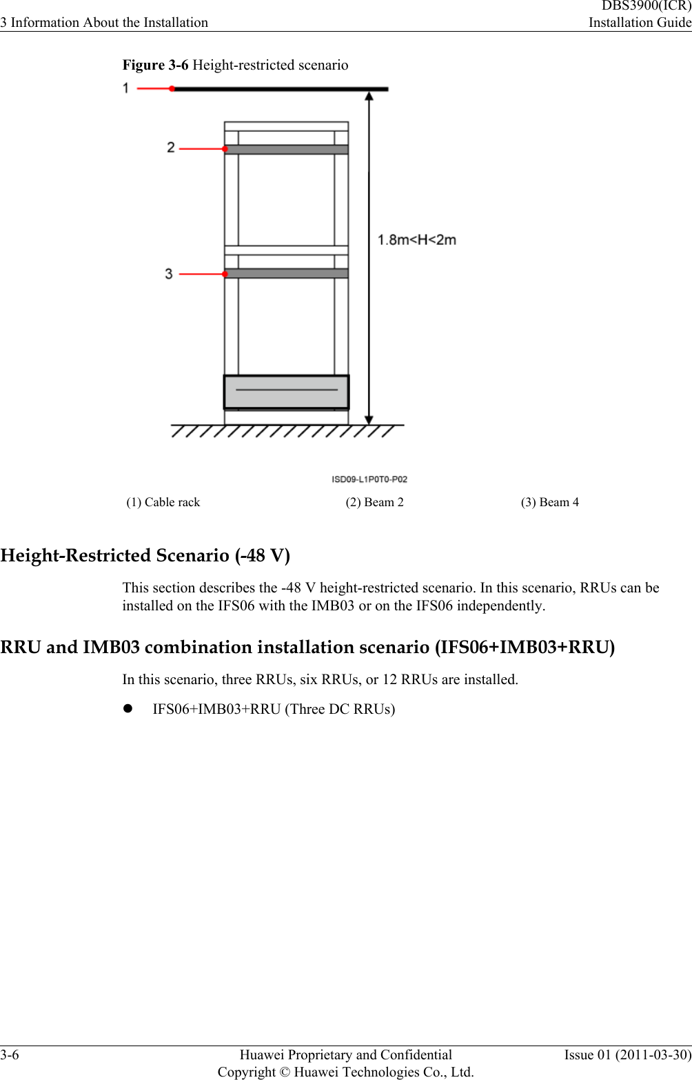
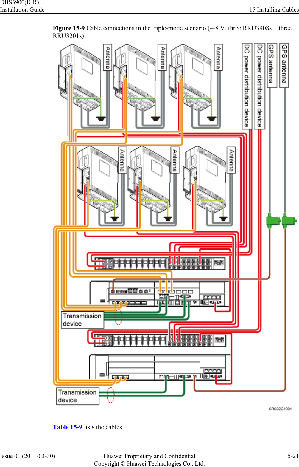
![Convention Description[ ] Items (keywords or arguments) in brackets [ ] are optional.{ x | y | ... } Optional items are grouped in braces and separated byvertical bars. One item is selected.[ x | y | ... ] Optional items are grouped in brackets and separated byvertical bars. One item is selected or no item is selected.{ x | y | ... }*Optional items are grouped in braces and separated byvertical bars. A minimum of one item or a maximum of allitems can be selected.[ x | y | ... ]*Optional items are grouped in brackets and separated byvertical bars. Several items or no item can be selected. GUI ConventionsThe GUI conventions that may be found in this document are defined as follows.Convention DescriptionBoldface Buttons, menus, parameters, tabs, window, and dialog titlesare in boldface. For example, click OK.>Multi-level menus are in boldface and separated by the ">"signs. For example, choose File > Create > Folder. Keyboard OperationsThe keyboard operations that may be found in this document are defined as follows.Format DescriptionKey Press the key. For example, press Enter and press Tab.Key 1+Key 2 Press the keys concurrently. For example, pressing Ctrl+Alt+A means the three keys should be pressed concurrently.Key 1, Key 2 Press the keys in turn. For example, pressing Alt, A meansthe two keys should be pressed in turn. Mouse OperationsThe mouse operations that may be found in this document are defined as follows.About This DocumentDBS3900(ICR)Installation Guidevi Huawei Proprietary and ConfidentialCopyright © Huawei Technologies Co., Ltd.Issue 01 (2011-03-30)](https://usermanual.wiki/Huawei-Technologies/RRU3256-3600.Users-Manual/User-Guide-2713982-Page-8.png)