Huawei Technologies RRU3260 Remote Radio Unit User Manual Installation Guide
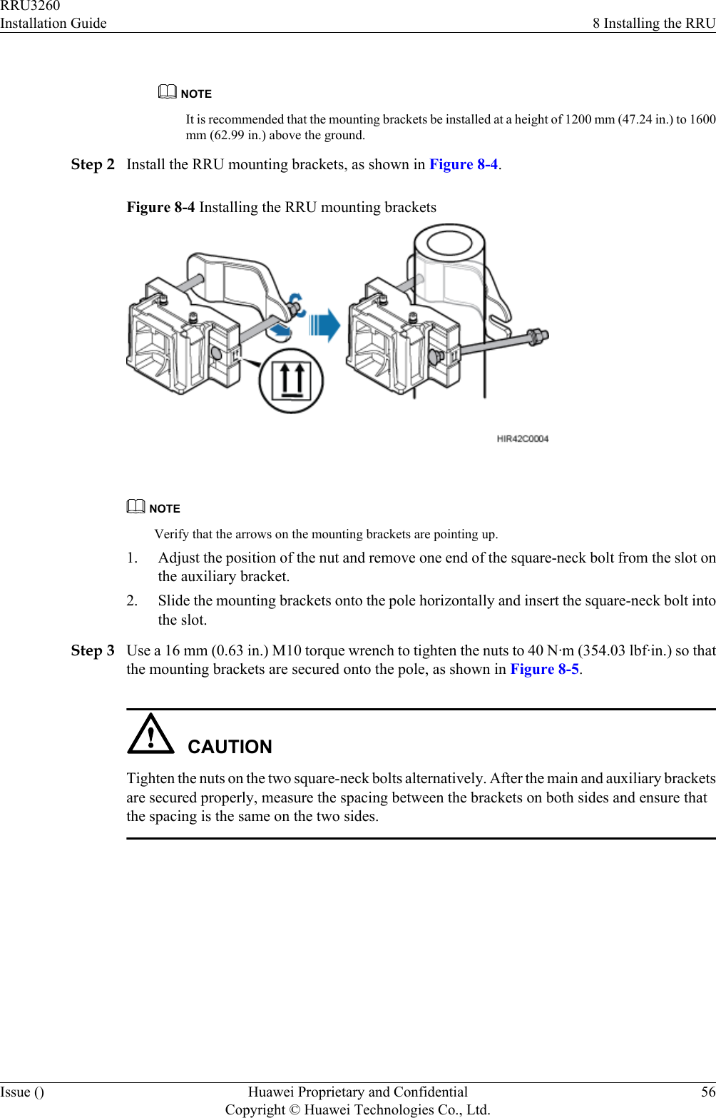
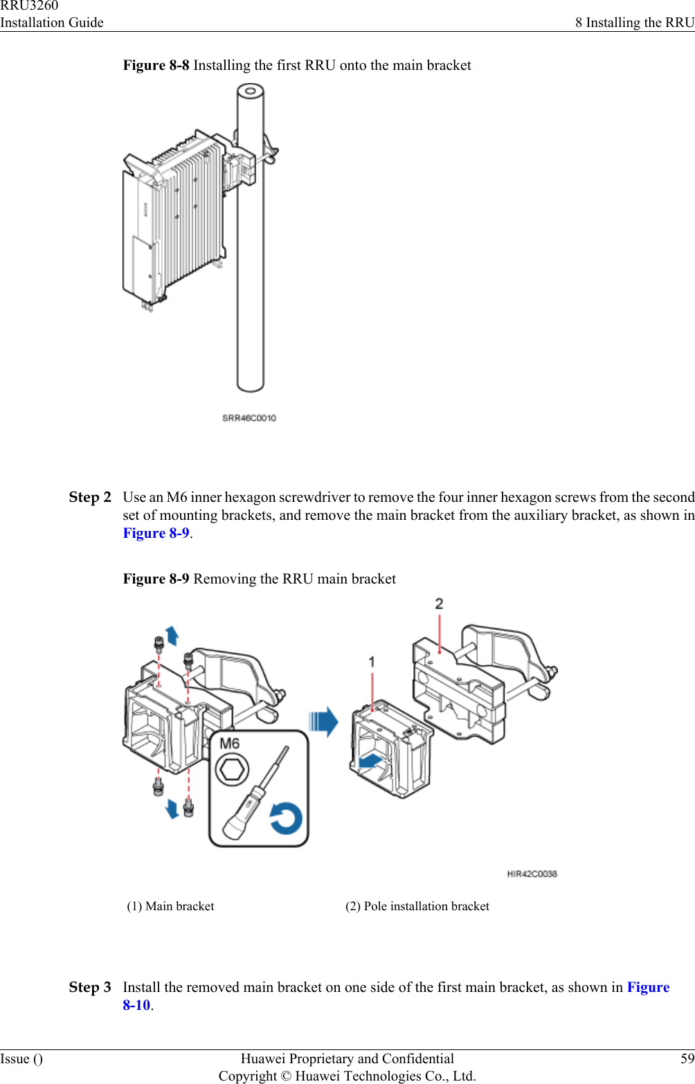
Huawei Technologies Co.,Ltd Remote Radio Unit Installation Guide
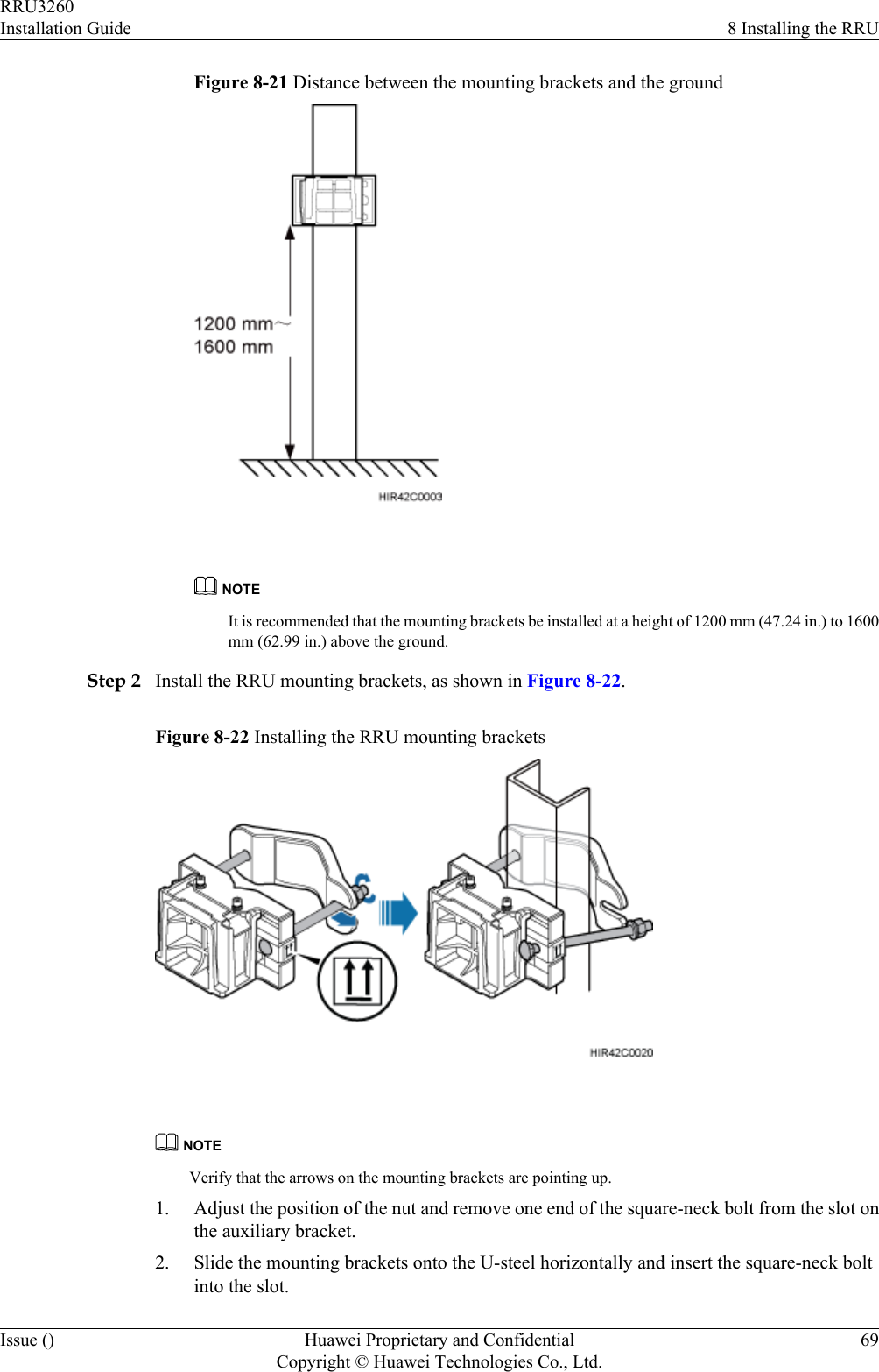
UserManual.wiki
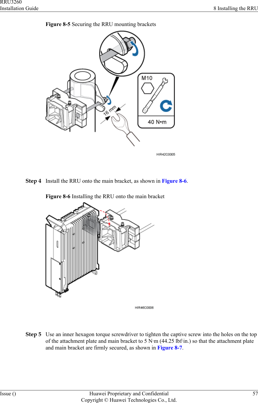
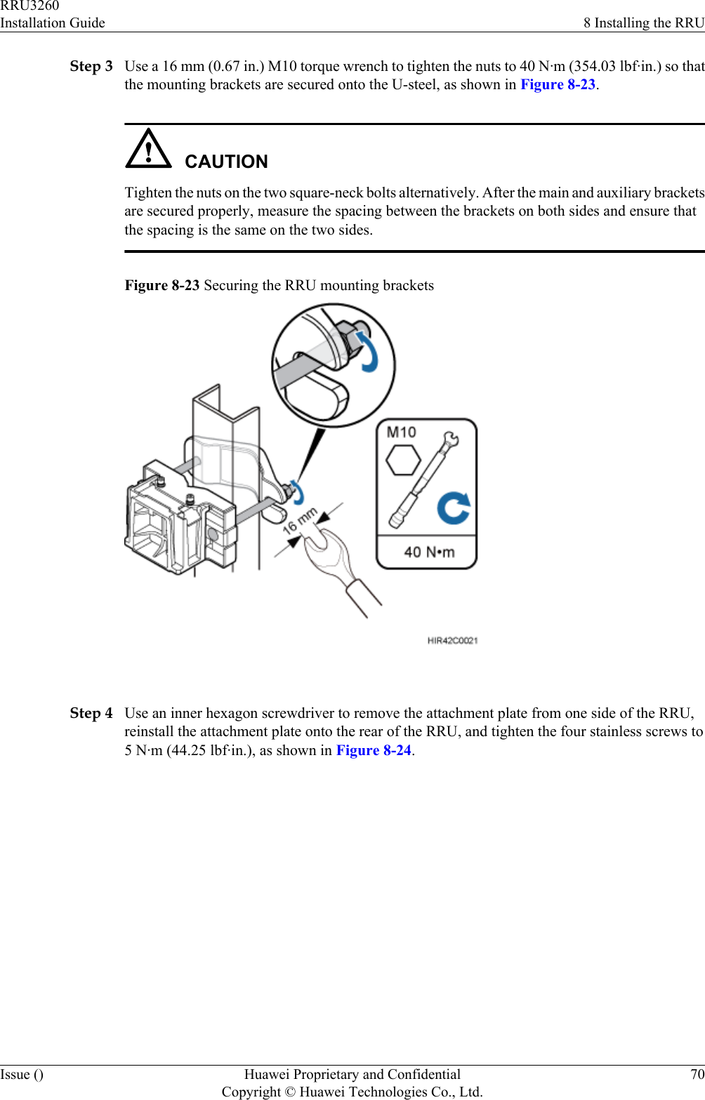
>
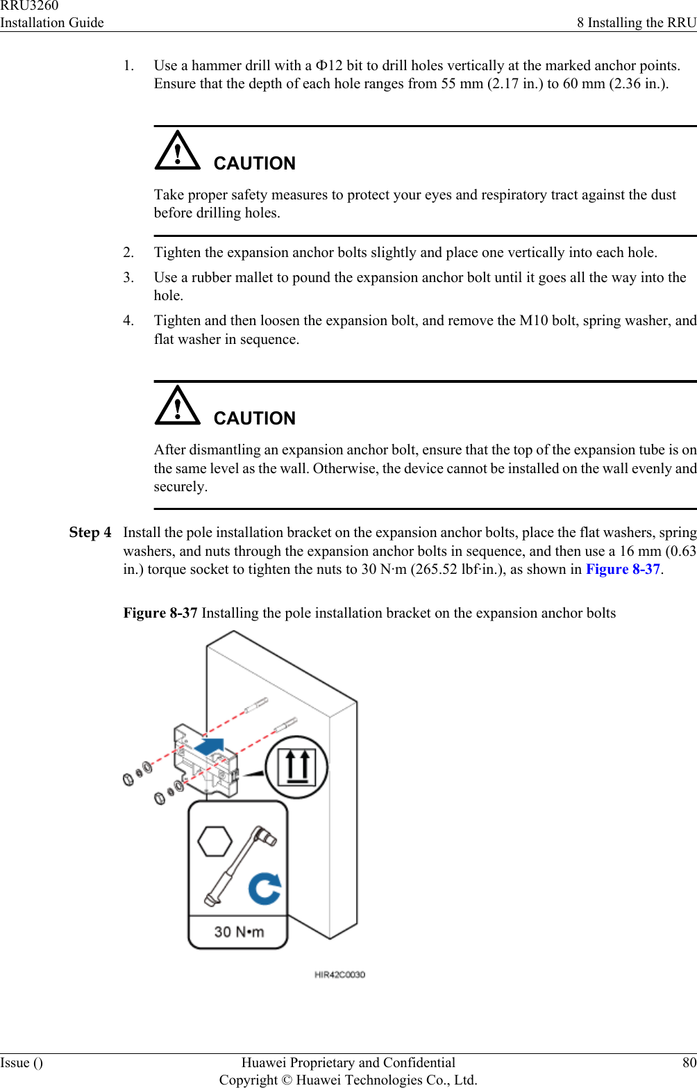
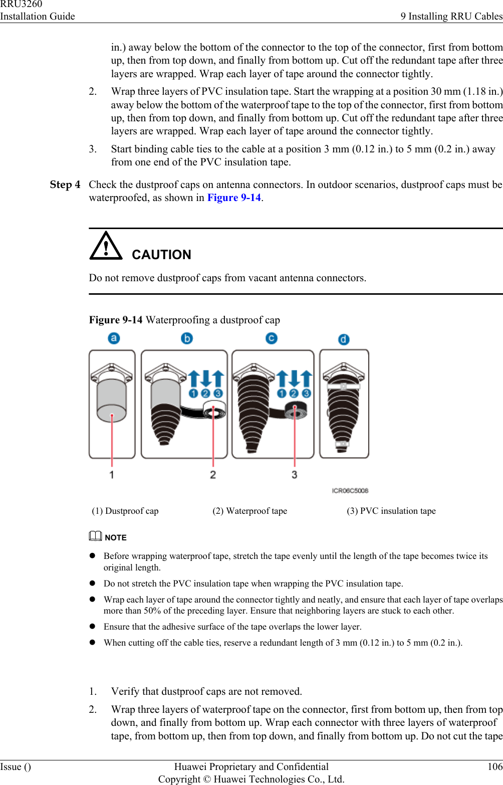
Huawei Technologies
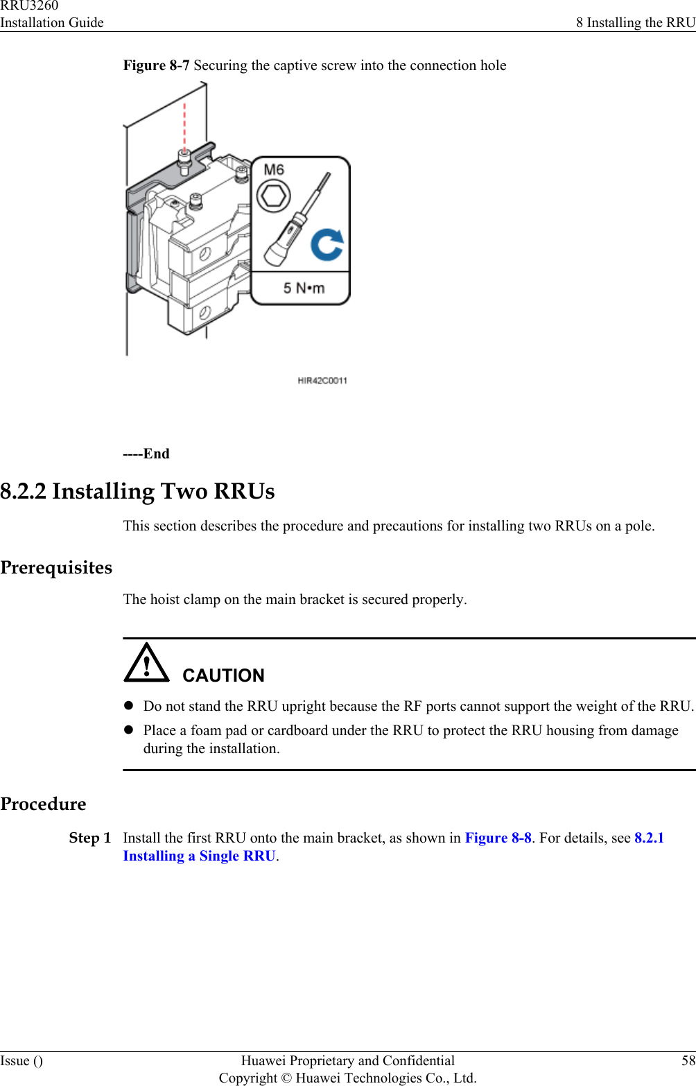
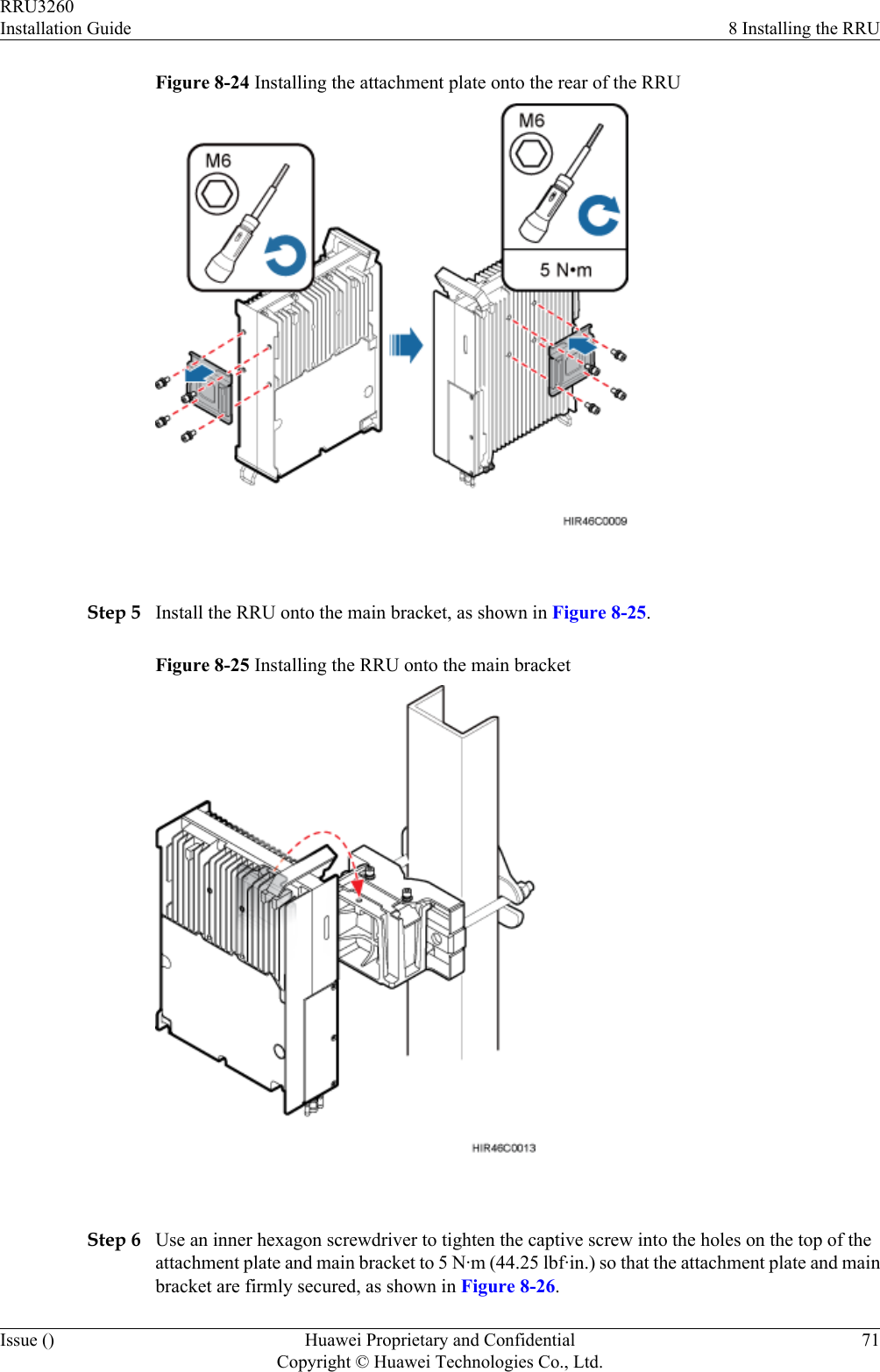
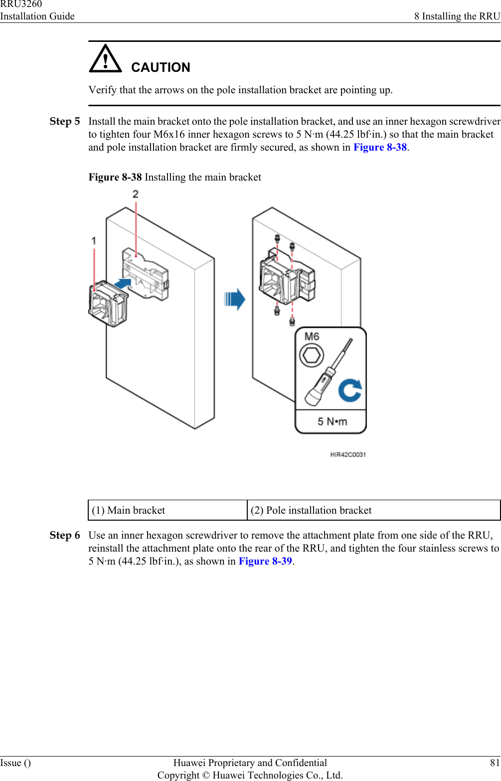
>
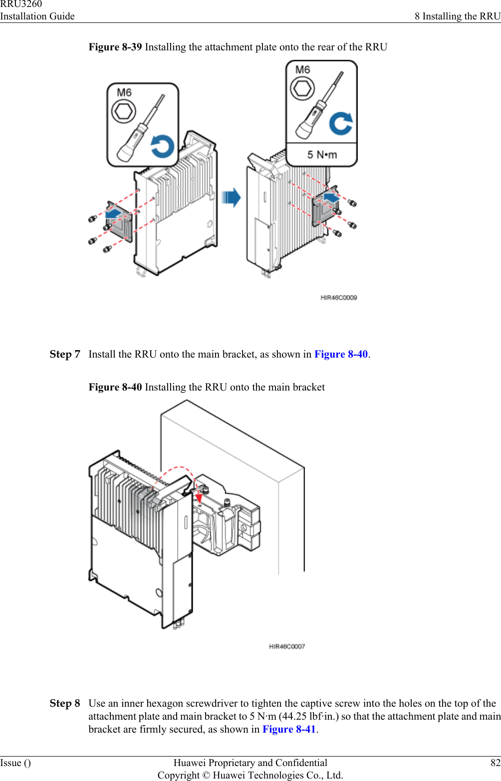
RRU3260 User Manual
Installation guide of RRU3260
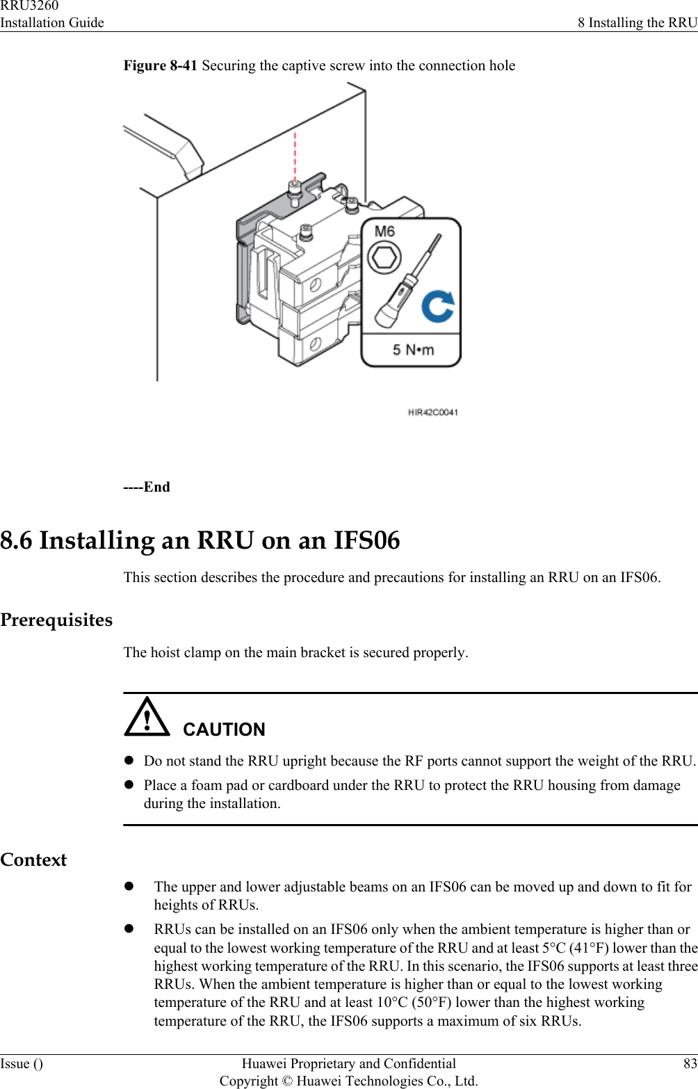
Navigation menu
Upload a User Manual
Namespaces
Wiki Guide
HTML
PDF
Info
Views
User Manual
Discussion / Help
Navigation
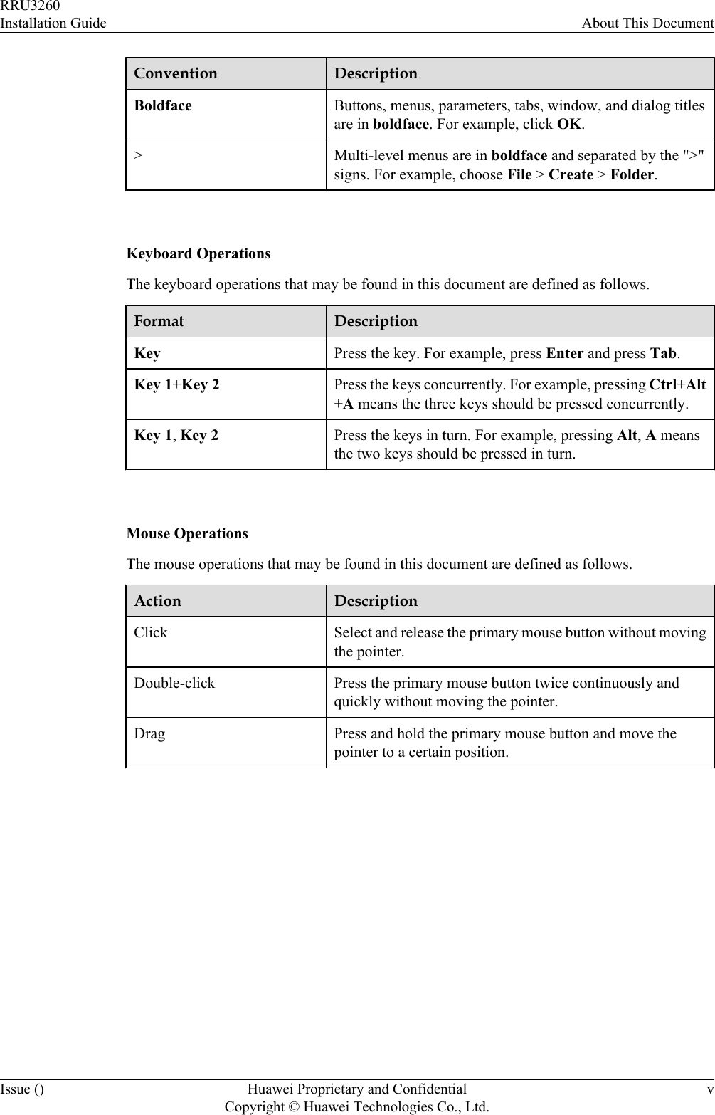
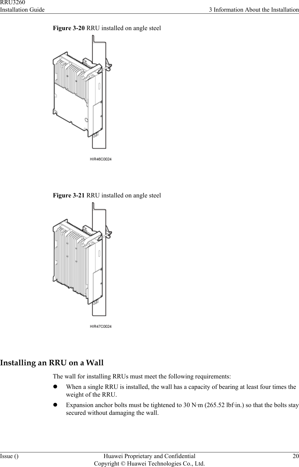
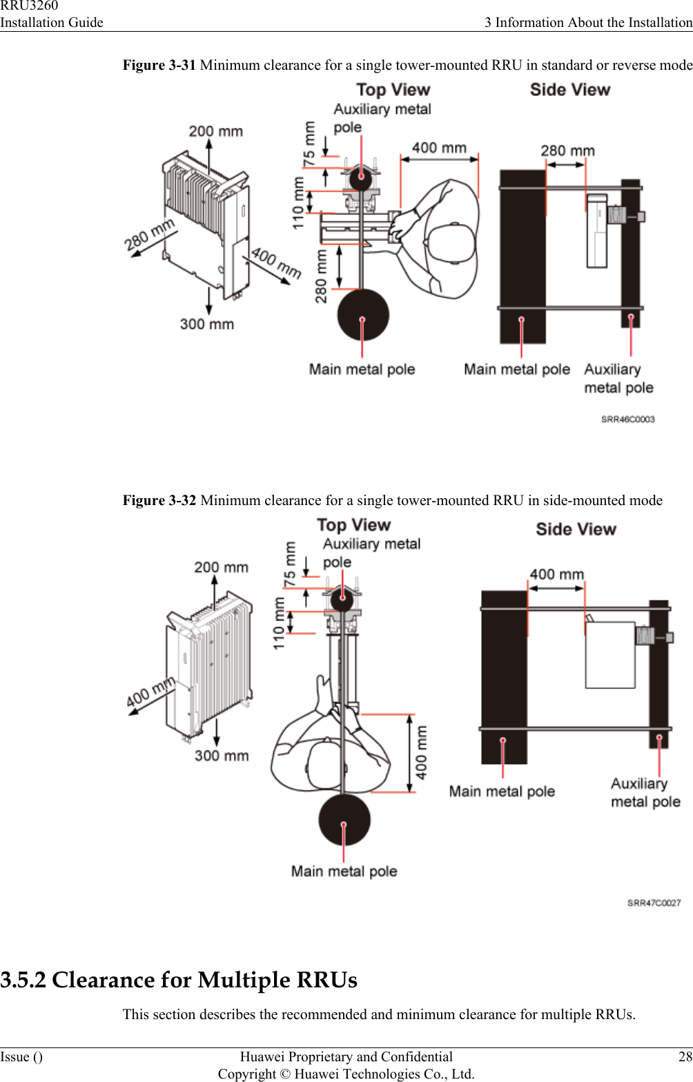
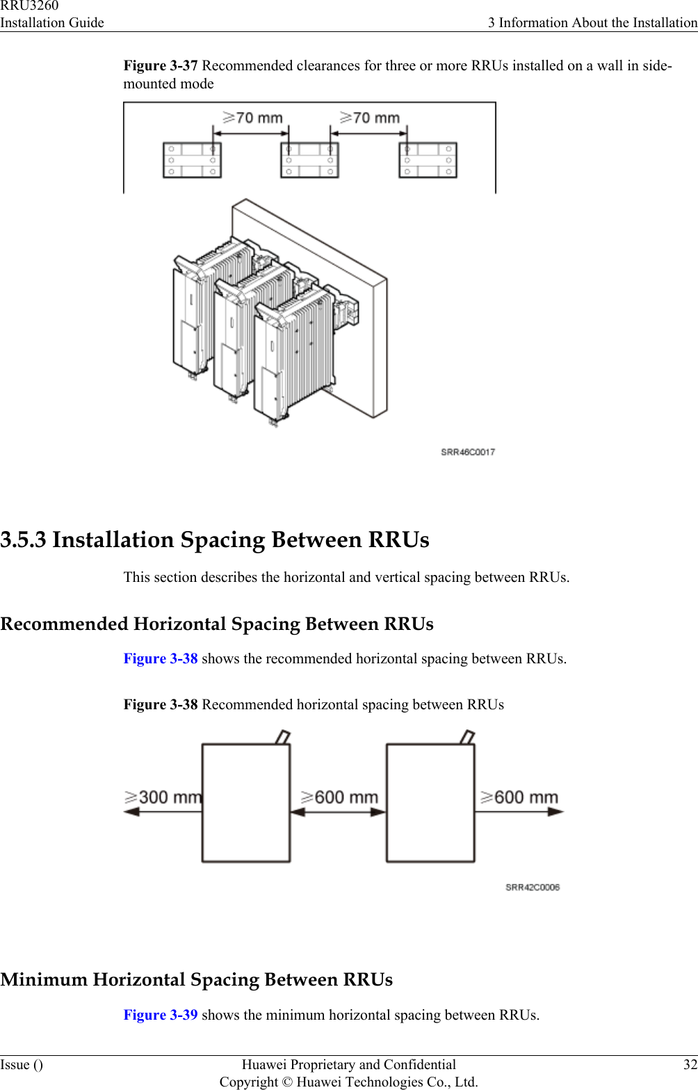
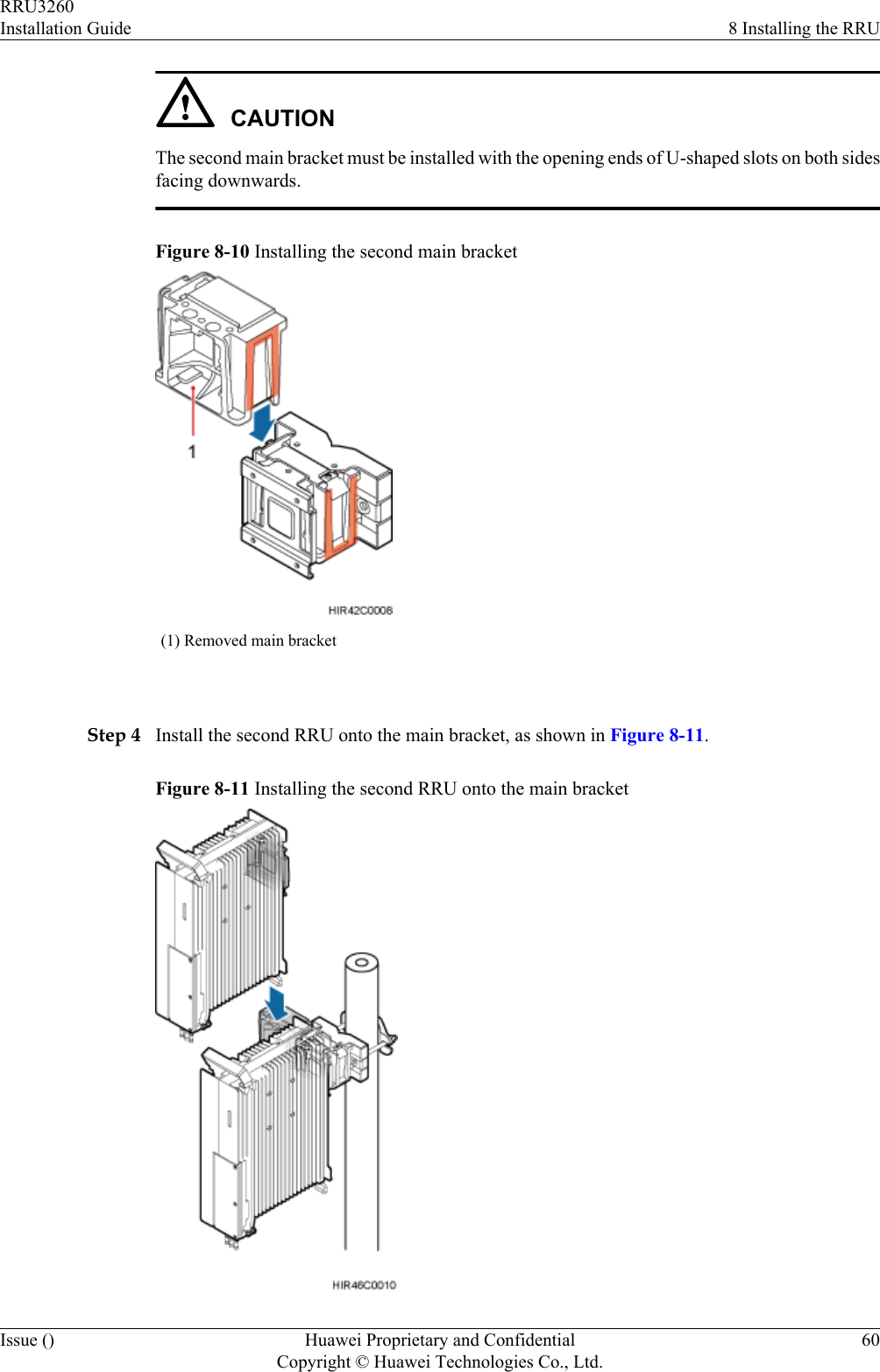
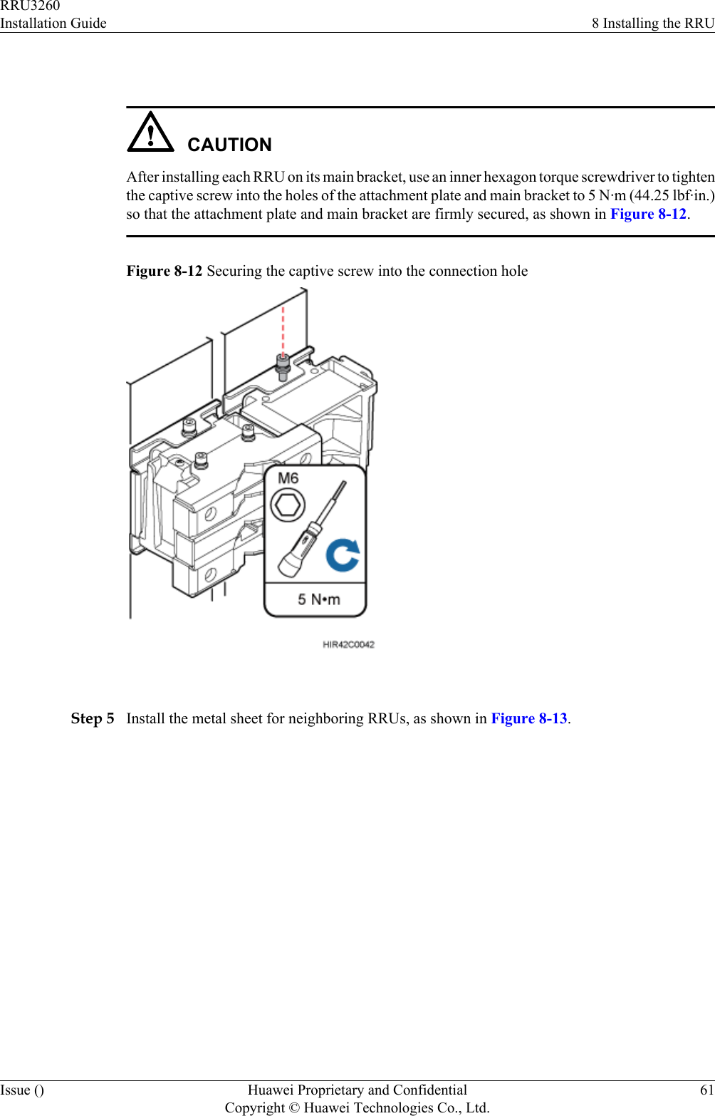
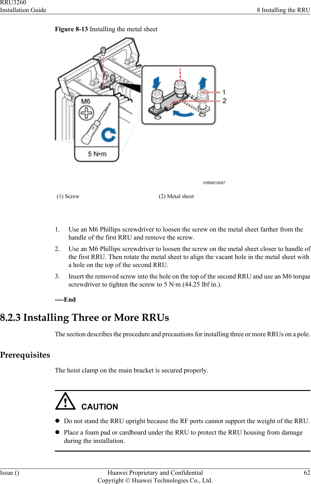
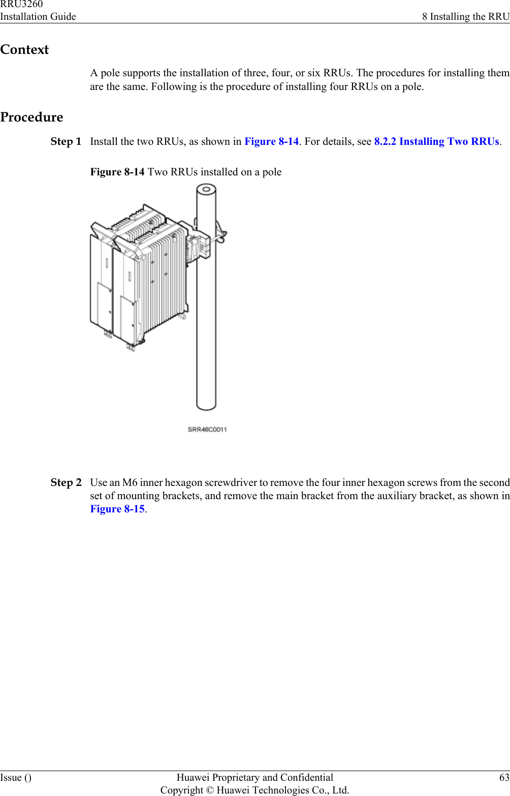
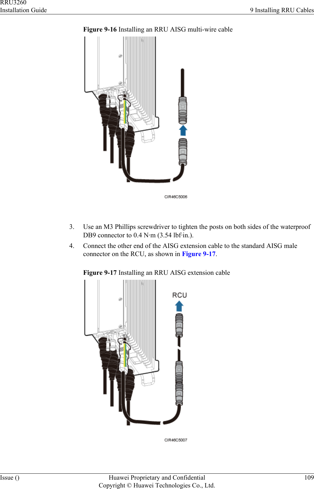
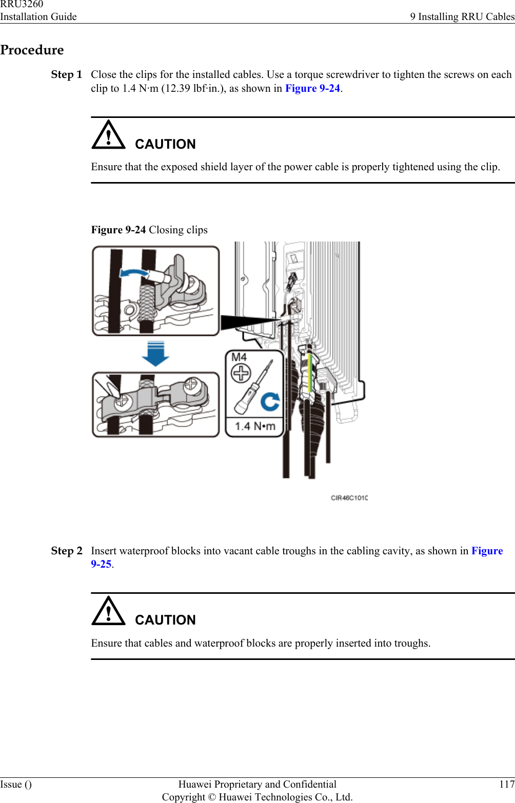
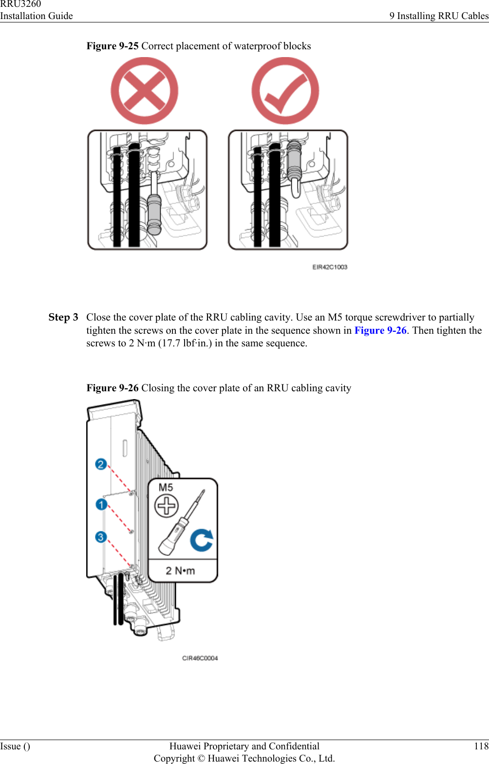
![Symbol DescriptionIndicates a tip that may help you solve a problem or savetime.Provides additional information to emphasize or supplementimportant points of the main text. General ConventionsThe general conventions that may be found in this document are defined as follows.Convention DescriptionTimes New Roman Normal paragraphs are in Times New Roman.Boldface Names of files, directories, folders, and users are inboldface. For example, log in as user root.Italic Book titles are in italics.Courier New Examples of information displayed on the screen are inCourier New. Command ConventionsThe command conventions that may be found in this document are defined as follows.Convention DescriptionBoldface The keywords of a command line are in boldface.Italic Command arguments are in italics.[ ] Items (keywords or arguments) in brackets [ ] are optional.{ x | y | ... } Optional items are grouped in braces and separated byvertical bars. One item is selected.[ x | y | ... ] Optional items are grouped in brackets and separated byvertical bars. One item is selected or no item is selected.{ x | y | ... }*Optional items are grouped in braces and separated byvertical bars. A minimum of one item or a maximum of allitems can be selected.[ x | y | ... ]*Optional items are grouped in brackets and separated byvertical bars. Several items or no item can be selected. GUI ConventionsThe GUI conventions that may be found in this document are defined as follows.RRU3260Installation Guide About This DocumentIssue () Huawei Proprietary and ConfidentialCopyright © Huawei Technologies Co., Ltd.iv](https://usermanual.wiki/Huawei-Technologies/RRU3260/User-Guide-2059459-Page-5.png)
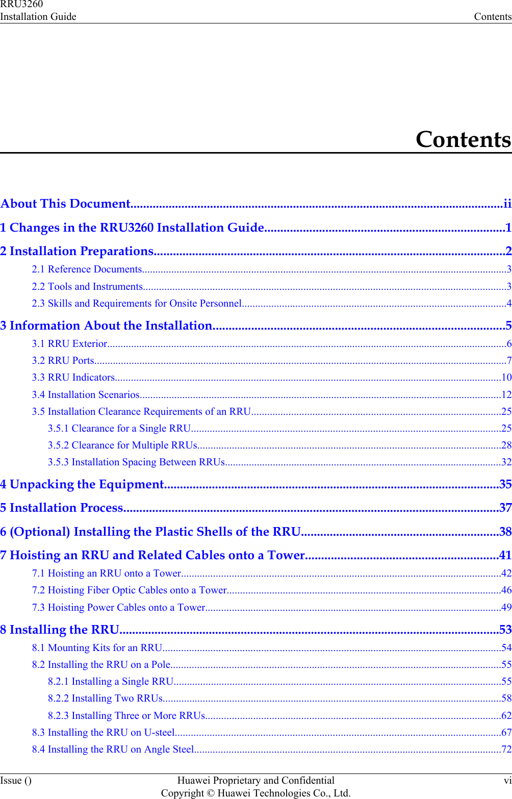
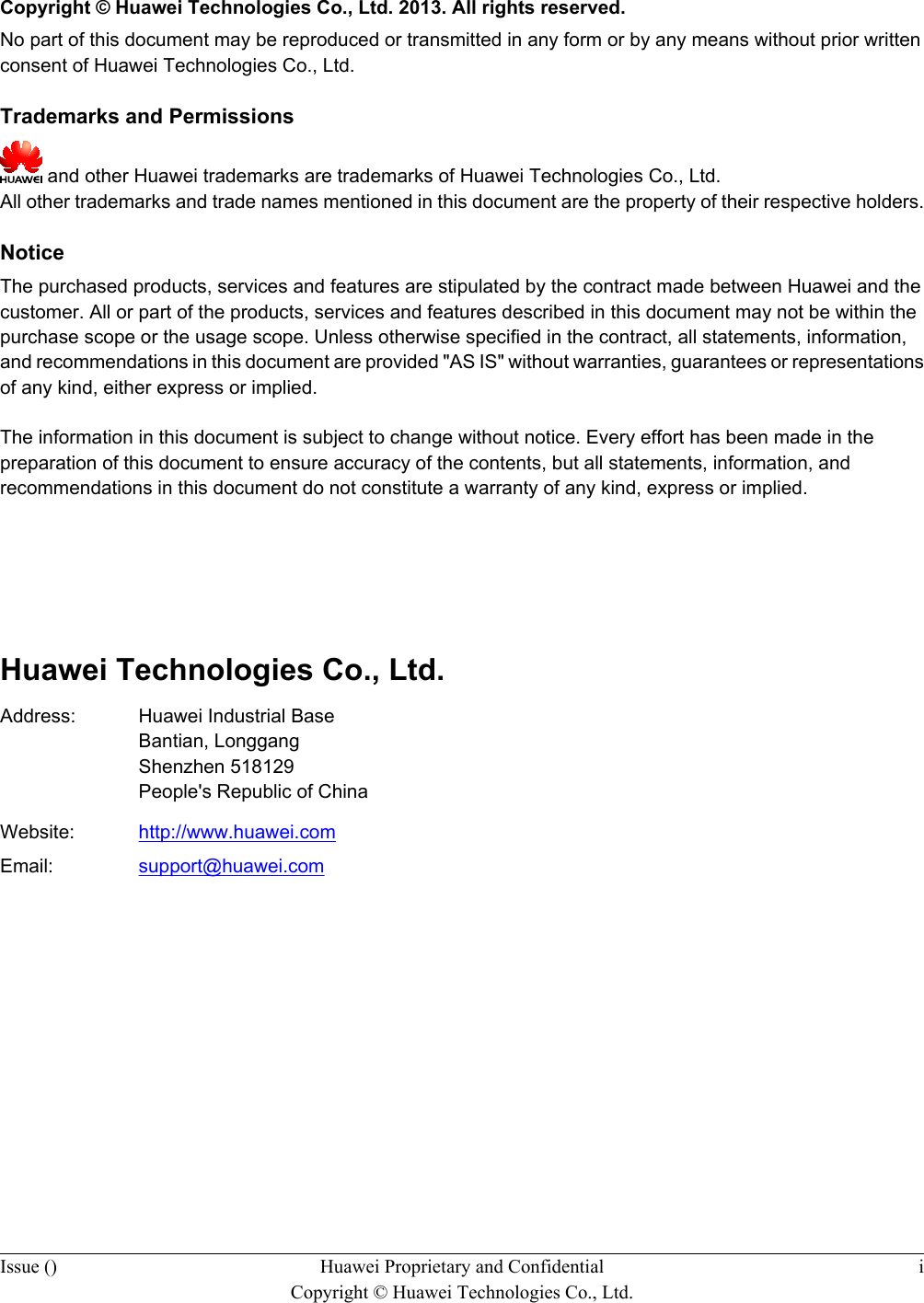
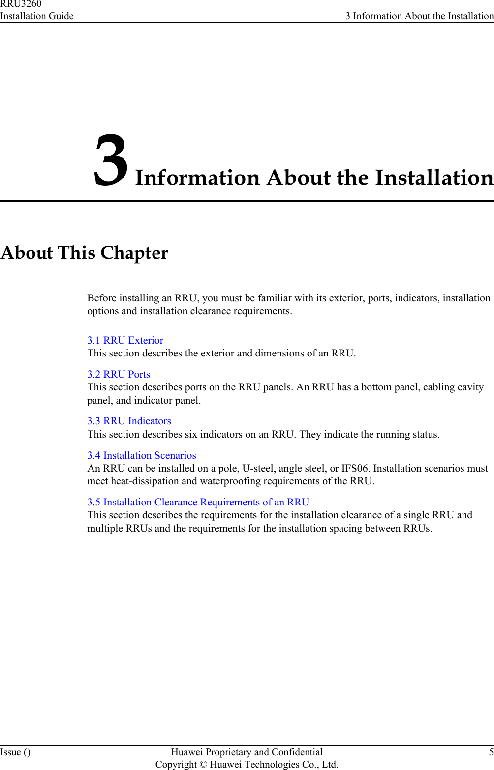
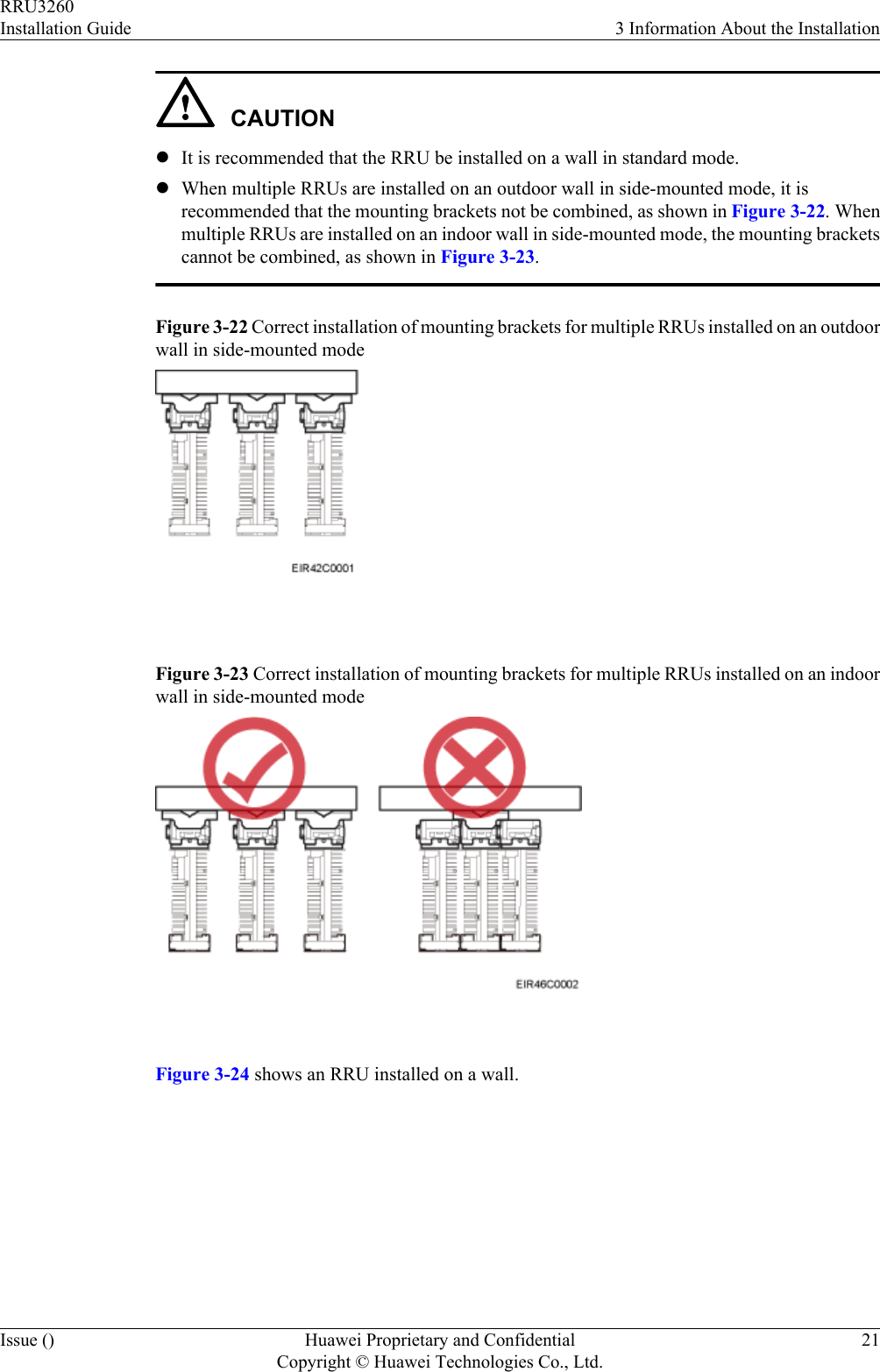
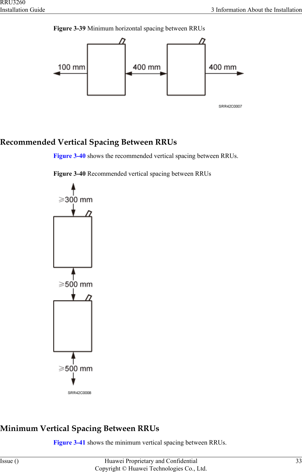
![2.1 Reference DocumentsBefore the installation, you must be familiar with reference documents.The following reference documents are required during RRU installation:lDBS3900 Installation GuidelOCB User Guide2.2 Tools and InstrumentsAll tools and instruments required for RRU installation must be ready before the installation.Hammer drill (a φ 12 bit) ESD gloves Vacuum cleanerHeat gun Phillips screwdriver (M3 toM6)Flat-head screwdriver (M3 toM6)Rubber mallet COAX crimping tool Wire stripperUtility knife Cable cutter Adjustable wrench (capacity≥ 32 mm [1.26 in.])Torque wrenchCapacity: 16 mm [0.63 in.],and 32 mm [1.26 in.]Combination wrenchCapacity: 16 mm [0.63 in.],and 32 mm [1.26 in.]RRU3260Installation Guide 2 Installation PreparationsIssue () Huawei Proprietary and ConfidentialCopyright © Huawei Technologies Co., Ltd.3](https://usermanual.wiki/Huawei-Technologies/RRU3260/User-Guide-2059459-Page-11.png)
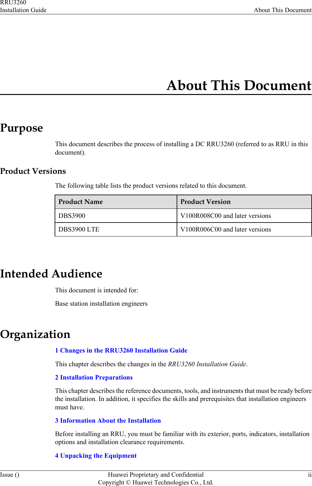
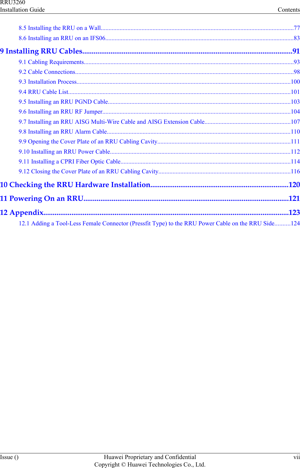
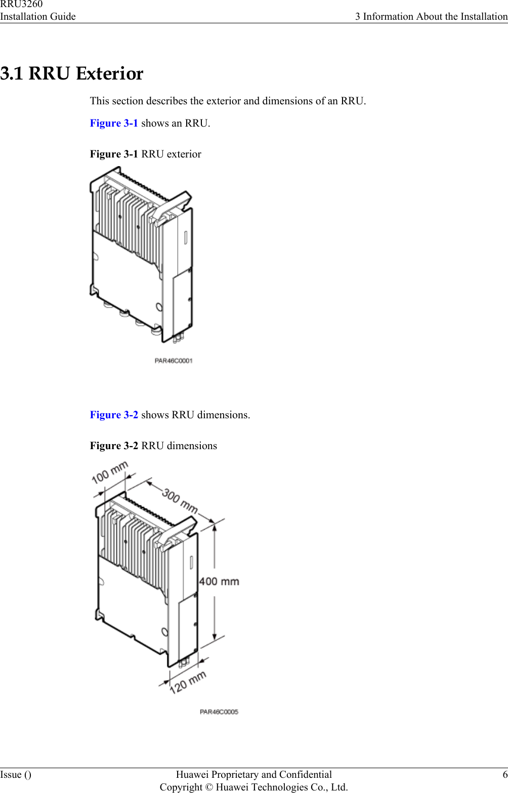
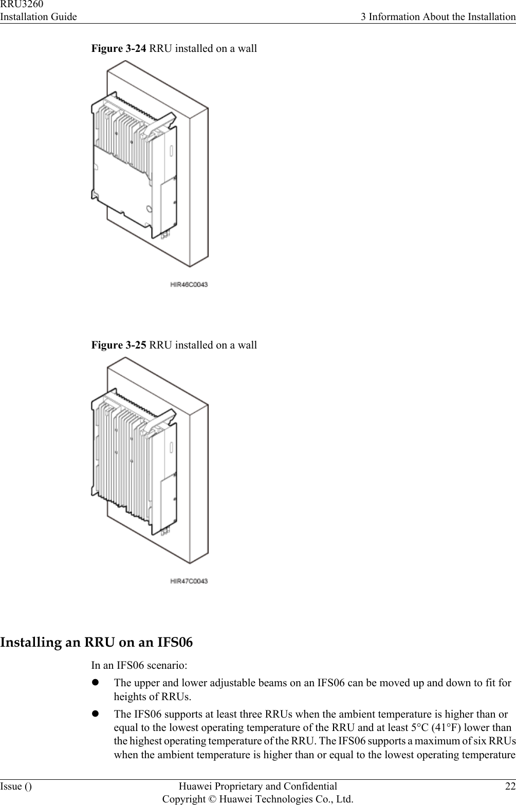
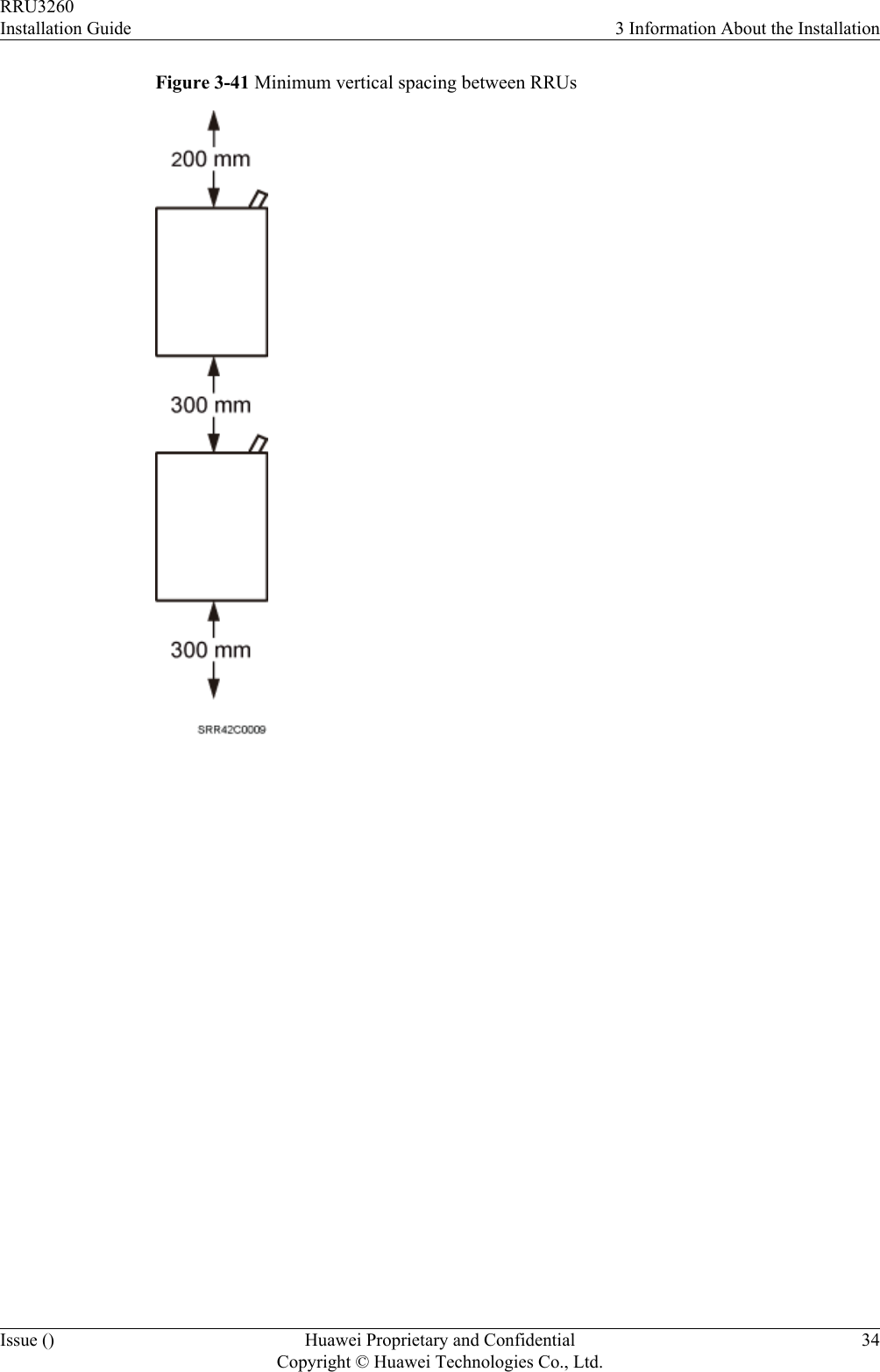
![Level Torque screwdriver5 mm (0.2 in.)5 mm (0.2 in.)(M3 to M6)(M3 to M6)Torque socketMultimeter Marker (diameter ≤ 10 mm[0.39 in.])Measuring tapeInner hexagon spanner5 mm (0.2 in.)Fixed pulley RopeHydraulic pliers - - 2.3 Skills and Requirements for Onsite PersonnelOnsite personnel must be qualified and trained. Before performing any operation, onsitepersonnel must be familiar with correct operation methods and safety precautions.Before the installation, pay attention to the following items:lThe customer's technical engineers must be trained by Huawei and be familiar with theproper installation and operation methods.lThe number of onsite personnel depends on the engineering schedule and installationenvironment. Generally, only three to five onsite personnel are necessary.RRU3260Installation Guide 2 Installation PreparationsIssue () Huawei Proprietary and ConfidentialCopyright © Huawei Technologies Co., Ltd.4](https://usermanual.wiki/Huawei-Technologies/RRU3260/User-Guide-2059459-Page-12.png)
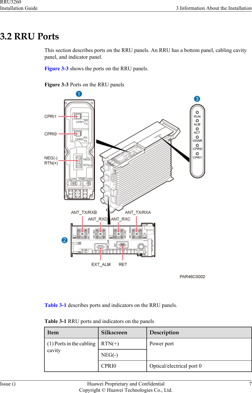
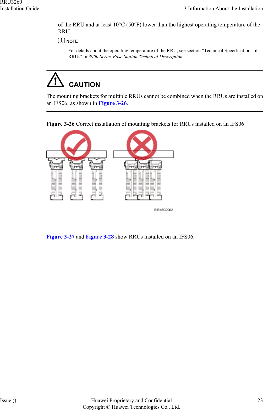
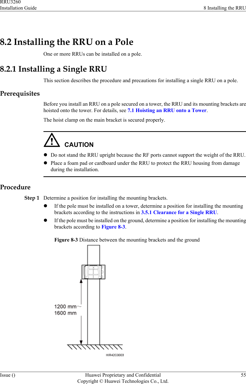
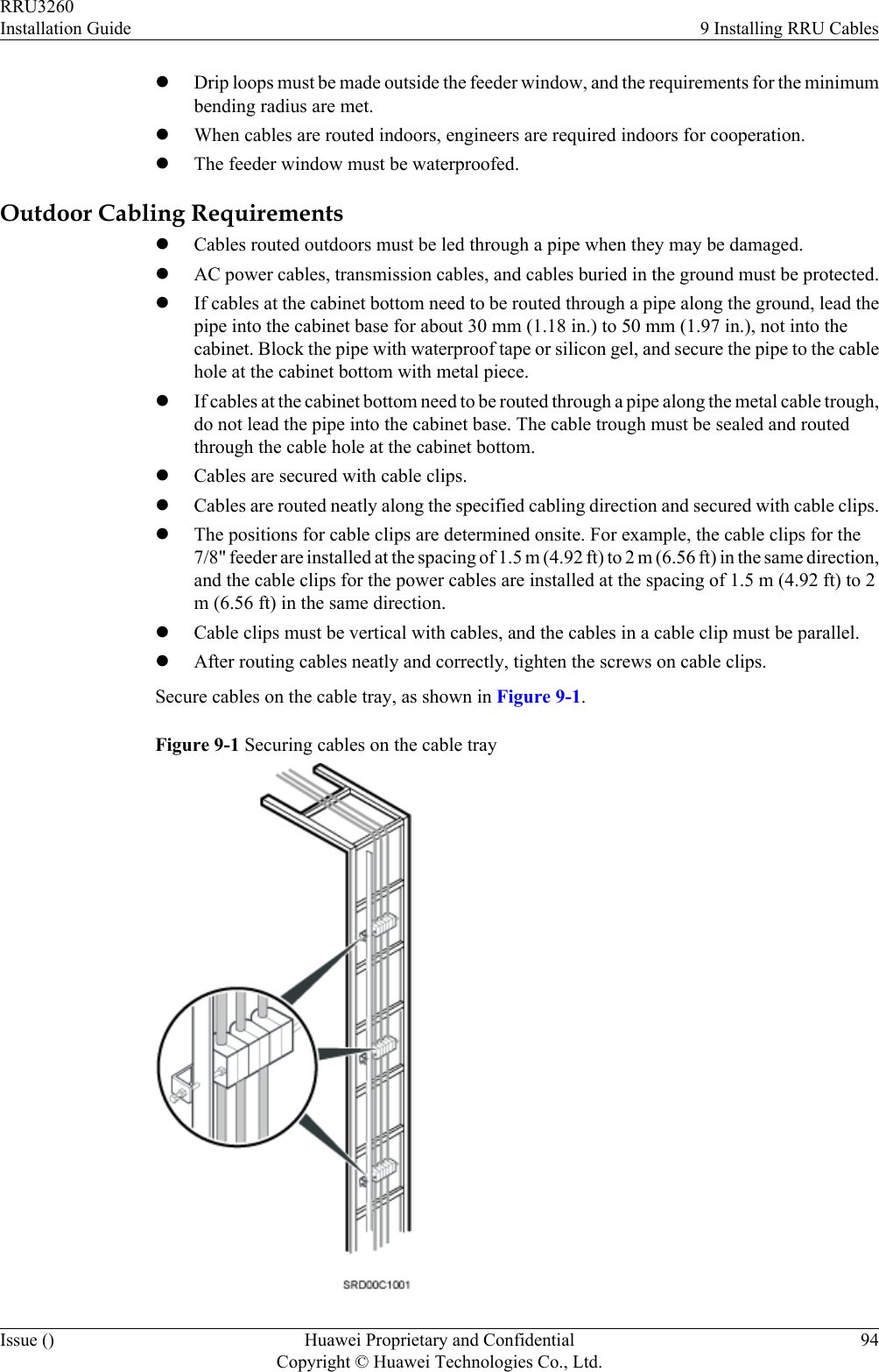
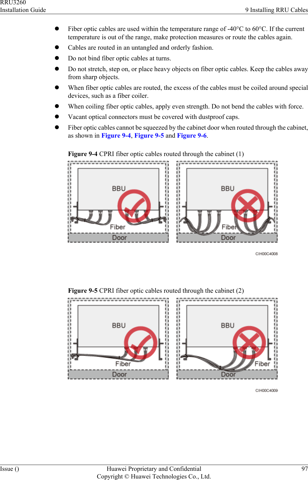
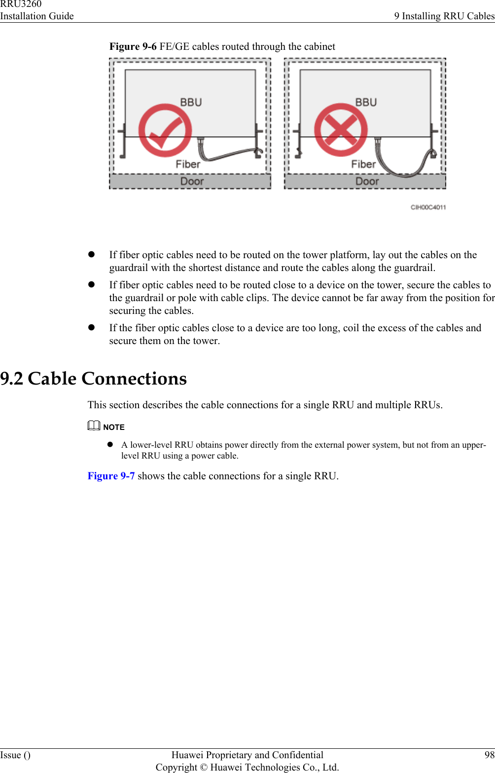
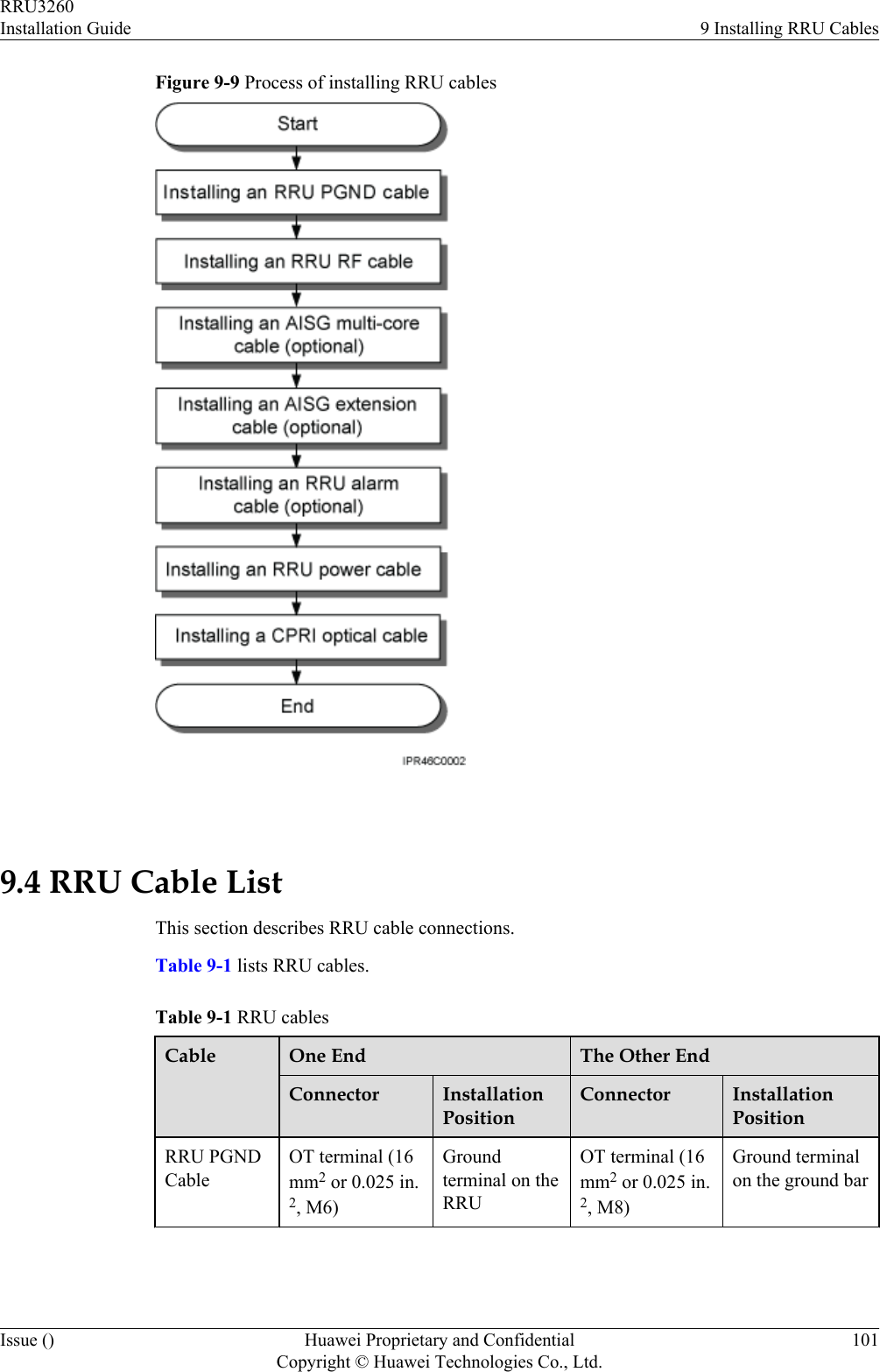
![9.1 Cabling RequirementsCables must be routed according to the specified cabling requirements to prevent signalinterference.NOTEIf a cable listed below is not required, skip the routing requirements of the cable.General Cabling RequirementsRequirements for Bending RadiuslThe bending radius of the 7/8'' feeder must be more than 250 mm (9.84 in.), and the bendingradius of the 5/4'' feeder must be more than 380 mm (14.96 in.).lThe bending radius of the 1/4'' jumper must be more than 35 mm (1.38 in.). The bendingradius of the super-flexible 1/2'' jumper must be more than 50 mm (1.97 in.), and the bendingradius of the ordinary 1/2'' jumper must be more than 127 mm (5 in.).lThe bending radius of the power cable or PGND cable must be at least three times thediameter of the cable.lThe bending radius of a fiber optic cable is at least 20 times the diameter of the fiber opticcable, and the minimum bending radius of the breakout cable at each end of the fiber opticcable is 30 mm (1.18 in.).lThe bending radius of the E1/T1 cable must be at least three times the diameter of the cable.lThe bending radius of the signal cable must be at least five times the diameter of the cable.Requirements for Cable BindinglThe same types of cable must be bound together.lDifferent types of cable must be separately routed with the minimum spacing of 30 mm(1.18 in.) and cannot be entangled.lThe cables must be bound tightly and neatly. The sheaths of the cables must not be damaged.lCable ties are installed in the same direction, and those at the same horizontal line must bein a straight line.lThe excess of indoor cable ties is trimmed off, and the excess of outdoor cable ties allowsabout 5 mm (0.2 in.), without remaining rough edges.lLabels or nameplates must be attached to both ends, joints, or turns of cables after they areinstalled.Security RequirementslCables should be placed away from sharp objects or wall burrs. If these positions areinevitable, protect the cables with protection pipes.lCables must be routed away from heat sources, or heat-insulation materials are addedbetween cables and heat sources.lSufficient slack (recommended for about 0.1 m [0.33 ft]) is provided in cables at turns orthe position close to a device, facilitating cable and device maintenance.Indoor Cabling RequirementslCables are routed indoors through the feeder window.RRU3260Installation Guide 9 Installing RRU CablesIssue () Huawei Proprietary and ConfidentialCopyright © Huawei Technologies Co., Ltd.93](https://usermanual.wiki/Huawei-Technologies/RRU3260/User-Guide-2059459-Page-101.png)

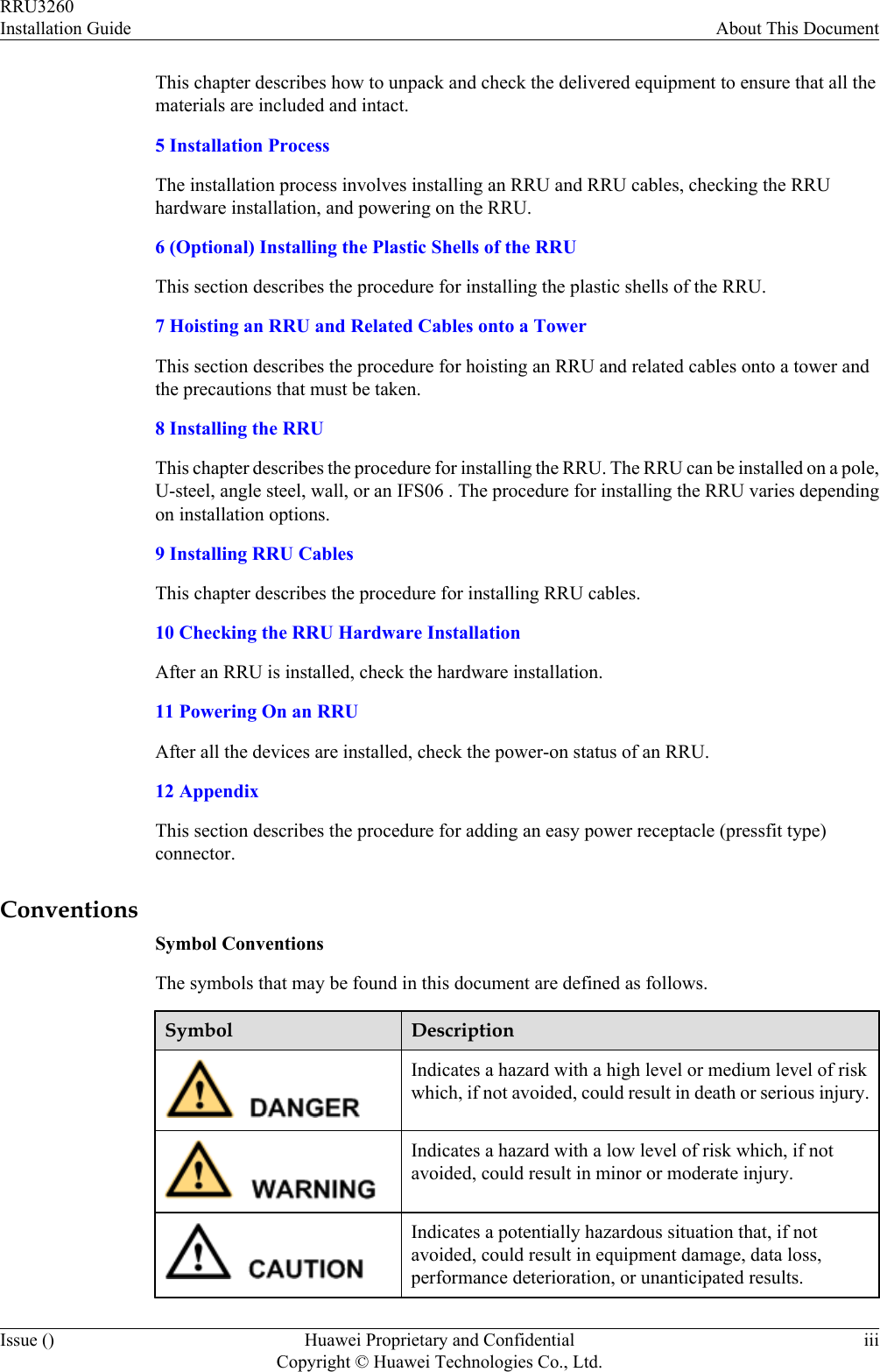
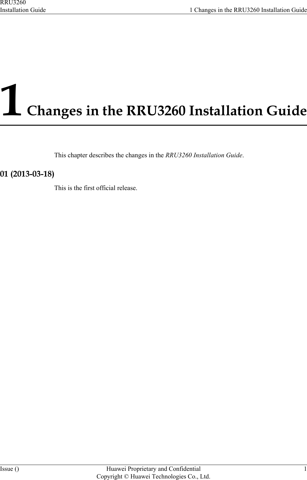
![CAUTIONEach core wire is exposed outside the tool-less female connector (pressfit type) for 1.5 mm(0.059 [in.]), as shown in Figure 12-9.Figure 12-9 Inserting core wires into the tool-less female connector (pressfit type)----EndRRU3260Installation Guide 12 AppendixIssue () Huawei Proprietary and ConfidentialCopyright © Huawei Technologies Co., Ltd.127](https://usermanual.wiki/Huawei-Technologies/RRU3260/User-Guide-2059459-Page-135.png)