Huawei Technologies RRU3260 Remote Radio Unit User Manual Installation Guide
Huawei Technologies Co.,Ltd Remote Radio Unit Installation Guide
Installation guide of RRU3260
RRU3260
Installation Guide
Issue
Date
HUAWEI TECHNOLOGIES CO., LTD.

Copyright © Huawei Technologies Co., Ltd. 2013. All rights reserved.
No part of this document may be reproduced or transmitted in any form or by any means without prior written
consent of Huawei Technologies Co., Ltd.
Trademarks and Permissions
and other Huawei trademarks are trademarks of Huawei Technologies Co., Ltd.
All other trademarks and trade names mentioned in this document are the property of their respective holders.
Notice
The purchased products, services and features are stipulated by the contract made between Huawei and the
customer. All or part of the products, services and features described in this document may not be within the
purchase scope or the usage scope. Unless otherwise specified in the contract, all statements, information,
and recommendations in this document are provided "AS IS" without warranties, guarantees or representations
of any kind, either express or implied.
The information in this document is subject to change without notice. Every effort has been made in the
preparation of this document to ensure accuracy of the contents, but all statements, information, and
recommendations in this document do not constitute a warranty of any kind, express or implied.
Huawei Technologies Co., Ltd.
Address: Huawei Industrial Base
Bantian, Longgang
Shenzhen 518129
People's Republic of China
Website: http://www.huawei.com
Email: support@huawei.com
Issue () Huawei Proprietary and Confidential
Copyright © Huawei Technologies Co., Ltd.
i
About This Document
Purpose
This document describes the process of installing a DC RRU3260 (referred to as RRU in this
document).
Product Versions
The following table lists the product versions related to this document.
Product Name Product Version
DBS3900 V100R008C00 and later versions
DBS3900 LTE V100R006C00 and later versions
Intended Audience
This document is intended for:
Base station installation engineers
Organization
1 Changes in the RRU3260 Installation Guide
This chapter describes the changes in the RRU3260 Installation Guide.
2 Installation Preparations
This chapter describes the reference documents, tools, and instruments that must be ready before
the installation. In addition, it specifies the skills and prerequisites that installation engineers
must have.
3 Information About the Installation
Before installing an RRU, you must be familiar with its exterior, ports, indicators, installation
options and installation clearance requirements.
4 Unpacking the Equipment
RRU3260
Installation Guide About This Document
Issue () Huawei Proprietary and Confidential
Copyright © Huawei Technologies Co., Ltd.
ii
This chapter describes how to unpack and check the delivered equipment to ensure that all the
materials are included and intact.
5 Installation Process
The installation process involves installing an RRU and RRU cables, checking the RRU
hardware installation, and powering on the RRU.
6 (Optional) Installing the Plastic Shells of the RRU
This section describes the procedure for installing the plastic shells of the RRU.
7 Hoisting an RRU and Related Cables onto a Tower
This section describes the procedure for hoisting an RRU and related cables onto a tower and
the precautions that must be taken.
8 Installing the RRU
This chapter describes the procedure for installing the RRU. The RRU can be installed on a pole,
U-steel, angle steel, wall, or an IFS06 . The procedure for installing the RRU varies depending
on installation options.
9 Installing RRU Cables
This chapter describes the procedure for installing RRU cables.
10 Checking the RRU Hardware Installation
After an RRU is installed, check the hardware installation.
11 Powering On an RRU
After all the devices are installed, check the power-on status of an RRU.
12 Appendix
This section describes the procedure for adding an easy power receptacle (pressfit type)
connector.
Conventions
Symbol Conventions
The symbols that may be found in this document are defined as follows.
Symbol Description
Indicates a hazard with a high level or medium level of risk
which, if not avoided, could result in death or serious injury.
Indicates a hazard with a low level of risk which, if not
avoided, could result in minor or moderate injury.
Indicates a potentially hazardous situation that, if not
avoided, could result in equipment damage, data loss,
performance deterioration, or unanticipated results.
RRU3260
Installation Guide About This Document
Issue () Huawei Proprietary and Confidential
Copyright © Huawei Technologies Co., Ltd.
iii
Symbol Description
Indicates a tip that may help you solve a problem or save
time.
Provides additional information to emphasize or supplement
important points of the main text.
General Conventions
The general conventions that may be found in this document are defined as follows.
Convention Description
Times New Roman Normal paragraphs are in Times New Roman.
Boldface Names of files, directories, folders, and users are in
boldface. For example, log in as user root.
Italic Book titles are in italics.
Courier New Examples of information displayed on the screen are in
Courier New.
Command Conventions
The command conventions that may be found in this document are defined as follows.
Convention Description
Boldface The keywords of a command line are in boldface.
Italic Command arguments are in italics.
[ ] Items (keywords or arguments) in brackets [ ] are optional.
{ x | y | ... } Optional items are grouped in braces and separated by
vertical bars. One item is selected.
[ x | y | ... ] Optional items are grouped in brackets and separated by
vertical bars. One item is selected or no item is selected.
{ x | y | ... }*Optional items are grouped in braces and separated by
vertical bars. A minimum of one item or a maximum of all
items can be selected.
[ x | y | ... ]*Optional items are grouped in brackets and separated by
vertical bars. Several items or no item can be selected.
GUI Conventions
The GUI conventions that may be found in this document are defined as follows.
RRU3260
Installation Guide About This Document
Issue () Huawei Proprietary and Confidential
Copyright © Huawei Technologies Co., Ltd.
iv
Convention Description
Boldface Buttons, menus, parameters, tabs, window, and dialog titles
are in boldface. For example, click OK.
>Multi-level menus are in boldface and separated by the ">"
signs. For example, choose File > Create > Folder.
Keyboard Operations
The keyboard operations that may be found in this document are defined as follows.
Format Description
Key Press the key. For example, press Enter and press Tab.
Key 1+Key 2 Press the keys concurrently. For example, pressing Ctrl+Alt
+A means the three keys should be pressed concurrently.
Key 1, Key 2 Press the keys in turn. For example, pressing Alt, A means
the two keys should be pressed in turn.
Mouse Operations
The mouse operations that may be found in this document are defined as follows.
Action Description
Click Select and release the primary mouse button without moving
the pointer.
Double-click Press the primary mouse button twice continuously and
quickly without moving the pointer.
Drag Press and hold the primary mouse button and move the
pointer to a certain position.
RRU3260
Installation Guide About This Document
Issue () Huawei Proprietary and Confidential
Copyright © Huawei Technologies Co., Ltd.
v

Contents
About This Document.....................................................................................................................ii
1 Changes in the RRU3260 Installation Guide...........................................................................1
2 Installation Preparations..............................................................................................................2
2.1 Reference Documents.........................................................................................................................................3
2.2 Tools and Instruments........................................................................................................................................3
2.3 Skills and Requirements for Onsite Personnel...................................................................................................4
3 Information About the Installation...........................................................................................5
3.1 RRU Exterior......................................................................................................................................................6
3.2 RRU Ports...........................................................................................................................................................7
3.3 RRU Indicators.................................................................................................................................................10
3.4 Installation Scenarios........................................................................................................................................12
3.5 Installation Clearance Requirements of an RRU..............................................................................................25
3.5.1 Clearance for a Single RRU....................................................................................................................25
3.5.2 Clearance for Multiple RRUs..................................................................................................................28
3.5.3 Installation Spacing Between RRUs........................................................................................................32
4 Unpacking the Equipment.........................................................................................................35
5 Installation Process.....................................................................................................................37
6 (Optional) Installing the Plastic Shells of the RRU..............................................................38
7 Hoisting an RRU and Related Cables onto a Tower............................................................41
7.1 Hoisting an RRU onto a Tower........................................................................................................................42
7.2 Hoisting Fiber Optic Cables onto a Tower.......................................................................................................46
7.3 Hoisting Power Cables onto a Tower...............................................................................................................49
8 Installing the RRU.......................................................................................................................53
8.1 Mounting Kits for an RRU...............................................................................................................................54
8.2 Installing the RRU on a Pole............................................................................................................................55
8.2.1 Installing a Single RRU...........................................................................................................................55
8.2.2 Installing Two RRUs...............................................................................................................................58
8.2.3 Installing Three or More RRUs...............................................................................................................62
8.3 Installing the RRU on U-steel..........................................................................................................................67
8.4 Installing the RRU on Angle Steel...................................................................................................................72
RRU3260
Installation Guide Contents
Issue () Huawei Proprietary and Confidential
Copyright © Huawei Technologies Co., Ltd.
vi

8.5 Installing the RRU on a Wall...........................................................................................................................77
8.6 Installing an RRU on an IFS06.........................................................................................................................83
9 Installing RRU Cables................................................................................................................91
9.1 Cabling Requirements......................................................................................................................................93
9.2 Cable Connections............................................................................................................................................98
9.3 Installation Process.........................................................................................................................................100
9.4 RRU Cable List..............................................................................................................................................101
9.5 Installing an RRU PGND Cable.....................................................................................................................103
9.6 Installing an RRU RF Jumper........................................................................................................................104
9.7 Installing an RRU AISG Multi-Wire Cable and AISG Extension Cable.......................................................107
9.8 Installing an RRU Alarm Cable......................................................................................................................110
9.9 Opening the Cover Plate of an RRU Cabling Cavity.....................................................................................111
9.10 Installing an RRU Power Cable....................................................................................................................112
9.11 Installing a CPRI Fiber Optic Cable.............................................................................................................114
9.12 Closing the Cover Plate of an RRU Cabling Cavity....................................................................................116
10 Checking the RRU Hardware Installation..........................................................................120
11 Powering On an RRU.............................................................................................................121
12 Appendix...................................................................................................................................123
12.1 Adding a Tool-Less Female Connector (Pressfit Type) to the RRU Power Cable on the RRU Side..........124
RRU3260
Installation Guide Contents
Issue () Huawei Proprietary and Confidential
Copyright © Huawei Technologies Co., Ltd.
vii

1 Changes in the RRU3260 Installation Guide
This chapter describes the changes in the RRU3260 Installation Guide.
01 (2013-03-18)
This is the first official release.
RRU3260
Installation Guide 1 Changes in the RRU3260 Installation Guide
Issue () Huawei Proprietary and Confidential
Copyright © Huawei Technologies Co., Ltd.
1

2 Installation Preparations
About This Chapter
This chapter describes the reference documents, tools, and instruments that must be ready before
the installation. In addition, it specifies the skills and prerequisites that installation engineers
must have.
2.1 Reference Documents
Before the installation, you must be familiar with reference documents.
2.2 Tools and Instruments
All tools and instruments required for RRU installation must be ready before the installation.
2.3 Skills and Requirements for Onsite Personnel
Onsite personnel must be qualified and trained. Before performing any operation, onsite
personnel must be familiar with correct operation methods and safety precautions.
RRU3260
Installation Guide 2 Installation Preparations
Issue () Huawei Proprietary and Confidential
Copyright © Huawei Technologies Co., Ltd.
2
2.1 Reference Documents
Before the installation, you must be familiar with reference documents.
The following reference documents are required during RRU installation:
lDBS3900 Installation Guide
lOCB User Guide
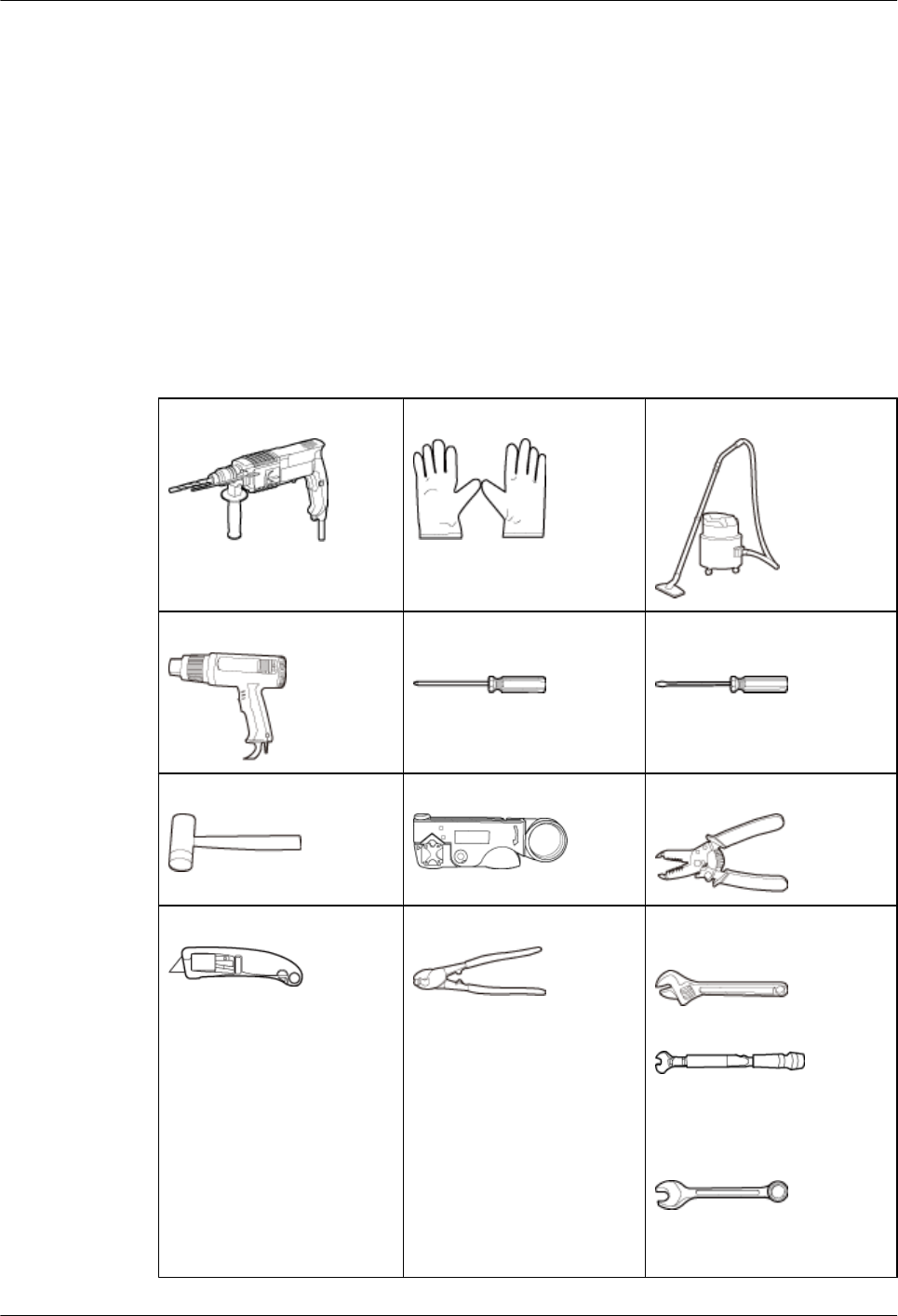
2.2 Tools and Instruments
All tools and instruments required for RRU installation must be ready before the installation.
Hammer drill (a φ 12 bit) ESD gloves Vacuum cleaner
Heat gun Phillips screwdriver (M3 to
M6)
Flat-head screwdriver (M3 to
M6)
Rubber mallet COAX crimping tool Wire stripper
Utility knife Cable cutter Adjustable wrench (capacity
≥ 32 mm [1.26 in.])
Torque wrench
Capacity: 16 mm [0.63 in.],
and 32 mm [1.26 in.]
Combination wrench
Capacity: 16 mm [0.63 in.],
and 32 mm [1.26 in.]
RRU3260
Installation Guide 2 Installation Preparations
Issue () Huawei Proprietary and Confidential
Copyright © Huawei Technologies Co., Ltd.
3
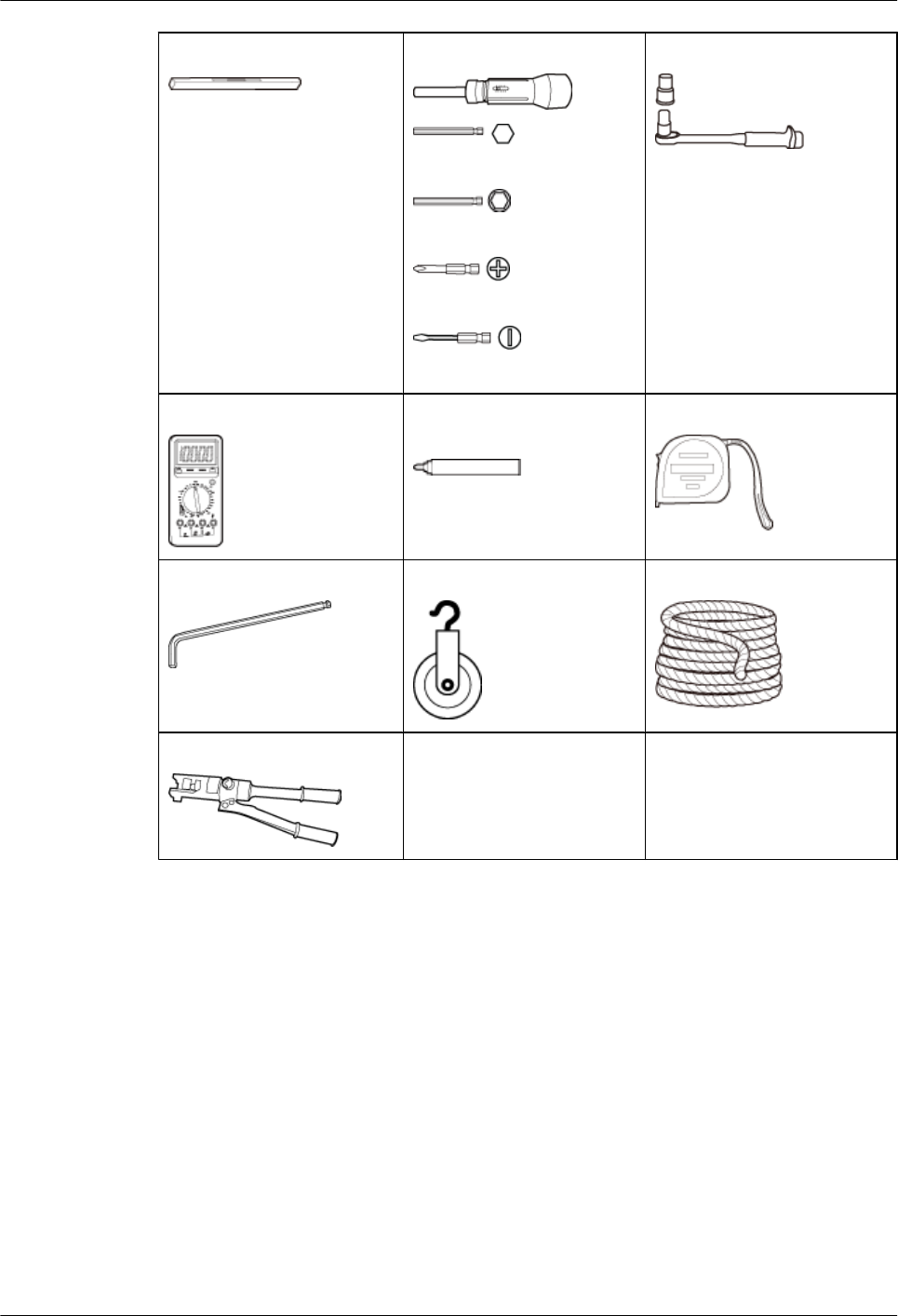
Level Torque screwdriver
5 mm (0.2 in.)
5 mm (0.2 in.)
(M3 to M6)
(M3 to M6)
Torque socket
Multimeter Marker (diameter ≤ 10 mm
[0.39 in.])
Measuring tape
Inner hexagon spanner
5 mm (0.2 in.)
Fixed pulley Rope
Hydraulic pliers - -
2.3 Skills and Requirements for Onsite Personnel
Onsite personnel must be qualified and trained. Before performing any operation, onsite
personnel must be familiar with correct operation methods and safety precautions.
Before the installation, pay attention to the following items:
lThe customer's technical engineers must be trained by Huawei and be familiar with the
proper installation and operation methods.
lThe number of onsite personnel depends on the engineering schedule and installation
environment. Generally, only three to five onsite personnel are necessary.
RRU3260
Installation Guide 2 Installation Preparations
Issue () Huawei Proprietary and Confidential
Copyright © Huawei Technologies Co., Ltd.
4

3 Information About the Installation
About This Chapter
Before installing an RRU, you must be familiar with its exterior, ports, indicators, installation
options and installation clearance requirements.
3.1 RRU Exterior
This section describes the exterior and dimensions of an RRU.
3.2 RRU Ports
This section describes ports on the RRU panels. An RRU has a bottom panel, cabling cavity
panel, and indicator panel.
3.3 RRU Indicators
This section describes six indicators on an RRU. They indicate the running status.
3.4 Installation Scenarios
An RRU can be installed on a pole, U-steel, angle steel, or IFS06. Installation scenarios must
meet heat-dissipation and waterproofing requirements of the RRU.
3.5 Installation Clearance Requirements of an RRU
This section describes the requirements for the installation clearance of a single RRU and
multiple RRUs and the requirements for the installation spacing between RRUs.
RRU3260
Installation Guide 3 Information About the Installation
Issue () Huawei Proprietary and Confidential
Copyright © Huawei Technologies Co., Ltd.
5
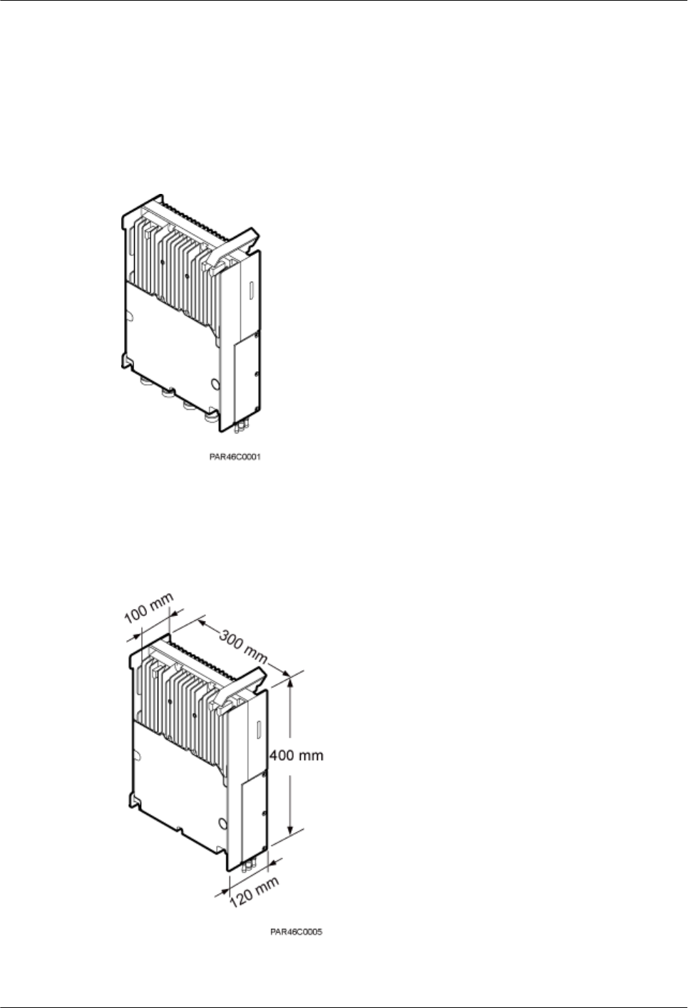
3.1 RRU Exterior
This section describes the exterior and dimensions of an RRU.
Figure 3-1 shows an RRU.
Figure 3-1 RRU exterior
Figure 3-2 shows RRU dimensions.
Figure 3-2 RRU dimensions
RRU3260
Installation Guide 3 Information About the Installation
Issue () Huawei Proprietary and Confidential
Copyright © Huawei Technologies Co., Ltd.
6
3.2 RRU Ports
This section describes ports on the RRU panels. An RRU has a bottom panel, cabling cavity
panel, and indicator panel.
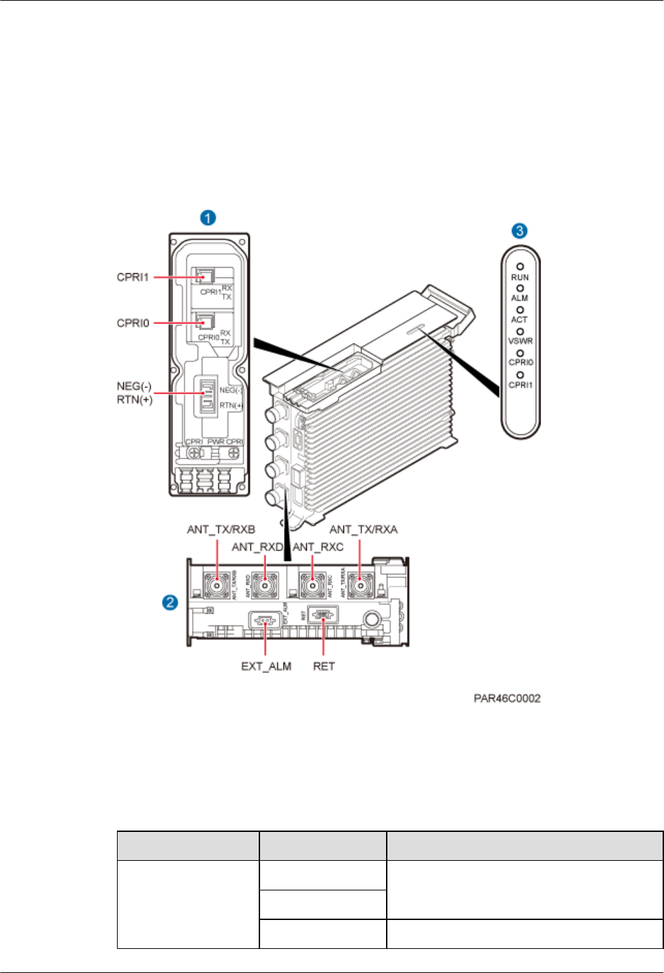
Figure 3-3 shows the ports on the RRU panels.
Figure 3-3 Ports on the RRU panels
Table 3-1 describes ports and indicators on the RRU panels.
Table 3-1 RRU ports and indicators on the panels
Item Silkscreen Description
(1) Ports in the cabling
cavity
RTN(+) Power port
NEG(-)
CPRI0 Optical/electrical port 0
RRU3260
Installation Guide 3 Information About the Installation
Issue () Huawei Proprietary and Confidential
Copyright © Huawei Technologies Co., Ltd.
7
Item Silkscreen Description
CPRI1 Optical/electrical port 1
(2) Ports at the bottom ANT_TX/RXA TX/RX port A, supporting RET signal
transmission
ANT_RXC RX port C
ANT_RXD RX port D
ANT_TX/RXB TX/RX port B
EXT_ALM Alarm port
RET Communication port for the RET antenna,
supporting RET signal transmission
(3) Indicators RUN For details, see 3.3 RRU Indicators.
ALM
ACT
VSWR
CPRI0
CPRI1
Table 3-2 describes how to use RF ports.
Table 3-2 Usage of RF ports
Product Version TX/RX
Channe
l
Number
of Used
RF Ports
Usage Remarks
lDBS3900
V100R004C00
lDBS3900
WCDMA
V200R013C00
1x2T2R 2 ANT_TX/RXA and
ANT_TX/RXB are used
together.
A single
sector
lDBS3900
V100R007C00
and later versions
lDBS3900
WCDMA
V200R014C00
and later versions
1x1T2R 2 Recommended: ANT_TX/
RXA and ANT_RXC are
used together.
Optional: ANT_TX/RXB
and ANT_RXD are used
together.
A single
sector
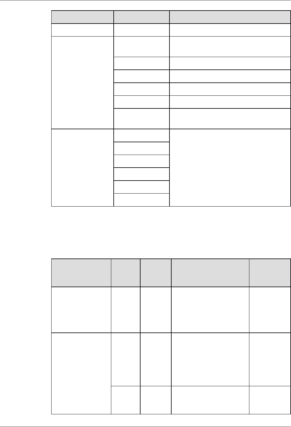
1x2T2R 2 ANT_TX/RXA and
ANT_TX/RXB are used
together.
A single
sector
RRU3260
Installation Guide 3 Information About the Installation
Issue () Huawei Proprietary and Confidential
Copyright © Huawei Technologies Co., Ltd.
8
Product Version TX/RX
Channe
l
Number
of Used
RF Ports
Usage Remarks
1x2T4R 4 ANT_TX/RXA, ANT_TX/
RXB, ANT_RXC, and
ANT_RXD are used
together for one sector, with
ANT_TX/RXA and
ANT_RXC combined and
ANT_TX/RXB and
ANT_RXD combined.
A single
sector
2x1T2R 4 ANT_TX/RXA and
ANT_RXC are used for one
sector; ANT_TX/RXB and
ANT_RXD are used for the
other sector.
Two sectors
Figure 3-5 shows the recommended usage of RF ports on an RRU used for DBS3900
V100R004C00, or DBS3900 WCDMA V200R013C00.
Figure 3-4 Recommended usage of RF ports on an RRU used for DBS3900 V100R004C00, or
DBS3900 WCDMA V200R013C00
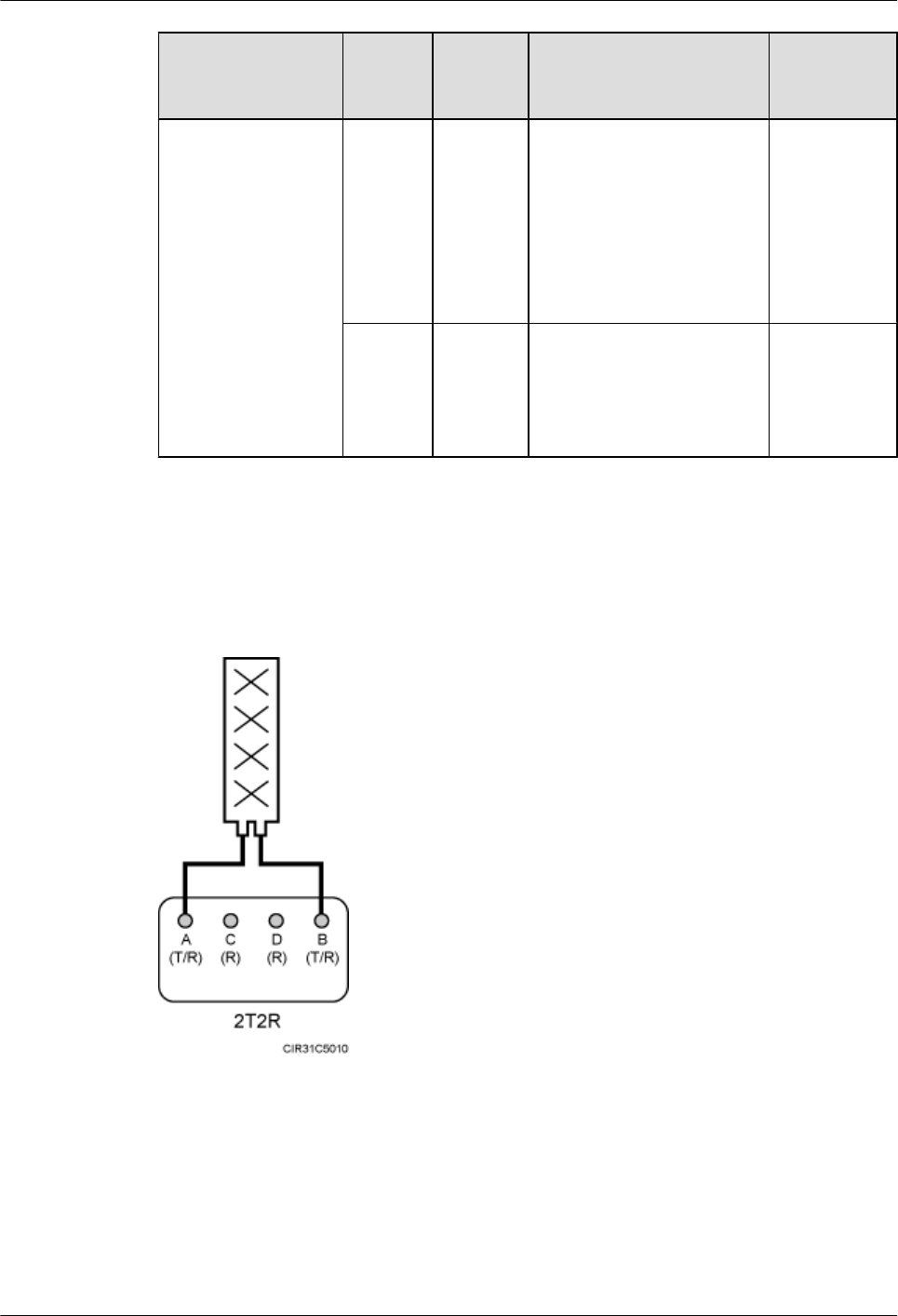
Figure 3-5 shows the recommended usage of RF ports on an RRU used for DBS3900
V100R007C00 and later versions, or DBS3900 WCDMA V200R014C00 and later versions.
RRU3260
Installation Guide 3 Information About the Installation
Issue () Huawei Proprietary and Confidential
Copyright © Huawei Technologies Co., Ltd.
9
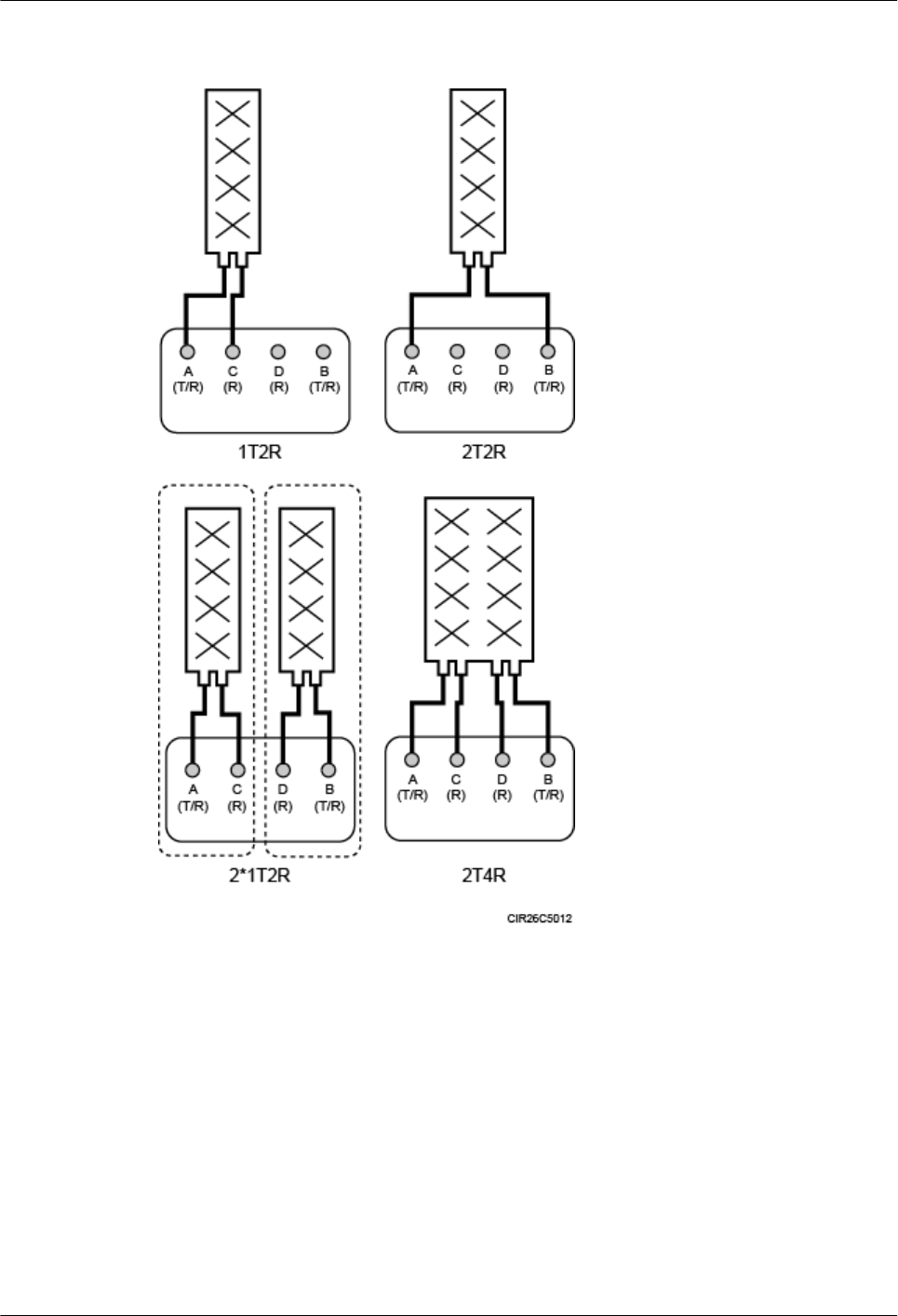
Figure 3-5 Recommended usage of RF ports on an RRU used for DBS3900 V100R007C00 and
later versions, or DBS3900 WCDMA V200R014C00 and later versions
3.3 RRU Indicators
This section describes six indicators on an RRU. They indicate the running status.
For detailed positions of RRU indicators, see 3.2 RRU Ports.
Table 3-3 describes RRU indicators.
RRU3260
Installation Guide 3 Information About the Installation
Issue () Huawei Proprietary and Confidential
Copyright © Huawei Technologies Co., Ltd.
10

Table 3-3 RRU indicators
Indicator Color Status Meaning
RUN Green Steady on There is power supply, but the module is
faulty.
Steady off There is no power supply, or the module is
faulty.
Blinking (on for
1s and off for 1s)
The board is functioning properly.
Blinking (on for
0.125s and off for
0.125s)
Software is being loaded to the module, or
the module is not started.
ALM Red Steady on Alarms are generated, and the module must
be replaced.
Blinking (on for
1s and off for 1s)
Alarms are generated. The alarms may be
caused by the faults on the related boards or
ports. Therefore, you need to locate the fault
before deciding whether to replace the
module.
Steady off No alarm is generated.
ACT Green Steady on The module is running properly with TX
channels enabled or the software is being
loaded without RRU running.
Blinking (on for
1s and off for 1s)
The module is running properly with TX
channels disabled.
VSWR Red Steady off No Voltage Standing Wave Ratio (VSWR)
alarm is generated.
Blinking (on for
1s and off for 1s)
VSWR alarms are generated on the
ANT_TX/RXB port.
Steady on VSWR alarms are generated on the
ANT_TX/RXA port.
Blinking (on for
0.125s and off for
0.125s)
VSWR alarms are generated on the
ANT_TX/RXA and ANT_TX/RXB ports.
CPRI0 Red or
green
Steady green The CPRI link is functioning properly.
Steady red An optical module fails to transmit or receive
signals because the optical module is faulty
or the fiber optic cable is broken.
Blinking red (on
for 1s and off for
1s)
The CPRI link is out of lock because of a
failure in clock lock between two modes or
mismatched data rates over CPRI ports.
RRU3260
Installation Guide 3 Information About the Installation
Issue () Huawei Proprietary and Confidential
Copyright © Huawei Technologies Co., Ltd.
11
Indicator Color Status Meaning
Steady off The optical module cannot be detected, or the
optical module is powered off.
CPRI1 Red or
green
Steady green The CPRI link is functioning properly.
Steady red An optical module fails to transmit or receive
signals because the optical module is faulty
or the fiber optic cable is broken.
Blinking red (on
for 1s and off for
1s)
The CPRI link is out of lock because of a
failure in clock lock between two modes or
mismatched data rates over CPRI ports.
Steady off The optical module cannot be detected, or the
optical module is powered off.
3.4 Installation Scenarios
An RRU can be installed on a pole, U-steel, angle steel, or IFS06. Installation scenarios must
meet heat-dissipation and waterproofing requirements of the RRU.
Requirements for the Installation Scenarios
Application scenarios:
To ensure proper heat dissipation of the RRU, the following requirements must be met:
lThe RRU cannot be installed in an enclosed cabinet without a cooling system.
lThe RRU cannot be installed in an enclosed camouflage box.
lThe RRU cannot be installed in an enclosed equipment room without a cooling system.
lWhen multiple RRUs are installed in centralized mode, the minimum clearance
requirements must be met. For details about the minimum clearance requirements, see 3.5.2
Clearance for Multiple RRUs and 3.5.3 Installation Spacing Between RRUs.
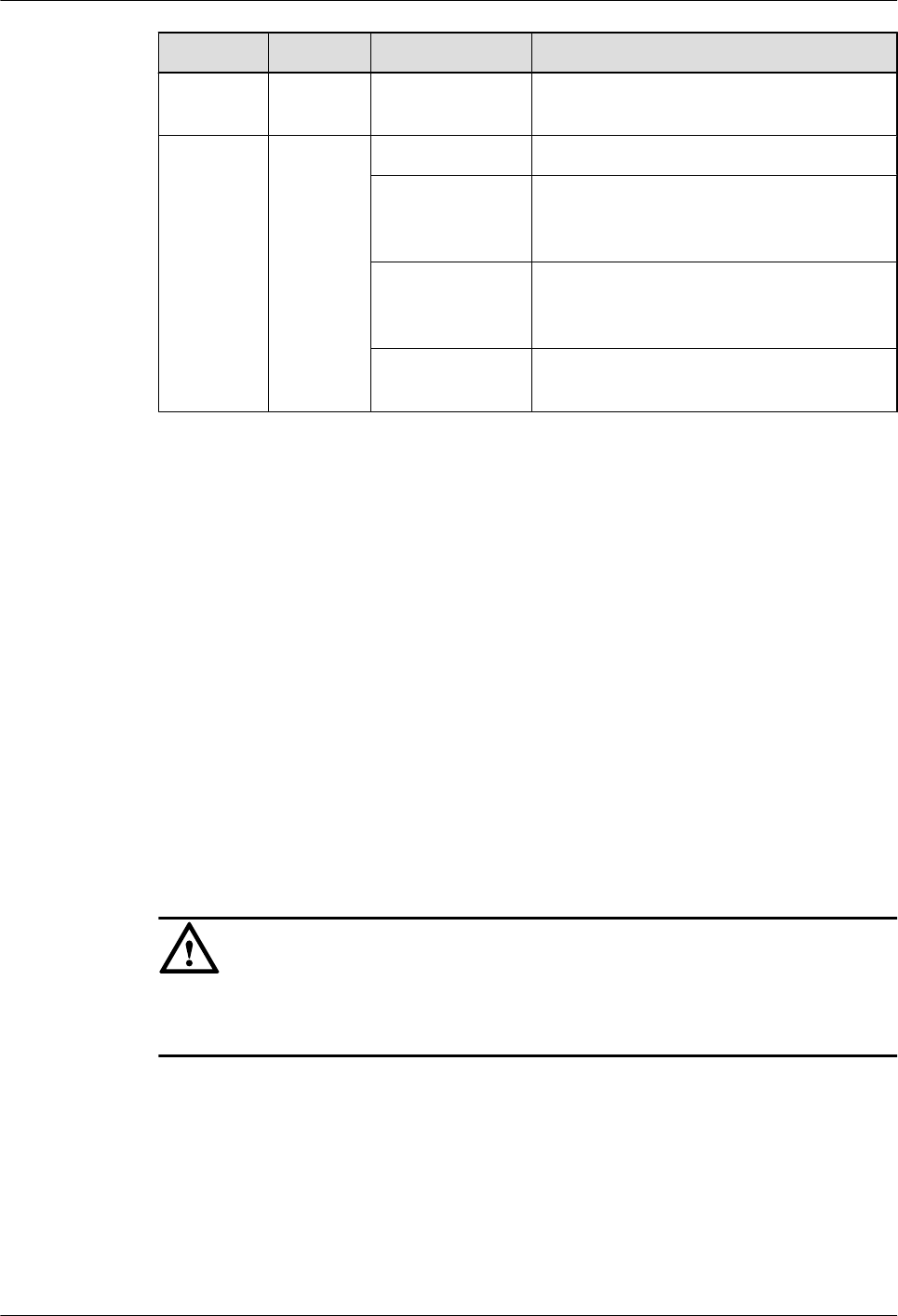
CAUTION
In improper installation scenarios, the heat dissipation efficiency decreases and therefore the
RRU may not work properly. Figure 3-6 shows an improper installation scenario.
RRU3260
Installation Guide 3 Information About the Installation
Issue () Huawei Proprietary and Confidential
Copyright © Huawei Technologies Co., Ltd.
12
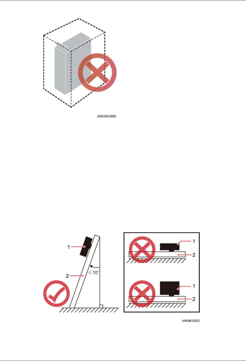
Figure 3-6 Improper installation scenario
Method of installation:
lTo ensure proper heat dissipation and waterproofing of the RRU, the RRU must be installed
with the ports at the bottom and the vertical deviation angle of the RRU must be less than
or equal to 10 degrees, as shown in Figure 3-7.
lThe side-mounted mode is recommended for RRUs on the main pole secured on a tower.
This installation mode allows multiple RRUs to be installed next to each other at the same
level on a pole. When the horizontal distance between the main and auxiliary poles on a
tower is equal to or greater than 810 mm (23.62 in.), the side-mounted mode is
recommended for installing RRUs on the auxiliary pole to meet the minimum clearance
requirements. Otherwise, the standard mode is recommended for installing RRUs on the
auxiliary pole.
Figure 3-7 Requirements for the vertical deviation angle of an RRU
(1) RRU (2) Installation support (pole, U-steel, angle steel, or wall)
RRU3260
Installation Guide 3 Information About the Installation
Issue () Huawei Proprietary and Confidential
Copyright © Huawei Technologies Co., Ltd.
13
Installing an RRU on a Pole
Figure 3-8 shows the diameter of a pole for installing an RRU.
Figure 3-8 Diameter of a pole
CAUTION
lThe diameter of a pole for installing an RRU ranges from 60 mm (2.36 in.) to 114 mm (4.49
in.). The recommended diameter is 80 mm (3.15 in.).
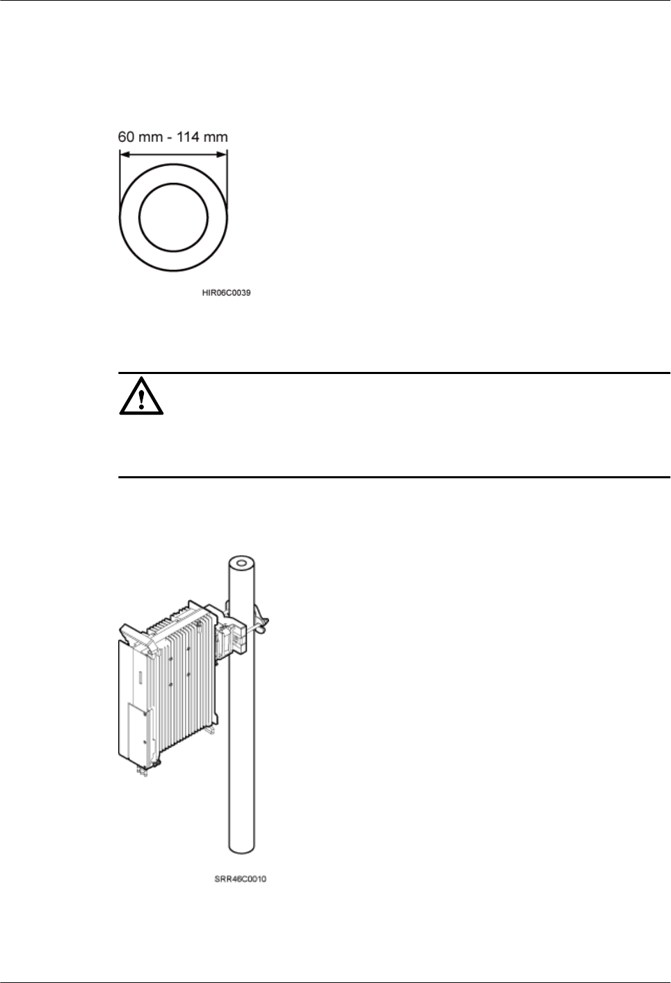
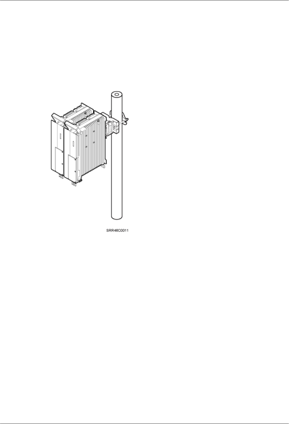
Figure 3-9 shows a single RRU installed on a pole.
Figure 3-9 A single RRU installed on a pole
Figure 3-10 shows two RRUs installed on a pole.
RRU3260
Installation Guide 3 Information About the Installation
Issue () Huawei Proprietary and Confidential
Copyright © Huawei Technologies Co., Ltd.
14
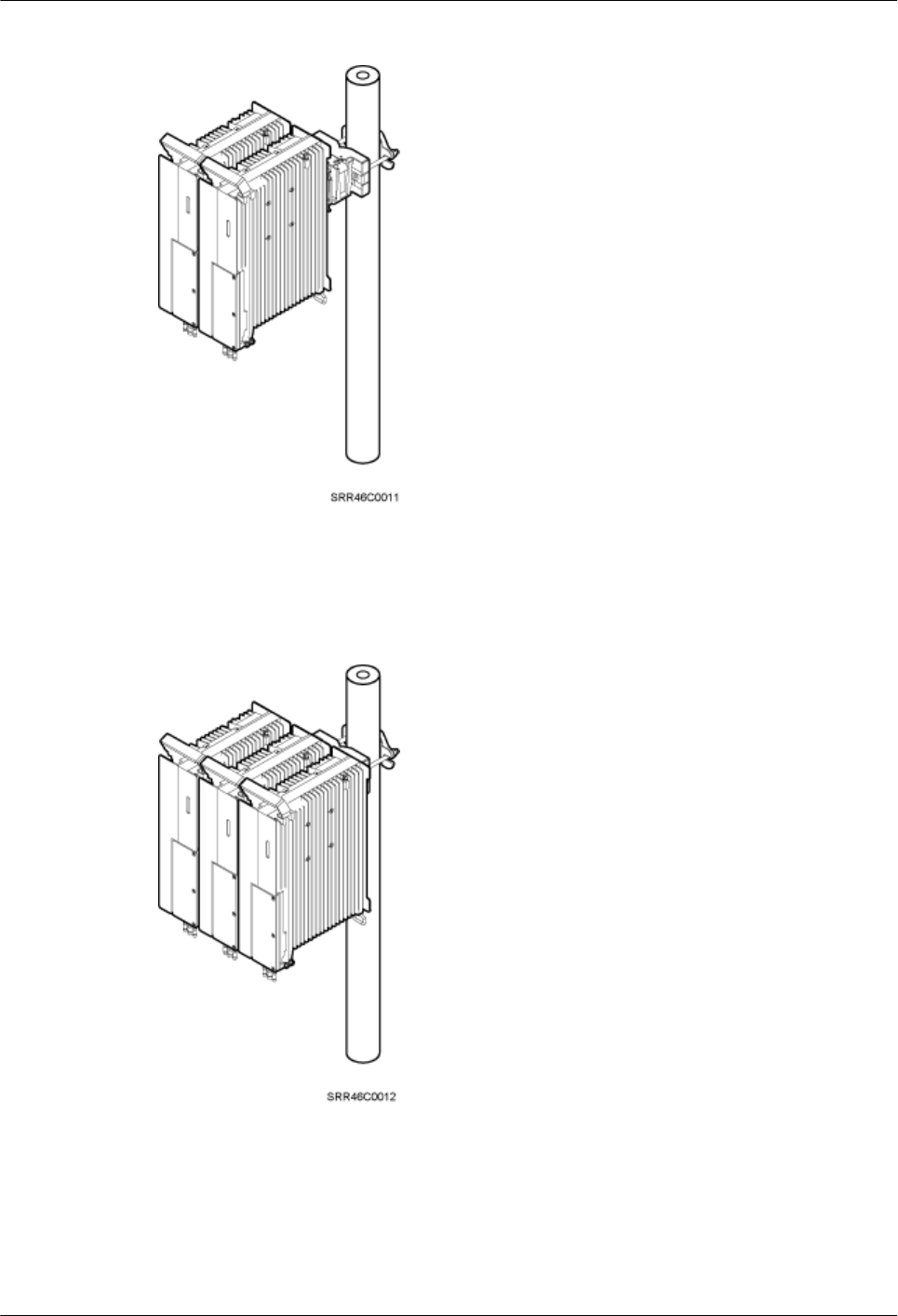
Figure 3-10 Two RRUs installed on a pole
Figure 3-11, Figure 3-12, and Figure 3-14 show three or more RRUs installed on a pole.
Figure 3-11 Three RRUs installed on a pole
RRU3260
Installation Guide 3 Information About the Installation
Issue () Huawei Proprietary and Confidential
Copyright © Huawei Technologies Co., Ltd.
15
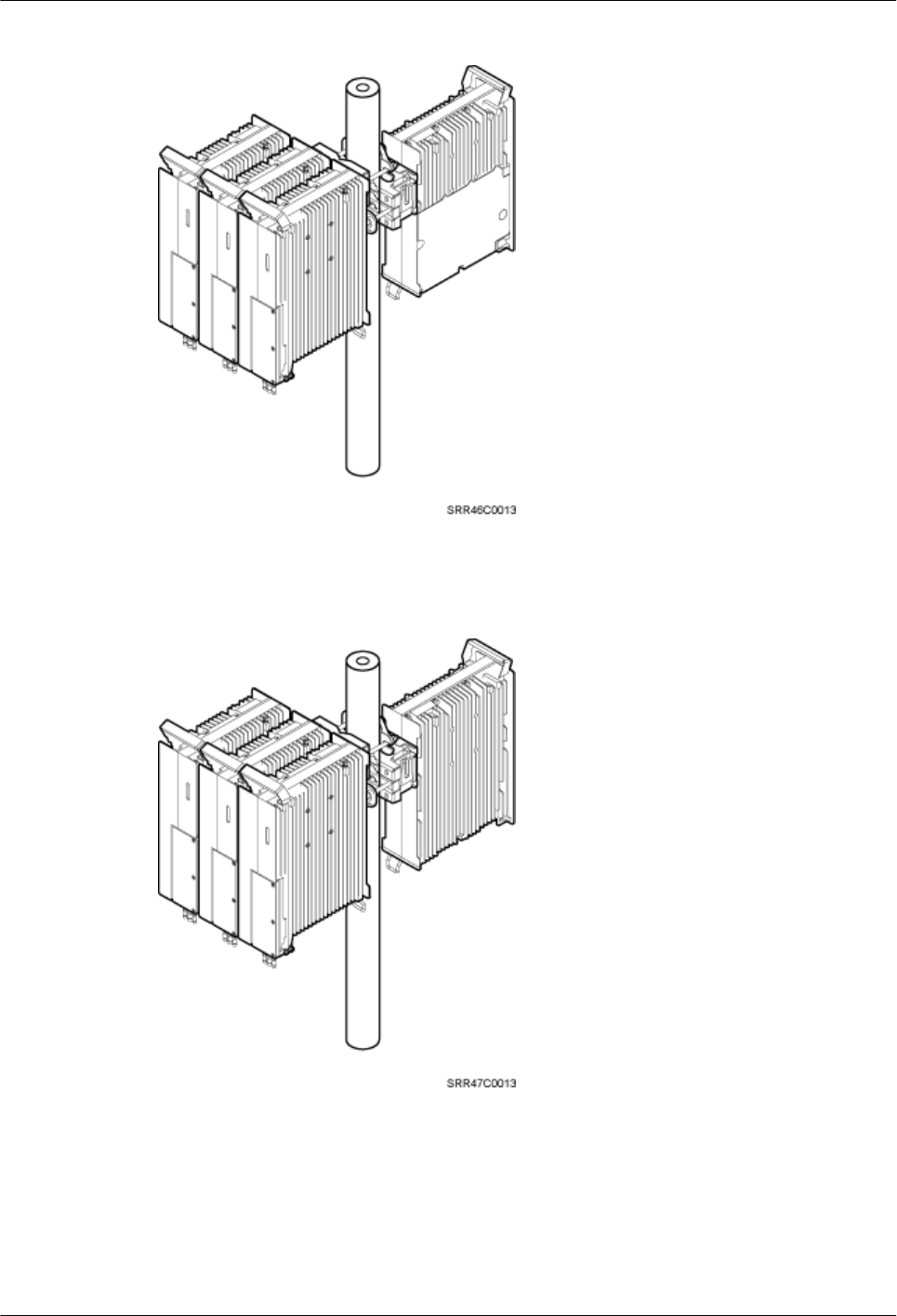
Figure 3-12 Four RRUs installed on a pole
Figure 3-13 Four RRUs installed on a pole
RRU3260
Installation Guide 3 Information About the Installation
Issue () Huawei Proprietary and Confidential
Copyright © Huawei Technologies Co., Ltd.
16
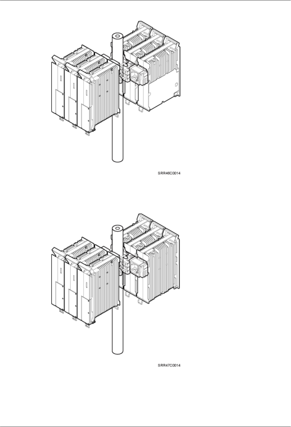
Figure 3-14 Six RRUs installed on a pole
Figure 3-15 Six RRUs installed on a pole
Installing an RRU on U-steel
Figure 3-16 shows U-steel specifications.
RRU3260
Installation Guide 3 Information About the Installation
Issue () Huawei Proprietary and Confidential
Copyright © Huawei Technologies Co., Ltd.
17
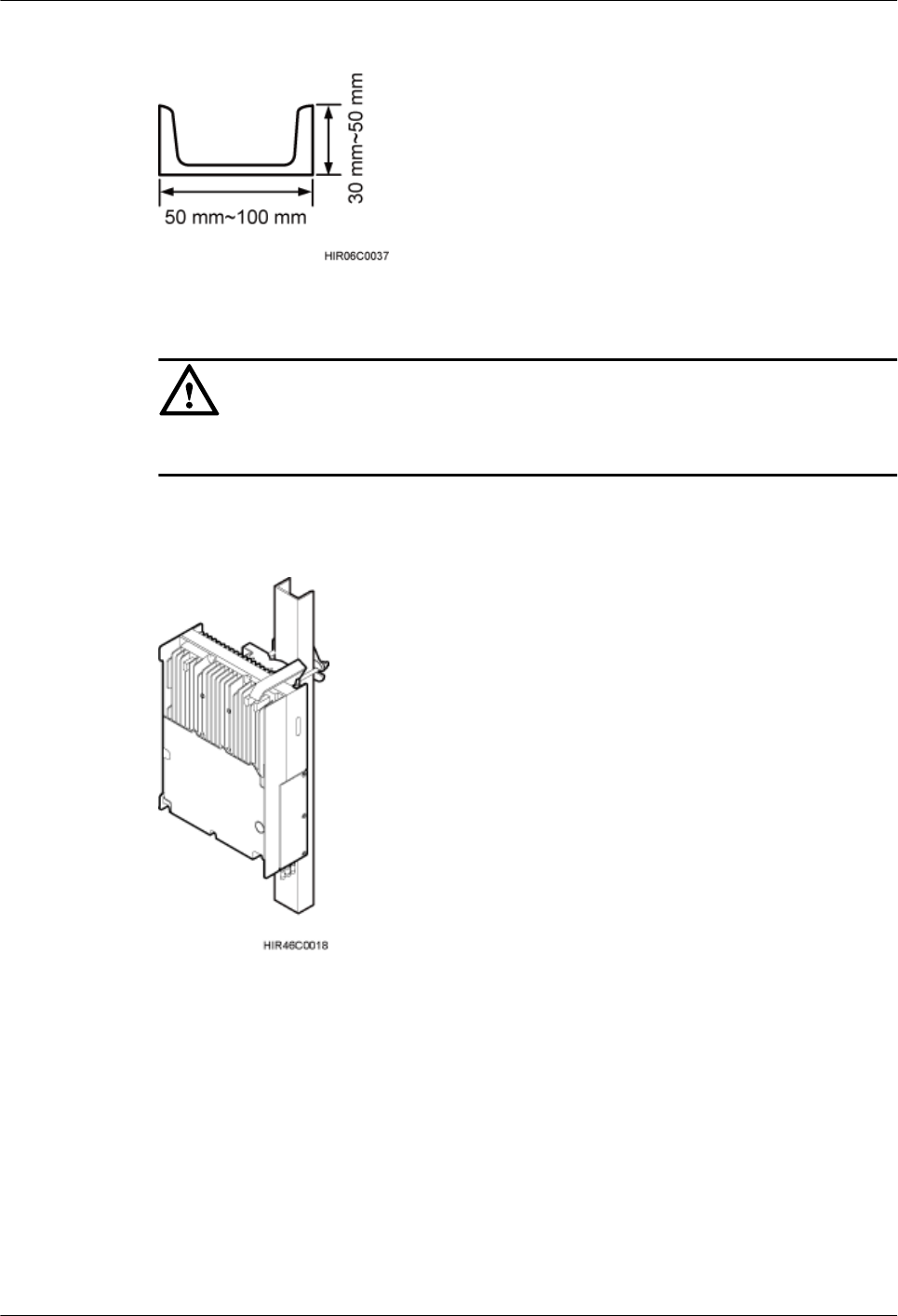
Figure 3-16 U-steel specifications
CAUTION
U-steel supports the standard or reverse installation of a single RRU only.
Figure 3-17 shows an RRU installed on U-steel.
Figure 3-17 RRU installed on U-steel
RRU3260
Installation Guide 3 Information About the Installation
Issue () Huawei Proprietary and Confidential
Copyright © Huawei Technologies Co., Ltd.
18
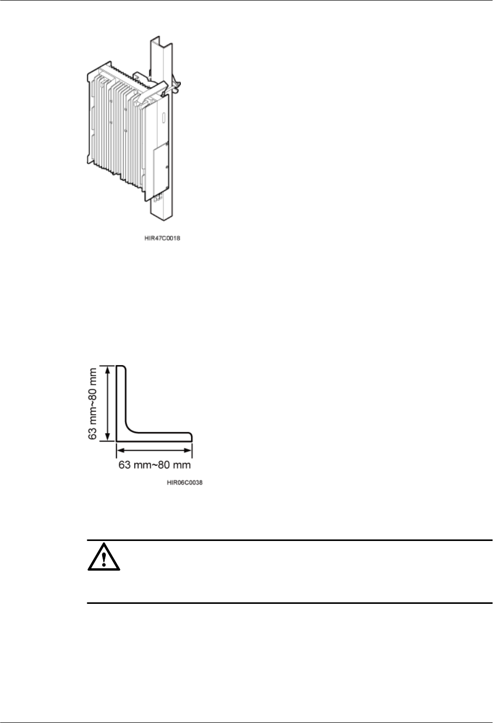
Figure 3-18 RRU installed on U-steel
Installing an RRU on Angle Steel
Figure 3-19 shows angle steel specifications.
Figure 3-19 Angle steel specifications
CAUTION
Angle steel supports the standard or reverse installation of a single RRU only.
Figure 3-20 shows an RRU installed on angle steel.
RRU3260
Installation Guide 3 Information About the Installation
Issue () Huawei Proprietary and Confidential
Copyright © Huawei Technologies Co., Ltd.
19
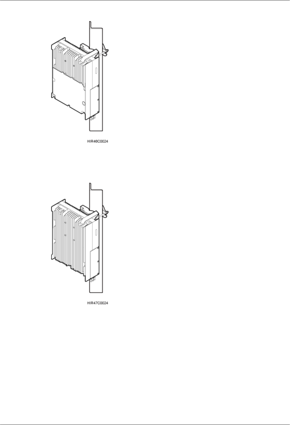
Figure 3-20 RRU installed on angle steel
Figure 3-21 RRU installed on angle steel
Installing an RRU on a Wall
The wall for installing RRUs must meet the following requirements:
lWhen a single RRU is installed, the wall has a capacity of bearing at least four times the
weight of the RRU.
lExpansion anchor bolts must be tightened to 30 N·m (265.52 lbf·in.) so that the bolts stay
secured without damaging the wall.
RRU3260
Installation Guide 3 Information About the Installation
Issue () Huawei Proprietary and Confidential
Copyright © Huawei Technologies Co., Ltd.
20
CAUTION
lIt is recommended that the RRU be installed on a wall in standard mode.
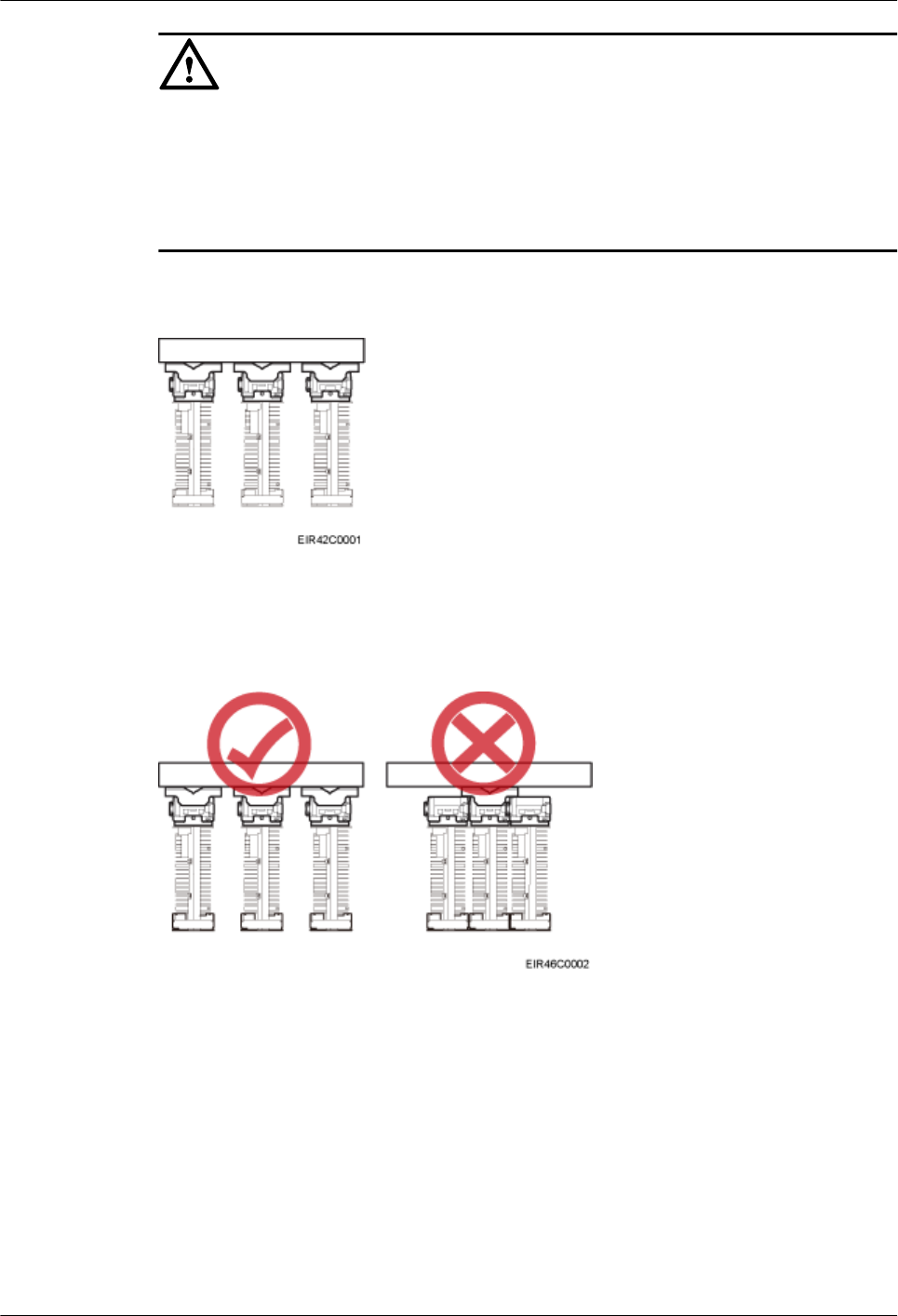
lWhen multiple RRUs are installed on an outdoor wall in side-mounted mode, it is
recommended that the mounting brackets not be combined, as shown in Figure 3-22. When
multiple RRUs are installed on an indoor wall in side-mounted mode, the mounting brackets
cannot be combined, as shown in Figure 3-23.
Figure 3-22 Correct installation of mounting brackets for multiple RRUs installed on an outdoor
wall in side-mounted mode
Figure 3-23 Correct installation of mounting brackets for multiple RRUs installed on an indoor
wall in side-mounted mode
Figure 3-24 shows an RRU installed on a wall.
RRU3260
Installation Guide 3 Information About the Installation
Issue () Huawei Proprietary and Confidential
Copyright © Huawei Technologies Co., Ltd.
21
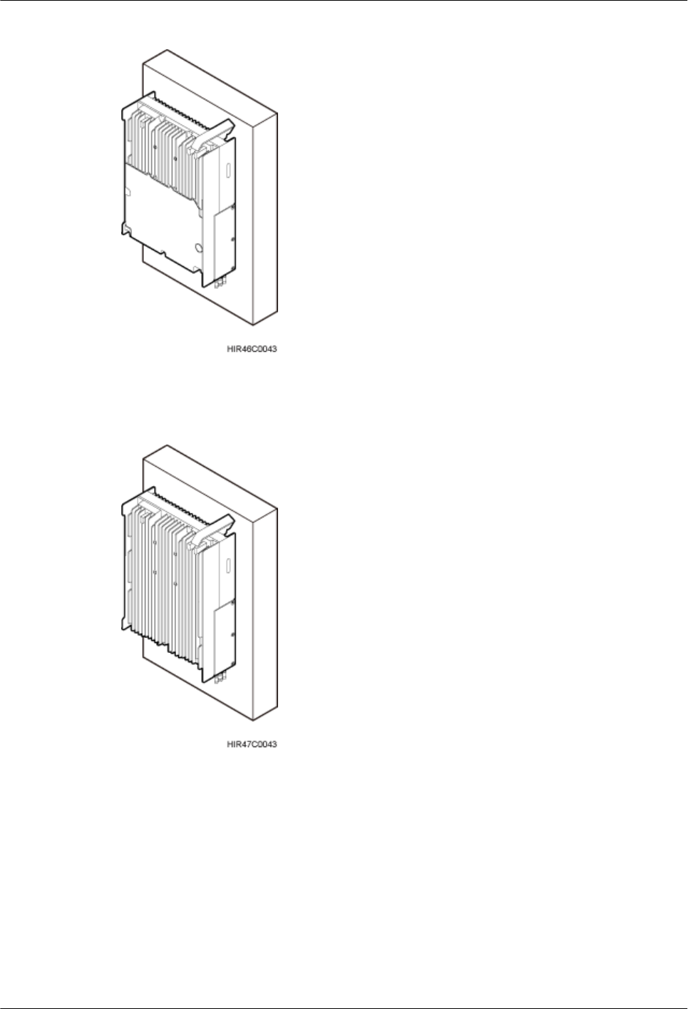
Figure 3-24 RRU installed on a wall
Figure 3-25 RRU installed on a wall
Installing an RRU on an IFS06
In an IFS06 scenario:
lThe upper and lower adjustable beams on an IFS06 can be moved up and down to fit for
heights of RRUs.
lThe IFS06 supports at least three RRUs when the ambient temperature is higher than or
equal to the lowest operating temperature of the RRU and at least 5°C (41°F) lower than
the highest operating temperature of the RRU. The IFS06 supports a maximum of six RRUs
when the ambient temperature is higher than or equal to the lowest operating temperature
RRU3260
Installation Guide 3 Information About the Installation
Issue () Huawei Proprietary and Confidential
Copyright © Huawei Technologies Co., Ltd.
22
of the RRU and at least 10°C (50°F) lower than the highest operating temperature of the
RRU.
NOTE
For details about the operating temperature of the RRU, see section "Technical Specifications of
RRUs" in 3900 Series Base Station Technical Description.
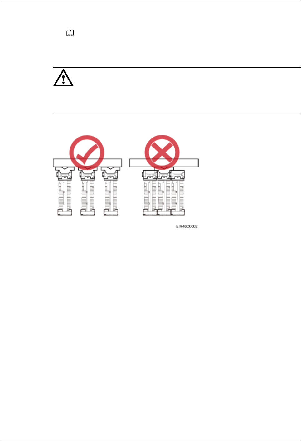
CAUTION
The mounting brackets for multiple RRUs cannot be combined when the RRUs are installed on
an IFS06, as shown in Figure 3-26.
Figure 3-26 Correct installation of mounting brackets for RRUs installed on an IFS06
Figure 3-27 and Figure 3-28 show RRUs installed on an IFS06.
RRU3260
Installation Guide 3 Information About the Installation
Issue () Huawei Proprietary and Confidential
Copyright © Huawei Technologies Co., Ltd.
23
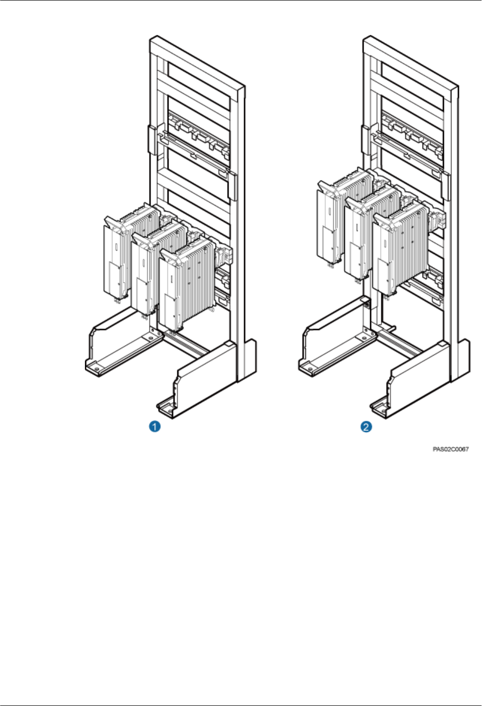
Figure 3-27 Three RRUs installed on an IFS06
(1) Height-restricted scenario (2) Height-unrestricted scenario
RRU3260
Installation Guide 3 Information About the Installation
Issue () Huawei Proprietary and Confidential
Copyright © Huawei Technologies Co., Ltd.
24
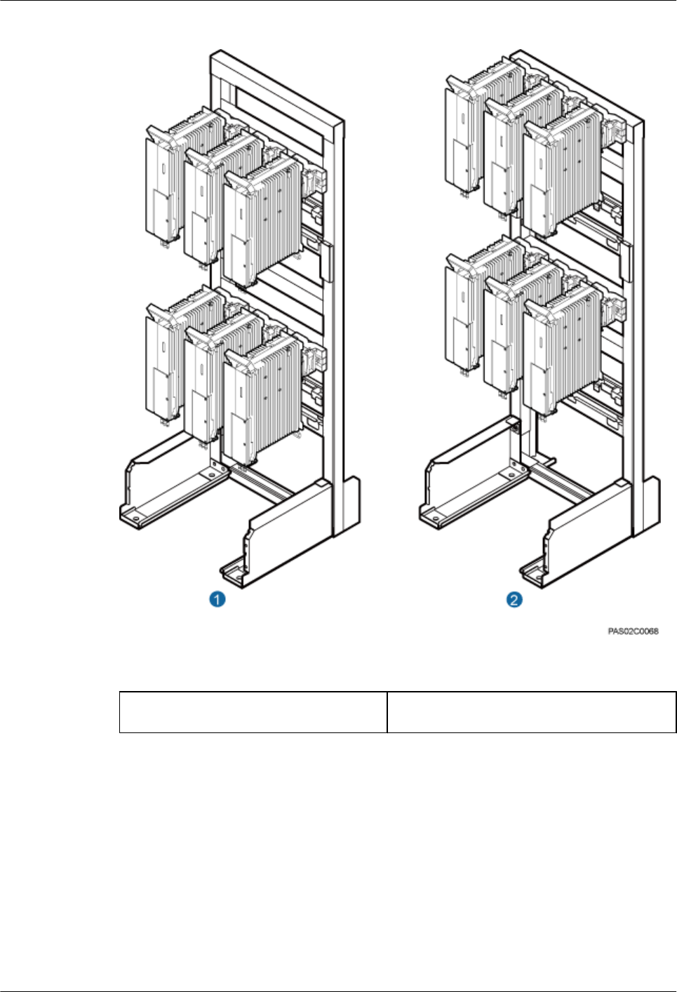
Figure 3-28 Six RRUs installed on an IFS06
(1) Height-restricted scenario (2) Height-unrestricted scenario
3.5 Installation Clearance Requirements of an RRU
This section describes the requirements for the installation clearance of a single RRU and
multiple RRUs and the requirements for the installation spacing between RRUs.
3.5.1 Clearance for a Single RRU
This section describes the recommended and minimum clearance for a single RRU.
RRU3260
Installation Guide 3 Information About the Installation
Issue () Huawei Proprietary and Confidential
Copyright © Huawei Technologies Co., Ltd.
25
NOTE
lThe recommended clearance ensures normal running and provides an appropriate space for operation
and maintenance (OM). If there is sufficient space, leave the recommended clearance after installing
the equipment.
lThe minimum clearance ensures normal running and heat dissipation, but OM activities such as
checking indicator status and opening the cabling cavity cannot be properly conducted. If the
installation space is restricted, leave the minimum clearance after installing the equipment.
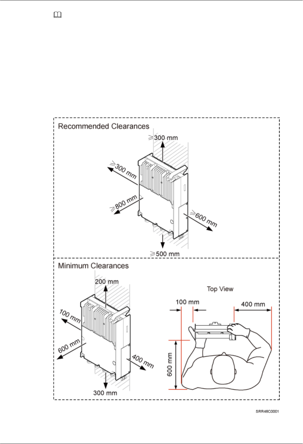
Clearances for a Single RRU in Standard or Reverse Mode
Figure 3-29 shows the clearances for a single RRU in standard or reverse mode.
Figure 3-29 Clearances for a single RRU in standard or reverse mode
RRU3260
Installation Guide 3 Information About the Installation
Issue () Huawei Proprietary and Confidential
Copyright © Huawei Technologies Co., Ltd.
26
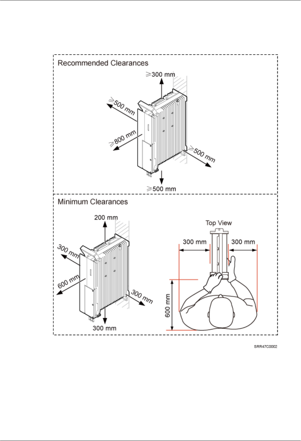
Clearances for a Single RRU in Side-Mounted Mode
Figure 3-30 shows the clearances for a single RRU in side-mounted mode.
Figure 3-30 Clearances for a single RRU in side-mounted mode
Clearances for a Single Tower-mounted RRU
Figure 3-31 and Figure 3-32 show the clearances for a single tower-mounted RRU in standard
or reverse mode and in side-mounted mode, respectively.
RRU3260
Installation Guide 3 Information About the Installation
Issue () Huawei Proprietary and Confidential
Copyright © Huawei Technologies Co., Ltd.
27
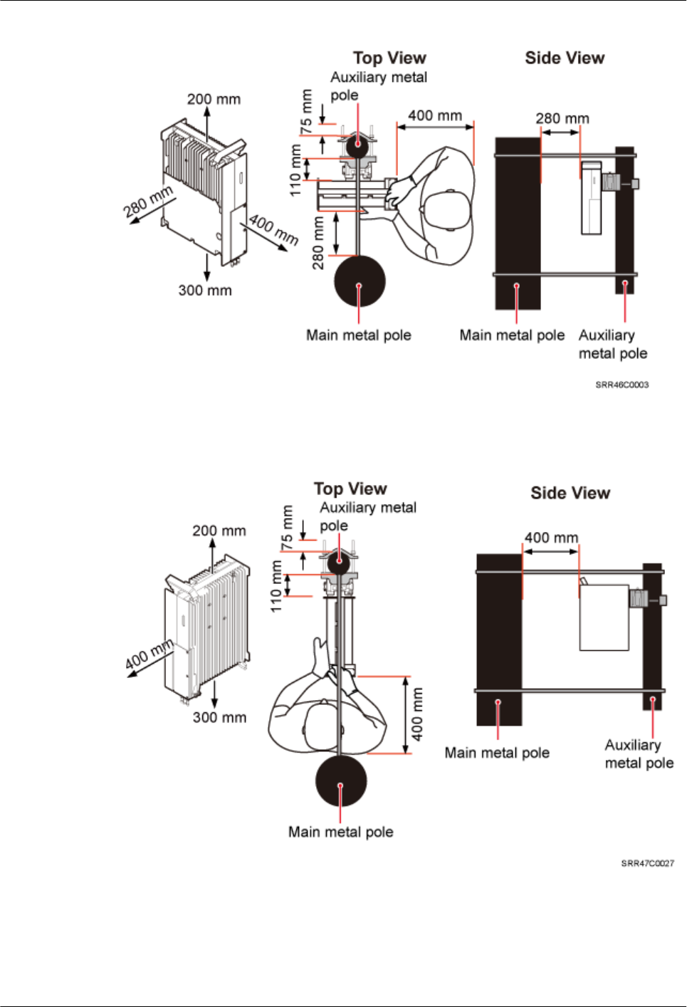
Figure 3-31 Minimum clearance for a single tower-mounted RRU in standard or reverse mode
Figure 3-32 Minimum clearance for a single tower-mounted RRU in side-mounted mode
3.5.2 Clearance for Multiple RRUs
This section describes the recommended and minimum clearance for multiple RRUs.
RRU3260
Installation Guide 3 Information About the Installation
Issue () Huawei Proprietary and Confidential
Copyright © Huawei Technologies Co., Ltd.
28
NOTE
lThe recommended clearance ensures normal running and provides an appropriate space for operation
and maintenance (OM). If there is sufficient space, leave the recommended clearance after installing
the equipment.
lThe minimum clearance ensures normal running and heat dissipation, but OM activities such as
checking indicator status and opening the cabling cavity cannot be properly conducted. If the
installation space is restricted, leave the minimum clearance after installing the equipment.
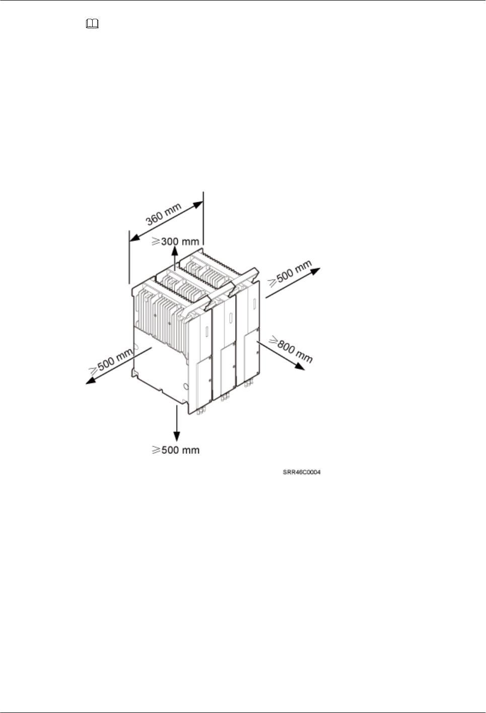
Recommended Clearance for Multiple RRUs Installed in Centralized Mode
Figure 3-33 shows the recommended clearance for multiple RRUs installed in centralized mode.
Figure 3-33 Recommended clearances for three or more RRUs installed on a pole
Minimum Clearance for Multiple RRUs Installed in Centralized Mode
Figure 3-34 shows the minimum clearance for multiple RRUs installed in centralized mode.
RRU3260
Installation Guide 3 Information About the Installation
Issue () Huawei Proprietary and Confidential
Copyright © Huawei Technologies Co., Ltd.
29
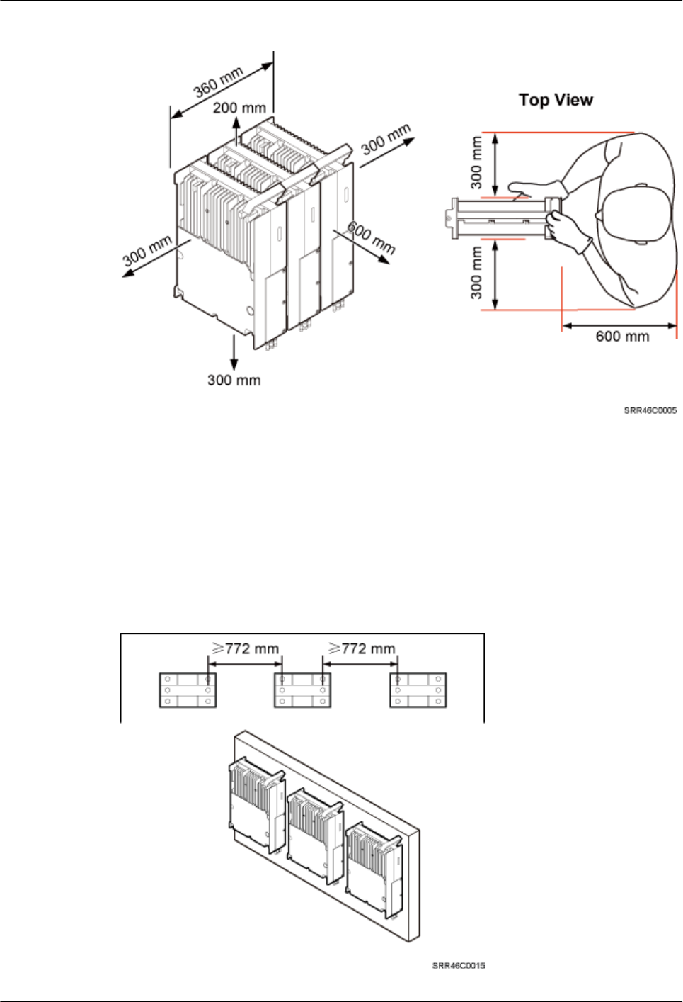
Figure 3-34 Minimum clearances for three or more RRUs installed on a pole
Recommended Clearance for Multiple RRUs Installed on a Wall in Standard Mode
Figure 3-35 shows the recommended clearance for multiple RRUs installed on a wall in standard
mode.
Figure 3-35 Recommended clearances for three or more RRUs installed on a wall in standard
mode
RRU3260
Installation Guide 3 Information About the Installation
Issue () Huawei Proprietary and Confidential
Copyright © Huawei Technologies Co., Ltd.
30
Minimum Clearance for Multiple RRUs Installed on a Wall in Standard Mode
Figure 3-36 shows the minimum clearance for multiple RRUs installed on a wall in standard
mode.
Figure 3-36 Minimum clearances for three or more RRUs installed on a wall in standard mode
Recommended Clearance for Multiple RRUs Side-Mounted on a Wall
Figure 3-37 shows the recommended clearance for multiple RRUs side-mounted on a wall.
RRU3260
Installation Guide 3 Information About the Installation
Issue () Huawei Proprietary and Confidential
Copyright © Huawei Technologies Co., Ltd.
31
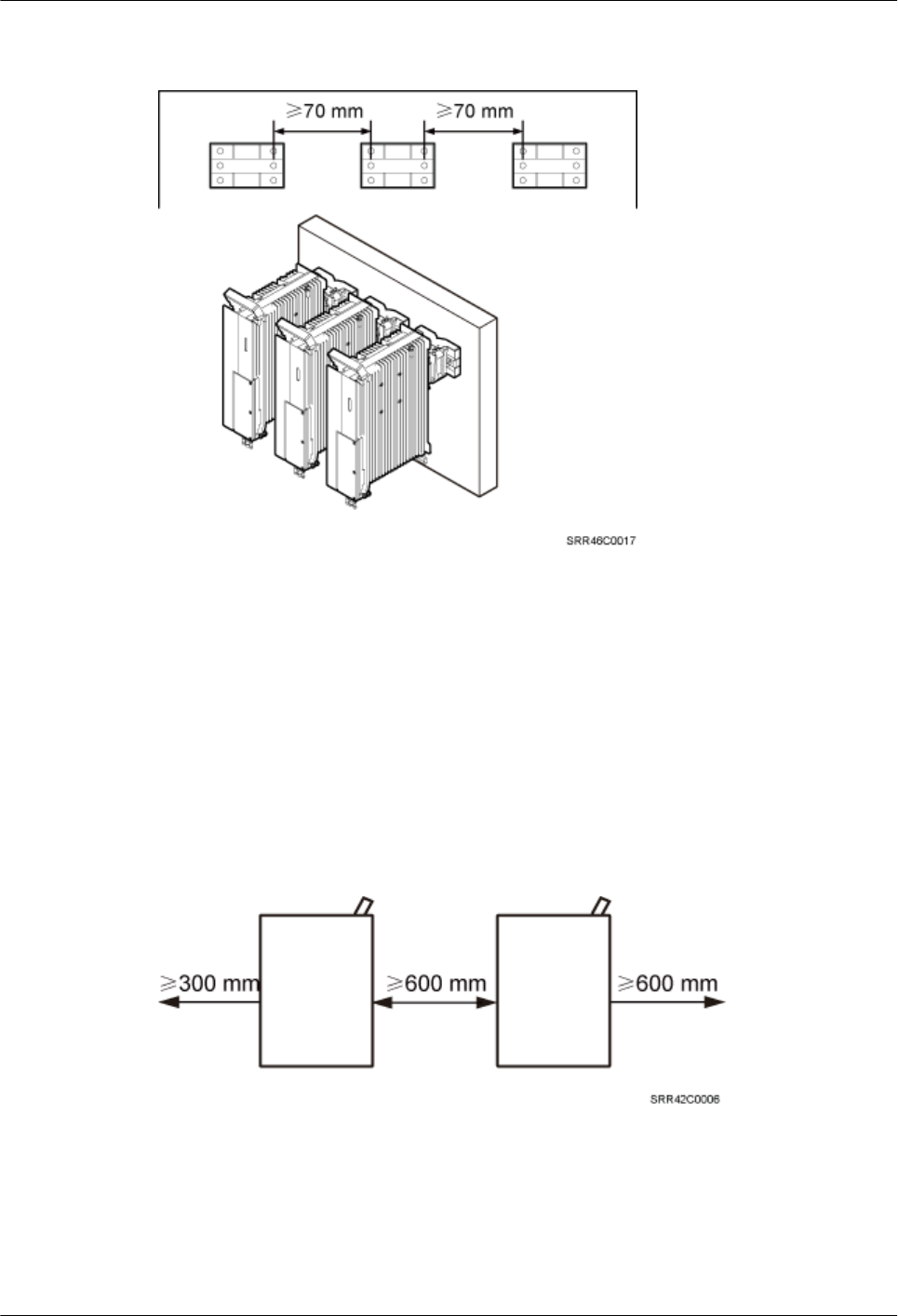
Figure 3-37 Recommended clearances for three or more RRUs installed on a wall in side-
mounted mode
3.5.3 Installation Spacing Between RRUs
This section describes the horizontal and vertical spacing between RRUs.
Recommended Horizontal Spacing Between RRUs
Figure 3-38 shows the recommended horizontal spacing between RRUs.
Figure 3-38 Recommended horizontal spacing between RRUs
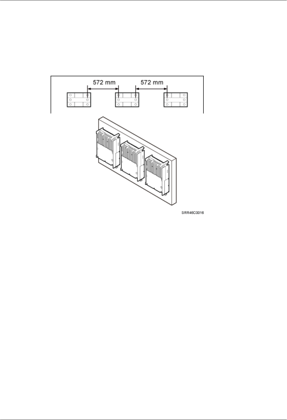
Minimum Horizontal Spacing Between RRUs
Figure 3-39 shows the minimum horizontal spacing between RRUs.
RRU3260
Installation Guide 3 Information About the Installation
Issue () Huawei Proprietary and Confidential
Copyright © Huawei Technologies Co., Ltd.
32
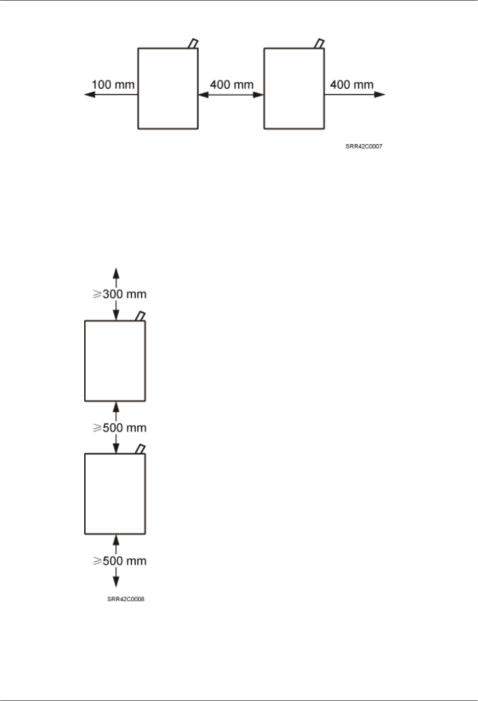
Figure 3-39 Minimum horizontal spacing between RRUs
Recommended Vertical Spacing Between RRUs
Figure 3-40 shows the recommended vertical spacing between RRUs.
Figure 3-40 Recommended vertical spacing between RRUs
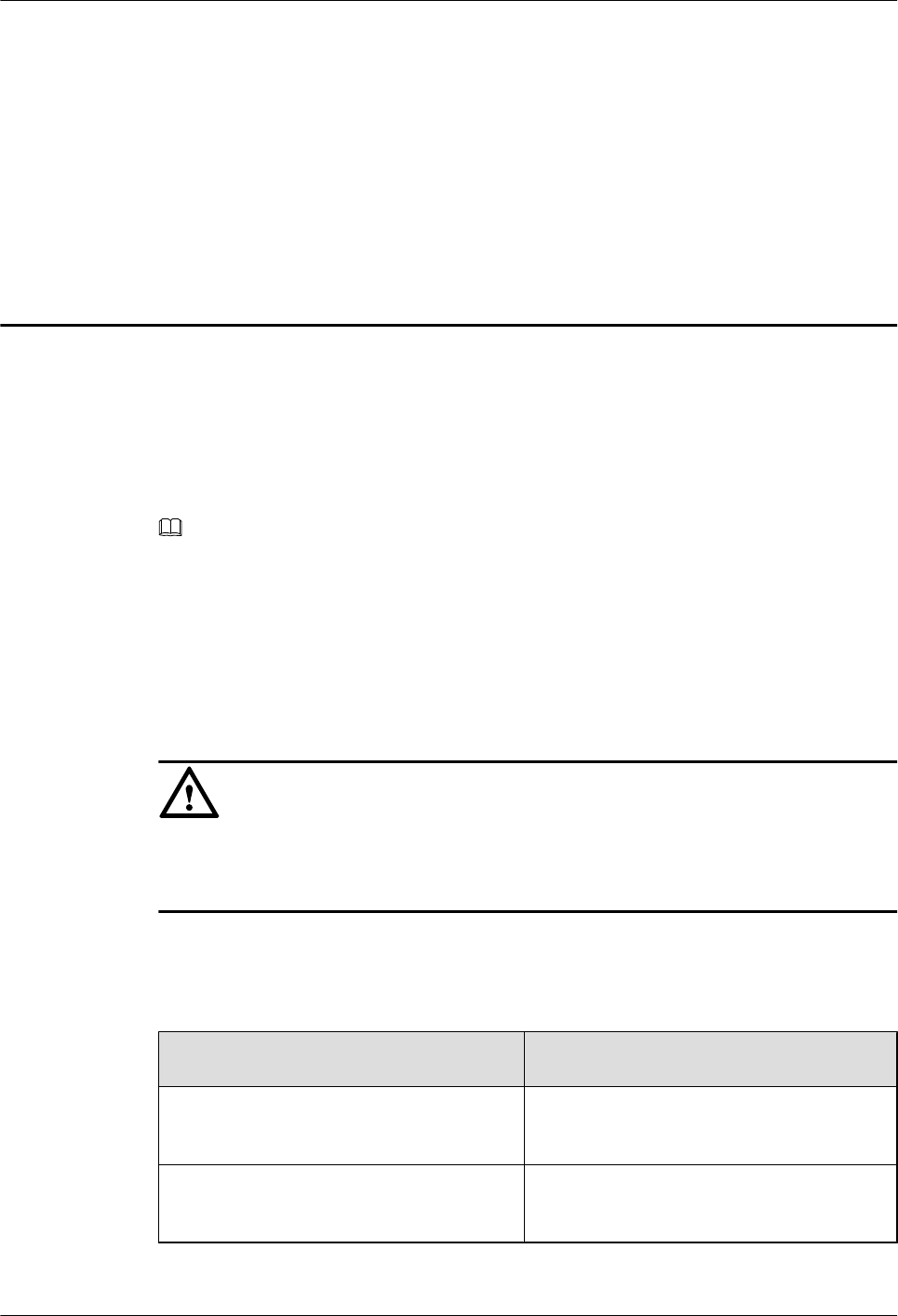
Minimum Vertical Spacing Between RRUs
Figure 3-41 shows the minimum vertical spacing between RRUs.
RRU3260
Installation Guide 3 Information About the Installation
Issue () Huawei Proprietary and Confidential
Copyright © Huawei Technologies Co., Ltd.
33
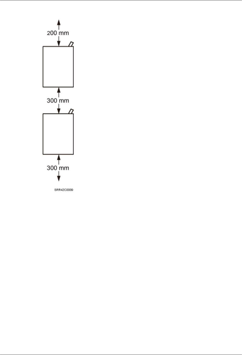
Figure 3-41 Minimum vertical spacing between RRUs
RRU3260
Installation Guide 3 Information About the Installation
Issue () Huawei Proprietary and Confidential
Copyright © Huawei Technologies Co., Ltd.
34
4 Unpacking the Equipment
This chapter describes how to unpack and check the delivered equipment to ensure that all the
materials are included and intact.
Context
NOTE
When transporting, moving, or installing the equipment, components, or parts, you must:
lEnsure that they are transported in the delivered packages instead of being unpacked or in non-
standard packages. If boards are used for a trial and then transported to sites, pack the boards again
before transportation.
lPrevent them from colliding with doors, walls, shelves, or other objects.
lWear clean gloves, and avoid touching the equipment, components, or parts with bare hands, sweat-
soaked gloves, or dirty gloves.
CAUTION
lAfter a cabinet or an BBU is unpacked, it must be powered on within 7 days.
lAfter an RRU is unpacked, it must be powered on within 24 hours.
Procedure
Step 1 Check the total number of articles in each case according to the packing list.
If ... Then ...
The total number tallies with the packing
list
Go to Step 2.
The total number does not tally with the
packing list
Find out the cause and report any missing
articles to the local Huawei office.
Step 2 Check the exterior of the packing case.
RRU3260
Installation Guide 4 Unpacking the Equipment
Issue () Huawei Proprietary and Confidential
Copyright © Huawei Technologies Co., Ltd.
35
If ... Then ...
The outer packing is intact Go to Step 3.
The outer packing is severely damaged or
soaked
Find out the cause and report it to the local
Huawei office.
The shockwatch label is red Stop unpacking the wooden crate, and then
report it to the transportation company.
Step 3 Check the type and quantity of the equipment in the cases according to the packing list.
If ... Then ...
Types and quantity of the article tally with
those on the packing list
Sign the Packing List with the customer.
Either shipment shortage, wrong shipment
or damaged articles.
Report to the local Huawei office.
WARNING
To protect the equipment and prevent damage to the equipment, you are advised to keep the
unpacked equipment and packing materials indoors, take photos of the stocking environment,
packing case or carton, packing materials, and any rusted or eroded equipment, and then file the
photos.
----End
RRU3260
Installation Guide 4 Unpacking the Equipment
Issue () Huawei Proprietary and Confidential
Copyright © Huawei Technologies Co., Ltd.
36
5 Installation Process
The installation process involves installing an RRU and RRU cables, checking the RRU
hardware installation, and powering on the RRU.
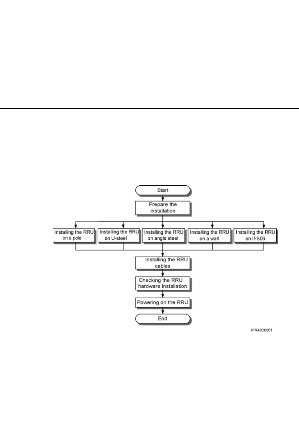
Figure 5-1 shows the process of installing an RRU.
Figure 5-1 Process of installing an RRU
RRU3260
Installation Guide 5 Installation Process
Issue () Huawei Proprietary and Confidential
Copyright © Huawei Technologies Co., Ltd.
37
6 (Optional) Installing the Plastic Shells of the
RRU
This section describes the procedure for installing the plastic shells of the RRU.
Context
An RRU is equipped with a plastic shell only when necessary.
Procedure
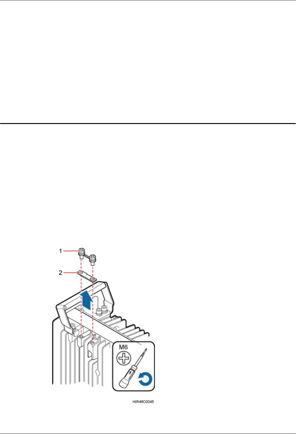
Step 1 Use an M6 Phillips screwdriver to loosen the two screws on the metal sheet of the RRU and
remove the metal sheet, as shown in Figure 6-1.
Figure 6-1 Removing the metal sheet
RRU3260
Installation Guide 6 (Optional) Installing the Plastic Shells of the RRU
Issue () Huawei Proprietary and Confidential
Copyright © Huawei Technologies Co., Ltd.
38
(1) Screw (2) Metal sheet
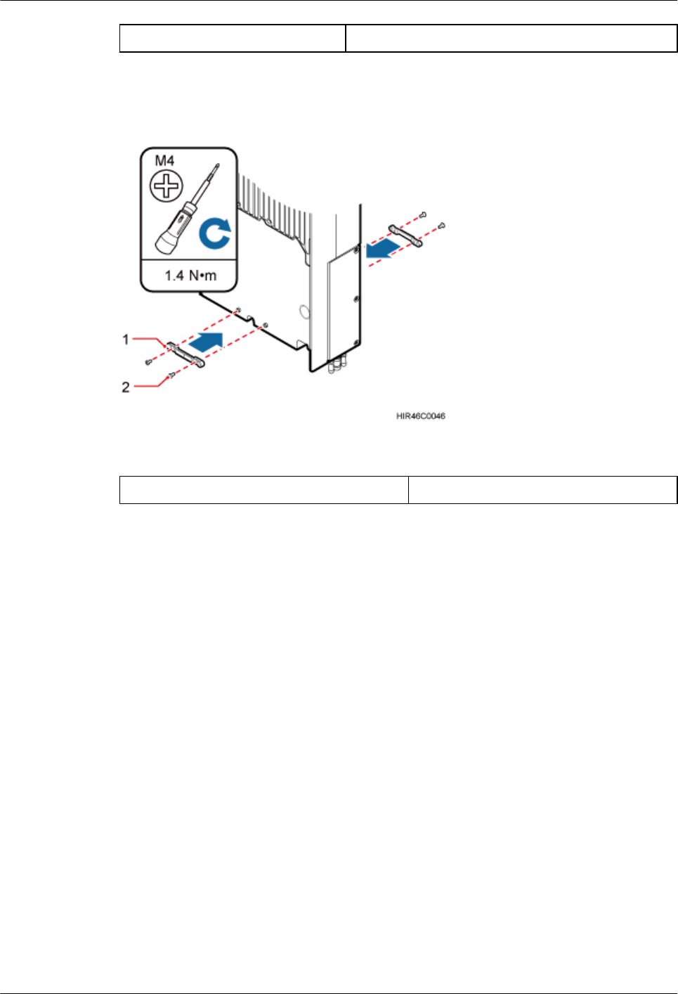
Step 2 Install a buckle on each side at the bottom of the RRU, and use an M4 torque wrench to tighten
the screws on the buckles to 1.4 N•m (12.39 lbf•in.), as shown in Figure 6-2.
Figure 6-2 Installing buckles at the bottom
(1) Buckle (2) Screw
Step 3 Use four hex screws to secure the plastic shells onto the RRU and use an M6 hex key wrench
to tighten the screws to 2.8 N•m (24.78 lbf•in.), as shown in Figure 6-3.
RRU3260
Installation Guide 6 (Optional) Installing the Plastic Shells of the RRU
Issue () Huawei Proprietary and Confidential
Copyright © Huawei Technologies Co., Ltd.
39
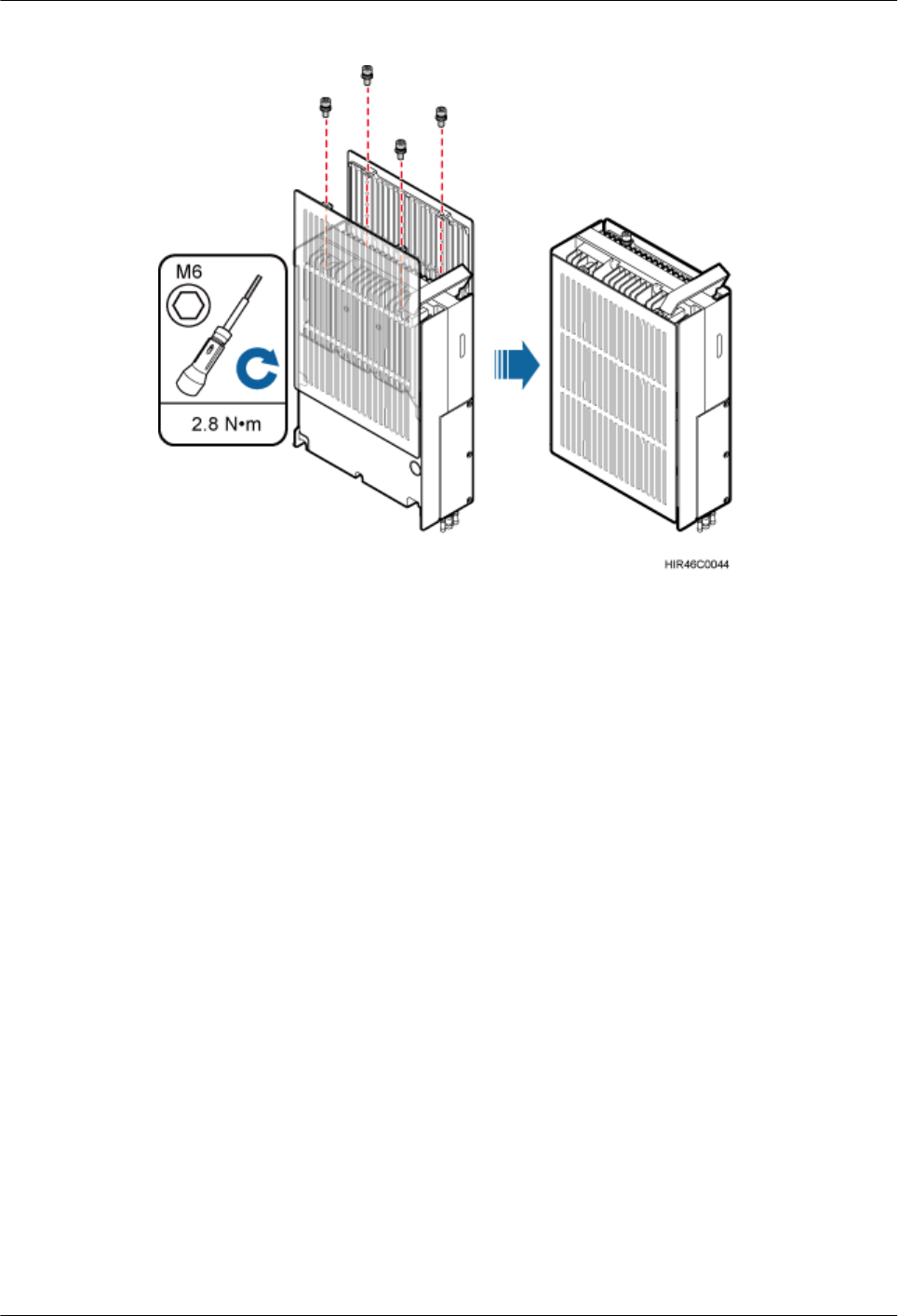
Figure 6-3 Installing the plastic shells of the RRU
----End
RRU3260
Installation Guide 6 (Optional) Installing the Plastic Shells of the RRU
Issue () Huawei Proprietary and Confidential
Copyright © Huawei Technologies Co., Ltd.
40

7 Hoisting an RRU and Related Cables onto a
Tower
About This Chapter
This section describes the procedure for hoisting an RRU and related cables onto a tower and
the precautions that must be taken.
7.1 Hoisting an RRU onto a Tower
This section describes the procedures and precautions for hoisting an RRU and its mounting kits
onto a tower. In tower-mounted scenario, the RRU can be installed on a pole, U-steel, or angle
steel.
7.2 Hoisting Fiber Optic Cables onto a Tower
This section describes the procedure for hoisting fiber optic cables onto a tower and the
precautions that must be taken.
7.3 Hoisting Power Cables onto a Tower
This section describes the procedure for hoisting power cables onto a tower and the precautions
that must be taken.
RRU3260
Installation Guide 7 Hoisting an RRU and Related Cables onto a Tower
Issue () Huawei Proprietary and Confidential
Copyright © Huawei Technologies Co., Ltd.
41
7.1 Hoisting an RRU onto a Tower
This section describes the procedures and precautions for hoisting an RRU and its mounting kits
onto a tower. In tower-mounted scenario, the RRU can be installed on a pole, U-steel, or angle
steel.
Prerequisites
When the RRU is used with an AC/DC power module, you need to install the AC/DC power
module onto the RRU before hoisting the RRU onto a tower. For details about how to install an
AC/DC power module onto the RRU, see Installing an AC/DC Power Module onto an RRU.
CAUTION
lDo not stand the RRU upright because the RF ports cannot support the weight of the RRU.
lPlace a foam pad or cardboard under the RRU to protect the RRU housing from damage
during the installation.
Procedure
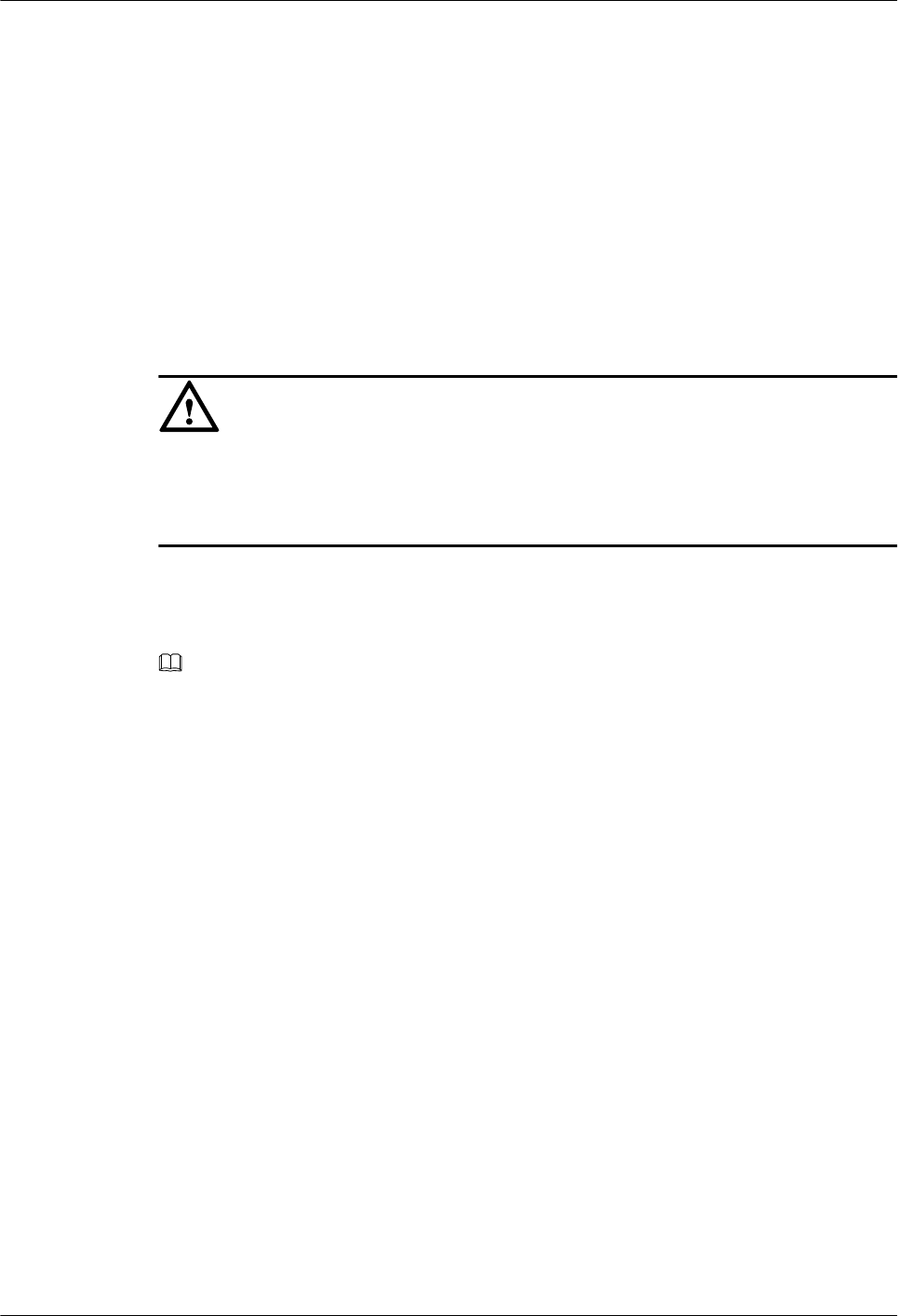
Step 1 Hoist the RRU and mounting kits onto the tower respectively, as shown in Figure 7-1.
NOTE
Hoist mounting kits onto the tower and then install the mounting kits before hoisting the RRU onto the
tower. When hoisting the mounting kits and RRU, protect them from colliding with the tower.
RRU3260
Installation Guide 7 Hoisting an RRU and Related Cables onto a Tower
Issue () Huawei Proprietary and Confidential
Copyright © Huawei Technologies Co., Ltd.
42
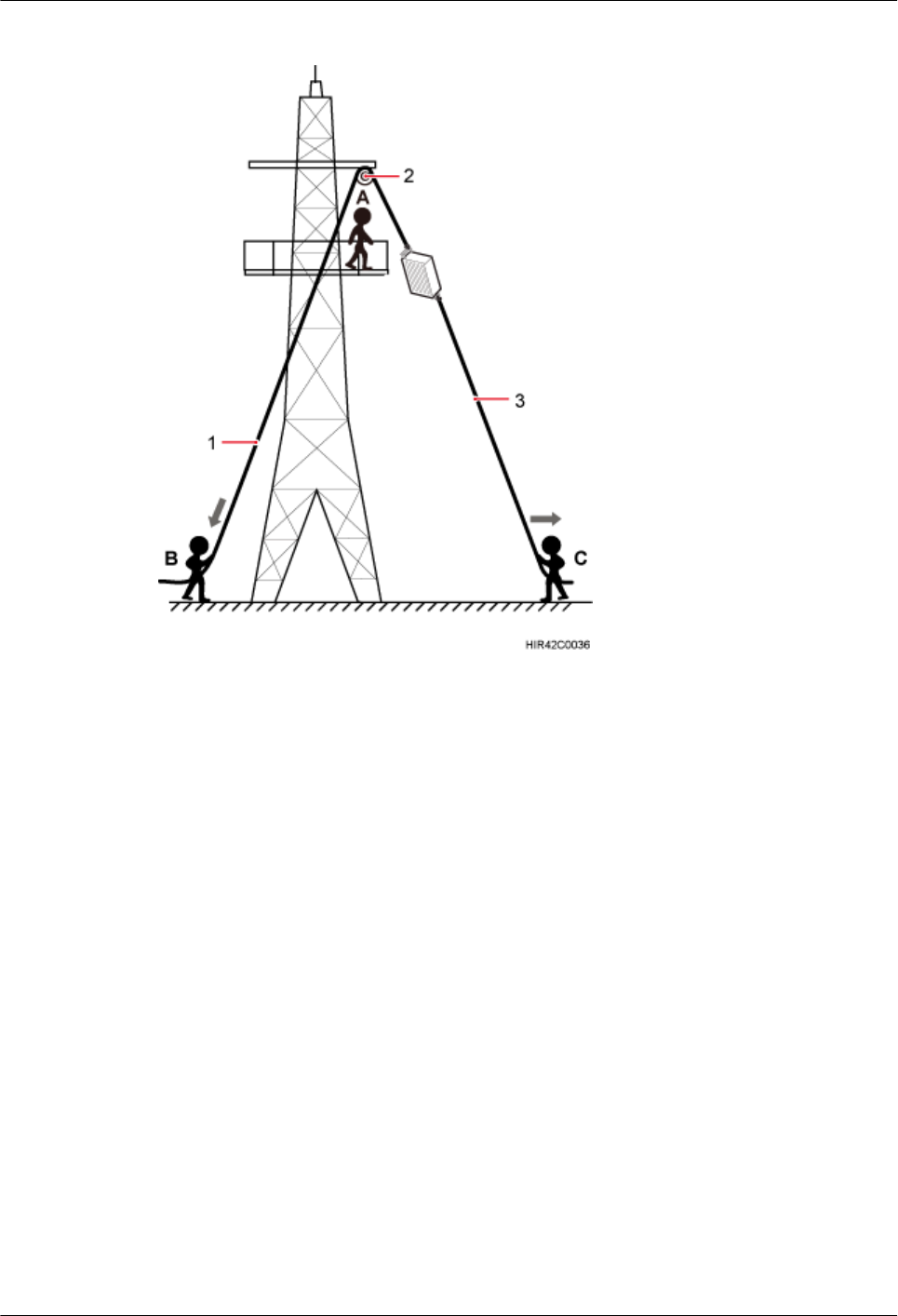
Figure 7-1 Hoisting the RRU onto the tower
(1) Lifting sling (2) Fixed pulley (3) Traction sling
1. After climbing up to the tower, installation engineer A secures the fixed pulley to the tower
platform support and leads the lifting sling through the fixed pulley.
2. Installation engineer C binds the RRU mounting kits properly using a lifting sling, as shown
in Figure 7-2, and binds the RRU using a lifting sling and a traction sling, as shown in
Figure 7-3.
RRU3260
Installation Guide 7 Hoisting an RRU and Related Cables onto a Tower
Issue () Huawei Proprietary and Confidential
Copyright © Huawei Technologies Co., Ltd.
43
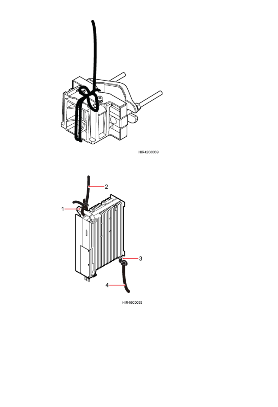
Figure 7-2 Binding mounting kits for the RRU
Figure 7-3 Binding the RRU
(1) Handle (2) Lifting sling (3) Traction eye (4) Traction sling
RRU3260
Installation Guide 7 Hoisting an RRU and Related Cables onto a Tower
Issue () Huawei Proprietary and Confidential
Copyright © Huawei Technologies Co., Ltd.
44
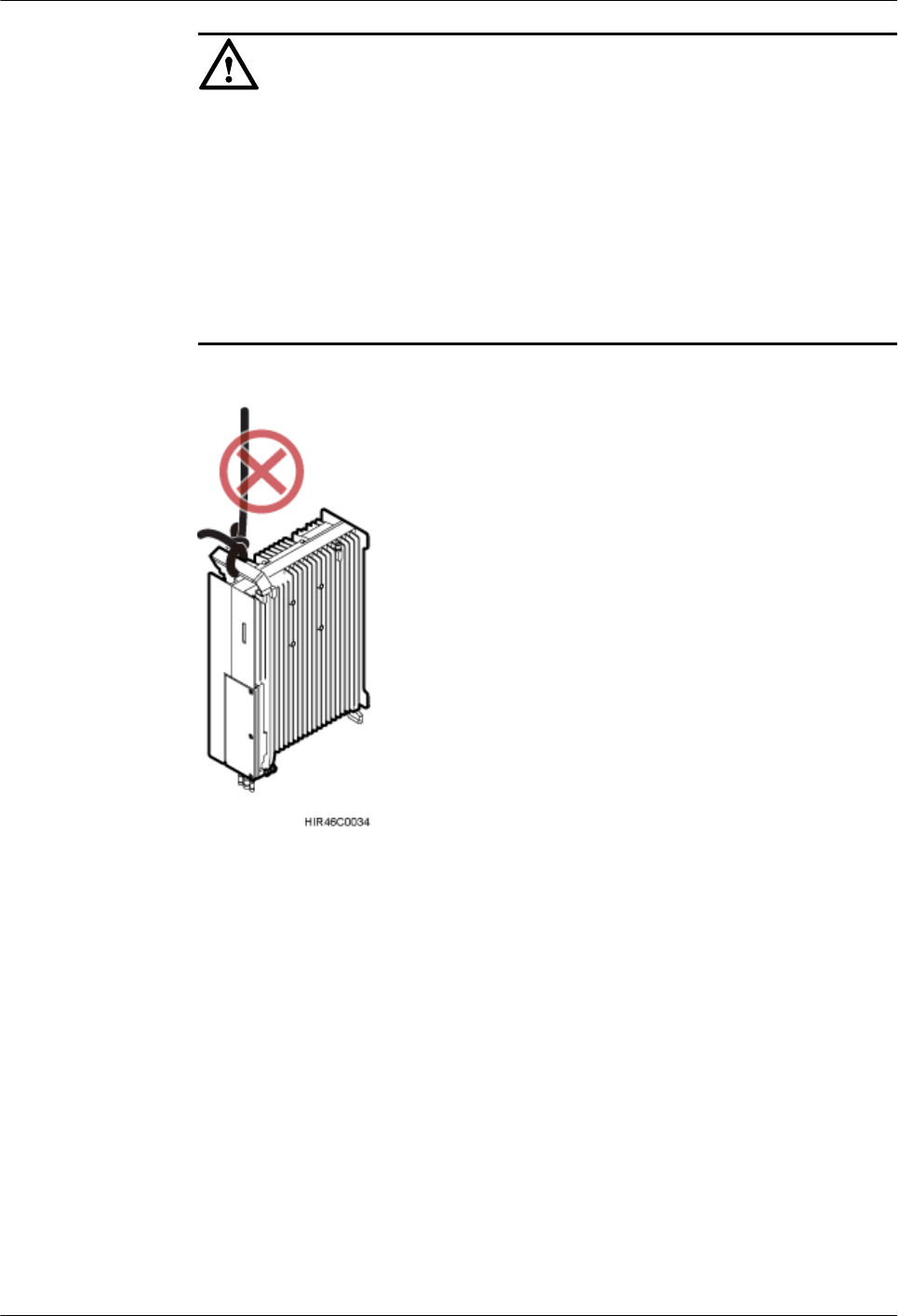
CAUTION
lThe load-bearing capacity of each sling must be greater than 200 kg (441 lb) and the
diameter of each sling must be less than 25 mm (0.98 in.).
lWhen hoisting the RRU onto a tower, protect them from colliding with the tower and
ground.
lHoist the RRU onto the tower before it is installed on a pole, angle steel, or U-steel.
lDo not hoist any thing by the traction eye.
lDo not hoist the RRU by the handle or traction eye only, as shown in Figure 7-4 and
Figure 7-5.
Figure 7-4 Incorrect binding method
RRU3260
Installation Guide 7 Hoisting an RRU and Related Cables onto a Tower
Issue () Huawei Proprietary and Confidential
Copyright © Huawei Technologies Co., Ltd.
45
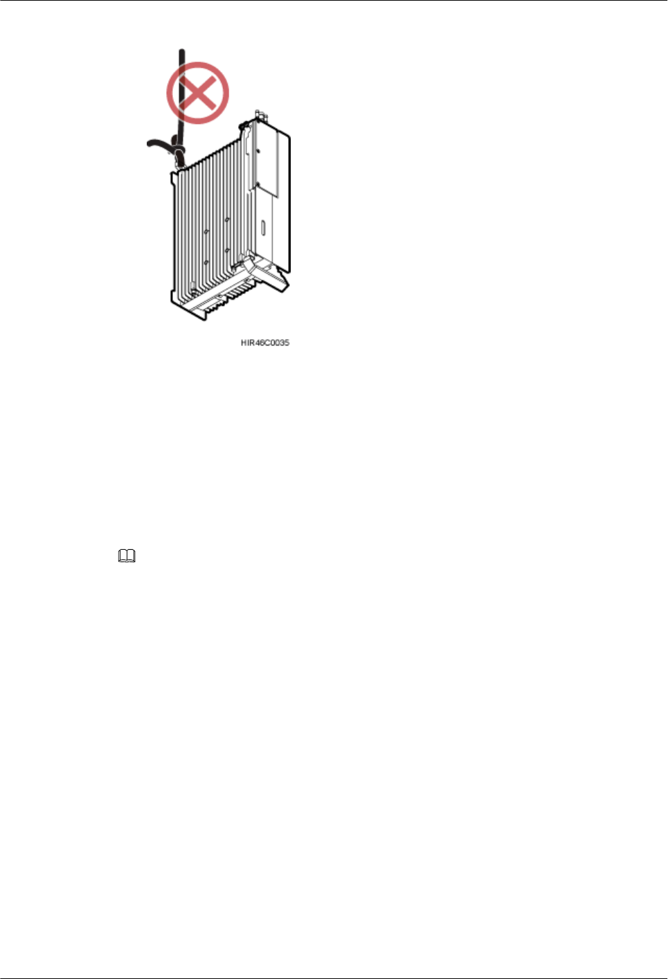
Figure 7-5 Incorrect binding method
3. Installation engineer B pulls the lifting sling downwards, and installation engineer C pulls
the traction sling outwards to protect the RRU from colliding with the tower.
Step 2 Installation engineer A catches the RRU, install the RRU on the main bracket, use an inner
hexagon screwdriver to tighten the captive screw into the hole of the attachment plate to 5 N·m
(44.25 lbf·in.) for connecting the attachment plate and the main bracket, see 8 Installing the
RRU.
Step 3 Remove the lifting sling and traction sling.
NOTE
The procedure for hoisting the RRU and mounting kits onto the tower is for your reference only.
----End
7.2 Hoisting Fiber Optic Cables onto a Tower
This section describes the procedure for hoisting fiber optic cables onto a tower and the
precautions that must be taken.
Context
Cabling requirements for power cables are met. For details, see 9.1 Cabling Requirements.
Procedure
Step 1 Hoist the fiber optic cables onto the tower, as shown in Figure 7-6.
RRU3260
Installation Guide 7 Hoisting an RRU and Related Cables onto a Tower
Issue () Huawei Proprietary and Confidential
Copyright © Huawei Technologies Co., Ltd.
46
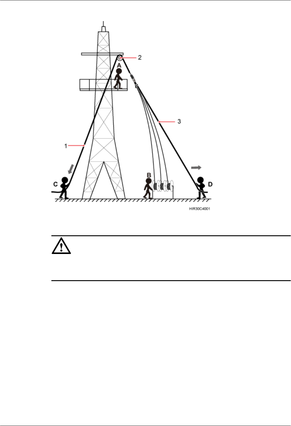
Figure 7-6 Hoisting fiber optic cables onto the tower
(1) Lifting sling (2) Fixed pulley (3) Traction sling
CAUTION
Before hoisting fiber optic cables onto the tower, connect the fiber optic cables to the RRU or
BBU based on the labels on both ends of the cables and determine the hoisting direction.
1. After climbing up to the tower, installation engineer A secures the fixed pulley to the tower
platform support and leads the lifting sling through the fixed pulley.
2. Installation engineer B places the fiber coiler for coiling fiber optic cables on the fiber
spools, and installation engineer D lead the lifting sling through the stretch sling of the fiber
optic cables and use the other sling as a traction sling to secure the cables 4 m (13.12 ft)
away from the lifting sling, as shown in Figure 7-7.
RRU3260
Installation Guide 7 Hoisting an RRU and Related Cables onto a Tower
Issue () Huawei Proprietary and Confidential
Copyright © Huawei Technologies Co., Ltd.
47
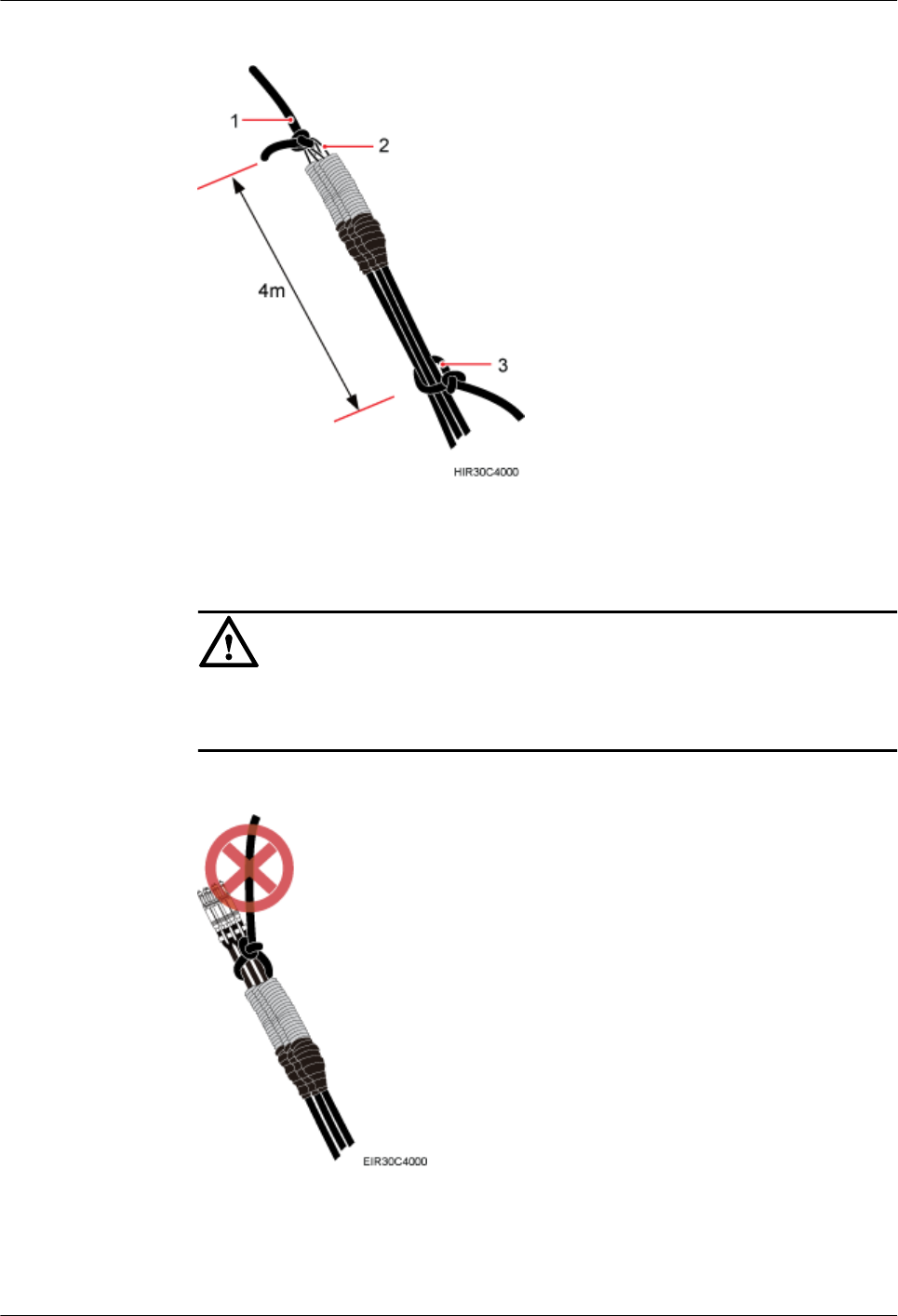
Figure 7-7 Binding fiber optic cables
(1) Lifting sling (2) Stretch sling (3) Traction sling
CAUTION
Do not remove the stretch sling and protection pipe or bind fiber optic cables using one
sling, as shown in Figure 7-8.
Figure 7-8 Incorrect binding method
3. Installation engineer B rotates the fiber spools at the speed of 5 m (16.4 ft) to 15 m (49.21
ft) per minute to coil the fiber optic cables.
RRU3260
Installation Guide 7 Hoisting an RRU and Related Cables onto a Tower
Issue () Huawei Proprietary and Confidential
Copyright © Huawei Technologies Co., Ltd.
48

4. Installation engineer C pulls the lifting sling downwards, and installation engineer D pulls
the traction sling outwards to protect the fiber optic cables from colliding with the tower.
Step 2 Secure the fiber optic cables to the tower vertically using cable clips.
Step 3 Remove the lifting sling, traction sling, and protection pipe.
NOTE
The procedure for hoisting the fiber optic cables onto the tower is for your reference only.
----End
7.3 Hoisting Power Cables onto a Tower
This section describes the procedure for hoisting power cables onto a tower and the precautions
that must be taken.
Context
Cabling requirements for power cables are met. For details, see 9.1 Cabling Requirements.
The procedure for adding a connector to the RRU power cable on the RRU side is done under
the tower.
Procedure
Step 1 Hoist the power cables onto the tower, as shown in Figure 7-9.
RRU3260
Installation Guide 7 Hoisting an RRU and Related Cables onto a Tower
Issue () Huawei Proprietary and Confidential
Copyright © Huawei Technologies Co., Ltd.
49
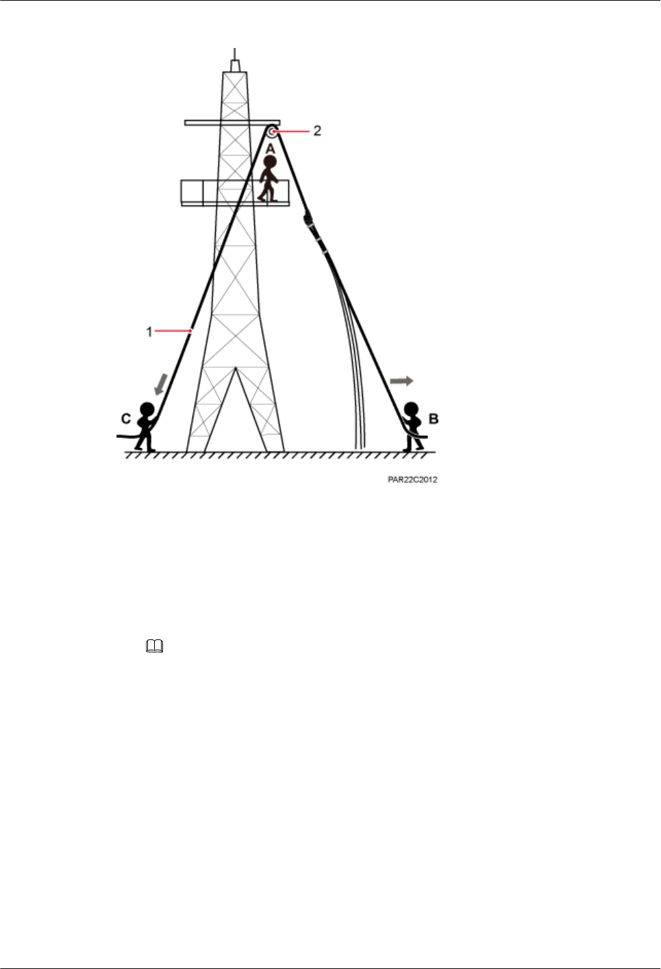
Figure 7-9 Hoisting power cables onto the tower
(1) Lifting sling (2) Fixed pulley
1. After climbing up to the tower, installation engineer A secures the fixed pulley to the tower
platform support and leads the lifting sling through the fixed pulley.
2. Installation engineer B secures three cable ties to the power cable connector, and then
secures the power cable to the lifting sling, as shown in Figure 7-10.
NOTE
The connector on the power cable in the figure is only an example. The actual connector may vary
according to the situation.
RRU3260
Installation Guide 7 Hoisting an RRU and Related Cables onto a Tower
Issue () Huawei Proprietary and Confidential
Copyright © Huawei Technologies Co., Ltd.
50
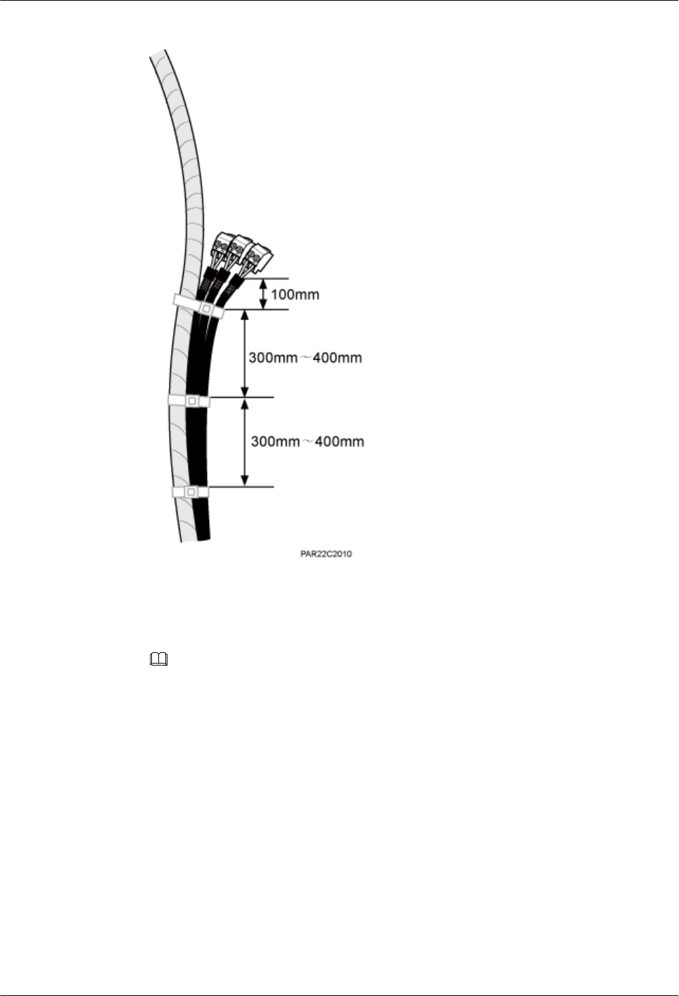
Figure 7-10 Binding cable ties
3. Installation engineer B wraps the power cable connector with a layer of PVC insulation
tape, as shown in Figure 7-11.
NOTE
Wrap the PVC insulation tape from 30 mm (1.18 in.) away from one end of the connector until it
reaches the other end of the connector. The total length of the wrapped connector is 100 mm (3.94
in.).
RRU3260
Installation Guide 7 Hoisting an RRU and Related Cables onto a Tower
Issue () Huawei Proprietary and Confidential
Copyright © Huawei Technologies Co., Ltd.
51
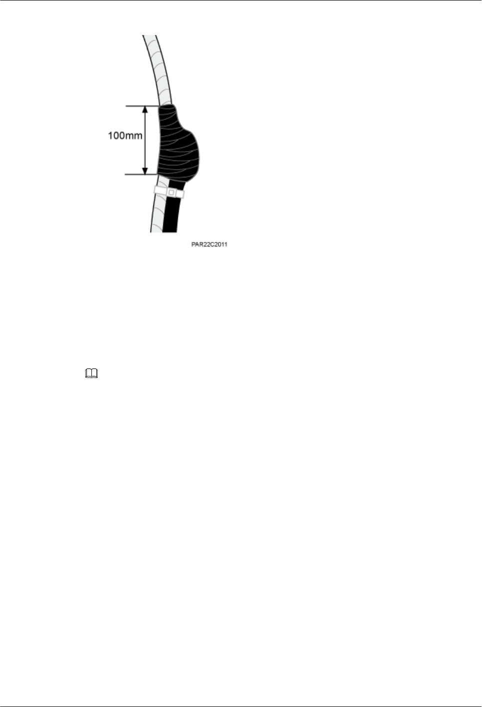
Figure 7-11 Wrapping the PVC insulation tape
4. Installation engineer C pulls the lifting sling downwards, and installation engineer B pulls
the other end of the lifting sling outwards to protect the power cables from colliding with
the tower.
Step 2 Secure the power cables to the tower vertically using cable clips.
Step 3 Remove the cable ties, PVC insulation tape, and lifting sling.
NOTE
The procedure for hoisting the power cables onto the tower is for your reference only.
----End
RRU3260
Installation Guide 7 Hoisting an RRU and Related Cables onto a Tower
Issue () Huawei Proprietary and Confidential
Copyright © Huawei Technologies Co., Ltd.
52

8 Installing the RRU
About This Chapter
This chapter describes the procedure for installing the RRU. The RRU can be installed on a pole,
U-steel, angle steel, wall, or an IFS06 . The procedure for installing the RRU varies depending
on installation options.
8.1 Mounting Kits for an RRU
This section describes the bracket assembly and the attachment plate for an RRU.
8.2 Installing the RRU on a Pole
One or more RRUs can be installed on a pole.
8.3 Installing the RRU on U-steel
This section describes the procedure and precautions for installing the RRU on U-steel. An RRU
can be installed on U-steel secured on the ground or a tower. Each piece of U-steel allows only
one RRU to be installed in standard or reverse mode.
8.4 Installing the RRU on Angle Steel
This section describes the procedure and precautions for installing the RRU on angle steel. An
RRU can be installed on angle steel secured on the ground or a tower. Each piece of angle steel
allows only one RRU to be installed in standard or reverse mode.
8.5 Installing the RRU on a Wall
This section describes the procedure and precautions for installing the RRU on a wall.
8.6 Installing an RRU on an IFS06
This section describes the procedure and precautions for installing an RRU on an IFS06.
RRU3260
Installation Guide 8 Installing the RRU
Issue () Huawei Proprietary and Confidential
Copyright © Huawei Technologies Co., Ltd.
53
8.1 Mounting Kits for an RRU
This section describes the bracket assembly and the attachment plate for an RRU.
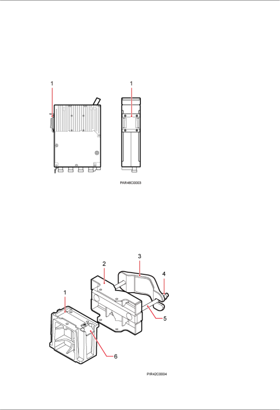
Figure 8-1 shows the front and rear of an RRU.
Figure 8-1 Front and side view of an RRU
(1) Attachment plate
Figure 8-2 shows the bracket assembly for an RRU.
Figure 8-2 12 L blade RRU mounting kit
(1) Main bracket (2) Pole installation
bracket
(3) Auxiliary bracket (4) Nut (5) Square-neck
bolt
(6) Hoist clamp on
the main bracket
RRU3260
Installation Guide 8 Installing the RRU
Issue () Huawei Proprietary and Confidential
Copyright © Huawei Technologies Co., Ltd.
54
8.2 Installing the RRU on a Pole
One or more RRUs can be installed on a pole.
8.2.1 Installing a Single RRU
This section describes the procedure and precautions for installing a single RRU on a pole.
Prerequisites
Before you install an RRU on a pole secured on a tower, the RRU and its mounting brackets are
hoisted onto the tower. For details, see 7.1 Hoisting an RRU onto a Tower.
The hoist clamp on the main bracket is secured properly.
CAUTION
lDo not stand the RRU upright because the RF ports cannot support the weight of the RRU.
lPlace a foam pad or cardboard under the RRU to protect the RRU housing from damage
during the installation.
Procedure
Step 1 Determine a position for installing the mounting brackets.
lIf the pole must be installed on a tower, determine a position for installing the mounting
brackets according to the instructions in 3.5.1 Clearance for a Single RRU.
lIf the pole must be installed on the ground, determine a position for installing the mounting
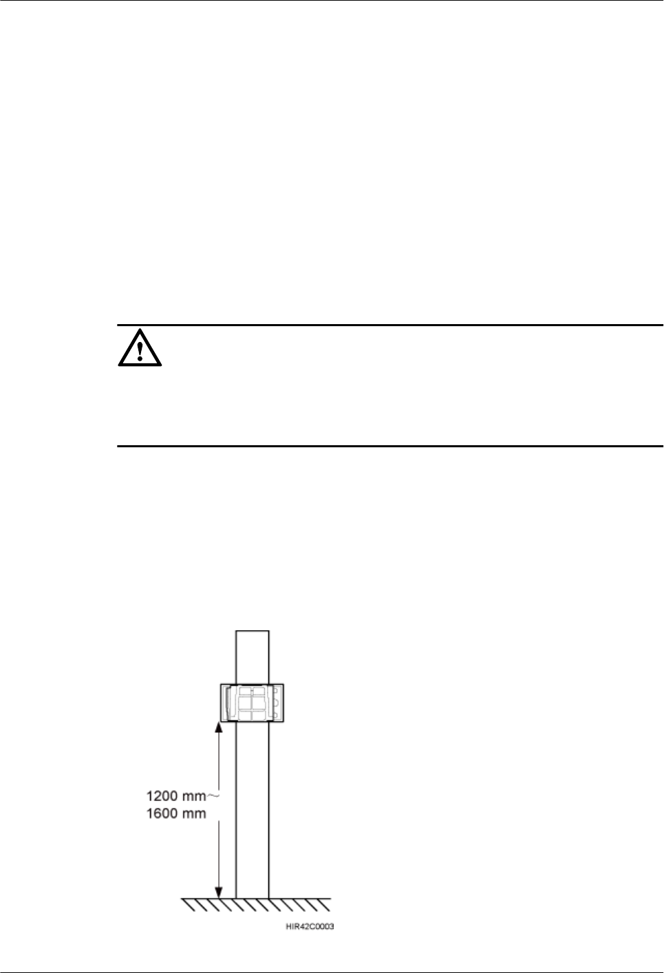
brackets according to Figure 8-3.
Figure 8-3 Distance between the mounting brackets and the ground
RRU3260
Installation Guide 8 Installing the RRU
Issue () Huawei Proprietary and Confidential
Copyright © Huawei Technologies Co., Ltd.
55
NOTE
It is recommended that the mounting brackets be installed at a height of 1200 mm (47.24 in.) to 1600
mm (62.99 in.) above the ground.
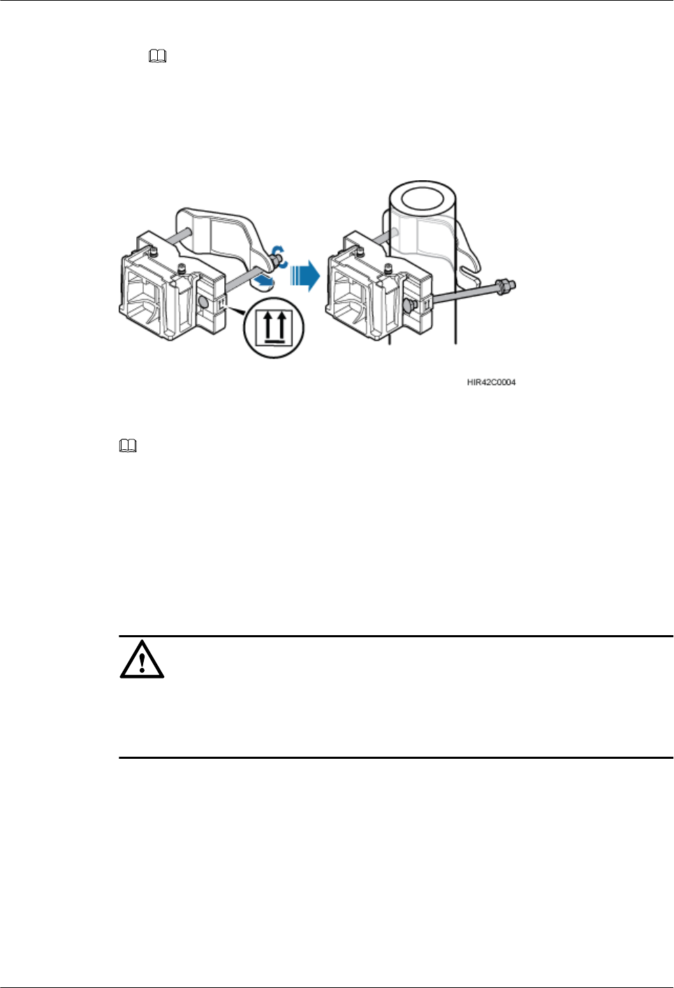
Step 2 Install the RRU mounting brackets, as shown in Figure 8-4.
Figure 8-4 Installing the RRU mounting brackets
NOTE
Verify that the arrows on the mounting brackets are pointing up.
1. Adjust the position of the nut and remove one end of the square-neck bolt from the slot on
the auxiliary bracket.
2. Slide the mounting brackets onto the pole horizontally and insert the square-neck bolt into
the slot.
Step 3 Use a 16 mm (0.63 in.) M10 torque wrench to tighten the nuts to 40 N·m (354.03 lbf·in.) so that
the mounting brackets are secured onto the pole, as shown in Figure 8-5.
CAUTION
Tighten the nuts on the two square-neck bolts alternatively. After the main and auxiliary brackets
are secured properly, measure the spacing between the brackets on both sides and ensure that
the spacing is the same on the two sides.
RRU3260
Installation Guide 8 Installing the RRU
Issue () Huawei Proprietary and Confidential
Copyright © Huawei Technologies Co., Ltd.
56
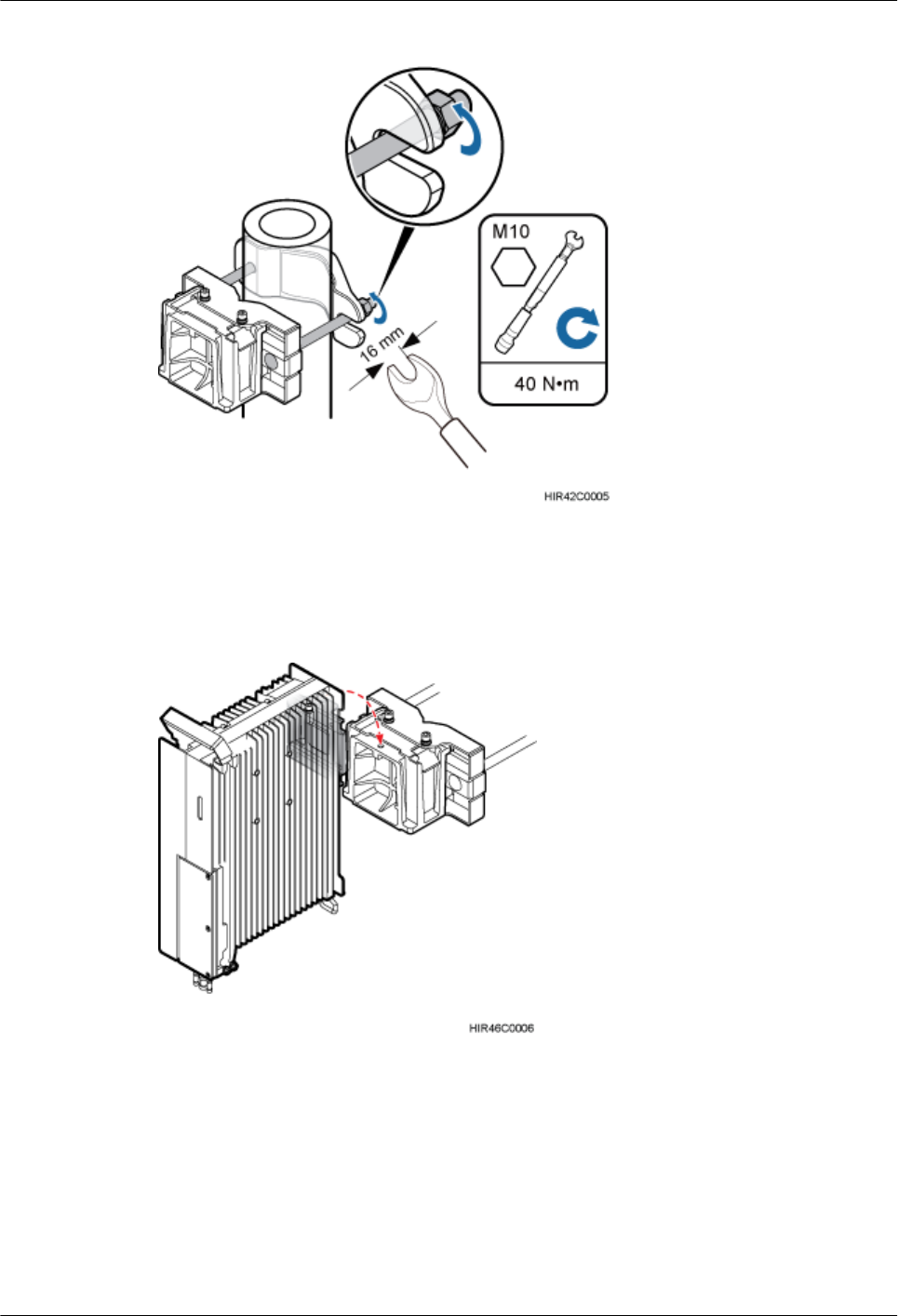
Figure 8-5 Securing the RRU mounting brackets
Step 4 Install the RRU onto the main bracket, as shown in Figure 8-6.
Figure 8-6 Installing the RRU onto the main bracket
Step 5 Use an inner hexagon torque screwdriver to tighten the captive screw into the holes on the top
of the attachment plate and main bracket to 5 N·m (44.25 lbf·in.) so that the attachment plate
and main bracket are firmly secured, as shown in Figure 8-7.
RRU3260
Installation Guide 8 Installing the RRU
Issue () Huawei Proprietary and Confidential
Copyright © Huawei Technologies Co., Ltd.
57
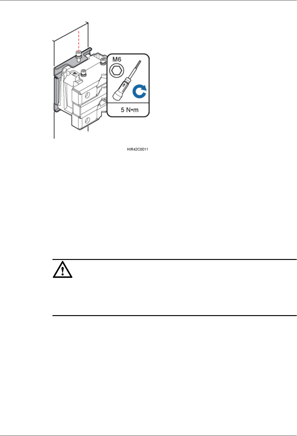
Figure 8-7 Securing the captive screw into the connection hole
----End
8.2.2 Installing Two RRUs
This section describes the procedure and precautions for installing two RRUs on a pole.
Prerequisites
The hoist clamp on the main bracket is secured properly.
CAUTION
lDo not stand the RRU upright because the RF ports cannot support the weight of the RRU.
lPlace a foam pad or cardboard under the RRU to protect the RRU housing from damage
during the installation.
Procedure
Step 1 Install the first RRU onto the main bracket, as shown in Figure 8-8. For details, see 8.2.1
Installing a Single RRU.
RRU3260
Installation Guide 8 Installing the RRU
Issue () Huawei Proprietary and Confidential
Copyright © Huawei Technologies Co., Ltd.
58
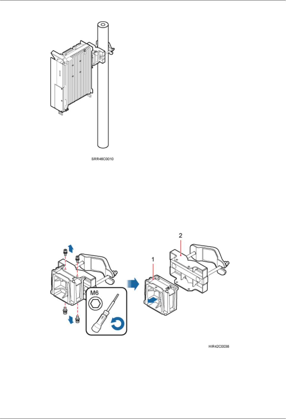
Figure 8-8 Installing the first RRU onto the main bracket
Step 2 Use an M6 inner hexagon screwdriver to remove the four inner hexagon screws from the second
set of mounting brackets, and remove the main bracket from the auxiliary bracket, as shown in
Figure 8-9.
Figure 8-9 Removing the RRU main bracket
(1) Main bracket (2) Pole installation bracket
Step 3 Install the removed main bracket on one side of the first main bracket, as shown in Figure
8-10.
RRU3260
Installation Guide 8 Installing the RRU
Issue () Huawei Proprietary and Confidential
Copyright © Huawei Technologies Co., Ltd.
59
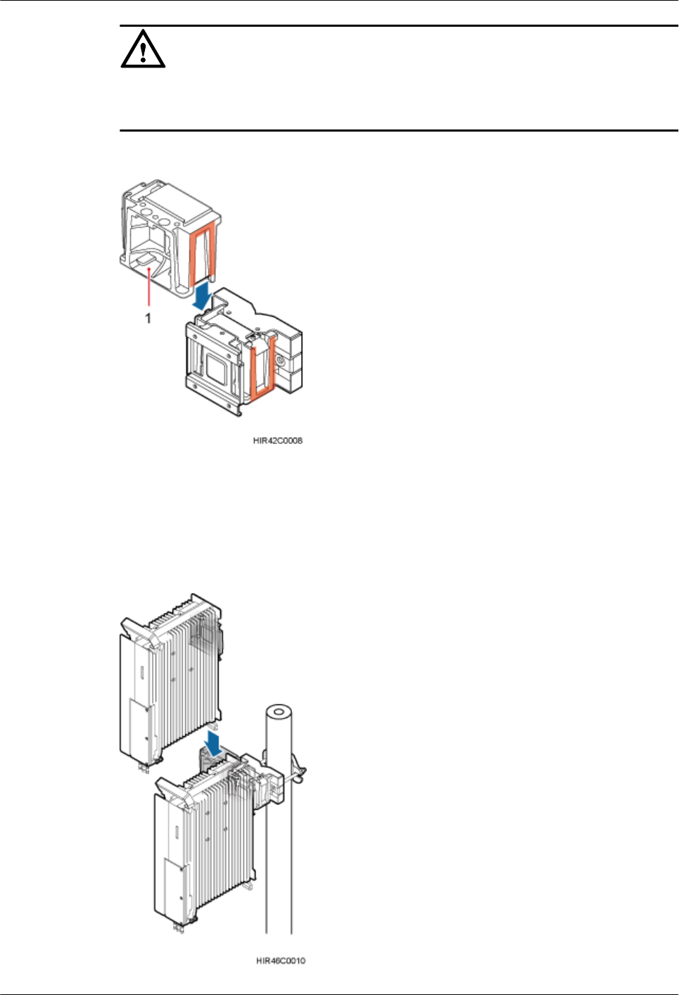
CAUTION
The second main bracket must be installed with the opening ends of U-shaped slots on both sides
facing downwards.
Figure 8-10 Installing the second main bracket
(1) Removed main bracket
Step 4 Install the second RRU onto the main bracket, as shown in Figure 8-11.
Figure 8-11 Installing the second RRU onto the main bracket
RRU3260
Installation Guide 8 Installing the RRU
Issue () Huawei Proprietary and Confidential
Copyright © Huawei Technologies Co., Ltd.
60
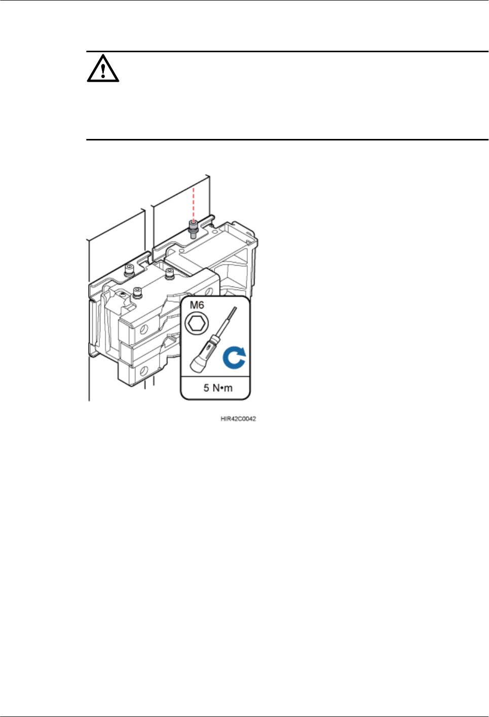
CAUTION
After installing each RRU on its main bracket, use an inner hexagon torque screwdriver to tighten
the captive screw into the holes of the attachment plate and main bracket to 5 N·m (44.25 lbf·in.)
so that the attachment plate and main bracket are firmly secured, as shown in Figure 8-12.
Figure 8-12 Securing the captive screw into the connection hole
Step 5 Install the metal sheet for neighboring RRUs, as shown in Figure 8-13.
RRU3260
Installation Guide 8 Installing the RRU
Issue () Huawei Proprietary and Confidential
Copyright © Huawei Technologies Co., Ltd.
61
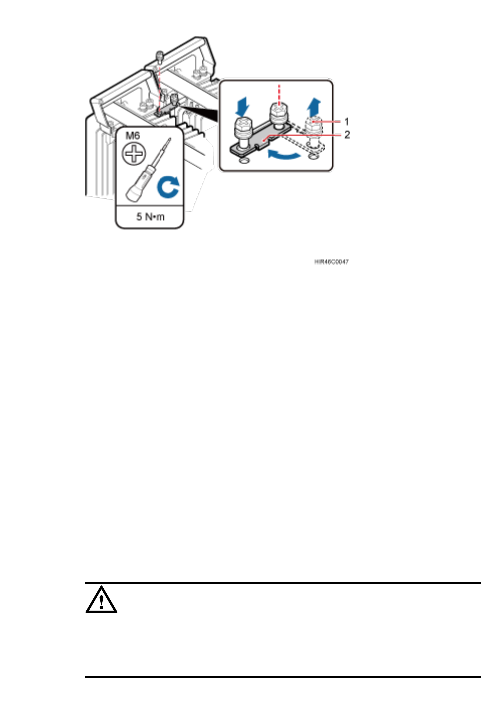
Figure 8-13 Installing the metal sheet
(1) Screw (2) Metal sheet
1. Use an M6 Phillips screwdriver to loosen the screw on the metal sheet farther from the
handle of the first RRU and remove the screw.
2. Use an M6 Phillips screwdriver to loosen the screw on the metal sheet closer to handle of
the first RRU. Then rotate the metal sheet to align the vacant hole in the metal sheet with
a hole on the top of the second RRU.
3. Insert the removed screw into the hole on the top of the second RRU and use an M6 torque
screwdriver to tighten the screw to 5 N·m (44.25 lbf·in.).
----End
8.2.3 Installing Three or More RRUs
The section describes the procedure and precautions for installing three or more RRUs on a pole.
Prerequisites
The hoist clamp on the main bracket is secured properly.
CAUTION
lDo not stand the RRU upright because the RF ports cannot support the weight of the RRU.
lPlace a foam pad or cardboard under the RRU to protect the RRU housing from damage
during the installation.
RRU3260
Installation Guide 8 Installing the RRU
Issue () Huawei Proprietary and Confidential
Copyright © Huawei Technologies Co., Ltd.
62
Context
A pole supports the installation of three, four, or six RRUs. The procedures for installing them
are the same. Following is the procedure of installing four RRUs on a pole.
Procedure
Step 1 Install the two RRUs, as shown in Figure 8-14. For details, see 8.2.2 Installing Two RRUs.
Figure 8-14 Two RRUs installed on a pole
Step 2 Use an M6 inner hexagon screwdriver to remove the four inner hexagon screws from the second
set of mounting brackets, and remove the main bracket from the auxiliary bracket, as shown in
Figure 8-15.
RRU3260
Installation Guide 8 Installing the RRU
Issue () Huawei Proprietary and Confidential
Copyright © Huawei Technologies Co., Ltd.
63
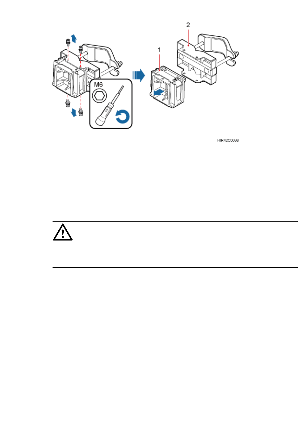
Figure 8-15 Removing the RRU main bracket
(1) Main bracket (2) Pole installation bracket
Step 3 Install the third main bracket and install the third RRU onto the third main bracket. Then use an
inner hexagon torque screwdriver to tighten the captive screw into the connection holes on the
top of the attachment plate and main bracket for the RRU, with a torque of 5 N·m (44.25 lbf·in.),
as shown in Figure 8-16.
CAUTION
The third main bracket must be installed with the opening ends of U-shaped slots on both sides
facing downwards.
RRU3260
Installation Guide 8 Installing the RRU
Issue () Huawei Proprietary and Confidential
Copyright © Huawei Technologies Co., Ltd.
64
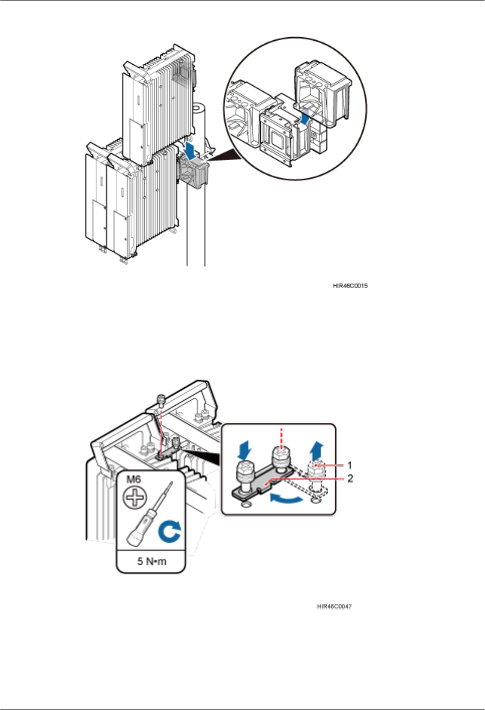
Figure 8-16 Installing the third RRU onto the third main bracket
Step 4 Install the metal sheet for neighboring RRUs, as shown in Figure 8-17.
Figure 8-17 Installing the metal sheet
(1) Screw (2) Metal sheet
1. Use an M6 Phillips screwdriver to loosen the screw on the metal sheet farther from the
handle of the first RRU and remove the screw.
RRU3260
Installation Guide 8 Installing the RRU
Issue () Huawei Proprietary and Confidential
Copyright © Huawei Technologies Co., Ltd.
65
2. Use an M6 Phillips screwdriver to loosen the screw on the metal sheet closer to handle of
the first RRU. Then rotate the metal sheet to align the vacant hole in the metal sheet with
a hole on the top of the second RRU.
3. Insert the removed screw into the hole on the top of the second RRU and use an M6 torque
screwdriver to tighten the screw to 5 N·m (44.25 lbf·in.).
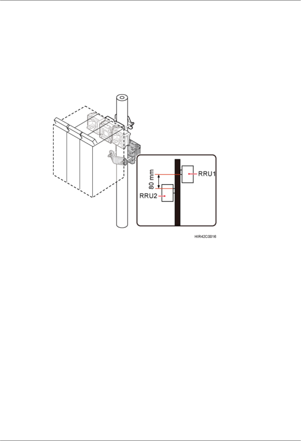
Step 5 At a position 80 mm (3.15 in.) above or below the first set of RRU mounting brackets, install
the second set of RRU mounting brackets, as shown in Figure 8-18.
Figure 8-18 Installing the second set of RRU mounting brackets
Step 6 Install the fourth RRU onto the fourth main bracket, use an inner hexagon torque screwdriver
to tighten the captive screw into the holes of the attachment plate and main bracket to 5 N·m
(44.25 lbf·in.) so that the attachment plate and main bracket are firmly secured, as shown in
Figure 8-19.
RRU3260
Installation Guide 8 Installing the RRU
Issue () Huawei Proprietary and Confidential
Copyright © Huawei Technologies Co., Ltd.
66
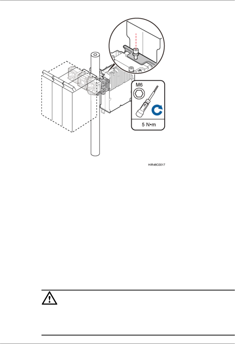
Figure 8-19 Installing the fourth RRU onto the fourth main bracket
----End
8.3 Installing the RRU on U-steel
This section describes the procedure and precautions for installing the RRU on U-steel. An RRU
can be installed on U-steel secured on the ground or a tower. Each piece of U-steel allows only
one RRU to be installed in standard or reverse mode.
Prerequisites
Before you install an RRU on U-steel secured on a tower, the RRU and its mounting brackets
are hoisted onto the tower. For details, see 7.1 Hoisting an RRU onto a Tower.
The hoist clamp on the main bracket is secured properly.
CAUTION
lDo not stand the RRU upright because the RF ports cannot support the weight of the RRU.
lPlace a foam pad or cardboard under the RRU to protect the RRU housing from damage
during the installation.
RRU3260
Installation Guide 8 Installing the RRU
Issue () Huawei Proprietary and Confidential
Copyright © Huawei Technologies Co., Ltd.
67
Context
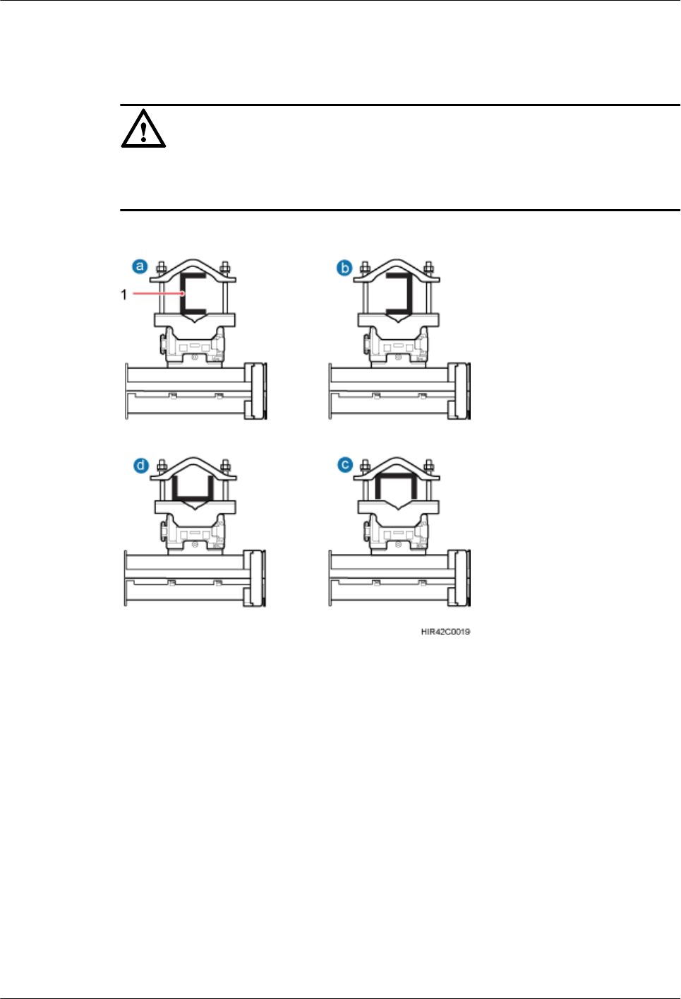
Figure 8-20 shows the top view of the RRU installed on U-steel.
CAUTION
When the width of the narrower edges of the U-steel is less than 40 mm (1.57 in.), only the a
and b modes are supported.
Figure 8-20 Top view of the RRU
(1) U-steel
Procedure
Step 1 Determine a position for installing the mounting brackets.
lIf the RRU must be installed on U-steel secured on a tower, see 3.5.1 Clearance for a
Single RRU to determine a position.
lIf the RRU must be installed on U-steel secured on the ground, see Figure 8-21 to determine
a position.
RRU3260
Installation Guide 8 Installing the RRU
Issue () Huawei Proprietary and Confidential
Copyright © Huawei Technologies Co., Ltd.
68
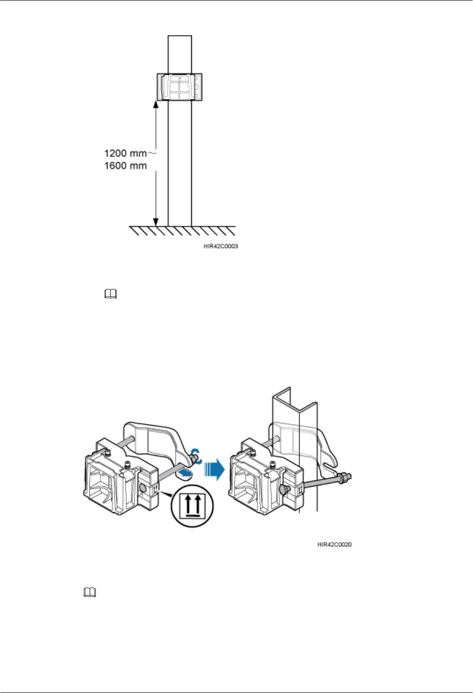
Figure 8-21 Distance between the mounting brackets and the ground
NOTE
It is recommended that the mounting brackets be installed at a height of 1200 mm (47.24 in.) to 1600
mm (62.99 in.) above the ground.
Step 2 Install the RRU mounting brackets, as shown in Figure 8-22.
Figure 8-22 Installing the RRU mounting brackets
NOTE
Verify that the arrows on the mounting brackets are pointing up.
1. Adjust the position of the nut and remove one end of the square-neck bolt from the slot on
the auxiliary bracket.
2. Slide the mounting brackets onto the U-steel horizontally and insert the square-neck bolt
into the slot.
RRU3260
Installation Guide 8 Installing the RRU
Issue () Huawei Proprietary and Confidential
Copyright © Huawei Technologies Co., Ltd.
69
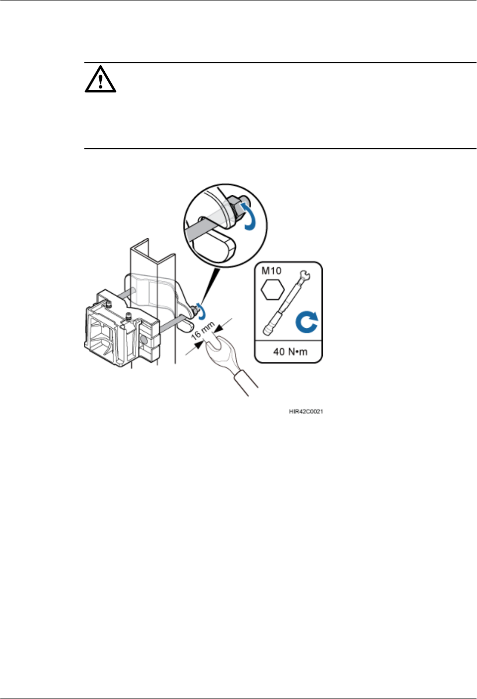
Step 3 Use a 16 mm (0.67 in.) M10 torque wrench to tighten the nuts to 40 N·m (354.03 lbf·in.) so that
the mounting brackets are secured onto the U-steel, as shown in Figure 8-23.
CAUTION
Tighten the nuts on the two square-neck bolts alternatively. After the main and auxiliary brackets
are secured properly, measure the spacing between the brackets on both sides and ensure that
the spacing is the same on the two sides.
Figure 8-23 Securing the RRU mounting brackets
Step 4 Use an inner hexagon screwdriver to remove the attachment plate from one side of the RRU,
reinstall the attachment plate onto the rear of the RRU, and tighten the four stainless screws to
5 N·m (44.25 lbf·in.), as shown in Figure 8-24.
RRU3260
Installation Guide 8 Installing the RRU
Issue () Huawei Proprietary and Confidential
Copyright © Huawei Technologies Co., Ltd.
70
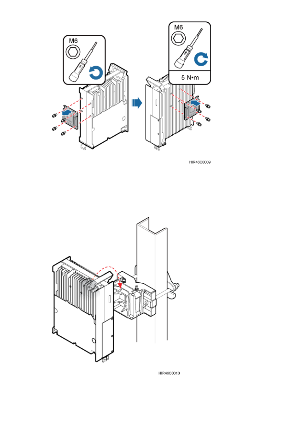
Figure 8-24 Installing the attachment plate onto the rear of the RRU
Step 5 Install the RRU onto the main bracket, as shown in Figure 8-25.
Figure 8-25 Installing the RRU onto the main bracket
Step 6 Use an inner hexagon screwdriver to tighten the captive screw into the holes on the top of the
attachment plate and main bracket to 5 N·m (44.25 lbf·in.) so that the attachment plate and main
bracket are firmly secured, as shown in Figure 8-26.
RRU3260
Installation Guide 8 Installing the RRU
Issue () Huawei Proprietary and Confidential
Copyright © Huawei Technologies Co., Ltd.
71
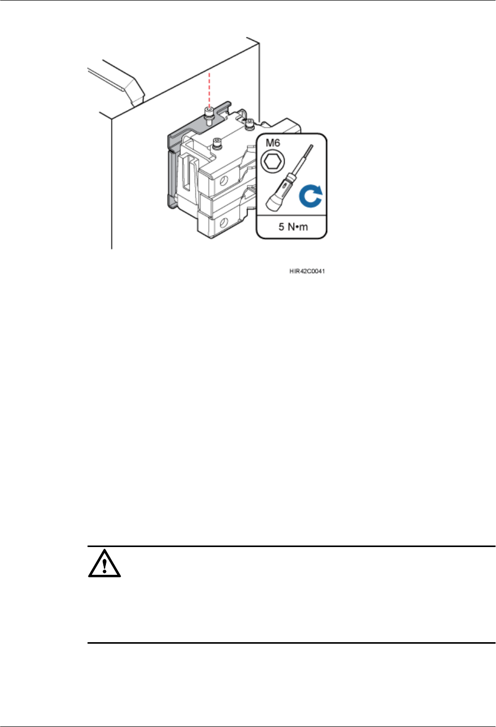
Figure 8-26 Securing the captive screw into the connection hole
----End
8.4 Installing the RRU on Angle Steel
This section describes the procedure and precautions for installing the RRU on angle steel. An
RRU can be installed on angle steel secured on the ground or a tower. Each piece of angle steel
allows only one RRU to be installed in standard or reverse mode.
Prerequisites
Before you install an RRU on angle steel secured on a tower, the RRU and its mounting brackets
are hoisted onto the tower. For details, see 7.1 Hoisting an RRU onto a Tower.
The hoist clamp on the main bracket is secured properly.
CAUTION
lDo not stand the RRU upright because the RF ports cannot support the weight of the RRU.
lPlace a foam pad or cardboard under the RRU to protect the RRU housing from damage
during the installation.
Context
Figure 8-27 shows the top view of the RRU installed on angle steel.
RRU3260
Installation Guide 8 Installing the RRU
Issue () Huawei Proprietary and Confidential
Copyright © Huawei Technologies Co., Ltd.
72
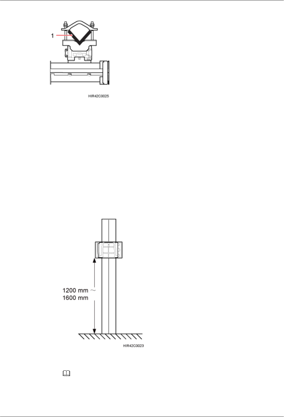
Figure 8-27 Top view of the RRU
(1) Angle steel
Procedure
Step 1 Determine a position for installing the mounting brackets.
lIf the RRU must be installed on angle steel secured on a tower, see 3.5.1 Clearance for a
Single RRU to determine a position.
lIf the RRU must be installed on angle steel secured on the ground, see Figure 8-28 to
determine a position.
Figure 8-28 Distance between the mounting brackets and the ground
NOTE
It is recommended that the mounting brackets be installed at a height of 1200 mm (47.24 in.) to 1600
mm (62.99 in.) above the ground.
Step 2 Install the RRU mounting brackets, as shown in Figure 8-29.
RRU3260
Installation Guide 8 Installing the RRU
Issue () Huawei Proprietary and Confidential
Copyright © Huawei Technologies Co., Ltd.
73
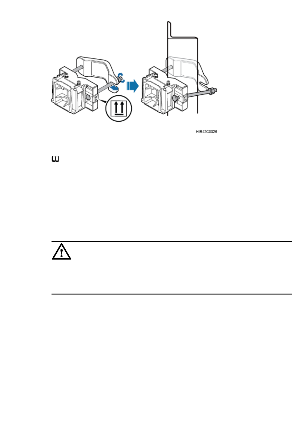
Figure 8-29 Installing the RRU mounting brackets
NOTE
Verify that the arrows on the mounting brackets are pointing up.
1. Adjust the position of the nut and remove one end of the square-neck bolt from the slot on
the auxiliary bracket.
2. Slide the mounting brackets onto the angle steel horizontally and insert the square-neck
bolt into the slot.
Step 3 Use a 16 mm (0.67 in.) M10 torque wrench to tighten the nuts to 40 N·m (354.03 lbf·in.) so that
the mounting brackets are secured onto the angle steel, as shown in Figure 8-30.
CAUTION
Tighten the nuts on the two square-neck bolts alternatively. After the main and auxiliary brackets
are secured properly, measure the spacing between the brackets on both sides and ensure that
the spacing is the same on the two sides.
RRU3260
Installation Guide 8 Installing the RRU
Issue () Huawei Proprietary and Confidential
Copyright © Huawei Technologies Co., Ltd.
74
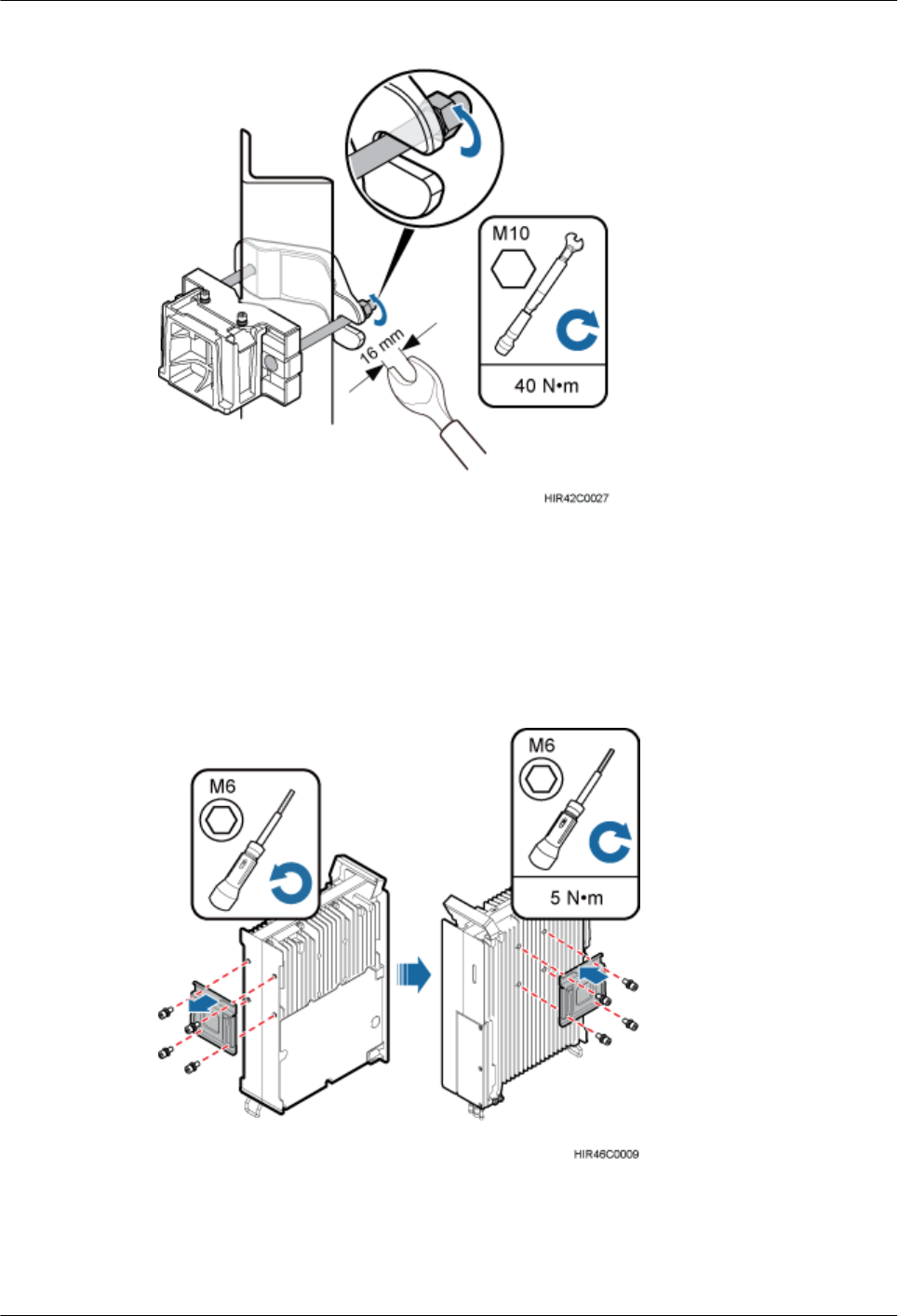
Figure 8-30 Securing the RRU mounting brackets
Step 4 Use an inner hexagon screwdriver to remove the attachment plate from one side of the RRU,
reinstall the attachment plate onto the rear of the RRU, and tighten the four stainless screws to
5 N·m (44.25 lbf·in.), as shown in Figure 8-31.
Figure 8-31 Installing the attachment plate onto the rear of the RRU
Step 5 Install the RRU onto the main bracket, as shown in Figure 8-32.
RRU3260
Installation Guide 8 Installing the RRU
Issue () Huawei Proprietary and Confidential
Copyright © Huawei Technologies Co., Ltd.
75
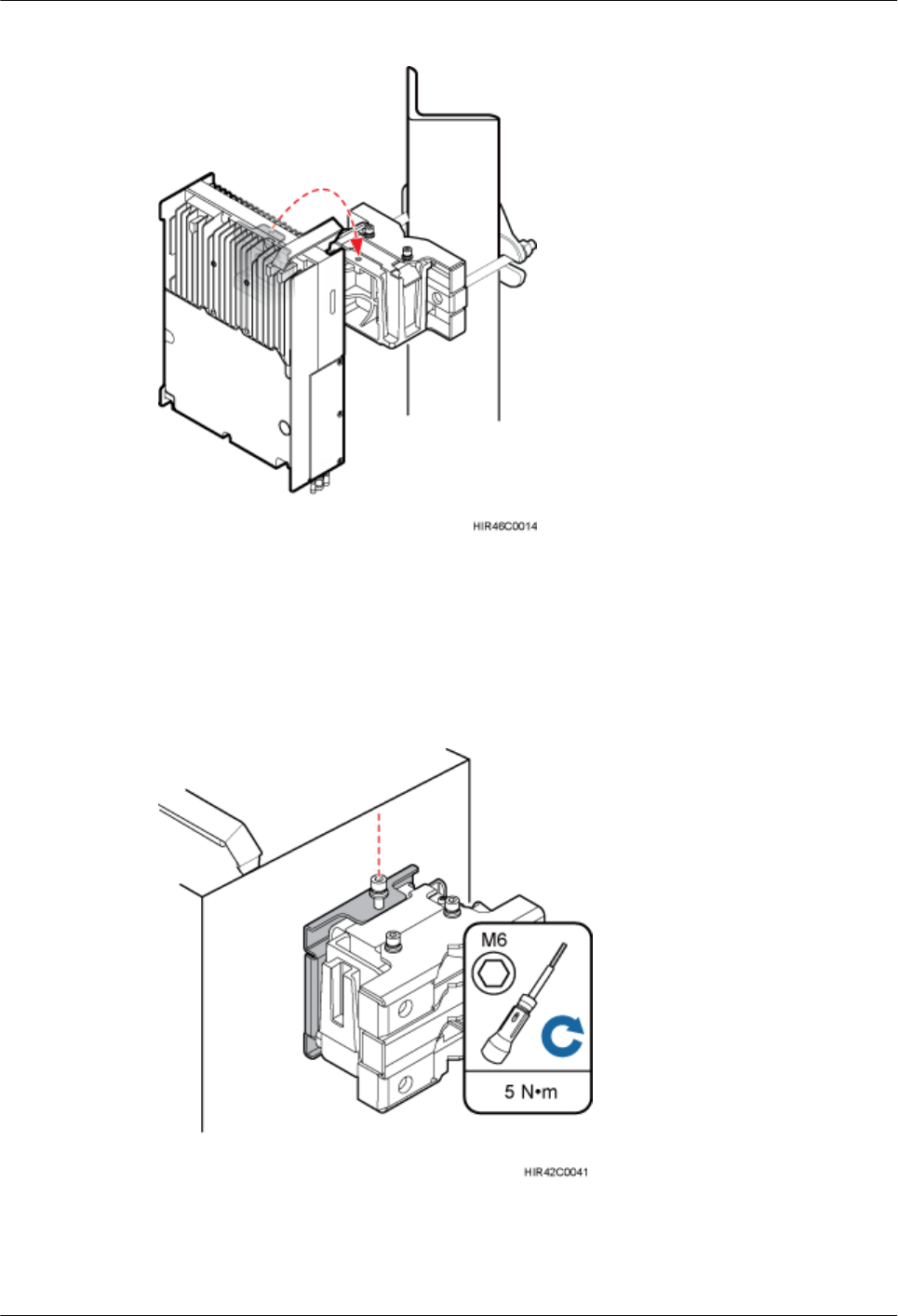
Figure 8-32 Installing the RRU onto the main bracket
Step 6 Use an inner hexagon screwdriver to tighten the captive screw into the holes on the top of the
attachment plate and main bracket to 5 N·m (44.25 lbf·in.) so that the attachment plate and main
bracket are firmly secured, as shown in Figure 8-33.
Figure 8-33 Securing the captive screw into the connection hole
----End
RRU3260
Installation Guide 8 Installing the RRU
Issue () Huawei Proprietary and Confidential
Copyright © Huawei Technologies Co., Ltd.
76
8.5 Installing the RRU on a Wall
This section describes the procedure and precautions for installing the RRU on a wall.
Prerequisites
The hoist clamp on the main bracket is secured properly.
CAUTION
lDo not stand the RRU upright because the RF ports cannot support the weight of the RRU.
lPlace a foam pad or cardboard under the RRU to protect the RRU housing from damage
during the installation.
Context
The wall on which RRUs are installed must meet the following requirements:
lWhen a single RRU is installed, the wall must be capable of bearing at least four times the
weight of the RRU.
lExpansion anchor bolts must be tightened to 30 N·m (265.52 lbf·in.) so that the bolts stay
secured without damaging the wall.
Procedure
Step 1 Disassemble the RRU mounting brackets, as shown in Figure 8-34.
RRU3260
Installation Guide 8 Installing the RRU
Issue () Huawei Proprietary and Confidential
Copyright © Huawei Technologies Co., Ltd.
77
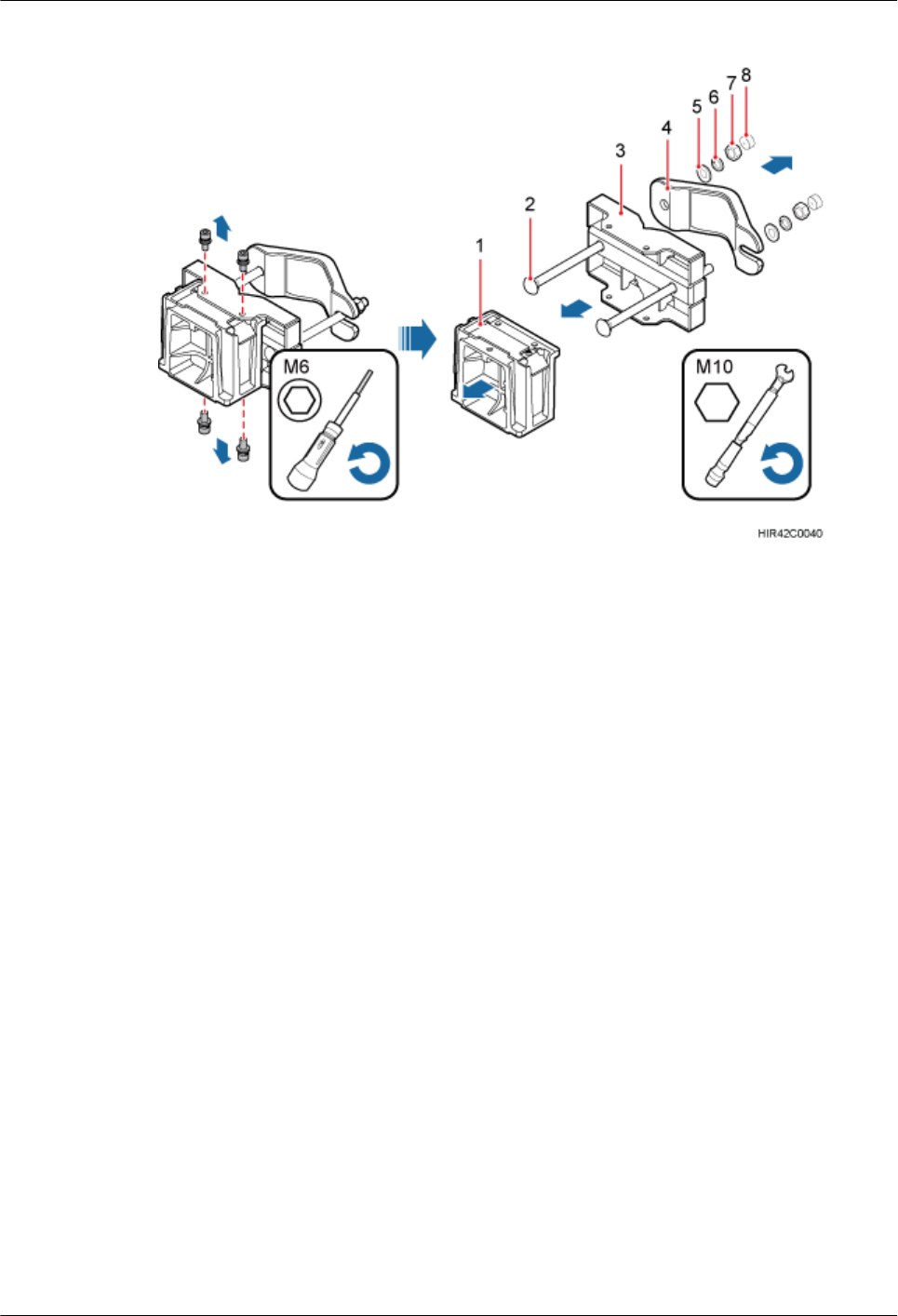
Figure 8-34 Disassembling the mounting brackets
(1) Main bracket (2) Square-neck bolt (3) Pole installation bracket (4) Auxiliary bracket
(5) Flat washer (6) Spring washer (7) Nut (8) Plastic cap
1. Use an M6 inner hexagon torque screwdriver to remove the four inner hexagon screws on
the pole installation bracket, and remove the main bracket from the pole installation bracket.
2. Use an M10 torque wrench to loosen the nuts on the two square-neck bolts, and remove
the plastic cap, nuts, spring washers, flat washers, square-neck bolts, and pole installation
bracket from the auxiliary bracket.
Step 2 Place the pole installation bracket against the installation position, use a level to verify that the
pole installation bracket is placed horizontally, and then mark anchor points with a marker, as
shown in Figure 8-35.
RRU3260
Installation Guide 8 Installing the RRU
Issue () Huawei Proprietary and Confidential
Copyright © Huawei Technologies Co., Ltd.
78
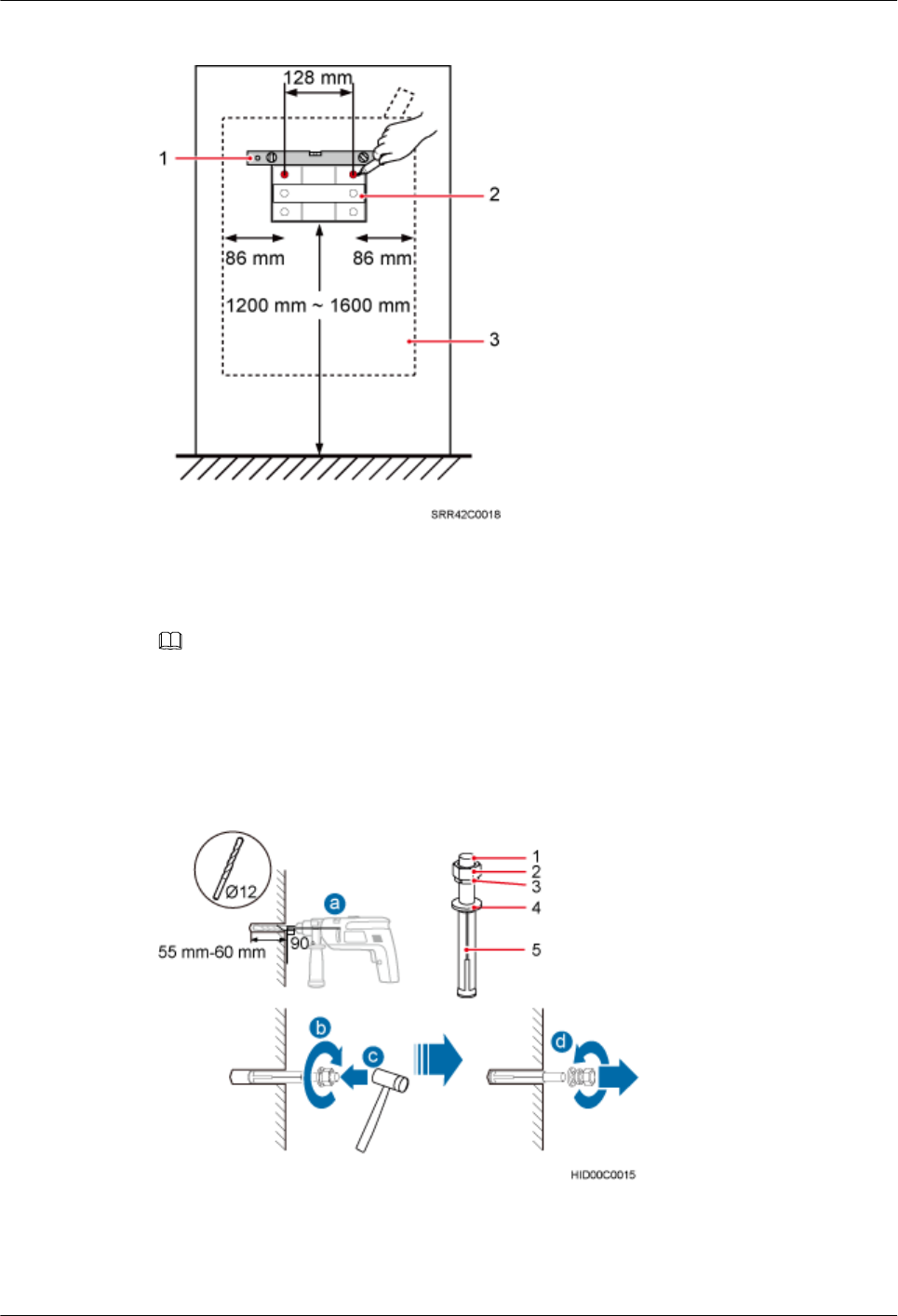
Figure 8-35 Marking anchor points
(1) Level (2) Pole installation bracket (3) RRU
NOTE
It is recommended that the pole installation bracket be installed at a height of 1200 mm (47.24 in.) to 1600
mm (62.99 in.) above the ground.
Step 3 Drill holes at the anchor points, and then insert expansion anchor bolt assemblies, as shown in
Figure 8-36.
Figure 8-36 Drilling a hole and inserting expansion anchor bolt assemblies
(1) M10x80 bolt (2) Nut (3) Spring washer (4) Flat washer (5) Expansion tube
RRU3260
Installation Guide 8 Installing the RRU
Issue () Huawei Proprietary and Confidential
Copyright © Huawei Technologies Co., Ltd.
79
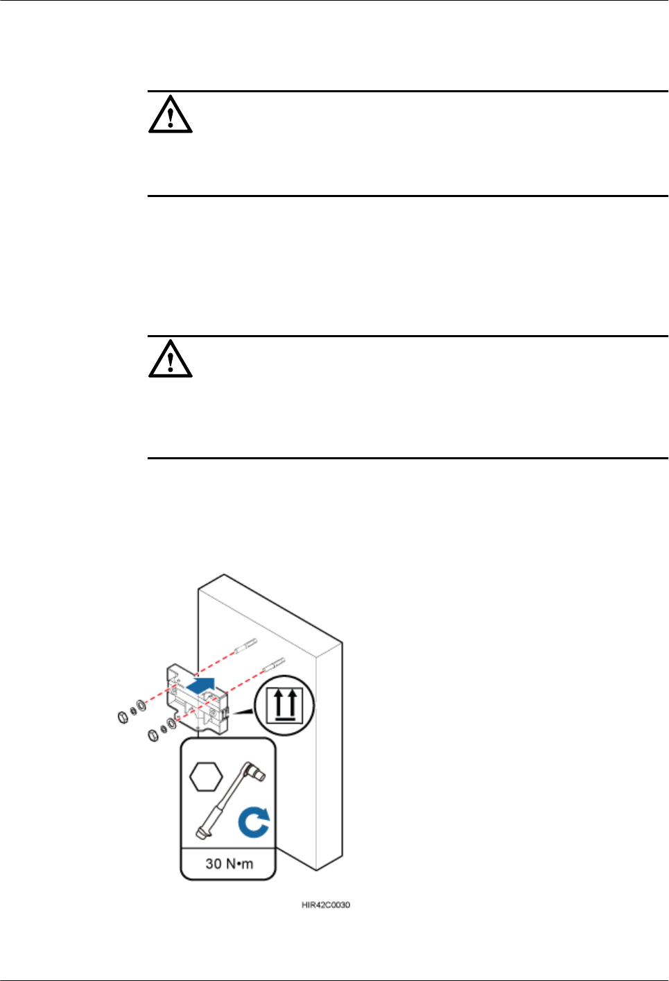
1. Use a hammer drill with a Ф12 bit to drill holes vertically at the marked anchor points.
Ensure that the depth of each hole ranges from 55 mm (2.17 in.) to 60 mm (2.36 in.).
CAUTION
Take proper safety measures to protect your eyes and respiratory tract against the dust
before drilling holes.
2. Tighten the expansion anchor bolts slightly and place one vertically into each hole.
3. Use a rubber mallet to pound the expansion anchor bolt until it goes all the way into the
hole.
4. Tighten and then loosen the expansion bolt, and remove the M10 bolt, spring washer, and
flat washer in sequence.
CAUTION
After dismantling an expansion anchor bolt, ensure that the top of the expansion tube is on
the same level as the wall. Otherwise, the device cannot be installed on the wall evenly and
securely.
Step 4 Install the pole installation bracket on the expansion anchor bolts, place the flat washers, spring
washers, and nuts through the expansion anchor bolts in sequence, and then use a 16 mm (0.63
in.) torque socket to tighten the nuts to 30 N·m (265.52 lbf·in.), as shown in Figure 8-37.
Figure 8-37 Installing the pole installation bracket on the expansion anchor bolts
RRU3260
Installation Guide 8 Installing the RRU
Issue () Huawei Proprietary and Confidential
Copyright © Huawei Technologies Co., Ltd.
80
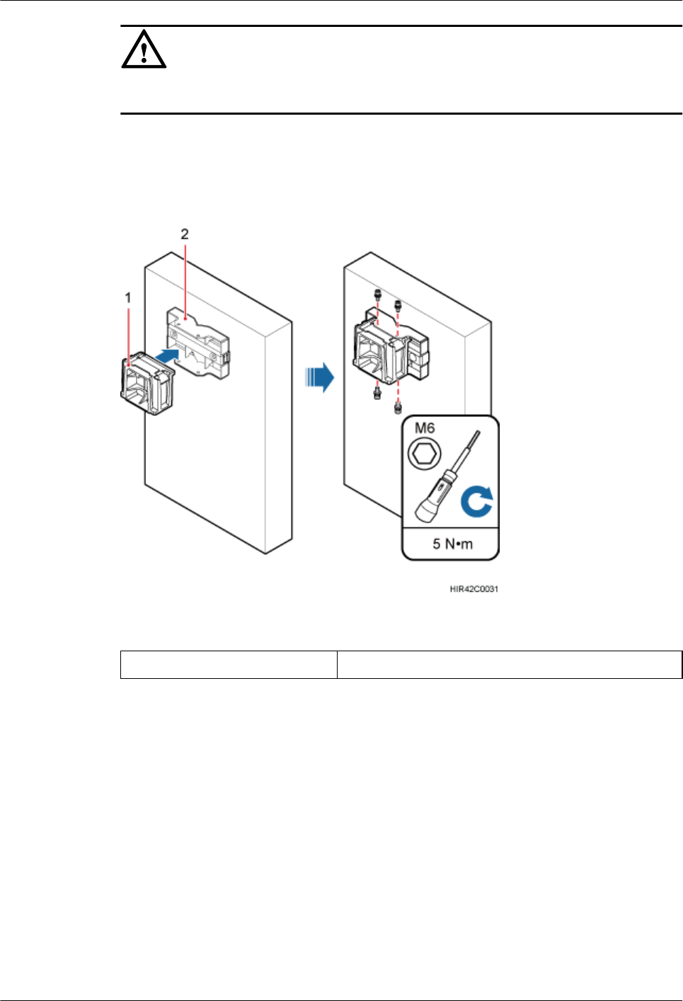
CAUTION
Verify that the arrows on the pole installation bracket are pointing up.
Step 5 Install the main bracket onto the pole installation bracket, and use an inner hexagon screwdriver
to tighten four M6x16 inner hexagon screws to 5 N·m (44.25 lbf·in.) so that the main bracket
and pole installation bracket are firmly secured, as shown in Figure 8-38.
Figure 8-38 Installing the main bracket
(1) Main bracket (2) Pole installation bracket
Step 6 Use an inner hexagon screwdriver to remove the attachment plate from one side of the RRU,
reinstall the attachment plate onto the rear of the RRU, and tighten the four stainless screws to
5 N·m (44.25 lbf·in.), as shown in Figure 8-39.
RRU3260
Installation Guide 8 Installing the RRU
Issue () Huawei Proprietary and Confidential
Copyright © Huawei Technologies Co., Ltd.
81
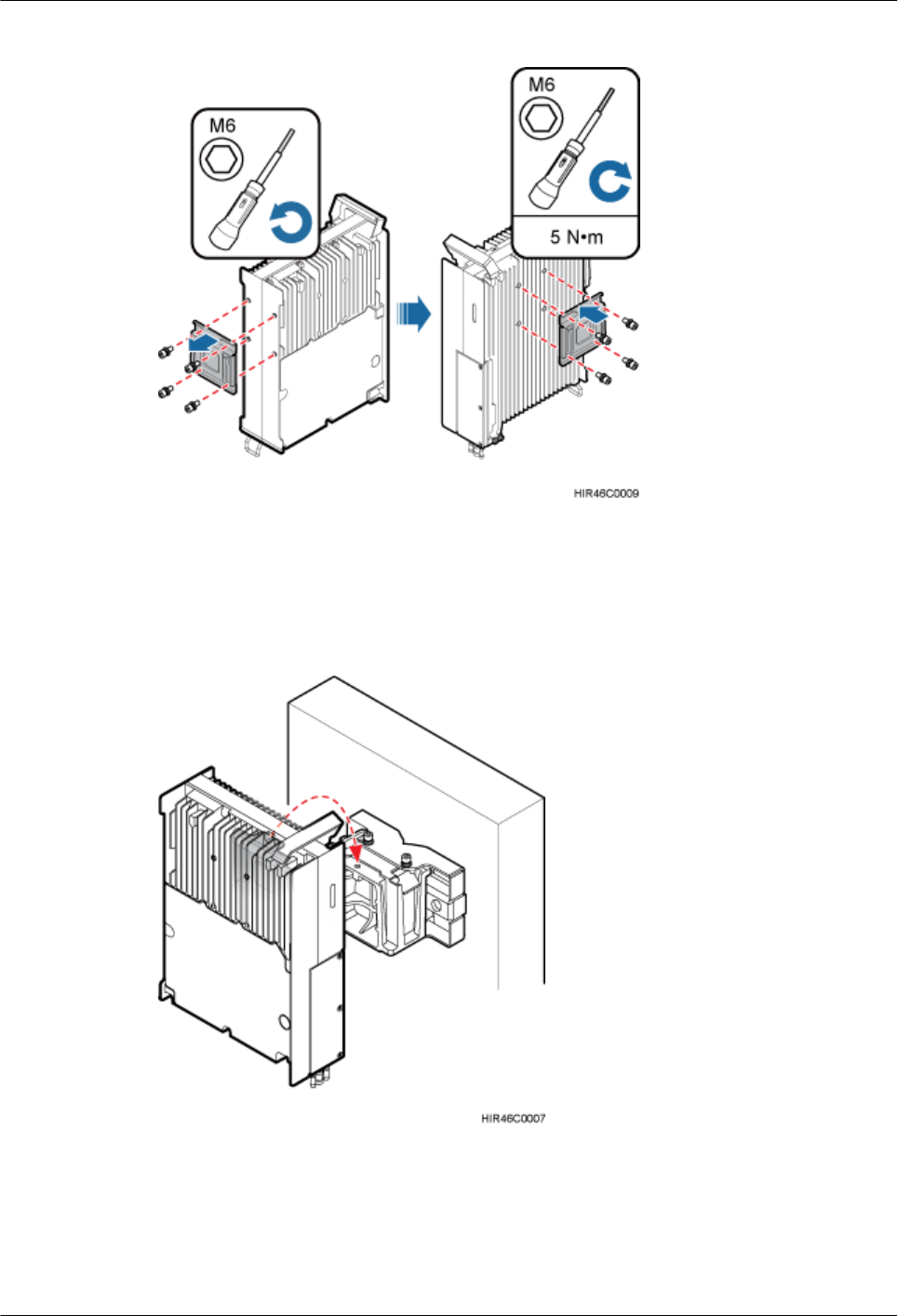
Figure 8-39 Installing the attachment plate onto the rear of the RRU
Step 7 Install the RRU onto the main bracket, as shown in Figure 8-40.
Figure 8-40 Installing the RRU onto the main bracket
Step 8 Use an inner hexagon screwdriver to tighten the captive screw into the holes on the top of the
attachment plate and main bracket to 5 N·m (44.25 lbf·in.) so that the attachment plate and main
bracket are firmly secured, as shown in Figure 8-41.
RRU3260
Installation Guide 8 Installing the RRU
Issue () Huawei Proprietary and Confidential
Copyright © Huawei Technologies Co., Ltd.
82
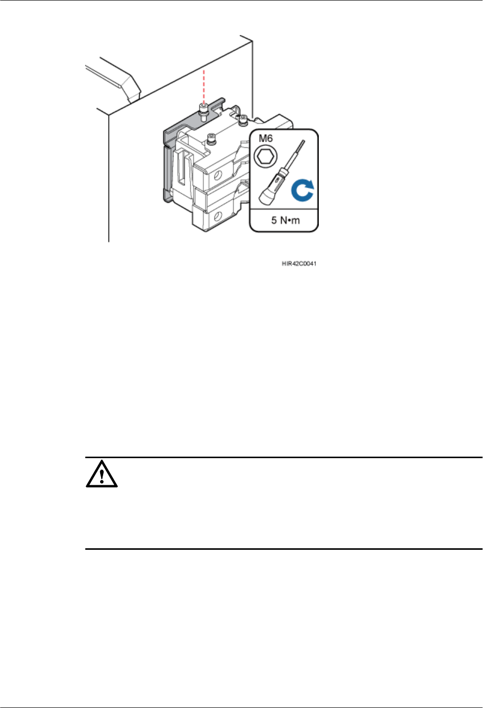
Figure 8-41 Securing the captive screw into the connection hole
----End
8.6 Installing an RRU on an IFS06
This section describes the procedure and precautions for installing an RRU on an IFS06.
Prerequisites
The hoist clamp on the main bracket is secured properly.
CAUTION
lDo not stand the RRU upright because the RF ports cannot support the weight of the RRU.
lPlace a foam pad or cardboard under the RRU to protect the RRU housing from damage
during the installation.
Context
lThe upper and lower adjustable beams on an IFS06 can be moved up and down to fit for
heights of RRUs.
lRRUs can be installed on an IFS06 only when the ambient temperature is higher than or
equal to the lowest working temperature of the RRU and at least 5°C (41°F) lower than the
highest working temperature of the RRU. In this scenario, the IFS06 supports at least three
RRUs. When the ambient temperature is higher than or equal to the lowest working
temperature of the RRU and at least 10°C (50°F) lower than the highest working
temperature of the RRU, the IFS06 supports a maximum of six RRUs.
RRU3260
Installation Guide 8 Installing the RRU
Issue () Huawei Proprietary and Confidential
Copyright © Huawei Technologies Co., Ltd.
83
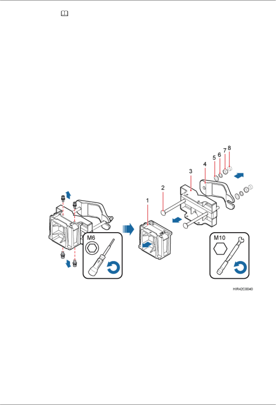
NOTE
For details about the operating temperature of the RRU, see section "Technical Specifications of
RRUs" in 3900 Series Base Station Technical Description.
lInstall RRUs in the sequence from bottom to top and from left to right.
lThis section describes how to install an RRU in height-unrestricted scenarios. The
procedure for installing an RRU in height-restricted scenarios is the same as that in height-
unrestricted scenarios.
lWhen installing the pole installation bracket, you need to use the M10x50 bolts delivered
with the IFS06.
lRubber washers are easily compressed or broken, whereas do not need to be replaced.
Procedure
Step 1 Disassemble the RRU mounting brackets, as shown in Figure 8-42.
Figure 8-42 Disassembling the mounting brackets
(1) Main bracket (2) Square-neck bolt (3) Pole installation bracket (4) Auxiliary bracket
(5) Flat washer (6) Spring washer (7) Nut (8) Plastic cap
1. Use an M6 inner hexagon torque screwdriver to remove the four inner hexagon screws on
the pole installation bracket, and remove the main bracket from the pole installation bracket.
2. Use an M10 torque wrench to loosen the nuts on the two square-neck bolts, and remove
the plastic cap, nuts, spring washers, flat washers, square-neck bolts, and pole installation
bracket from the auxiliary bracket.
Step 2 Use the M10x50 bolts delivered with the IFS06 to secure the pole installation bracket to the
IFS06, and then use an M10 torque socket wrench to secure the bolts to 30 N·m (265.52 lbf·in.).
RRU3260
Installation Guide 8 Installing the RRU
Issue () Huawei Proprietary and Confidential
Copyright © Huawei Technologies Co., Ltd.
84
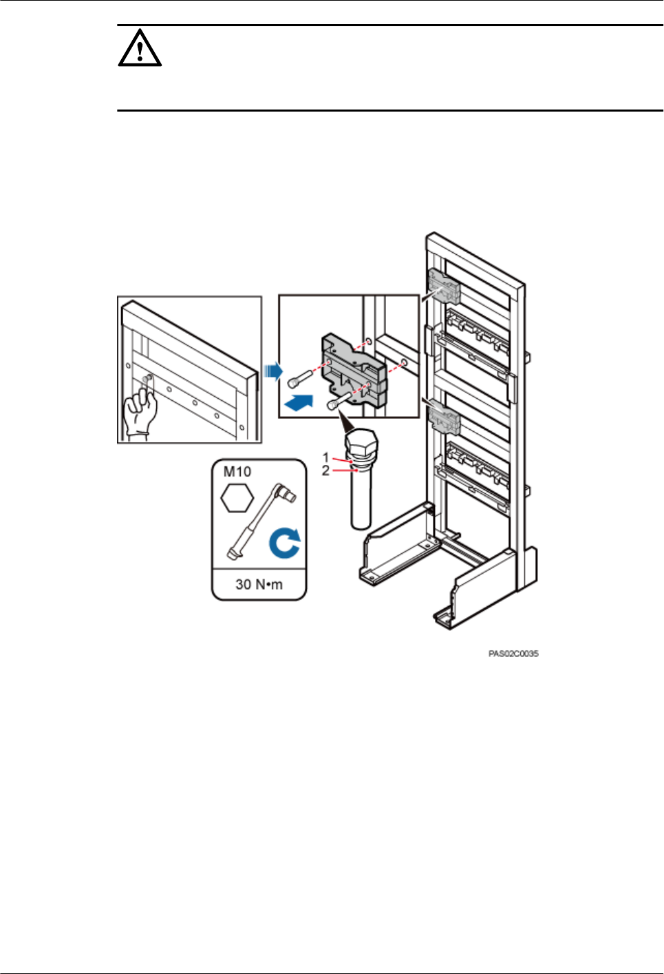
CAUTION
Ensure that the arrows on the pole installation bracket are pointing up.
lHeight-restricted scenarios
Use one finger to push and remove the rubber plugs on the beam and then install the pole
installation bracket, as shown in Figure 8-43.
Figure 8-43 Installing the pole installation bracket in height-restricted scenarios
(1) Spring washer (2) Rubber washer
lHeight-unrestricted scenarios
Install the pole installation bracket, as shown in Figure 8-44.
RRU3260
Installation Guide 8 Installing the RRU
Issue () Huawei Proprietary and Confidential
Copyright © Huawei Technologies Co., Ltd.
85
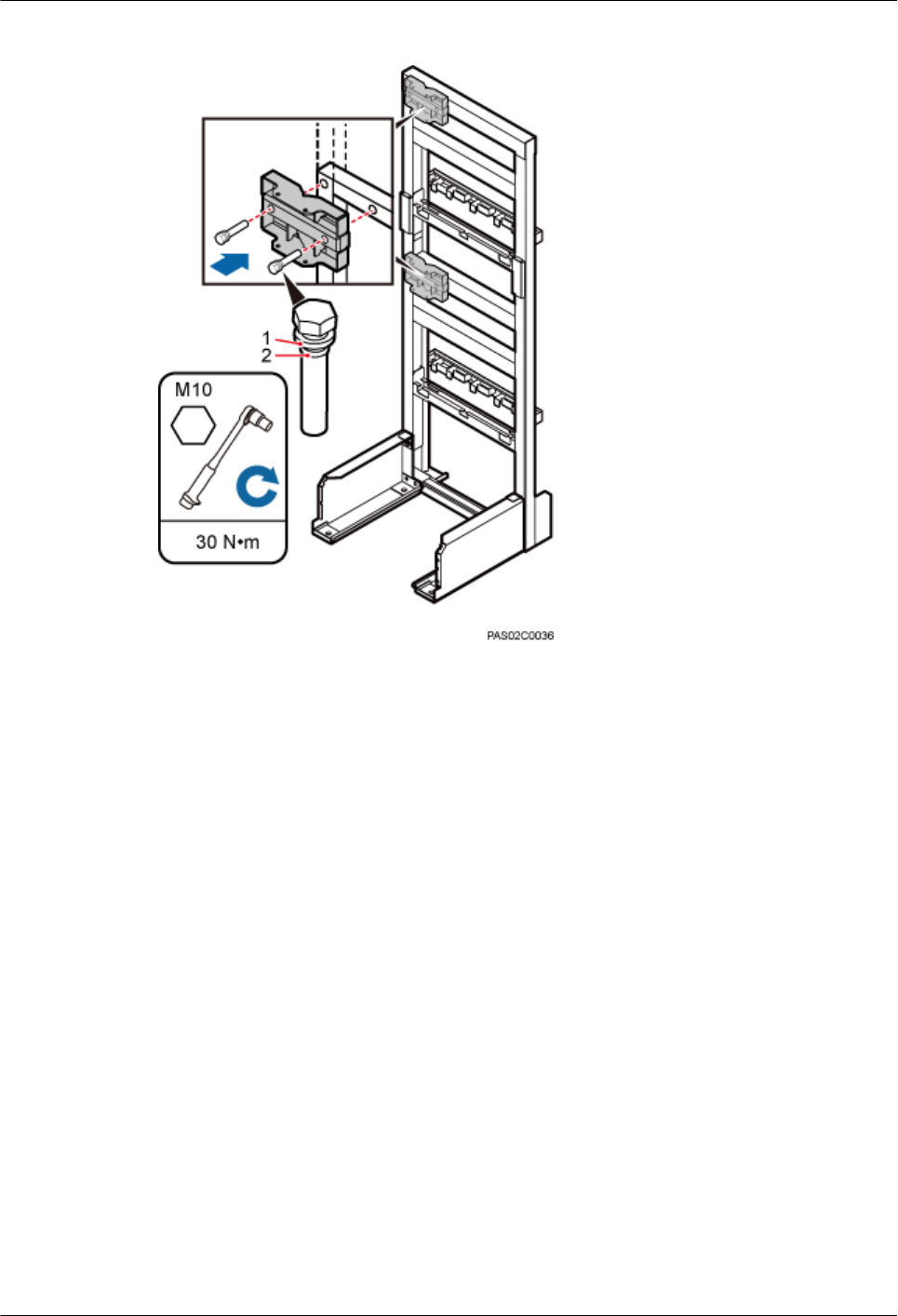
Figure 8-44 Installing the pole installation bracket in height-unrestricted scenarios
(1) Spring washer (2) Rubber washer
Step 3 Attach the main bracket to the pole installation bracket, and use an inner hexagon screwdriver
to tighten four M6x16 screws to 5 N·m (44.25 lbf·in.) so that the main bracket and pole
installation bracket are firmly secured, as shown in Figure 8-45.
RRU3260
Installation Guide 8 Installing the RRU
Issue () Huawei Proprietary and Confidential
Copyright © Huawei Technologies Co., Ltd.
86
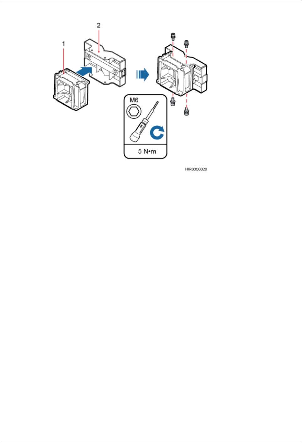
Figure 8-45 Installing the main bracket
(1) Main bracket (2) Pole installation bracket
Step 4 Attach the RRU to the main bracket, and then use an inner hexagon screwdriver to tighten the
captive screw into the holes of the attachment plate and main bracket to 5 N·m (44.25 lbf·in.) so
that the attachment plate and main bracket are firmly secured, as shown in Figure 8-46.
RRU3260
Installation Guide 8 Installing the RRU
Issue () Huawei Proprietary and Confidential
Copyright © Huawei Technologies Co., Ltd.
87
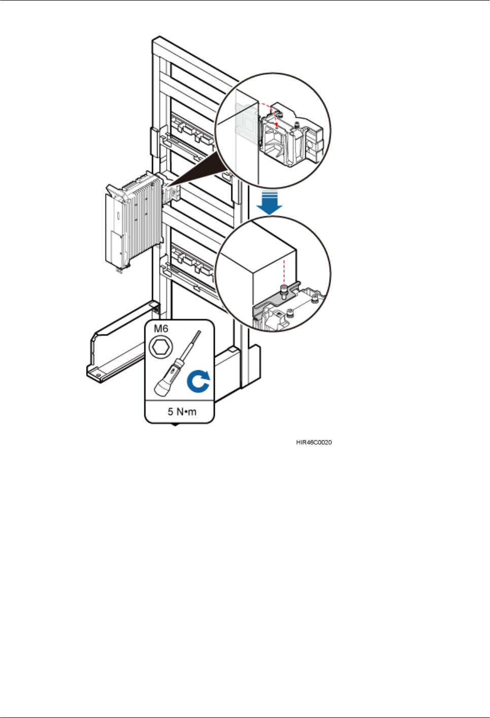
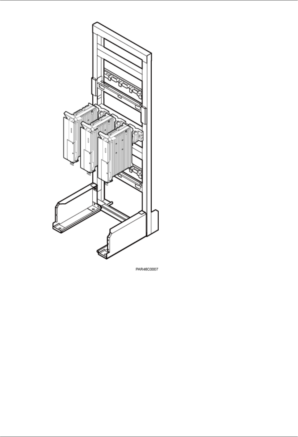
Figure 8-47 Installing RRUs on the lower level
Step 6 Optional: When the ambient temperature is equal to or higher than the lowest operating
temperature of the RRU and at least 10°C (10°F) lower than the highest operating temperature
of the RRU, repeat the preceding steps to install the RRUs on the higher level, as shown in
Figure 8-48.
RRU3260
Installation Guide 8 Installing the RRU
Issue () Huawei Proprietary and Confidential
Copyright © Huawei Technologies Co., Ltd.
89
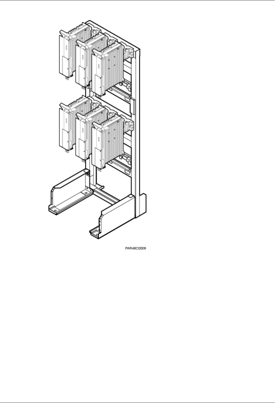
Figure 8-48 Installing RRUs on the higher level
----End
RRU3260
Installation Guide 8 Installing the RRU
Issue () Huawei Proprietary and Confidential
Copyright © Huawei Technologies Co., Ltd.
90

9 Installing RRU Cables
About This Chapter
This chapter describes the procedure for installing RRU cables.
9.1 Cabling Requirements
Cables must be routed according to the specified cabling requirements to prevent signal
interference.
9.2 Cable Connections
This section describes the cable connections for a single RRU and multiple RRUs.
9.3 Installation Process
This section describes the process of installing RRU cables.
9.4 RRU Cable List
This section describes RRU cable connections.
9.5 Installing an RRU PGND Cable
This section describes the procedure for installing an RRU PGND cable.
9.6 Installing an RRU RF Jumper
This section describes the procedure for installing an RRU RF jumper.
9.7 Installing an RRU AISG Multi-Wire Cable and AISG Extension Cable
This section describes the procedures for installing an RRU AISG multi-wire cable and AISG
extension cable.
9.8 Installing an RRU Alarm Cable
This section describes the procedure for installing an RRU alarm cable.
9.9 Opening the Cover Plate of an RRU Cabling Cavity
This section describes the procedure for opening the cover plate of an RRU cabling cavity.
9.10 Installing an RRU Power Cable
This section describes the procedure for installing an RRU power cable.
9.11 Installing a CPRI Fiber Optic Cable
This section describes the procedure for installing a CPRI fiber optic cable.
9.12 Closing the Cover Plate of an RRU Cabling Cavity
RRU3260
Installation Guide 9 Installing RRU Cables
Issue () Huawei Proprietary and Confidential
Copyright © Huawei Technologies Co., Ltd.
91


9.1 Cabling Requirements
Cables must be routed according to the specified cabling requirements to prevent signal
interference.
NOTE
If a cable listed below is not required, skip the routing requirements of the cable.
General Cabling Requirements
Requirements for Bending Radius
lThe bending radius of the 7/8'' feeder must be more than 250 mm (9.84 in.), and the bending
radius of the 5/4'' feeder must be more than 380 mm (14.96 in.).
lThe bending radius of the 1/4'' jumper must be more than 35 mm (1.38 in.). The bending
radius of the super-flexible 1/2'' jumper must be more than 50 mm (1.97 in.), and the bending
radius of the ordinary 1/2'' jumper must be more than 127 mm (5 in.).
lThe bending radius of the power cable or PGND cable must be at least three times the
diameter of the cable.
lThe bending radius of a fiber optic cable is at least 20 times the diameter of the fiber optic
cable, and the minimum bending radius of the breakout cable at each end of the fiber optic
cable is 30 mm (1.18 in.).
lThe bending radius of the E1/T1 cable must be at least three times the diameter of the cable.
lThe bending radius of the signal cable must be at least five times the diameter of the cable.
Requirements for Cable Binding
lThe same types of cable must be bound together.
lDifferent types of cable must be separately routed with the minimum spacing of 30 mm
(1.18 in.) and cannot be entangled.
lThe cables must be bound tightly and neatly. The sheaths of the cables must not be damaged.
lCable ties are installed in the same direction, and those at the same horizontal line must be
in a straight line.
lThe excess of indoor cable ties is trimmed off, and the excess of outdoor cable ties allows
about 5 mm (0.2 in.), without remaining rough edges.
lLabels or nameplates must be attached to both ends, joints, or turns of cables after they are
installed.
Security Requirements
lCables should be placed away from sharp objects or wall burrs. If these positions are
inevitable, protect the cables with protection pipes.
lCables must be routed away from heat sources, or heat-insulation materials are added
between cables and heat sources.
lSufficient slack (recommended for about 0.1 m [0.33 ft]) is provided in cables at turns or
the position close to a device, facilitating cable and device maintenance.
Indoor Cabling Requirements
lCables are routed indoors through the feeder window.
RRU3260
Installation Guide 9 Installing RRU Cables
Issue () Huawei Proprietary and Confidential
Copyright © Huawei Technologies Co., Ltd.
93
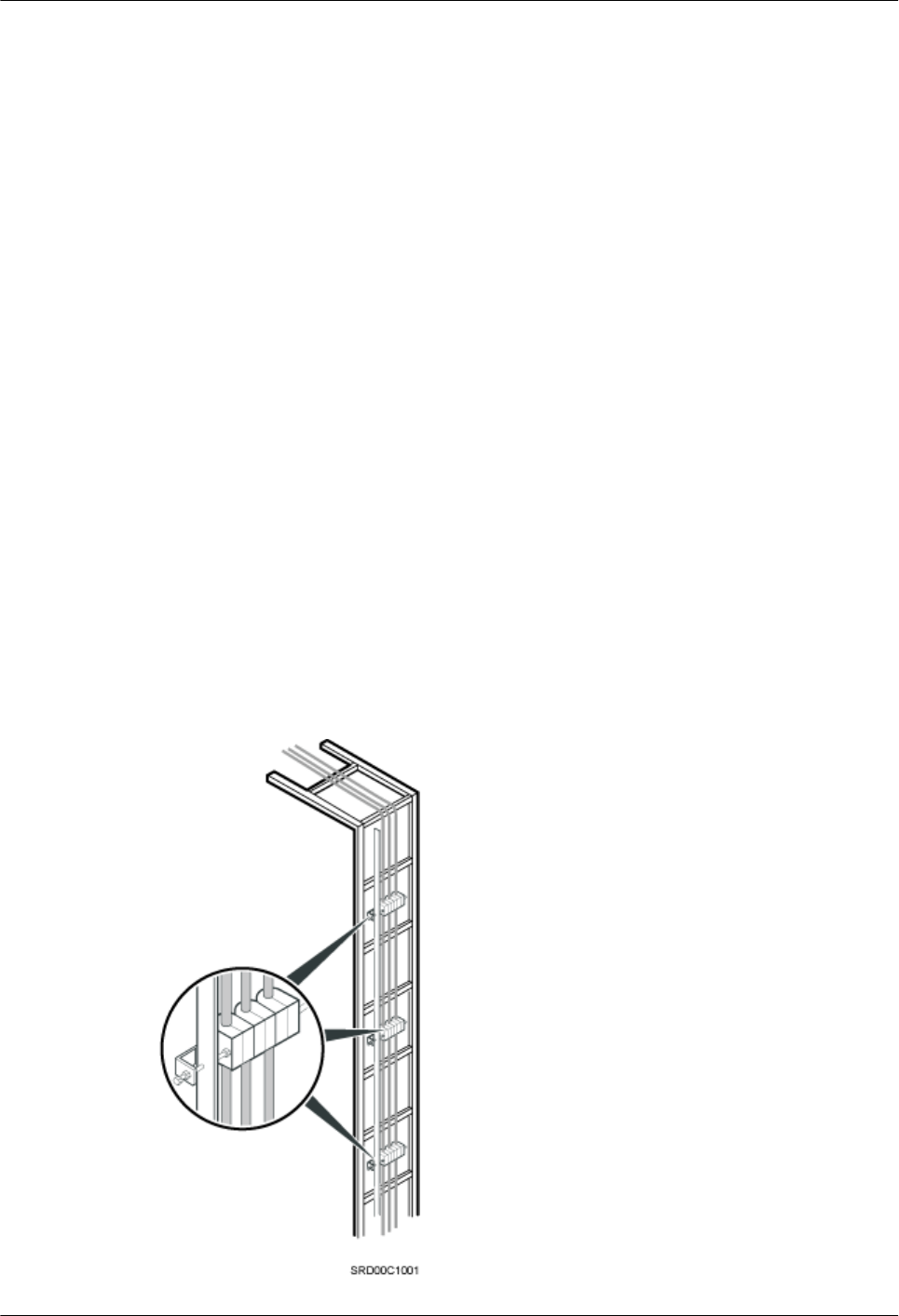
lDrip loops must be made outside the feeder window, and the requirements for the minimum
bending radius are met.
lWhen cables are routed indoors, engineers are required indoors for cooperation.
lThe feeder window must be waterproofed.
Outdoor Cabling Requirements
lCables routed outdoors must be led through a pipe when they may be damaged.
lAC power cables, transmission cables, and cables buried in the ground must be protected.
lIf cables at the cabinet bottom need to be routed through a pipe along the ground, lead the
pipe into the cabinet base for about 30 mm (1.18 in.) to 50 mm (1.97 in.), not into the
cabinet. Block the pipe with waterproof tape or silicon gel, and secure the pipe to the cable
hole at the cabinet bottom with metal piece.
lIf cables at the cabinet bottom need to be routed through a pipe along the metal cable trough,
do not lead the pipe into the cabinet base. The cable trough must be sealed and routed
through the cable hole at the cabinet bottom.
lCables are secured with cable clips.
lCables are routed neatly along the specified cabling direction and secured with cable clips.
lThe positions for cable clips are determined onsite. For example, the cable clips for the
7/8" feeder are installed at the spacing of 1.5 m (4.92 ft) to 2 m (6.56 ft) in the same direction,
and the cable clips for the power cables are installed at the spacing of 1.5 m (4.92 ft) to 2
m (6.56 ft) in the same direction.
lCable clips must be vertical with cables, and the cables in a cable clip must be parallel.
lAfter routing cables neatly and correctly, tighten the screws on cable clips.
Secure cables on the cable tray, as shown in Figure 9-1.
Figure 9-1 Securing cables on the cable tray
RRU3260
Installation Guide 9 Installing RRU Cables
Issue () Huawei Proprietary and Confidential
Copyright © Huawei Technologies Co., Ltd.
94
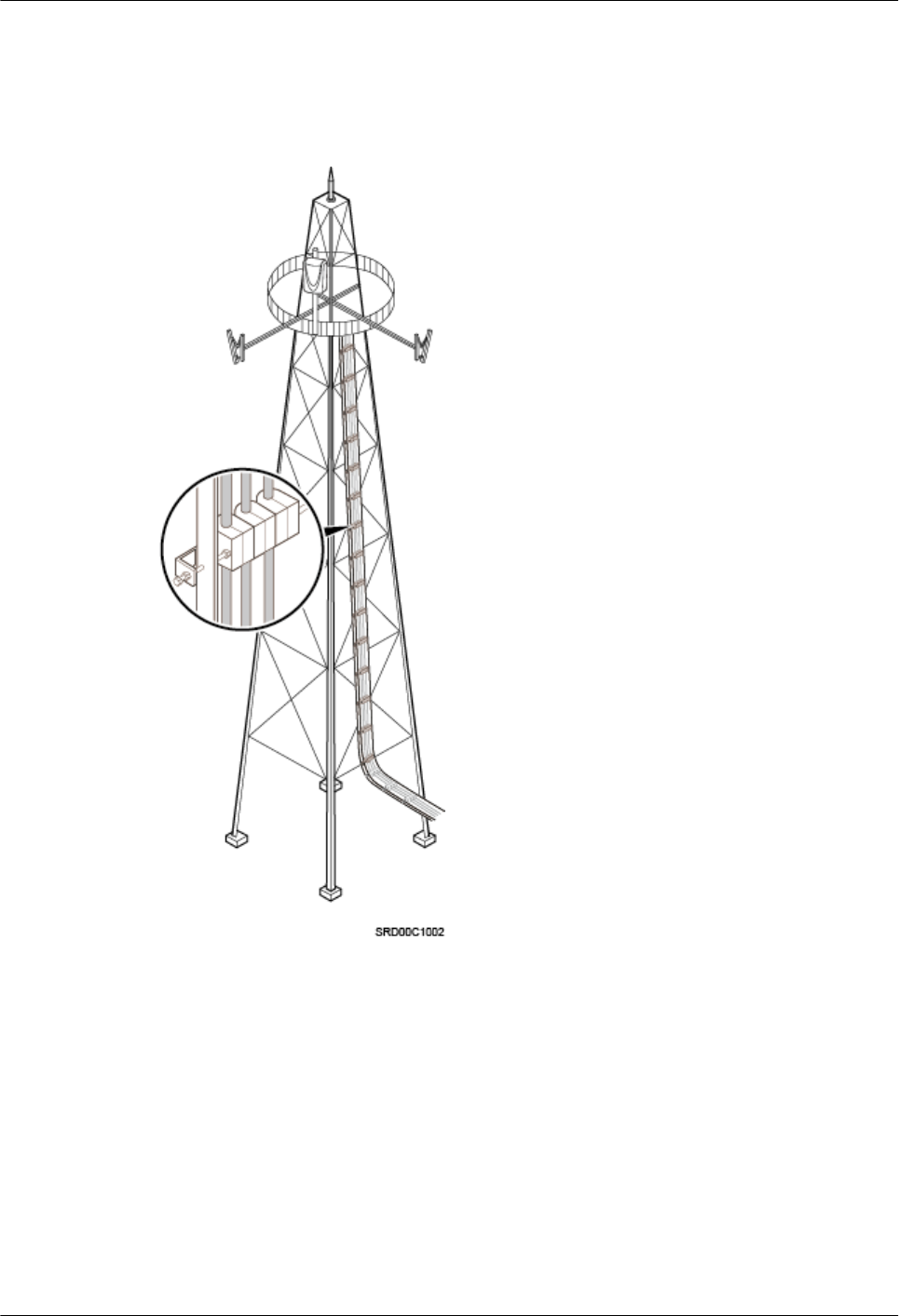
Secure cables on the tower, as shown in Figure 9-2.
Figure 9-2 Securing cables on the tower
Special Cabling Requirements
Cabling Requirements for Power Cables
lPower cables must be installed in the position specified in engineering design documents.
lIf the length of power cables is insufficient, replace the cables rather than adding connectors
or soldering joints to lengthen the cables.
lCables must be routed by only qualified and trained personnel before all preparations are
made.
lCables are routed in an untangled and orderly fashion.
RRU3260
Installation Guide 9 Installing RRU Cables
Issue () Huawei Proprietary and Confidential
Copyright © Huawei Technologies Co., Ltd.
95
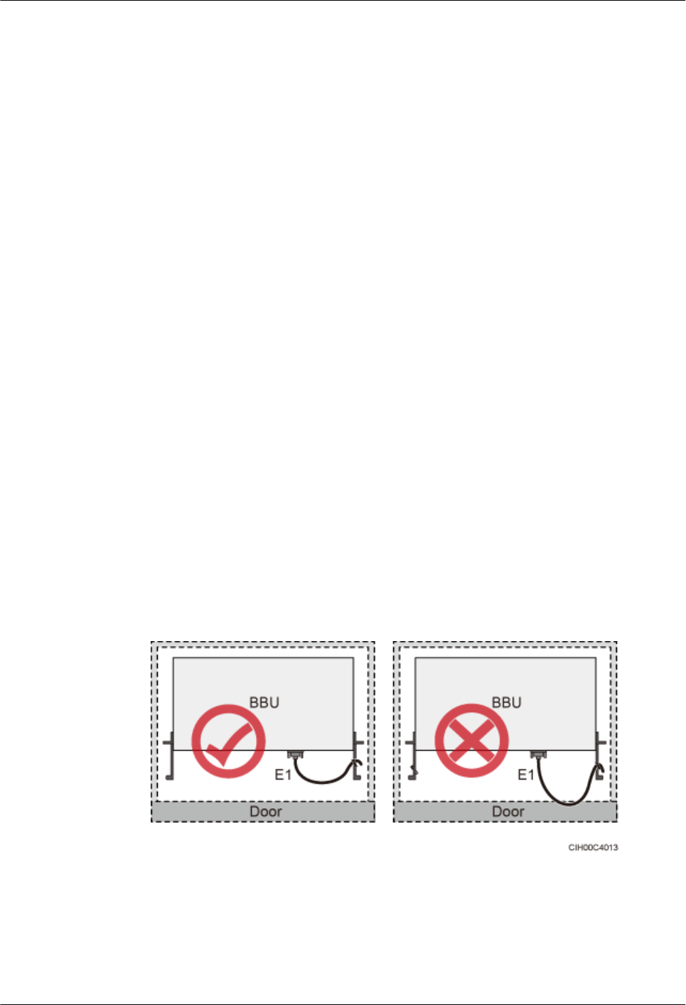
lIf DC power cables need to be routed on the tower platform, lay out the cables on the
guardrail with the shortest distance and route the cables along the guardrail.
lIf DC power cables need to be routed close to a device on the tower, secure the cables to
the guardrail or pole with cable clips. The device cannot be far away from the position for
securing the cables.
Cabling Requirements for PGND Cables
lPGND cables for the base station must be connected to the same ground bar.
lPGND cables must be buried in the ground or routed indoors. They should not be routed
overhead before they are led into the equipment room.
lThe exterior of the coaxial wire and the shield layer of the shielded cable must have proper
electrical contact with the metal surface of the equipment to which they are connected.
lPGND cables and signal cables must be installed in an untangled and orderly fashion. A
certain distance must be reserved between them to prevent interference from each other.
lFuses or switches must not be installed on the PGND cables.
lOther devices must not be used for electrical connections of the PGND cables.
lAll the metal parts in the housing of the equipment must be reliably connected to the ground
terminal.
Cabling Requirements for E1 Cables
lE1 cables must not cross power cables, PGND cables, or RF cables when routed. If
transmission cables are routed with power cables, PGND cables, or RF cables in parallel,
the spacing between them must be greater than 30 mm (1.18 in.).
lE1 cables are routed straightly and bound neatly with cable ties.
lSufficient slack is provided in E1 cables at turns.
lE1 cables cannot be squeezed by the cabinet door when routed through the cabinet, as
shown in Figure 9-3.
Figure 9-3 E1 cables routed through the cabinet
Cabling Requirements for Fiber Optic Cables
lFiber optic cables must be routed by at least three qualified and trained personnel before
all preparations are made.
RRU3260
Installation Guide 9 Installing RRU Cables
Issue () Huawei Proprietary and Confidential
Copyright © Huawei Technologies Co., Ltd.
96
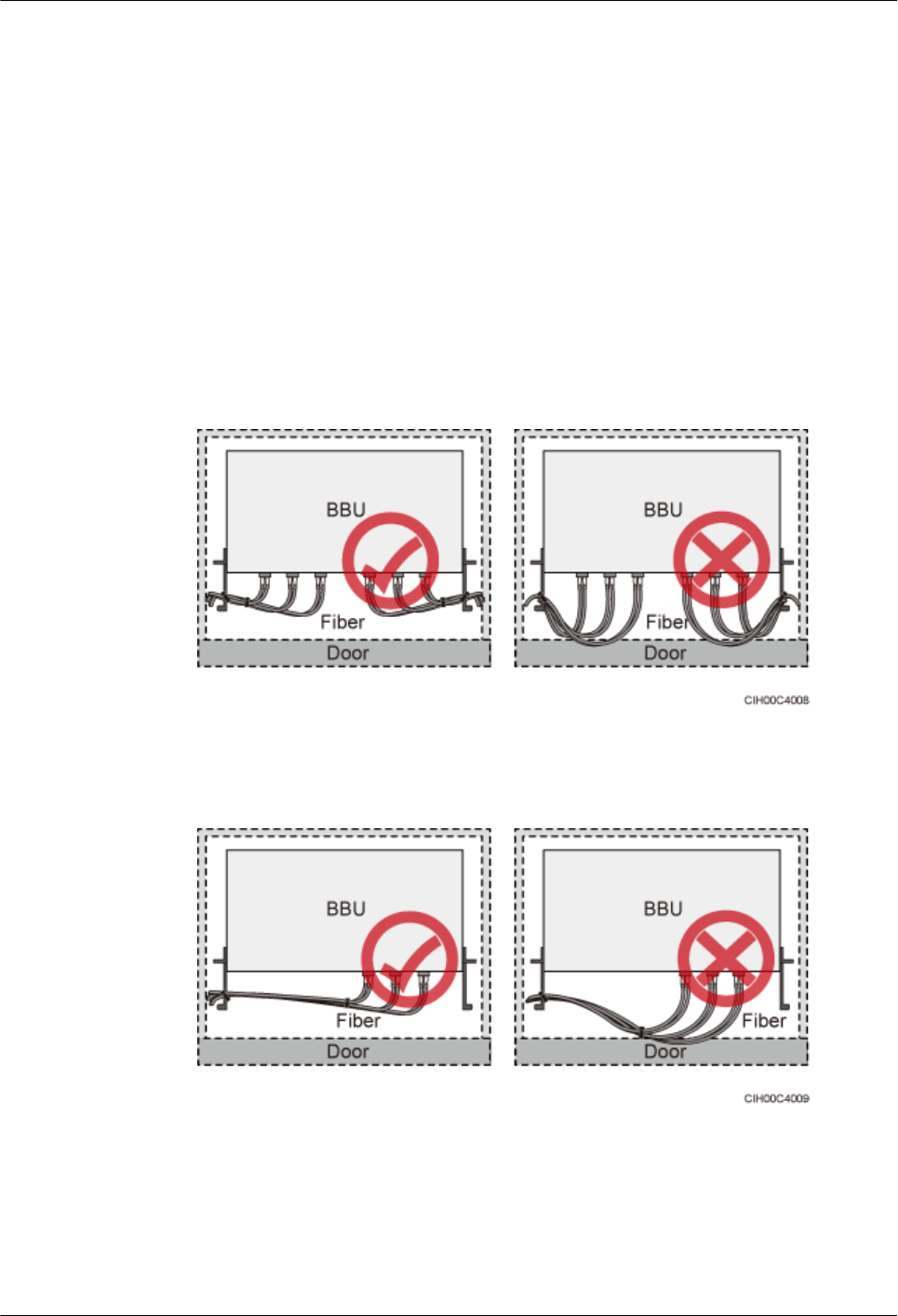
lFiber optic cables are used within the temperature range of -40°C to 60°C. If the current
temperature is out of the range, make protection measures or route the cables again.
lCables are routed in an untangled and orderly fashion.
lDo not bind fiber optic cables at turns.
lDo not stretch, step on, or place heavy objects on fiber optic cables. Keep the cables away
from sharp objects.
lWhen fiber optic cables are routed, the excess of the cables must be coiled around special
devices, such as a fiber coiler.
lWhen coiling fiber optic cables, apply even strength. Do not bend the cables with force.
lVacant optical connectors must be covered with dustproof caps.
lFiber optic cables cannot be squeezed by the cabinet door when routed through the cabinet,
as shown in Figure 9-4, Figure 9-5 and Figure 9-6.
Figure 9-4 CPRI fiber optic cables routed through the cabinet (1)
Figure 9-5 CPRI fiber optic cables routed through the cabinet (2)
RRU3260
Installation Guide 9 Installing RRU Cables
Issue () Huawei Proprietary and Confidential
Copyright © Huawei Technologies Co., Ltd.
97
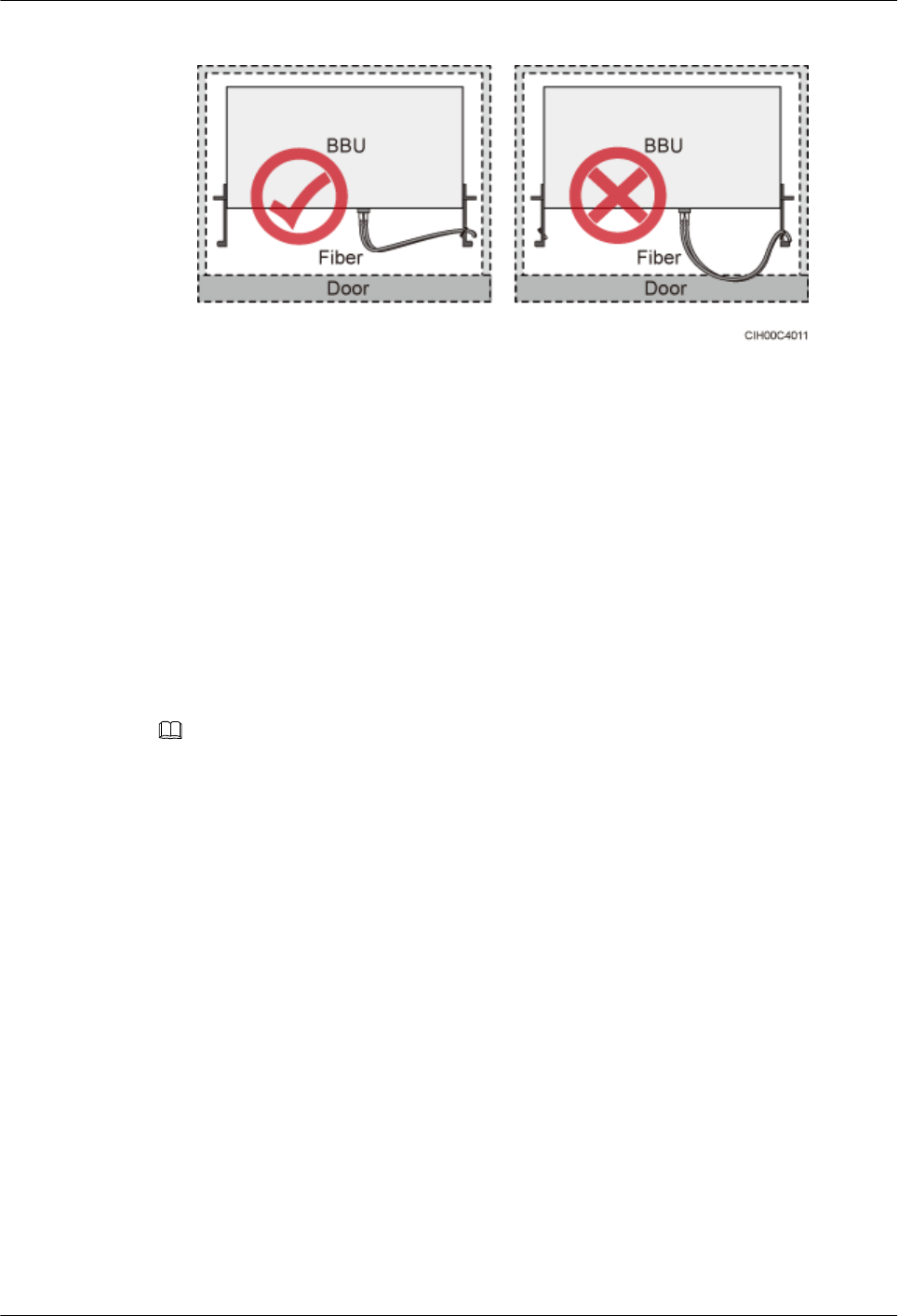
Figure 9-6 FE/GE cables routed through the cabinet
lIf fiber optic cables need to be routed on the tower platform, lay out the cables on the
guardrail with the shortest distance and route the cables along the guardrail.
lIf fiber optic cables need to be routed close to a device on the tower, secure the cables to
the guardrail or pole with cable clips. The device cannot be far away from the position for
securing the cables.
lIf the fiber optic cables close to a device are too long, coil the excess of the cables and
secure them on the tower.
9.2 Cable Connections
This section describes the cable connections for a single RRU and multiple RRUs.
NOTE
lA lower-level RRU obtains power directly from the external power system, but not from an upper-
level RRU using a power cable.
Figure 9-7 shows the cable connections for a single RRU.
RRU3260
Installation Guide 9 Installing RRU Cables
Issue () Huawei Proprietary and Confidential
Copyright © Huawei Technologies Co., Ltd.
98
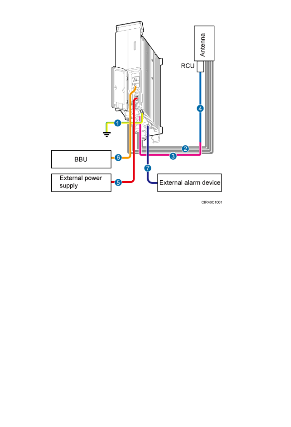
Figure 9-7 Cable connections for a single RRU
(1) PGND cable (2) RRU RF jumper (3) RRU AISG multi-wire cable
(4) RRU AISG extension cable (5) RRU power cable (6) CPRI fiber optic cable
(7) RRU alarm cable - -
Figure 9-8 shows the cable connections for multiple RRUs.
RRU3260
Installation Guide 9 Installing RRU Cables
Issue () Huawei Proprietary and Confidential
Copyright © Huawei Technologies Co., Ltd.
99
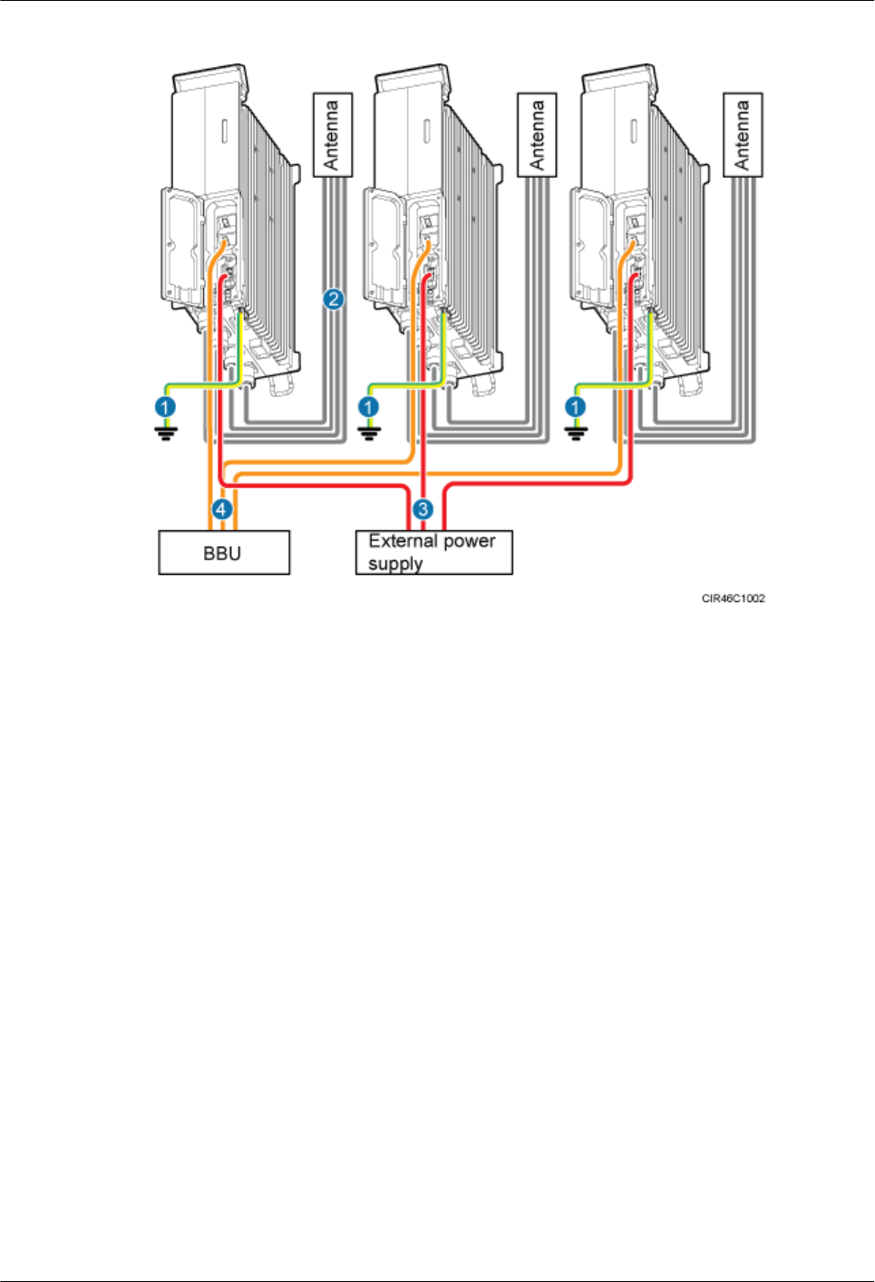
Figure 9-8 Cable connections for multiple RRUs
(1) PGND cable (2) RRU RF jumper (3) RRU power cable
(4) CPRI fiber optic cable - -
9.3 Installation Process
This section describes the process of installing RRU cables.
Figure 9-9 shows the process of installing RRU cables.
RRU3260
Installation Guide 9 Installing RRU Cables
Issue () Huawei Proprietary and Confidential
Copyright © Huawei Technologies Co., Ltd.
100
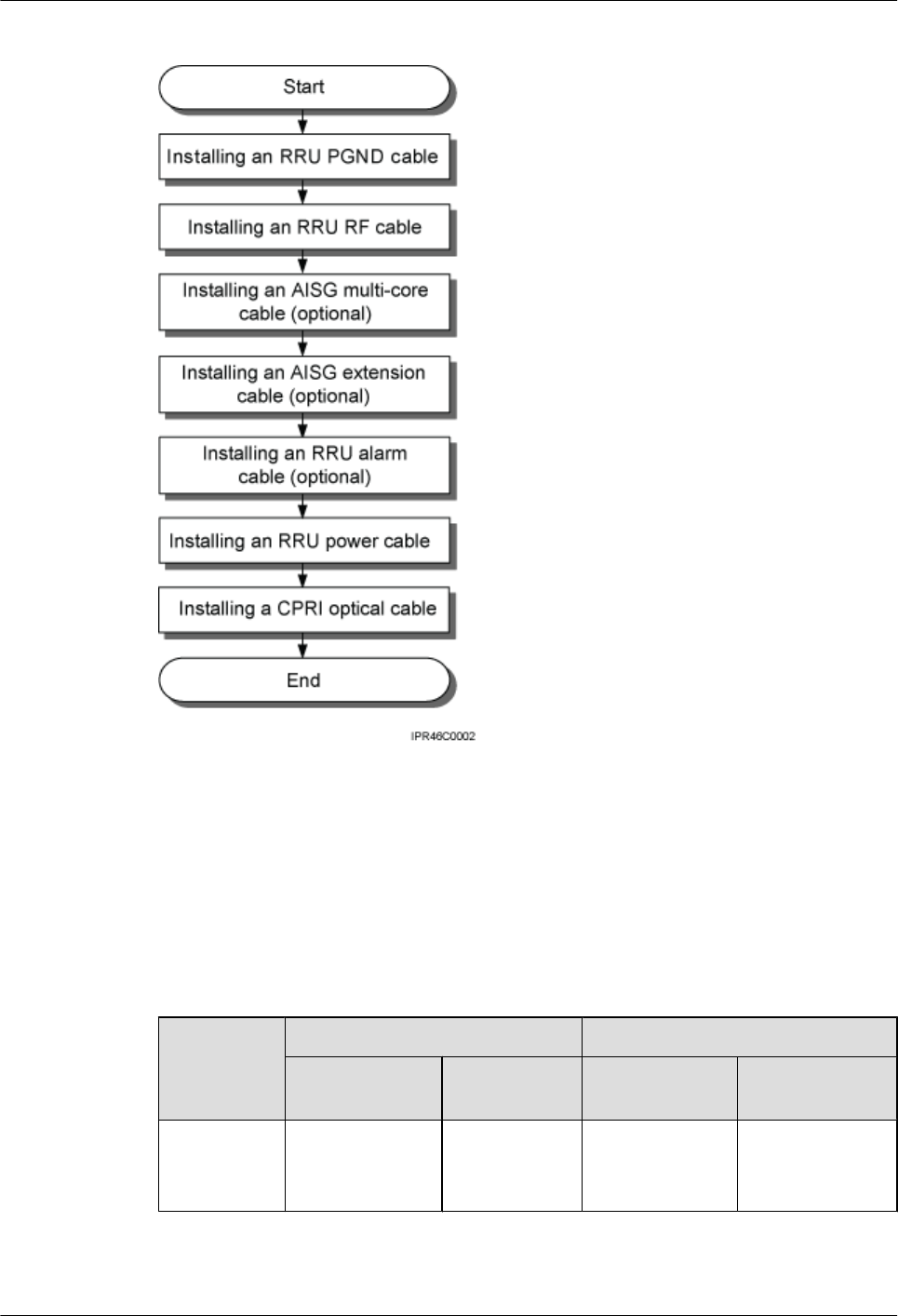
Figure 9-9 Process of installing RRU cables
9.4 RRU Cable List
This section describes RRU cable connections.
Table 9-1 lists RRU cables.
Table 9-1 RRU cables
Cable One End The Other End
Connector Installation
Position
Connector Installation
Position
RRU PGND
Cable
OT terminal (16
mm2 or 0.025 in.
2, M6)
Ground
terminal on the
RRU
OT terminal (16
mm2 or 0.025 in.
2, M8)
Ground terminal
on the ground bar
RRU3260
Installation Guide 9 Installing RRU Cables
Issue () Huawei Proprietary and Confidential
Copyright © Huawei Technologies Co., Ltd.
101

Cable One End The Other End
Connector Installation
Position
Connector Installation
Position
RRU Power
Cable
Tool-less female
connector
(pressfit type)
NEG(-) and
RTN(+) ports
on the RRU
Tool-less female
connector
(pressfit type)
One of RRU0 to
RRU5 ports on
the EPU or EPS
One of LOAD0 to
LOAD5 ports on
the DCDU-11B
OT terminal (3.3
mm2 or 0.005 in.
2, 5.3 mm2 or
0.0082 in.2, M4),
complying with
North American
standards
OT terminal (4
mm2 or 0.006 in.
2, 6 mm2 or
0.0093 in.2, M4),
complying with
European
standards
One of LOAD0 to
LOAD5 ports on
the DCDU-03B
RRU Alarm
Cable
DB15 waterproof
male connector
EXT_ALM
port on the
RRU
Cord end
terminal
External alarm
device
CPRI Fiber
Optic Cable
DLC connector CPRI0 port on
the RRU
DLC connector CPRI port on the
WBBP in the
BBU
CPRI1 port on
the RRU
CPRI0 port on the
RRU
RRU RF
Jumper
DIN male
connector
ANT_TX/
RXA or
ANT_TX/
RXB port on
the RRU
DIN male
connector
Antenna system
RRU AISG
Multi-Wire
Cable
DB9
waterproofed
male connector
RET port on
the RRU
Standard AISG
female connector
Standard AISG
male connector
on the RCU or on
the AISG
extension cable
RRU3260
Installation Guide 9 Installing RRU Cables
Issue () Huawei Proprietary and Confidential
Copyright © Huawei Technologies Co., Ltd.
102
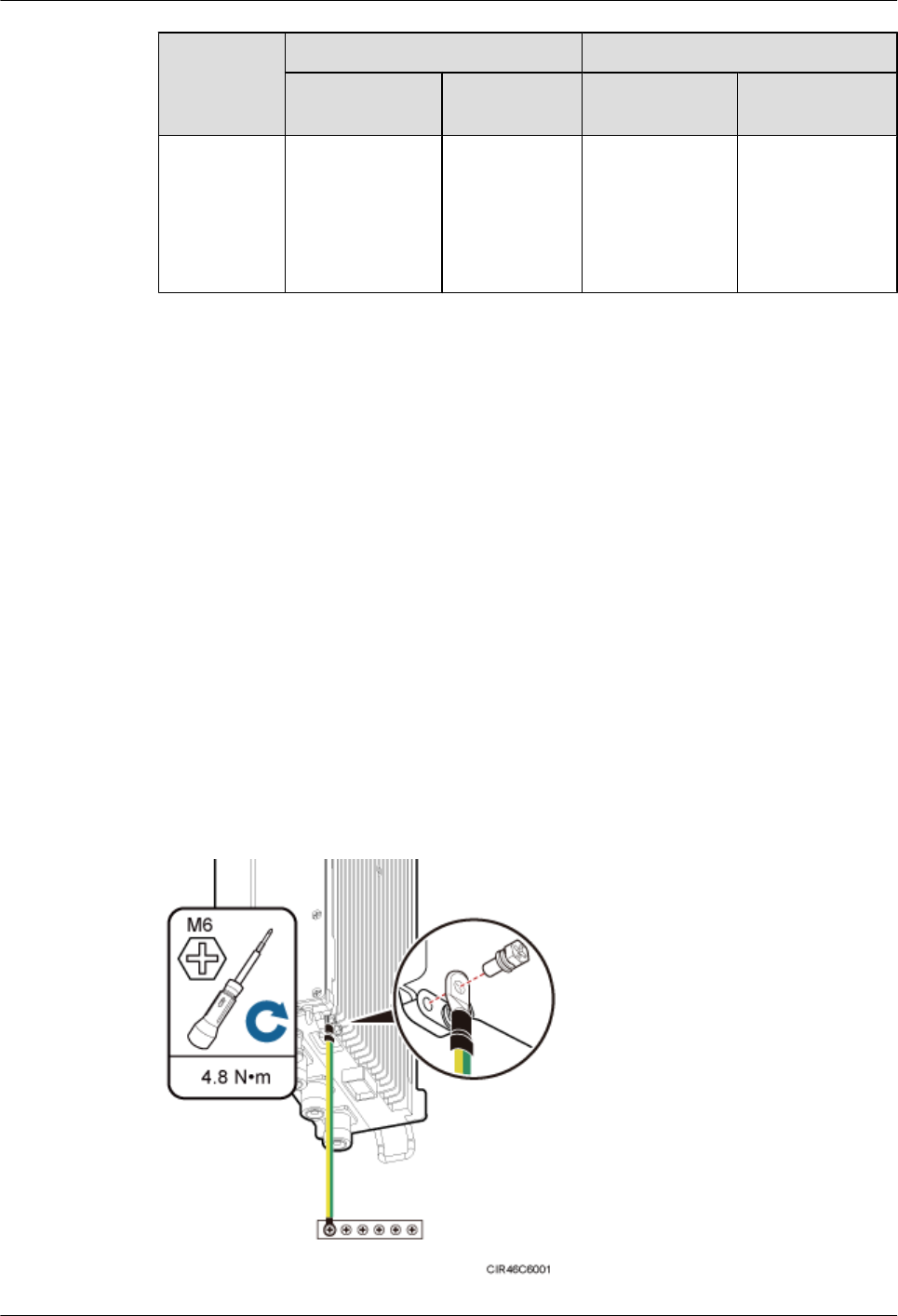
Cable One End The Other End
Connector Installation
Position
Connector Installation
Position
RRU AISG
Extension
Cable
Standard AISG
male connector
Standard AISG
female
connector on
the AISG
multi-wire
cable
Standard AISG
female connector
Standard AISG
male connector
on the RCU
9.5 Installing an RRU PGND Cable
This section describes the procedure for installing an RRU PGND cable.
Context
The cross-sectional area of an RRU PGND cable is 16 mm2 (0.025 in.2). The cable has an M6
OT terminal at one end and an M8 terminal at the other end.
Procedure
Step 1 According to the actual cable route, cut the PGND cable into a proper length to prepare an RRU
PGND cable. Then add an OT terminal at each end of the cable according to the instructions in
Assembling the OT Terminal and the Power Cable.
Step 2 Install the RRU PGND cable.
Connect the M6 OT terminal at one end of the PGND cable to the ground terminal at the RRU
bottom and the M8 OT terminal at the other end to the external ground bar, as shown in Figure
9-10.
Figure 9-10 Installing an RRU PGND cable
RRU3260
Installation Guide 9 Installing RRU Cables
Issue () Huawei Proprietary and Confidential
Copyright © Huawei Technologies Co., Ltd.
103
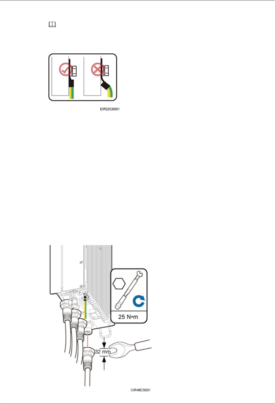
NOTE
Crimp OT terminals in correct positions, as shown in Figure 9-11.
Figure 9-11 Correct position of an OT terminal
Step 3 Label the installed cables according to the instructions in Attaching a Cable-Tying Label.
----End
9.6 Installing an RRU RF Jumper
This section describes the procedure for installing an RRU RF jumper.
Procedure
Step 1 Connect the DIN male connector at one end of the RRU RF jumper to the ANT port on the RRU,
and use a torque wrench to tighten the connector to 25 N·m (221.27 lbf·in.), as shown in Figure
9-12.
Figure 9-12 Installing an RRU RF jumper
RRU3260
Installation Guide 9 Installing RRU Cables
Issue () Huawei Proprietary and Confidential
Copyright © Huawei Technologies Co., Ltd.
104
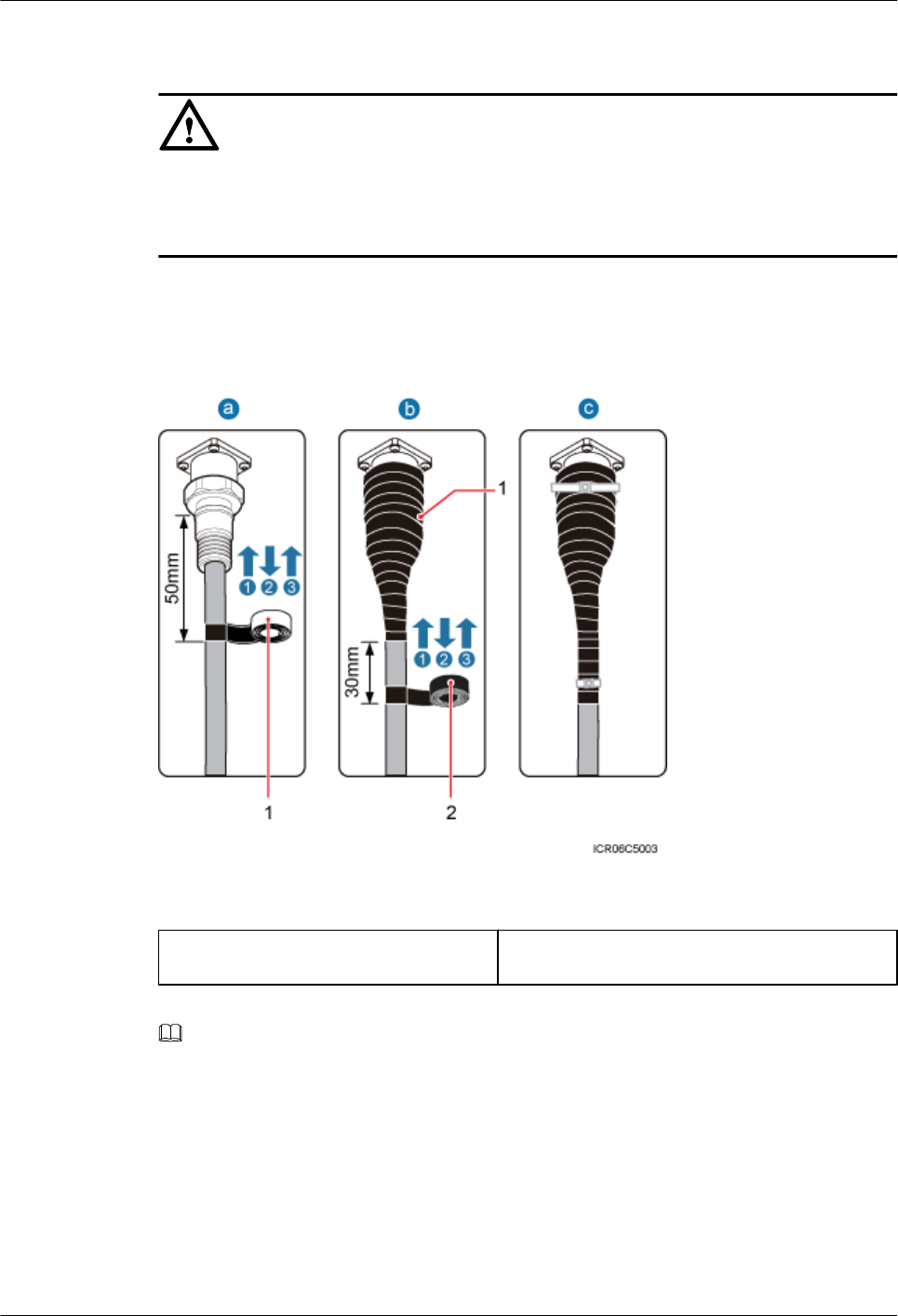
CAUTION
On AC-powered electric railways, such as high speed railways, when leaky cables are connected
to RRUs installed in tunnels, high-voltage-resistance DC blocks must be installed between RRU
RF jumpers and the leaky cables to protect the RRUs against damage.
Step 2 Link the other end of the RF jumper to the external antenna system.
Step 3 Waterproof the connectors of the RF jumper by referring to Figure 9-13.
Figure 9-13 Waterproofing a connector of the RF jumper
(1) Waterproof tape (2) PVC insulation tape
NOTE
lBefore wrapping waterproof tape, stretch the tape evenly until the length of the tape becomes twice its
original length.
lDo not stretch the PVC insulation tape when wrapping the PVC insulation tape.
lWrap each layer of tape around the connector tightly and neatly, and ensure that each layer of tape overlaps
more than 50% of the preceding layer. Ensure that neighboring layers are stuck to each other.
lEnsure that the adhesive surface of the tape overlaps the lower layer.
lWhen cutting off the cable ties, reserve a redundant length of 3 mm (0.12 in.) to 5 mm (0.2 in.).
1. Wrap three layers of waterproof tape on the connector, first from bottom up, then from top
down, and finally from bottom up. Start wrapping the connector at a position 50 mm (1.97
RRU3260
Installation Guide 9 Installing RRU Cables
Issue () Huawei Proprietary and Confidential
Copyright © Huawei Technologies Co., Ltd.
105
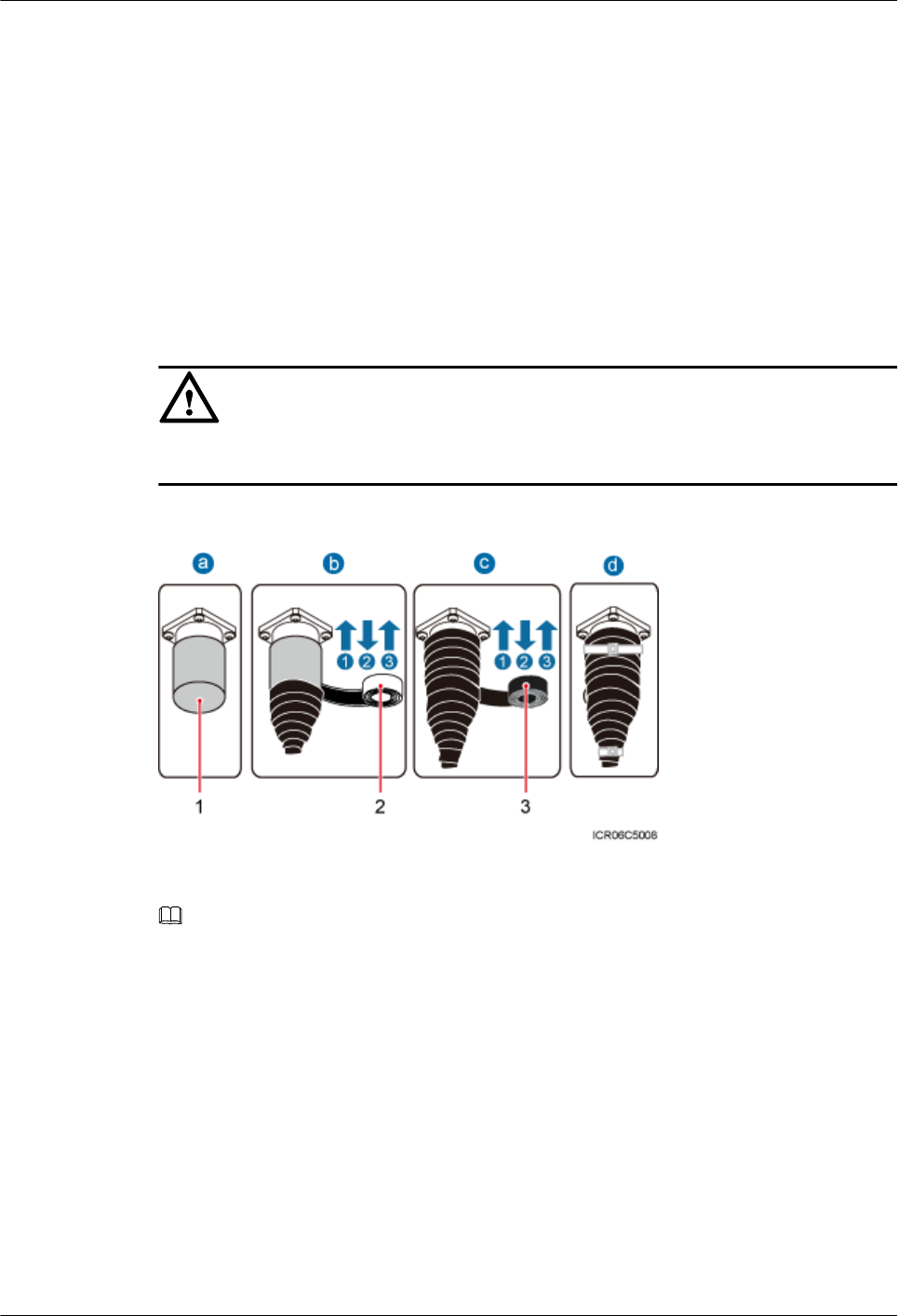
in.) away below the bottom of the connector to the top of the connector, first from bottom
up, then from top down, and finally from bottom up. Cut off the redundant tape after three
layers are wrapped. Wrap each layer of tape around the connector tightly.
2. Wrap three layers of PVC insulation tape. Start the wrapping at a position 30 mm (1.18 in.)
away below the bottom of the waterproof tape to the top of the connector, first from bottom
up, then from top down, and finally from bottom up. Cut off the redundant tape after three
layers are wrapped. Wrap each layer of tape around the connector tightly.
3. Start binding cable ties to the cable at a position 3 mm (0.12 in.) to 5 mm (0.2 in.) away
from one end of the PVC insulation tape.
Step 4 Check the dustproof caps on antenna connectors. In outdoor scenarios, dustproof caps must be
waterproofed, as shown in Figure 9-14.
CAUTION
Do not remove dustproof caps from vacant antenna connectors.
Figure 9-14 Waterproofing a dustproof cap
(1) Dustproof cap (2) Waterproof tape (3) PVC insulation tape
NOTE
lBefore wrapping waterproof tape, stretch the tape evenly until the length of the tape becomes twice its
original length.
lDo not stretch the PVC insulation tape when wrapping the PVC insulation tape.
lWrap each layer of tape around the connector tightly and neatly, and ensure that each layer of tape overlaps
more than 50% of the preceding layer. Ensure that neighboring layers are stuck to each other.
lEnsure that the adhesive surface of the tape overlaps the lower layer.
lWhen cutting off the cable ties, reserve a redundant length of 3 mm (0.12 in.) to 5 mm (0.2 in.).
1. Verify that dustproof caps are not removed.
2. Wrap three layers of waterproof tape on the connector, first from bottom up, then from top
down, and finally from bottom up. Wrap each connector with three layers of waterproof
tape, from bottom up, then from top down, and finally from bottom up. Do not cut the tape
RRU3260
Installation Guide 9 Installing RRU Cables
Issue () Huawei Proprietary and Confidential
Copyright © Huawei Technologies Co., Ltd.
106

until all the three layers of the tape are already wrapped. Cut off the redundant tape after
three layers are wrapped. Wrap each layer of tape around the connector tightly.
3. Wrap three layers of PVC insulation tape. Wrap each connector with three layers of
waterproof tape, from bottom up, then from top down, and finally from bottom up. Do not
cut the tape until all the three layers of the tape are already wrapped. Cut off the redundant
tape after three layers are wrapped. Wrap each layer of tape around the connector tightly.
4. Start binding cable ties to the cable at a position 3 mm (0.12 in.) to 5 mm (0.2 in.) away
from one end of the PVC insulation tape.
Step 5 Route the cables according to the instructions in 9.1 Cabling Requirements, and then use cable
ties to bind the cables.
Step 6 Label the installed cables according to the instructions in Attaching a Sign Plate Label.
Step 7 Attach color-coding to the installed RF jumper according to the instructions in Attaching the
Color Ring.
----End
9.7 Installing an RRU AISG Multi-Wire Cable and AISG
Extension Cable
This section describes the procedures for installing an RRU AISG multi-wire cable and AISG
extension cable.
Context
When the distance between an RRU and a Remote Control Unit (RCU) is longer than 5 m (16.4
ft.), an AISG multi-wire cable is not long enough to connect the RRU and the RCU. In this case,
an AISG extension cable is used to extend the AISG multi-wire cable.
Procedure
lInstall an AISG multi-wire cable that is not configured with an AISG extension cable.
1. Use an M3 flat-head screwdriver to loosen the screws on the dustproof cap on the RET
port and remove the dustproof cap.
2. Link the waterproofed DB9 connector at one end the AISG multi-wire cable to the
RET port on the RRU bottom, as shown in Figure 9-15.
RRU3260
Installation Guide 9 Installing RRU Cables
Issue () Huawei Proprietary and Confidential
Copyright © Huawei Technologies Co., Ltd.
107
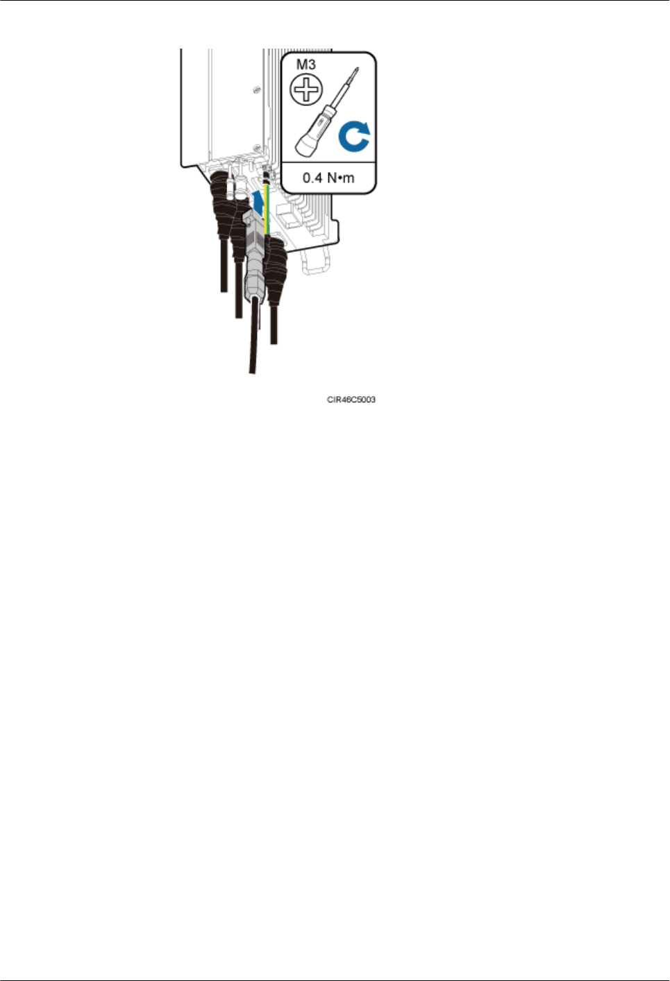
Figure 9-15 Installing an RRU AISG multi-wire cable
3. Use an M3 Phillips screwdriver to tighten the posts on both sides of the waterproof
DB9 connector to 0.4 N·m (3.54 lbf·in.).
4. Connect the other end of the cable to the standard AISG male connector on the RCU.
5. Route the cables according to the instructions in 9.1 Cabling Requirements, and then
use cable ties to bind the cables.
6. Label the installed cables according to the instructions in Attaching an L-Shaped
Label.
lInstall an AISG multi-wire cable that is configured with an AISG extension cable.
1. Use an M3 flat-head screwdriver to loosen the screws on the dustproof cap on the RET
port and remove the dustproof cap.
2. Link the waterproofed DB9 connector at one end of the AISG multi-wire cable to the
RET port on the RRU bottom, and link the other end to the standard AISG male
connector of the AISG extension cable, as shown in Figure 9-16.
RRU3260
Installation Guide 9 Installing RRU Cables
Issue () Huawei Proprietary and Confidential
Copyright © Huawei Technologies Co., Ltd.
108
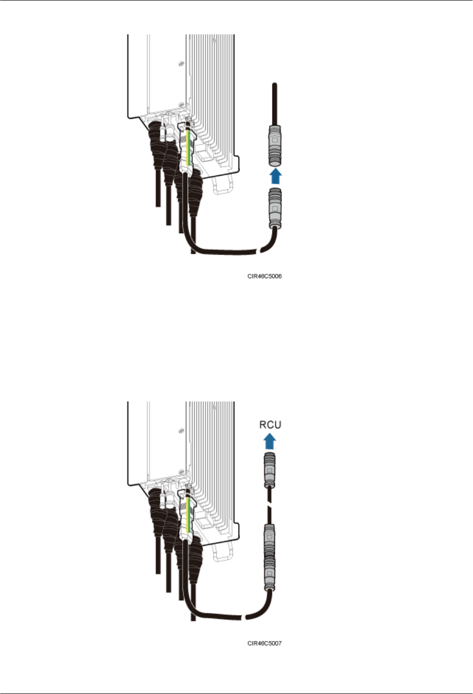
Figure 9-16 Installing an RRU AISG multi-wire cable
3. Use an M3 Phillips screwdriver to tighten the posts on both sides of the waterproof
DB9 connector to 0.4 N·m (3.54 lbf·in.).
4. Connect the other end of the AISG extension cable to the standard AISG male
connector on the RCU, as shown in Figure 9-17.
Figure 9-17 Installing an RRU AISG extension cable
RRU3260
Installation Guide 9 Installing RRU Cables
Issue () Huawei Proprietary and Confidential
Copyright © Huawei Technologies Co., Ltd.
109
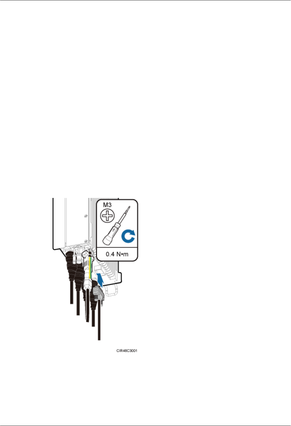
5. Route the cables according to the instructions in 9.1 Cabling Requirements, and then
use cable ties to bind the cables.
6. Label the installed cables according to the instructions in Attaching an L-Shaped
Label.
----End
9.8 Installing an RRU Alarm Cable
This section describes the procedure for installing an RRU alarm cable.
Procedure
Step 1 Use an M3 Phillips screwdriver to loosen the screws on the dustproof cap on the EXT_ALM
port and remove the dustproof cap.
Step 2 Connect the waterproof DB15 connector at one end of the RRU alarm cable to the EXT_ALM
port on the RRU, and connect the eight cord end terminals at the other end to external alarm
devices, as shown in Figure 9-18.
Figure 9-18 Installing an RRU alarm cable
Step 3 Use an M3 Phillips screwdriver to tighten the posts on both sides of the waterproof DB15 male
connector to 0.4 N·m (3.54 lbf·in.).
Step 4 Route the cables according to the instructions in 9.1 Cabling Requirements, and then use cable
ties to bind the cables.
RRU3260
Installation Guide 9 Installing RRU Cables
Issue () Huawei Proprietary and Confidential
Copyright © Huawei Technologies Co., Ltd.
110
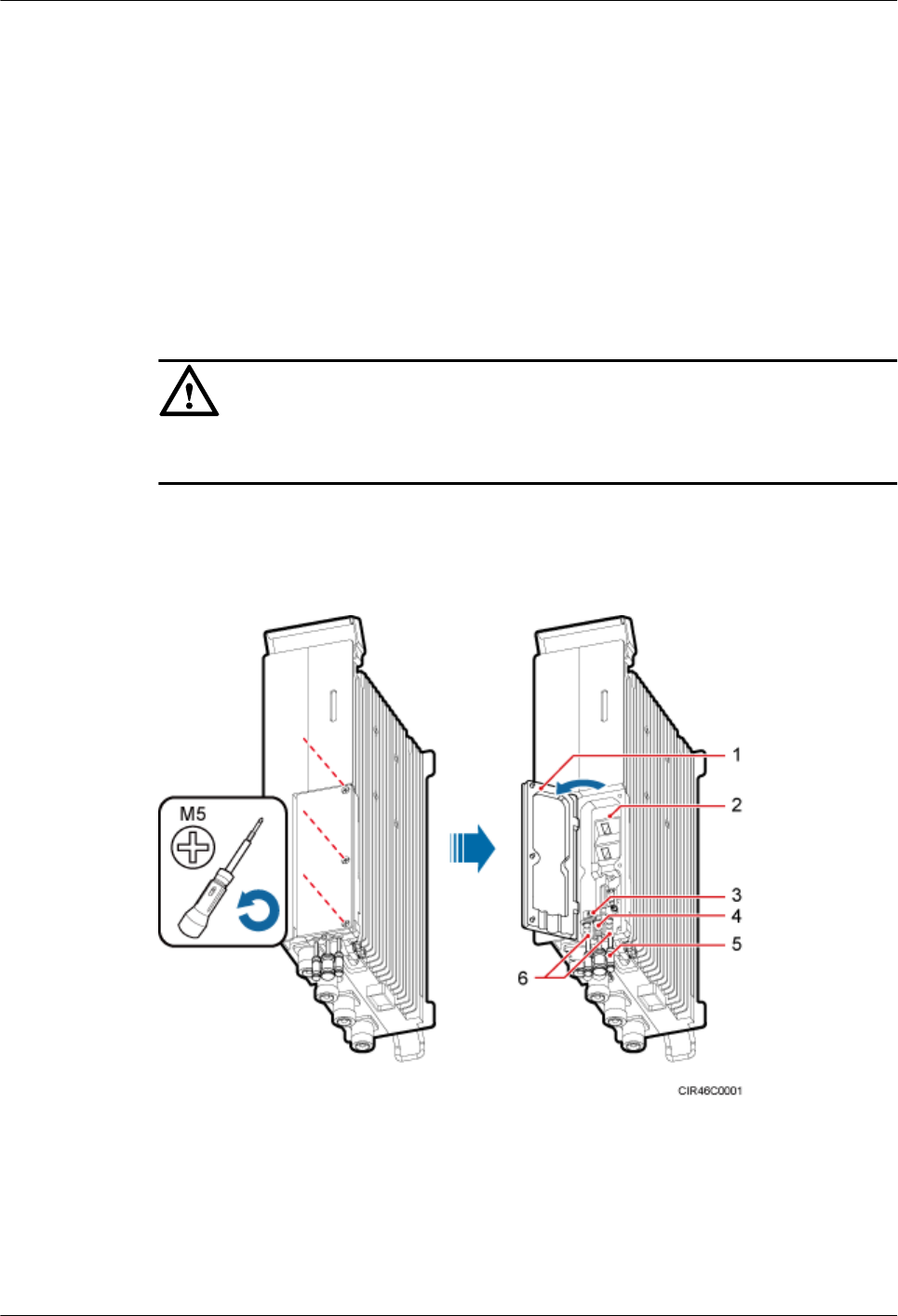
Step 5 Label the installed cables according to the instructions in Attaching an L-Shaped Label.
----End
9.9 Opening the Cover Plate of an RRU Cabling Cavity
This section describes the procedure for opening the cover plate of an RRU cabling cavity.
Procedure
Step 1 Wear ESD gloves.
CAUTION
Take proper ESD protection measures, for example, wear ESD gloves, to prevent electrostatic
damage to the boards, modules, or electronic components.
Step 2 Use an M5 Phillips screwdriver to loosen the three screws on the cover plate of the RRU cabling
cavity, and open the cover plate, as shown in Figure 9-19.
Figure 9-19 Opening the cover plate of the RRU cabling cavity
(1) Cover plate (2) Cabling cavity (3) Clip
(4) Cable trough for the power cable (5) Waterproof block (6) Cable trough for the fiber optic cable
Step 3 Loosen the screws on the clip, and open the clip, as shown Figure 9-20.
RRU3260
Installation Guide 9 Installing RRU Cables
Issue () Huawei Proprietary and Confidential
Copyright © Huawei Technologies Co., Ltd.
111
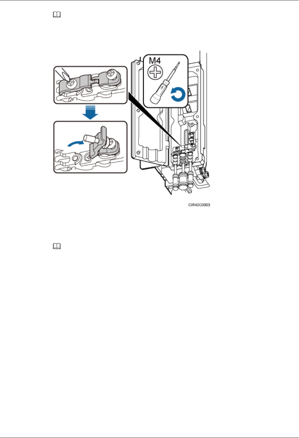
NOTE
Open the clip only for the associated cable.
Figure 9-20 Opening clips
Step 4 Remove the waterproof block.
NOTE
Remove only the waterproof blocks for the cables to be installed.
----End
9.10 Installing an RRU Power Cable
This section describes the procedure for installing an RRU power cable.
Prerequisites
lAn easy power receptacle (pressfit type) connector is added to the RRU power cable on
the RRU side. For details, see 12.1 Adding a Tool-Less Female Connector (Pressfit
Type) to the RRU Power Cable on the RRU Side.
lAdd a connector or OT terminals to the RRU power cable on the power device side. For
details, see the DBS3900 Installation Guide.
Context
There are four types of RRU power cables in terms of cross-sectional areas: 3.3 mm2 (0.005 in.
2) (12 AWG) and 5.3 mm2 (0.0082 in.2) (10 AWG) complying with North American standards,
4 mm2 (0.006 in.2) and 6 mm2 (0.0093 in.2) complying with European standards.
RRU3260
Installation Guide 9 Installing RRU Cables
Issue () Huawei Proprietary and Confidential
Copyright © Huawei Technologies Co., Ltd.
112
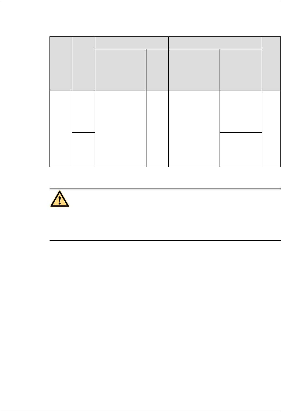
Table 9-2 describes the power cable connections.
Table 9-2 Power cable connections
Cabl
e
Powe
r
Devic
e
One End The Other End Re
mar
ks
Connector Instal
latio
n
Positi
on
Connector Installation
Position
RRU
power
cable
DCD
U-11
B
Tool-less female
connector
(pressfit type)
Power
port
on an
RRU
Tool-less female
connector
(pressfit type)
One of the
LOAD0 to
LOAD5 ports
on the
DCDU-11B
Blac
k
EPU One of the
RRU0 to
RRU5 ports on
the EPU
WARNING
When installing the RRU power cable, connect the RRU power cable first to the RRU and then
to the power device. Operations in the reverse sequence may cause damage to the components
and injury of human bodies.
Procedure
Step 1 Connect the tool-less female connector (pressfit type) at one end of the RRU power cable to the
power supply socket on the RRU, as shown in Figure 9-21.
RRU3260
Installation Guide 9 Installing RRU Cables
Issue () Huawei Proprietary and Confidential
Copyright © Huawei Technologies Co., Ltd.
113
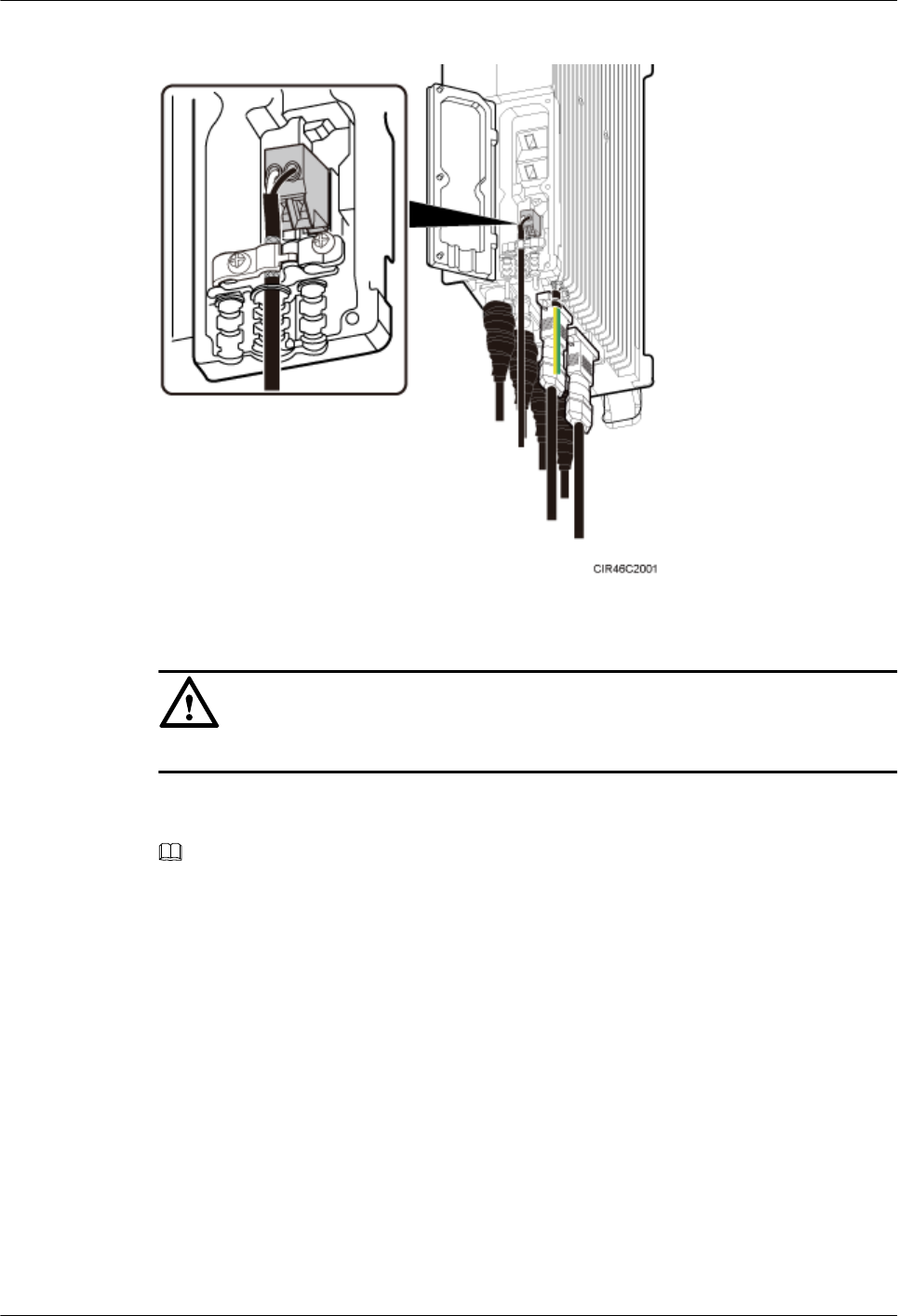
Figure 9-21 Installing an RRU power cable
CAUTION
Ensure that the exposed shield layer of the power cable is properly tightened using the clip.
Step 2 Connect the tool-less female connector (pressfit type) at the other end of the RRU power cable
to the corresponding position on the power device.
NOTE
lA DCDU-11B can supply power to a maximum of six RRUs. The RRU power cables are connected
to the LOAD0 to LOAD5 terminals on the DCDU-11B.
lAn EPU can supply power to a maximum of six RRUs. The RRU power cables are connected to the
RRU0 to RRU5 ports on the EPU.
lWhen the RRU power cable is connected to the EPU, the blue core wire in the tool-less female connector
(pressfit type) is connected to the left part of a port on the EPU, and the black/brown core wire is
connected to the right part of the port on the EPU.
Step 3 Route the cables according to the instructions in 9.1 Cabling Requirements, and then use cable
ties to bind the cables.
Step 4 Label the installed cables according to the instructions in Attaching a Cable-Tying Label.
----End
9.11 Installing a CPRI Fiber Optic Cable
This section describes the procedure for installing a CPRI fiber optic cable.
RRU3260
Installation Guide 9 Installing RRU Cables
Issue () Huawei Proprietary and Confidential
Copyright © Huawei Technologies Co., Ltd.
114
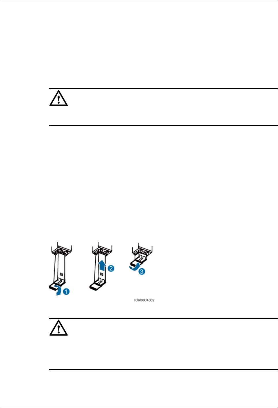
Prerequisites
Before the installation, single-mode optical modules can be distinguished from multi-mode
optical modules in either of the following ways:
lSM and MM labels on an optical module: SM indicates a single-mode optical module, and
MM indicates a multi-mode optical module.
lColor of the puller on an optical module: Blue indicates a single-mode optical module, and
black or gray indicates a multi-mode optical module.
CAUTION
The optical modules to be installed must match CPRI rates.
Context
lA CPRI fiber optic cable transmits CPRI signals between a BBU and an RRU.
lFor details about CPRI fiber optic cable connections, see section "CPRI Cable Connections"
in the BBU3900 Hardware Description or DBS3900 Hardware Description.
Procedure
Step 1 Lower the pullers of two optical modules, insert one optical module into the CPRI0 port on the
RRU and the other optical module into the CPRI port on the BBU, and raise the pullers, as shown
in Figure 9-22.
Figure 9-22 Installing an optical module
CAUTION
The performance of an optical module that is exposed to the air for more than 20 minutes may
be abnormal. Therefore, you must insert an fiber optic cable into an unpacked optical module
within 20 minutes.
Step 2 Connect the end labeled 1A and 1B of the fiber optic cable to the optical module on the RRU
side, as shown in Figure 9-23.
RRU3260
Installation Guide 9 Installing RRU Cables
Issue () Huawei Proprietary and Confidential
Copyright © Huawei Technologies Co., Ltd.
115
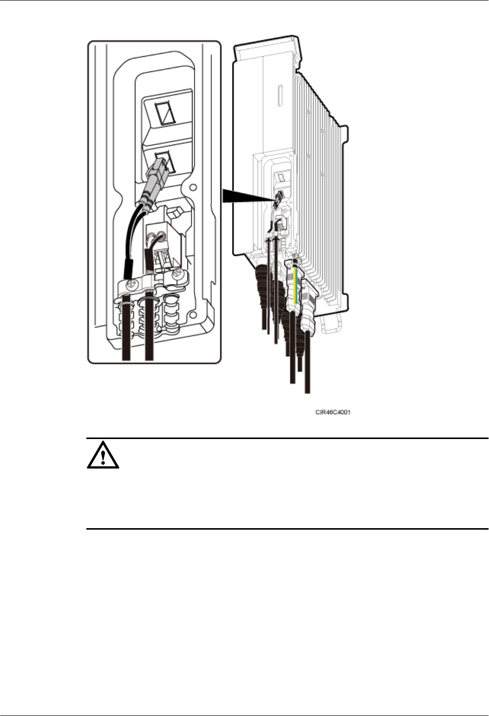
Figure 9-23 Installing a CPRI fiber optic cable
CAUTION
lTo avoid any damage to fiber optic cables, the cables connected to the RRU must be installed
according to the installation process. For details about the installation process, see 9.3
Installation Process.
Step 3 Connect the end labeled 2A and 2B of the fiber optic cable to the optical module on the BBU
side.
Step 4 Route the cables according to the instructions in 9.1 Cabling Requirements, and then use cable
ties to bind the cables.
Step 5 Label the installed cables according to the instructions in Attaching an L-Shaped Label.
----End
9.12 Closing the Cover Plate of an RRU Cabling Cavity
This section describes the procedure for closing the cover plate of an RRU cabling cavity.
RRU3260
Installation Guide 9 Installing RRU Cables
Issue () Huawei Proprietary and Confidential
Copyright © Huawei Technologies Co., Ltd.
116
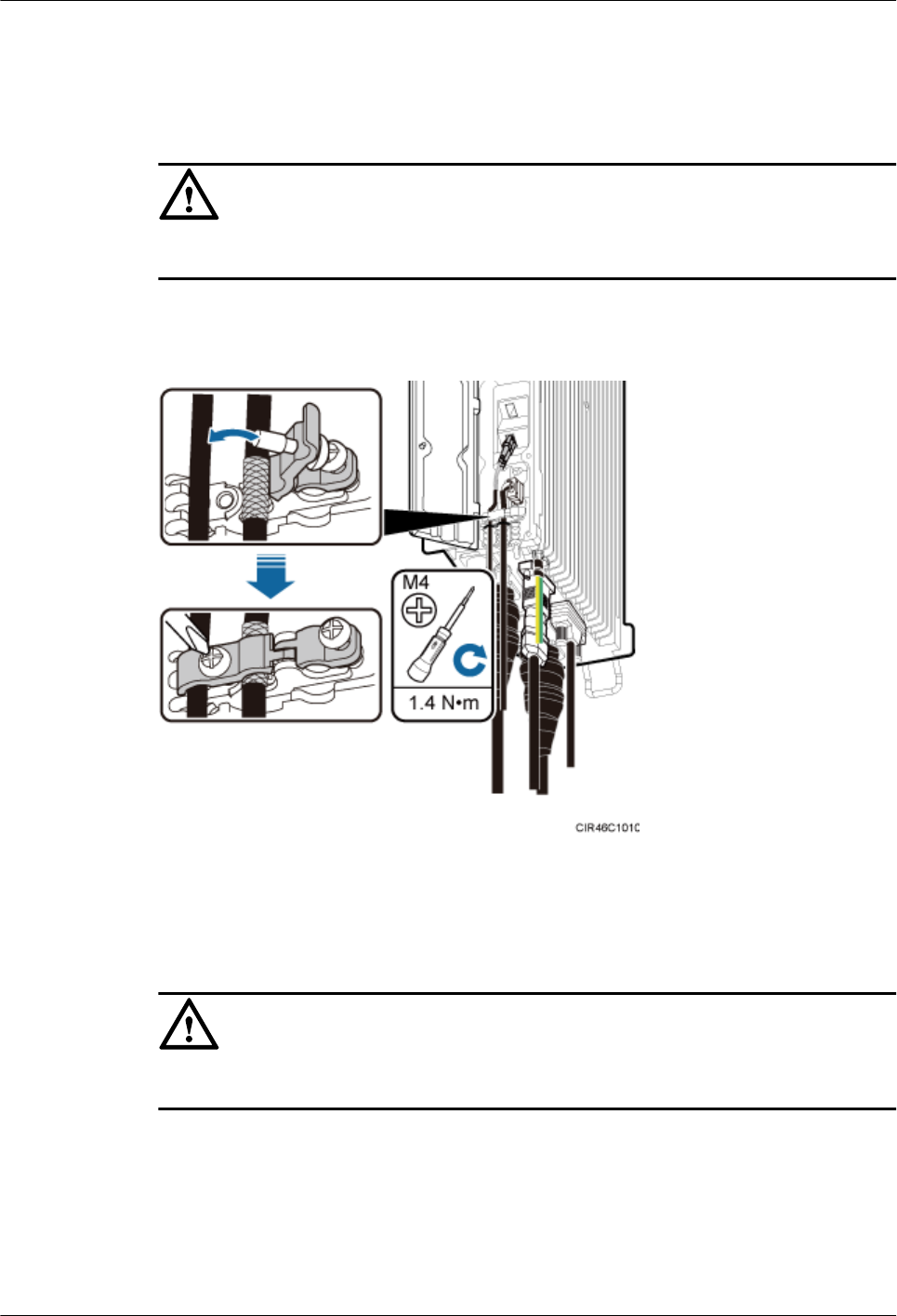
Procedure
Step 1 Close the clips for the installed cables. Use a torque screwdriver to tighten the screws on each
clip to 1.4 N·m (12.39 lbf·in.), as shown in Figure 9-24.
CAUTION
Ensure that the exposed shield layer of the power cable is properly tightened using the clip.
Figure 9-24 Closing clips
Step 2 Insert waterproof blocks into vacant cable troughs in the cabling cavity, as shown in Figure
9-25.
CAUTION
Ensure that cables and waterproof blocks are properly inserted into troughs.
RRU3260
Installation Guide 9 Installing RRU Cables
Issue () Huawei Proprietary and Confidential
Copyright © Huawei Technologies Co., Ltd.
117
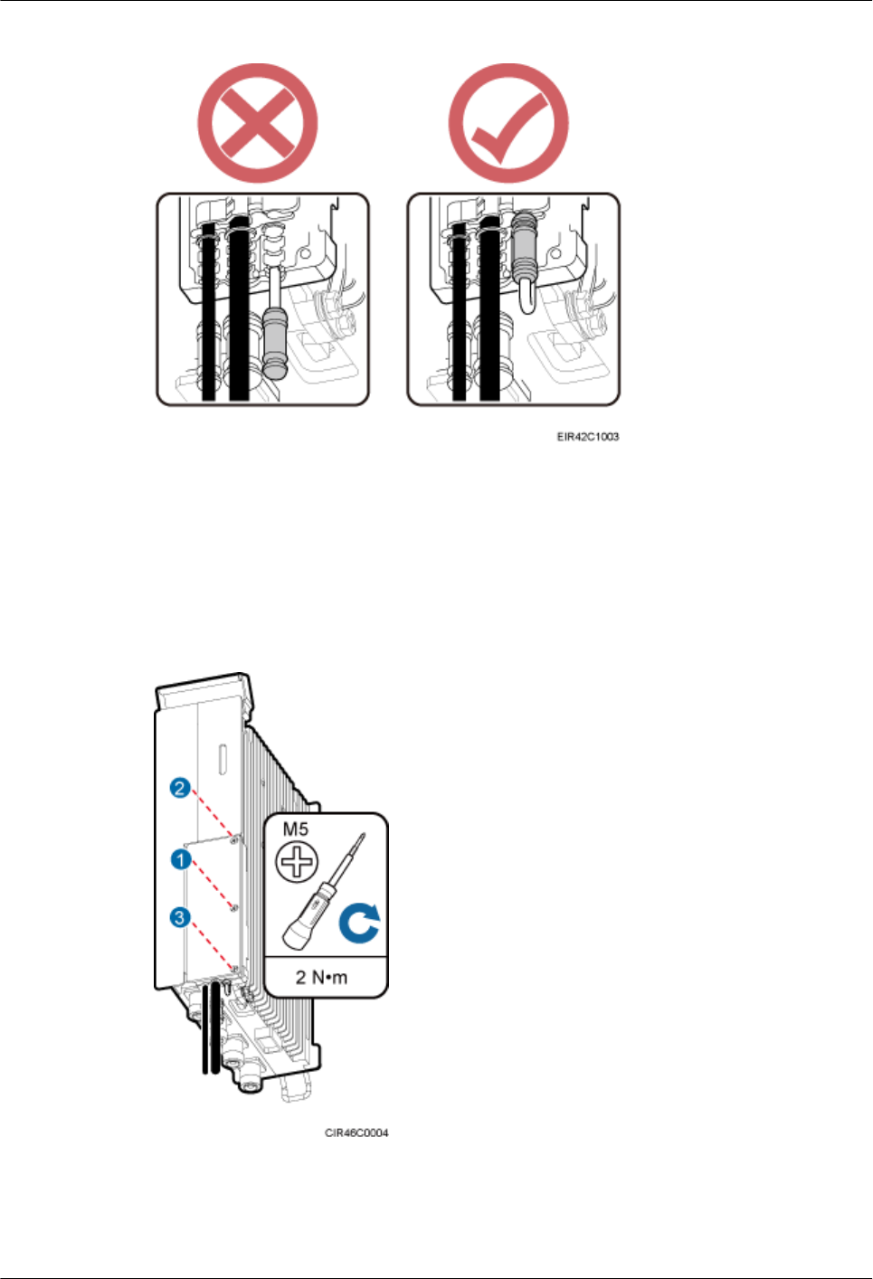
Figure 9-25 Correct placement of waterproof blocks
Step 3 Close the cover plate of the RRU cabling cavity. Use an M5 torque screwdriver to partially
tighten the screws on the cover plate in the sequence shown in Figure 9-26. Then tighten the
screws to 2 N·m (17.7 lbf·in.) in the same sequence.
Figure 9-26 Closing the cover plate of an RRU cabling cavity
RRU3260
Installation Guide 9 Installing RRU Cables
Issue () Huawei Proprietary and Confidential
Copyright © Huawei Technologies Co., Ltd.
118

Step 4 Take off the ESD gloves, and pack up all the tools.
----End
RRU3260
Installation Guide 9 Installing RRU Cables
Issue () Huawei Proprietary and Confidential
Copyright © Huawei Technologies Co., Ltd.
119
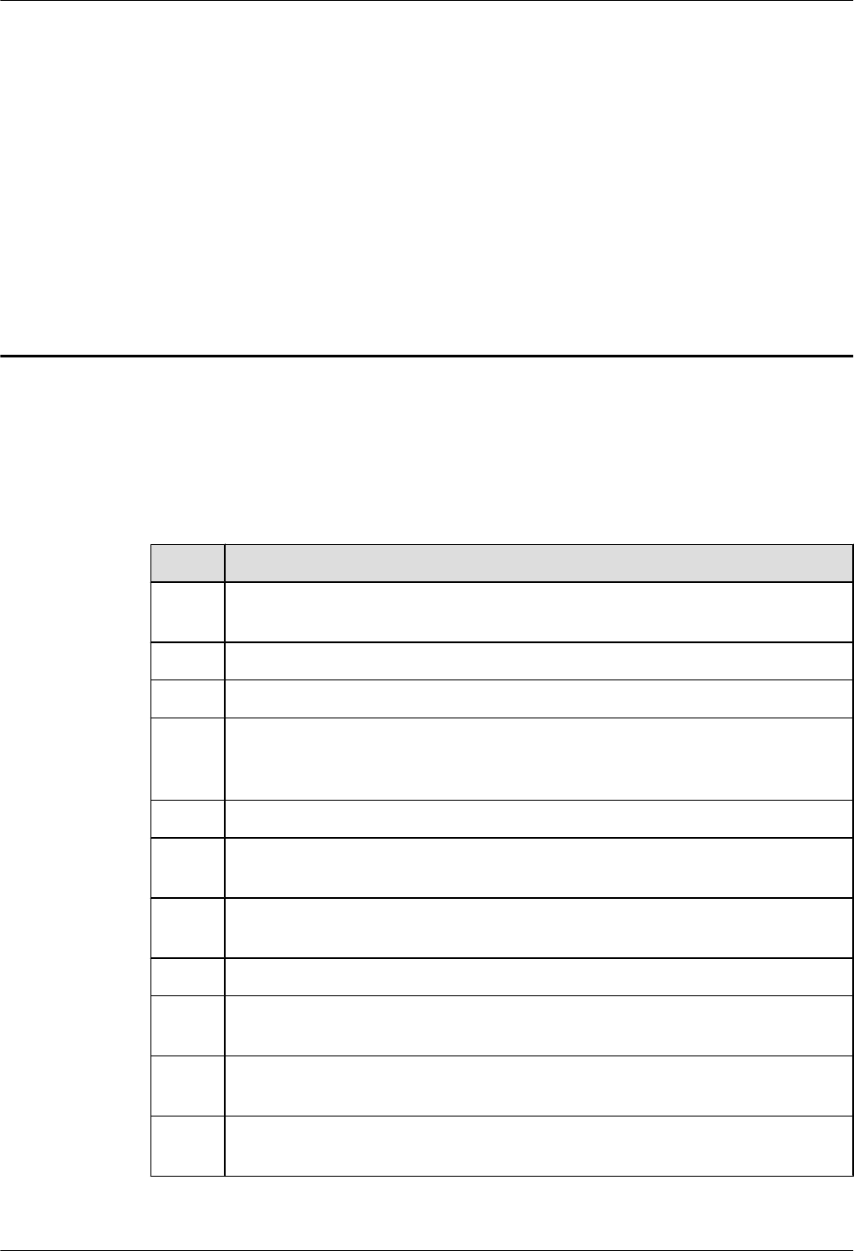
10 Checking the RRU Hardware
Installation
After an RRU is installed, check the hardware installation.
Table 10-1 provides the checklist for the RRU hardware installation.
Table 10-1 Checklist for the RRU hardware installation
SN Item
1The position for each device conforms to the engineering drawing and meets the
space requirement. Sufficient space is reserved for equipment maintenance.
2 The RRU is securely installed.
3 The cover plate is securely installed on the RRU cabling cavity.
4 Waterproof blocks are securely installed in vacant cable troughs of the RRU cabling
cavity, and the cover plate for the cabling cavity is securely installed. In addition,
vacant RF ports are covered with dustproof caps and the caps are tightened.
5 There are no connectors or joints on each power cable or PGND cable.
6 The terminals at two ends of each power cable or PGND cable are securely soldered
or crimped.
7 None of power cables and PGND cables can be short-circuited or reversely
connected. In addition, these cables are not damaged or broken.
8 Power cables and PGND cables are separately bound from other cables.
9 The protection grounding of the RRU and the surge protection grounding of the
building share one group of ground conductors.
10 The connectors of each signal cable are intact and securely linked, and these cables
are not damaged or broken.
11 Labels are correct, legible, and complete at both ends of each cable, feeder, and
jumper.
RRU3260
Installation Guide 10 Checking the RRU Hardware Installation
Issue () Huawei Proprietary and Confidential
Copyright © Huawei Technologies Co., Ltd.
120
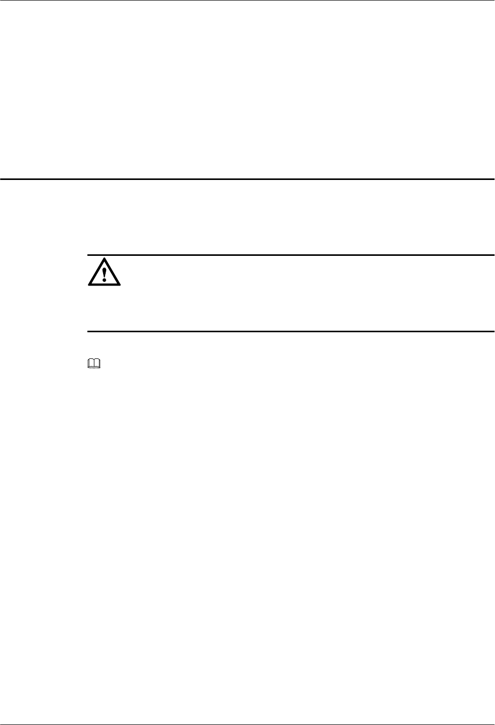
11 Powering On an RRU
After all the devices are installed, check the power-on status of an RRU.
CAUTION
After you unpack an RRU, you must power on it within 24 hours. If you power off the RRU for
maintenance, you must restore power to the RRU within 24 hours.
Figure 11-1 shows the RRU power-on check process.
NOTE
For details about how to power on an RRU, see Powering On an RRU. For details about how to power off
an RRU, see section "Powering-Off the RRU" in RRU Maintenance Guide.
RRU3260
Installation Guide 11 Powering On an RRU
Issue () Huawei Proprietary and Confidential
Copyright © Huawei Technologies Co., Ltd.
121
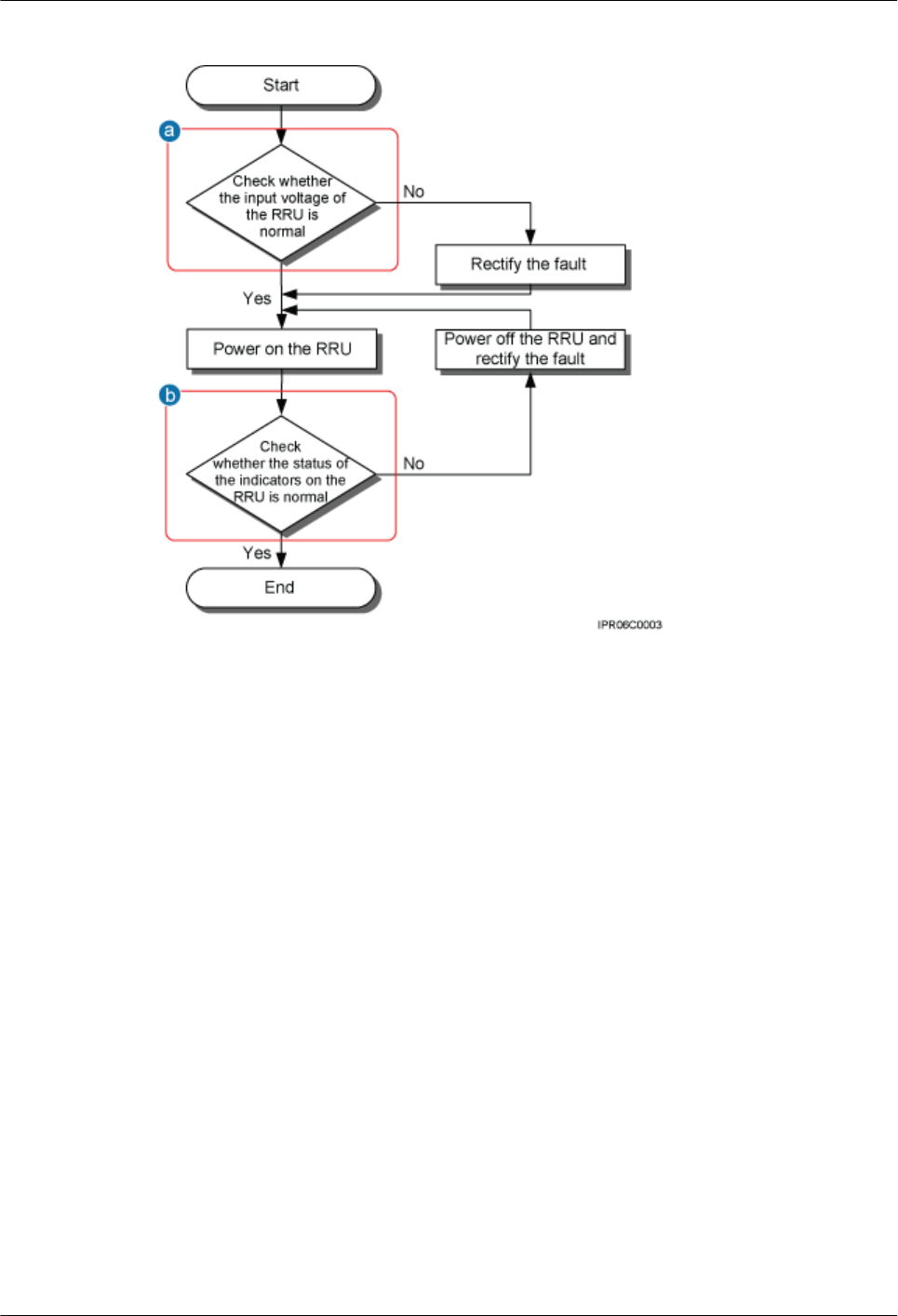
Figure 11-1 RRU power-on check process
(a) The normal input voltage of an RRU is -48 V DC. The voltage of the external power supply should range
from -36 V DC to -57 V DC.
(b) The RUN indicator on the RRU is on for 1s and off for 1s. The ALM indicator is steady off.
RRU3260
Installation Guide 11 Powering On an RRU
Issue () Huawei Proprietary and Confidential
Copyright © Huawei Technologies Co., Ltd.
122

12 Appendix
About This Chapter
This section describes the procedure for adding an easy power receptacle (pressfit type)
connector.
12.1 Adding a Tool-Less Female Connector (Pressfit Type) to the RRU Power Cable on the
RRU Side
This section describes the procedure for adding a tool-less female connector (pressfit type) to
the RRU power cable on the RRU side.
RRU3260
Installation Guide 12 Appendix
Issue () Huawei Proprietary and Confidential
Copyright © Huawei Technologies Co., Ltd.
123
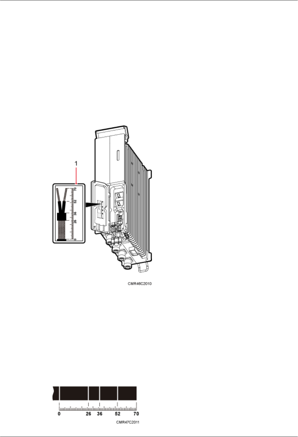
12.1 Adding a Tool-Less Female Connector (Pressfit Type)
to the RRU Power Cable on the RRU Side
This section describes the procedure for adding a tool-less female connector (pressfit type) to
the RRU power cable on the RRU side.
Context
Figure 12-1 shows the cable diagram on labels.
Figure 12-1 Cable diagram on labels
(1) Cable diagram on labels
Procedure
Step 1 Determine the length of the power cable for different operations based on the labels, as shown
in Figure 12-2.
Figure 12-2 Determining the length of the power cable
RRU3260
Installation Guide 12 Appendix
Issue () Huawei Proprietary and Confidential
Copyright © Huawei Technologies Co., Ltd.
124
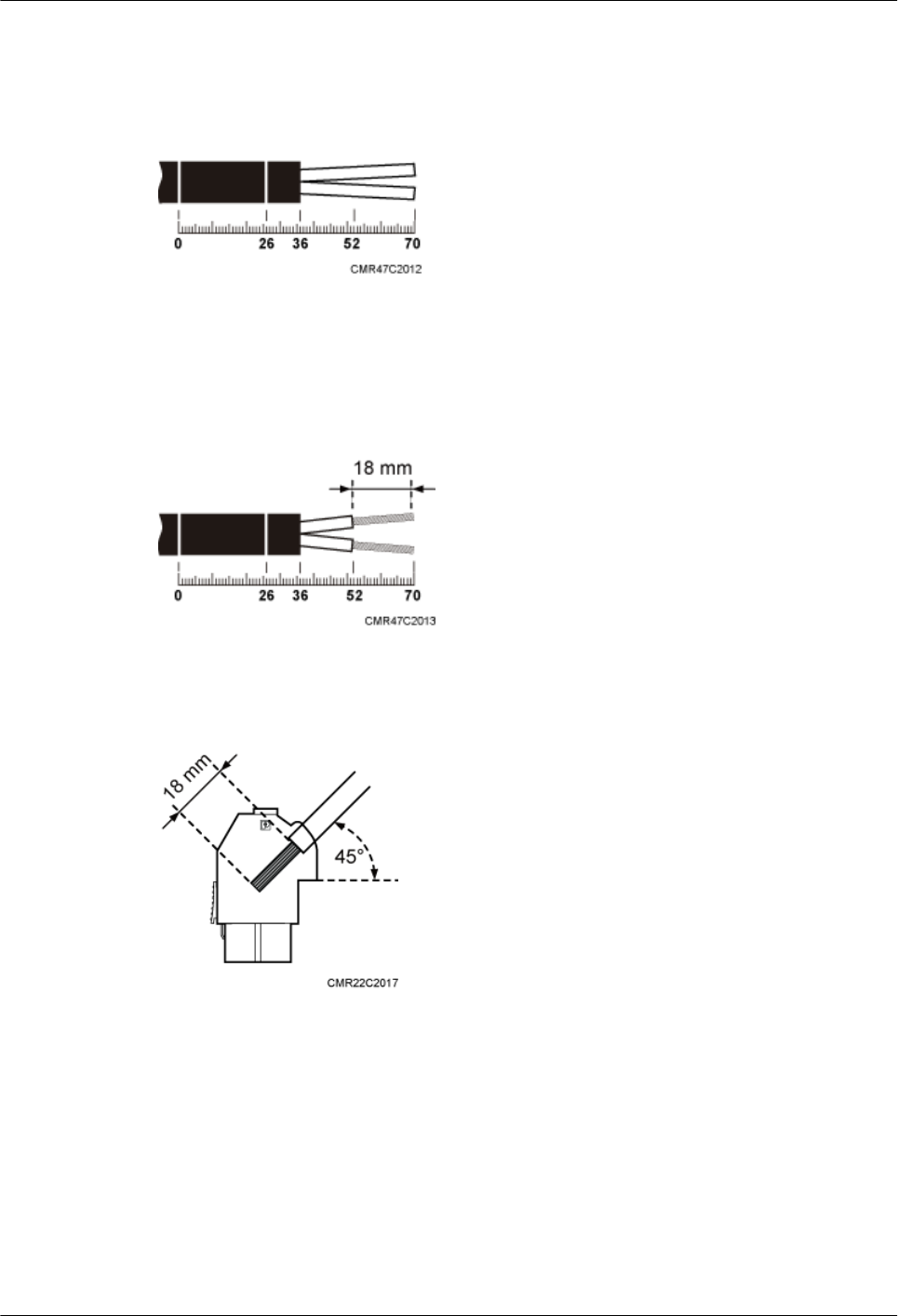
Step 2 Strip the specified length of the sheath off the power cable, as shown in Figure 12-3.
Figure 12-3 Stripping the specified length of sheath
Step 3 Strip a specified length of sheath off each core wire. The length must be consistent with the
length of the notch in the tool-less female connector (pressfit type), as shown in Figure 12-4.
Figure 12-4 Stripping the sheath off each core wire
Figure 12-5 Matched length
Step 4 Add a tool-less female connector (pressfit type) to two core wires.
1. Tighten the screws using a Phillips screwdriver, as shown in Figure 12-6.
RRU3260
Installation Guide 12 Appendix
Issue () Huawei Proprietary and Confidential
Copyright © Huawei Technologies Co., Ltd.
125
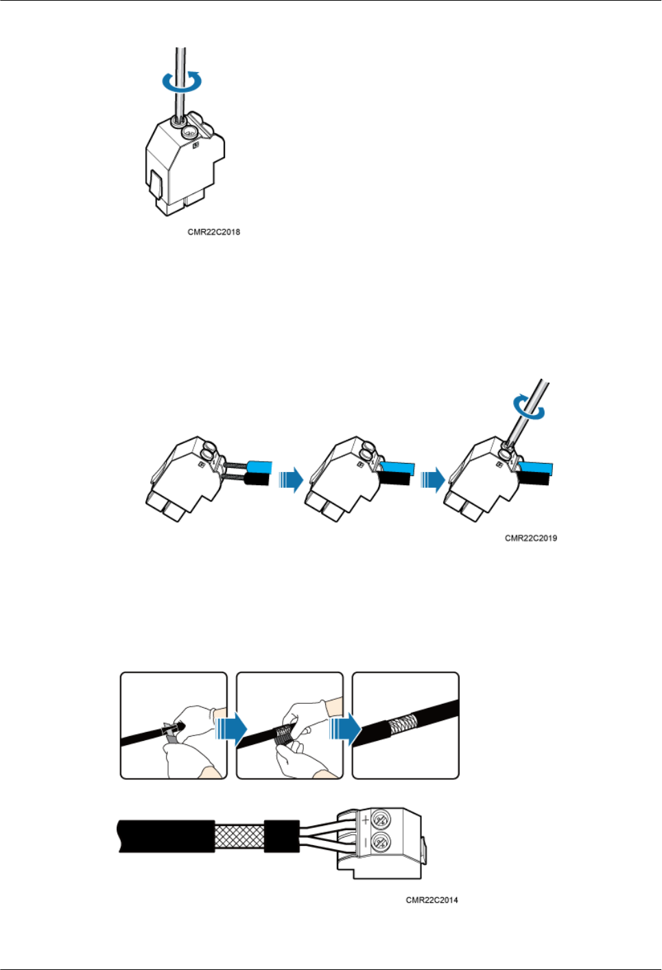
Figure 12-6 Tightening screws
2. Connect the blue core wire labeled NEG(-) to the - port and the black/brown core wire
labeled RTN(+) to the + port on the tool-less female connector (pressfit type), and then
tighten the screws using a Phillips screwdriver, as shown in Figure 12-7.
Figure 12-7 Adding a tool-less female connector (pressfit type) to two core wires
Step 5 Strip the specified length of the sheath off the power cable to expose the intact shield layer, as
shown in Figure 12-8.
Figure 12-8 Stripping the sheath off the power cable
RRU3260
Installation Guide 12 Appendix
Issue () Huawei Proprietary and Confidential
Copyright © Huawei Technologies Co., Ltd.
126
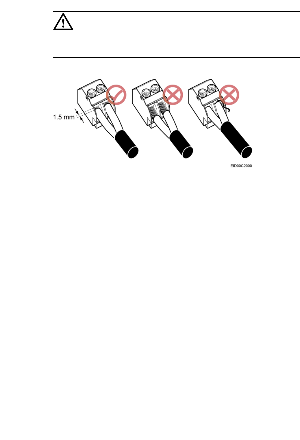
CAUTION
Each core wire is exposed outside the tool-less female connector (pressfit type) for 1.5 mm
(0.059 [in.]), as shown in Figure 12-9.
Figure 12-9 Inserting core wires into the tool-less female connector (pressfit type)
----End
RRU3260
Installation Guide 12 Appendix
Issue () Huawei Proprietary and Confidential
Copyright © Huawei Technologies Co., Ltd.
127