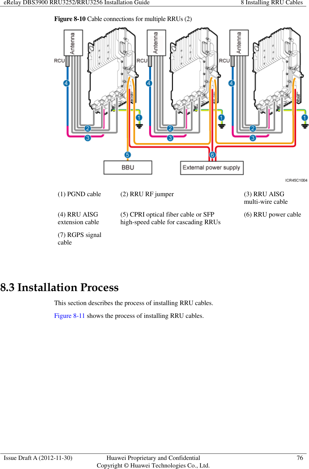
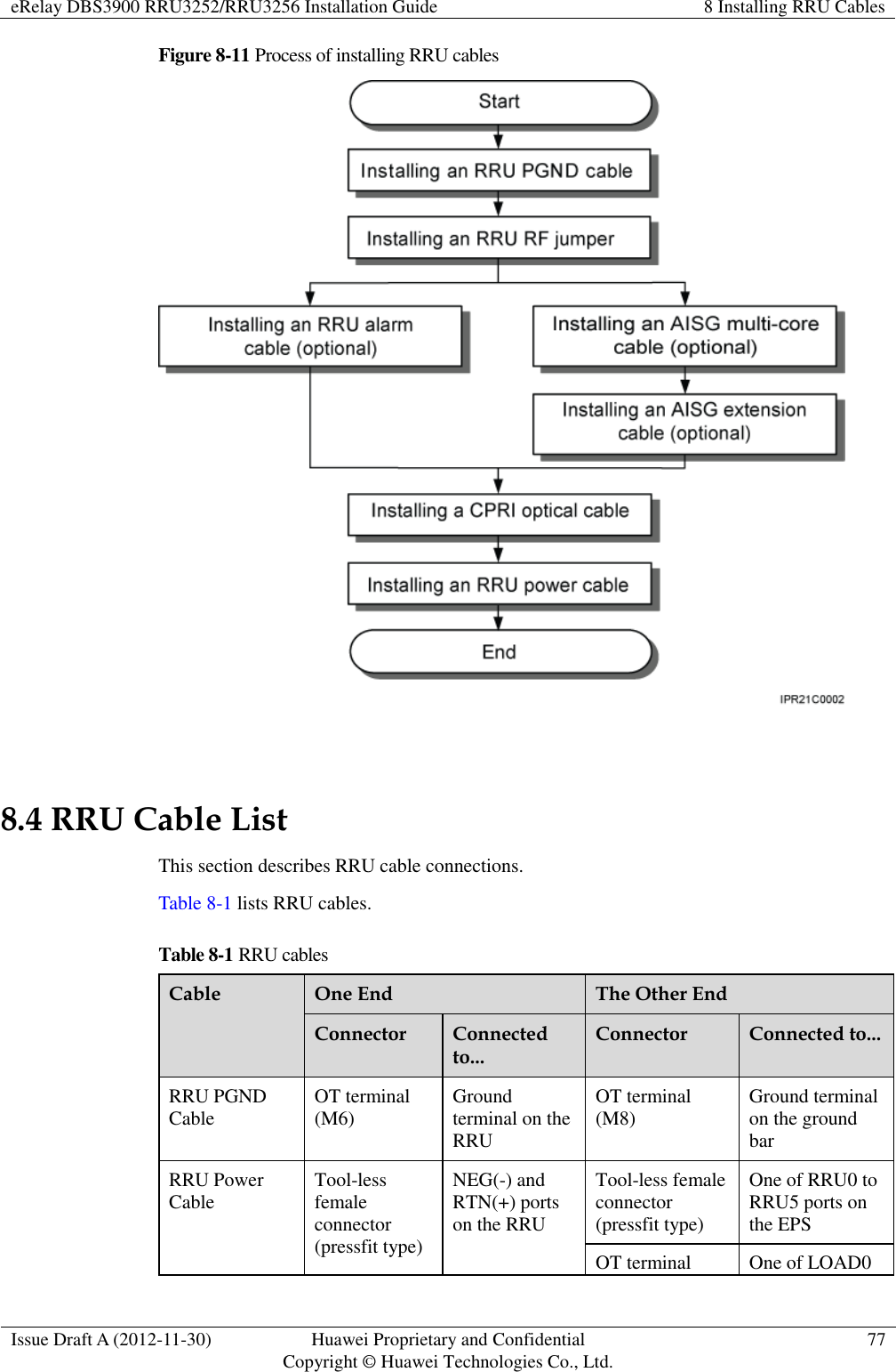
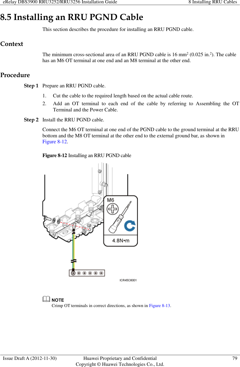
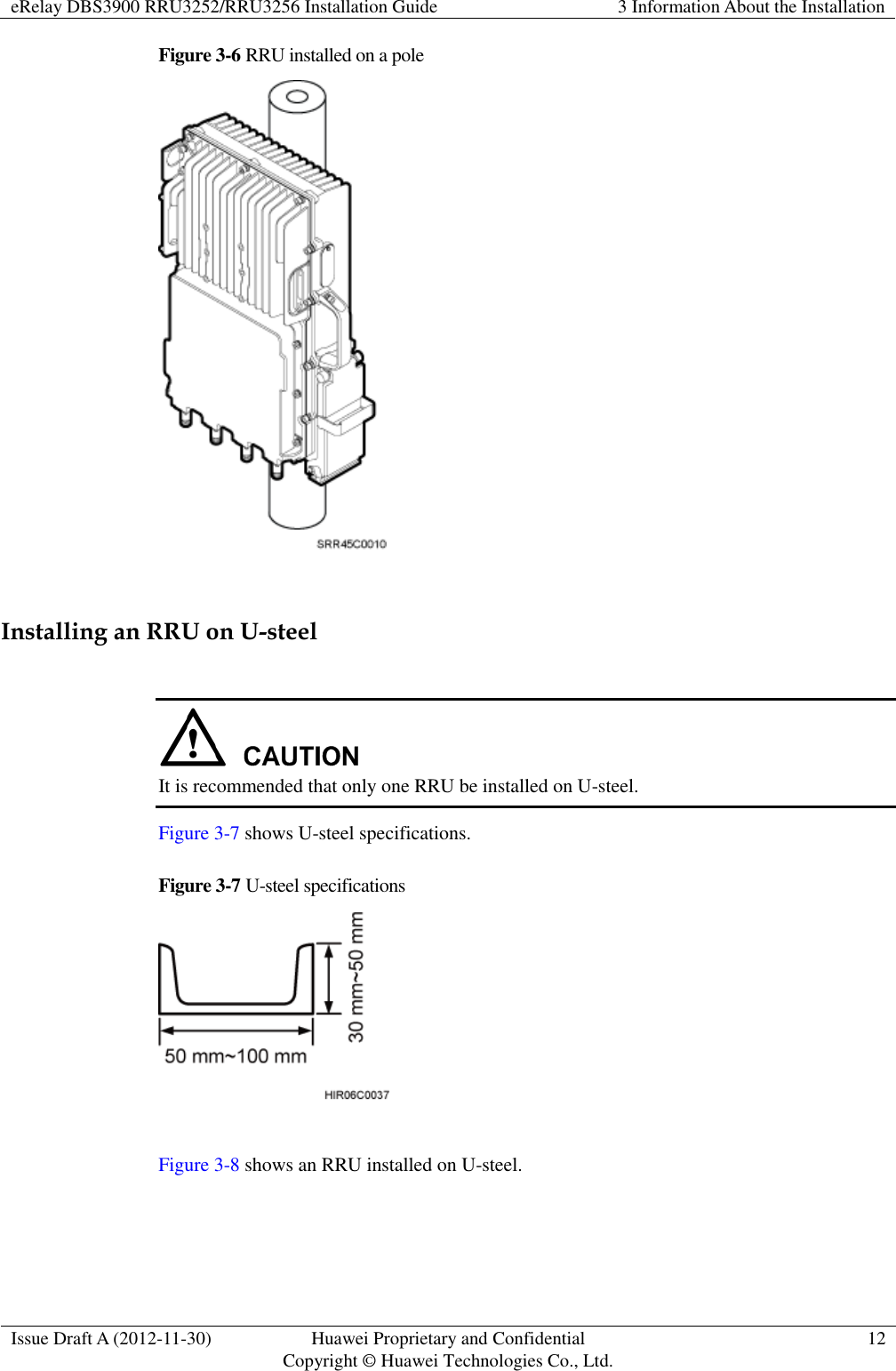
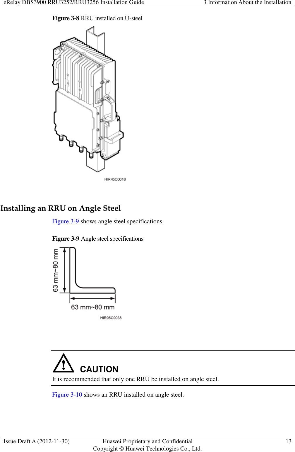
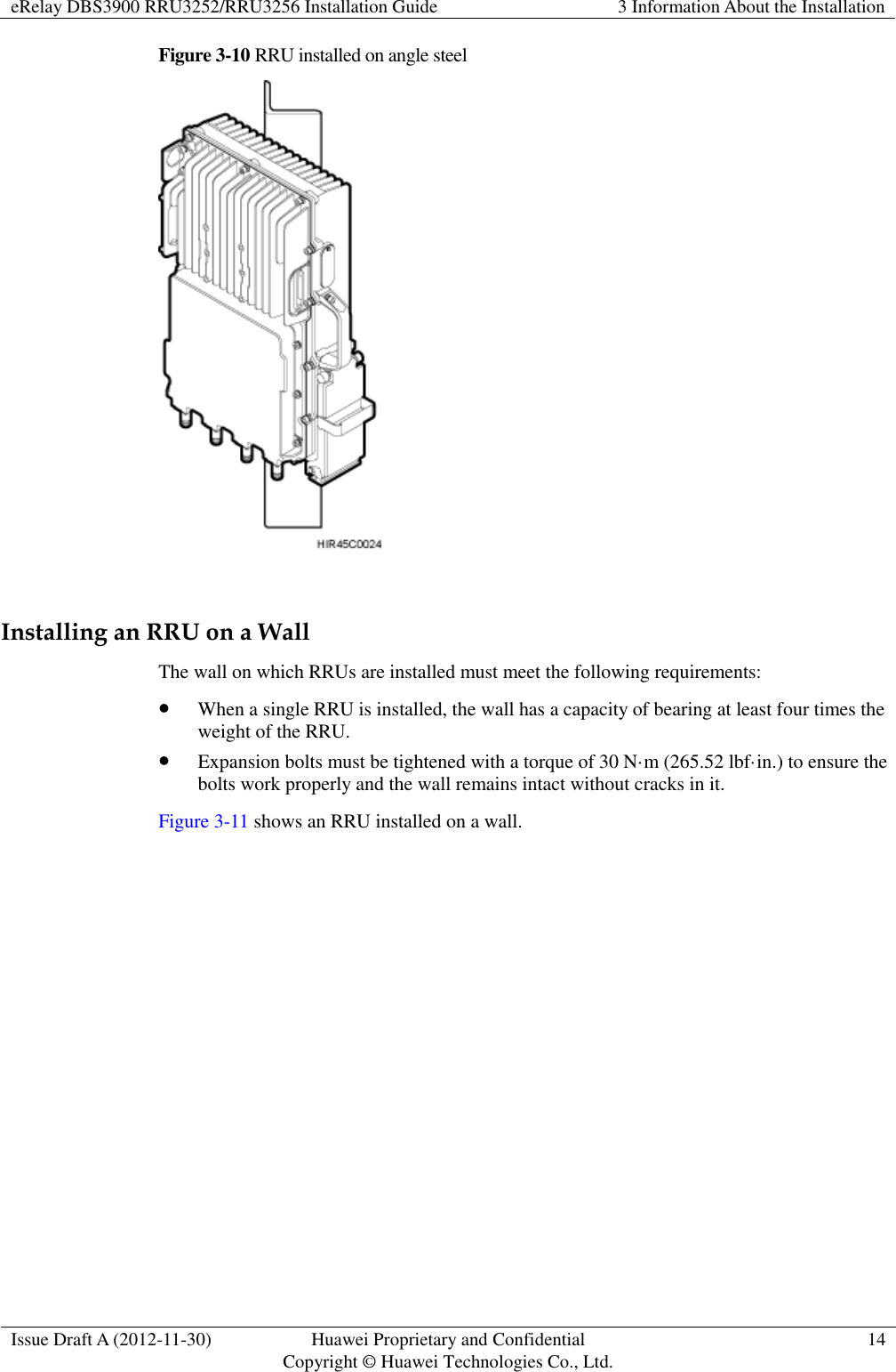
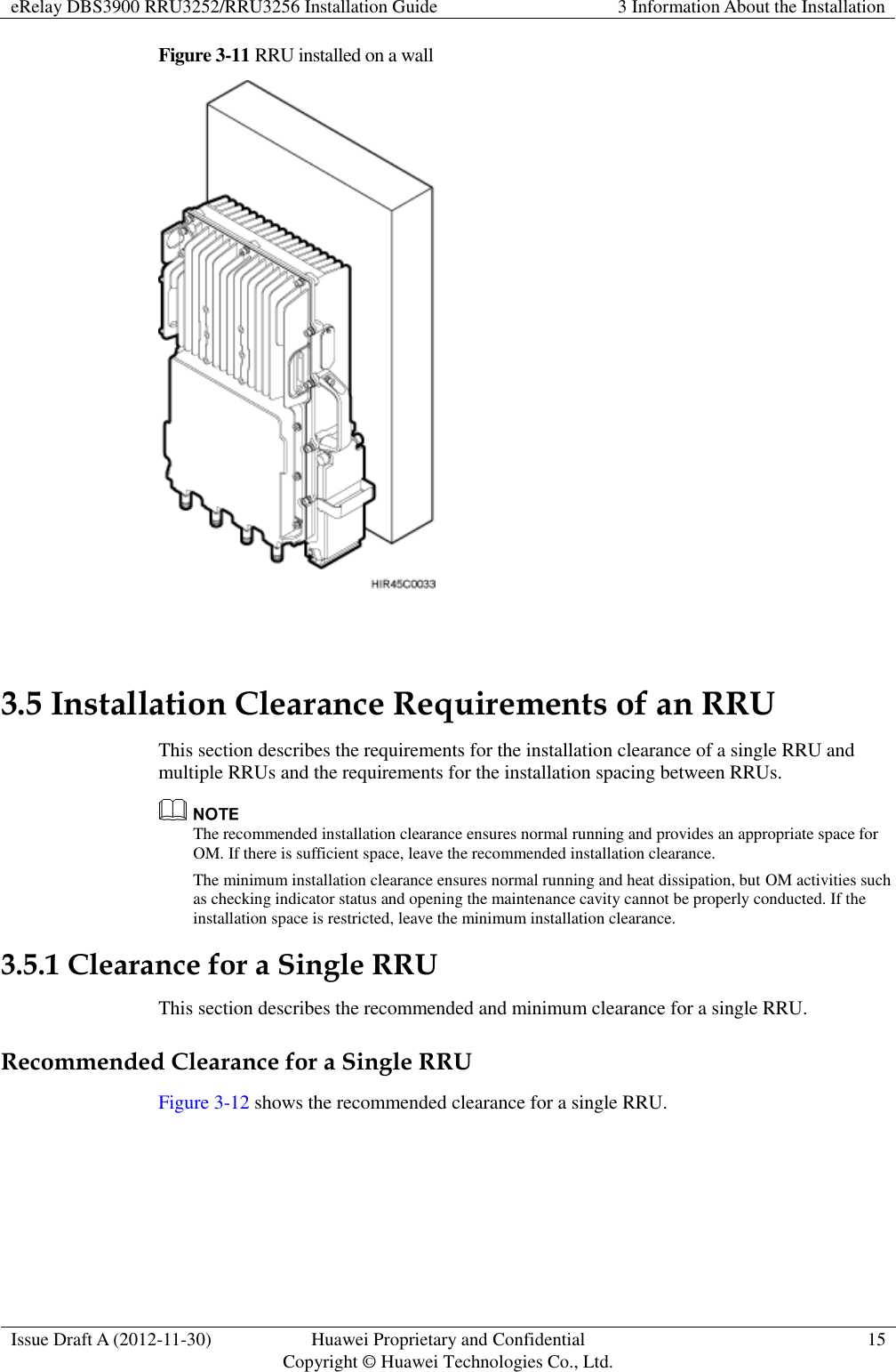
Huawei Technologies RRU3276 Remote Radio Unit User Manual RRU3252 RRU3256 Installation Guide
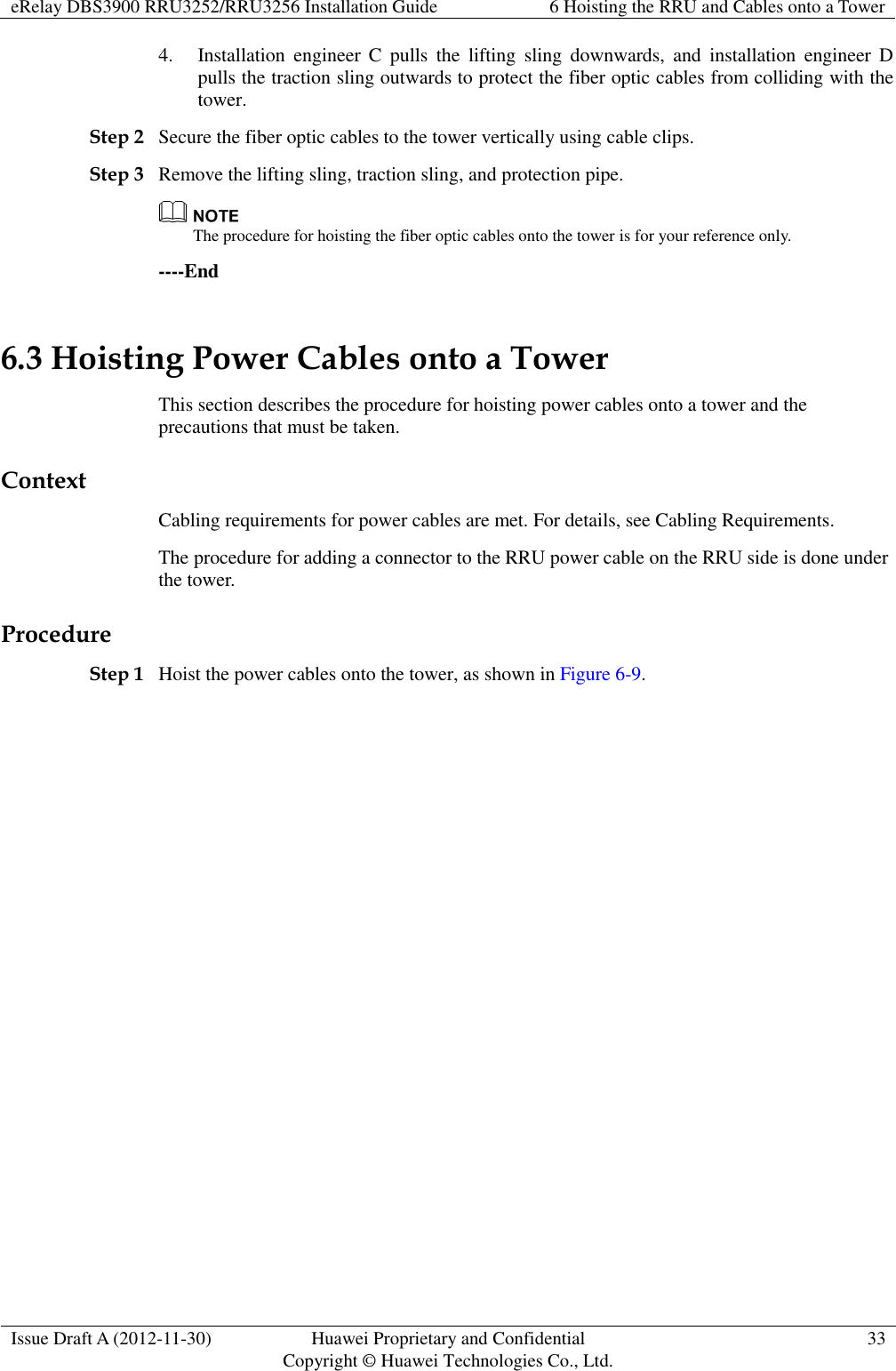
Huawei Technologies Co.,Ltd Remote Radio Unit RRU3252 RRU3256 Installation Guide
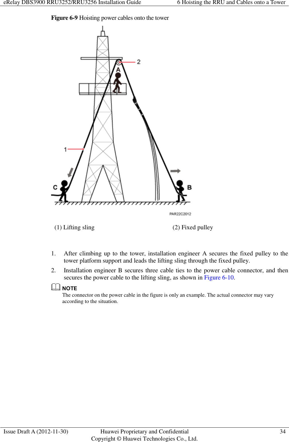
Contents
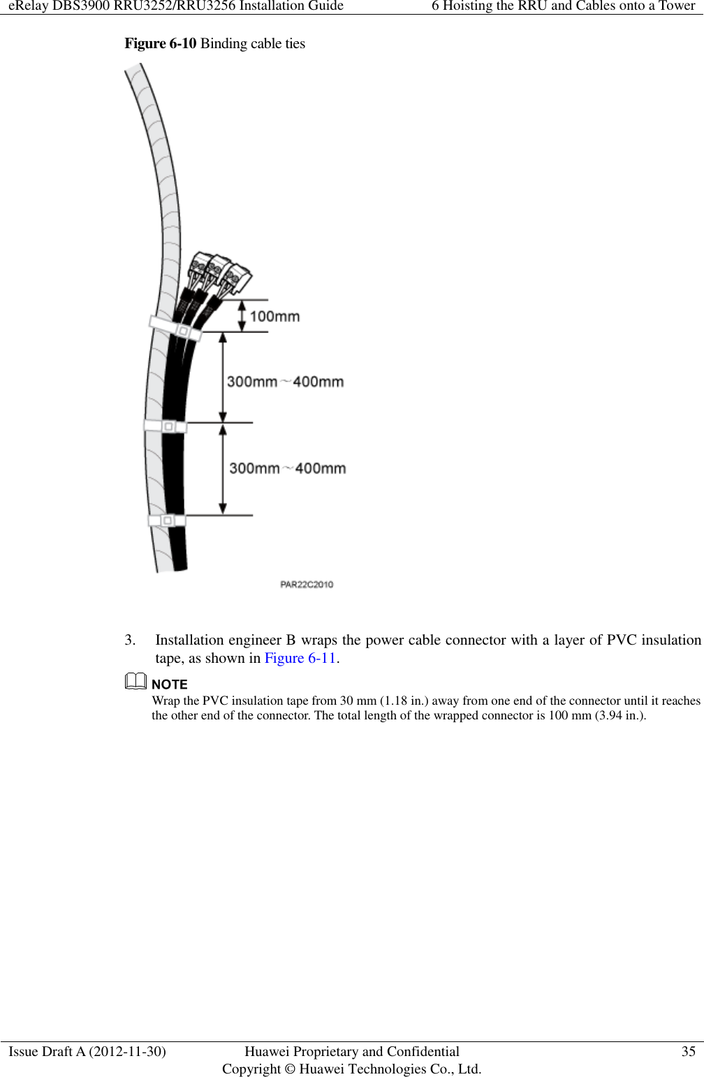
- 1. Compliance and Safety Manual
- 2. Installation Guide 2
- 3. Installation Guide
Installation Guide 2
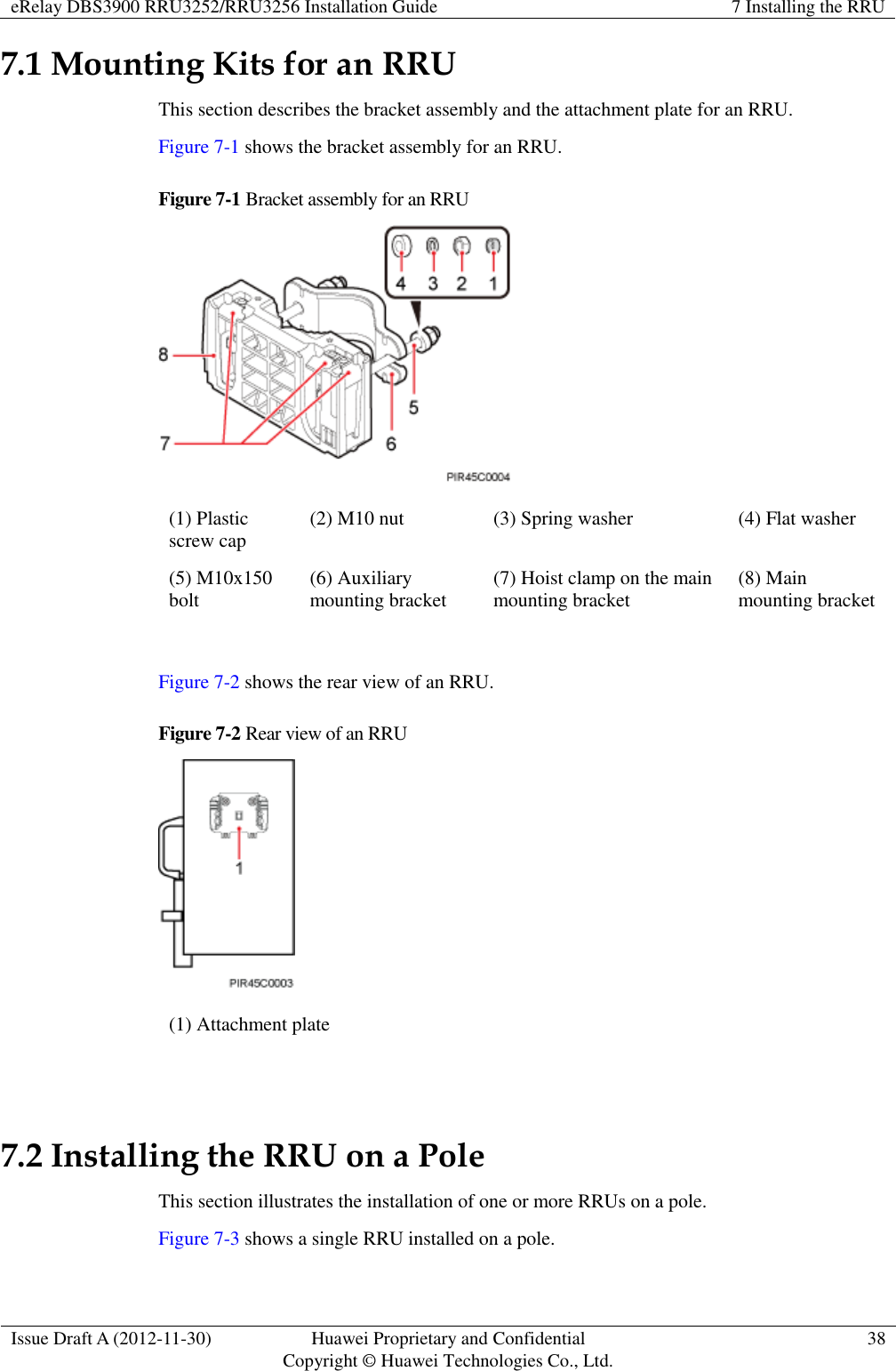
![DBS3900 LTE TDD RRU3252/RRU3256 Installation Guide About This Document Issue Draft A (2012-11-30) Huawei Proprietary and Confidential Copyright © Huawei Technologies Co., Ltd. iv General Conventions Convention Description Times New Roman Normal paragraphs are in Times New Roman. Boldface Names of files, directories, folders, and users are in boldface. For example, log in as user root. Italic Book titles are in italics. Courier New Terminal display is in Courier New. Command Conventions Convention Description Boldface The keywords of a command line are in boldface. Italic Command arguments are in italics. [ ] Items (keywords or arguments) in square brackets [ ] are optional. { x | y | ... } Alternative items are grouped in braces and separated by vertical bars. One is selected. [ x | y | ... ] Optional alternative items are grouped in square brackets and separated by vertical bars. One or none is selected. { x | y | ... } * Alternative items are grouped in braces and separated by vertical bars. A minimum of one or a maximum of all can be selected. GUI Conventions Convention Description Boldface Buttons, menus, parameters, tabs, windows, and dialog titles are in boldface. For example, click OK. > Multi-level menus are in boldface and separated by the ">" signs. For example, choose File > Create > Folder. Keyboard Operation Format Description Key Press the key. For example, press Enter and press Tab.](https://usermanual.wiki/Huawei-Technologies/RRU3276.Installation-Guide-2/User-Guide-3292164-Page-5.png)
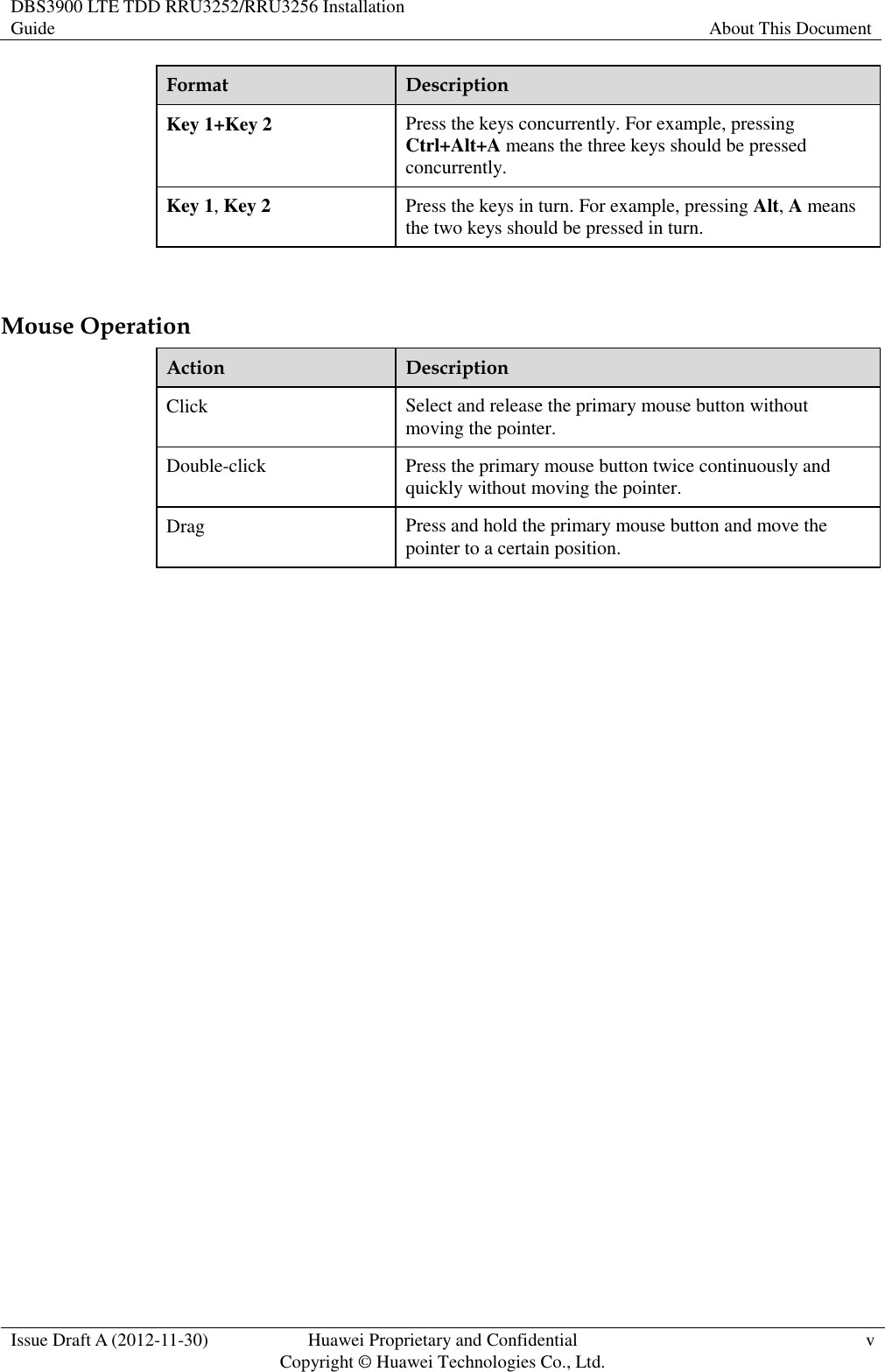
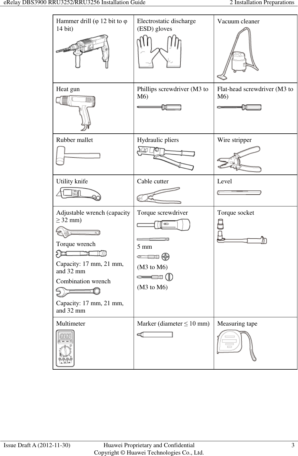
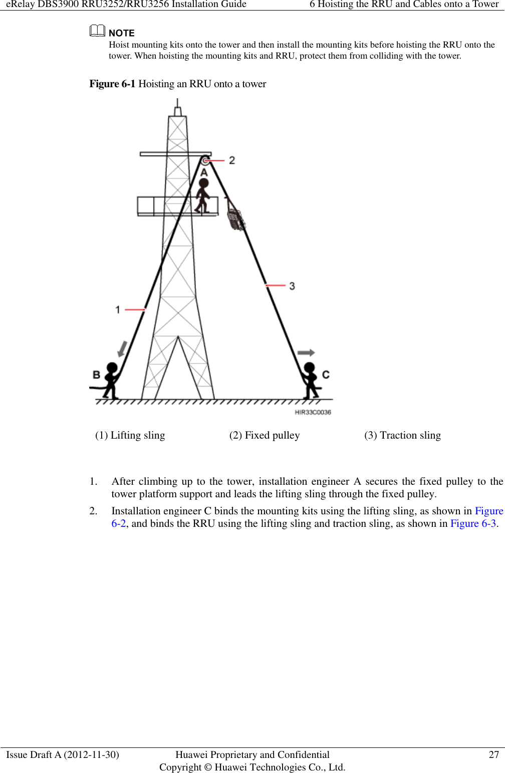
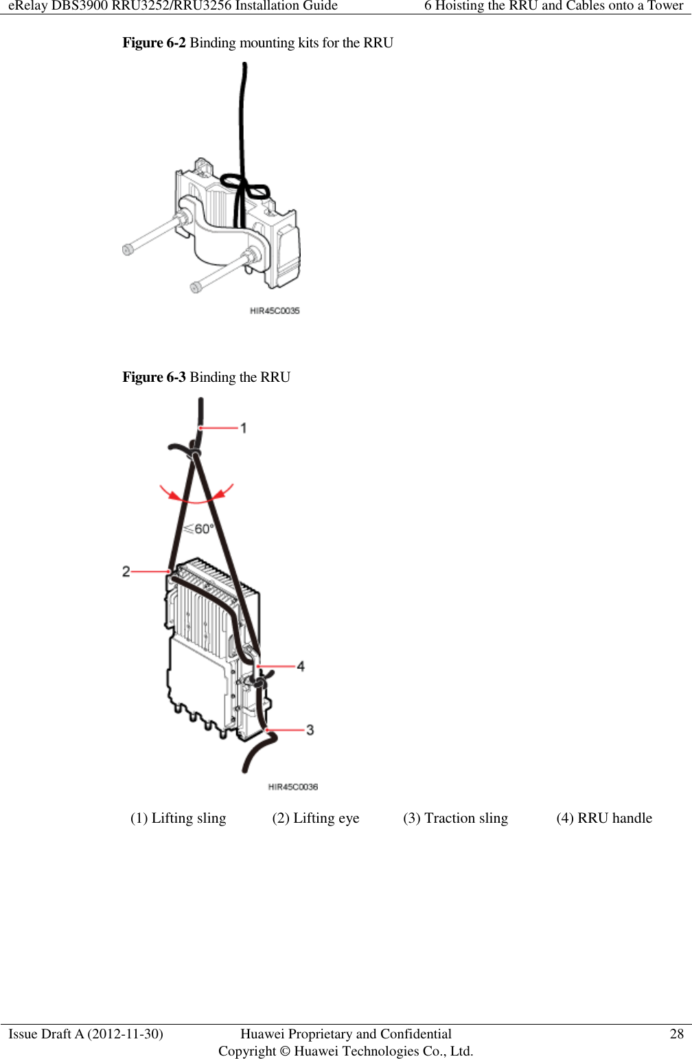
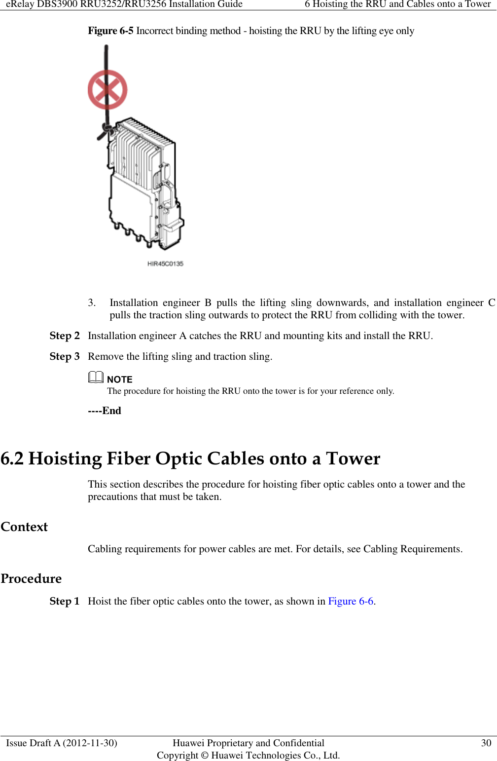
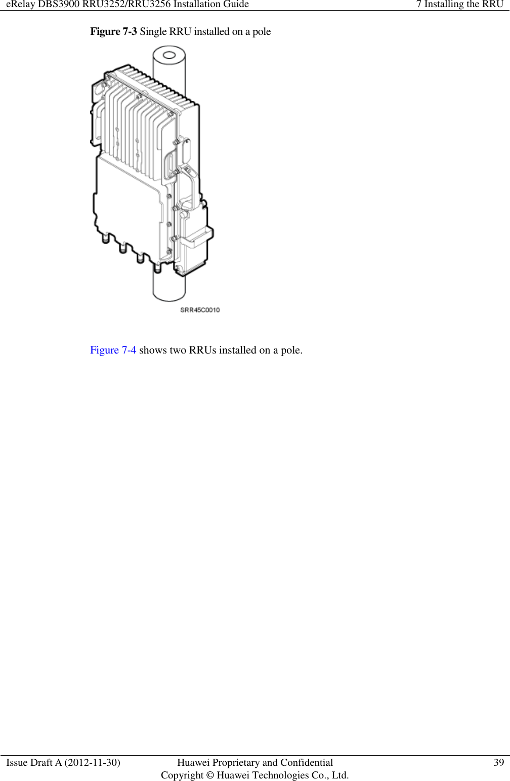
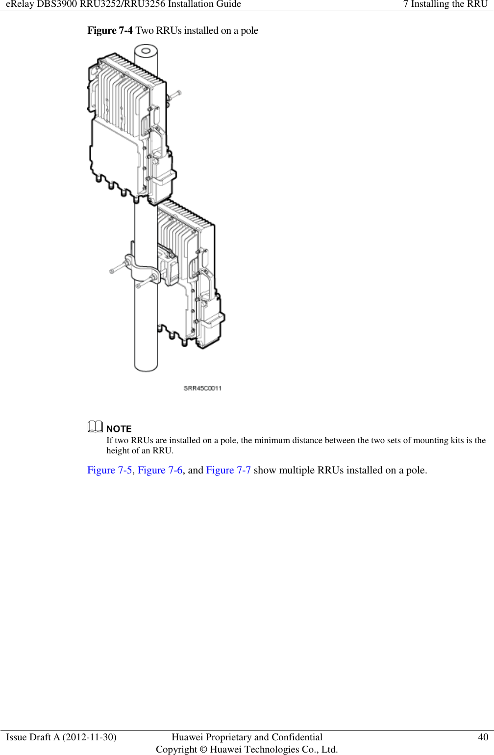
![eRelay DBS3900 RRU3252/RRU3256 Installation Guide 6 Hoisting the RRU and Cables onto a Tower Issue Draft A (2012-11-30) Huawei Proprietary and Confidential Copyright © Huawei Technologies Co., Ltd. 29 Each sling has a load-bearing capacity of more than 200 kg (441 lb), the diameter of the sling must be less than 25 mm (0.98 in.), and the angle at the top of the lifting sling [by the knot] must not be greater than 60 degrees. When hoisting the RRU and mounting kits onto the tower, protect them from colliding with the tower. Hoist the RRU onto the tower before it is installed on a pole, angle steel, or U-steel. Do not hoist the RRU by the handle or lifting eye only, as shown in Figure 6-4 and Figure 6-5. Figure 6-4 Incorrect binding method - hoisting the RRU by the handle only](https://usermanual.wiki/Huawei-Technologies/RRU3276.Installation-Guide-2/User-Guide-3292164-Page-37.png)
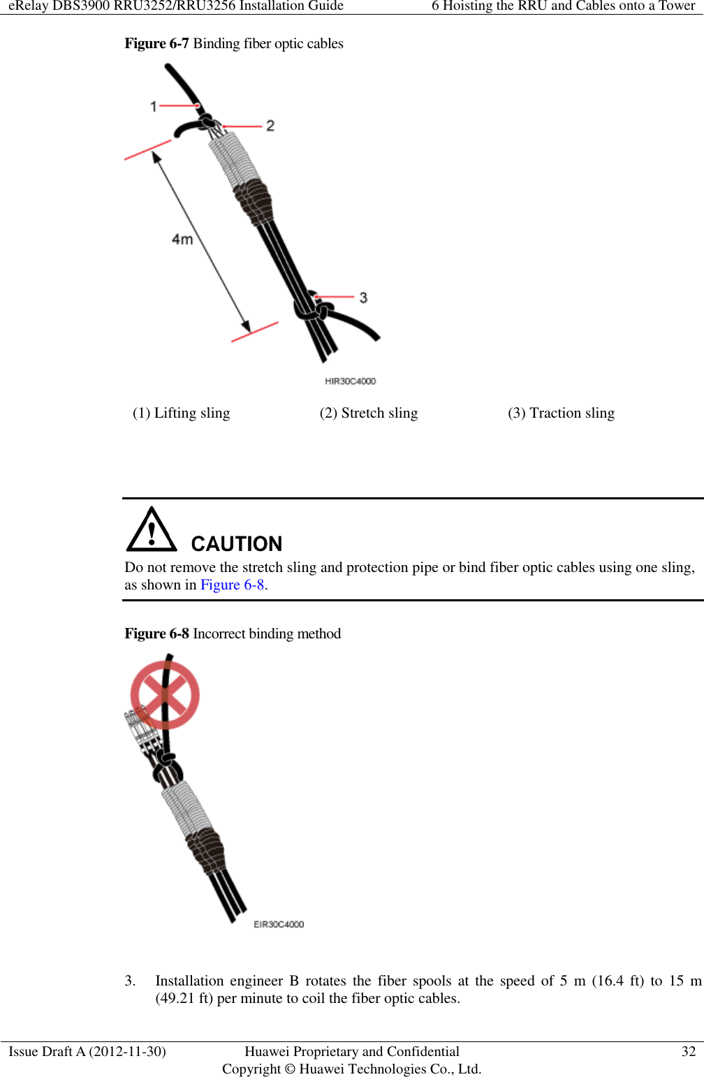
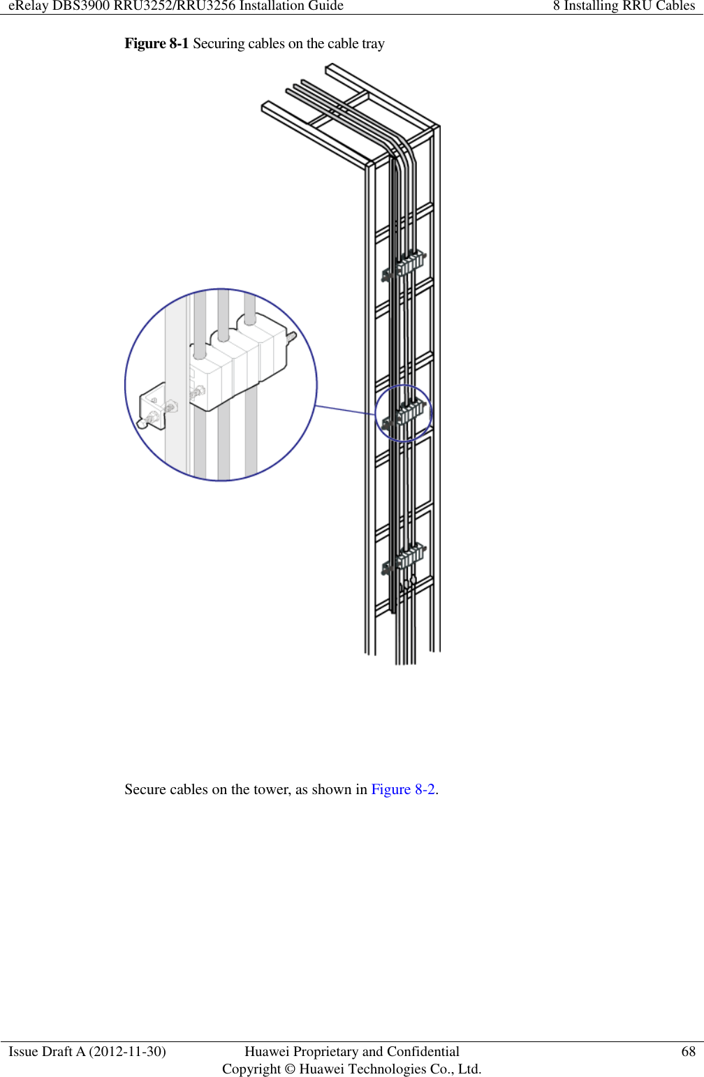
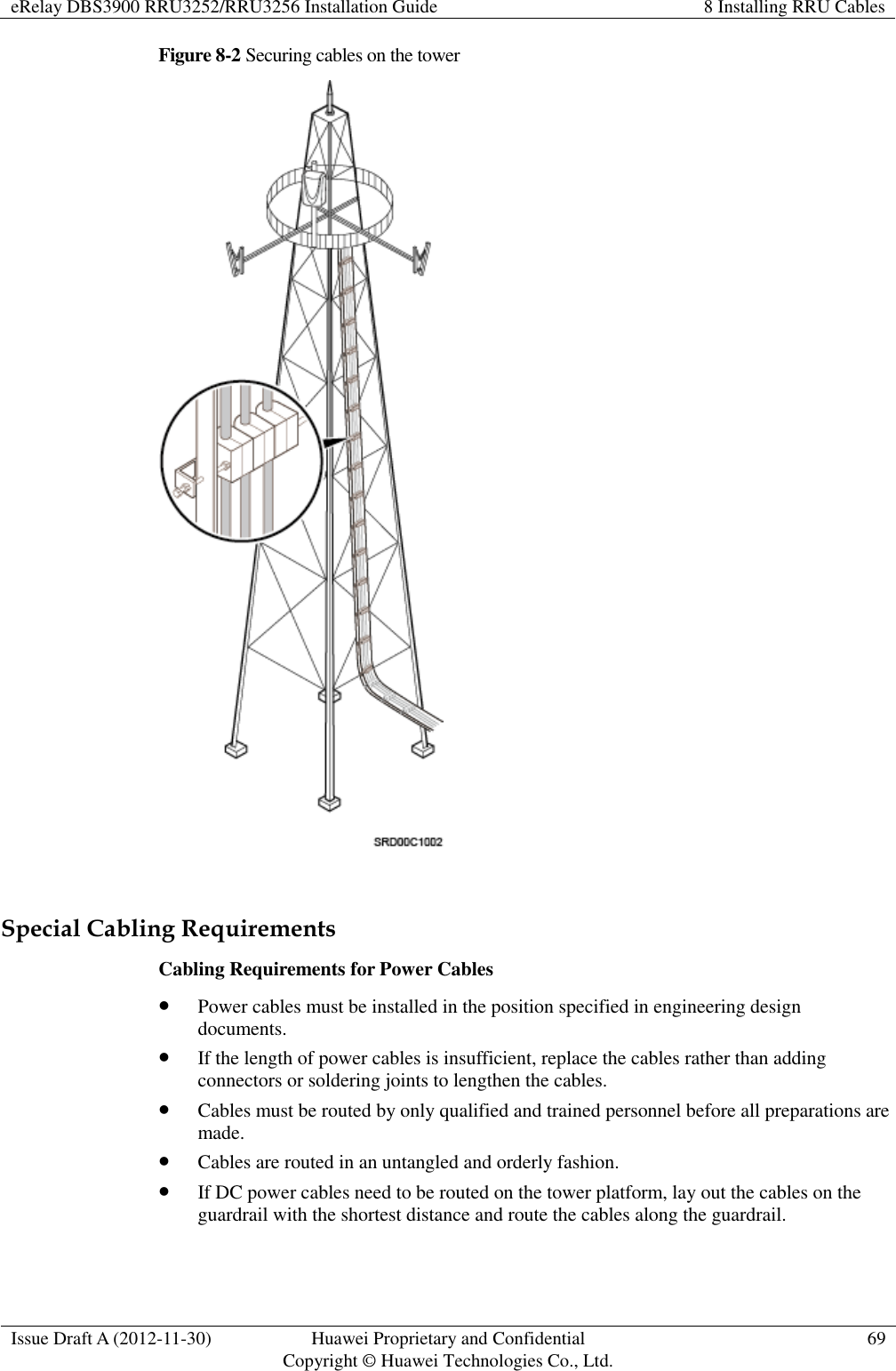
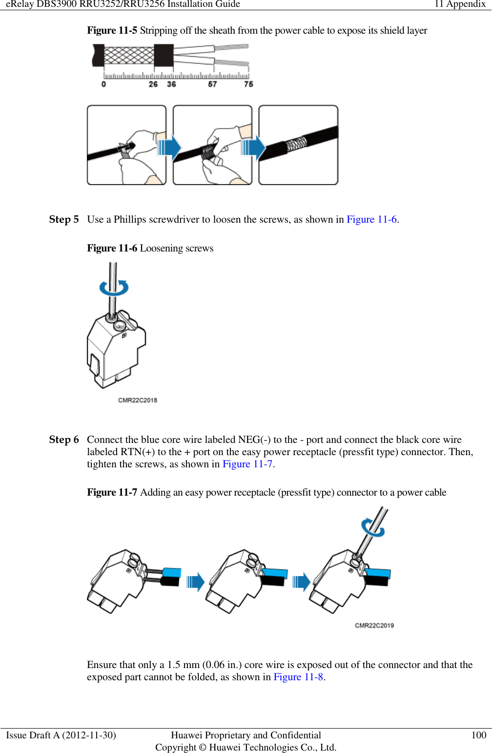
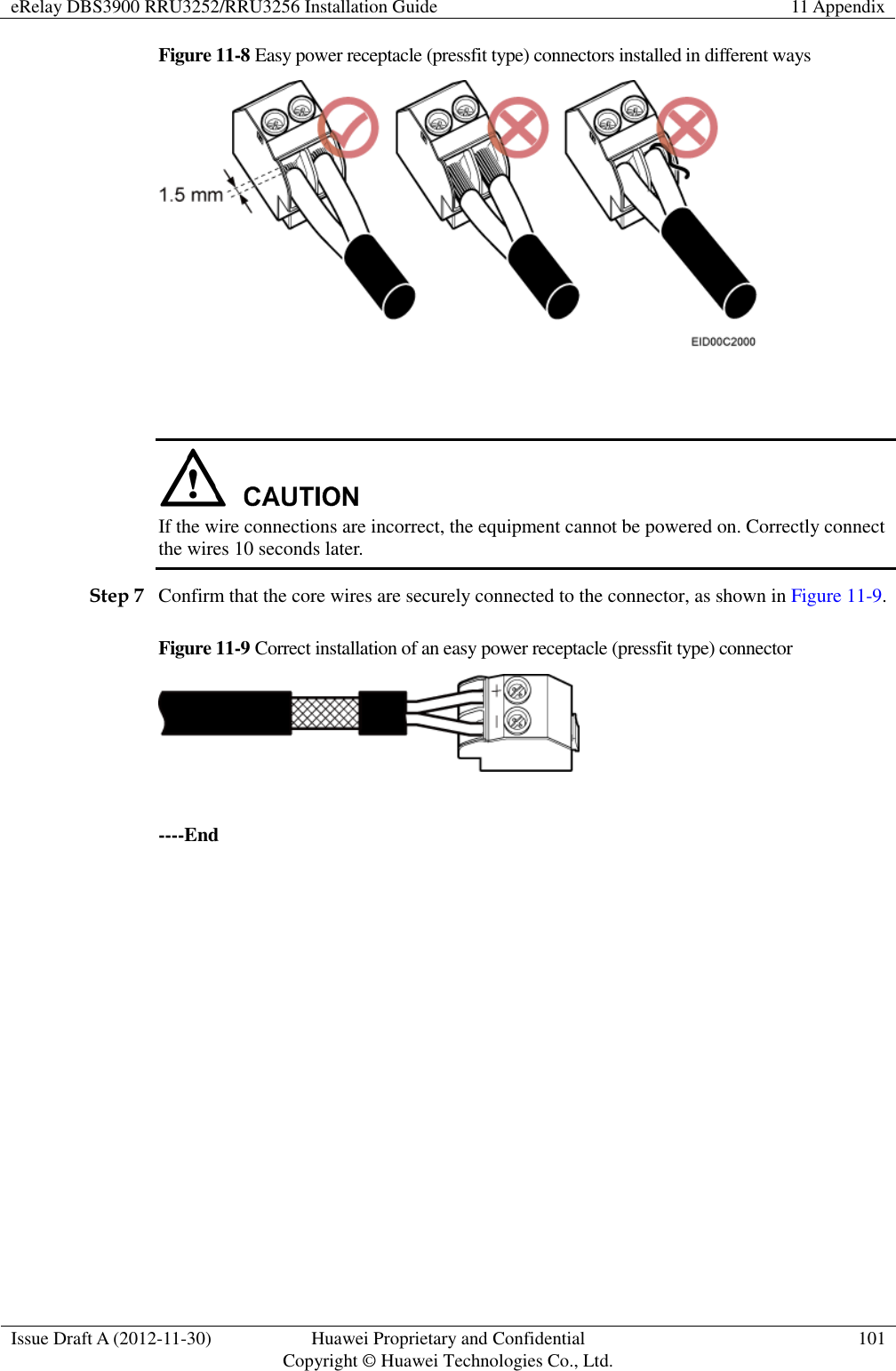
![eRelay DBS3900 RRU3252/RRU3256 Installation Guide 8 Installing RRU Cables Issue Draft A (2012-11-30) Huawei Proprietary and Confidential Copyright © Huawei Technologies Co., Ltd. 67 Cables must be routed away from heat sources, or heat-insulation materials are added between cables and heat sources. Sufficient slack (recommended for about 0.1 m [0.33 ft.]) is provided in cables at turns or the position close to a device, facilitating cable and device maintenance. Indoor Cabling Requirements Cables are routed indoors through the feeder window. Drip loops must be made outside the feeder window, and the requirements for the minimum bending radius are met. When cables are routed indoors, engineers are required indoors for cooperation. The feeder window must be waterproofed. Outdoor Cabling Requirements Cables routed outdoors must be led through a pipe when they may be damaged. AC power cables, transmission cables, and cables buried in the ground must be protected. If cables at the cabinet bottom need to be routed through a pipe along the ground, lead the pipe into the cabinet base for about 3 m (9.84 ft.) to 5 m (16.4 ft.), not into the cabinet. Block the pipe with waterproof tape or silicon gel, and secure the pipe to the cable hole at the cabinet bottom with metal piece. If cables at the cabinet bottom need to be routed through a pipe along the metal cable trough, do not lead the pipe into the cabinet base. The cable trough must be sealed and routed through the cable hole at the cabinet bottom. Cables are secured with cable clips. Cables are routed neatly along the specified cabling direction and secured with cable clips. The positions for cable clips are determined onsite. For example, the cable clips for the 7/8" feeder are installed at the spacing of 1.5 m (4.92 ft.) to 2 m (6.56 ft.) in the same direction, and the cable clips for the power cables are installed at the spacing of 1 m (3.28 ft.) to 1.5 m (4.92 ft.) in the same direction. Cable clips must be vertical with cables, and the cables in a cable clip must be parallel. After routing cables neatly and correctly, tighten the screws on cable clips. Secure cables on the cable tray, as shown in Figure 8-1.](https://usermanual.wiki/Huawei-Technologies/RRU3276.Installation-Guide-2/User-Guide-3292164-Page-75.png)