Huawei Technologies RRU3276 Remote Radio Unit User Manual Installation Guide
Huawei Technologies Co.,Ltd Remote Radio Unit Installation Guide
UserManual.wiki
>
Huawei Technologies
>
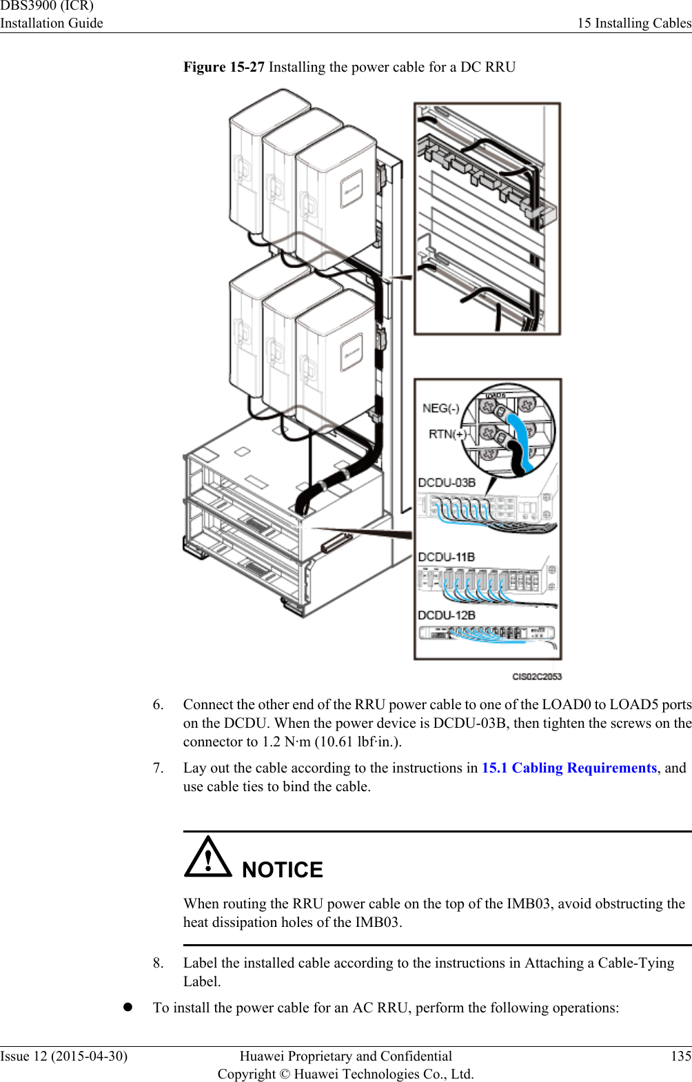
RRU3276 User Manual
>
Installation Guide
Contents
1.
Compliance and Safety Manual
2.
Installation Guide 2
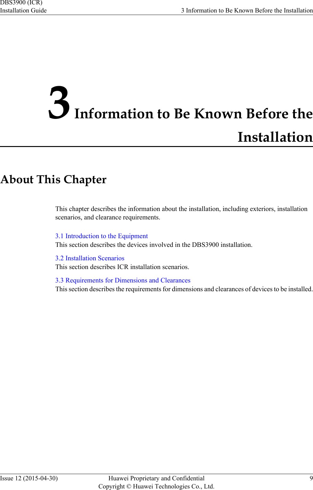
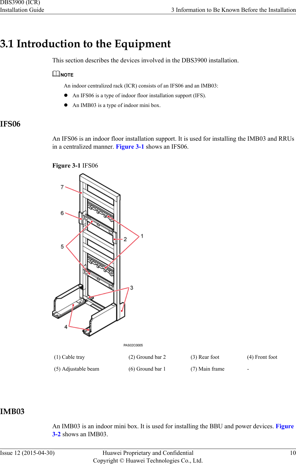
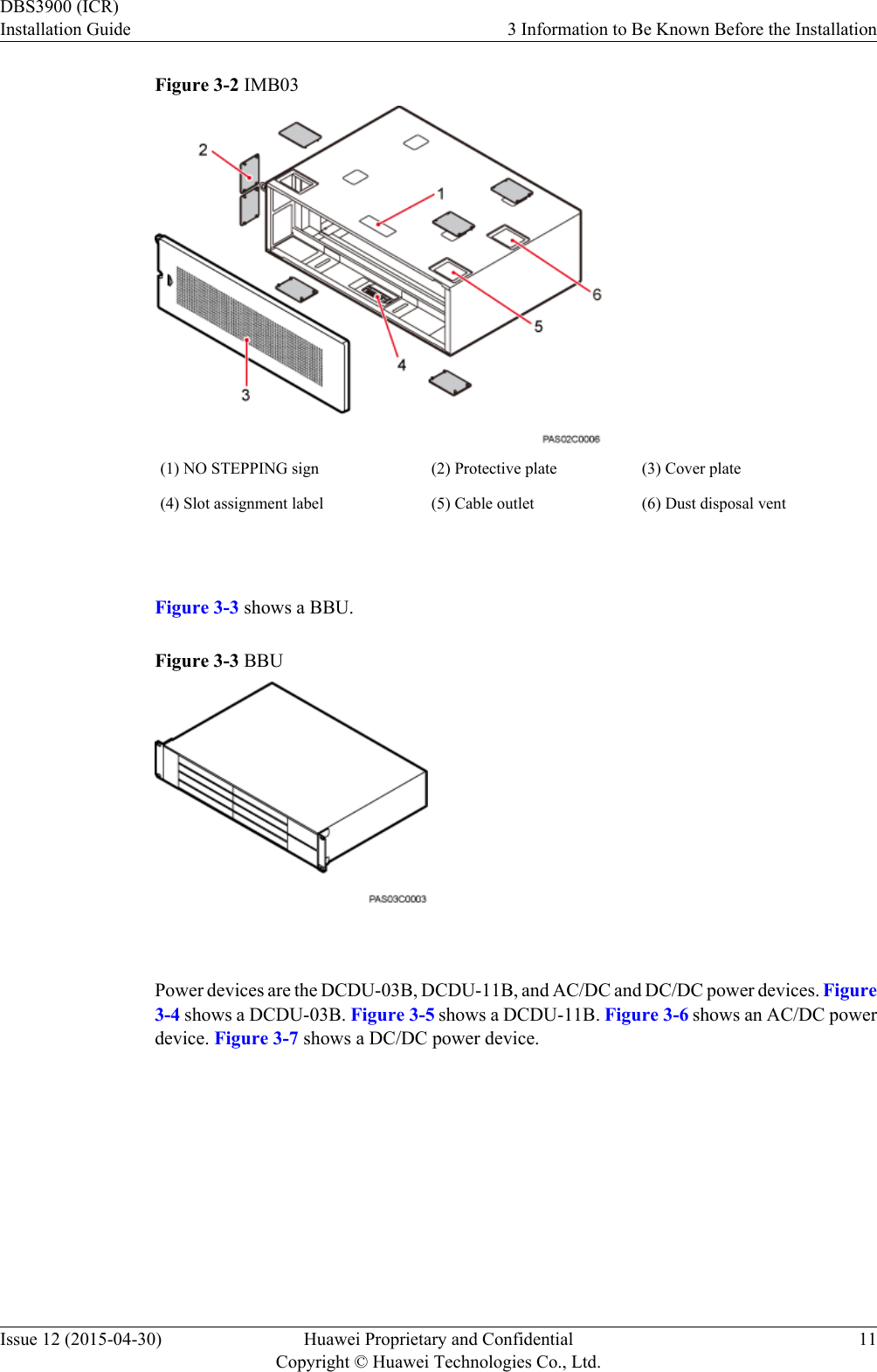
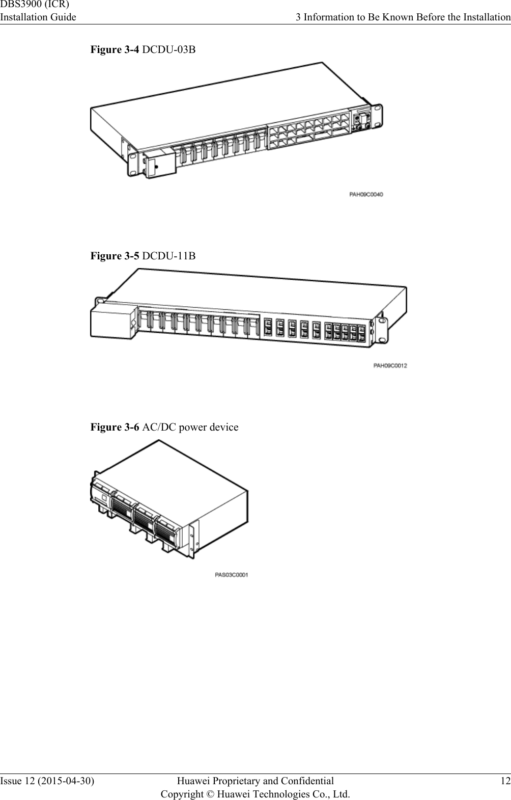
3.
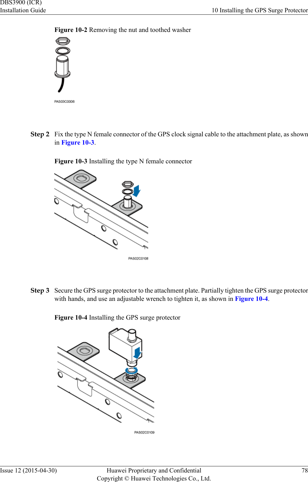
Installation Guide
Installation Guide
Navigation menu
Upload a User Manual
Namespaces
Wiki Guide
HTML
PDF
Info
Views
User Manual
Discussion / Help
Navigation
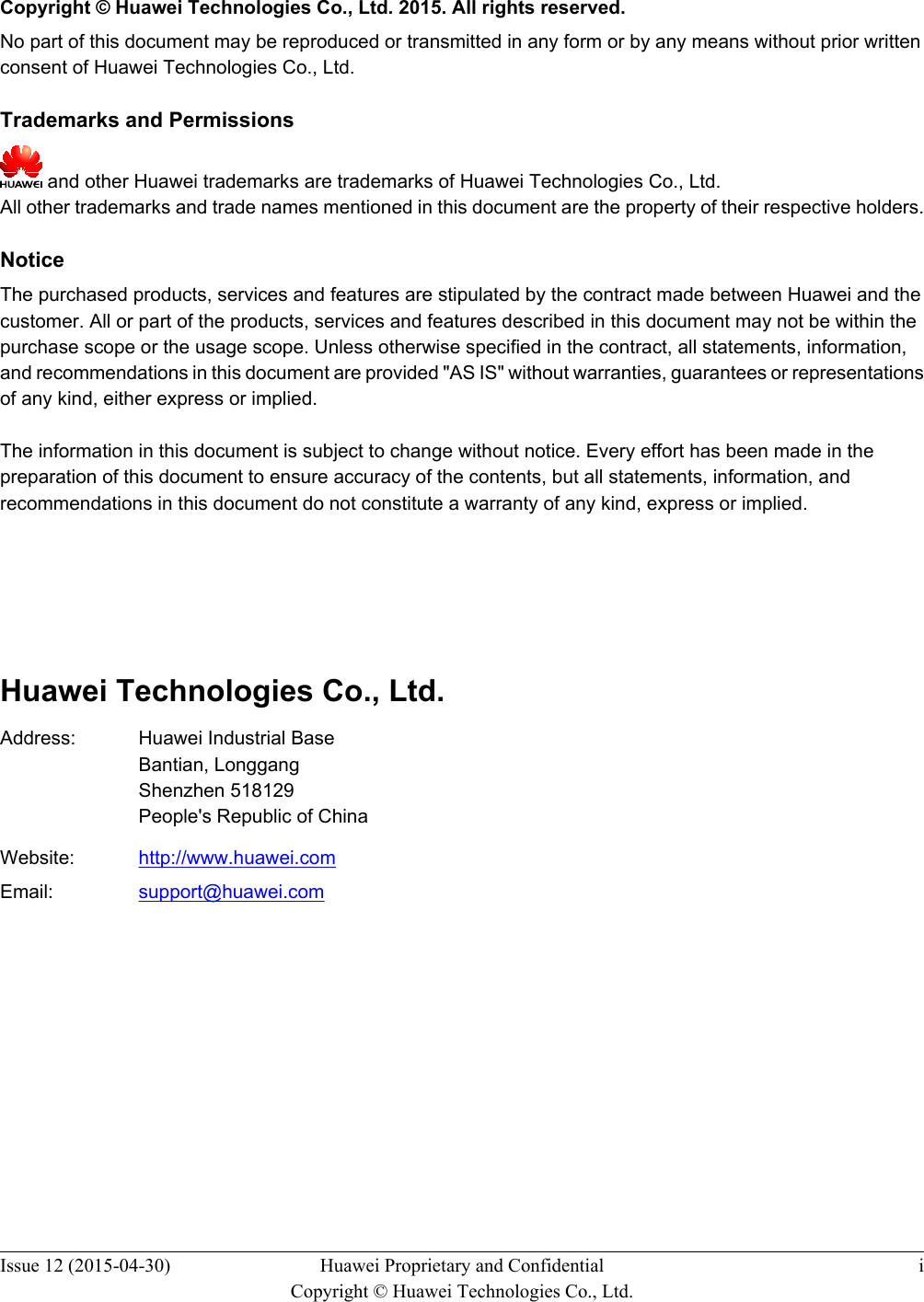
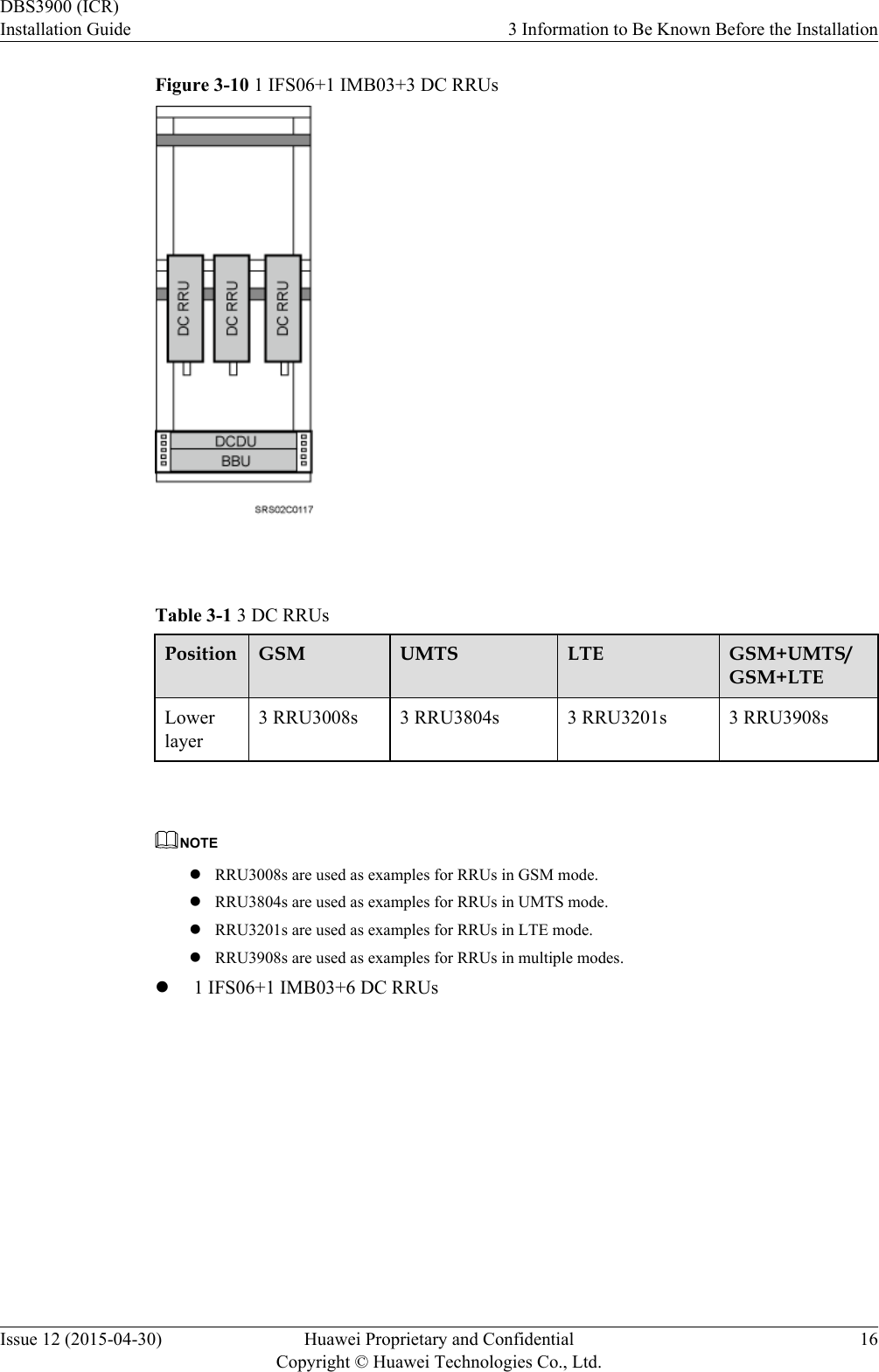
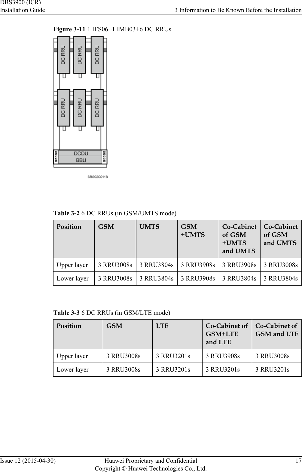

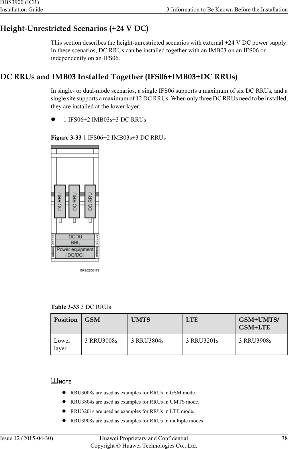
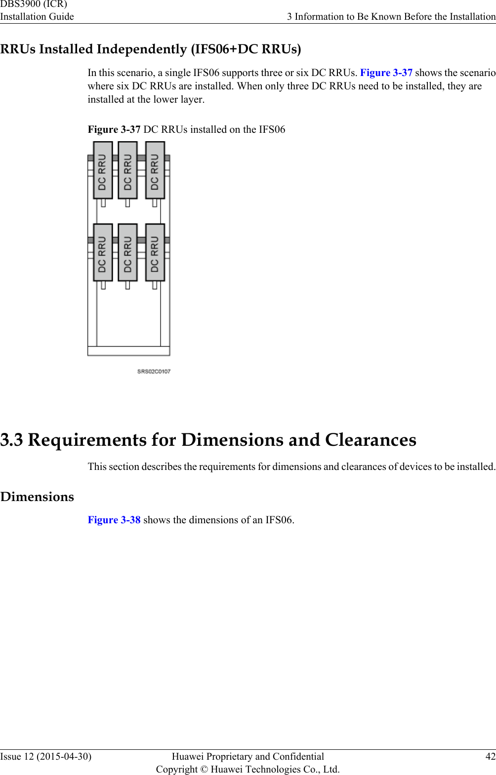
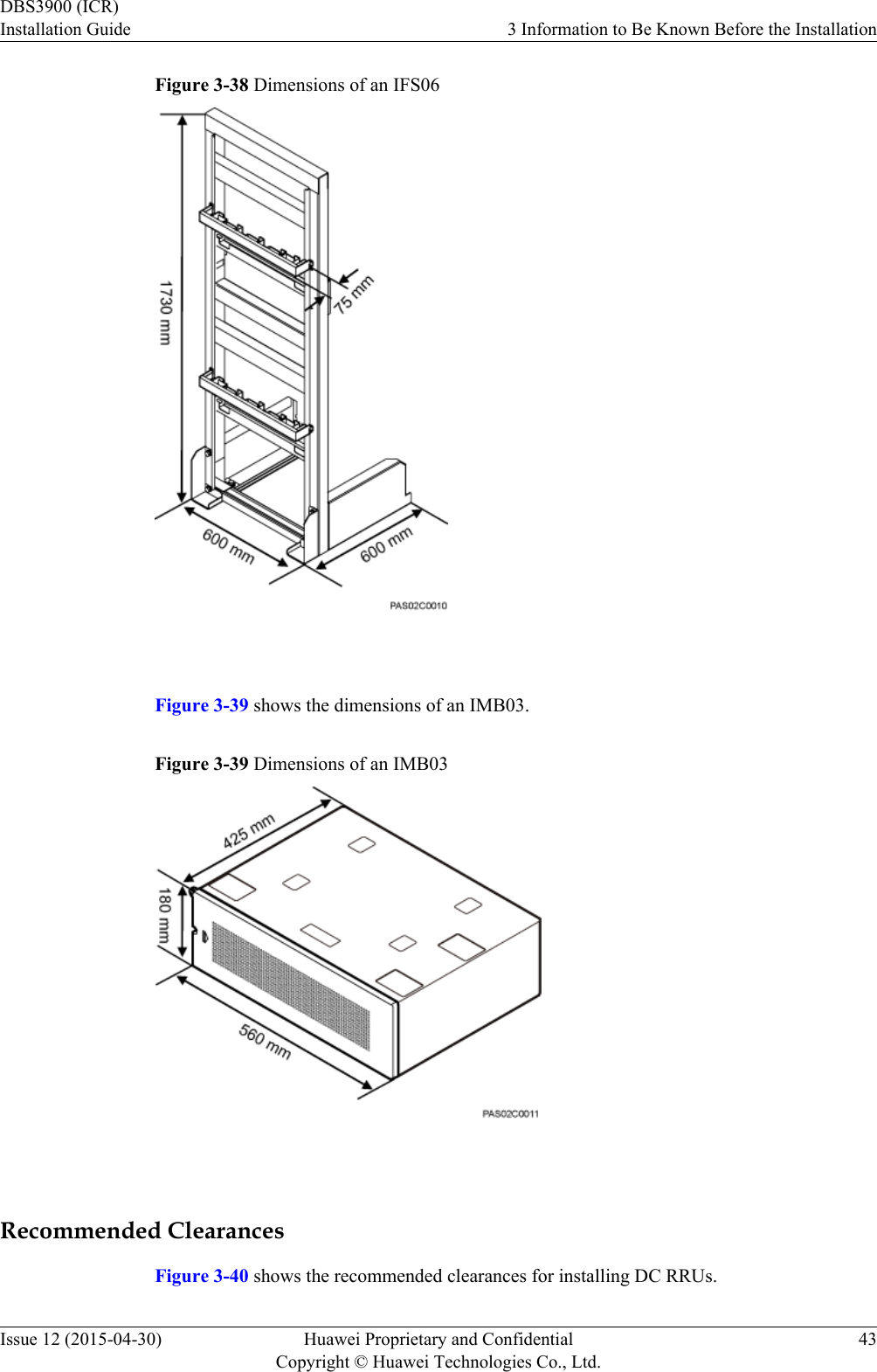
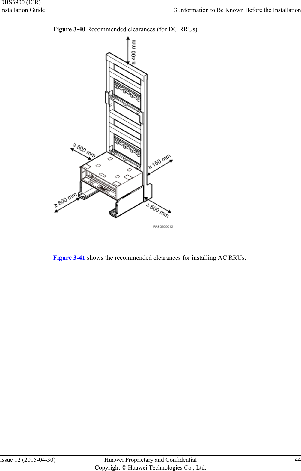
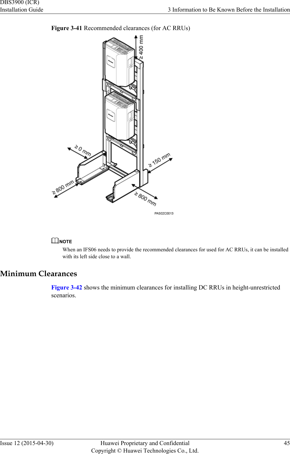
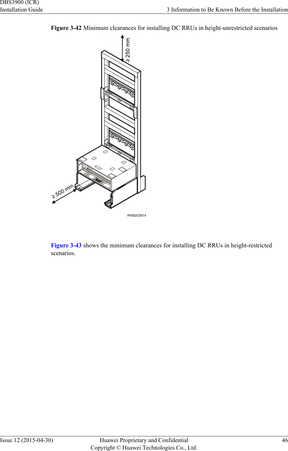
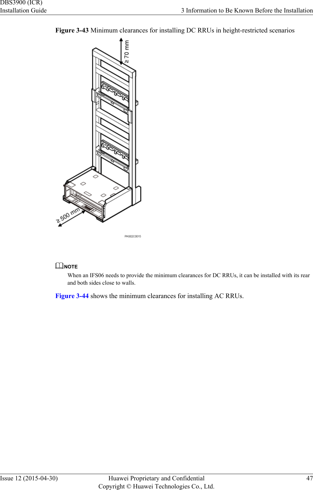
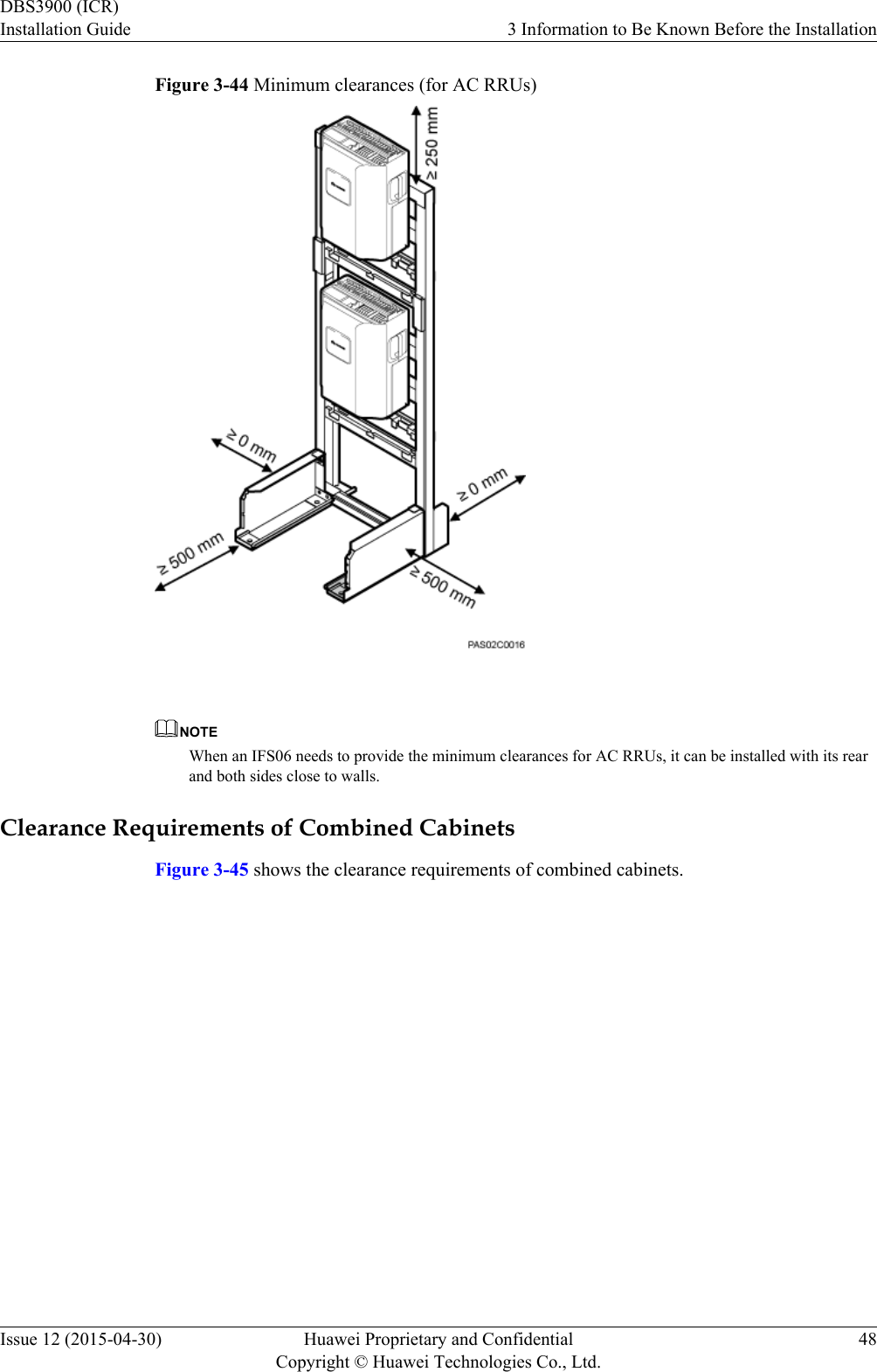
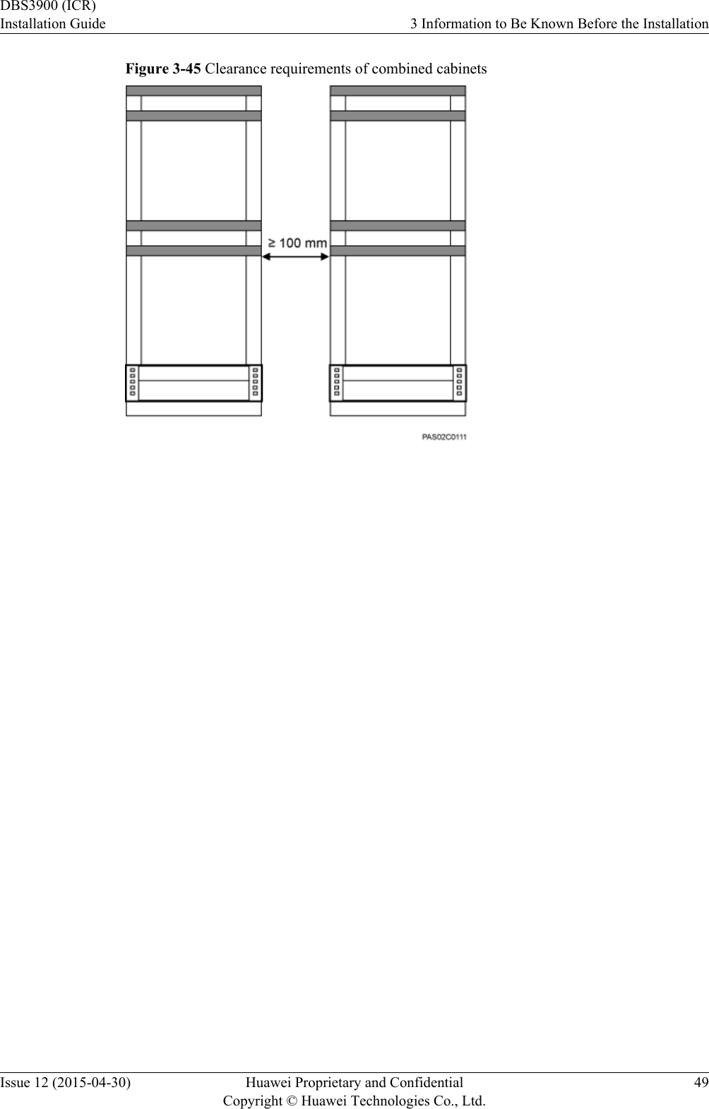
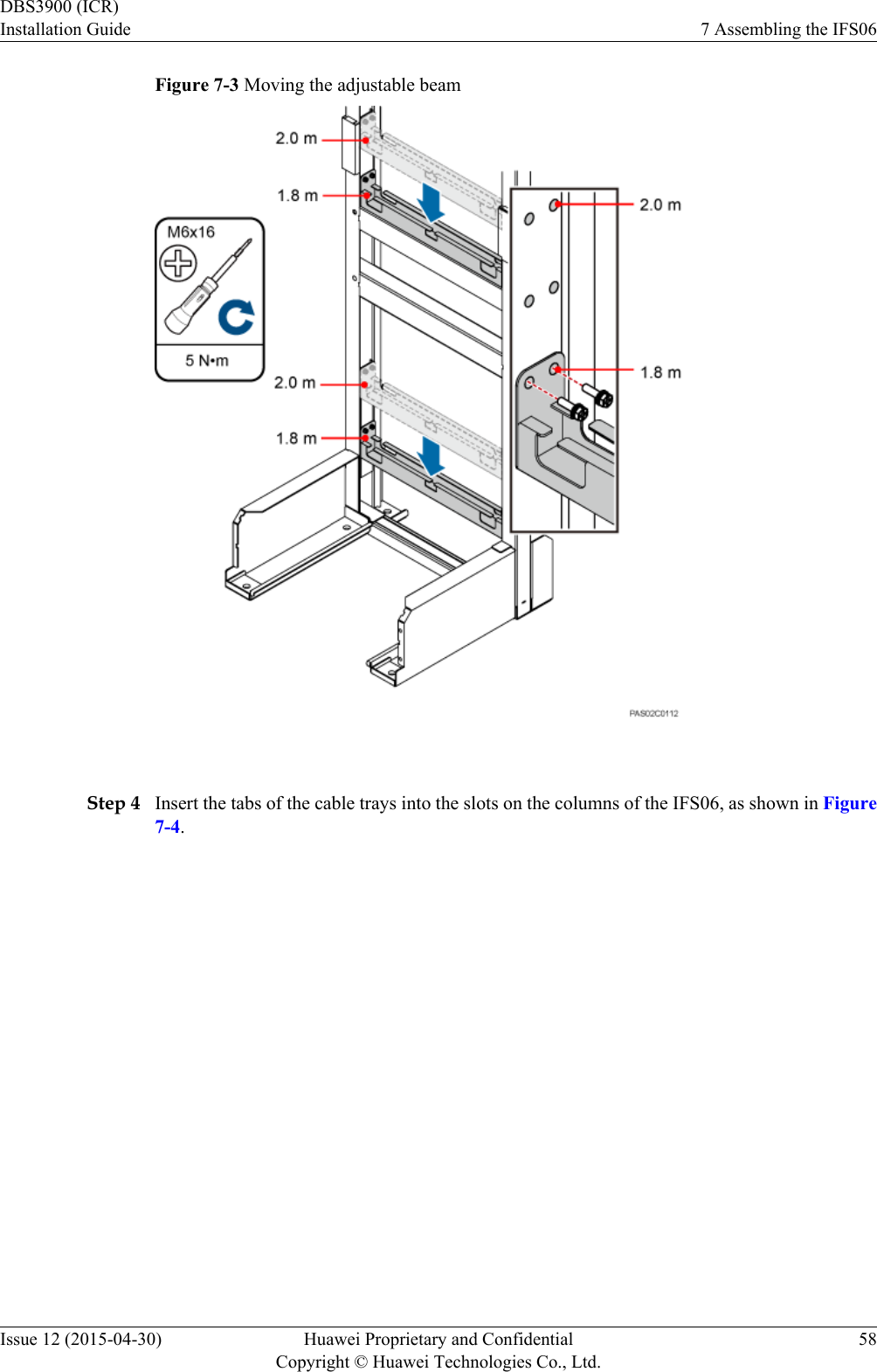
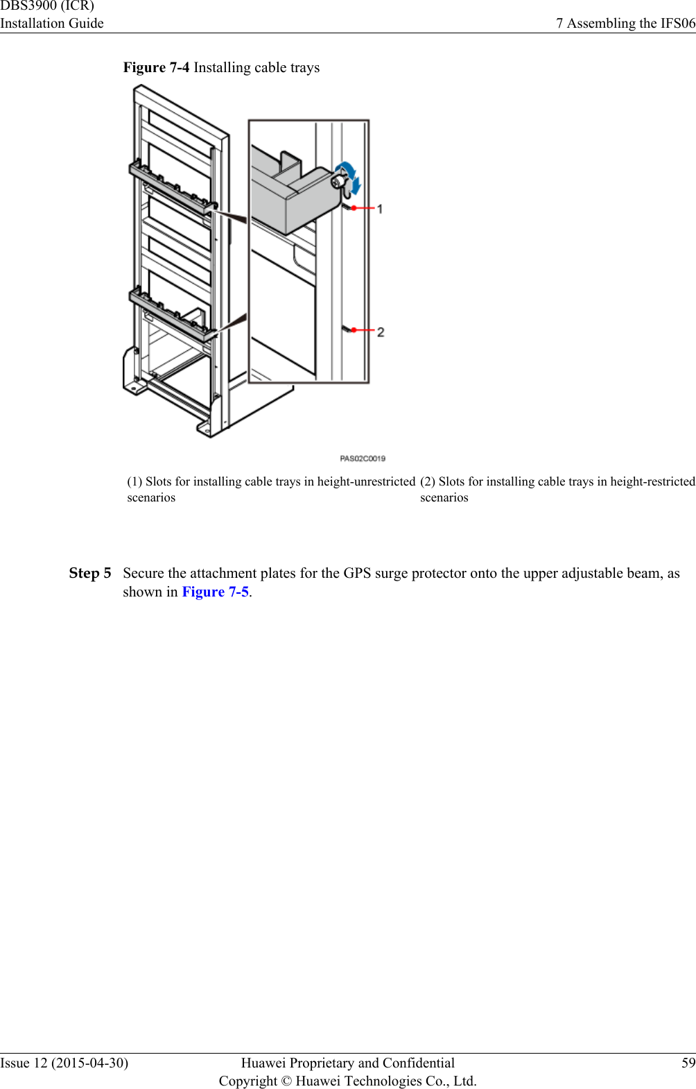
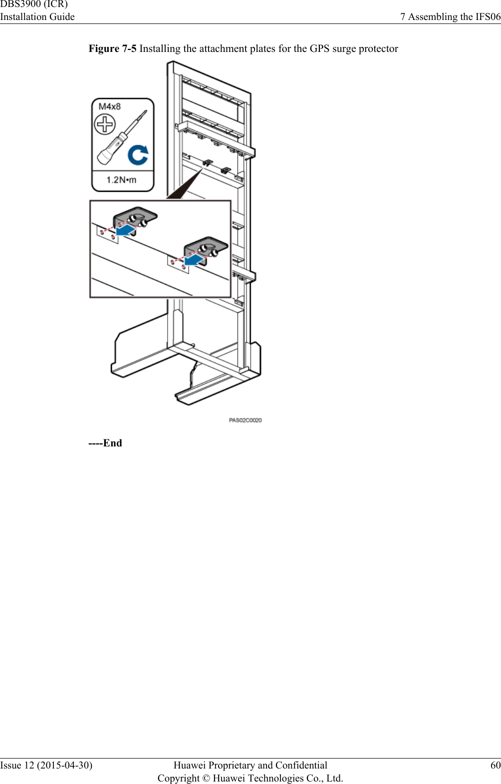
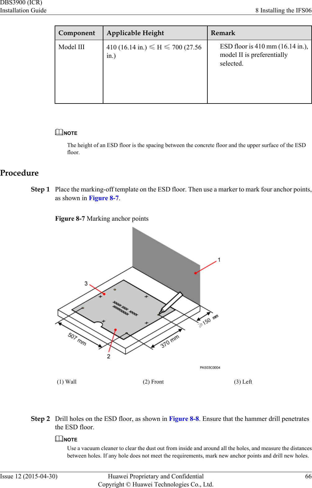
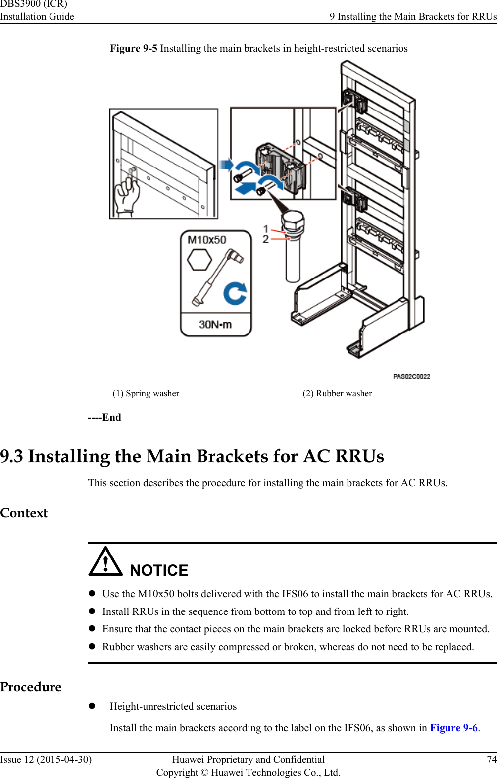
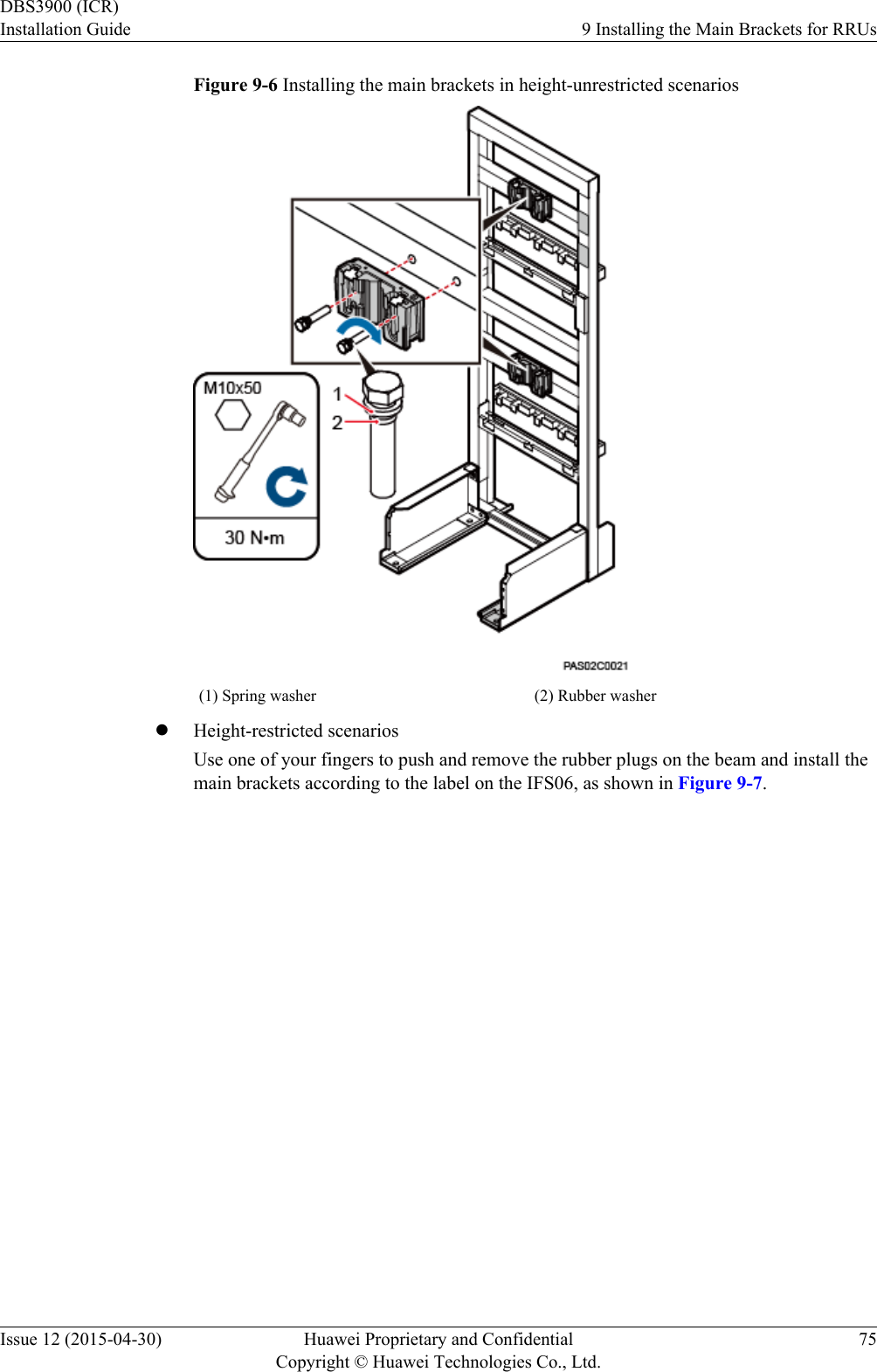
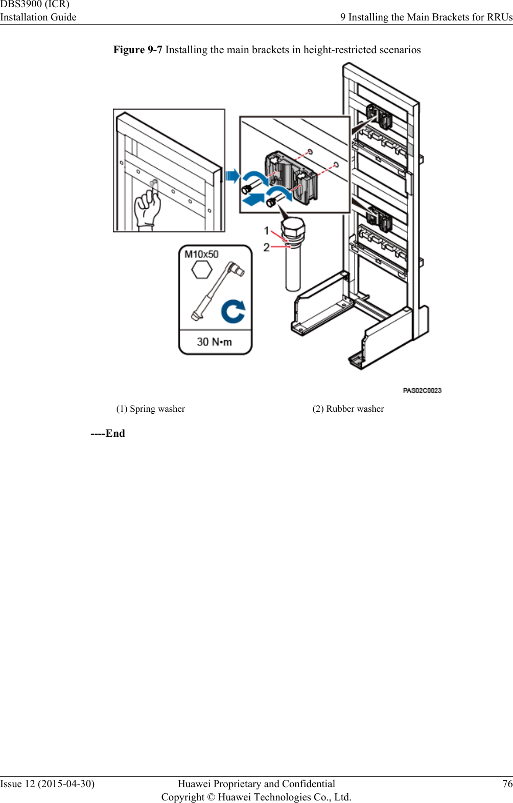
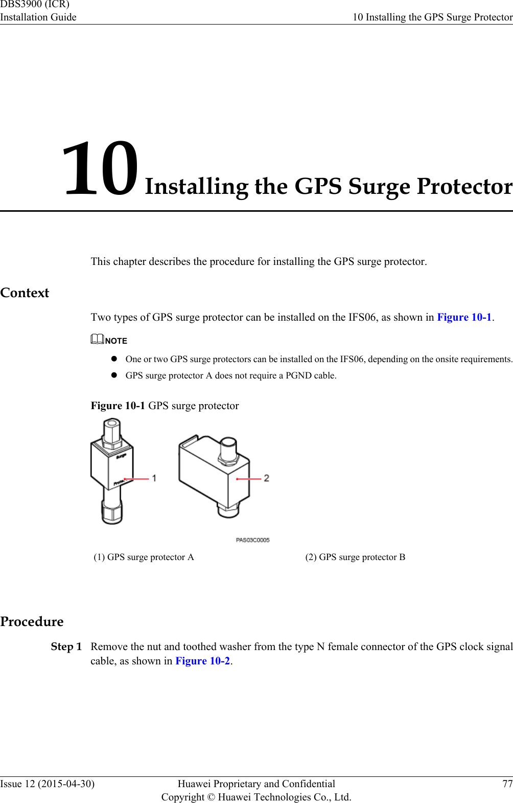
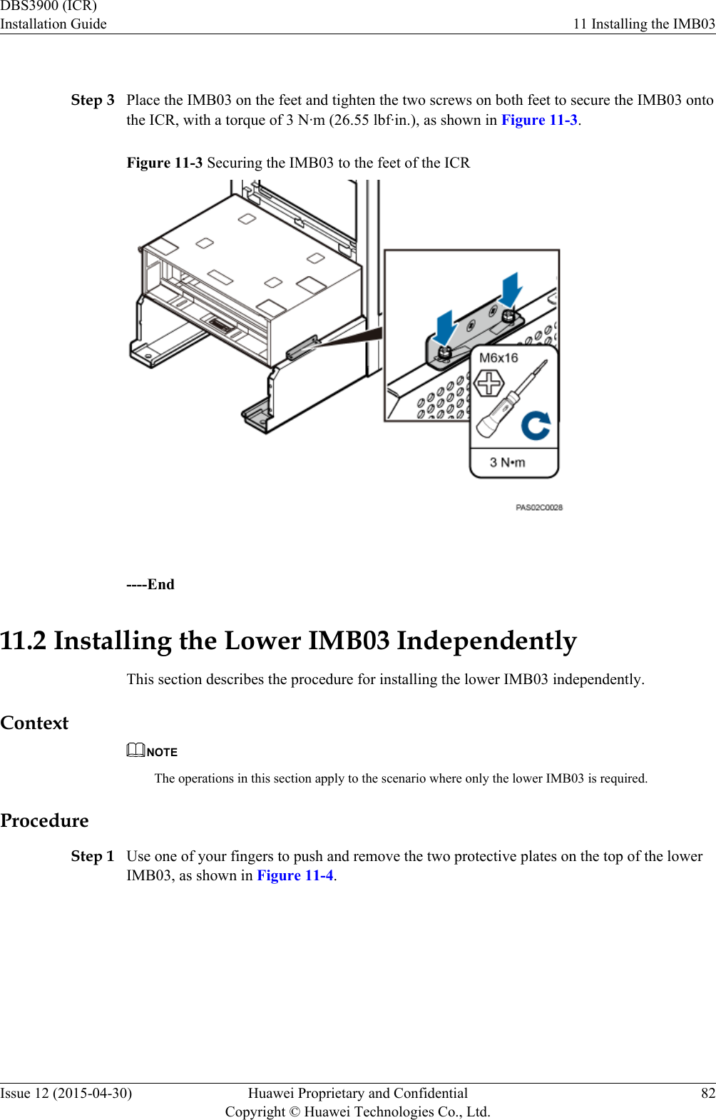
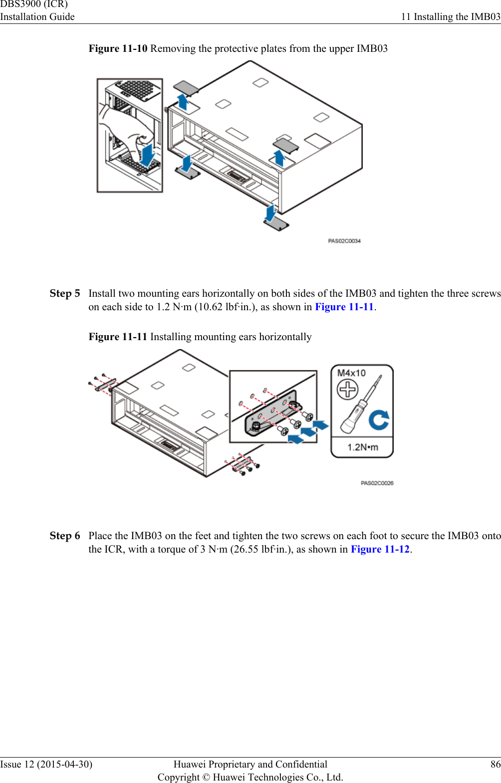
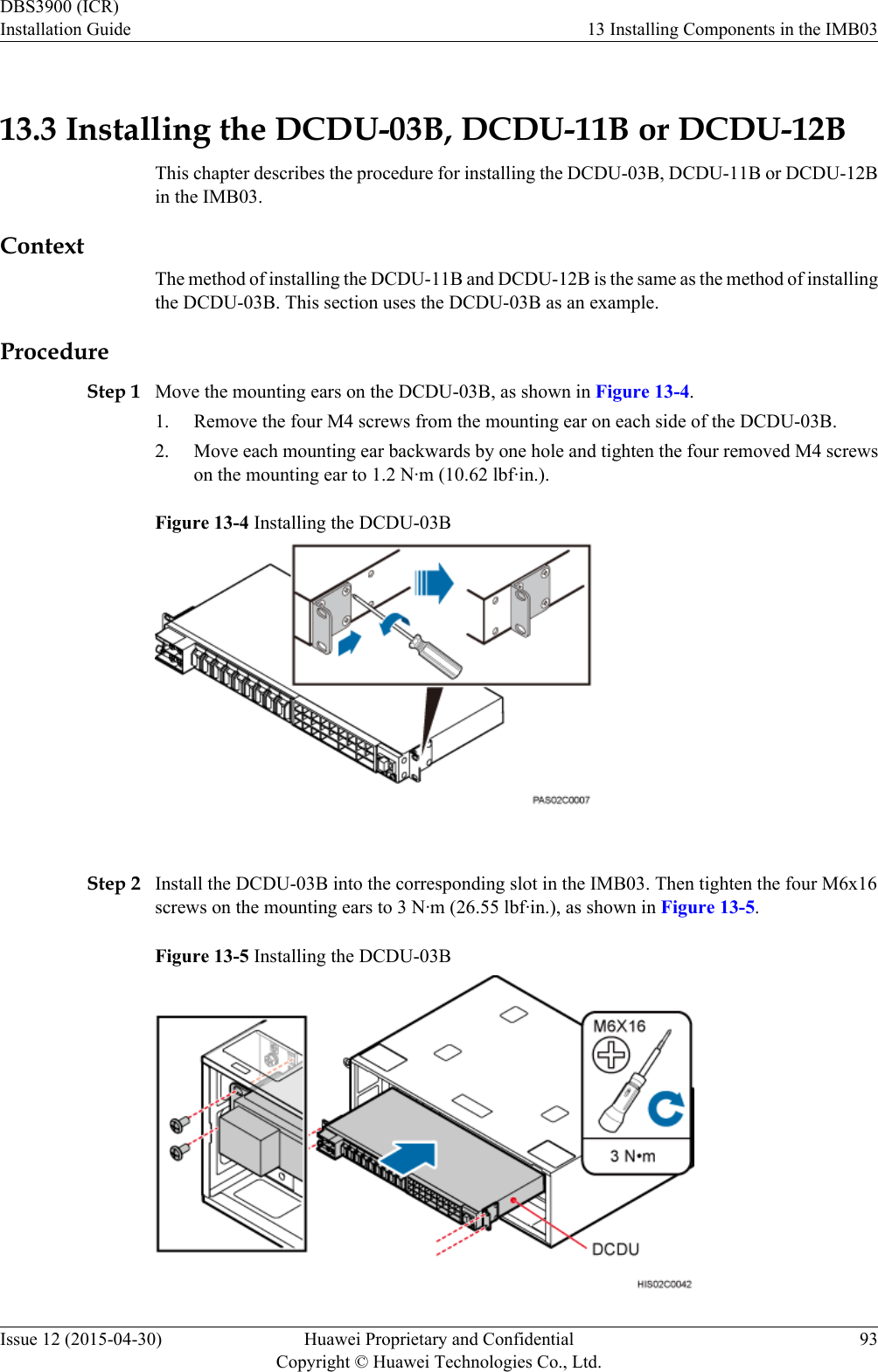
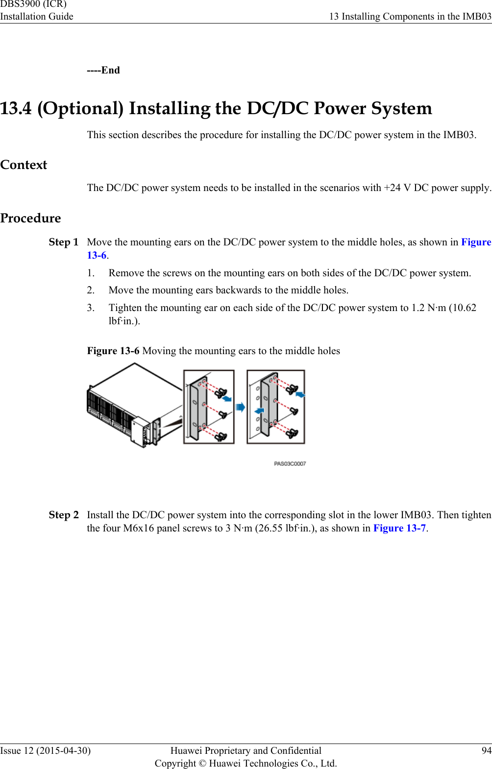
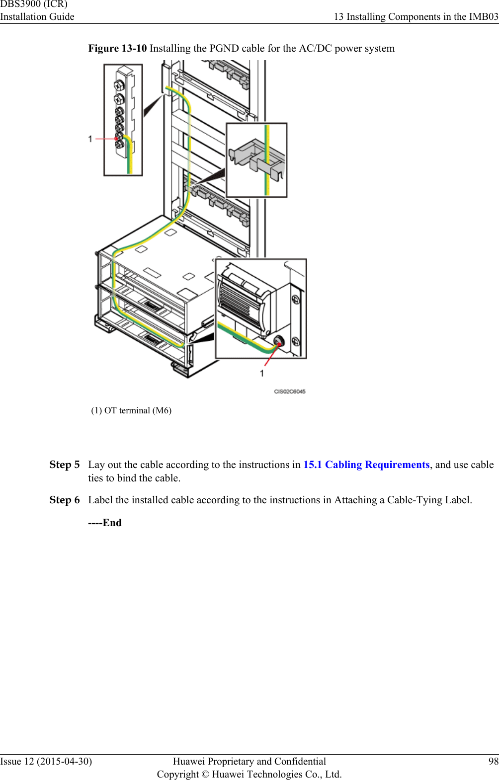
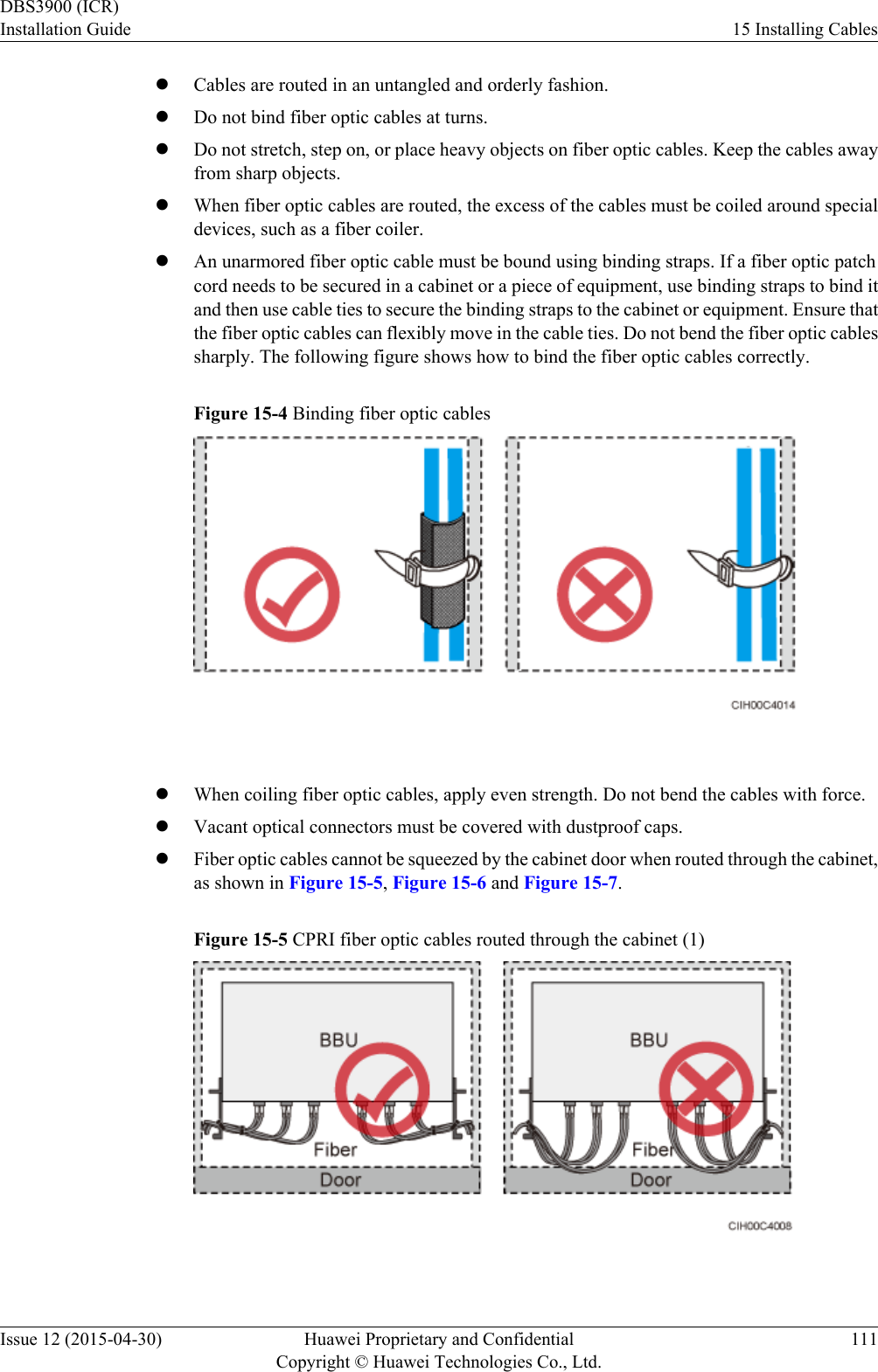
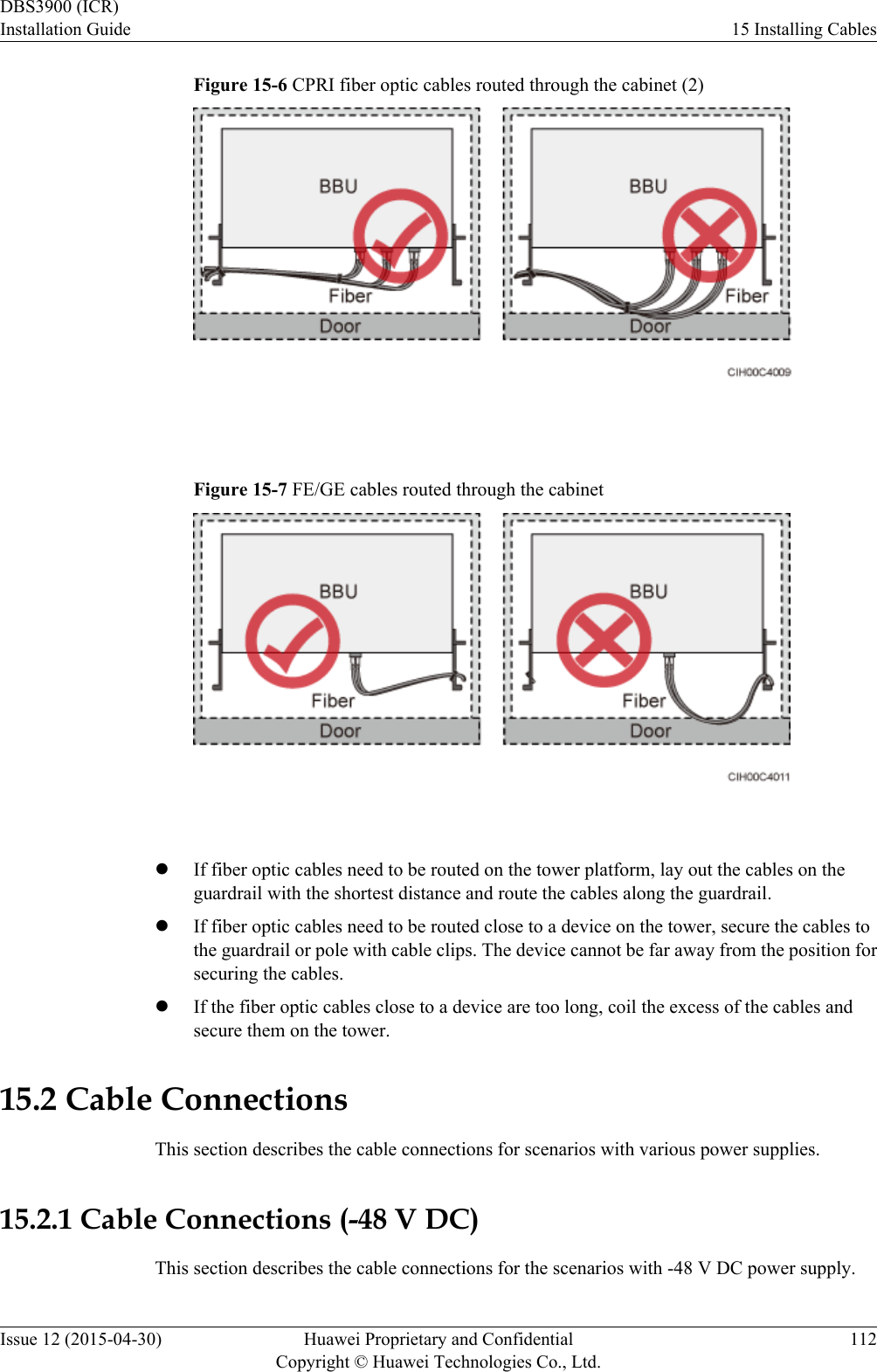
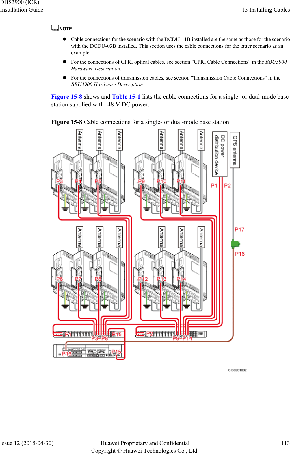
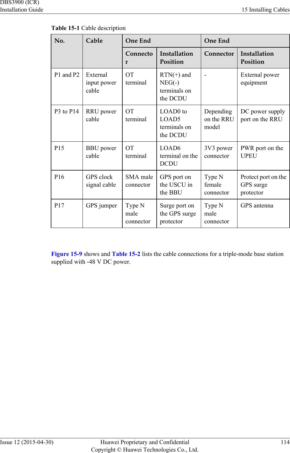
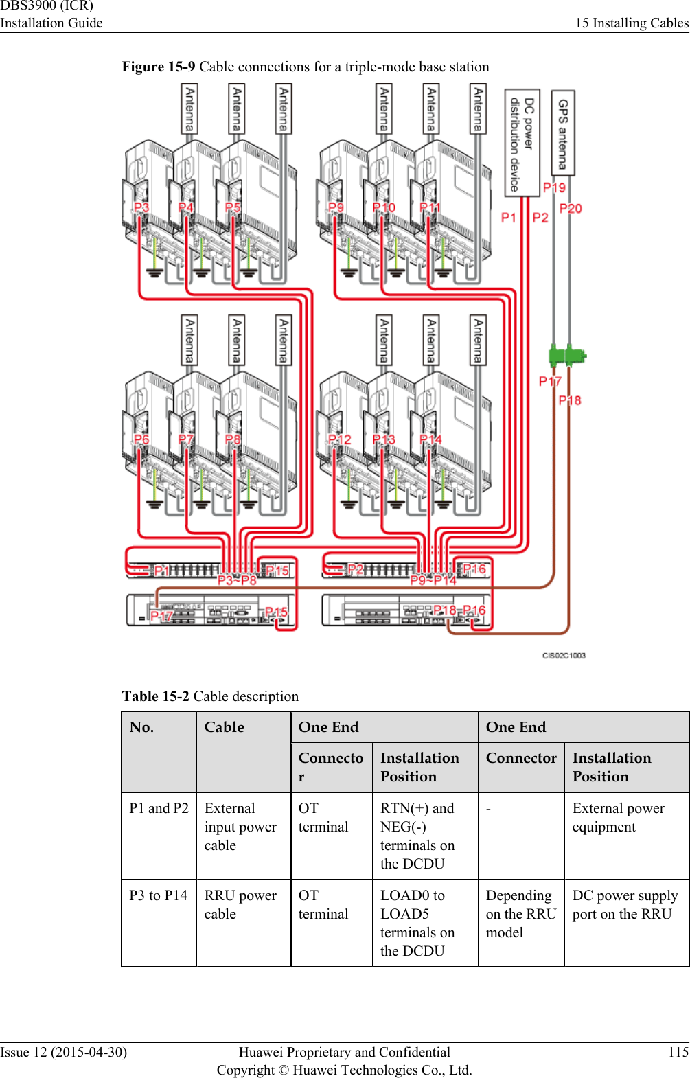
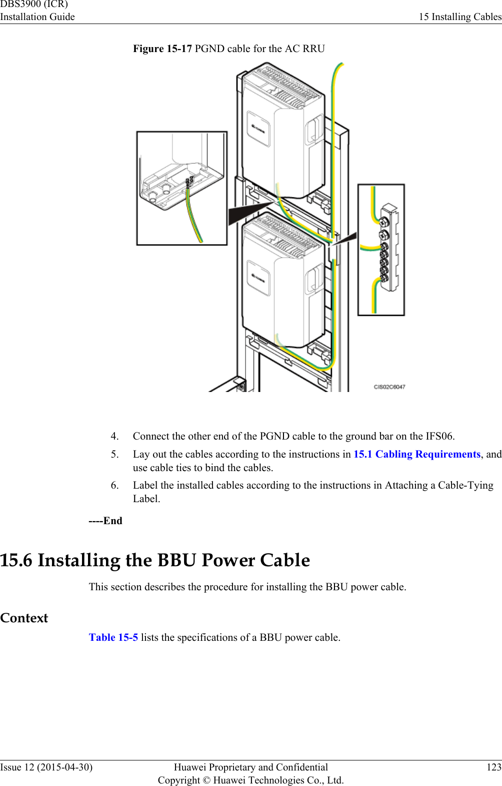
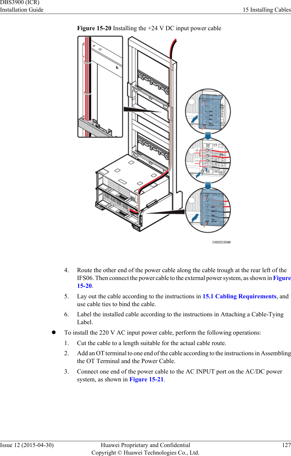
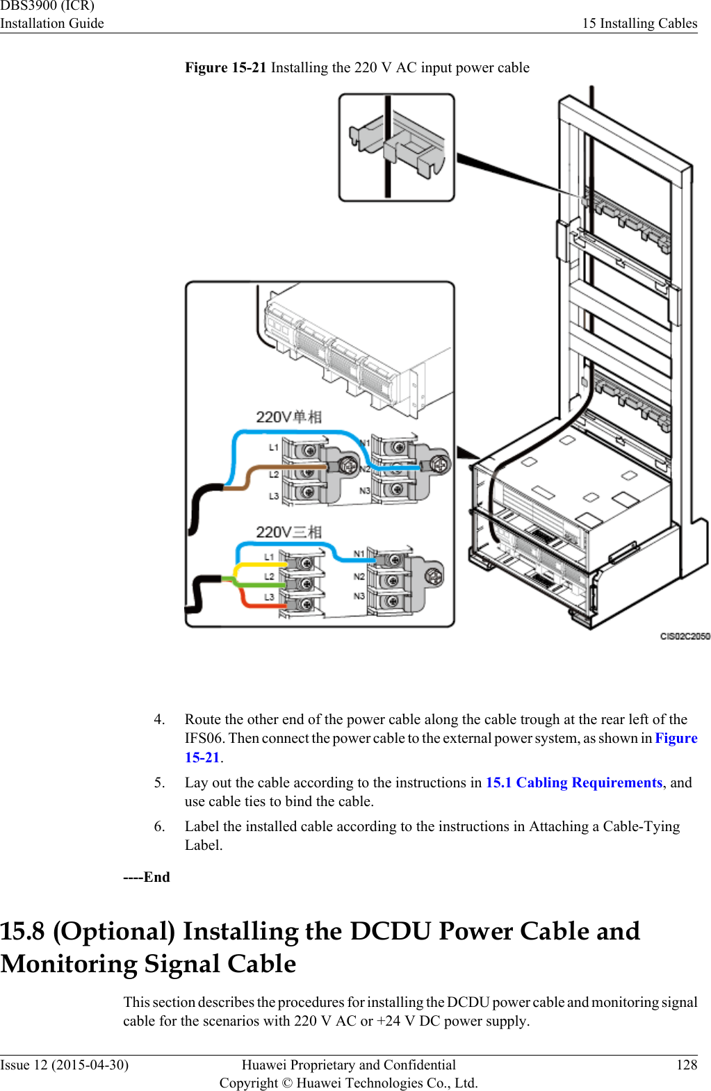
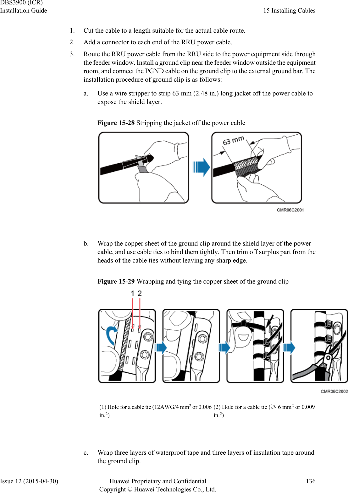
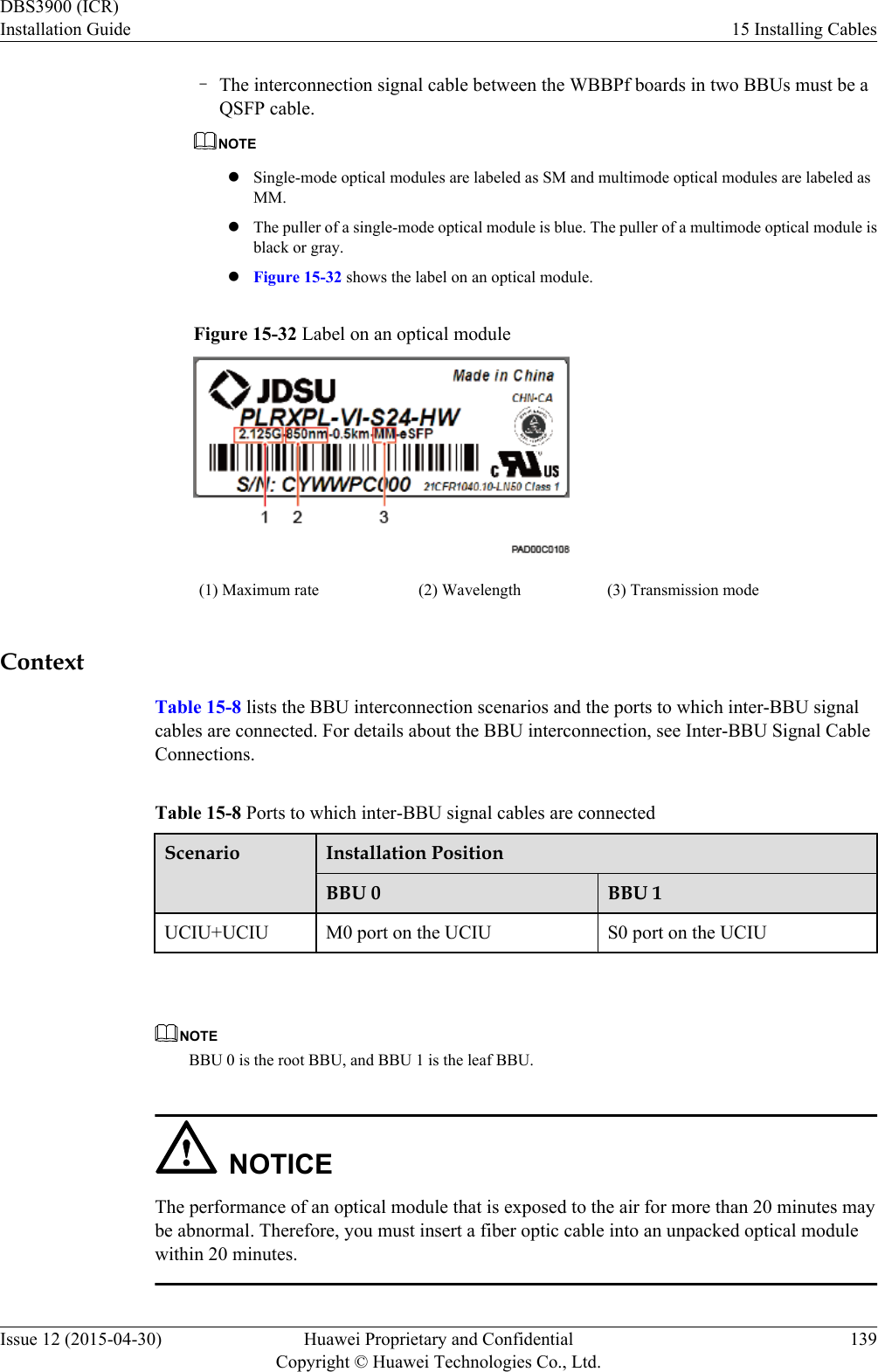
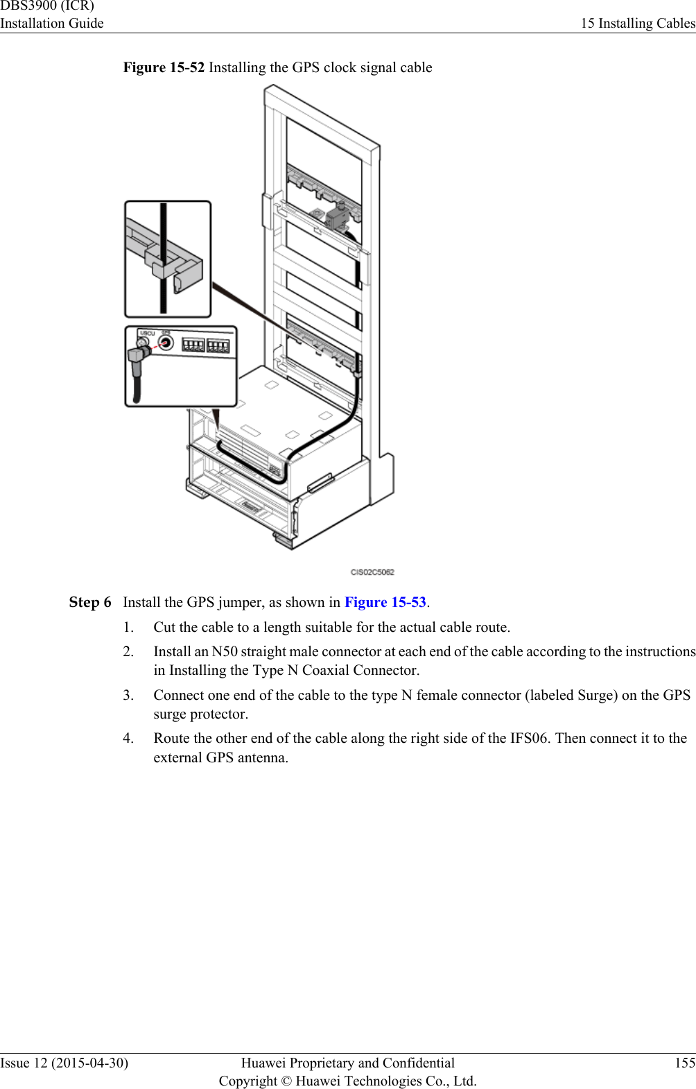
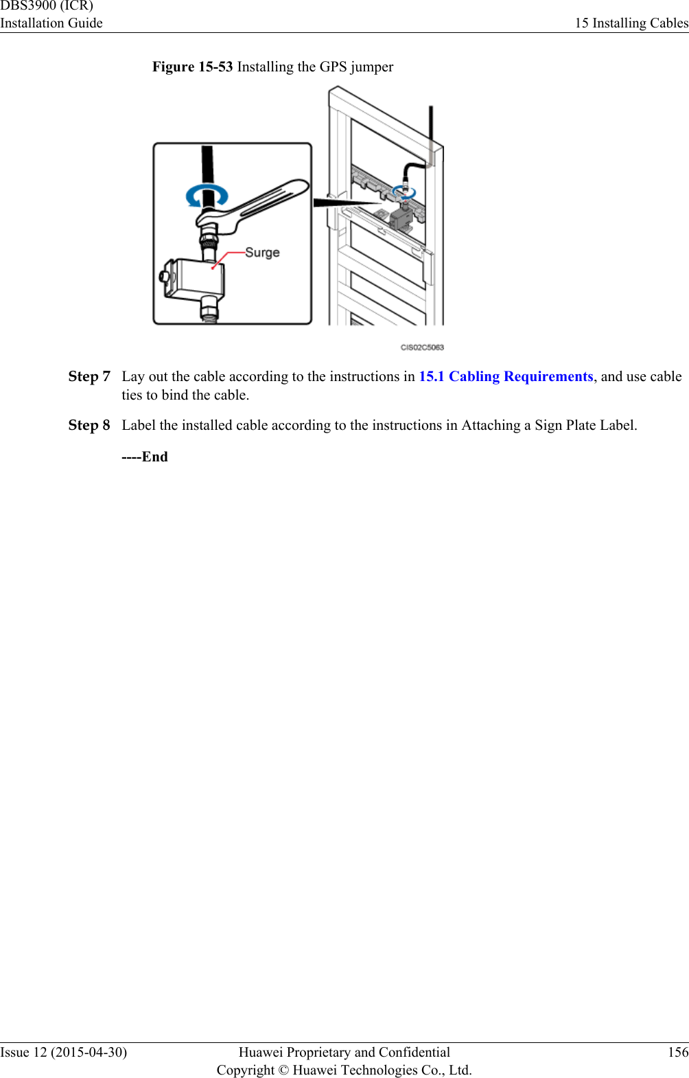
![15.1 Cabling RequirementsCables must be routed according to the specified cabling requirements to prevent signalinterference.NOTEIf a cable listed below is not required, skip the routing requirements of the cable.General Cabling RequirementsRequirements for Bending RadiuslThe bending radius of the 7/8'' feeder must be more than 250 mm (9.84 in.), and the bendingradius of the 5/4'' feeder must be more than 380 mm (14.96 in.).lThe bending radius of the 1/4'' jumper must be more than 35 mm (1.38 in.). The bendingradius of the super-flexible 1/2'' jumper must be more than 50 mm (1.97 in.), and the bendingradius of the ordinary 1/2'' jumper must be more than 127 mm (5 in.).lThe bending radius of the power cable or PGND cable must be at least three times thediameter of the cable.lThe bending radius of a fiber optic cable is at least 20 times the diameter of the fiber opticcable, and the minimum bending radius of the breakout cable at each end of the fiber opticcable is 30 mm (1.18 in.).lThe bending radius of the E1/T1 cable must be at least three times the diameter of the cable.lThe bending radius of the signal cable must be at least five times the diameter of the cable.Requirements for Cable BindinglThe same types of cable must be bound together.lDifferent types of cable must be separately routed with the minimum spacing of 30 mm(1.18 in.) and cannot be entangled.lThe cables must be bound tightly and neatly. The sheaths of the cables must not be damaged.lCable ties are installed in the same direction, and those at the same horizontal line must bein a straight line.lThe excess of indoor cable ties is trimmed off, and the excess of outdoor cable ties allowsabout 5 mm (0.2 in.), without remaining rough edges.lLabels or nameplates must be attached to both ends, joints, or turns of cables after they areinstalled.Security RequirementslCables should be placed away from sharp objects or wall burrs. If these positions areinevitable, protect the cables with protection pipes.lCables must be routed away from heat sources, or heat-insulation materials are addedbetween cables and heat sources.lSufficient slack (recommended for about 0.1 m [0.33 ft]) is provided in cables at turns orthe position close to a device, facilitating cable and device maintenance.Indoor Cabling RequirementslCables are routed indoors through the feeder window.DBS3900 (ICR)Installation Guide 15 Installing CablesIssue 12 (2015-04-30) Huawei Proprietary and ConfidentialCopyright © Huawei Technologies Co., Ltd.106](https://usermanual.wiki/Huawei-Technologies/RRU3276.Installation-Guide/User-Guide-3292223-Page-111.png)