Huawei Technologies RRU3276 Remote Radio Unit User Manual Installation Guide
Huawei Technologies Co.,Ltd Remote Radio Unit Installation Guide
Contents
- 1. Compliance and Safety Manual
- 2. Installation Guide 2
- 3. Installation Guide
Installation Guide

DBS3900 (ICR)
Installation Guide
Issue 12
Date 2015-04-30
HUAWEI TECHNOLOGIES CO., LTD.

Copyright © Huawei Technologies Co., Ltd. 2015. All rights reserved.
No part of this document may be reproduced or transmitted in any form or by any means without prior written
consent of Huawei Technologies Co., Ltd.
Trademarks and Permissions
and other Huawei trademarks are trademarks of Huawei Technologies Co., Ltd.
All other trademarks and trade names mentioned in this document are the property of their respective holders.
Notice
The purchased products, services and features are stipulated by the contract made between Huawei and the
customer. All or part of the products, services and features described in this document may not be within the
purchase scope or the usage scope. Unless otherwise specified in the contract, all statements, information,
and recommendations in this document are provided "AS IS" without warranties, guarantees or representations
of any kind, either express or implied.
The information in this document is subject to change without notice. Every effort has been made in the
preparation of this document to ensure accuracy of the contents, but all statements, information, and
recommendations in this document do not constitute a warranty of any kind, express or implied.
Huawei Technologies Co., Ltd.
Address: Huawei Industrial Base
Bantian, Longgang
Shenzhen 518129
People's Republic of China
Website: http://www.huawei.com
Email: support@huawei.com
Issue 12 (2015-04-30) Huawei Proprietary and Confidential
Copyright © Huawei Technologies Co., Ltd.
i

About This Document
Overview
This document describes the process of installing the DBS3900 on an indoor centralized rack
(ICR).
Product Version
The following table lists the product versions related to this document.
Product Name Solution Version Product Version
DBS3900 SRAN7.0 and later versions V100R007C00 and later
versions
GBSS14.0 and later versions V100R014C00 and later
versions
RAN14.0 and later versions V200R014C00 and later
versions
eRAN3.0 and later versions V100R005C00 and later
versions
Intended Audience
This document is intended for:
Base station installation personnel
Content
DBS3900 (ICR)
Installation Guide About This Document
Issue 12 (2015-04-30) Huawei Proprietary and Confidential
Copyright © Huawei Technologies Co., Ltd.
ii

Contents
About This Document.....................................................................................................................ii
1 Changes in the DBS3900 (ICR) Installation Guide.................................................................1
2 Installation Preparations..............................................................................................................6
2.1 Reference Documents.....................................................................................................................................................7
2.2 Tools and Instruments....................................................................................................................................................7
2.3 Skills and Requirements for Onsite Personnel...............................................................................................................8
3 Information to Be Known Before the Installation..................................................................9
3.1 Introduction to the Equipment......................................................................................................................................10
3.2 Installation Scenarios....................................................................................................................................................13
3.2.1 Installation Scenarios.................................................................................................................................................13
3.2.2 Height-Restricted Scenarios......................................................................................................................................15
3.2.3 Height-Unrestricted Scenarios...................................................................................................................................26
3.3 Requirements for Dimensions and Clearances.............................................................................................................42
4 Unpacking the Equipment.........................................................................................................50
5 Obtaining the ESN......................................................................................................................52
6 Installation Process.....................................................................................................................54
7 Assembling the IFS06.................................................................................................................56
8 Installing the IFS06.....................................................................................................................61
8.1 Installing the IFS06 on the Concrete Floor..................................................................................................................62
8.2 Installing the IFS06 on the ESD Floor.........................................................................................................................65
9 Installing the Main Brackets for RRUs...................................................................................70
9.1 Introduction to the Bracket Assembly..........................................................................................................................71
9.2 Installing the Main Brackets for DC RRUs..................................................................................................................72
9.3 Installing the Main Brackets for AC RRUs..................................................................................................................74
10 Installing the GPS Surge Protector........................................................................................77
11 Installing the IMB03.................................................................................................................80
11.1 Installing the Upper IMB03 Independently................................................................................................................81
11.2 Installing the Lower IMB03 Independently...............................................................................................................82
DBS3900 (ICR)
Installation Guide Contents
Issue 12 (2015-04-30) Huawei Proprietary and Confidential
Copyright © Huawei Technologies Co., Ltd.
iii

11.3 Installing the IMB03s on the Upper and Lower Levels.............................................................................................84
12 Installing the Equipotential Cable and PGND Cable........................................................88
13 Installing Components in the IMB03....................................................................................90
13.1 Components in an IMB03...........................................................................................................................................91
13.2 Installing the BBU......................................................................................................................................................91
13.3 Installing the DCDU-03B, DCDU-11B or DCDU-12B.............................................................................................93
13.4 (Optional) Installing the DC/DC Power System........................................................................................................94
13.5 (Optional) Installing the AC/DC Power System........................................................................................................96
14 Installing RRUs..........................................................................................................................99
14.1 Installing DC RRUs..................................................................................................................................................100
14.2 Installing AC RRUs..................................................................................................................................................102
15 Installing Cables......................................................................................................................104
15.1 Cabling Requirements..............................................................................................................................................106
15.2 Cable Connections....................................................................................................................................................112
15.2.1 Cable Connections (-48 V DC).............................................................................................................................112
15.2.2 Cable Connections (220 V AC).............................................................................................................................116
15.2.3 Cable Connections (+24 V DC).............................................................................................................................118
15.3 Cable Installation Process.........................................................................................................................................119
15.4 Cable Routes.............................................................................................................................................................120
15.5 Installing PGND Cables for RRUs...........................................................................................................................121
15.6 Installing the BBU Power Cable..............................................................................................................................123
15.7 Installing Input Power Cables...................................................................................................................................125
15.8 (Optional) Installing the DCDU Power Cable and Monitoring Signal Cable..........................................................128
15.9 Installing RRU Power Cables...................................................................................................................................132
15.10 (Optional) Installing BBU Inter-connection Cable................................................................................................138
15.11 Installing Transmission Cables...............................................................................................................................142
15.11.1 Installing E1/T1 Cables.......................................................................................................................................142
15.11.2 Installing FE/GE Ethernet Cables........................................................................................................................143
15.11.3 Installing FE/GE Optical Cables.........................................................................................................................144
15.12 Installing CPRI Optical Cables...............................................................................................................................147
15.13 Installing RF Jumpers.............................................................................................................................................151
15.14 Installing the GPS Clock Signal Cable...................................................................................................................152
16 Installation Checklist..............................................................................................................157
17 Power-On Check......................................................................................................................158
18 Installing the Cover Plate of the IMB03..............................................................................160
DBS3900 (ICR)
Installation Guide Contents
Issue 12 (2015-04-30) Huawei Proprietary and Confidential
Copyright © Huawei Technologies Co., Ltd.
iv
1 Changes in the DBS3900 (ICR) Installation
Guide
This chapter describes the changes in the DBS3900 (ICR) Installation Guide.
12(2015-04-30)
This is the twelfth commercial release.
Compared with issue 11(2014-11-20), no information is added or deleted.
Compared with issue 11(2014-11-20), this issue incorporates the following changes:
Topic Change Description
15.11.3 Installing FE/GE
Optical Cables
Added a caution of replacing the optic module.
11(2014-11-20)
This is the eleventh commercial release.
Compared with issue 10 (2014-07-30), no information is added or deleted.
Compared with issue 10 (2014-07-30), this issue incorporates the following changes:
Topic Change Description
13.2 Installing the BBU Added descriptions of BBU ventilation channel.
10 (2014-07-30)
This is the tenth official release.
Compared with issue 09 (2013-12-23), this issue does not include any new information.
Compared with issue 09 (2013-12-23), this issue includes the following changes:
DBS3900 (ICR)
Installation Guide 1 Changes in the DBS3900 (ICR) Installation Guide
Issue 12 (2015-04-30) Huawei Proprietary and Confidential
Copyright © Huawei Technologies Co., Ltd.
1
Topic Change Description
8.1 Installing the IFS06 on the Concrete
Floor
Modified drill holes with a depth ranging
from 52 mm (1.94 in.) to 60 mm (2.36 in.) to
a depth ranging from 55 mm (2.05 in.) to 60
mm (2.36 in.).
8.2 Installing the IFS06 on the ESD Floor
Compared with issue 09 (2013-12-23), no information is deleted from this issue.
09 (2013-12-23)
This is the ninth official release.
Compared with issue 08 (2013-11-28), this issue does not include any new information.
Compared with issue 08 (2013-11-28), this issue includes the following changes:
Topic Change Description
15.9 Installing RRU Power Cables Added the installation procedure of ground
clip for RRU power cable.
Compared with issue 08 (2013-11-28), no information is deleted from this issue.
08 (2013-11-28)
This is the eigth official release.
Compared with issue 07 (2012-12-30), this issue does not include any new information.
Compared with issue 07 (2012-12-30), this issue includes the following changes:
Topic Change Description
9.1 Introduction to the Bracket Assembly Added two kinds of Bracket Assembly.
9.2 Installing the Main Brackets for DC
RRUs
Modified the label of main brackets.
9.3 Installing the Main Brackets for AC
RRUs
Compared with issue 07 (2012-12-30), no information is deleted from this issue.
07 (2012-12-30)
This is the seventh official release.
Compared with issue 06 (2012-09-15), this issue does not include any new information.
DBS3900 (ICR)
Installation Guide 1 Changes in the DBS3900 (ICR) Installation Guide
Issue 12 (2015-04-30) Huawei Proprietary and Confidential
Copyright © Huawei Technologies Co., Ltd.
2
Compared with issue 06 (2012-09-15), this issue includes the following changes:
Topic Change Description
15.10 (Optional) Installing BBU Inter-
connection Cable
Modified the description of BBU
interconnection signal cables in the context.
Compared with issue 06 (2012-09-15), no information is deleted from this issue.
06 (2012-09-15)
This is the sixth official release.
Compared with issue 05 (2012-07-06), this issue does not include any new information.
Compared with issue 05 (2012-07-06), this issue includes the following changes:
Topic Change Description
3.1 Introduction to the Equipment Improved the structure of the IMB03.
3.3 Requirements for Dimensions and
Clearances
11 Installing the IMB03
13 Installing Components in the IMB03
15 Installing Cables
Compared with issue 05 (2012-07-06), no information is deleted from this issue.
05 (2012-07-06)
This is the fifth official release.
Compared with issue 04 (2012-05-19), this issue does not include any new information.
Compared with issue 04 (2012-05-19), this issue includes the following changes:
Topic Change Description
About This Document Added the version V100R007C01 to
DBS3900 and V100R005C01 to DBS3900
LTE.
Compared with issue 04 (2012-05-19), no information is deleted from this issue.
DBS3900 (ICR)
Installation Guide 1 Changes in the DBS3900 (ICR) Installation Guide
Issue 12 (2015-04-30) Huawei Proprietary and Confidential
Copyright © Huawei Technologies Co., Ltd.
3
04 (2012-05-19)
This is the fourth official release.
Compared with issue 03 (2012-01-20), this issue does not include any new information.
Compared with issue 03 (2012-01-20), this issue includes the following changes:
Topic Change Description
9.2 Installing the Main Brackets for DC
RRUs
Added the description about using expansion
bolts to install the main bracket.
9.3 Installing the Main Brackets for AC
RRUs
13.3 Installing the DCDU-03B, DCDU-11B
or DCDU-12B
Deleted the operations of installing the
ground cable for the DCDU-03B.
Compared with issue 03 (2012-01-20), no information is deleted from this issue.
03 (2012-01-20)
This is the third official release.
Compared with issue 02 (2011-08-30), this issue does not include any new information.
Compared with issue 02 (2011-08-30), this issue includes the following changes:
Topic Change Description
4 Unpacking the Equipment Modified the unpacking check operations.
Compared with issue 02 (2011-08-30), no information is deleted from this issue.
02 (2011-08-30)
This is the second official release.
Compared with issue 01 (2011-03-30), this issue includes the following changes:
Topic Change Description
3.1 Introduction to the Equipment Reorganized these sections and optimized the
related description and figures.
Height-Restricted Scenarios (-48 V DC)
Height-Restricted Scenarios (220 V AC)
Height-Restricted Scenarios (+24 V DC)
Height-Unrestricted Scenarios (-48 V DC)
DBS3900 (ICR)
Installation Guide 1 Changes in the DBS3900 (ICR) Installation Guide
Issue 12 (2015-04-30) Huawei Proprietary and Confidential
Copyright © Huawei Technologies Co., Ltd.
4

Topic Change Description
Height-Unrestricted Scenarios (220 V AC)
Height-Unrestricted Scenarios (+24 V DC)
10 Installing the GPS Surge Protector Added the tools used for installing the surge
protector.
15.3 Cable Installation Process Optimized the figures.
15.14 Installing the GPS Clock Signal
Cable
Optimized the figures.
Compared with issue 01 (2011-03-30), this issue does not include any new information.
Compared with issue 01 (2011-03-30), no information is deleted from this issue.
01 (2011-03-30)
This is the first official release.
Compared with draft A (2011-01-30), this issue does not include any changes.
Compared with draft A (2011-01-30), this issue does not include any new information.
Compared with draft A (2011-01-30), no information is deleted from this issue.
Draft A (2011-01-30)
This is a draft.
Compared with the issues for the MBTS V100R003C00, WCDMA NodeB V200R012C00,
GSM BTS V100R012C00, and eNodeB V100R002C00, this issue includes the following
changes:
Topic Change Description
3.2 Installation Scenarios Reorganized this section.
Compared with the issues for the MBTS V100R003C00, WCDMA NodeB V200R012C00,
GSM BTS V100R012C00, and eNodeB V100R002C00, this issue includes the following new
information:
lAdded triple-mode scenarios.
lAdded the cable connections in triple-mode scenarios.
Compared with the issues for the MBTS V100R003C00, WCDMA NodeB V200R012C00,
GSM BTS V100R012C00, and eNodeB V100R002C00, no information is deleted from this
issue.
DBS3900 (ICR)
Installation Guide 1 Changes in the DBS3900 (ICR) Installation Guide
Issue 12 (2015-04-30) Huawei Proprietary and Confidential
Copyright © Huawei Technologies Co., Ltd.
5

2 Installation Preparations
About This Chapter
This chapter lists the tools and instruments that must be obtained before the installation, and it
also specifies the skills that the engineering personnel must have.
2.1 Reference Documents
This section describes the documents that you need to obtain before performing the installation.
2.2 Tools and Instruments
This section lists the tools and instruments that must be obtained before the installation.
2.3 Skills and Requirements for Onsite Personnel
Onsite personnel must be qualified and trained. Before performing any operation, onsite
personnel must be familiar with correct operation methods and safety precautions.
DBS3900 (ICR)
Installation Guide 2 Installation Preparations
Issue 12 (2015-04-30) Huawei Proprietary and Confidential
Copyright © Huawei Technologies Co., Ltd.
6
2.1 Reference Documents
This section describes the documents that you need to obtain before performing the installation.
lBefore the installation, familiarize yourself with related information in the following
documents:
–BBU3900 Hardware Description
–For how to install RRUs, see the related RRU installation guide.
–Safety Precautions
lDuring the installation, familiarize yourself with related information in the following
document:
–Installation Reference
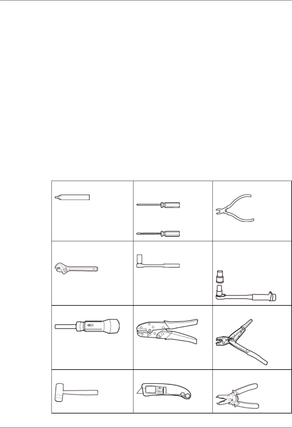
2.2 Tools and Instruments
This section lists the tools and instruments that must be obtained before the installation.
Marker Phillips screwdriver (M4,
M5, M6, M8)
Flat-head screwdriver (M4,
M5, M6, M8)
Diagonal pliers
Adjustable wrench (size ≤ 19
mm or 0.75 in.)
Socket wrench (M10, M12) Torque socket (30 N·m to 50
N·m or 265.52 lbf·in. to
442.54 lbf·in.)
Torque screwdriver COAX crimping tool Wire clippers
Rubber mallet Utility knife Wire stripper
DBS3900 (ICR)
Installation Guide 2 Installation Preparations
Issue 12 (2015-04-30) Huawei Proprietary and Confidential
Copyright © Huawei Technologies Co., Ltd.
7
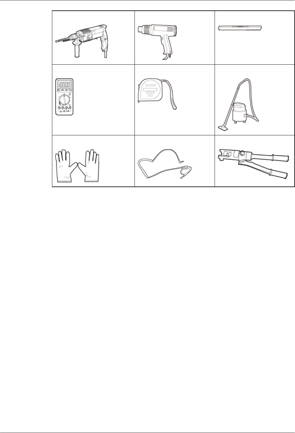
Hammer drill (Φ16) Heat gun Level
Multimeter Measuring tape Vacuum cleaner
ESD gloves ESD wrist strap Hydraulic pliers
2.3 Skills and Requirements for Onsite Personnel
Onsite personnel must be qualified and trained. Before performing any operation, onsite
personnel must be familiar with correct operation methods and safety precautions.
Before the installation, pay attention to the following items:
lThe customer's technical engineers must be trained by Huawei and be familiar with the
proper installation and operation methods.
lThe number of onsite personnel depends on the engineering schedule and installation
environment. Generally, only three to five onsite personnel are necessary.
DBS3900 (ICR)
Installation Guide 2 Installation Preparations
Issue 12 (2015-04-30) Huawei Proprietary and Confidential
Copyright © Huawei Technologies Co., Ltd.
8

3 Information to Be Known Before the
Installation
About This Chapter
This chapter describes the information about the installation, including exteriors, installation
scenarios, and clearance requirements.
3.1 Introduction to the Equipment
This section describes the devices involved in the DBS3900 installation.
3.2 Installation Scenarios
This section describes ICR installation scenarios.
3.3 Requirements for Dimensions and Clearances
This section describes the requirements for dimensions and clearances of devices to be installed.
DBS3900 (ICR)
Installation Guide 3 Information to Be Known Before the Installation
Issue 12 (2015-04-30) Huawei Proprietary and Confidential
Copyright © Huawei Technologies Co., Ltd.
9
3.1 Introduction to the Equipment
This section describes the devices involved in the DBS3900 installation.
NOTE
An indoor centralized rack (ICR) consists of an IFS06 and an IMB03:
lAn IFS06 is a type of indoor floor installation support (IFS).
lAn IMB03 is a type of indoor mini box.
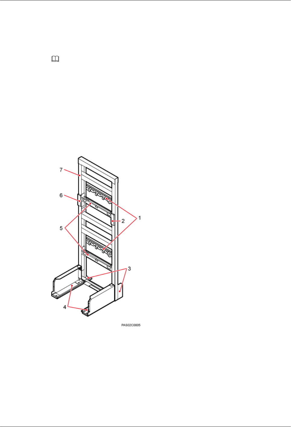
IFS06
An IFS06 is an indoor floor installation support. It is used for installing the IMB03 and RRUs
in a centralized manner. Figure 3-1 shows an IFS06.
Figure 3-1 IFS06
(1) Cable tray (2) Ground bar 2 (3) Rear foot (4) Front foot
(5) Adjustable beam (6) Ground bar 1 (7) Main frame -
IMB03
An IMB03 is an indoor mini box. It is used for installing the BBU and power devices. Figure
3-2 shows an IMB03.
DBS3900 (ICR)
Installation Guide 3 Information to Be Known Before the Installation
Issue 12 (2015-04-30) Huawei Proprietary and Confidential
Copyright © Huawei Technologies Co., Ltd.
10
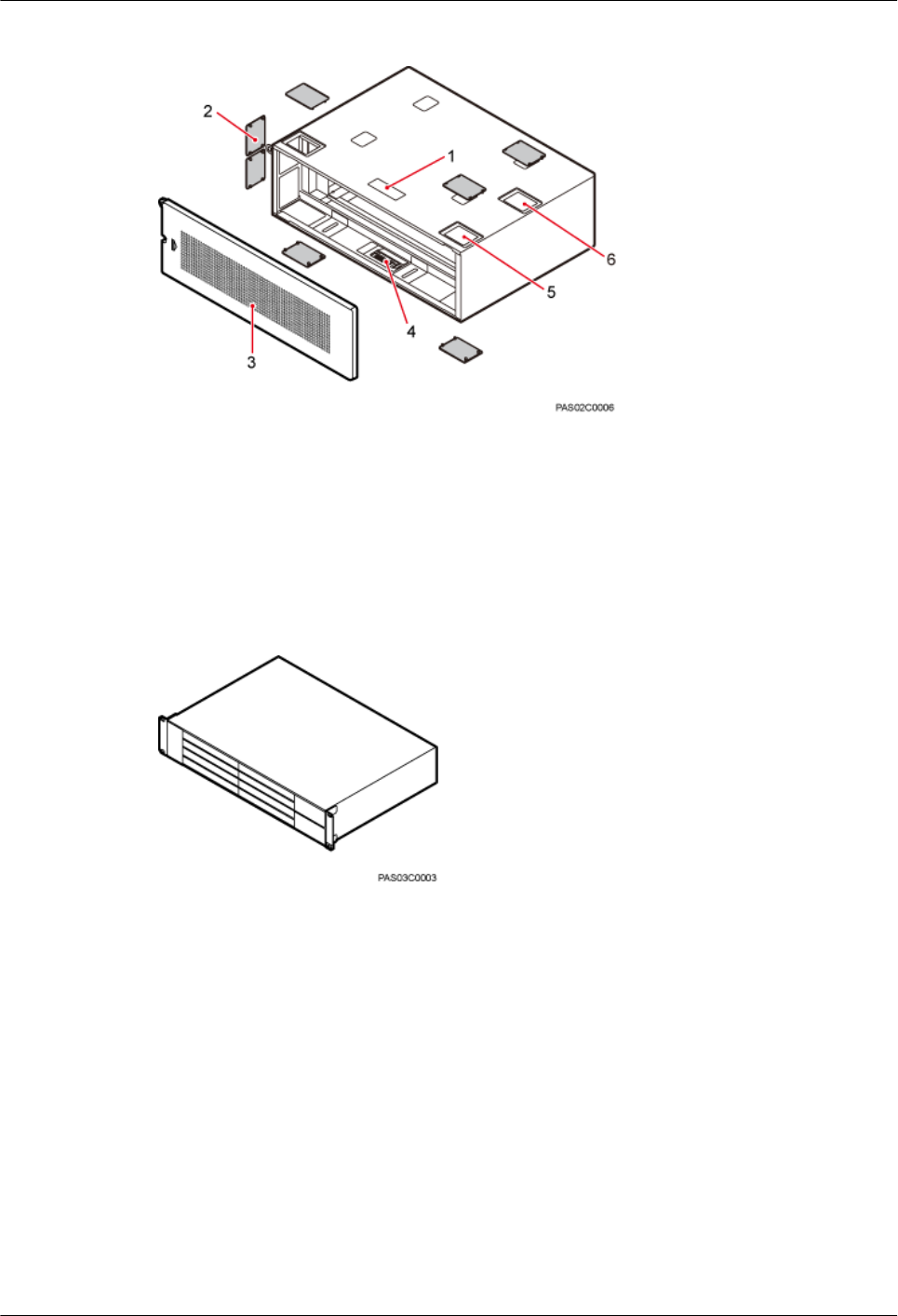
Figure 3-2 IMB03
(1) NO STEPPING sign (2) Protective plate (3) Cover plate
(4) Slot assignment label (5) Cable outlet (6) Dust disposal vent
Figure 3-3 shows a BBU.
Figure 3-3 BBU
Power devices are the DCDU-03B, DCDU-11B, and AC/DC and DC/DC power devices. Figure
3-4 shows a DCDU-03B. Figure 3-5 shows a DCDU-11B. Figure 3-6 shows an AC/DC power
device. Figure 3-7 shows a DC/DC power device.
DBS3900 (ICR)
Installation Guide 3 Information to Be Known Before the Installation
Issue 12 (2015-04-30) Huawei Proprietary and Confidential
Copyright © Huawei Technologies Co., Ltd.
11
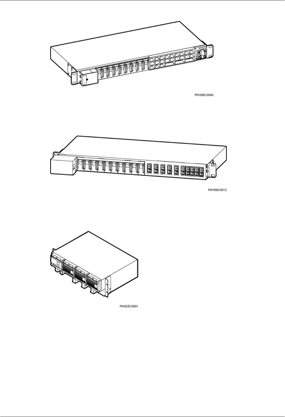
Figure 3-4 DCDU-03B
Figure 3-5 DCDU-11B
Figure 3-6 AC/DC power device
DBS3900 (ICR)
Installation Guide 3 Information to Be Known Before the Installation
Issue 12 (2015-04-30) Huawei Proprietary and Confidential
Copyright © Huawei Technologies Co., Ltd.
12
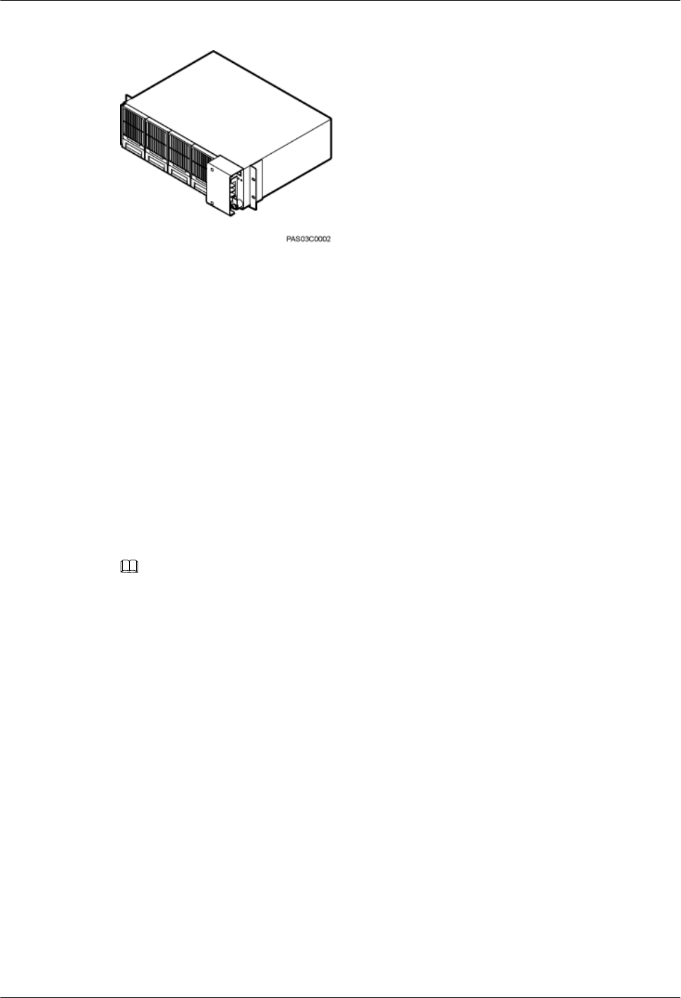
Figure 3-7 DC/DC power device
3.2 Installation Scenarios
This section describes ICR installation scenarios.
3.2.1 Installation Scenarios
The ICR installation options vary according to height-restricted and height-unrestricted
scenarios.
In the scenario where a cable tray is 1.8 m to 2 m (5.91 ft to 6.56 ft) above the floor (referred to
as the height-restricted scenario), RRUs are installed on beam 2 and beam 4, as shown in Figure
3-8.
NOTE
lIn height-restricted scenarios, the adjustable beams need to be moved to the position marked 1.8 m
(5.91 ft).
lWhen RRUs are installed on beam 1 or 2, they are installed at the upper layer.
lWhen RRUs are installed on beam 3 or 4, they are installed at the lower layer.
DBS3900 (ICR)
Installation Guide 3 Information to Be Known Before the Installation
Issue 12 (2015-04-30) Huawei Proprietary and Confidential
Copyright © Huawei Technologies Co., Ltd.
13
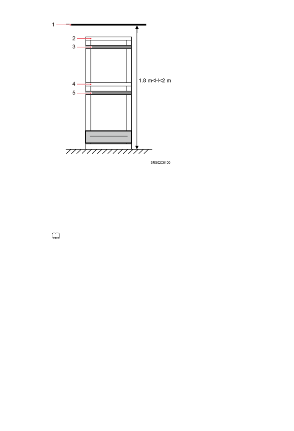
Figure 3-8 Height-restricted scenarios
(1) Cable tray (2) Beam 1 (3) Beam 2 (4) Beam 3 (5) Beam 4
In the scenario where a cable tray is higher than 2 m (6.56 ft) above the floor (referred to as the
height-unrestricted scenario), RRUs are installed on beam 1 and beam 3, as shown in Figure
3-9.
NOTE
lWhen RRUs are installed on beam 1 or 2, they are installed at the upper layer.
lWhen RRUs are installed on beam 3 or 4, they are installed at the lower layer.
DBS3900 (ICR)
Installation Guide 3 Information to Be Known Before the Installation
Issue 12 (2015-04-30) Huawei Proprietary and Confidential
Copyright © Huawei Technologies Co., Ltd.
14
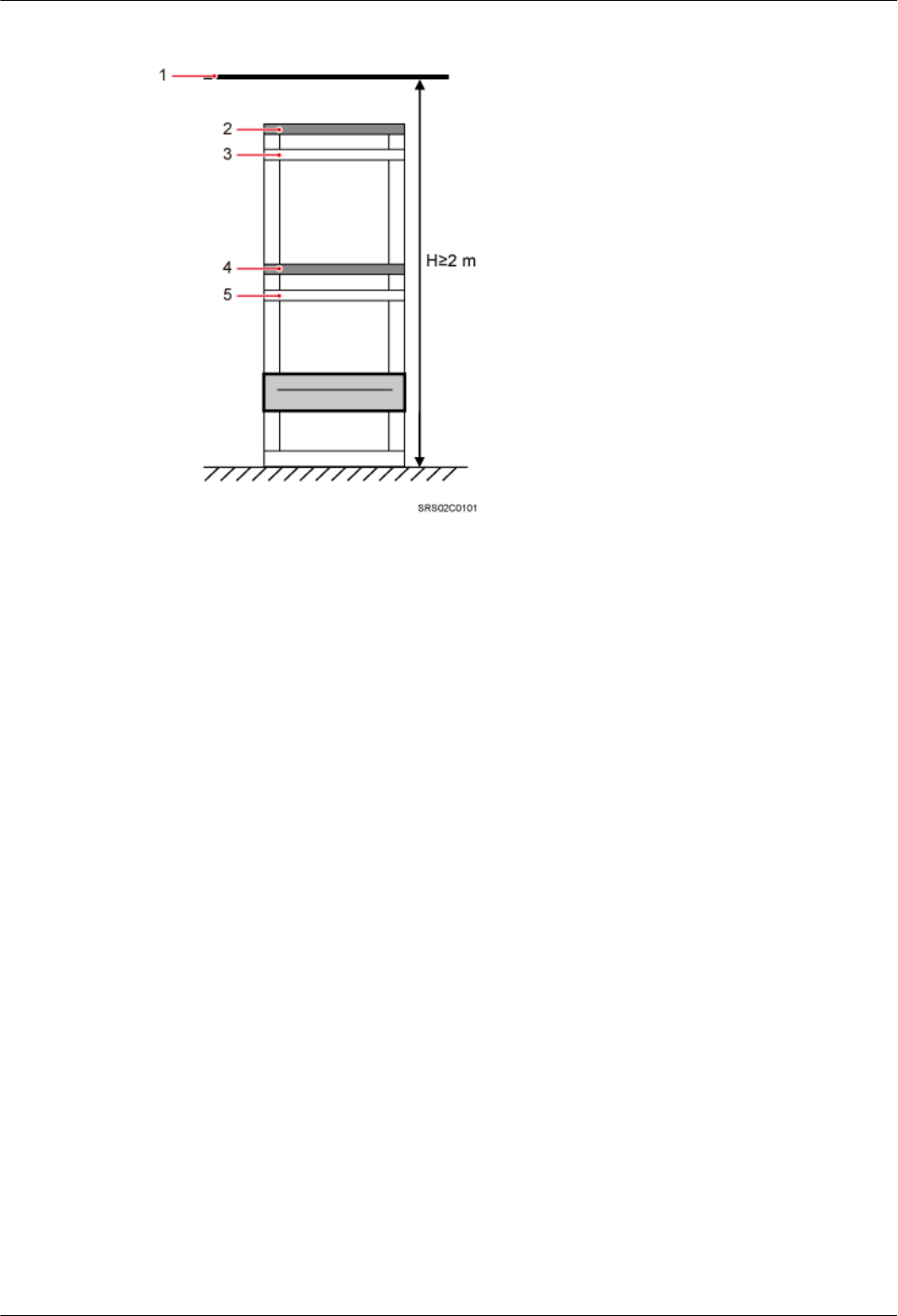
Figure 3-9 Height-unrestricted scenarios
(1) Cable tray (2) Beam 1 (3) Beam 2 (4) Beam 3 (4) Beam 4
3.2.2 Height-Restricted Scenarios
This section describes the height-restricted scenarios for installing the DBS3900 on an ICR.
Height-Restricted Scenarios (-48 V DC)
This section describes the height-restricted scenarios with external -48 V DC power supply. In
these scenarios, DC RRUs can be installed together with an IMB03 on an IFS06 or independently
on an IFS06.
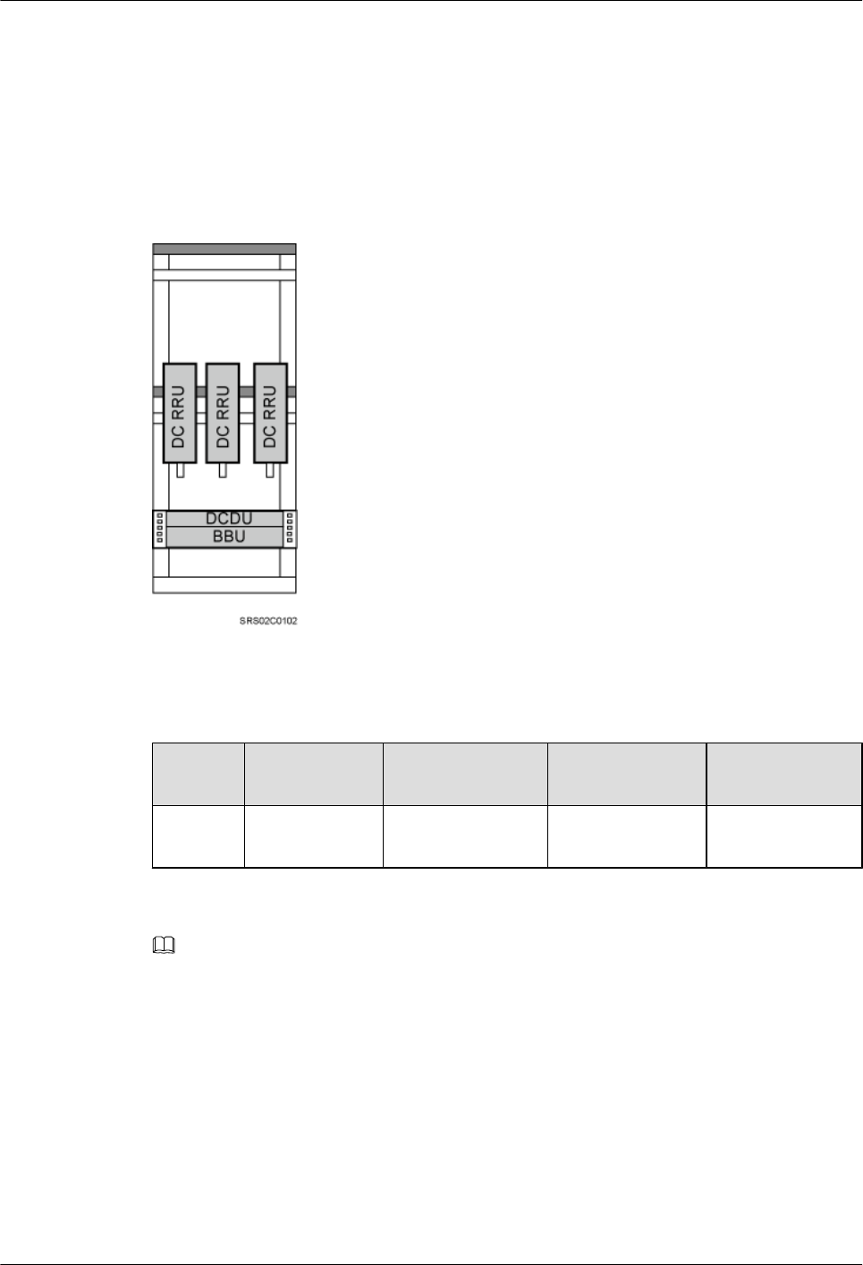
DC RRUs and IMB03 Installed Together (IFS06+IMB03+DC RRUs)
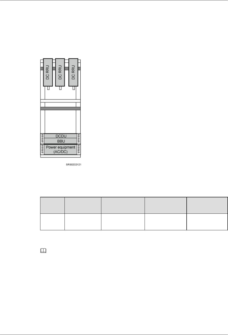
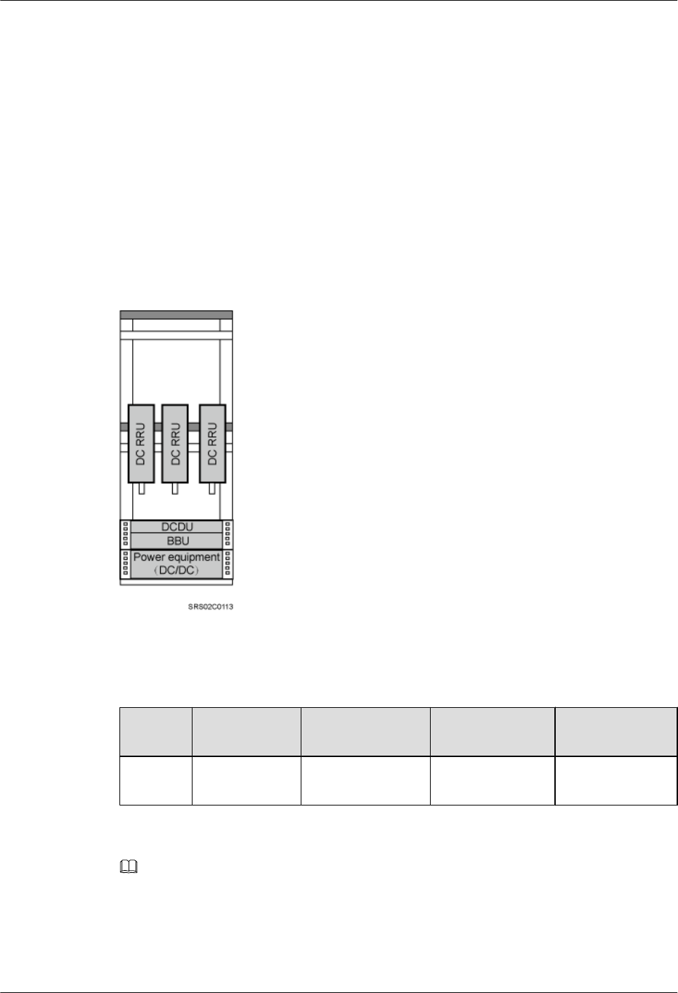
In this scenario, a single IFS06 supports a maximum of six DC RRUs, and a single site supports
a maximum of 12 DC RRUs. When only three DC RRUs need to be installed, they are installed
at the lower layer.
l1 IFS06+1 IMB03+3 DC RRUs
DBS3900 (ICR)
Installation Guide 3 Information to Be Known Before the Installation
Issue 12 (2015-04-30) Huawei Proprietary and Confidential
Copyright © Huawei Technologies Co., Ltd.
15
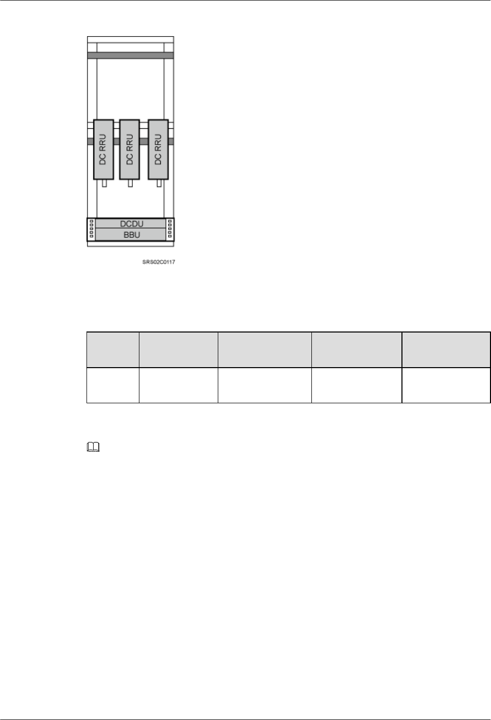
Figure 3-10 1 IFS06+1 IMB03+3 DC RRUs
Table 3-1 3 DC RRUs
Position GSM UMTS LTE GSM+UMTS/
GSM+LTE
Lower
layer
3 RRU3008s 3 RRU3804s 3 RRU3201s 3 RRU3908s
NOTE
lRRU3008s are used as examples for RRUs in GSM mode.
lRRU3804s are used as examples for RRUs in UMTS mode.
lRRU3201s are used as examples for RRUs in LTE mode.
lRRU3908s are used as examples for RRUs in multiple modes.
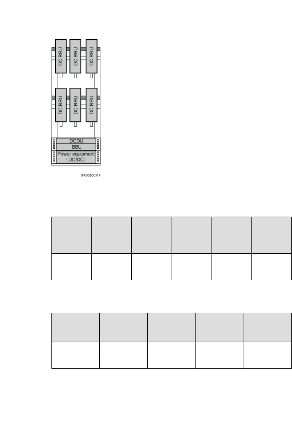
l1 IFS06+1 IMB03+6 DC RRUs
DBS3900 (ICR)
Installation Guide 3 Information to Be Known Before the Installation
Issue 12 (2015-04-30) Huawei Proprietary and Confidential
Copyright © Huawei Technologies Co., Ltd.
16
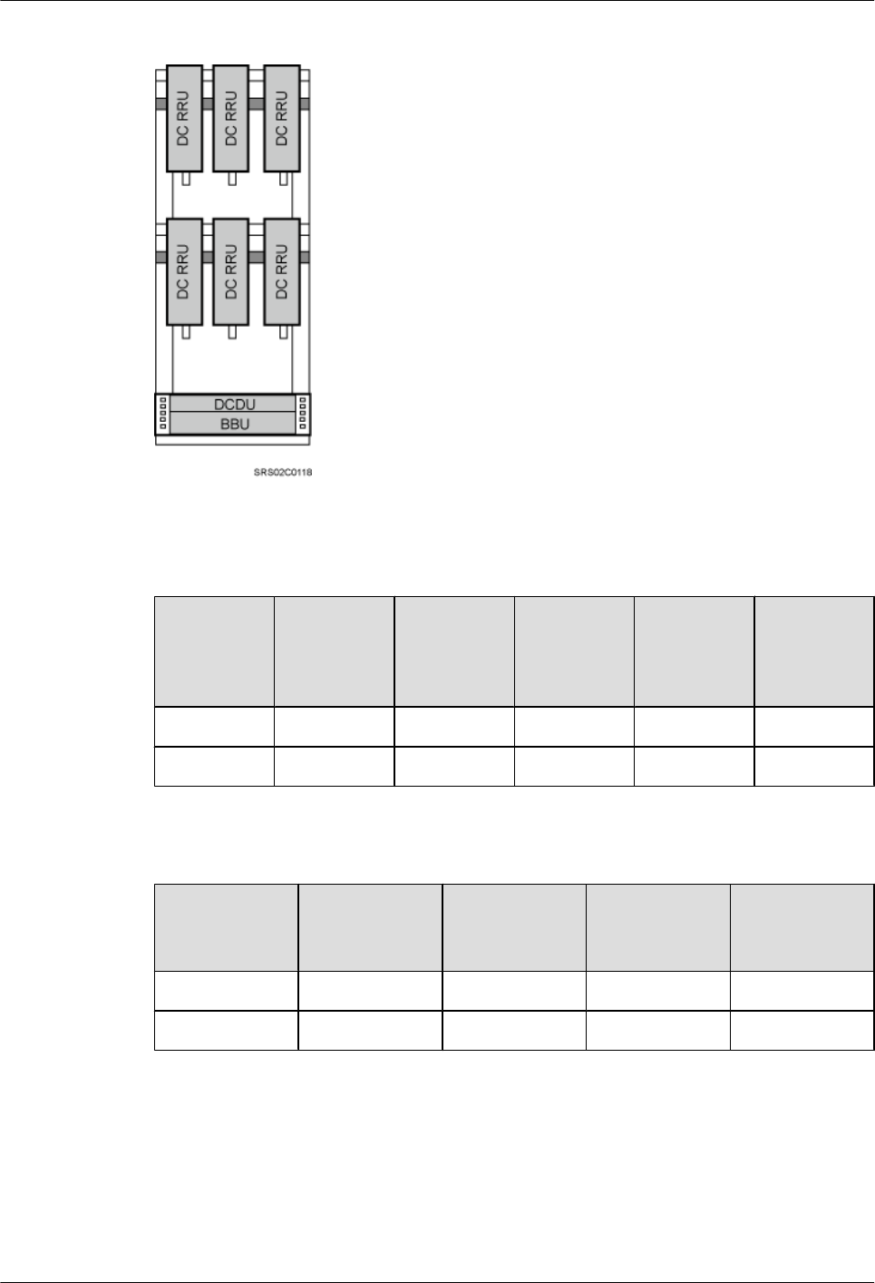
Figure 3-11 1 IFS06+1 IMB03+6 DC RRUs
Table 3-2 6 DC RRUs (in GSM/UMTS mode)
Position GSM UMTS GSM
+UMTS
Co-Cabinet
of GSM
+UMTS
and UMTS
Co-Cabinet
of GSM
and UMTS
Upper layer 3 RRU3008s 3 RRU3804s 3 RRU3908s 3 RRU3908s 3 RRU3008s
Lower layer 3 RRU3008s 3 RRU3804s 3 RRU3908s 3 RRU3804s 3 RRU3804s
Table 3-3 6 DC RRUs (in GSM/LTE mode)
Position GSM LTE Co-Cabinet of
GSM+LTE
and LTE
Co-Cabinet of
GSM and LTE
Upper layer 3 RRU3008s 3 RRU3201s 3 RRU3908s 3 RRU3008s
Lower layer 3 RRU3008s 3 RRU3201s 3 RRU3201s 3 RRU3201s
DBS3900 (ICR)
Installation Guide 3 Information to Be Known Before the Installation
Issue 12 (2015-04-30) Huawei Proprietary and Confidential
Copyright © Huawei Technologies Co., Ltd.
17
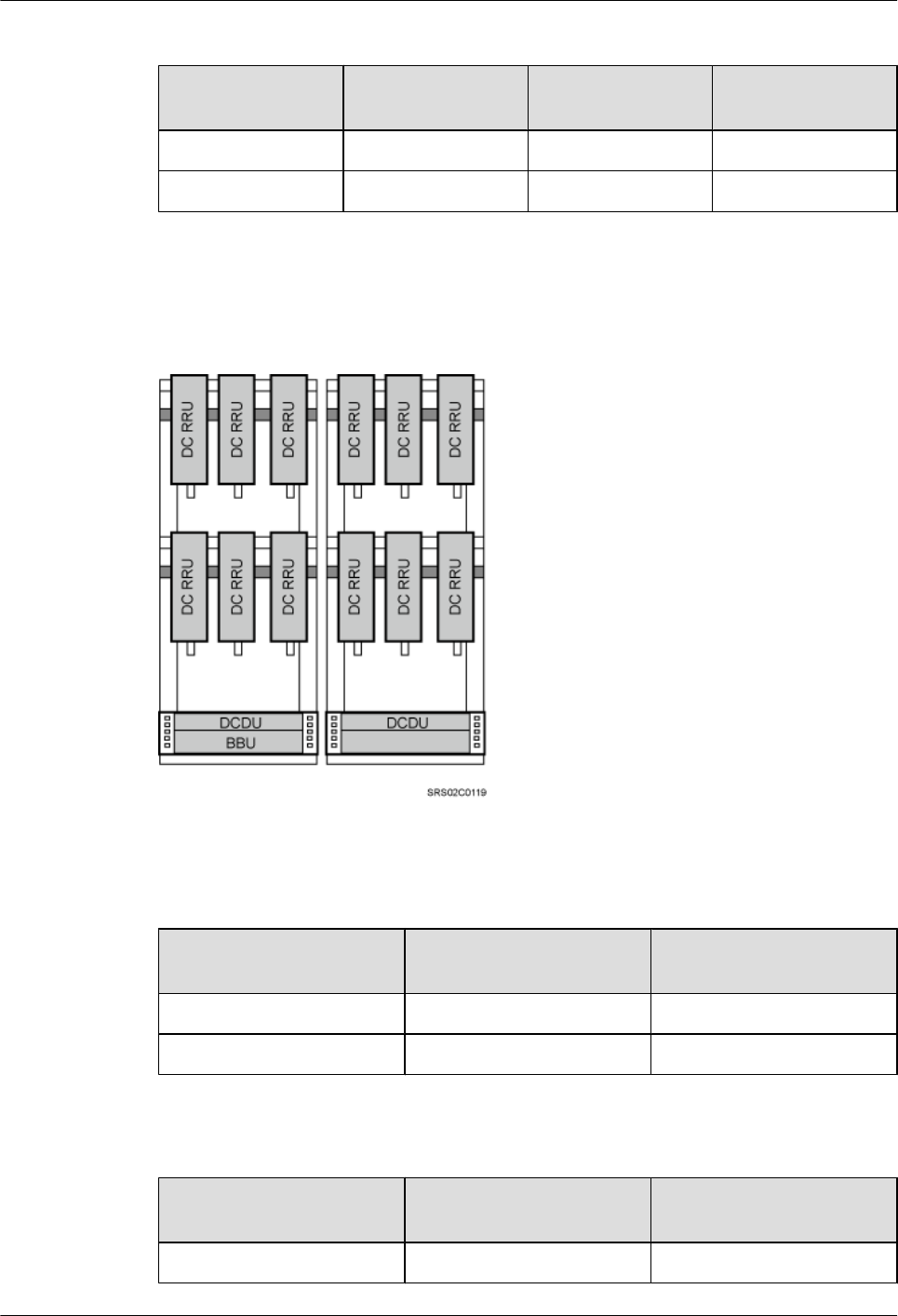
Table 3-4 6 DC RRUs (in UMTS/LTE mode)
Position UMTS LTE Co-Cabinet of
UMTS and LTE
Upper layer 3 RRU3804s 3 RRU3201s 3 RRU3804s
Lower layer 3 RRU3804s 3 RRU3201s 3 RRU3201s
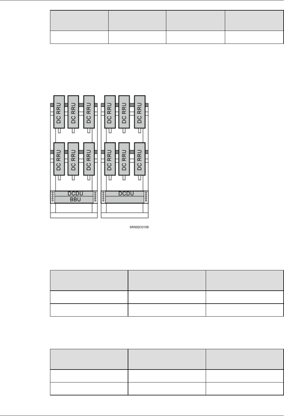
l2 IFS06s+2 IMB03s+12 DC RRUs
Figure 3-12 2 IFS06s+2 IMB03s+12 DC RRUs
Table 3-5 12 DC RRUs (in GSM/UMTS mode)
Position Co-Cabinet of GSM
+UMTS and UMTS
Co-Cabinet of GSM and
UMTS
ICR 1 6 RRU3908s 6 RRU3008s
ICR 2 6 RRU3804s 6 RRU3804s
Table 3-6 12 DC RRUs (in GSM/LTE mode)
Position Co-Cabinet of GSM+LTE
and LTE
Co-Cabinet of GSM and
LTE
ICR 1 6 RRU3908s 6 RRU3008s
DBS3900 (ICR)
Installation Guide 3 Information to Be Known Before the Installation
Issue 12 (2015-04-30) Huawei Proprietary and Confidential
Copyright © Huawei Technologies Co., Ltd.
18
Position Co-Cabinet of GSM+LTE
and LTE
Co-Cabinet of GSM and
LTE
ICR 2 6 RRU3201s 6 RRU3201s
Table 3-7 12 DC RRUs (in UMTS/LTE mode)
Position Co-Cabinet of UMTS and LTE
ICR 1 6 RRU3804s
ICR 2 6 RRU3201s
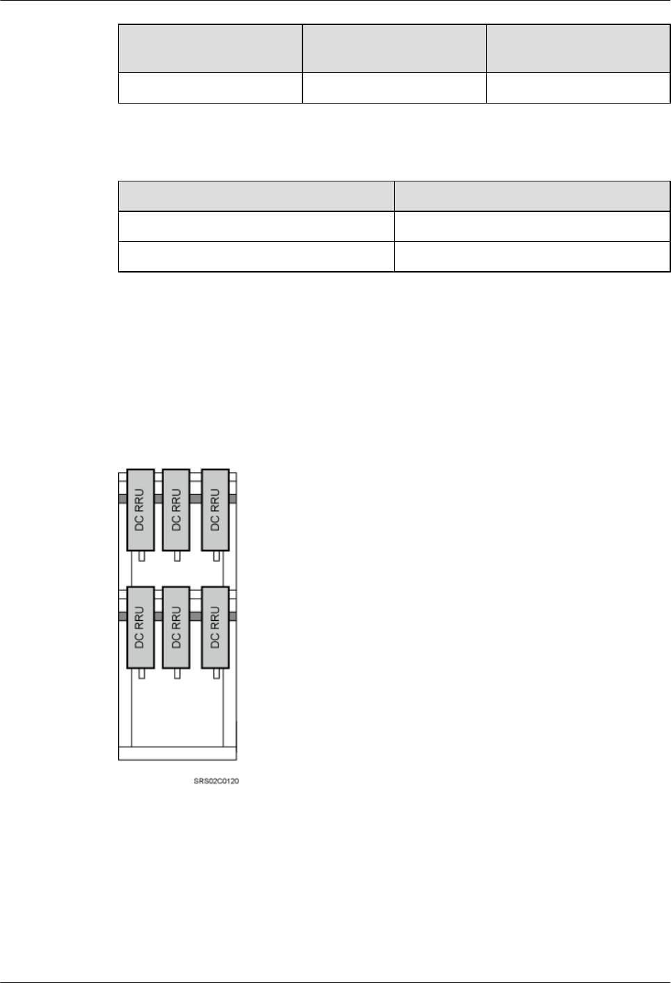
DC RRUs Installed Independently (IFS06+DC RRUs)
In this scenario, a single IFS06 supports three or six DC RRUs. Figure 3-13 shows the scenario
where six DC RRUs are installed. When only three DC RRUs need to be installed, they are
installed at the lower layer.
Figure 3-13 DC RRUs installed on the IFS06
Height-Restricted Scenarios (220 V AC)
This section describes the height-restricted scenarios with external 220 V AC power supply. In
these scenarios, RRUs can be installed together with an IMB03 on an IFS06 or independently
on an IFS06.
DBS3900 (ICR)
Installation Guide 3 Information to Be Known Before the Installation
Issue 12 (2015-04-30) Huawei Proprietary and Confidential
Copyright © Huawei Technologies Co., Ltd.
19
DC RRUs and IMB03 Installed Together (IFS06+IMB03+DC RRUs)
In this scenario, a single IFS06 supports a maximum of three DC RRUs, and a single site supports
a maximum of six DC RRUs.
l1 IFS06+2 IMB03s+3 DC RRUs
Figure 3-14 1 IFS06+2 IMB03s+3 DC RRUs
Table 3-8 3 DC RRUs
Position GSM UMTS LTE GSM+UMTS/
GSM+LTE
Upper
layer
3 RRU3008s 3 RRU3804s 3 RRU3201s 3 RRU3908s
NOTE
lRRU3008s are used as examples for RRUs in GSM mode.
lRRU3804s are used as examples for RRUs in UMTS mode.
lRRU3201s are used as examples for RRUs in LTE mode.
lRRU3908s are used as examples for RRUs in multiple modes.
l2 IFS06s+2 IMB03s+6 DC RRUs
DBS3900 (ICR)
Installation Guide 3 Information to Be Known Before the Installation
Issue 12 (2015-04-30) Huawei Proprietary and Confidential
Copyright © Huawei Technologies Co., Ltd.
20
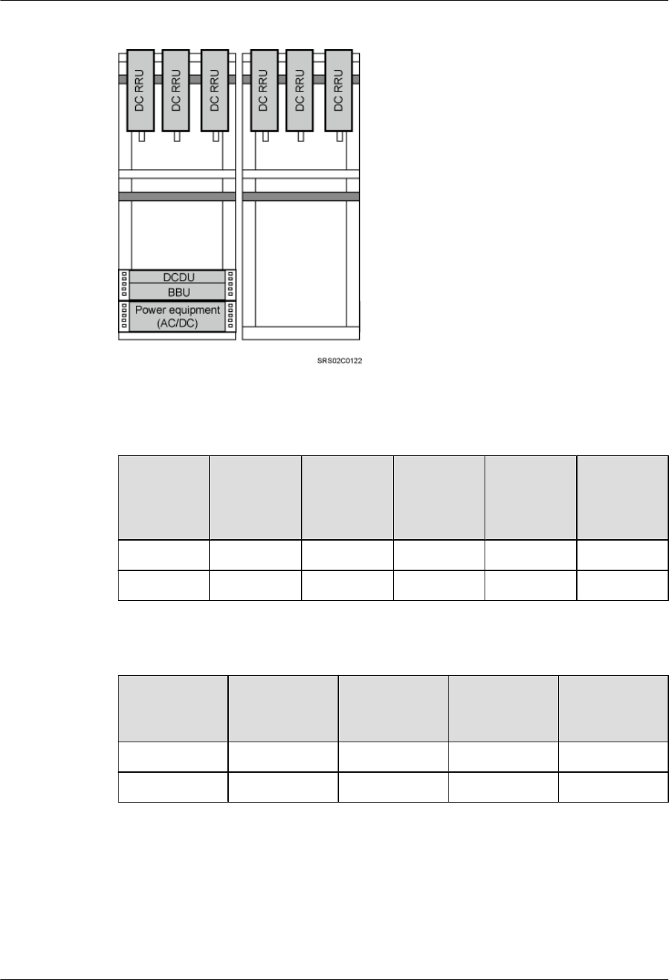
Figure 3-15 2 IFS06s+2 IMB03s+6 DC RRUs
Table 3-9 6 DC RRUs (in GSM/UMTS mode)
Position GSM UMTS GSM
+UMTS
Co-Cabinet
of GSM
+UMTS
and UMTS
Co-Cabinet
of GSM
and UMTS
ICR 1 3 RRU3008s 3 RRU3804s 3 RRU3908s 3 RRU3908s 3 RRU3008s
ICR 2 3 RRU3008s 3 RRU3804s 3 RRU3908s 3 RRU3804s 3 RRU3804s
Table 3-10 6 DC RRUs (in GSM/LTE mode)
Position GSM LTE Co-Cabinet of
GSM+LTE
and LTE
Co-Cabinet of
GSM and LTE
ICR 1 3 RRU3008s 3 RRU3201s 3 RRU3908s 3 RRU3008s
ICR 2 3 RRU3008s 3 RRU3201s 3 RRU3201s 3 RRU3201s
DBS3900 (ICR)
Installation Guide 3 Information to Be Known Before the Installation
Issue 12 (2015-04-30) Huawei Proprietary and Confidential
Copyright © Huawei Technologies Co., Ltd.
21
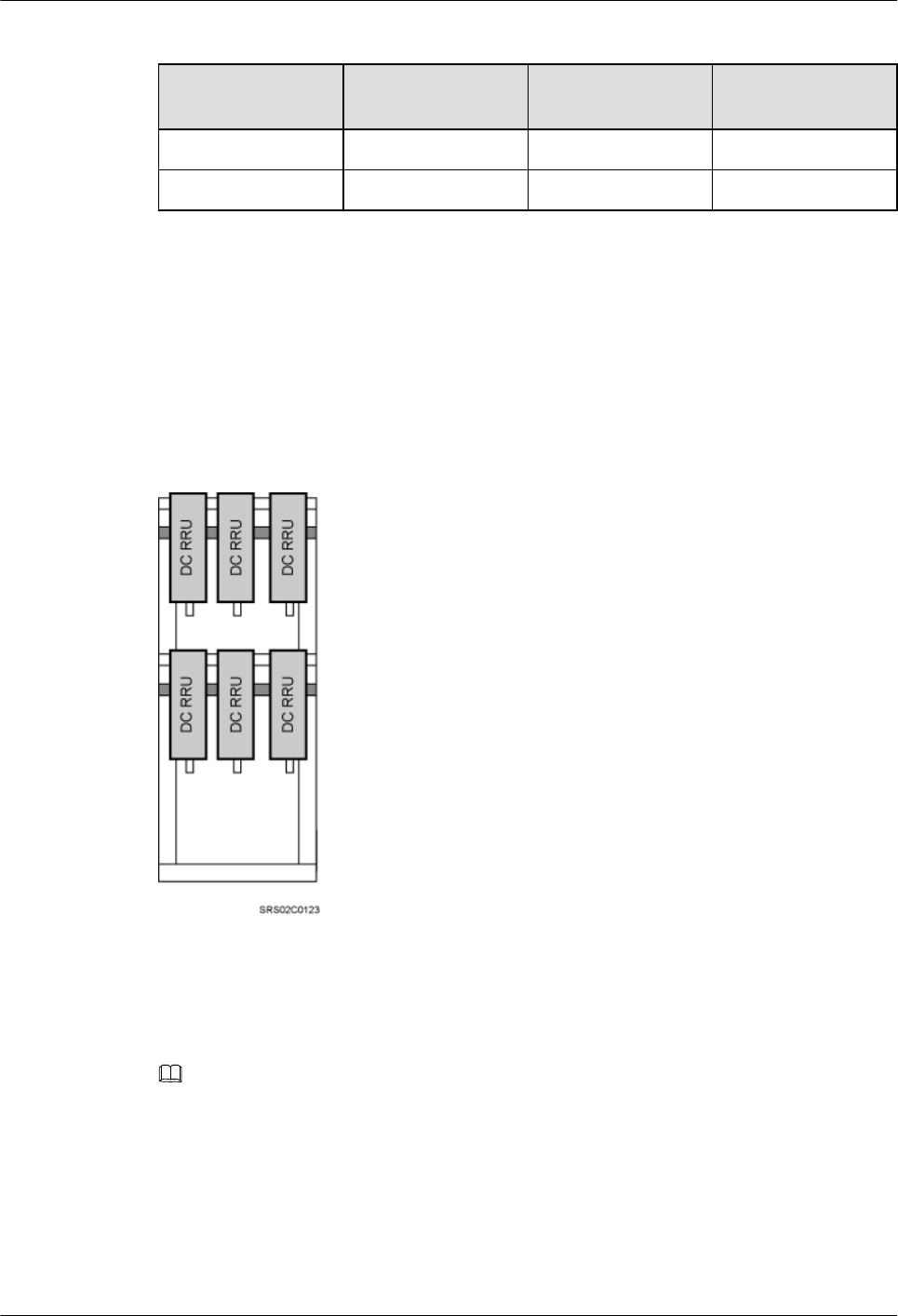
Table 3-11 6 DC RRUs (in UMTS/LTE mode)
Position UMTS LTE Co-Cabinet of
UMTS and LTE
ICR 1 3 RRU3804s 3 RRU3201s 3 RRU3804s
ICR 2 3 RRU3804s 3 RRU3201s 3 RRU3201s
RRUs Installed Independently (IFS06+RRUs)
l1 IFS06+6 DC RRUs
In this scenario, a single IFS06 supports three or six DC RRUs. Figure 3-16 shows the scenario
where six DC RRUs are installed. When only three DC RRUs need to be installed, they are
installed at the upper layer.
Figure 3-16 DC RRUs installed on the IFS06
l1 IFS06+2 AC RRUs
In this scenario, a single IFS06 supports a maximum two AC RRUs, as shown in Figure 3-17.
NOTE
This document uses AC RRU3908s as examples.
DBS3900 (ICR)
Installation Guide 3 Information to Be Known Before the Installation
Issue 12 (2015-04-30) Huawei Proprietary and Confidential
Copyright © Huawei Technologies Co., Ltd.
22

Figure 3-17 AC RRUs installed on the IFS06
Height-Restricted Scenarios (+24 V DC)
This section describes the height-restricted scenarios with external +24 V DC power supply. In
these scenarios, DC RRUs can be installed together with an IMB03 on an IFS06 or independently
on an IFS06.
DC RRUs and IMB03 Installed Together (IFS06+IMB03+DC RRUs)
In this scenario, a single IFS06 supports a maximum of three DC RRUs, and a single site supports
a maximum of six DC RRUs.
l1 IFS06+2 IMB03s+3 DC RRUs
DBS3900 (ICR)
Installation Guide 3 Information to Be Known Before the Installation
Issue 12 (2015-04-30) Huawei Proprietary and Confidential
Copyright © Huawei Technologies Co., Ltd.
23
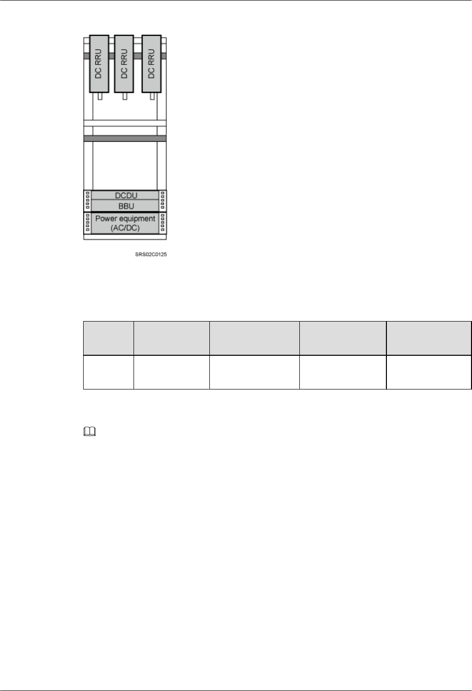
Figure 3-18 1 IFS06+2 IMB03s+3 DC RRUs
Table 3-12 3 DC RRUs
Position GSM UMTS LTE GSM+UMTS/
GSM+LTE
Upper
layer
3 RRU3008s 3 RRU3804s 3 RRU3201s 3 RRU3908s
NOTE
lRRU3008s are used as examples for RRUs in GSM mode.
lRRU3804s are used as examples for RRUs in UMTS mode.
lRRU3201s are used as examples for RRUs in LTE mode.
lRRU3908s are used as examples for RRUs in multiple modes.
l2 IFS06s+2 IMB03s+6 DC RRUs
DBS3900 (ICR)
Installation Guide 3 Information to Be Known Before the Installation
Issue 12 (2015-04-30) Huawei Proprietary and Confidential
Copyright © Huawei Technologies Co., Ltd.
24

Figure 3-19 2 IFS06s+2 IMB03s+6 DC RRUs
Table 3-13 6 DC RRUs (in GSM/UMTS mode)
Position GSM UMTS GSM
+UMTS
Co-Cabinet
of GSM
+UMTS
and UMTS
Co-Cabinet
of GSM
and UMTS
ICR 1 3 RRU3008s 3 RRU3804s 3 RRU3908s 3 RRU3908s 3 RRU3008s
ICR 2 3 RRU3008s 3 RRU3804s 3 RRU3908s 3 RRU3804s 3 RRU3804s
Table 3-14 6 DC RRUs (in GSM/LTE mode)
Position GSM LTE Co-Cabinet of
GSM+LTE
and LTE
Co-Cabinet of
GSM and LTE
ICR 1 3 RRU3008s 3 RRU3201s 3 RRU3908s 3 RRU3008s
ICR 2 3 RRU3008s 3 RRU3201s 3 RRU3201s 3 RRU3201s
DBS3900 (ICR)
Installation Guide 3 Information to Be Known Before the Installation
Issue 12 (2015-04-30) Huawei Proprietary and Confidential
Copyright © Huawei Technologies Co., Ltd.
25
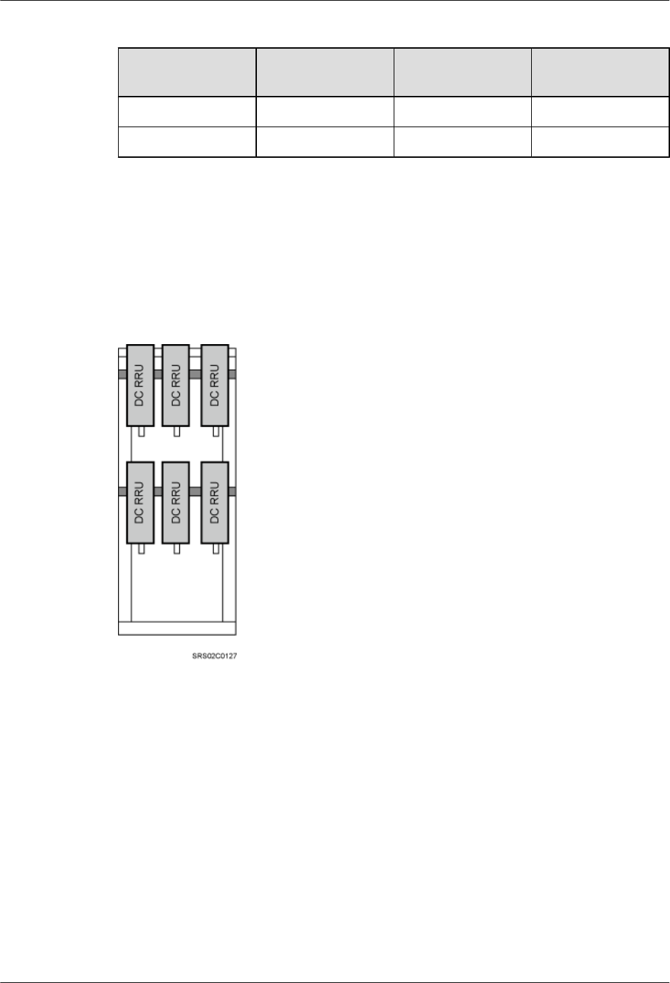
Table 3-15 6 DC RRUs (in UMTS/LTE mode)
Position UMTS LTE Co-Cabinet of
UMTS and LTE
ICR 1 3 RRU3804s 3 RRU3201s 3 RRU3804s
ICR 2 3 RRU3804s 3 RRU3201s 3 RRU3201s
DC RRUs Installed Independently (IFS06+DC RRUs)
In this scenario, a single IFS06 supports three or six DC RRUs. Figure 3-20 shows the scenario
where six DC RRUs are installed. When only three DC RRUs need to be installed, they are
installed at the upper layer.
Figure 3-20 DC RRUs installed on the IFS06
3.2.3 Height-Unrestricted Scenarios
This section describes the height-unrestricted scenarios for installing the DBS3900 on an ICR.
Height-Unrestricted Scenarios (-48 V DC)
This section describes the height-unrestricted scenarios with external -48 V DC power supply.
In these scenarios, DC RRUs can be installed together with an IMB03 on an IFS06 or
independently on an IFS06.
DBS3900 (ICR)
Installation Guide 3 Information to Be Known Before the Installation
Issue 12 (2015-04-30) Huawei Proprietary and Confidential
Copyright © Huawei Technologies Co., Ltd.
26
DC RRUs and IMB03 Installed Together (IFS06+IMB03+DC RRUs)
In single- or dual-mode scenarios, a single IFS06 supports a maximum of six DC RRUs, and a
single site supports a maximum of 12 DC RRUs. When only three DC RRUs need to be installed,
they are installed at the lower layer.
l1 IFS06+1 IMB03+3 DC RRUs
Figure 3-21 1 IFS06+1 IMB03+3 DC RRUs
Table 3-16 3 DC RRUs
Position GSM UMTS LTE GSM+UMTS/
GSM+LTE
Lower
layer
3 RRU3008s 3 RRU3804s 3 RRU3201s 3 RRU3908s
NOTE
lRRU3008s are used as examples for RRUs in GSM mode.
lRRU3804s are used as examples for RRUs in UMTS mode.
lRRU3201s are used as examples for RRUs in LTE mode.
lRRU3908s are used as examples for RRUs in multiple modes.
l1 IFS06+1 IMB03+6 DC RRUs
DBS3900 (ICR)
Installation Guide 3 Information to Be Known Before the Installation
Issue 12 (2015-04-30) Huawei Proprietary and Confidential
Copyright © Huawei Technologies Co., Ltd.
27
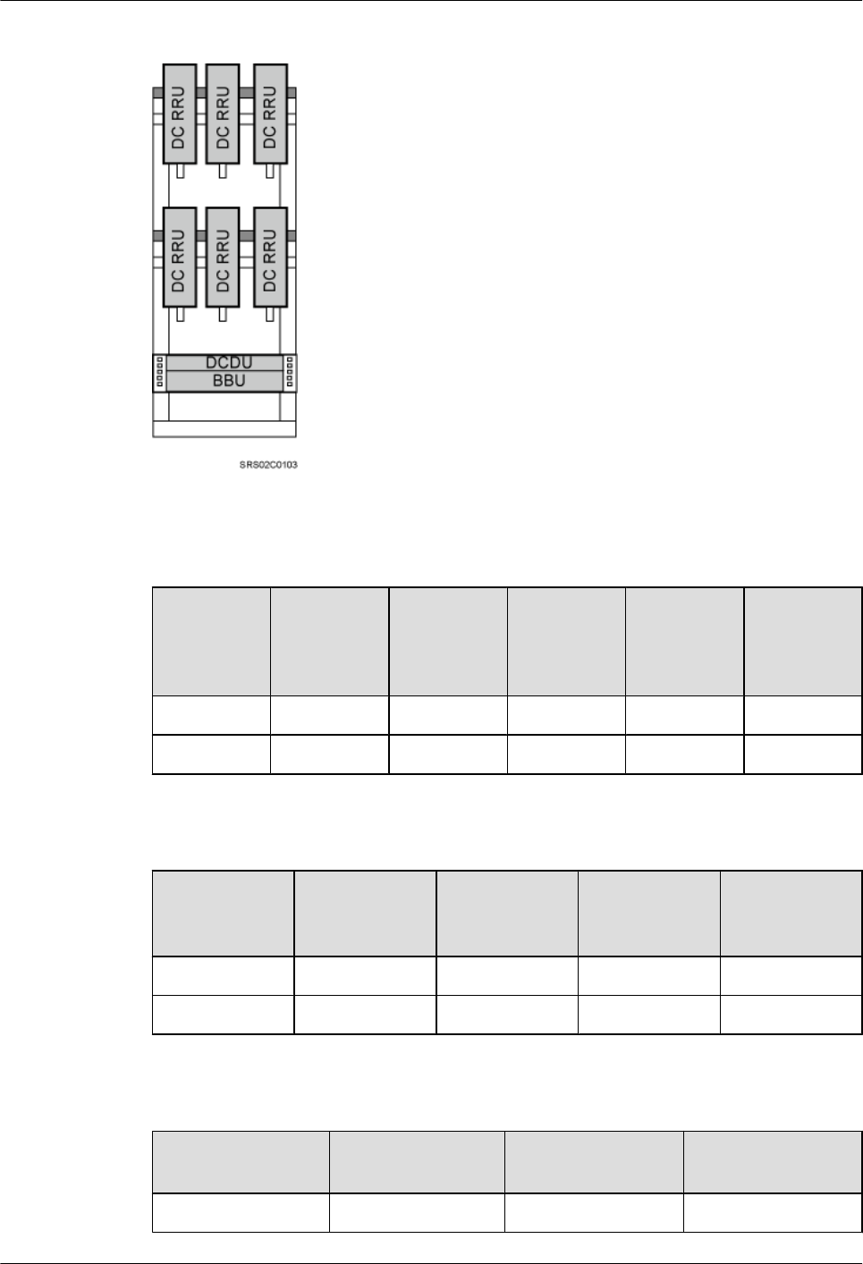
Figure 3-22 1 IFS06+1 IMB03+6 DC RRUs
Table 3-17 6 DC RRUs (in GSM/UMTS mode)
Position GSM UMTS GSM
+UMTS
Co-Cabinet
of GSM
+UMTS
and UMTS
Co-Cabinet
of GSM
and UMTS
Upper layer 3 RRU3008s 3 RRU3804s 3 RRU3908s 3 RRU3908s 3 RRU3008s
Lower layer 3 RRU3008s 3 RRU3804s 3 RRU3908s 3 RRU3804s 3 RRU3804s
Table 3-18 6 DC RRUs (in GSM/LTE mode)
Position GSM LTE Co-Cabinet of
GSM+LTE
and LTE
Co-Cabinet of
GSM and LTE
Upper layer 3 RRU3008s 3 RRU3201s 3 RRU3908s 3 RRU3008s
Lower layer 3 RRU3008s 3 RRU3201s 3 RRU3201s 3 RRU3201s
Table 3-19 6 DC RRUs (in UMTS/LTE mode)
Position UMTS LTE Co-Cabinet of
UMTS and LTE
Upper layer 3 RRU3804s 3 RRU3201s 3 RRU3804s
DBS3900 (ICR)
Installation Guide 3 Information to Be Known Before the Installation
Issue 12 (2015-04-30) Huawei Proprietary and Confidential
Copyright © Huawei Technologies Co., Ltd.
28
Position UMTS LTE Co-Cabinet of
UMTS and LTE
Lower layer 3 RRU3804s 3 RRU3201s 3 RRU3201s
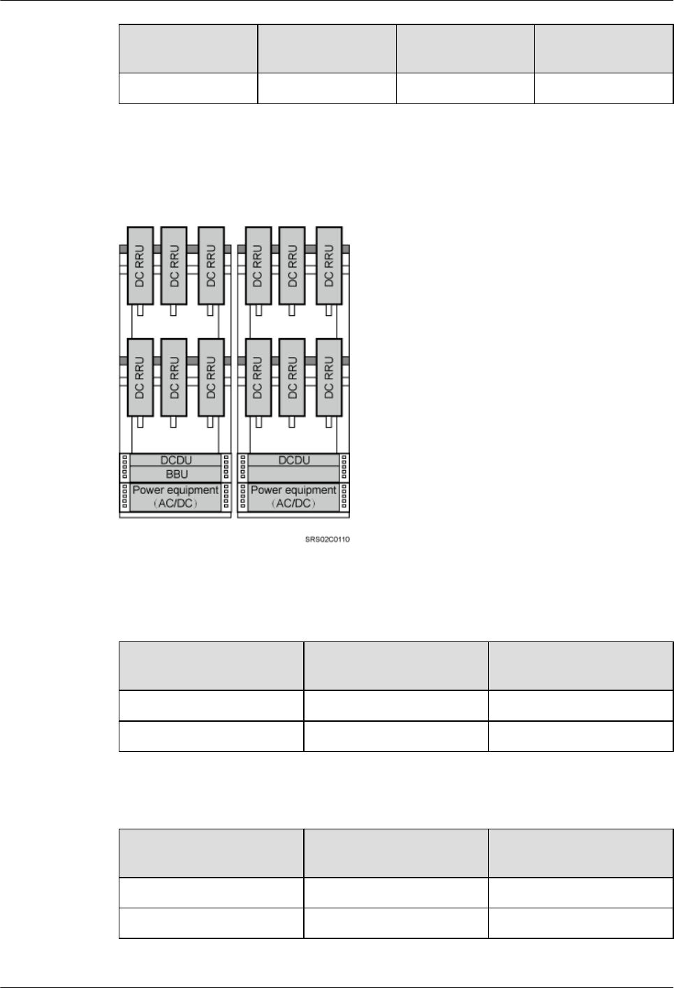
l2 IFS06s+2 IMB03s+12 DC RRUs
Figure 3-23 2 IFS06s+2 IMB03s+12 DC RRUs
Table 3-20 12 DC RRUs (in GSM/UMTS mode)
Position Co-Cabinet of GSM
+UMTS and UMTS
Co-Cabinet of GSM and
UMTS
ICR 1 6 RRU3908s 6 RRU3008s
ICR 2 6 RRU3804s 6 RRU3804s
Table 3-21 12 DC RRUs (in GSM/LTE mode)
Position Co-Cabinet of GSM
+UMTS and UMTS
Co-Cabinet of GSM and
UMTS
ICR 1 6 RRU3908s 6 RRU3008s
ICR 2 6 RRU3201s 6 RRU3201s
DBS3900 (ICR)
Installation Guide 3 Information to Be Known Before the Installation
Issue 12 (2015-04-30) Huawei Proprietary and Confidential
Copyright © Huawei Technologies Co., Ltd.
29
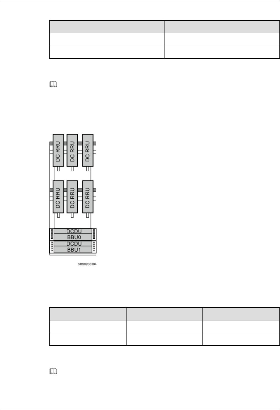
Table 3-22 12 DC RRUs (in UMTS/LTE mode)
Position Co-Cabinet of UMTS and LTE
ICR 1 6 RRU3804s
ICR 2 6 RRU3201s
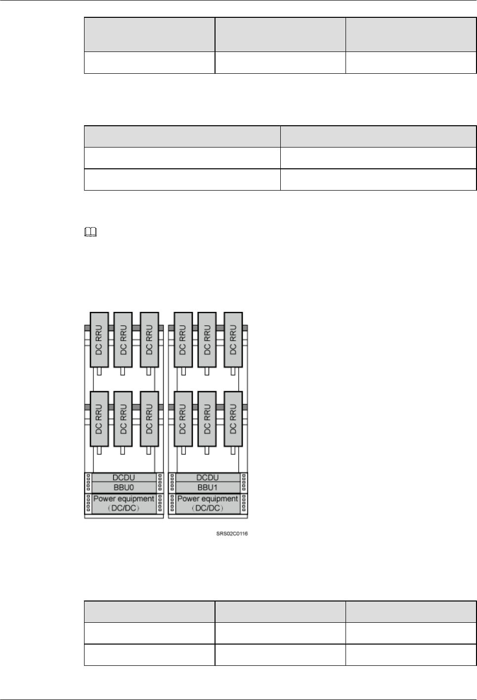
NOTE
In triple-mode scenarios, when only one ICR is used, two BBUs are installed separately in two IMB03s.
BBU 0 (primary BBU) is installed in the upper IMB03, and BBU 1 (secondary BBU) is installed in the
lower IMB03, as shown in Figure 3-24.
Figure 3-24 Triple-mode scenario (6 DC RRUs)
Table 3-23 6 DC RRUs (in GSM/UMTS/LTE mode)
Position GU+LTE GL+UMTS
Upper layer 3 RRU3908s 3 RRU3908s
Lower layer 3 RRU3201s 3 RRU3804s
NOTE
In triple-mode scenarios, when two ICRs are used, two BBUs are installed separately in two IMB03s. BBU
0 (primary BBU) is installed on the left IFS06, and BBU 1 (secondary BBU) is installed on the right IFS06,
as shown in Figure 3-25.
DBS3900 (ICR)
Installation Guide 3 Information to Be Known Before the Installation
Issue 12 (2015-04-30) Huawei Proprietary and Confidential
Copyright © Huawei Technologies Co., Ltd.
30
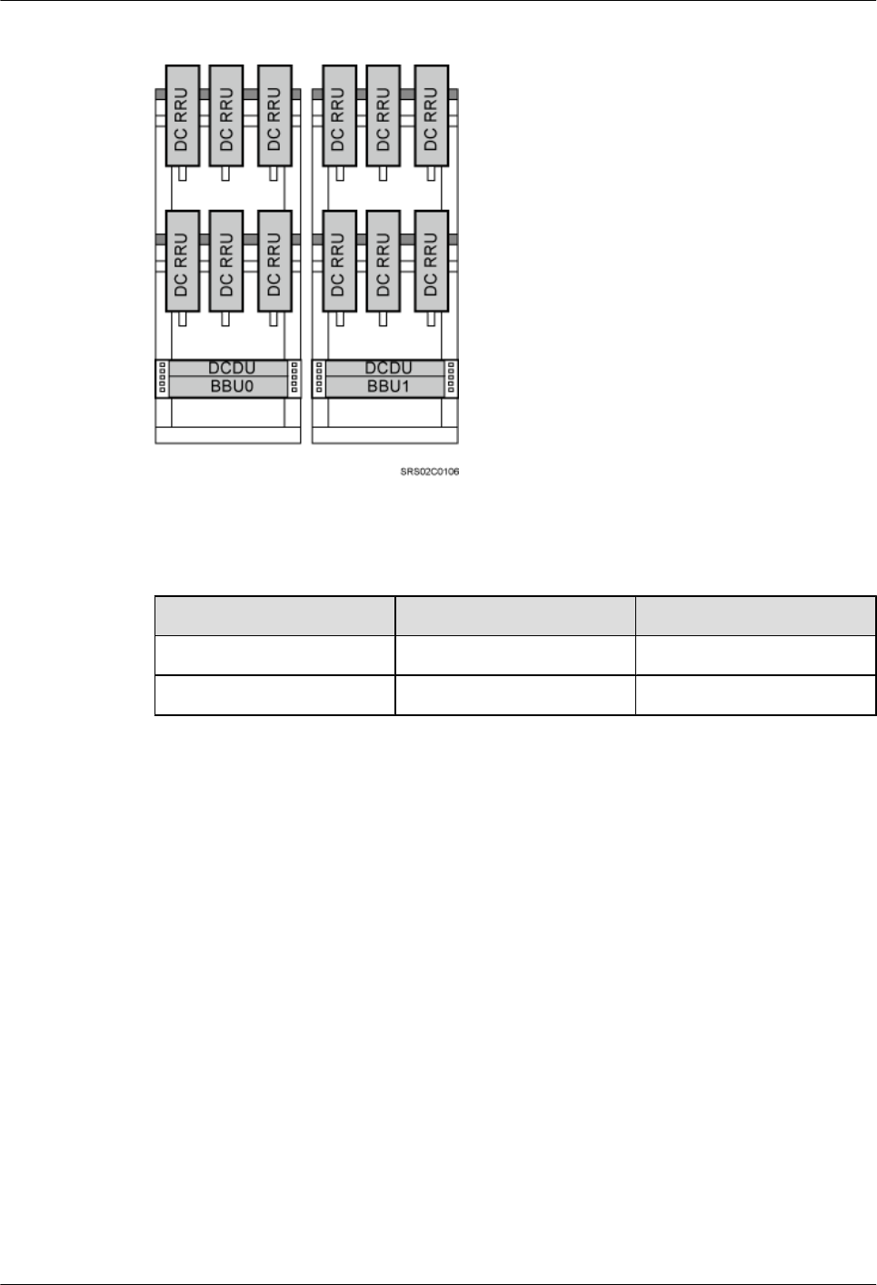
Figure 3-25 Triple-mode scenario (12 DC RRUs)
Table 3-24 12 DC RRUs (in GSM/UMTS/LTE mode)
Position GU+LTE GL+UMTS
ICR 1 6 RRU3908s 6 RRU3908s
ICR 2 6 RRU3201s 6 RRU3804s
RRUs Installed Independently (IFS06+DC RRUs)
In this scenario, a single IFS06 supports three or six DC RRUs. Figure 3-26 shows the scenario
where six DC RRUs are installed. When only three DC RRUs need to be installed, they are
installed at the lower layer.
DBS3900 (ICR)
Installation Guide 3 Information to Be Known Before the Installation
Issue 12 (2015-04-30) Huawei Proprietary and Confidential
Copyright © Huawei Technologies Co., Ltd.
31
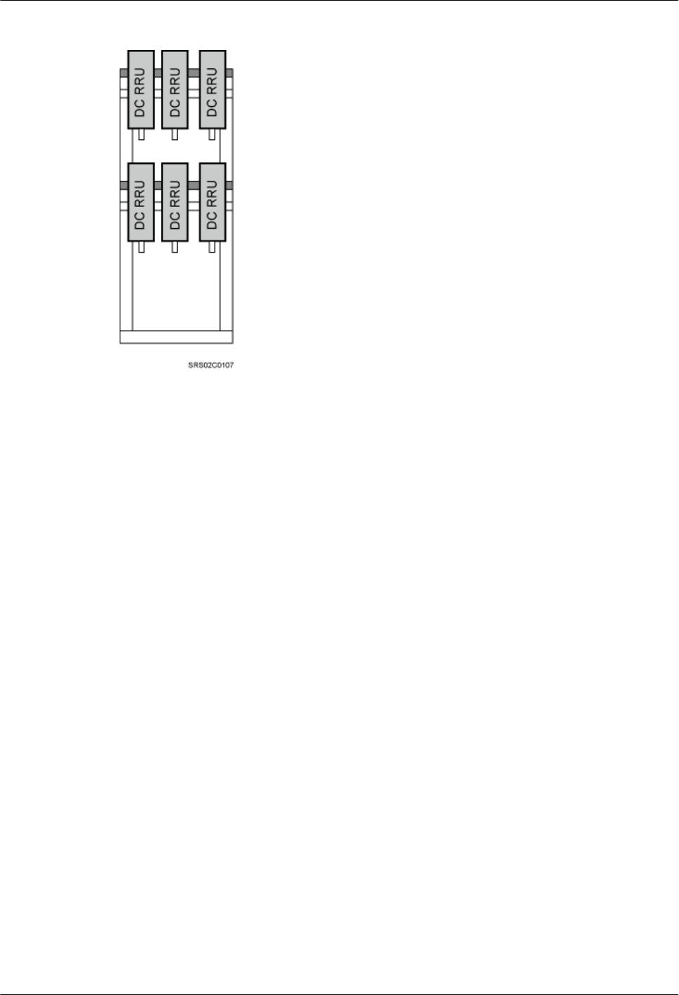
Figure 3-26 DC RRUs installed on the IFS06
Height-Unrestricted Scenarios (220 V AC)
This section describes the height-unrestricted scenarios with external 220 V AC power supply.
In these scenarios, RRUs can be installed together with an IMB03 on an IFS06 or independently
on an IFS06.
DC RRUs and IMB03 Installed Together (IFS06+IMB03+DC RRUs)
In single- or dual-mode scenarios, a single IFS06 supports a maximum of six DC RRUs, and a
single site supports a maximum of 12 DC RRUs. When only three DC RRUs need to be installed,
they are installed at the lower layer.
l1 IFS06+2 IMB03s+3 DC RRUs
DBS3900 (ICR)
Installation Guide 3 Information to Be Known Before the Installation
Issue 12 (2015-04-30) Huawei Proprietary and Confidential
Copyright © Huawei Technologies Co., Ltd.
32
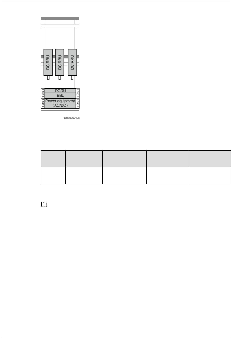
Figure 3-27 1 IFS06+2 IMB03s+3 DC RRUs
Table 3-25 3 DC RRUs
Position GSM UMTS LTE GSM+UMTS/
GSM+LTE
Lower
layer
3 RRU3008s 3 RRU3804s 3 RRU3201s 3 RRU3908s
NOTE
lRRU3008s are used as examples for RRUs in GSM mode.
lRRU3804s are used as examples for RRUs in UMTS mode.
lRRU3201s are used as examples for RRUs in LTE mode.
lRRU3908s are used as examples for RRUs in multiple modes.
l1 IFS06+2 IMB03s+6 DC RRUs
DBS3900 (ICR)
Installation Guide 3 Information to Be Known Before the Installation
Issue 12 (2015-04-30) Huawei Proprietary and Confidential
Copyright © Huawei Technologies Co., Ltd.
33
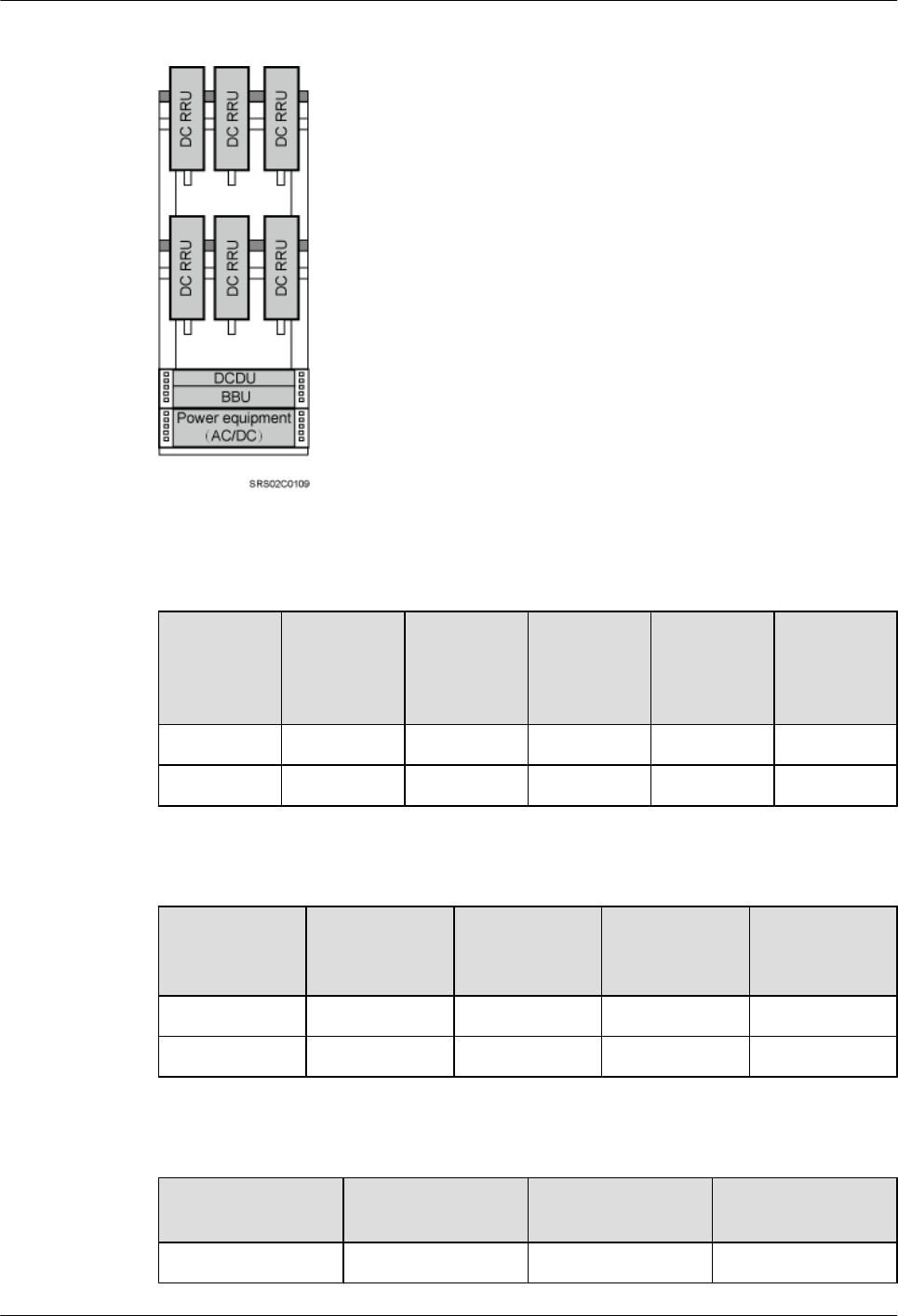
Figure 3-28 1 IFS06+2 IMB03s+6 DC RRUs
Table 3-26 6 DC RRUs (in GSM/UMTS mode)
Position GSM UMTS GSM
+UMTS
Co-Cabinet
of GSM
+UMTS
and UMTS
Co-Cabinet
of GSM
and UMTS
Upper layer 3 RRU3008s 3 RRU3804s 3 RRU3908s 3 RRU3908s 3 RRU3008s
Lower layer 3 RRU3008s 3 RRU3804s 3 RRU3908s 3 RRU3804s 3 RRU3804s
Table 3-27 6 DC RRUs (in GSM/LTE mode)
Position GSM LTE Co-Cabinet of
GSM+LTE
and LTE
Co-Cabinet of
GSM and LTE
Upper layer 3 RRU3008s 3 RRU3201s 3 RRU3908s 3 RRU3008s
Lower layer 3 RRU3008s 3 RRU3201s 3 RRU3201s 3 RRU3201s
Table 3-28 6 DC RRUs (in UMTS/LTE mode)
Position UMTS LTE Co-Cabinet of
UMTS and LTE
Upper layer 3 RRU3804s 3 RRU3201s 3 RRU3804s
DBS3900 (ICR)
Installation Guide 3 Information to Be Known Before the Installation
Issue 12 (2015-04-30) Huawei Proprietary and Confidential
Copyright © Huawei Technologies Co., Ltd.
34
Position UMTS LTE Co-Cabinet of
UMTS and LTE
Lower layer 3 RRU3804s 3 RRU3201s 3 RRU3201s
l2 IFS06s+4 IMB03s+12 DC RRUs
Figure 3-29 2 IFS06s+4 IMB03s+12 DC RRUs
Table 3-29 12 DC RRUs (in GSM/UMTS mode)
Position Co-Cabinet of GSM
+UMTS and UMTS
Co-Cabinet of GSM and
UMTS
ICR 1 6 RRU3908s 6 RRU3008s
ICR 2 6 RRU3804s 6 RRU3804s
Table 3-30 12 DC RRUs (in GSM/LTE mode)
Position Co-Cabinet of GSM
+UMTS and UMTS
Co-Cabinet of GSM and
UMTS
ICR 1 6 RRU3908s 6 RRU3008s
ICR 2 6 RRU3201s 6 RRU3201s
DBS3900 (ICR)
Installation Guide 3 Information to Be Known Before the Installation
Issue 12 (2015-04-30) Huawei Proprietary and Confidential
Copyright © Huawei Technologies Co., Ltd.
35
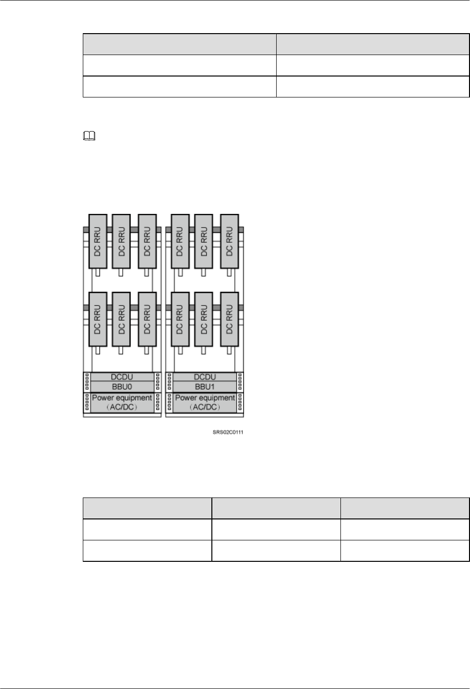
Table 3-31 12 DC RRUs (in UMTS/LTE mode)
Position Co-Cabinet of UMTS and LTE
ICR 1 6 RRU3804s
ICR 2 6 RRU3201s
NOTE
In triple-mode scenarios, when two ICRs are used, two BBUs are installed separately in two IMB03s. BBU
0 (primary BBU) is installed on the left IFS06, and BBU 1 (secondary BBU) is installed on the right IFS06,
as shown in Figure 3-30.
Figure 3-30 Triple-mode scenario (12 DC RRUs)
Table 3-32 12 DC RRUs (in GSM/UMTS/LTE mode)
Position GU+LTE GL+UMTS
ICR 1 6 RRU3908s 6 RRU3908s
ICR 2 6 RRU3201s 6 RRU3804s
RRUs Installed Independently (IFS06+RRUs)
lIFS06+DC RRUs
In this scenario, a single IFS06 supports three or six DC RRUs. Figure 3-31 shows the scenario
where six DC RRUs are installed. When only three DC RRUs need to be installed, they are
installed at the lower layer.
DBS3900 (ICR)
Installation Guide 3 Information to Be Known Before the Installation
Issue 12 (2015-04-30) Huawei Proprietary and Confidential
Copyright © Huawei Technologies Co., Ltd.
36
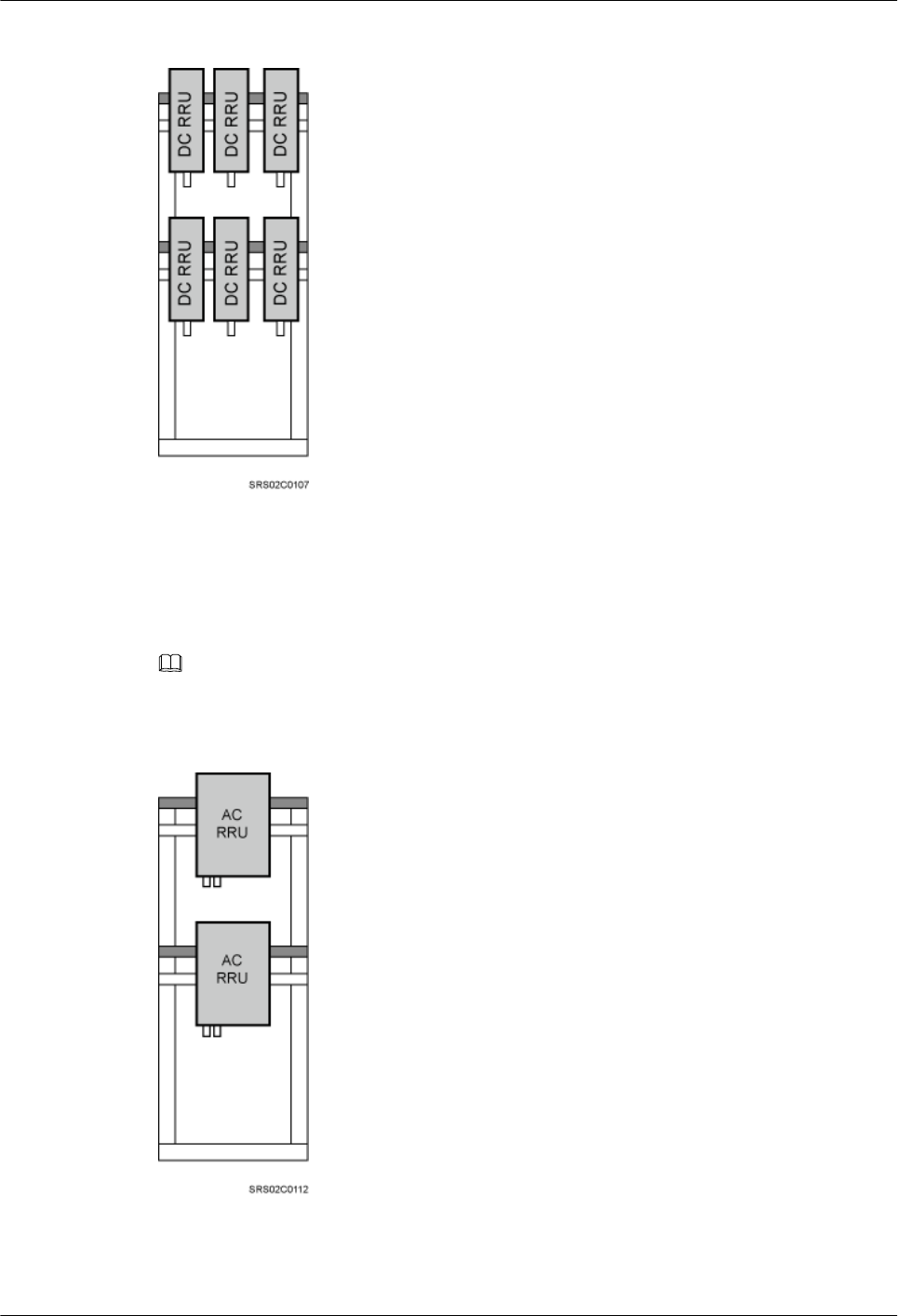
Figure 3-31 DC RRUs installed on the IFS06
lIFS06+AC RRUs
In this scenario, a single IFS06 supports a maximum two AC RRUs, as shown in Figure 3-32.
NOTE
This document uses AC RRU3908s as examples.
Figure 3-32 AC RRUs installed on the IFS06
DBS3900 (ICR)
Installation Guide 3 Information to Be Known Before the Installation
Issue 12 (2015-04-30) Huawei Proprietary and Confidential
Copyright © Huawei Technologies Co., Ltd.
37
Height-Unrestricted Scenarios (+24 V DC)
This section describes the height-unrestricted scenarios with external +24 V DC power supply.
In these scenarios, DC RRUs can be installed together with an IMB03 on an IFS06 or
independently on an IFS06.
DC RRUs and IMB03 Installed Together (IFS06+IMB03+DC RRUs)
In single- or dual-mode scenarios, a single IFS06 supports a maximum of six DC RRUs, and a
single site supports a maximum of 12 DC RRUs. When only three DC RRUs need to be installed,
they are installed at the lower layer.
l1 IFS06+2 IMB03s+3 DC RRUs
Figure 3-33 1 IFS06+2 IMB03s+3 DC RRUs
Table 3-33 3 DC RRUs
Position GSM UMTS LTE GSM+UMTS/
GSM+LTE
Lower
layer
3 RRU3008s 3 RRU3804s 3 RRU3201s 3 RRU3908s
NOTE
lRRU3008s are used as examples for RRUs in GSM mode.
lRRU3804s are used as examples for RRUs in UMTS mode.
lRRU3201s are used as examples for RRUs in LTE mode.
lRRU3908s are used as examples for RRUs in multiple modes.
DBS3900 (ICR)
Installation Guide 3 Information to Be Known Before the Installation
Issue 12 (2015-04-30) Huawei Proprietary and Confidential
Copyright © Huawei Technologies Co., Ltd.
38
l1 IFS06+2 IMB03s+6 DC RRUs
Figure 3-34 1 IFS06+2 IMB03s+6 DC RRUs
Table 3-34 6 DC RRUs (in GSM/UMTS mode)
Position GSM UMTS GSM
+UMTS
Co-Cabinet
of GSM
+UMTS
and UMTS
Co-Cabinet
of GSM
and UMTS
Upper layer 3 RRU3008s 3 RRU3804s 3 RRU3908s 3 RRU3908s 3 RRU3008s
Lower layer 3 RRU3008s 3 RRU3804s 3 RRU3908s 3 RRU3804s 3 RRU3804s
Table 3-35 6 DC RRUs (in GSM/LTE mode)
Position GSM LTE Co-Cabinet of
GSM+LTE
and LTE
Co-Cabinet of
GSM and LTE
Upper layer 3 RRU3008s 3 RRU3201s 3 RRU3908s 3 RRU3008s
Lower layer 3 RRU3008s 3 RRU3201s 3 RRU3201s 3 RRU3201s
DBS3900 (ICR)
Installation Guide 3 Information to Be Known Before the Installation
Issue 12 (2015-04-30) Huawei Proprietary and Confidential
Copyright © Huawei Technologies Co., Ltd.
39
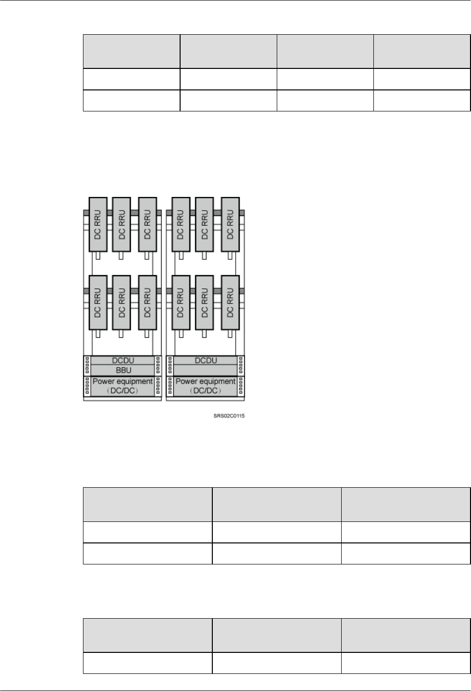
Table 3-36 6 DC RRUs (in UMTS/LTE mode)
Position UMTS LTE Co-Cabinet of
UMTS and LTE
Upper layer 3 RRU3804s 3 RRU3201s 3 RRU3804s
Lower layer 3 RRU3804s 3 RRU3201s 3 RRU3201s
l2 IFS06s+4 IMB03s+12 DC RRUs
Figure 3-35 2 IFS06s+4 IMB03s+12 DC RRUs
Table 3-37 12 DC RRUs (in GSM/UMTS mode)
Position Co-Cabinet of GSM
+UMTS and UMTS
Co-Cabinet of GSM and
UMTS
ICR 1 6 RRU3908s 6 RRU3008s
ICR 2 6 RRU3804s 6 RRU3804s
Table 3-38 12 DC RRUs (in GSM/LTE mode)
Position Co-Cabinet of GSM
+UMTS and UMTS
Co-Cabinet of GSM and
UMTS
ICR 1 6 RRU3908s 6 RRU3008s
DBS3900 (ICR)
Installation Guide 3 Information to Be Known Before the Installation
Issue 12 (2015-04-30) Huawei Proprietary and Confidential
Copyright © Huawei Technologies Co., Ltd.
40
Position Co-Cabinet of GSM
+UMTS and UMTS
Co-Cabinet of GSM and
UMTS
ICR 2 6 RRU3201s 6 RRU3201s
Table 3-39 12 DC RRUs (in UMTS/LTE mode)
Position Co-Cabinet of UMTS and LTE
ICR 1 6 RRU3804s
ICR 2 6 RRU3201s
NOTE
In triple-mode scenarios, when two ICRs are used, two BBUs are installed separately in two IMB03s. BBU
0 (primary BBU) is installed on the left IFS06, and BBU 1 (secondary BBU) is installed on the right IFS06,
as shown in Figure 3-36.
Figure 3-36 Triple-mode scenario
Table 3-40 12 DC RRUs (in GSM/UMTS/LTE mode)
Position GU+LTE GL+UMTS
ICR 1 6 RRU3908s 6 RRU3908s
ICR 2 6 RRU3201s 6 RRU3804s
DBS3900 (ICR)
Installation Guide 3 Information to Be Known Before the Installation
Issue 12 (2015-04-30) Huawei Proprietary and Confidential
Copyright © Huawei Technologies Co., Ltd.
41
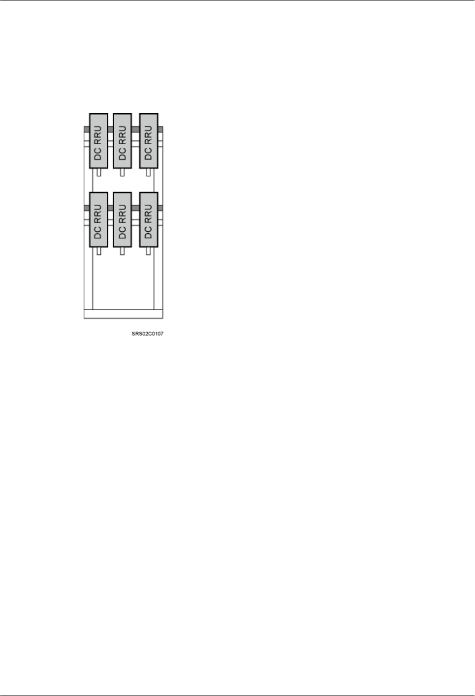
RRUs Installed Independently (IFS06+DC RRUs)
In this scenario, a single IFS06 supports three or six DC RRUs. Figure 3-37 shows the scenario
where six DC RRUs are installed. When only three DC RRUs need to be installed, they are
installed at the lower layer.
Figure 3-37 DC RRUs installed on the IFS06
3.3 Requirements for Dimensions and Clearances
This section describes the requirements for dimensions and clearances of devices to be installed.
Dimensions
Figure 3-38 shows the dimensions of an IFS06.
DBS3900 (ICR)
Installation Guide 3 Information to Be Known Before the Installation
Issue 12 (2015-04-30) Huawei Proprietary and Confidential
Copyright © Huawei Technologies Co., Ltd.
42
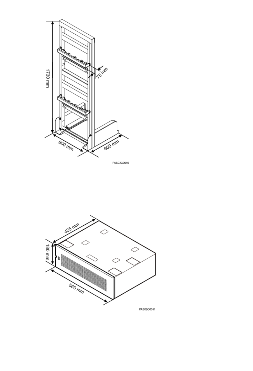
Figure 3-38 Dimensions of an IFS06
Figure 3-39 shows the dimensions of an IMB03.
Figure 3-39 Dimensions of an IMB03
Recommended Clearances
Figure 3-40 shows the recommended clearances for installing DC RRUs.
DBS3900 (ICR)
Installation Guide 3 Information to Be Known Before the Installation
Issue 12 (2015-04-30) Huawei Proprietary and Confidential
Copyright © Huawei Technologies Co., Ltd.
43
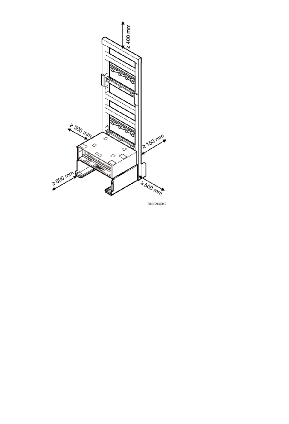
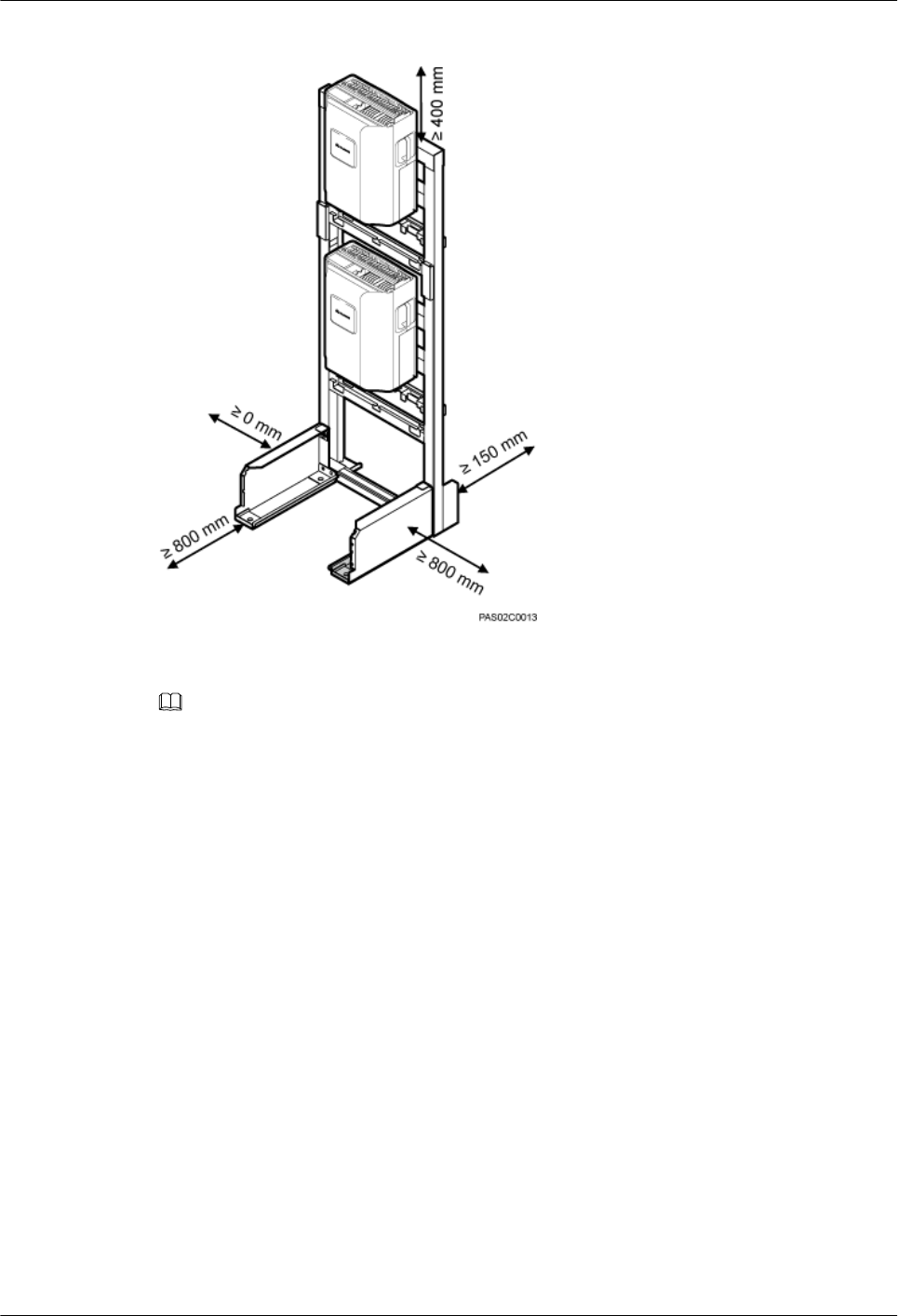
Figure 3-41 Recommended clearances (for AC RRUs)
NOTE
When an IFS06 needs to provide the recommended clearances for used for AC RRUs, it can be installed
with its left side close to a wall.
Minimum Clearances
Figure 3-42 shows the minimum clearances for installing DC RRUs in height-unrestricted
scenarios.
DBS3900 (ICR)
Installation Guide 3 Information to Be Known Before the Installation
Issue 12 (2015-04-30) Huawei Proprietary and Confidential
Copyright © Huawei Technologies Co., Ltd.
45
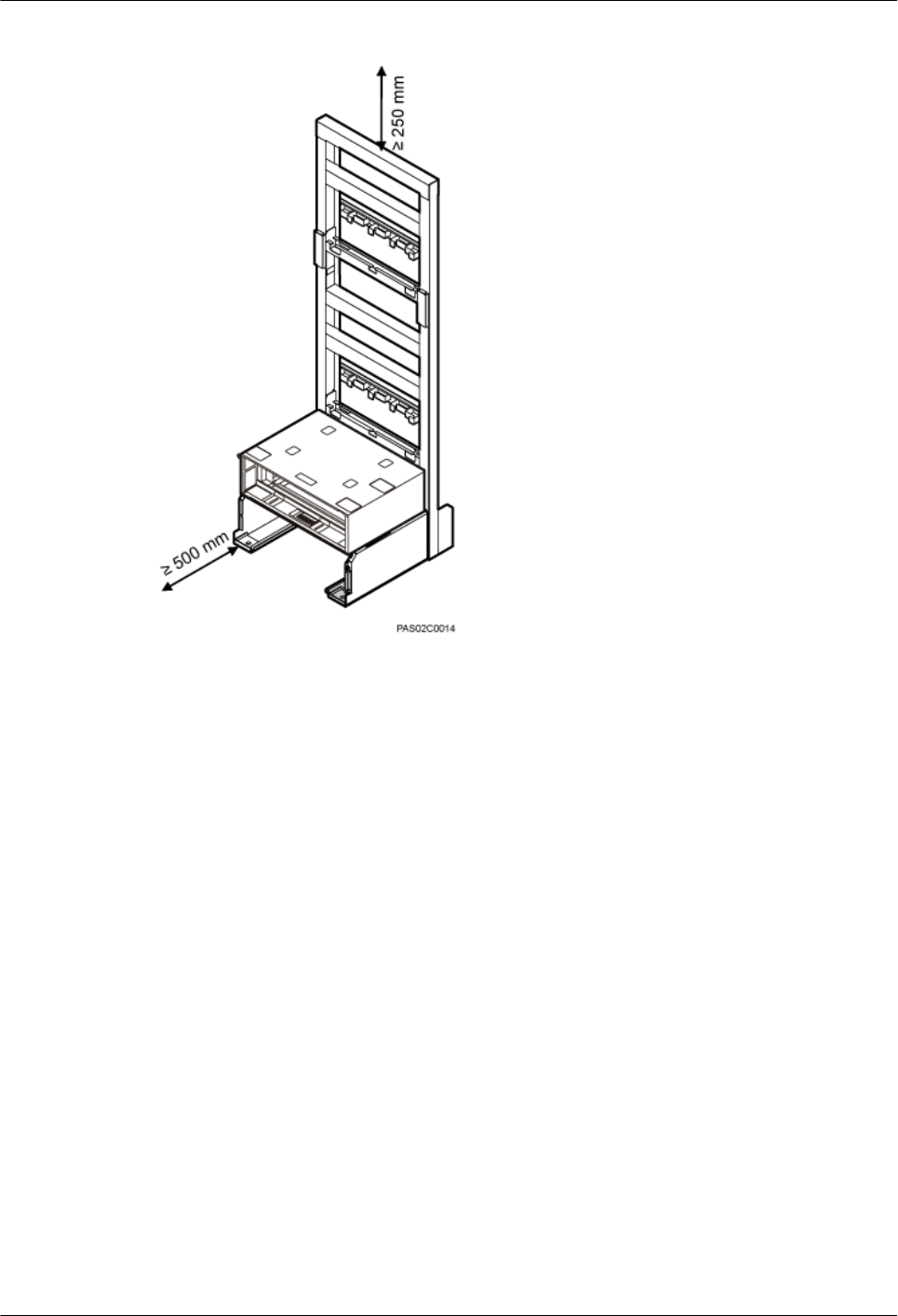
Figure 3-42 Minimum clearances for installing DC RRUs in height-unrestricted scenarios
Figure 3-43 shows the minimum clearances for installing DC RRUs in height-restricted
scenarios.
DBS3900 (ICR)
Installation Guide 3 Information to Be Known Before the Installation
Issue 12 (2015-04-30) Huawei Proprietary and Confidential
Copyright © Huawei Technologies Co., Ltd.
46
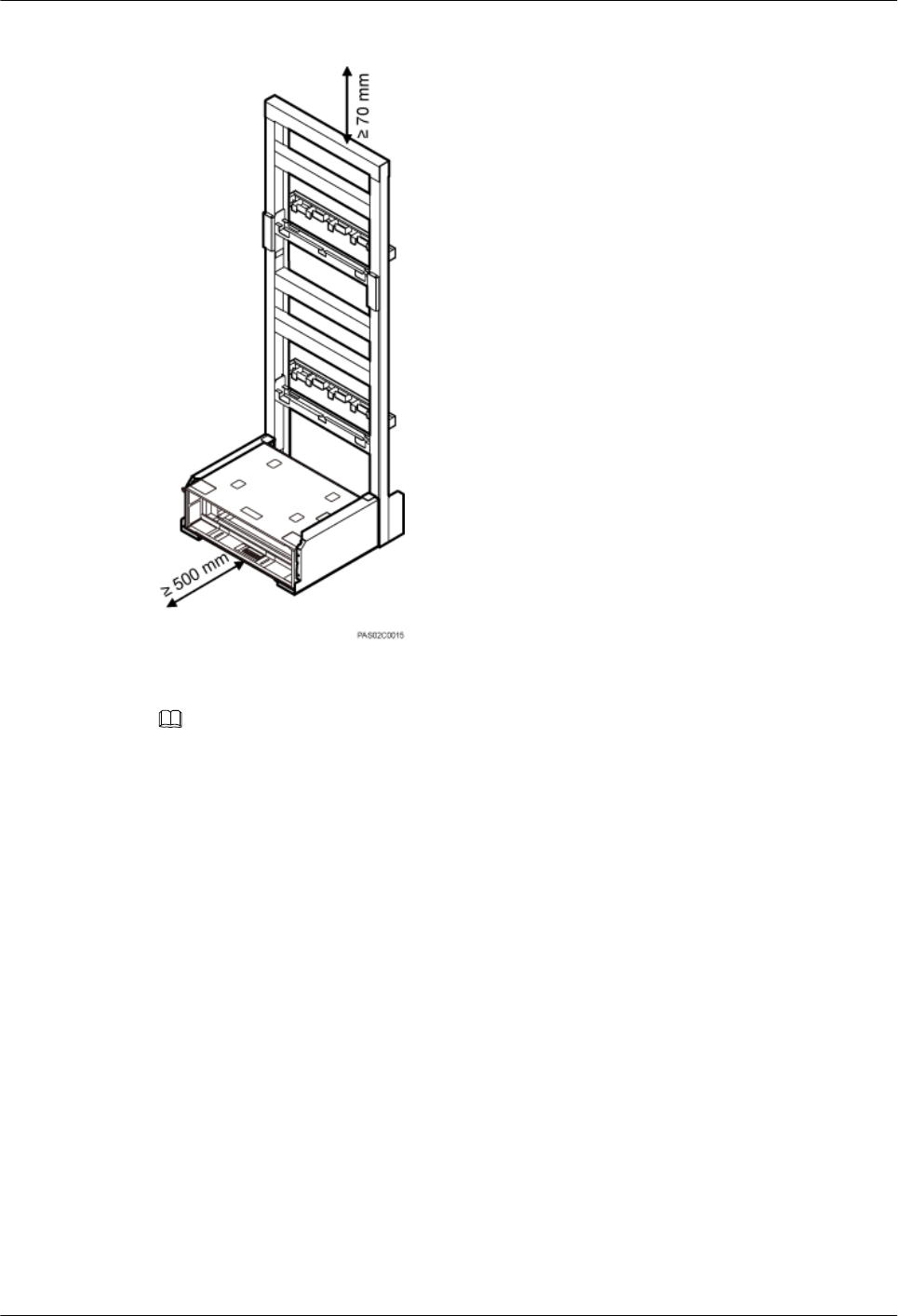
Figure 3-43 Minimum clearances for installing DC RRUs in height-restricted scenarios
NOTE
When an IFS06 needs to provide the minimum clearances for DC RRUs, it can be installed with its rear
and both sides close to walls.
Figure 3-44 shows the minimum clearances for installing AC RRUs.
DBS3900 (ICR)
Installation Guide 3 Information to Be Known Before the Installation
Issue 12 (2015-04-30) Huawei Proprietary and Confidential
Copyright © Huawei Technologies Co., Ltd.
47
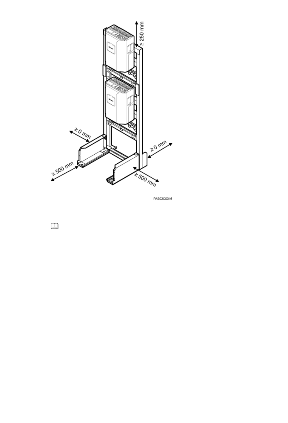
Figure 3-44 Minimum clearances (for AC RRUs)
NOTE
When an IFS06 needs to provide the minimum clearances for AC RRUs, it can be installed with its rear
and both sides close to walls.
Clearance Requirements of Combined Cabinets
Figure 3-45 shows the clearance requirements of combined cabinets.
DBS3900 (ICR)
Installation Guide 3 Information to Be Known Before the Installation
Issue 12 (2015-04-30) Huawei Proprietary and Confidential
Copyright © Huawei Technologies Co., Ltd.
48
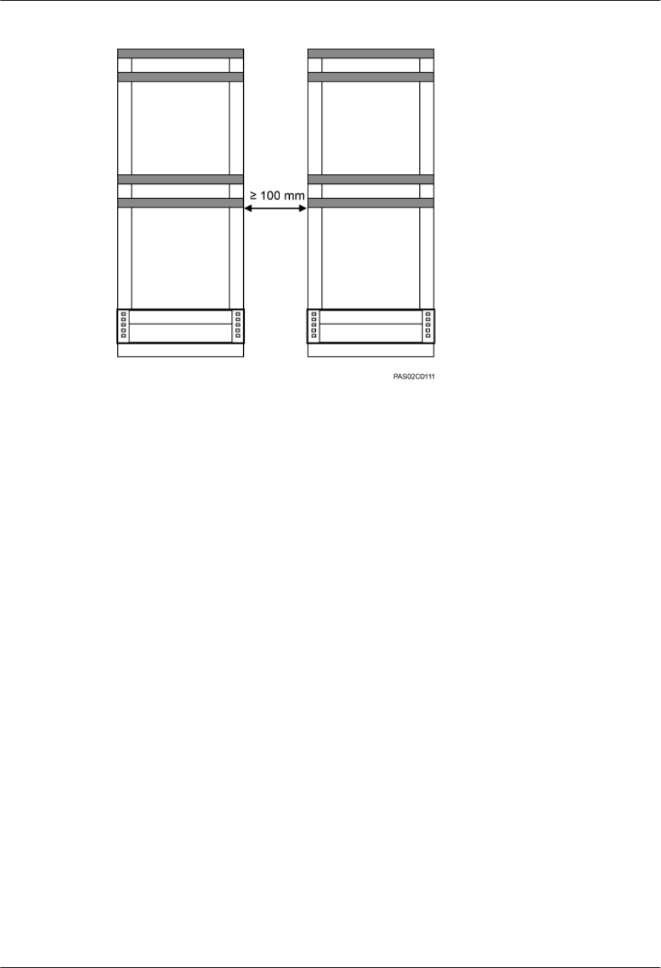
Figure 3-45 Clearance requirements of combined cabinets
DBS3900 (ICR)
Installation Guide 3 Information to Be Known Before the Installation
Issue 12 (2015-04-30) Huawei Proprietary and Confidential
Copyright © Huawei Technologies Co., Ltd.
49
4 Unpacking the Equipment
This chapter describes how to unpack and check the delivered equipment to ensure that all the
materials are included and intact.
Context
NOTE
When transporting, moving, or installing the equipment, components, or parts, you must:
lPrevent them from colliding with doors, walls, shelves, or other objects.
lWear clean gloves, and avoid touching the equipment, components, or parts with bare hands, sweat-
soaked gloves, or dirty gloves.
NOTICE
lAfter a cabinet or an BBU is unpacked, it must be powered on within 7 days.
lAfter an RRU is unpacked, it must be powered on within 24 hours.
Procedure
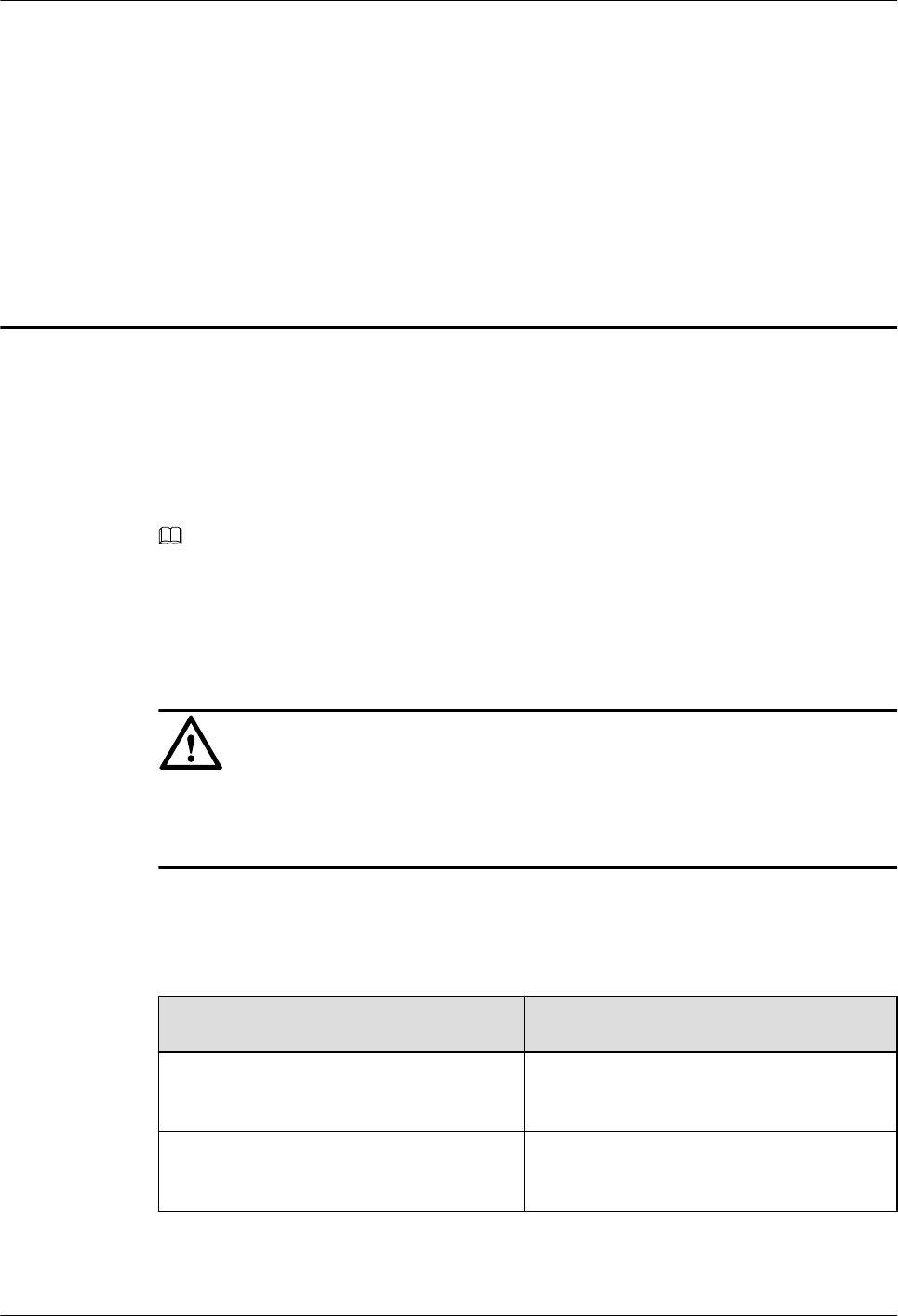
Step 1 Check the total number of articles in each case according to the packing list.
If ... Then ...
The total number tallies with the packing
list
Go to Step 2.
The total number does not tally with the
packing list
Find out the cause and report any missing
articles to the local Huawei office.
Step 2 Check the exterior of the packing case.
DBS3900 (ICR)
Installation Guide 4 Unpacking the Equipment
Issue 12 (2015-04-30) Huawei Proprietary and Confidential
Copyright © Huawei Technologies Co., Ltd.
50
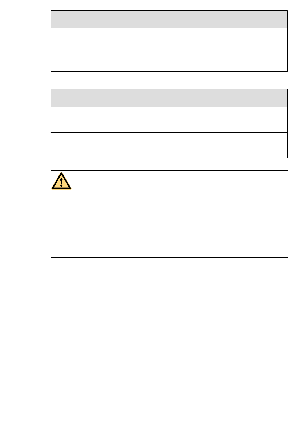
If ... Then ...
The outer packing is intact Go to Step 3.
The outer packing is severely damaged or
soaked
Find out the cause and report it to the local
Huawei office.
Step 3 Check the type and quantity of the equipment in the cases according to the packing list.
If ... Then ...
Types and quantity of the article tally with
those on the packing list
Sign the Packing List with the customer.
Either shipment shortage, wrong shipment
or damaged articles.
Report to the local Huawei office.
CAUTION
lTo protect the equipment and prevent damage to the equipment, you are advised to keep the
unpacked equipment and packing materials indoors, take photos of the stocking environment,
packing case or carton, packing materials, and any rusted or eroded equipment, and then file
the photos.
lVerify that the insulation layers of all RRU cables are intact. If the insulation layers are
damaged or broken, water will penetrate into the cables, which may cause damages to RRUs
or human injury.
----End
DBS3900 (ICR)
Installation Guide 4 Unpacking the Equipment
Issue 12 (2015-04-30) Huawei Proprietary and Confidential
Copyright © Huawei Technologies Co., Ltd.
51
5 Obtaining the ESN
This chapter describes how to obtain the Electronic Serial Number (ESN). The ESN is a unique
identifier of a Network Element (NE). Record the ESN for later commissioning of the base
station before installation.
Procedure
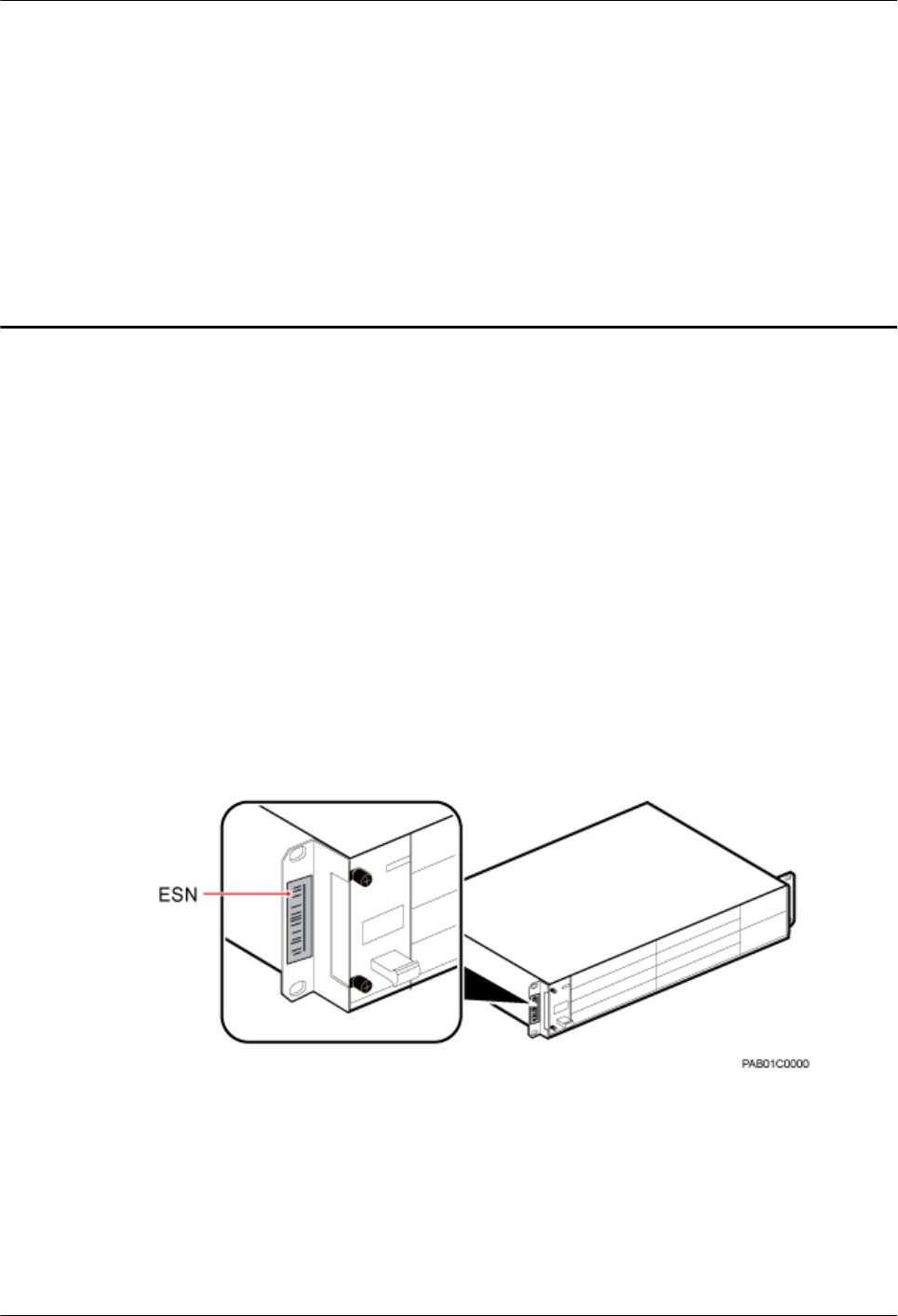
Step 1 Record the ESN on the BBU.
lIf there is not a label on the FAN unit of the BBU, you must record the ESN and site
information that is printed on a mounting ear of the BBU. Figure 5-1 shows the position of
the ESN.
lIf there is a label on the FAN unit of the BBU, the ESN is printed on the label and a mounting
ear of the BBU. In this case, you must take the label and record the site information on the
side labeled Site, as shown in Figure 5-2.
Figure 5-1 Obtaining the ESN (1)
DBS3900 (ICR)
Installation Guide 5 Obtaining the ESN
Issue 12 (2015-04-30) Huawei Proprietary and Confidential
Copyright © Huawei Technologies Co., Ltd.
52
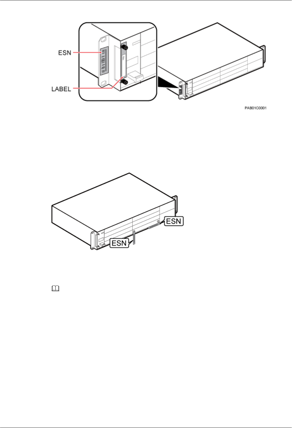
Figure 5-2 Obtaining the ESN (2)
Step 2 Record the ESN on the WMPT.
Figure 5-3 shows the position of the ESN.
Figure 5-3 Obtaining the ESN
Step 3 Report the ESN to the engineer for the commissioning of the base station.
NOTE
If multiple BBUs need to be configured on site, record the ESN for each BBU and report them to the
engineer responsible for base station commissioning.
----End
DBS3900 (ICR)
Installation Guide 5 Obtaining the ESN
Issue 12 (2015-04-30) Huawei Proprietary and Confidential
Copyright © Huawei Technologies Co., Ltd.
53

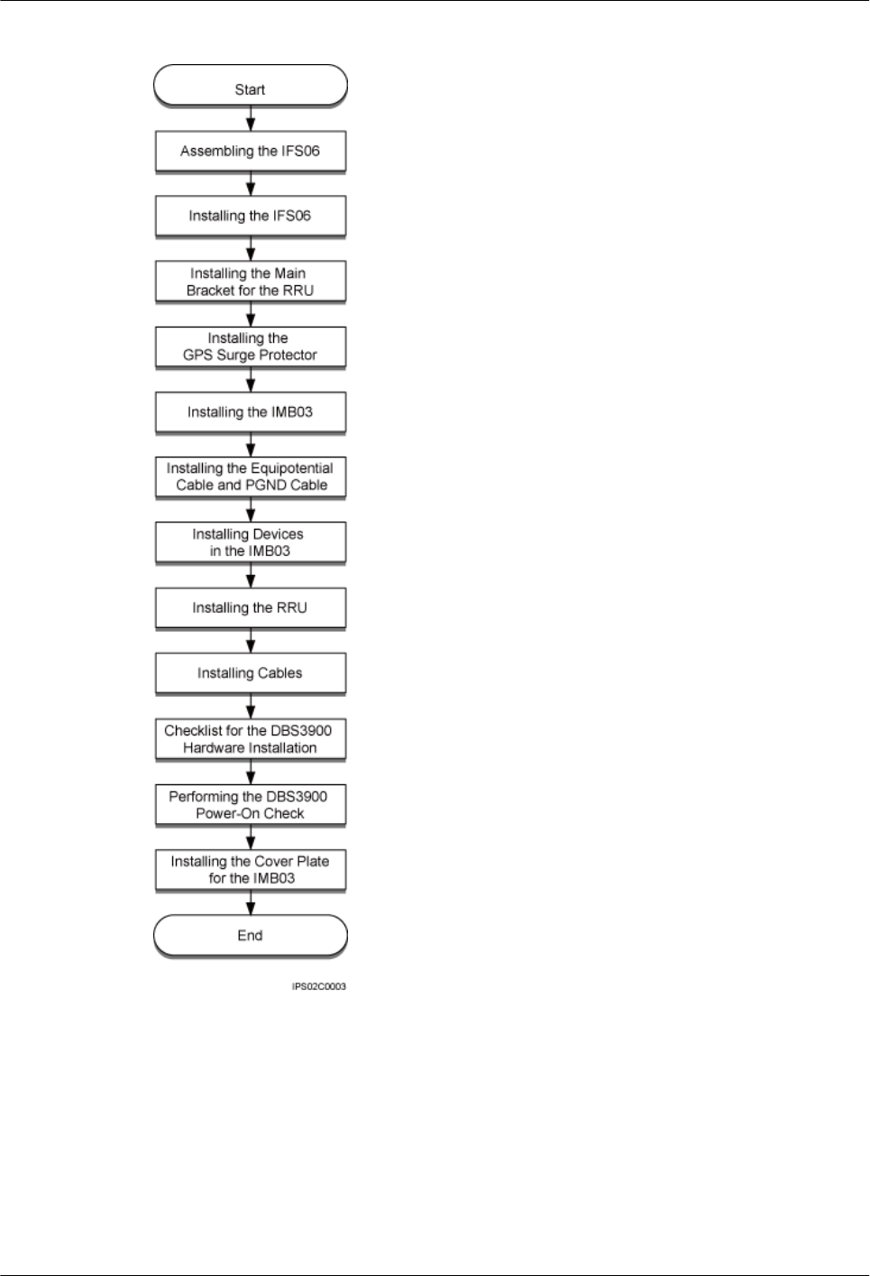
Figure 6-1 Installation process
DBS3900 (ICR)
Installation Guide 6 Installation Process
Issue 12 (2015-04-30) Huawei Proprietary and Confidential
Copyright © Huawei Technologies Co., Ltd.
55
7 Assembling the IFS06
This chapter describes the procedure for assembling an IFS06.
Procedure
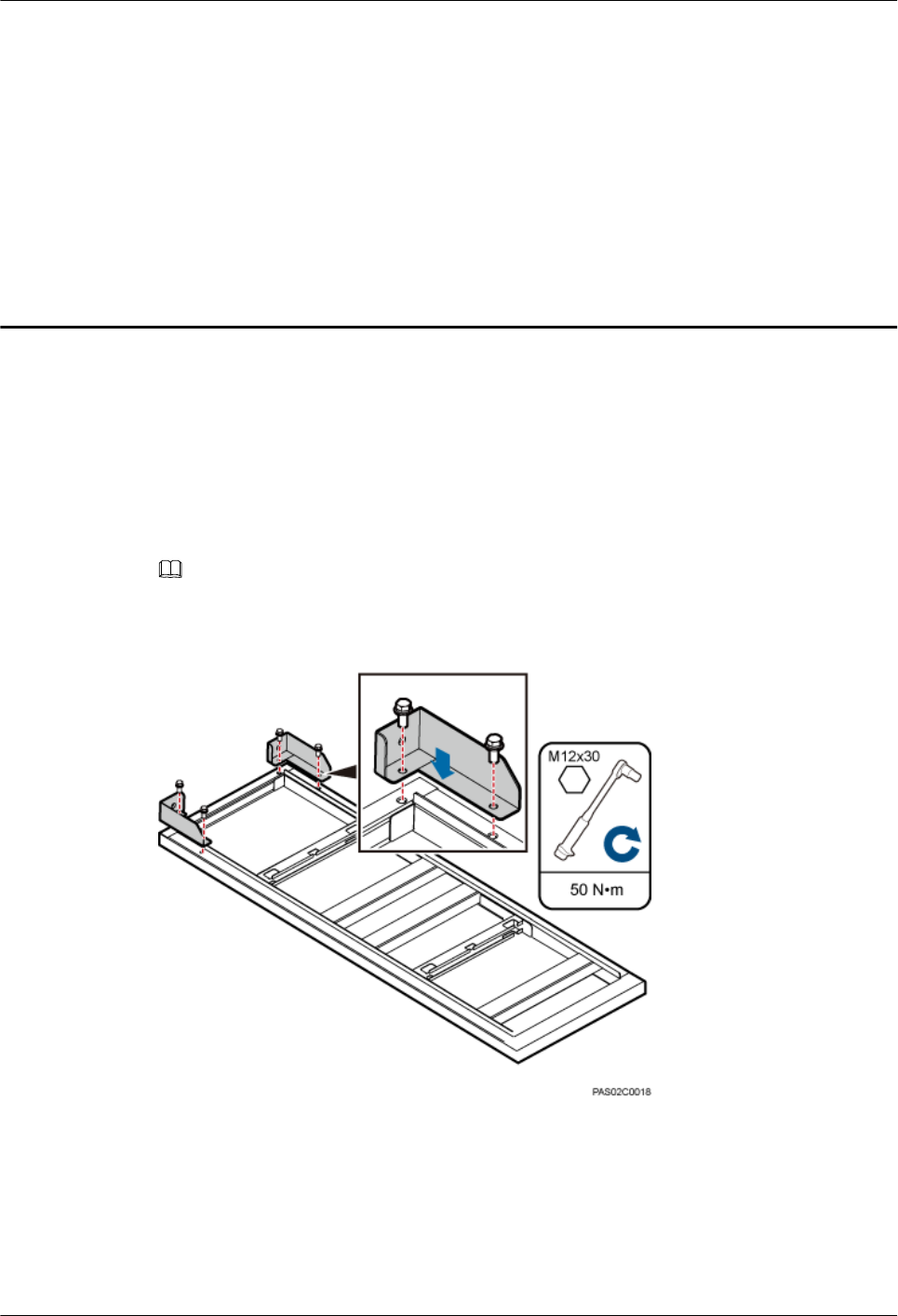
Step 1 Use four M12×30 bolt assemblies to secure rear feet to the main frame, with a torque of 50 N·m
(442.54 lbf·in.), as shown in Figure 7-1.
NOTE
Place a foam pad or cardboard under the IFS06 to prevent any damage to the paint.
Figure 7-1 Installing the rear feet
Step 2 Turn over the IFS06 and use six M12×30 bolt assemblies to secure front feet to the main frame,
with a torque of 50 N·m (442.54 lbf·in.), as shown in Figure 7-2.
DBS3900 (ICR)
Installation Guide 7 Assembling the IFS06
Issue 12 (2015-04-30) Huawei Proprietary and Confidential
Copyright © Huawei Technologies Co., Ltd.
56
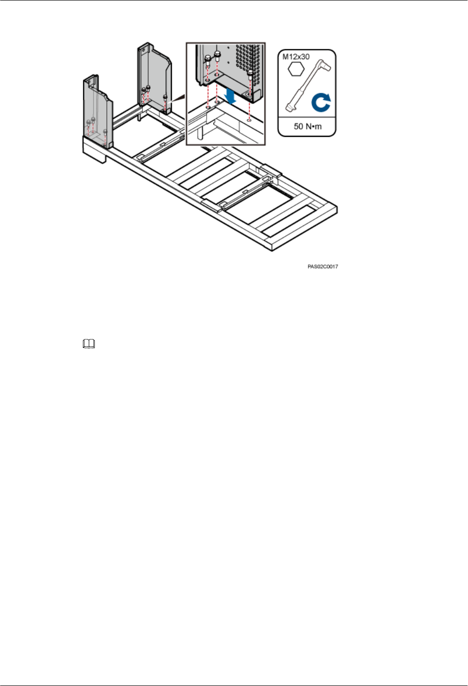
Figure 7-2 Installing the front feet
Step 3 Optional: In height-restricted scenarios, move the adjustable beams from the positions marked
2 m (6.56 ft) to the positions marked 1.8 m (5.91 ft), as shown in Figure 7-3.
NOTE
The adjustable beams do not need to be moved in height-unrestricted scenarios.
DBS3900 (ICR)
Installation Guide 7 Assembling the IFS06
Issue 12 (2015-04-30) Huawei Proprietary and Confidential
Copyright © Huawei Technologies Co., Ltd.
57
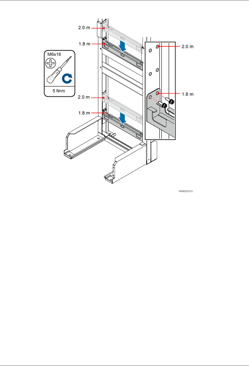
Figure 7-3 Moving the adjustable beam
Step 4 Insert the tabs of the cable trays into the slots on the columns of the IFS06, as shown in Figure
7-4.
DBS3900 (ICR)
Installation Guide 7 Assembling the IFS06
Issue 12 (2015-04-30) Huawei Proprietary and Confidential
Copyright © Huawei Technologies Co., Ltd.
58
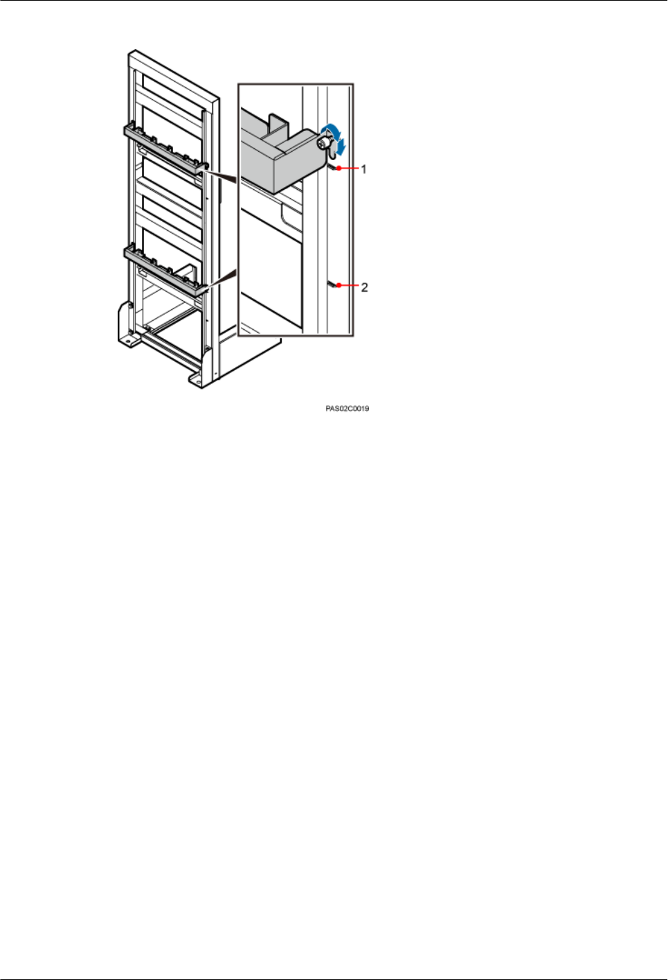
Figure 7-4 Installing cable trays
(1) Slots for installing cable trays in height-unrestricted
scenarios
(2) Slots for installing cable trays in height-restricted
scenarios
Step 5 Secure the attachment plates for the GPS surge protector onto the upper adjustable beam, as
shown in Figure 7-5.
DBS3900 (ICR)
Installation Guide 7 Assembling the IFS06
Issue 12 (2015-04-30) Huawei Proprietary and Confidential
Copyright © Huawei Technologies Co., Ltd.
59
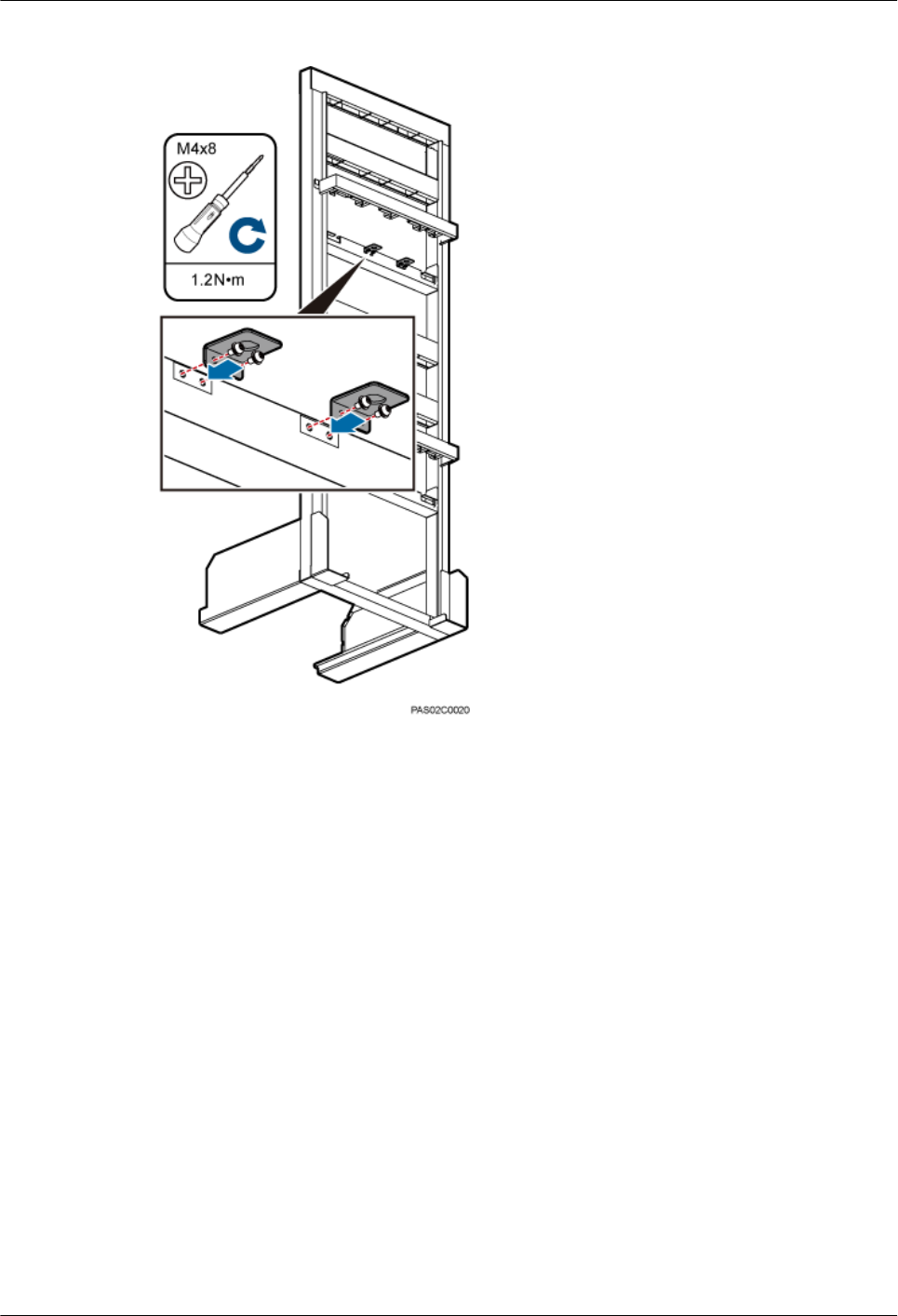
Figure 7-5 Installing the attachment plates for the GPS surge protector
----End
DBS3900 (ICR)
Installation Guide 7 Assembling the IFS06
Issue 12 (2015-04-30) Huawei Proprietary and Confidential
Copyright © Huawei Technologies Co., Ltd.
60

8 Installing the IFS06
About This Chapter
This chapter describes the procedures for installing the IFS06 on the concrete floor and ESD
floor.
8.1 Installing the IFS06 on the Concrete Floor
This section describes the procedure for installing the IFS06 on the concrete floor.
8.2 Installing the IFS06 on the ESD Floor
This section describes the procedure for installing the IFS06 on the ESD floor.
DBS3900 (ICR)
Installation Guide 8 Installing the IFS06
Issue 12 (2015-04-30) Huawei Proprietary and Confidential
Copyright © Huawei Technologies Co., Ltd.
61
8.1 Installing the IFS06 on the Concrete Floor
This section describes the procedure for installing the IFS06 on the concrete floor.
Procedure
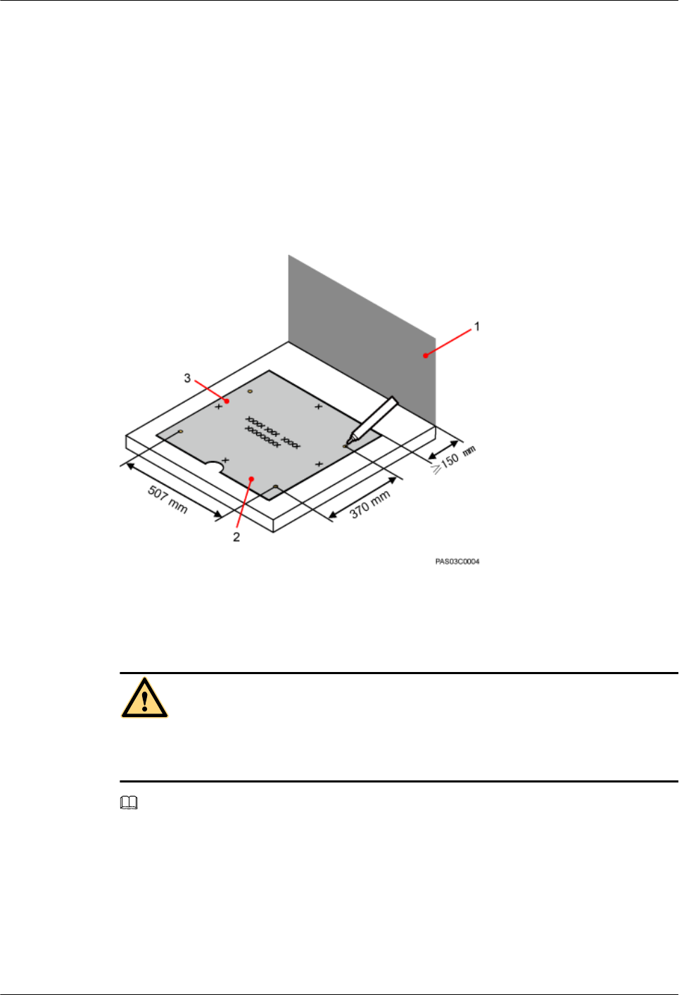
Step 1 Place the marking-off template on the floor. Then use a marker to mark four anchor points, as
shown in Figure 8-1.
Figure 8-1 Marking anchor points
(1) Wall (2) Front (3) Left
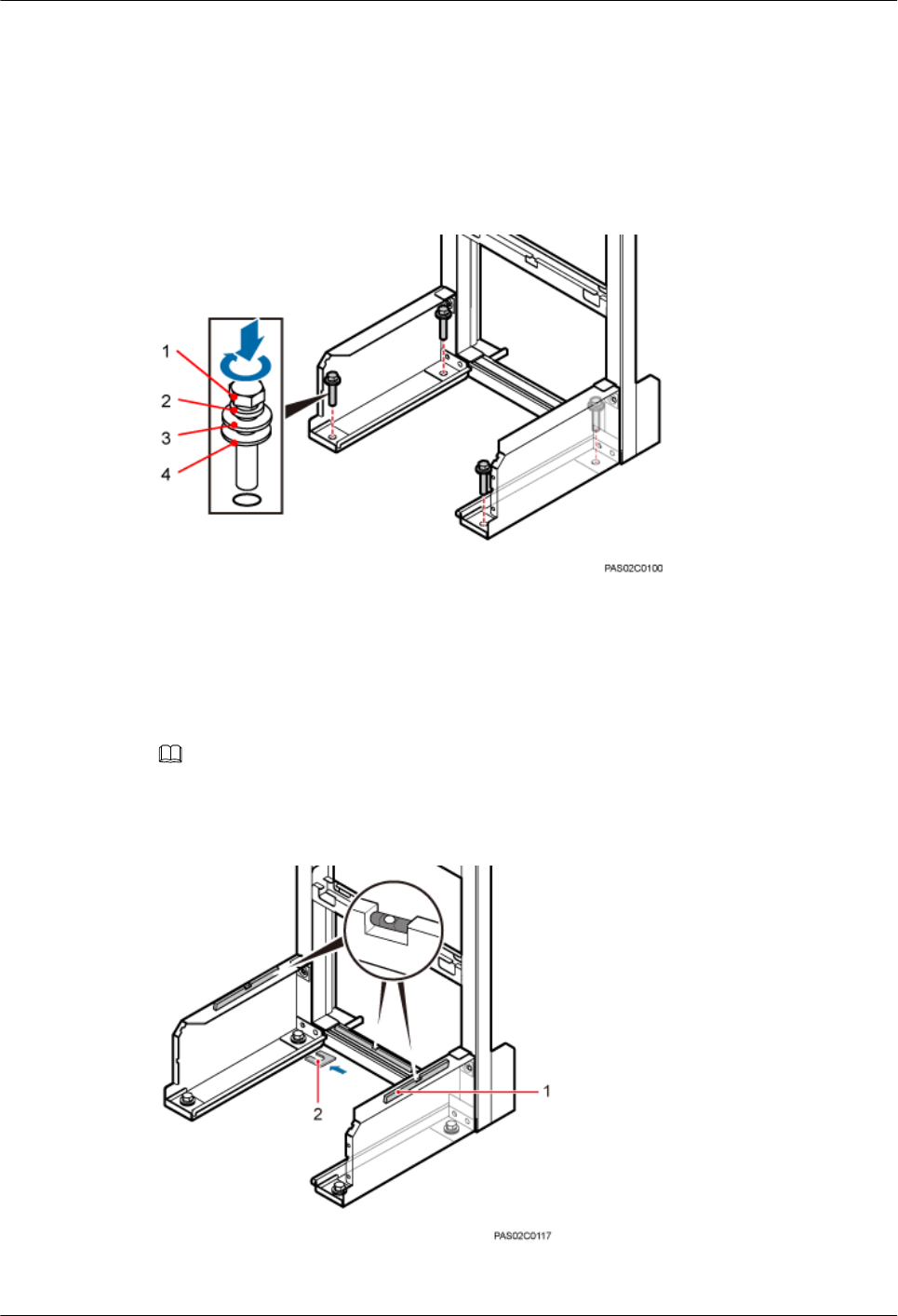
Step 2 Drill holes at the anchor points and install expansion bolt assemblies in the holes, as shown in
the following figure.
CAUTION
Take proper safety measures to protect your eyes and respiratory tract against the dust before
drilling holes.
NOTE
Generally, the concrete floor is solid and smooth. Therefore, you can use the center punch to help locate
the drill bit. If the conditions of the floor allow direct drilling, skip this step.
DBS3900 (ICR)
Installation Guide 8 Installing the IFS06
Issue 12 (2015-04-30) Huawei Proprietary and Confidential
Copyright © Huawei Technologies Co., Ltd.
62
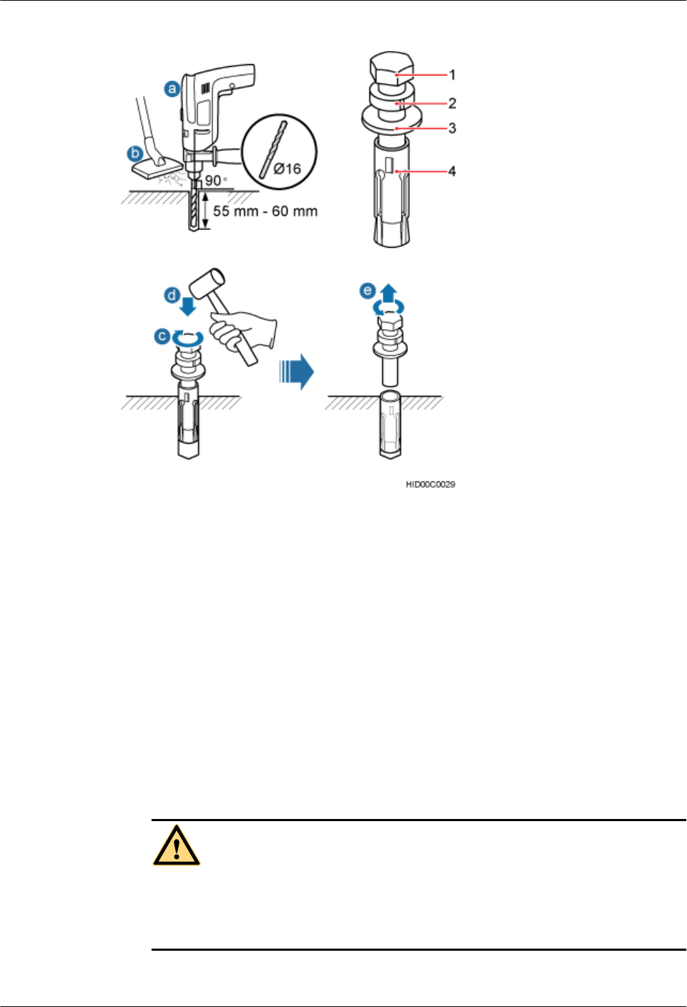
Figure 8-2 Drilling a hole and inserting an expansion bolt assembly
(1) M12x60 bolts (2) Spring washer (3) Flat washer (4) Expansion tube
1. Use a hammer drill with a Φ16 drill bit to drill holes with a depth ranging from 55 mm
(2.05 in.) to 60 mm (2.36 in.).
2. Use a vacuum cleaner to clear the dust out from inside and around the holes, and measure
the distances between holes. If any of the hole is beyond the acceptable range, mark a new
anchor point and drill a new hole.
3. Tighten an expansion bolt slightly and place it vertically into each hole.
4. Hit the expansion bolt with a rubber mallet until the expansion tube completely enters the
hole.
5. Turning the M12x60 bolt, spring washer, and flat washer counterclockwise, and remove
them in sequence.
CAUTION
After dismantling the expansion bolt assembly, ensure that the top of the expansion tube
is level with the concrete floor. Otherwise, the cabinet cannot be installed on the concrete
floor evenly and securely.
Step 3 Place the IFS06, as shown in Figure 8-3.
DBS3900 (ICR)
Installation Guide 8 Installing the IFS06
Issue 12 (2015-04-30) Huawei Proprietary and Confidential
Copyright © Huawei Technologies Co., Ltd.
63
1. Place the IFS06, with the mounting holes on the IFS06 aligned with the anchor points on
the floor.
2. Lead each bolt through the spring washer, flat washer, and insulation washer in sequence.
Then install the bolts in the mounting holes on the IFS06.
3. Partially tighten the bolts into the expansion tubes.
Figure 8-3 Installing the bolts
(1) M12x60 bolt (2) Spring washer (3) Flat washer (4) Insulation washer
Step 4 Use a level to measure all sides of the frame and use spacers to level the frame if necessary, as
shown in Figure 8-4.
NOTE
Spacers must be added at the positions where the expansion bolt assemblies are installed.
Figure 8-4 Checking and leveling the IFS06
(1) Level (2) Spacer
DBS3900 (ICR)
Installation Guide 8 Installing the IFS06
Issue 12 (2015-04-30) Huawei Proprietary and Confidential
Copyright © Huawei Technologies Co., Ltd.
64
Step 5 Use a socket wrench to tighten the bolts to 50 N·m (442.54 lbf·in.), as shown in Figure 8-5.
Figure 8-5 Tightening the bolts
----End
8.2 Installing the IFS06 on the ESD Floor
This section describes the procedure for installing the IFS06 on the ESD floor.
Context
The following figure shows the support for installing the ESD floor.
Figure 8-6 Support for installing the ESD floor
(1) Mounting holes for the ESD floor (2) Support (3) Mounting holes for the concrete
floor
There are three models of ESD floor supports, all of which are adjustable. The heights of ESD
floors supported by the three models are listed in the following table.
Table 8-1 Heights of the two types of supports
Component Applicable Height Remark
Model I 200 (7.87 in.) ≤ H ≤ 270 (10.63 in.) lThe height can be adjusted
within the adjustable range.
lWhen the height of the ESD floor
is the same as the maximum or
minimum value of the adjustable
ranges, the model with a smaller
adjustable range is preferred. For
example, when the height of the
Model II 270 (10.63 in.) ≤ H ≤ 410 (16.14
in.)
DBS3900 (ICR)
Installation Guide 8 Installing the IFS06
Issue 12 (2015-04-30) Huawei Proprietary and Confidential
Copyright © Huawei Technologies Co., Ltd.
65
Component Applicable Height Remark
Model III 410 (16.14 in.) ≤ H ≤ 700 (27.56
in.)
ESD floor is 410 mm (16.14 in.),
model II is preferentially
selected.
NOTE
The height of an ESD floor is the spacing between the concrete floor and the upper surface of the ESD
floor.
Procedure
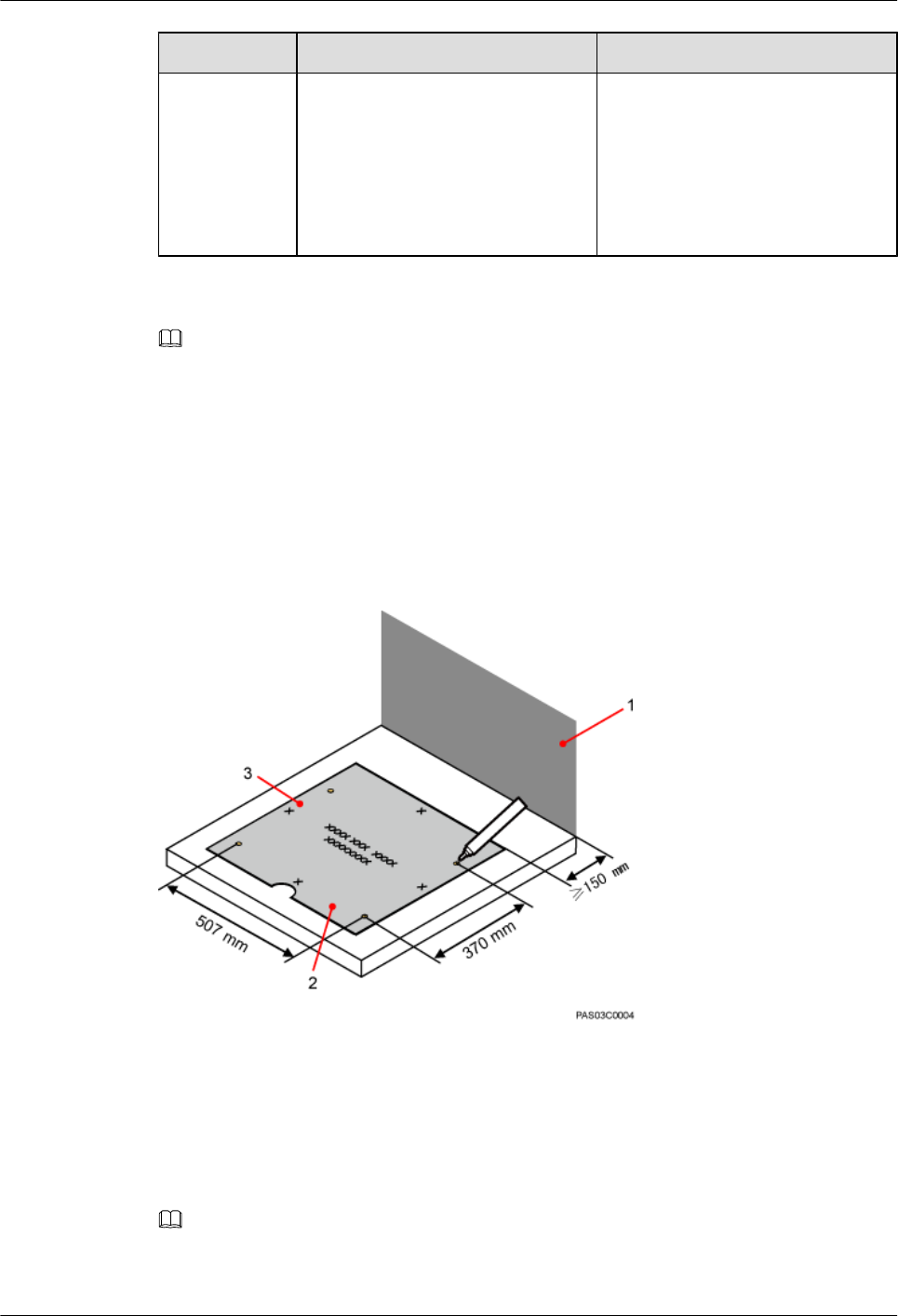
Step 1 Place the marking-off template on the ESD floor. Then use a marker to mark four anchor points,
as shown in Figure 8-7.
Figure 8-7 Marking anchor points
(1) Wall (2) Front (3) Left
Step 2 Drill holes on the ESD floor, as shown in Figure 8-8. Ensure that the hammer drill penetrates
the ESD floor.
NOTE
Use a vacuum cleaner to clear the dust out from inside and around all the holes, and measure the distances
between holes. If any hole does not meet the requirements, mark new anchor points and drill new holes.
DBS3900 (ICR)
Installation Guide 8 Installing the IFS06
Issue 12 (2015-04-30) Huawei Proprietary and Confidential
Copyright © Huawei Technologies Co., Ltd.
66
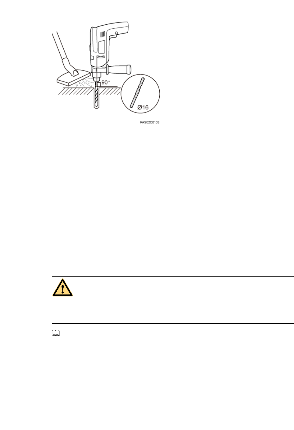
Figure 8-8 Drilling holes
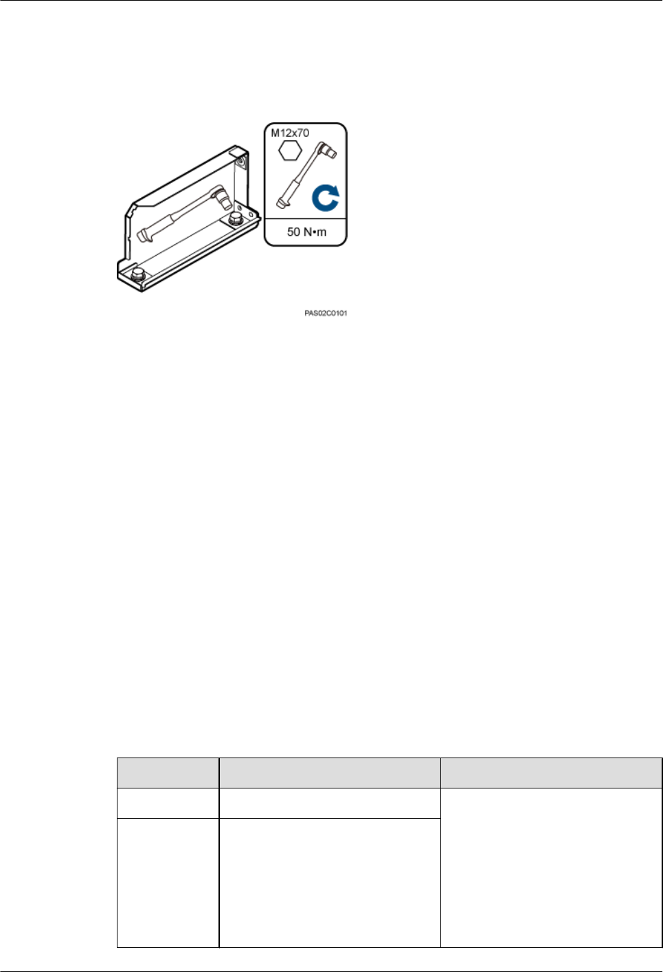
Step 3 Drill holes on the concrete floor, as shown in Figure 8-9.
1. Place the support under the ESD floor, and use M12x70 bolts to fix the ESD floor to the
support temporarily.
2. According to the support's mounting hole for the concrete floor, use a marker to mark the
positions for installing expansion bolts.
3. Use a measuring tape to measure the inter-hole spacing, and ensure that the center-to-center
separations of the holes are consistent.
Figure 8-9 Fixing the support to the ESD floor
(1) Mounting holes on the ESD floor (2) ESD floor (3) Mounting holes for the concrete floor
Step 4 Drill holes at the anchor points and install expansion bolt assemblies in the holes, as shown in
the following figure.
CAUTION
Take proper safety measures to protect your eyes and respiratory tract against the dust before
drilling holes.
NOTE
Generally, the concrete floor is solid and smooth. Therefore, you can use the center punch to help locate
the drill bit. If the conditions of the floor allow direct drilling, skip this step.
DBS3900 (ICR)
Installation Guide 8 Installing the IFS06
Issue 12 (2015-04-30) Huawei Proprietary and Confidential
Copyright © Huawei Technologies Co., Ltd.
67
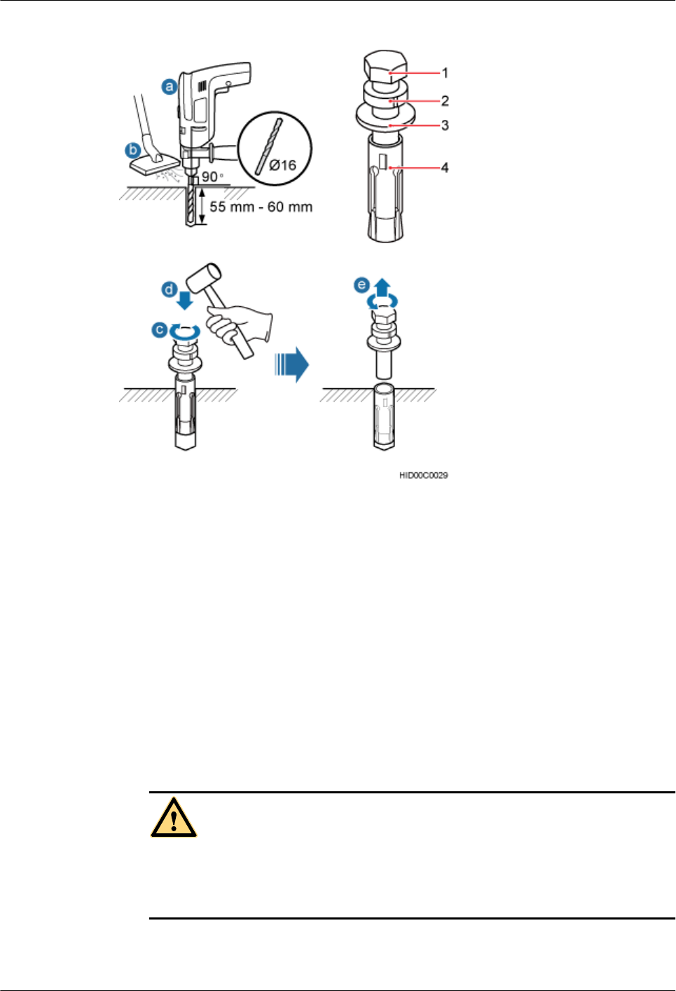
Figure 8-10 Drilling a hole and inserting an expansion bolt assembly
(1) M12x60 bolts (2) Spring washer (3) Flat washer (4) Expansion tube
1. Use a hammer drill with a Φ16 drill bit to drill holes with a depth ranging from 55 mm
(2.05 in.) to 60 mm (2.36 in.).
2. Use a vacuum cleaner to clear the dust out from inside and around the holes, and measure
the distances between holes. If any of the hole is beyond the acceptable range, mark a new
anchor point and drill a new hole.
3. Tighten an expansion bolt slightly and place it vertically into each hole.
4. Hit the expansion bolt with a rubber mallet until the expansion tube completely enters the
hole.
5. Turning the M12x60 bolt, spring washer, and flat washer counterclockwise, and remove
them in sequence.
CAUTION
After dismantling the expansion bolt assembly, ensure that the top of the expansion tube
is level with the concrete floor. Otherwise, the cabinet cannot be installed on the concrete
floor evenly and securely.
Step 5 Use a level to measure all sides of the frame and use spacers to level the frame if necessary, as
shown in Figure 8-11.
DBS3900 (ICR)
Installation Guide 8 Installing the IFS06
Issue 12 (2015-04-30) Huawei Proprietary and Confidential
Copyright © Huawei Technologies Co., Ltd.
68
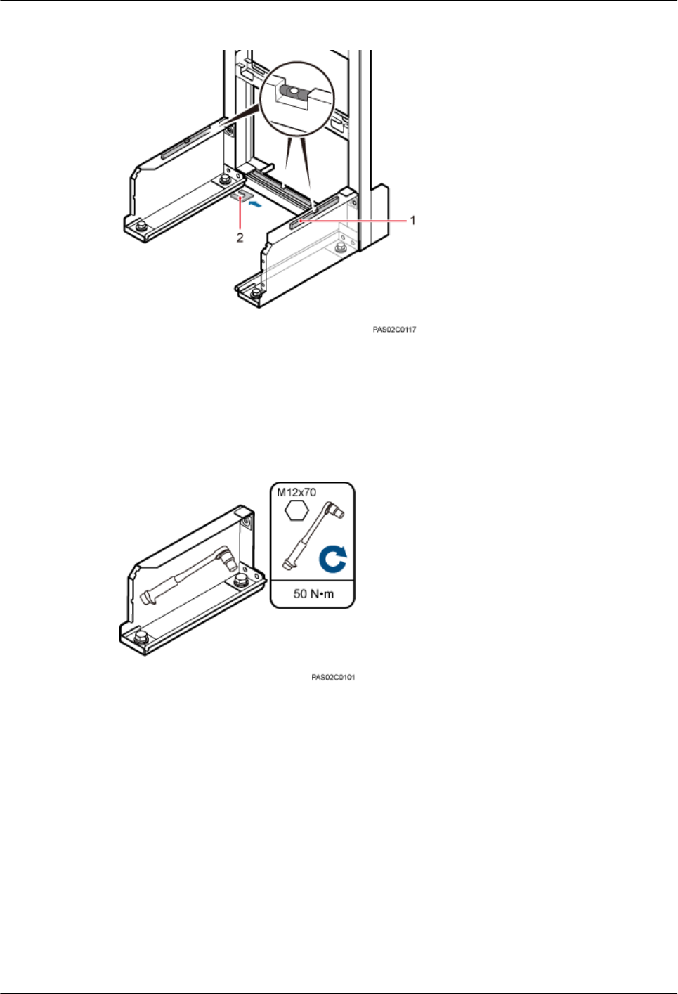
Figure 8-11 Checking and leveling the IFS06
(1) Level (2) Spacer
Step 6 Use a socket wrench to tighten the bolts to 50 N·m (442.54 lbf·in.), as shown in Figure 8-12.
Figure 8-12 Tightening the bolts
----End
DBS3900 (ICR)
Installation Guide 8 Installing the IFS06
Issue 12 (2015-04-30) Huawei Proprietary and Confidential
Copyright © Huawei Technologies Co., Ltd.
69

9 Installing the Main Brackets for RRUs
About This Chapter
This chapter describes the procedures for installing the main brackets for DC RRUs and AC
RRUs.
9.1 Introduction to the Bracket Assembly
This section describes the bracket assembly.
9.2 Installing the Main Brackets for DC RRUs
This section describes the procedure for installing the main brackets for DC RRUs.
9.3 Installing the Main Brackets for AC RRUs
This section describes the procedure for installing the main brackets for AC RRUs.
DBS3900 (ICR)
Installation Guide 9 Installing the Main Brackets for RRUs
Issue 12 (2015-04-30) Huawei Proprietary and Confidential
Copyright © Huawei Technologies Co., Ltd.
70
9.1 Introduction to the Bracket Assembly
This section describes the bracket assembly.
Bracket assembly has three kinds, Figure 9-1, Figure 9-2 and Figure 9-3 shows a bracket
assembly.
NOTE
Only the main bracket is required for installing an RRU on an IFS06.
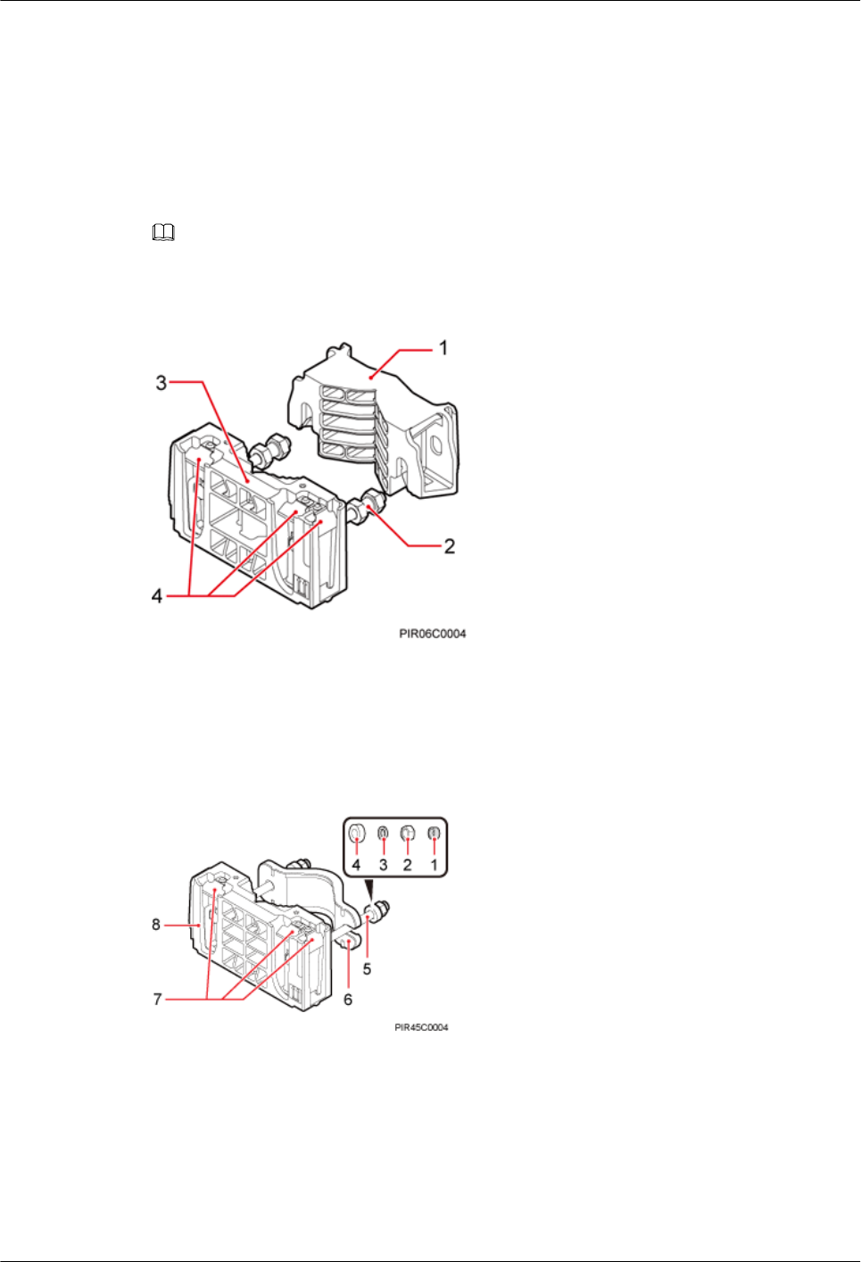
Figure 9-1 Bracket assembly (1)
(1) Auxiliary bracket (2) Dual-headed nut (3) Main bracket (4) Hoist clamp on the main bracket
Figure 9-2 Bracket assembly (2)
(1) Plastic cap (2) Standard M10 nut (3) Spring washer (4) Thick flat washer
(5) M10x150 bolt (6) Auxiliary bracket (7) Hoist clamp on the main bracket (8) Main bracket
DBS3900 (ICR)
Installation Guide 9 Installing the Main Brackets for RRUs
Issue 12 (2015-04-30) Huawei Proprietary and Confidential
Copyright © Huawei Technologies Co., Ltd.
71
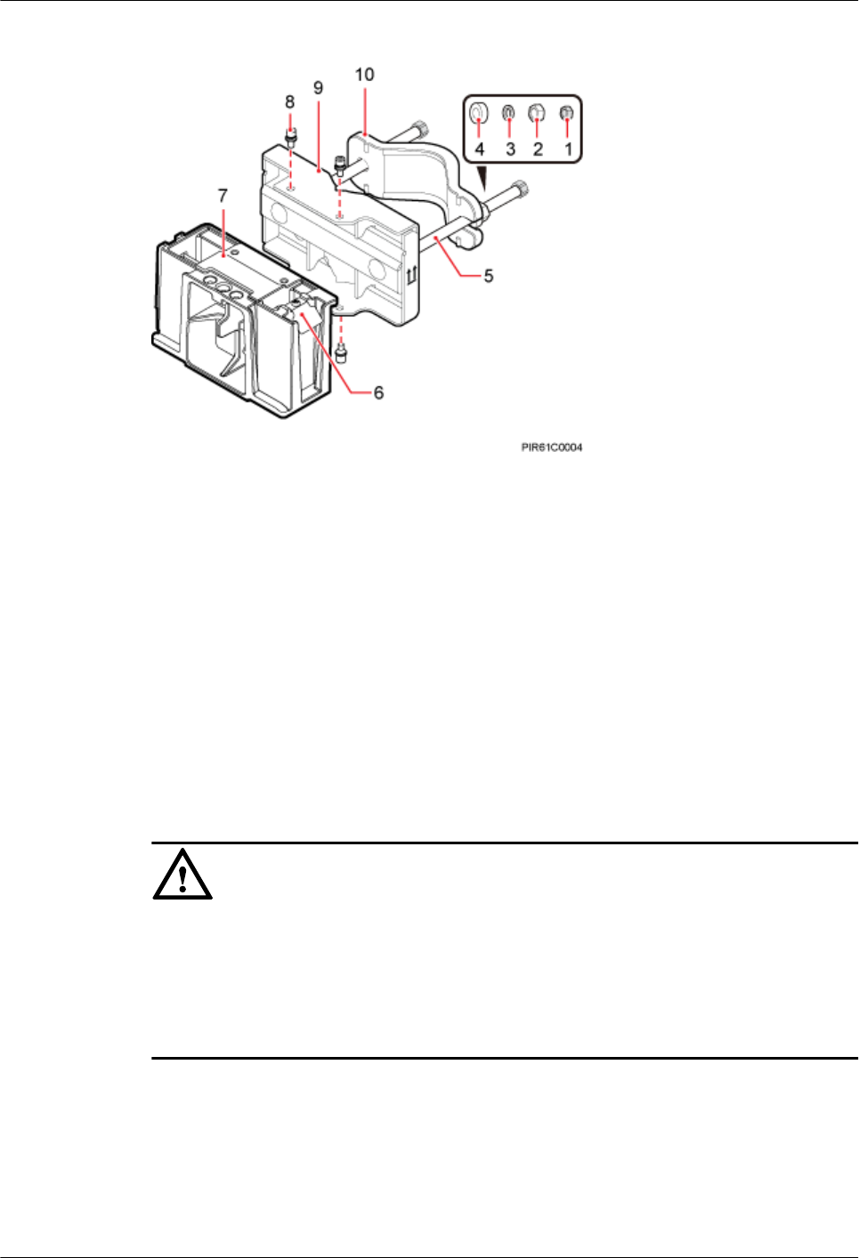
Figure 9-3 Bracket assembly (3)
(1) Plastic cap (2) Standard M10 nut (3) Spring washer (4) Thick flat washer (5) Square-neck bolt
(6) Hoist clamp on
the main bracket
(7) Main bracket (8) Inner hexagon
screw
(9) Pole installation
bracket
(10) Auxiliary
bracket
9.2 Installing the Main Brackets for DC RRUs
This section describes the procedure for installing the main brackets for DC RRUs.
Context
NOTICE
lUse the M10x50 bolts delivered with the IFS06 to install the main brackets for DC RRUs.
lInstall RRUs in the sequence from bottom to top and from left to right.
lEnsure that the contact pieces on the main brackets are locked before RRUs are mounted.
lRubber washers are easily compressed or broken, whereas do not need to be replaced.
Procedure
lHeight-unrestricted scenarios
Install the main brackets according to the label on the IFS06, as shown in Figure 9-4.
DBS3900 (ICR)
Installation Guide 9 Installing the Main Brackets for RRUs
Issue 12 (2015-04-30) Huawei Proprietary and Confidential
Copyright © Huawei Technologies Co., Ltd.
72
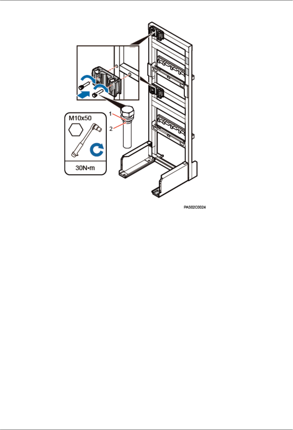
Figure 9-4 Installing the main brackets in height-unrestricted scenarios
(1) Spring washer (2) Rubber washer
lHeight-restricted scenarios
Use one of your fingers to push and remove the rubber plugs on the beam and install the
main brackets according to the label on the IFS06, as shown in Figure 9-5.
DBS3900 (ICR)
Installation Guide 9 Installing the Main Brackets for RRUs
Issue 12 (2015-04-30) Huawei Proprietary and Confidential
Copyright © Huawei Technologies Co., Ltd.
73
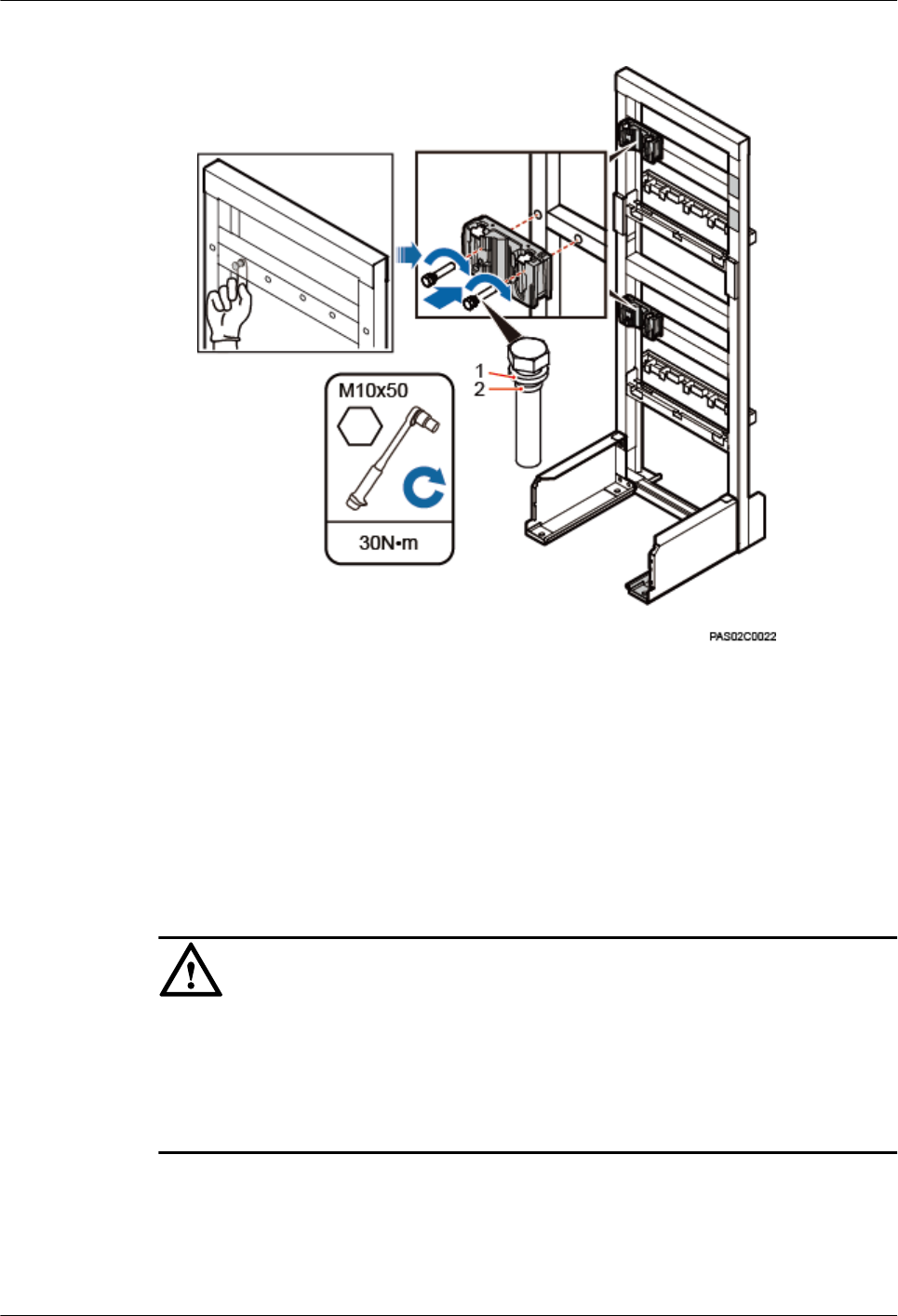
Figure 9-5 Installing the main brackets in height-restricted scenarios
(1) Spring washer (2) Rubber washer
----End
9.3 Installing the Main Brackets for AC RRUs
This section describes the procedure for installing the main brackets for AC RRUs.
Context
NOTICE
lUse the M10x50 bolts delivered with the IFS06 to install the main brackets for AC RRUs.
lInstall RRUs in the sequence from bottom to top and from left to right.
lEnsure that the contact pieces on the main brackets are locked before RRUs are mounted.
lRubber washers are easily compressed or broken, whereas do not need to be replaced.
Procedure
lHeight-unrestricted scenarios
Install the main brackets according to the label on the IFS06, as shown in Figure 9-6.
DBS3900 (ICR)
Installation Guide 9 Installing the Main Brackets for RRUs
Issue 12 (2015-04-30) Huawei Proprietary and Confidential
Copyright © Huawei Technologies Co., Ltd.
74
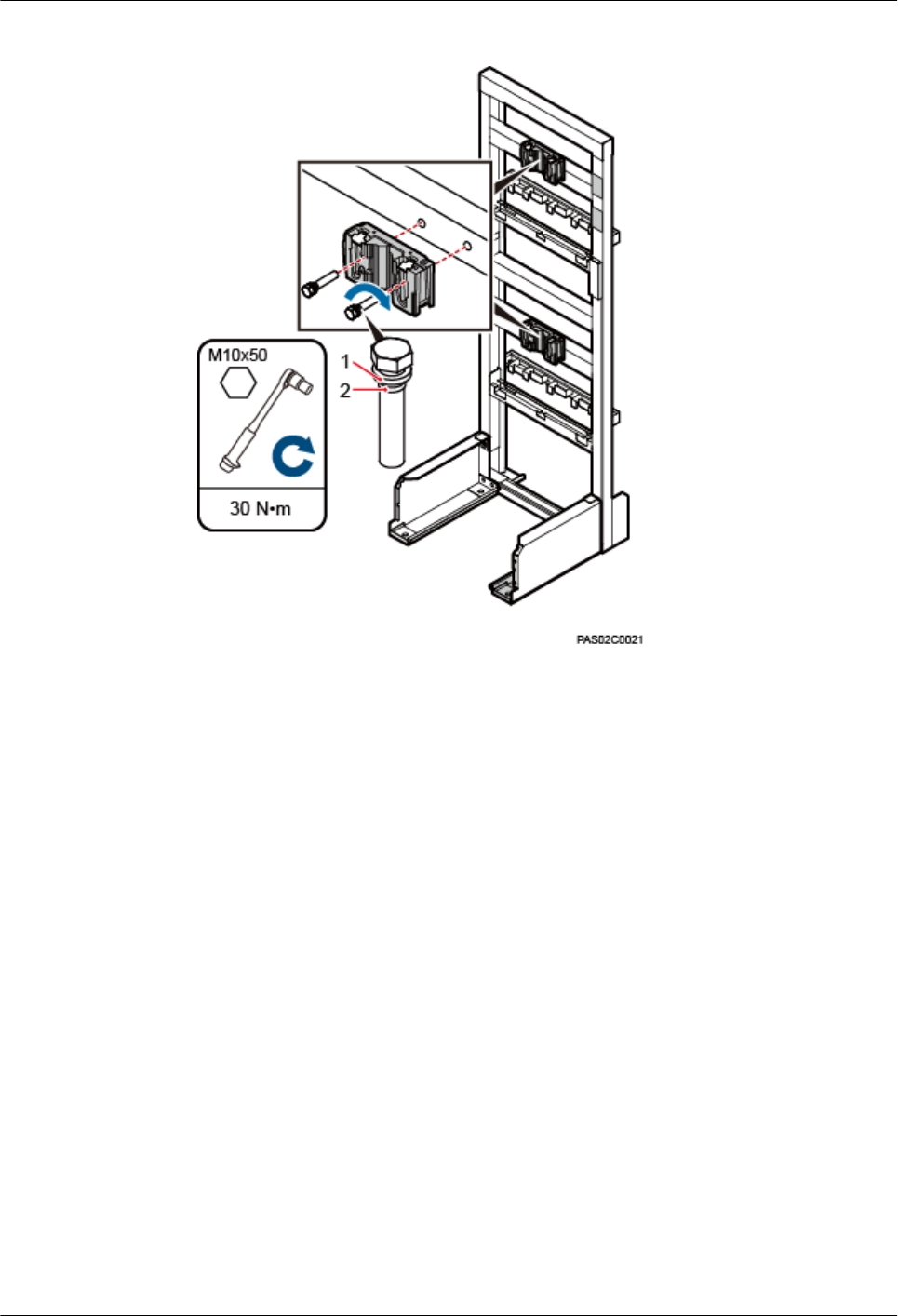
Figure 9-6 Installing the main brackets in height-unrestricted scenarios
(1) Spring washer (2) Rubber washer
lHeight-restricted scenarios
Use one of your fingers to push and remove the rubber plugs on the beam and install the
main brackets according to the label on the IFS06, as shown in Figure 9-7.
DBS3900 (ICR)
Installation Guide 9 Installing the Main Brackets for RRUs
Issue 12 (2015-04-30) Huawei Proprietary and Confidential
Copyright © Huawei Technologies Co., Ltd.
75
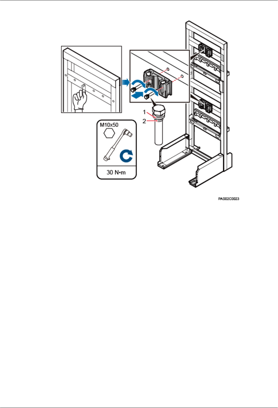
Figure 9-7 Installing the main brackets in height-restricted scenarios
(1) Spring washer (2) Rubber washer
----End
DBS3900 (ICR)
Installation Guide 9 Installing the Main Brackets for RRUs
Issue 12 (2015-04-30) Huawei Proprietary and Confidential
Copyright © Huawei Technologies Co., Ltd.
76
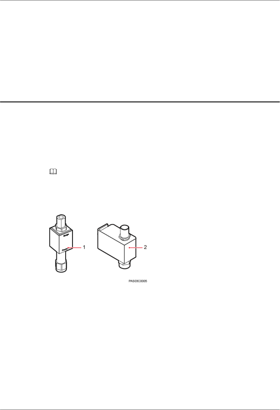
10 Installing the GPS Surge Protector
This chapter describes the procedure for installing the GPS surge protector.
Context
Two types of GPS surge protector can be installed on the IFS06, as shown in Figure 10-1.
NOTE
lOne or two GPS surge protectors can be installed on the IFS06, depending on the onsite requirements.
lGPS surge protector A does not require a PGND cable.
Figure 10-1 GPS surge protector
(1) GPS surge protector A (2) GPS surge protector B
Procedure
Step 1 Remove the nut and toothed washer from the type N female connector of the GPS clock signal
cable, as shown in Figure 10-2.
DBS3900 (ICR)
Installation Guide 10 Installing the GPS Surge Protector
Issue 12 (2015-04-30) Huawei Proprietary and Confidential
Copyright © Huawei Technologies Co., Ltd.
77
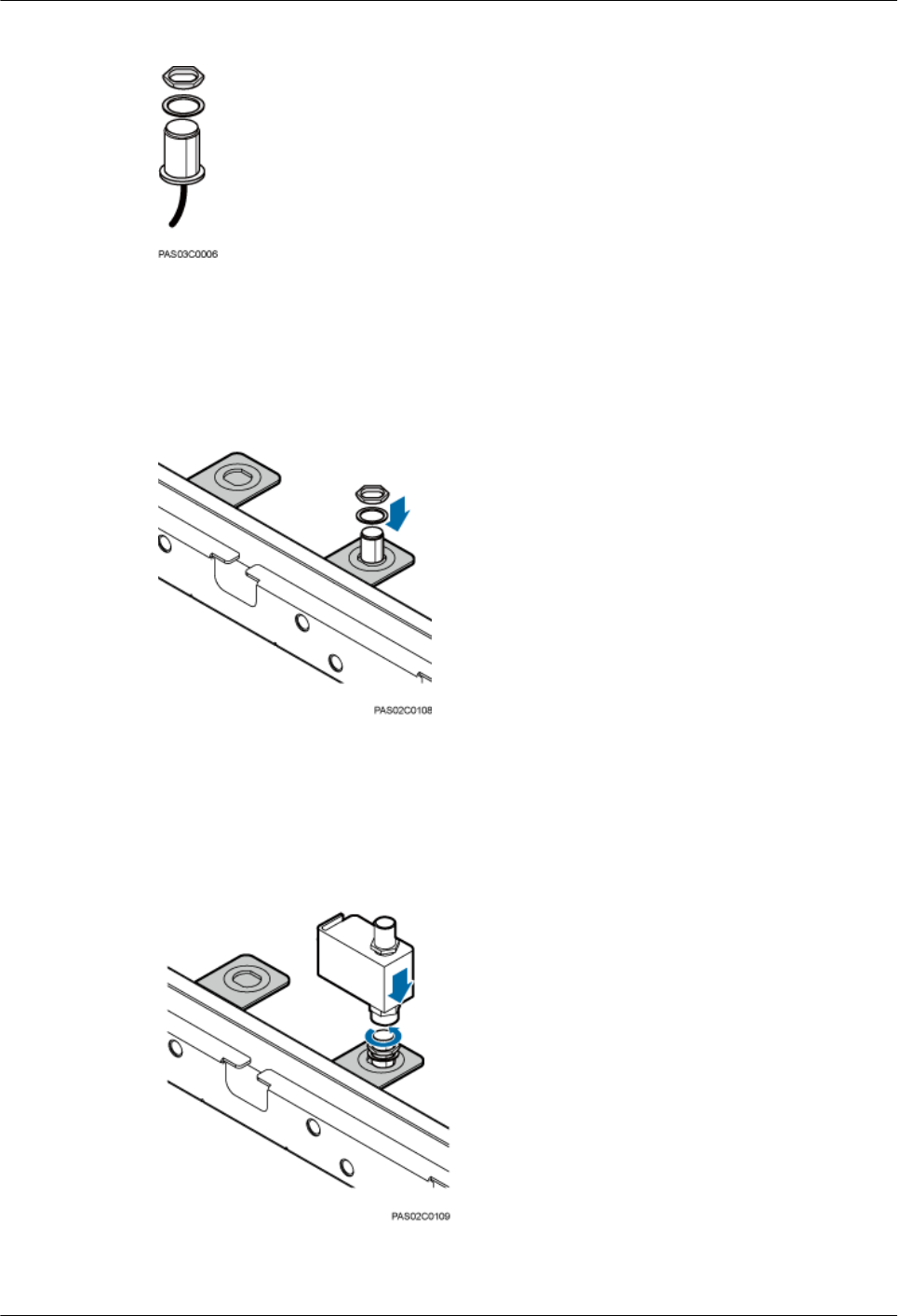
Figure 10-2 Removing the nut and toothed washer
Step 2 Fix the type N female connector of the GPS clock signal cable to the attachment plate, as shown
in Figure 10-3.
Figure 10-3 Installing the type N female connector
Step 3 Secure the GPS surge protector to the attachment plate. Partially tighten the GPS surge protector
with hands, and use an adjustable wrench to tighten it, as shown in Figure 10-4.
Figure 10-4 Installing the GPS surge protector
DBS3900 (ICR)
Installation Guide 10 Installing the GPS Surge Protector
Issue 12 (2015-04-30) Huawei Proprietary and Confidential
Copyright © Huawei Technologies Co., Ltd.
78
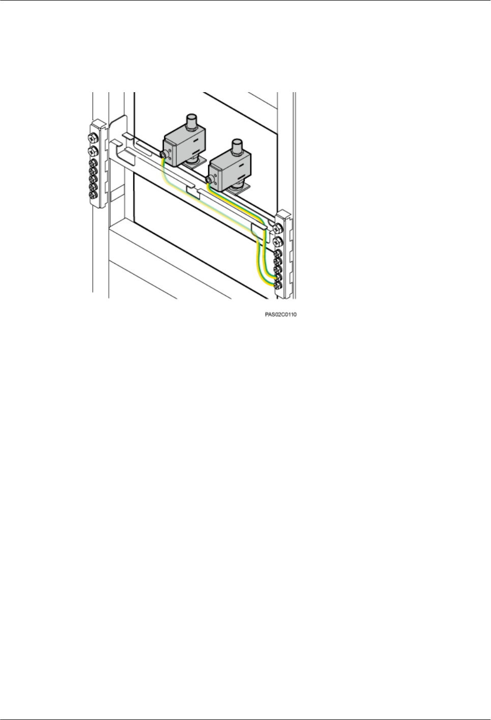
Step 4 Connect the OT terminal at one end of the PGND cable for the GPS surge protector to the ground
terminal on the GPS surge protector, and the other end of the PGND cable to the ground bar on
the IFS06, as shown in Figure 10-5.
Figure 10-5 Installing the PGND cable for the GPS surge protector
Step 5 Lay out the cables according to the instructions in 15.1 Cabling Requirements, and use cable
ties to bind the cables.
Step 6 Label the installed cables according to the instructions in Attaching a Sign Plate Label.
----End
DBS3900 (ICR)
Installation Guide 10 Installing the GPS Surge Protector
Issue 12 (2015-04-30) Huawei Proprietary and Confidential
Copyright © Huawei Technologies Co., Ltd.
79

11 Installing the IMB03
About This Chapter
This chapter describes the procedure for installing the IMB03.
11.1 Installing the Upper IMB03 Independently
This section describes the procedure for installing the upper IMB03 independently.
11.2 Installing the Lower IMB03 Independently
This section describes the procedure for installing the lower IMB03 independently.
11.3 Installing the IMB03s on the Upper and Lower Levels
This section describes the procedure for installing the IMB03s on the upper and lower levels.
DBS3900 (ICR)
Installation Guide 11 Installing the IMB03
Issue 12 (2015-04-30) Huawei Proprietary and Confidential
Copyright © Huawei Technologies Co., Ltd.
80
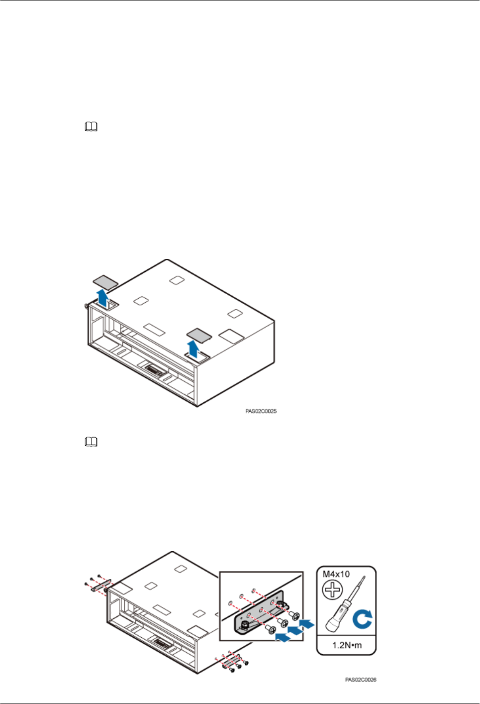
11.1 Installing the Upper IMB03 Independently
This section describes the procedure for installing the upper IMB03 independently.
Context
NOTE
The operations in this section apply to the scenario where only the upper IMB03 is required.
Procedure
Step 1 Use one of your fingers to push and remove the two protective plates on the top of the IMB03,
as shown in Figure 11-1.
Figure 11-1 Removing the protective plates
NOTE
After all cables are installed, if there is spare space in the cable holes, cut the protective plates to an
appropriate shape to seal the cable holes.
Step 2 Install two mounting ears horizontally on both sides of the IMB03 and tighten the three screws
on each side to 1.2 N·m (10.62 lbf·in.), as shown in Figure 11-2.
Figure 11-2 Installing mounting ears horizontally
DBS3900 (ICR)
Installation Guide 11 Installing the IMB03
Issue 12 (2015-04-30) Huawei Proprietary and Confidential
Copyright © Huawei Technologies Co., Ltd.
81
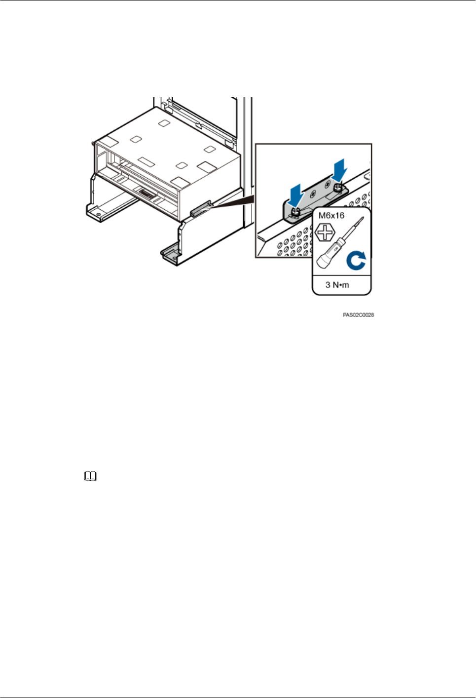
Step 3 Place the IMB03 on the feet and tighten the two screws on both feet to secure the IMB03 onto
the ICR, with a torque of 3 N·m (26.55 lbf·in.), as shown in Figure 11-3.
Figure 11-3 Securing the IMB03 to the feet of the ICR
----End
11.2 Installing the Lower IMB03 Independently
This section describes the procedure for installing the lower IMB03 independently.
Context
NOTE
The operations in this section apply to the scenario where only the lower IMB03 is required.
Procedure
Step 1 Use one of your fingers to push and remove the two protective plates on the top of the lower
IMB03, as shown in Figure 11-4.
DBS3900 (ICR)
Installation Guide 11 Installing the IMB03
Issue 12 (2015-04-30) Huawei Proprietary and Confidential
Copyright © Huawei Technologies Co., Ltd.
82
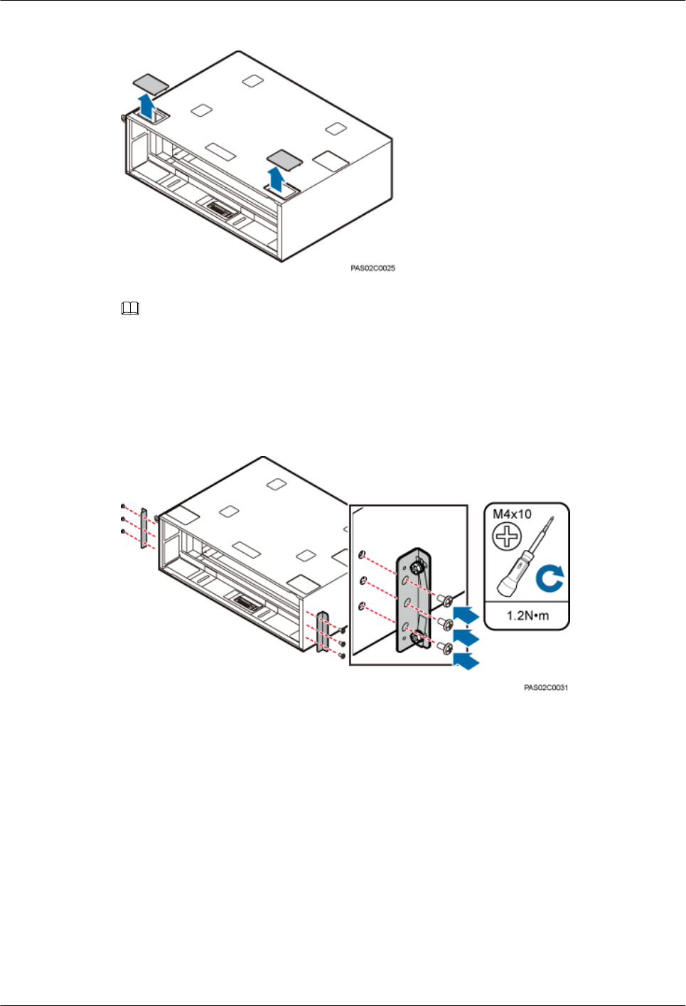
Figure 11-4 Removing the protective plates
NOTE
After all cables are installed, if there is spare space in the cable holes, cut the protective plates to an
appropriate shape to seal the cable holes.
Step 2 Install two mounting ears vertically on both sides of the IMB03 and tighten the three screws on
each side to 1.2 N·m (10.62 lbf·in.), as shown in Figure 11-5.
Figure 11-5 Installing mounting ears vertically
Step 3 Place the IMB03 in between the feet and tighten the two screws on both feet to secure the IMB03
onto the ICR, with a torque of 3 N·m (26.55 lbf·in.), as shown in Figure 11-6.
DBS3900 (ICR)
Installation Guide 11 Installing the IMB03
Issue 12 (2015-04-30) Huawei Proprietary and Confidential
Copyright © Huawei Technologies Co., Ltd.
83
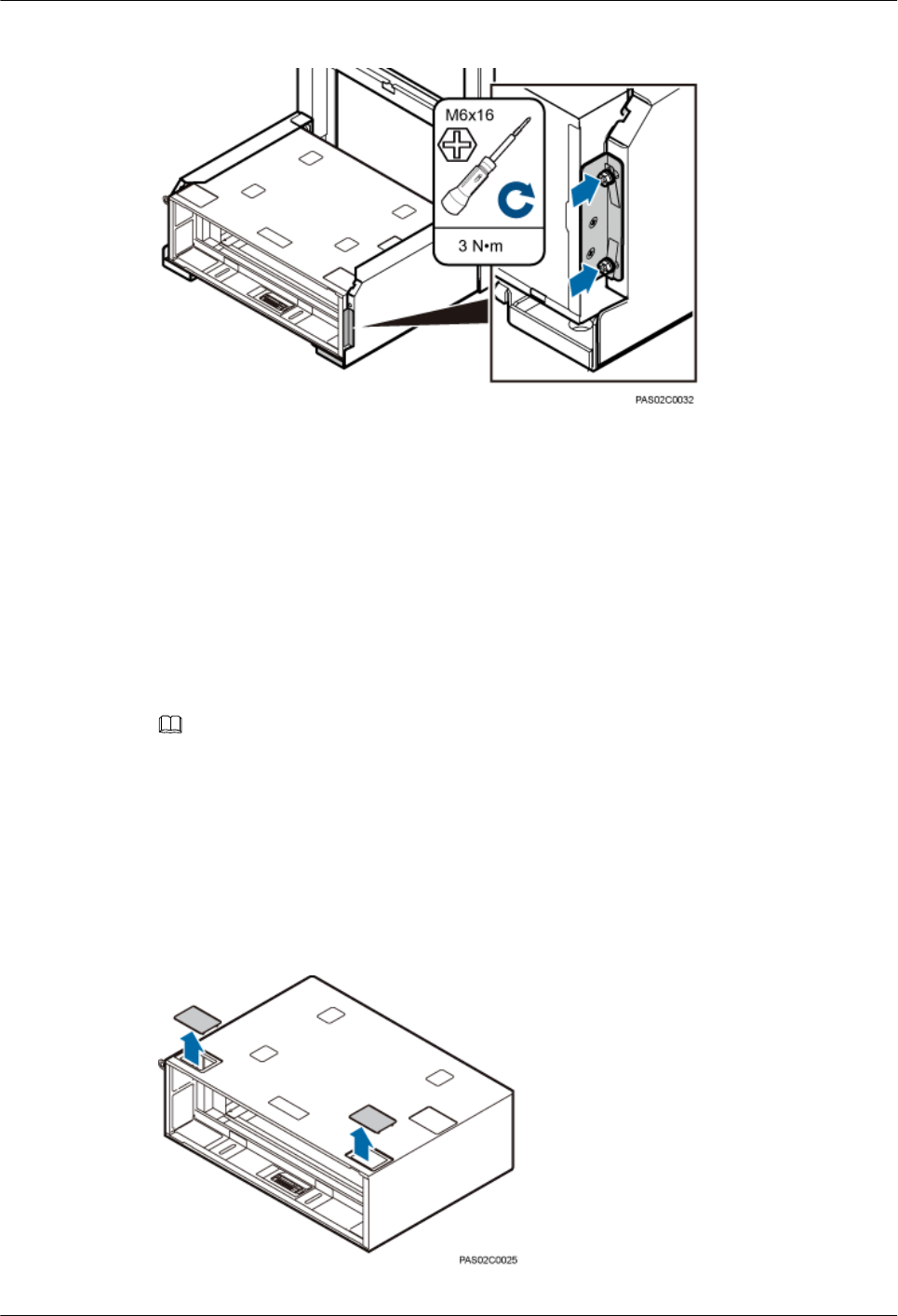
Figure 11-6 Securing the IMB03 to the feet of the ICR
----End
11.3 Installing the IMB03s on the Upper and Lower Levels
This section describes the procedure for installing the IMB03s on the upper and lower levels.
Context
NOTE
To install two IMB03s on an ICR, install the lower IMB03 first and then the upper IMB03.
Procedure
Step 1 Use one of your fingers to push and remove the two protective plates on the top of the lower
IMB03, as shown in Figure 11-7.
Figure 11-7 Removing the protective plates
DBS3900 (ICR)
Installation Guide 11 Installing the IMB03
Issue 12 (2015-04-30) Huawei Proprietary and Confidential
Copyright © Huawei Technologies Co., Ltd.
84
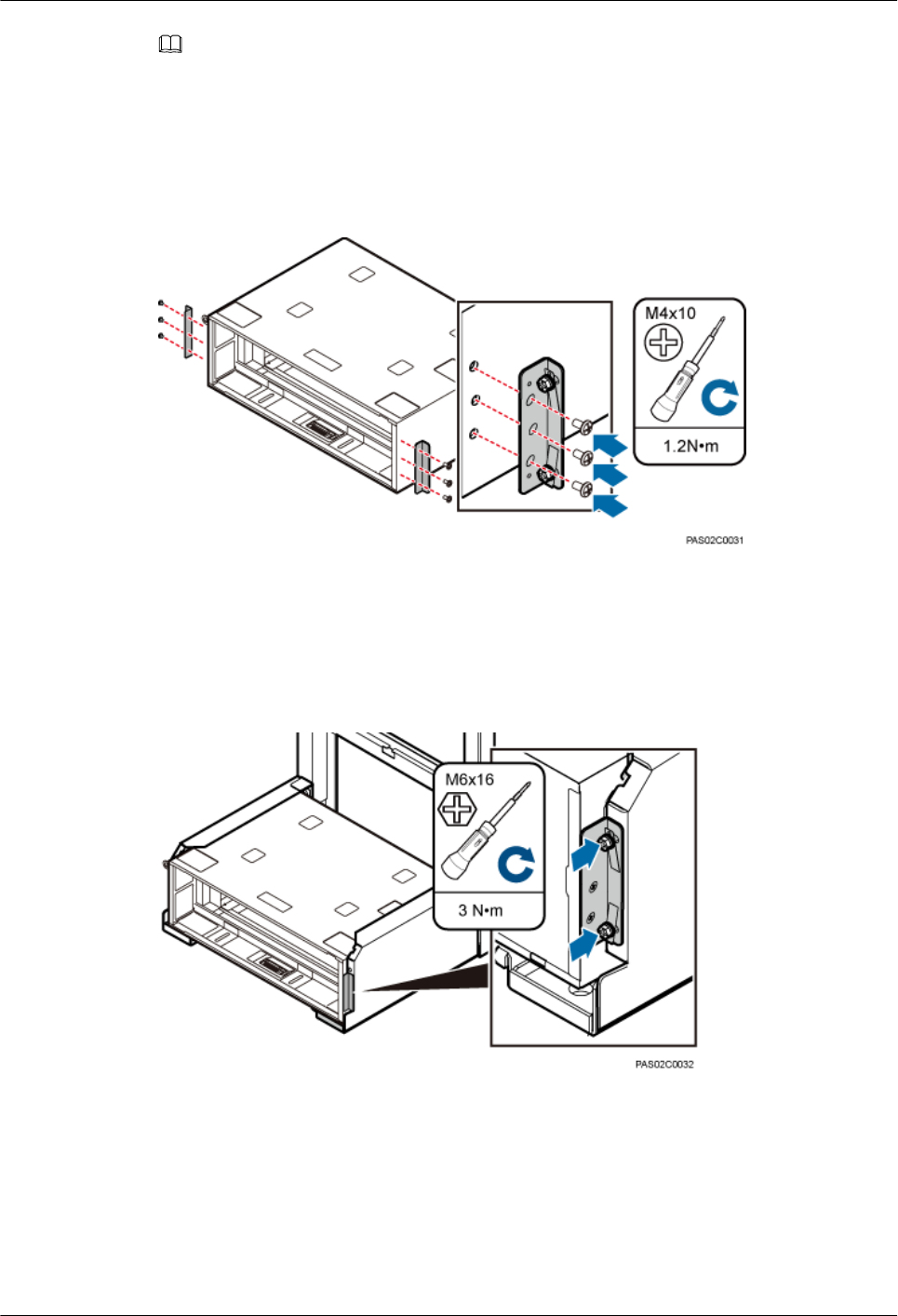
NOTE
After all cables are installed, if there is spare space in the cable holes, cut the protective plates to an
appropriate shape to seal the cable holes.
Step 2 Install two mounting ears vertically on both sides of the IMB03 and tighten the three screws on
each side to 1.2 N·m (10.62 lbf·in.), as shown in Figure 11-8.
Figure 11-8 Installing mounting ears vertically
Step 3 Place the IMB03 in between the feet and tighten the two screws on both feet to secure the IMB03
onto the ICR, with a torque of 3 N·m (26.55 lbf·in.), as shown in Figure 11-9.
Figure 11-9 Securing the IMB03 to the feet of the ICR
Step 4 Use one of your fingers to push and remove the two protective plates on the top and two protective
plates at the bottom of the upper IMB03, as shown in Figure 11-10.
DBS3900 (ICR)
Installation Guide 11 Installing the IMB03
Issue 12 (2015-04-30) Huawei Proprietary and Confidential
Copyright © Huawei Technologies Co., Ltd.
85
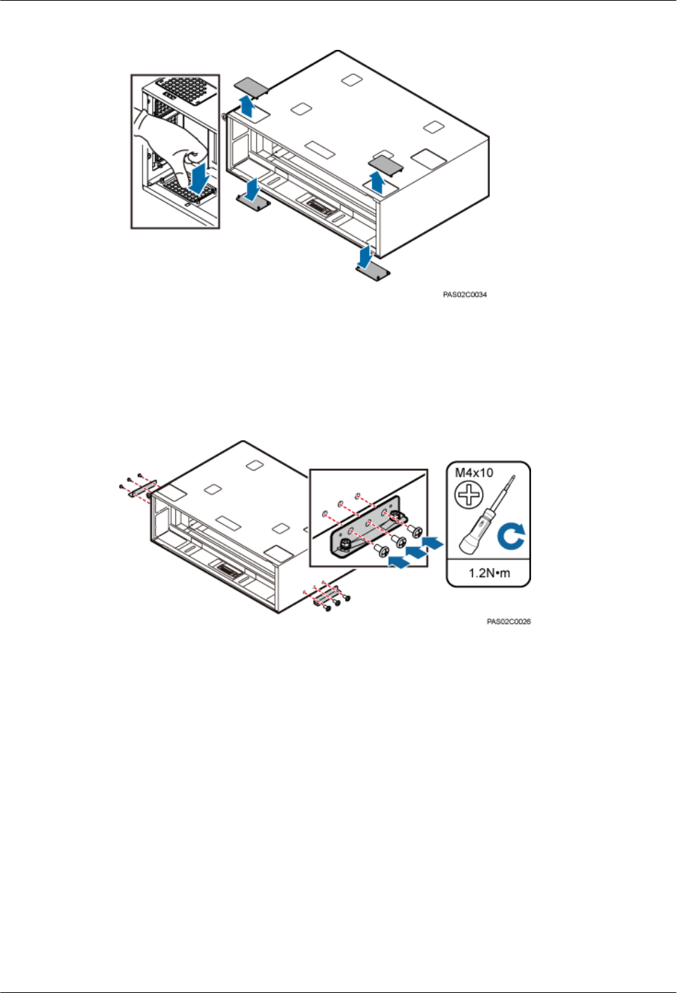
Figure 11-10 Removing the protective plates from the upper IMB03
Step 5 Install two mounting ears horizontally on both sides of the IMB03 and tighten the three screws
on each side to 1.2 N·m (10.62 lbf·in.), as shown in Figure 11-11.
Figure 11-11 Installing mounting ears horizontally
Step 6 Place the IMB03 on the feet and tighten the two screws on each foot to secure the IMB03 onto
the ICR, with a torque of 3 N·m (26.55 lbf·in.), as shown in Figure 11-12.
DBS3900 (ICR)
Installation Guide 11 Installing the IMB03
Issue 12 (2015-04-30) Huawei Proprietary and Confidential
Copyright © Huawei Technologies Co., Ltd.
86
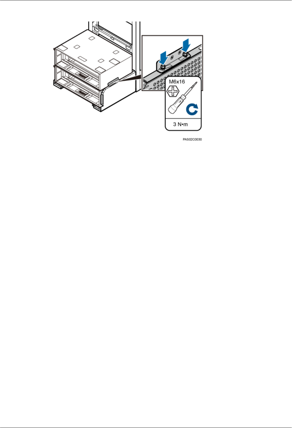
Figure 11-12 Securing the IMB03 to the feet of the ICR
----End
DBS3900 (ICR)
Installation Guide 11 Installing the IMB03
Issue 12 (2015-04-30) Huawei Proprietary and Confidential
Copyright © Huawei Technologies Co., Ltd.
87

12 Installing the Equipotential Cable and
PGND Cable
This chapter describes the procedures for installing the equipotential cable and PGND cable.
Prerequisites
A PGND cable and an equipotential cable need to be prepared onsite. Table 12-1 lists the
specifications of a PGND cable and an equipotential cable.
Table 12-1 Cable specifications
Cable Connector at One End Connector at the
Other End
Cross-Sectional Area
of the Cable
PGND cable OT terminal (M8) Depending on the
external ground bar
16 mm2 (0.025 in.2)
Equipotential
cable between the
IFS06 and the
IMB03
OT terminal (M6) OT terminal (M6) 16 mm2 (0.025 in.2)
Equipotential
cable between the
upper and lower
IMB03s
OT terminal (M4) OT terminal (M4) 6 mm2 (0.009 in.2)
Procedure
Step 1 Cut the cable to a length suitable for the actual cable route.
Step 2 Add an OT terminal to each end of the cable according to the instructions in Assembling the OT
Terminal and the Power Cable.
Step 3 Install the PGND cable and equipotential cable, as shown in Figure 12-1.
DBS3900 (ICR)
Installation Guide 12 Installing the Equipotential Cable and PGND Cable
Issue 12 (2015-04-30) Huawei Proprietary and Confidential
Copyright © Huawei Technologies Co., Ltd.
88
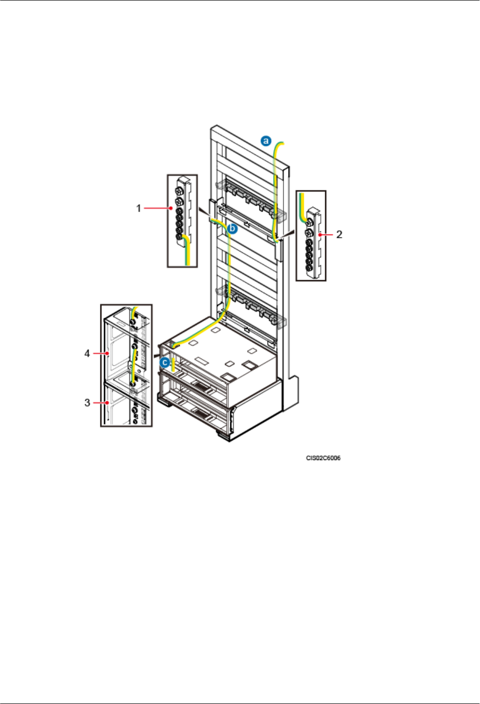
1. Connect one end of the PGND cable to ground bar 2 on the IFS06.
2. Connect one end of the equipotential cable to ground bar 1 on the IFS06 and the other end
to the ground bar on the upper IMB03.
3. Connect one end of the equipotential cable to the ground bar on the upper IMB03 and the
other end to the ground bar on the lower IMB03.
Figure 12-1 Installing a PGND cable and an equipotential cable
(1) Ground bar 1 (2) Ground bar 2 (3) Lower IMB03 (4) Upper IMB03
Step 4 Lay out the cables according to the instructions in 15.1 Cabling Requirements, and use cable
ties to bind the cables.
Step 5 Label the installed cables according to the instructions in Attaching a Cable-Tying Label.
----End
DBS3900 (ICR)
Installation Guide 12 Installing the Equipotential Cable and PGND Cable
Issue 12 (2015-04-30) Huawei Proprietary and Confidential
Copyright © Huawei Technologies Co., Ltd.
89

13 Installing Components in the IMB03
About This Chapter
This chapter describes the procedures for installing components in the IMB03.
13.1 Components in an IMB03
This section describes the components to be installed in an IMB03.
13.2 Installing the BBU
This chapter describes the procedure for installing the BBU in the IMB03.
13.3 Installing the DCDU-03B, DCDU-11B or DCDU-12B
This chapter describes the procedure for installing the DCDU-03B, DCDU-11B or DCDU-12B
in the IMB03.
13.4 (Optional) Installing the DC/DC Power System
This section describes the procedure for installing the DC/DC power system in the IMB03.
13.5 (Optional) Installing the AC/DC Power System
This section describes the procedure for installing the AC/DC power system in the IMB03.
DBS3900 (ICR)
Installation Guide 13 Installing Components in the IMB03
Issue 12 (2015-04-30) Huawei Proprietary and Confidential
Copyright © Huawei Technologies Co., Ltd.
90
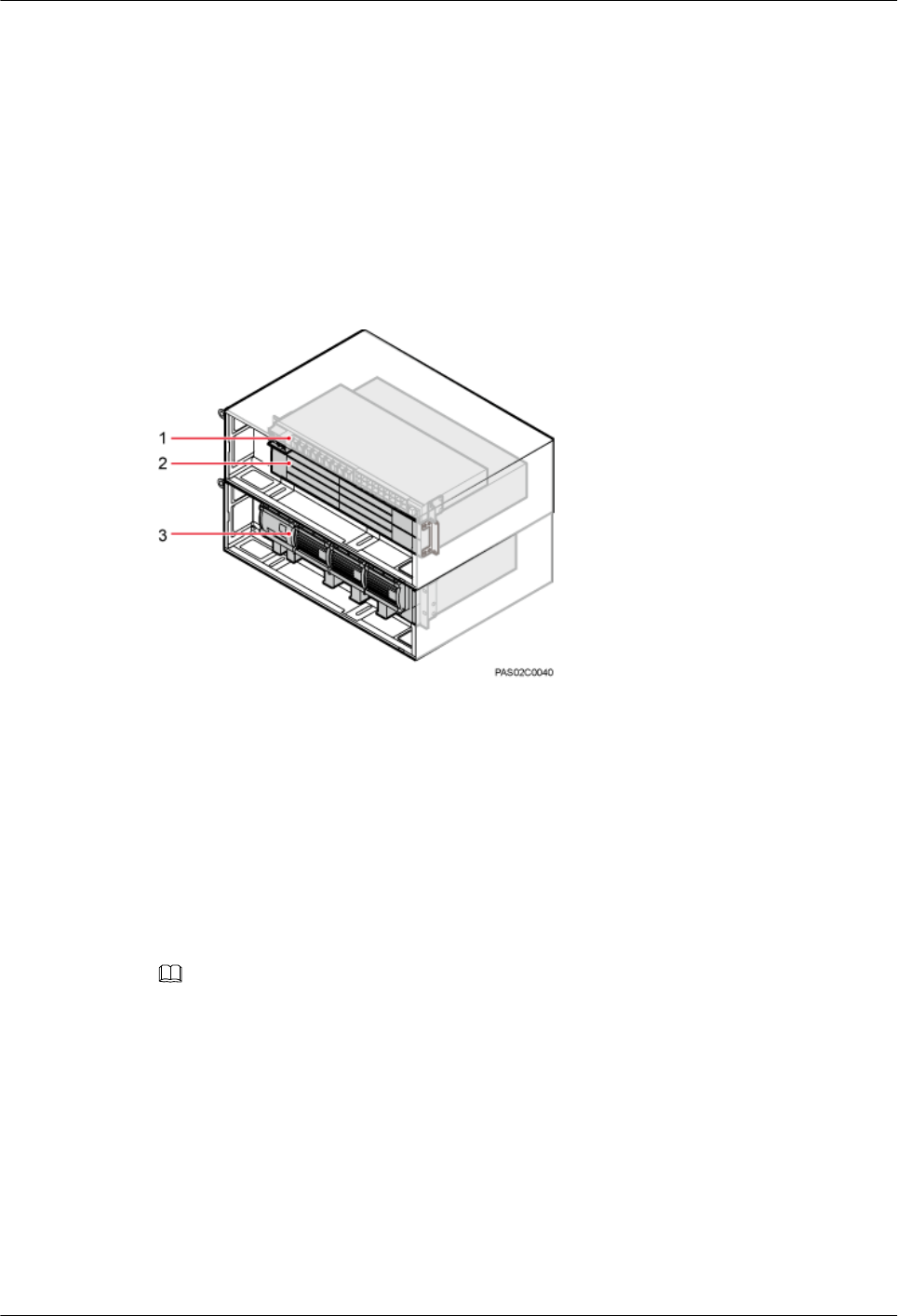
13.1 Components in an IMB03
This section describes the components to be installed in an IMB03.
See 3.2 Installation Scenarios for the number of required IMB03 subracks and the components
to be installed in each IMB03 subrack. Then see the slot assignment label in the IMB03 for the
component installation positions. Figure 13-1 shows the scenario where the DCDU, BBU, and
power devices are installed in two IMB03 subracks.
Figure 13-1 IMB03 slot assignment
(1) DCDU (2) BBU (3) Power device
13.2 Installing the BBU
This chapter describes the procedure for installing the BBU in the IMB03.
Context
NOTE
lThe BBU3900/BBU3910 has a left-in-right-out ventilation channel. It can be stacked with equipment using
a left-in-right-out ventilation channel but cannot be stacked with equipment using a right-in-left-out
ventilation channel.
lFor an indoor application, the BBU3900/BBU3910 can be installed in a standardized indoor equipment room
but cannot be installed in an equipment room using direct ventilation.
lFor an outdoor application, the BBU3900/BBU3910 can be installed in a cabinet using a heat exchanger but
cannot be installed in a cabinet using direct ventilation. For the specific cabinet types, see the related
hardware documentation.
Procedure
Step 1 Install a mounting ear reversely on each side of the BBU, as shown in Figure 13-2.
DBS3900 (ICR)
Installation Guide 13 Installing Components in the IMB03
Issue 12 (2015-04-30) Huawei Proprietary and Confidential
Copyright © Huawei Technologies Co., Ltd.
91
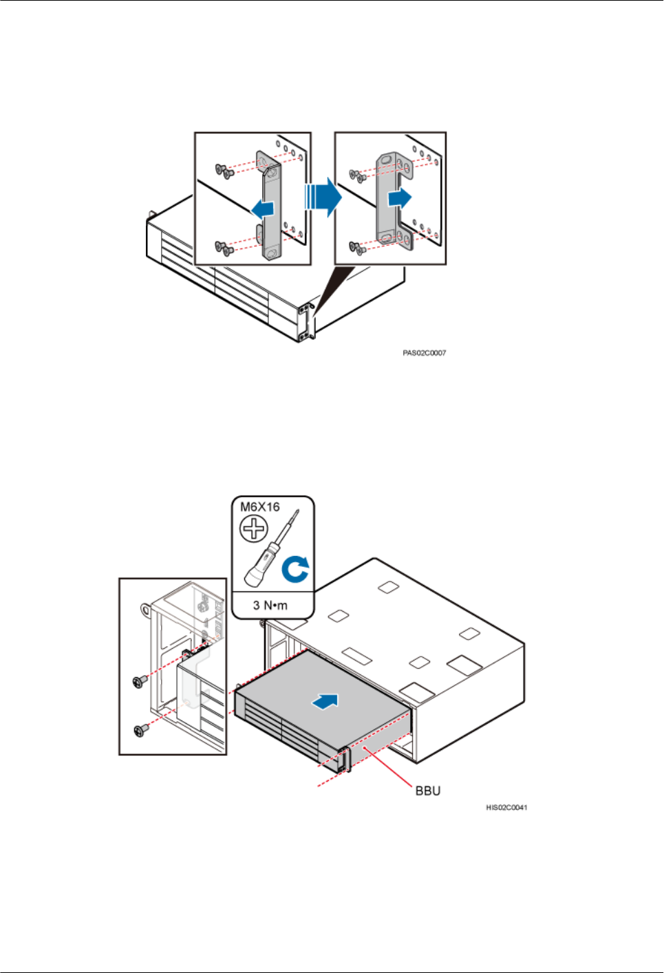
1. Remove the four M4 screws from the mounting ear on each side of the BBU.
2. Install the mounting ears reversely and tighten the four M4 screws on each of the mounting
ears, with a torque of 1.2 N·m (10.62 lbf·in.).
Figure 13-2 Installing mounting ears reversely
Step 2 Install the BBU into the corresponding slot in the IMB03. Then tighten the four M6x16 screws
on the mounting ears to 3 N·m (26.55 lbf·in.), as shown in Figure 13-3.
Figure 13-3 Installing the BBU
----End
DBS3900 (ICR)
Installation Guide 13 Installing Components in the IMB03
Issue 12 (2015-04-30) Huawei Proprietary and Confidential
Copyright © Huawei Technologies Co., Ltd.
92
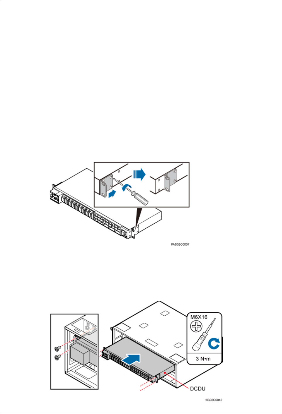
13.3 Installing the DCDU-03B, DCDU-11B or DCDU-12B
This chapter describes the procedure for installing the DCDU-03B, DCDU-11B or DCDU-12B
in the IMB03.
Context
The method of installing the DCDU-11B and DCDU-12B is the same as the method of installing
the DCDU-03B. This section uses the DCDU-03B as an example.
Procedure
Step 1 Move the mounting ears on the DCDU-03B, as shown in Figure 13-4.
1. Remove the four M4 screws from the mounting ear on each side of the DCDU-03B.
2. Move each mounting ear backwards by one hole and tighten the four removed M4 screws
on the mounting ear to 1.2 N·m (10.62 lbf·in.).
Figure 13-4 Installing the DCDU-03B
Step 2 Install the DCDU-03B into the corresponding slot in the IMB03. Then tighten the four M6x16
screws on the mounting ears to 3 N·m (26.55 lbf·in.), as shown in Figure 13-5.
Figure 13-5 Installing the DCDU-03B
DBS3900 (ICR)
Installation Guide 13 Installing Components in the IMB03
Issue 12 (2015-04-30) Huawei Proprietary and Confidential
Copyright © Huawei Technologies Co., Ltd.
93
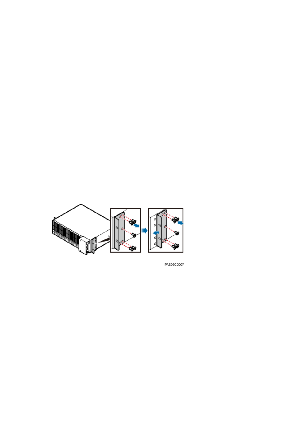
----End
13.4 (Optional) Installing the DC/DC Power System
This section describes the procedure for installing the DC/DC power system in the IMB03.
Context
The DC/DC power system needs to be installed in the scenarios with +24 V DC power supply.
Procedure
Step 1 Move the mounting ears on the DC/DC power system to the middle holes, as shown in Figure
13-6.
1. Remove the screws on the mounting ears on both sides of the DC/DC power system.
2. Move the mounting ears backwards to the middle holes.
3. Tighten the mounting ear on each side of the DC/DC power system to 1.2 N·m (10.62
lbf·in.).
Figure 13-6 Moving the mounting ears to the middle holes
Step 2 Install the DC/DC power system into the corresponding slot in the lower IMB03. Then tighten
the four M6x16 panel screws to 3 N·m (26.55 lbf·in.), as shown in Figure 13-7.
DBS3900 (ICR)
Installation Guide 13 Installing Components in the IMB03
Issue 12 (2015-04-30) Huawei Proprietary and Confidential
Copyright © Huawei Technologies Co., Ltd.
94
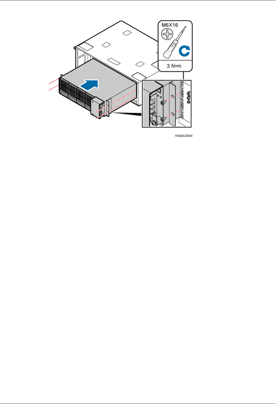
Figure 13-7 Installing the DC/DC power system
Step 3 Cut the PGND cable to a length suitable for the actual cable route.
Step 4 Add an OT terminal to each end of the cable according to the instructions in Assembling the OT
Terminal and the Power Cable.
Step 5 Connect the OT terminal (M6) at one end of the PGND cable to the DC/DC power system and
the OT terminal (M6) at other end to the IFS06, as shown in Figure 13-8.
DBS3900 (ICR)
Installation Guide 13 Installing Components in the IMB03
Issue 12 (2015-04-30) Huawei Proprietary and Confidential
Copyright © Huawei Technologies Co., Ltd.
95
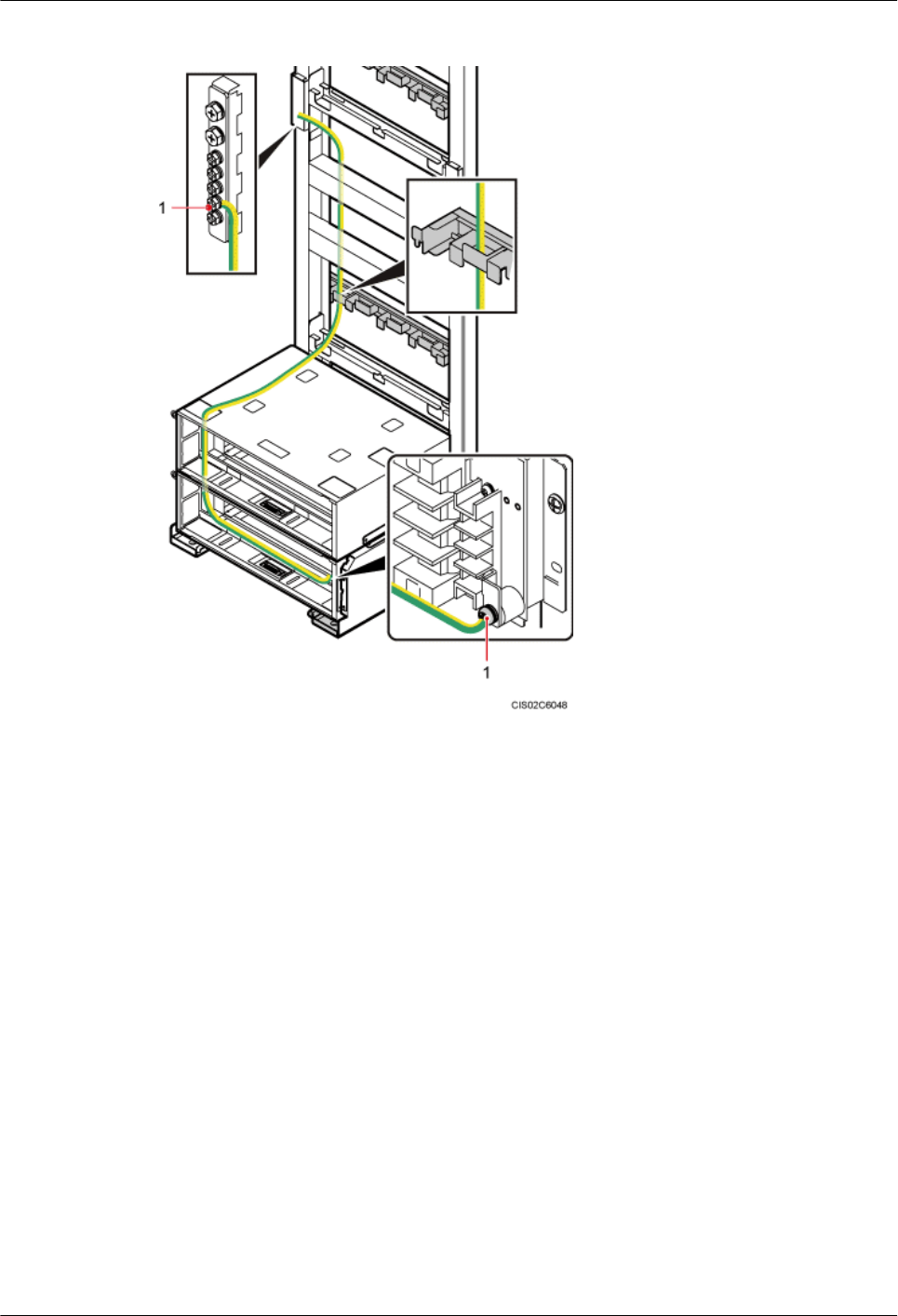
Figure 13-8 Installing the PGND cable for the DC/DC power system
(1) OT terminal (M6)
----End
13.5 (Optional) Installing the AC/DC Power System
This section describes the procedure for installing the AC/DC power system in the IMB03.
Context
The AC/DC power system needs to be installed in the scenarios with 220 V AC power supply.
Procedure
Step 1 Install the AC/DC power system into the corresponding slot in the lower IMB03. Then tighten
the four M6x16 panel screws to 3 N·m (26.55 lbf·in.), as shown in Figure 13-9.
DBS3900 (ICR)
Installation Guide 13 Installing Components in the IMB03
Issue 12 (2015-04-30) Huawei Proprietary and Confidential
Copyright © Huawei Technologies Co., Ltd.
96

Figure 13-9 Installing the AC/DC power system
Step 2 Cut the PGND cable to a length suitable for the actual cable route.
Step 3 Add an OT terminal to each end of the cable according to the instructions in Assembling the OT
Terminal and the Power Cable.
Step 4 Connect the OT terminal (M6) at one end of the PGND cable to the AC/DC power system and
the OT terminal (M6) at other end to the IFS06, as shown in Figure 13-10.
DBS3900 (ICR)
Installation Guide 13 Installing Components in the IMB03
Issue 12 (2015-04-30) Huawei Proprietary and Confidential
Copyright © Huawei Technologies Co., Ltd.
97
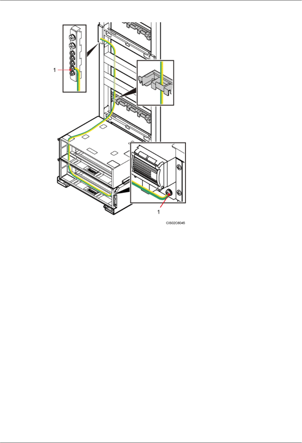
Figure 13-10 Installing the PGND cable for the AC/DC power system
(1) OT terminal (M6)
Step 5 Lay out the cable according to the instructions in 15.1 Cabling Requirements, and use cable
ties to bind the cable.
Step 6 Label the installed cable according to the instructions in Attaching a Cable-Tying Label.
----End
DBS3900 (ICR)
Installation Guide 13 Installing Components in the IMB03
Issue 12 (2015-04-30) Huawei Proprietary and Confidential
Copyright © Huawei Technologies Co., Ltd.
98

14 Installing RRUs
About This Chapter
This chapter describes the procedures for installing DC and AC RRUs.
14.1 Installing DC RRUs
This section describes the procedure for installing DC RRUs.
14.2 Installing AC RRUs
This section describes the procedure for installing AC RRUs.
DBS3900 (ICR)
Installation Guide 14 Installing RRUs
Issue 12 (2015-04-30) Huawei Proprietary and Confidential
Copyright © Huawei Technologies Co., Ltd.
99
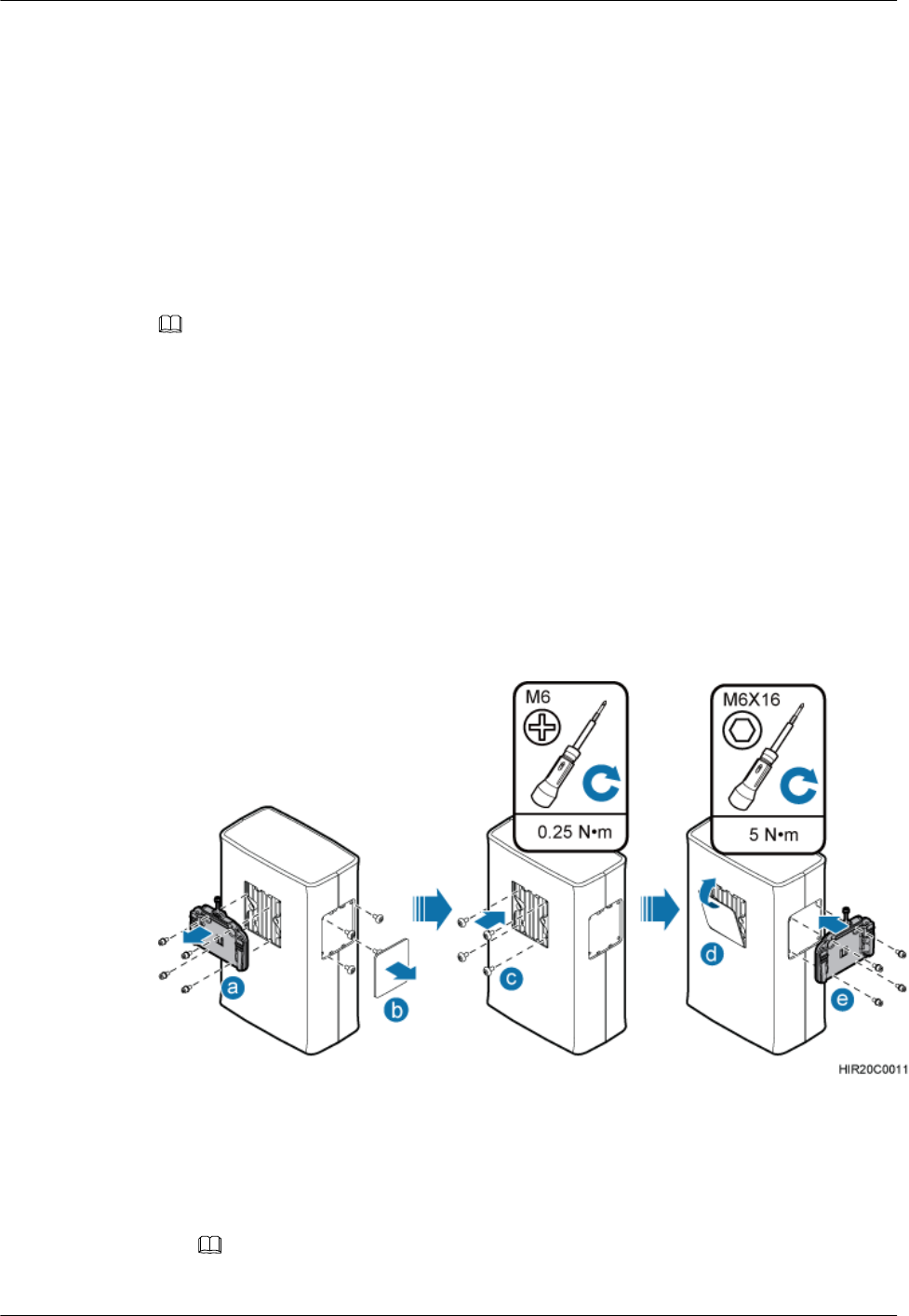
14.1 Installing DC RRUs
This section describes the procedure for installing DC RRUs.
Context
The method of installing DC RRUs in the IFS06+IMB03+RRU scenario is the same as the
method of installing DC RRUs in the IFS06+RRU scenario. This section uses the IFS06+RRU
scenario as an example.
NOTE
lPlace a foam pad or cardboard under an RRU to protect the RRU housing from damage during the
installation.
lDo not stand the RRU upright because the RF ports cannot support the weight of the RRU.
lThe bolts used for installing an attachment plate on one side of an RRU are the bolts removed from
the attachment plate at the rear of the RRU.
Procedure
Step 1 Interchange the attachment plate and stainless steel screws at the rear of the RRU and the cover
plate and plastic screws on one side of the RRU, as shown in Figure 14-1.
Figure 14-1 Interchanging the attachment plate at the rear of the RRU with the cover plate on
one side of the RRU
1. Use a hex key wrench to remove the attachment plate from the rear of the RRU.
2. Optional: Remove the cover plate from one side of the RRU, and use a Phillips screwdriver
to remove the plastic screws from the RRU.
NOTE
The plastic screws of some RRUs do not need to be removed.
DBS3900 (ICR)
Installation Guide 14 Installing RRUs
Issue 12 (2015-04-30) Huawei Proprietary and Confidential
Copyright © Huawei Technologies Co., Ltd.
100
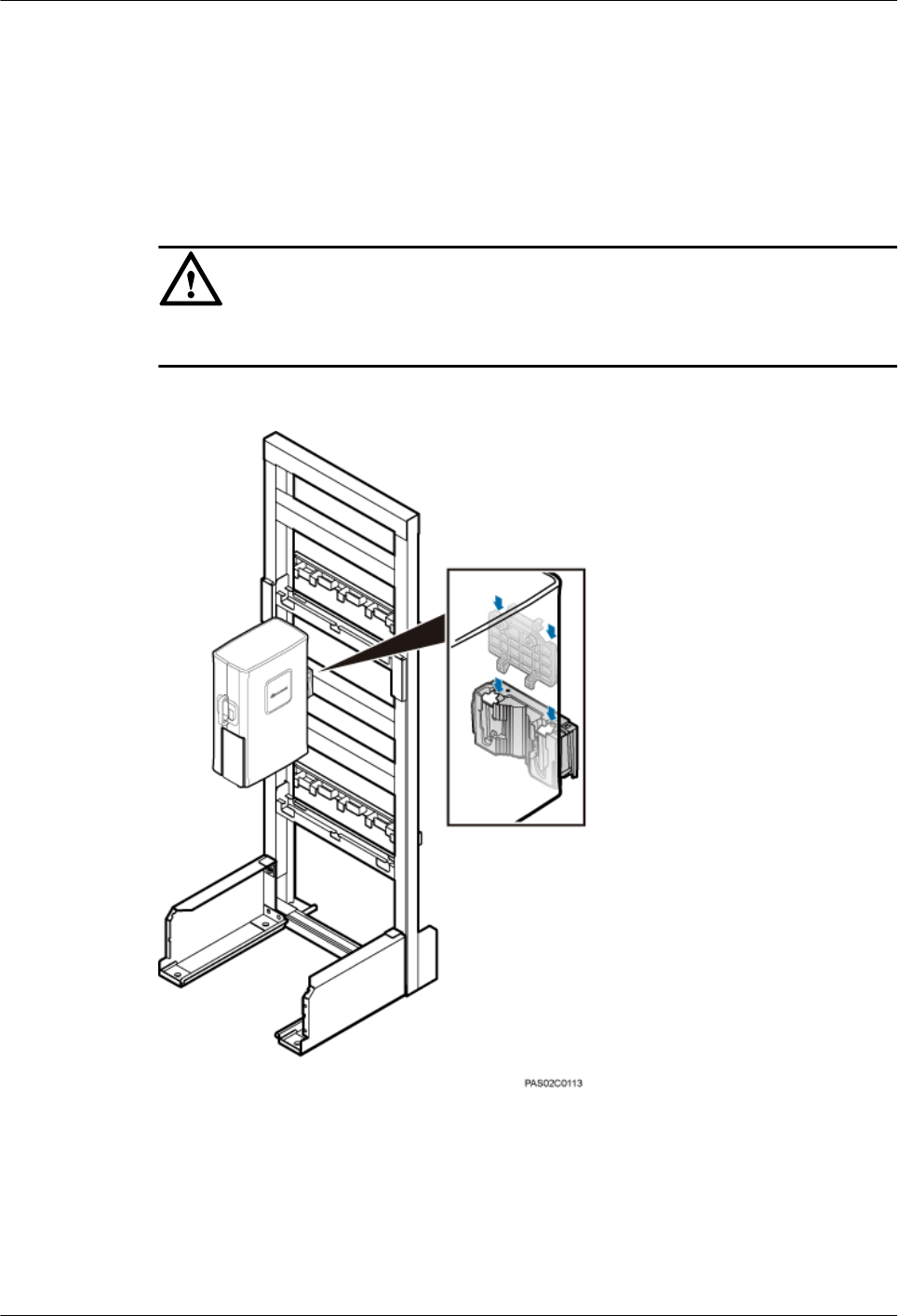
3. Optional: Install the plastic screws onto the rear of the RRU, and use a torque screwdriver
to tighten the screws to 0.25 N·m (2.21 lbf·in.).
4. Install the cover plate onto the rear of the RRU.
5. Install the attachment plate onto one side of the RRU, and use a torque screwdriver to
tighten the stainless steel screws on the attachment plate to 5 N·m (44.25 lbf·in.).
Step 2 Install the RRU onto the main bracket, as shown in Figure 14-2.
NOTICE
Do not step on the IMB03 when installing an RRU.
Figure 14-2 Installing the RRU onto the main bracket
Step 3 Repeat Step 1 and Step 2 to install more RRUs, as shown in Figure 14-3.
DBS3900 (ICR)
Installation Guide 14 Installing RRUs
Issue 12 (2015-04-30) Huawei Proprietary and Confidential
Copyright © Huawei Technologies Co., Ltd.
101
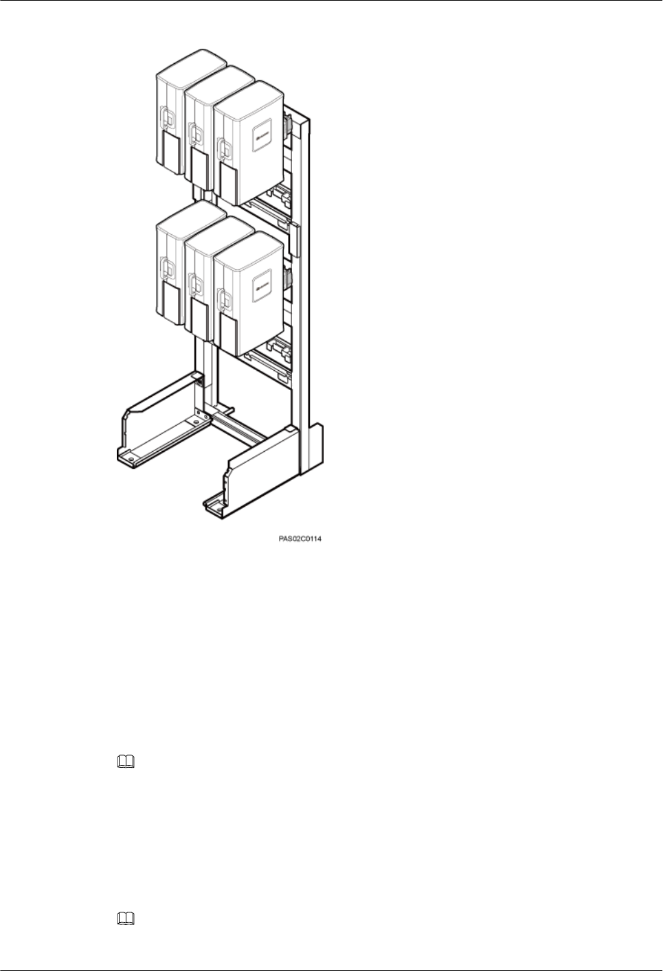
Figure 14-3 Installing multiple RRUs
----End
14.2 Installing AC RRUs
This section describes the procedure for installing AC RRUs.
Context
NOTE
lPlace a foam pad or cardboard under an RRU to protect the RRU housing from damage during the
installation.
lDo not stand the RRU upright because the RF ports cannot support the weight of the RRU.
Procedure
Step 1 Install the AC RRU onto the main bracket, as shown in Figure 14-4.
NOTE
When installing AC RRUs, install the lower RRU first and then the upper RRU.
DBS3900 (ICR)
Installation Guide 14 Installing RRUs
Issue 12 (2015-04-30) Huawei Proprietary and Confidential
Copyright © Huawei Technologies Co., Ltd.
102
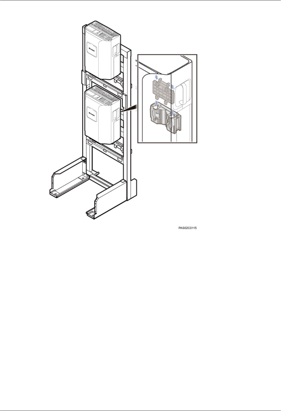
Figure 14-4 Installing AC RRUs onto the main brackets
----End
DBS3900 (ICR)
Installation Guide 14 Installing RRUs
Issue 12 (2015-04-30) Huawei Proprietary and Confidential
Copyright © Huawei Technologies Co., Ltd.
103

15 Installing Cables
About This Chapter
This chapter describes the procedure and precautions for installing and routing all ICR cables.
15.1 Cabling Requirements
Cables must be routed according to the specified cabling requirements to prevent signal
interference.
15.2 Cable Connections
This section describes the cable connections for scenarios with various power supplies.
15.3 Cable Installation Process
This section describes the process of installing ICR cables.
15.4 Cable Routes
This section describes the cable routes.
15.5 Installing PGND Cables for RRUs
This section describes the procedure for installing PGND cables for RRUs.
15.6 Installing the BBU Power Cable
This section describes the procedure for installing the BBU power cable.
15.7 Installing Input Power Cables
This section describes the procedure for installing input power cables.
15.8 (Optional) Installing the DCDU Power Cable and Monitoring Signal Cable
This section describes the procedures for installing the DCDU power cable and monitoring signal
cable for the scenarios with 220 V AC or +24 V DC power supply.
15.9 Installing RRU Power Cables
This section describes the procedures for installing RRU power cables, which feed DC power
to RRUs.
15.10 (Optional) Installing BBU Inter-connection Cable
This section describes the procedure for installing inter-BBU signal cables for a base station.
15.11 Installing Transmission Cables
This chapter describes the procedures and precautions for installing transmission cables.
DBS3900 (ICR)
Installation Guide 15 Installing Cables
Issue 12 (2015-04-30) Huawei Proprietary and Confidential
Copyright © Huawei Technologies Co., Ltd.
104

15.12 Installing CPRI Optical Cables
This section describes the procedure for installing CPRI optical cables, which transmit CPRI
signals between a BBU and RRUs.
15.13 Installing RF Jumpers
This section describes the procedure for installing RF jumpers.
15.14 Installing the GPS Clock Signal Cable
This section describes the procedure and precautions for installing a GPS clock signal cable.
DBS3900 (ICR)
Installation Guide 15 Installing Cables
Issue 12 (2015-04-30) Huawei Proprietary and Confidential
Copyright © Huawei Technologies Co., Ltd.
105

15.1 Cabling Requirements
Cables must be routed according to the specified cabling requirements to prevent signal
interference.
NOTE
If a cable listed below is not required, skip the routing requirements of the cable.
General Cabling Requirements
Requirements for Bending Radius
lThe bending radius of the 7/8'' feeder must be more than 250 mm (9.84 in.), and the bending
radius of the 5/4'' feeder must be more than 380 mm (14.96 in.).
lThe bending radius of the 1/4'' jumper must be more than 35 mm (1.38 in.). The bending
radius of the super-flexible 1/2'' jumper must be more than 50 mm (1.97 in.), and the bending
radius of the ordinary 1/2'' jumper must be more than 127 mm (5 in.).
lThe bending radius of the power cable or PGND cable must be at least three times the
diameter of the cable.
lThe bending radius of a fiber optic cable is at least 20 times the diameter of the fiber optic
cable, and the minimum bending radius of the breakout cable at each end of the fiber optic
cable is 30 mm (1.18 in.).
lThe bending radius of the E1/T1 cable must be at least three times the diameter of the cable.
lThe bending radius of the signal cable must be at least five times the diameter of the cable.
Requirements for Cable Binding
lThe same types of cable must be bound together.
lDifferent types of cable must be separately routed with the minimum spacing of 30 mm
(1.18 in.) and cannot be entangled.
lThe cables must be bound tightly and neatly. The sheaths of the cables must not be damaged.
lCable ties are installed in the same direction, and those at the same horizontal line must be
in a straight line.
lThe excess of indoor cable ties is trimmed off, and the excess of outdoor cable ties allows
about 5 mm (0.2 in.), without remaining rough edges.
lLabels or nameplates must be attached to both ends, joints, or turns of cables after they are
installed.
Security Requirements
lCables should be placed away from sharp objects or wall burrs. If these positions are
inevitable, protect the cables with protection pipes.
lCables must be routed away from heat sources, or heat-insulation materials are added
between cables and heat sources.
lSufficient slack (recommended for about 0.1 m [0.33 ft]) is provided in cables at turns or
the position close to a device, facilitating cable and device maintenance.
Indoor Cabling Requirements
lCables are routed indoors through the feeder window.
DBS3900 (ICR)
Installation Guide 15 Installing Cables
Issue 12 (2015-04-30) Huawei Proprietary and Confidential
Copyright © Huawei Technologies Co., Ltd.
106

lDrip loops must be made outside the feeder window, and the requirements for the minimum
bending radius are met.
lWhen cables are routed indoors, engineers are required indoors for cooperation.
lThe feeder window must be waterproofed.
Outdoor Cabling Requirements
lCables routed outdoors must be led through a pipe when they may be damaged.
lAC power cables, transmission cables, and cables buried in the ground must be protected.
lIf cables at the cabinet bottom need to be routed through a pipe along the ground, lead the
pipe into the cabinet base for about 30 mm (1.18 in.) to 50 mm (1.97 in.), not into the
cabinet. Block the pipe with waterproof tape or silicon gel, and secure the pipe to the cable
hole at the cabinet bottom with metal piece.
lIf cables at the cabinet bottom need to be routed through a pipe along the metal cable trough,
do not lead the pipe into the cabinet base. The cable trough must be sealed and routed
through the cable hole at the cabinet bottom.
lWhen routing RRU cables, ensure that the highest positions of the routes of all RRU cables
(except RF cables and AISG cables) must be lower than the bottom of the RRU.
lCables are secured with cable clips.
lCables are routed neatly along the specified cabling direction and secured with cable clips.
lThe positions for cable clips are determined onsite. For example, the cable clips for the
7/8" feeder are installed at the spacing of 1.5 m (4.92 ft) to 2 m (6.56 ft) in the same direction,
and the cable clips for the power cables are installed at the spacing of 1.5 m (4.92 ft) to 2
m (6.56 ft) in the same direction.
lCable clips must be vertical with cables, and the cables in a cable clip must be parallel.
lAfter routing cables neatly and correctly, tighten the screws on cable clips.
Secure cables on the cable tray, as shown in Figure 15-1.
DBS3900 (ICR)
Installation Guide 15 Installing Cables
Issue 12 (2015-04-30) Huawei Proprietary and Confidential
Copyright © Huawei Technologies Co., Ltd.
107
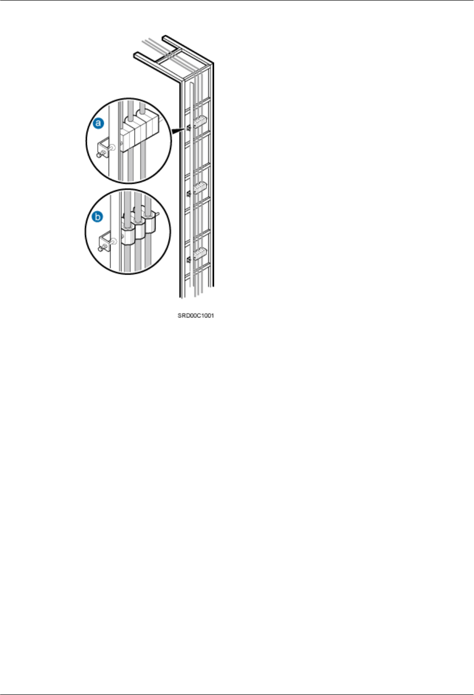
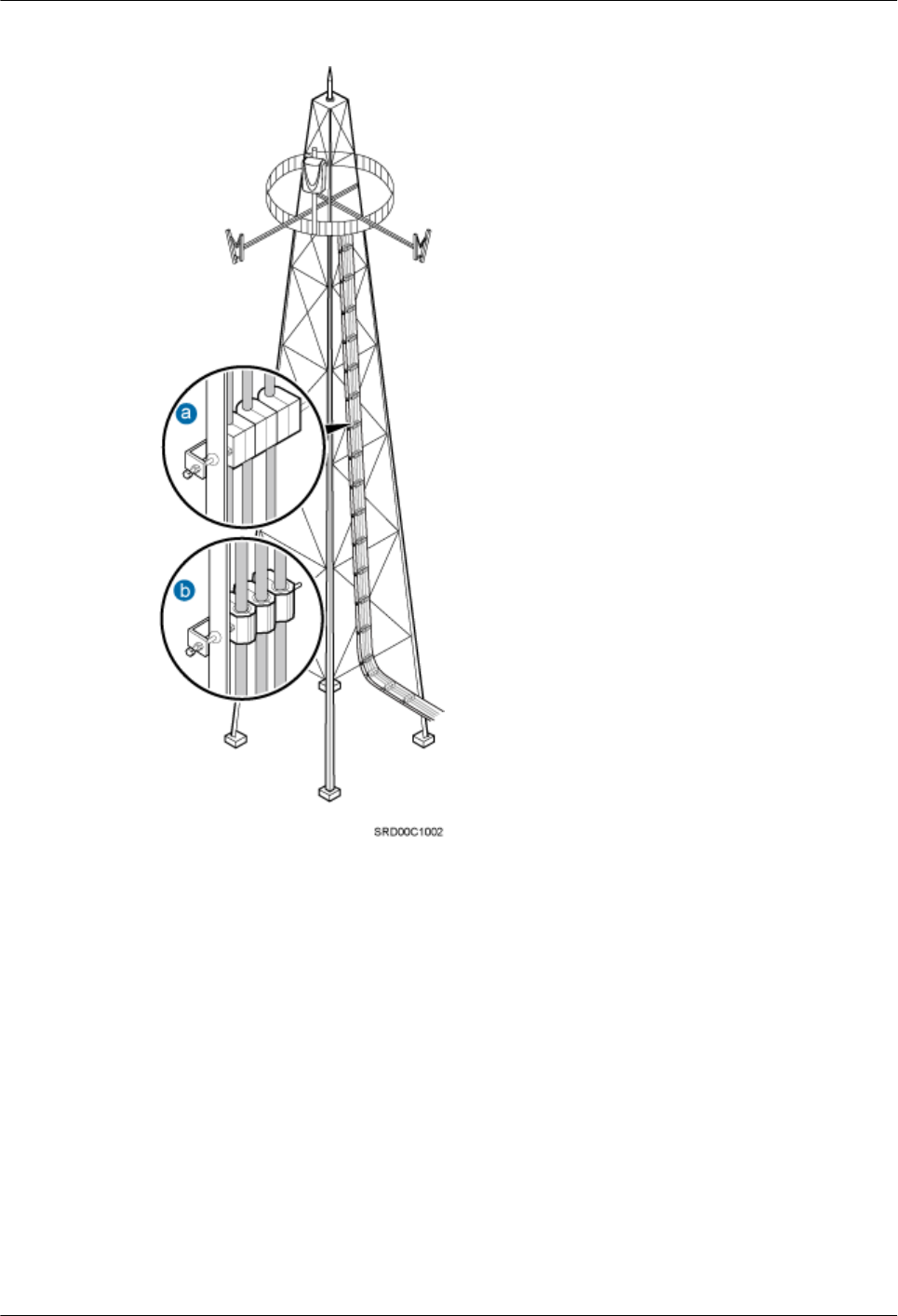
Figure 15-2 Securing cables on the tower
Special Cabling Requirements
Cabling Requirements for Power Cables
lPower cables must be installed in the position specified in engineering design documents.
lIf the length of power cables is insufficient, replace the cables rather than adding connectors
or soldering joints to lengthen the cables.
lCables must be routed by only qualified and trained personnel before all preparations are
made.
lCables are routed in an untangled and orderly fashion.
lIf DC power cables need to be routed on the tower platform, lay out the cables on the
guardrail with the shortest distance and route the cables along the guardrail.
DBS3900 (ICR)
Installation Guide 15 Installing Cables
Issue 12 (2015-04-30) Huawei Proprietary and Confidential
Copyright © Huawei Technologies Co., Ltd.
109
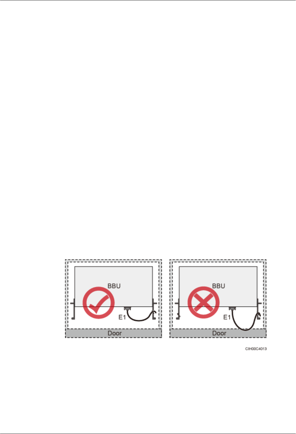
lIf DC power cables need to be routed close to a device on the tower, secure the cables to
the guardrail or pole with cable clips. The device cannot be far away from the position for
securing the cables.
Cabling Requirements for PGND Cables
lPGND cables for the base station must be connected to the same ground bar.
lPGND cables must be buried in the ground or routed indoors. They should not be routed
overhead before they are led into the equipment room.
lThe exterior of the coaxial wire and the shield layer of the shielded cable must have proper
electrical contact with the metal surface of the equipment to which they are connected.
lPGND cables and signal cables must be installed in an untangled and orderly fashion. A
certain distance must be reserved between them to prevent interference from each other.
lFuses or switches must not be installed on the PGND cables.
lOther devices must not be used for electrical connections of the PGND cables.
lAll the metal parts in the housing of the equipment must be reliably connected to the ground
terminal.
Cabling Requirements for E1 Cables
lE1 cables must not cross power cables, PGND cables, or RF cables when routed. If
transmission cables are routed with power cables, PGND cables, or RF cables in parallel,
the spacing between them must be greater than 30 mm (1.18 in.).
lE1 cables are routed straightly and bound neatly with cable ties.
lSufficient slack is provided in E1 cables at turns.
lE1 cables cannot be squeezed by the cabinet door when routed through the cabinet, as
shown in Figure 15-3.
Figure 15-3 E1 cables routed through the cabinet
Cabling Requirements for Fiber Optic Cables
lFiber optic cables must be routed by at least three qualified and trained personnel before
all preparations are made.
lFiber optic cables are used within the temperature range of -40°C to 60°C. If the current
temperature is out of the range, make protection measures or route the cables again.
DBS3900 (ICR)
Installation Guide 15 Installing Cables
Issue 12 (2015-04-30) Huawei Proprietary and Confidential
Copyright © Huawei Technologies Co., Ltd.
110
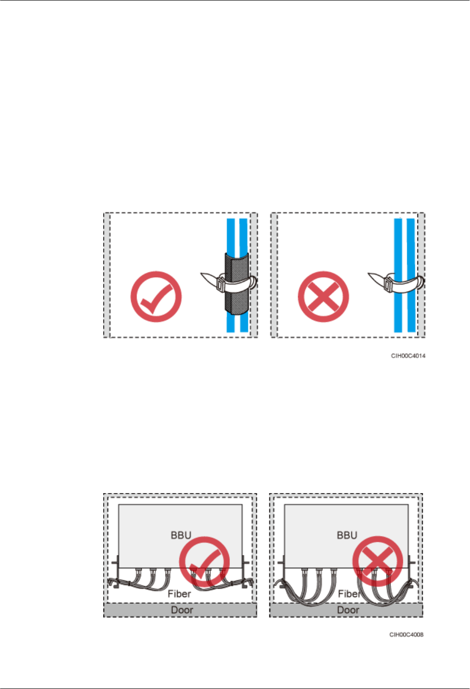
lCables are routed in an untangled and orderly fashion.
lDo not bind fiber optic cables at turns.
lDo not stretch, step on, or place heavy objects on fiber optic cables. Keep the cables away
from sharp objects.
lWhen fiber optic cables are routed, the excess of the cables must be coiled around special
devices, such as a fiber coiler.
lAn unarmored fiber optic cable must be bound using binding straps. If a fiber optic patch
cord needs to be secured in a cabinet or a piece of equipment, use binding straps to bind it
and then use cable ties to secure the binding straps to the cabinet or equipment. Ensure that
the fiber optic cables can flexibly move in the cable ties. Do not bend the fiber optic cables
sharply. The following figure shows how to bind the fiber optic cables correctly.
Figure 15-4 Binding fiber optic cables
lWhen coiling fiber optic cables, apply even strength. Do not bend the cables with force.
lVacant optical connectors must be covered with dustproof caps.
lFiber optic cables cannot be squeezed by the cabinet door when routed through the cabinet,
as shown in Figure 15-5, Figure 15-6 and Figure 15-7.
Figure 15-5 CPRI fiber optic cables routed through the cabinet (1)
DBS3900 (ICR)
Installation Guide 15 Installing Cables
Issue 12 (2015-04-30) Huawei Proprietary and Confidential
Copyright © Huawei Technologies Co., Ltd.
111
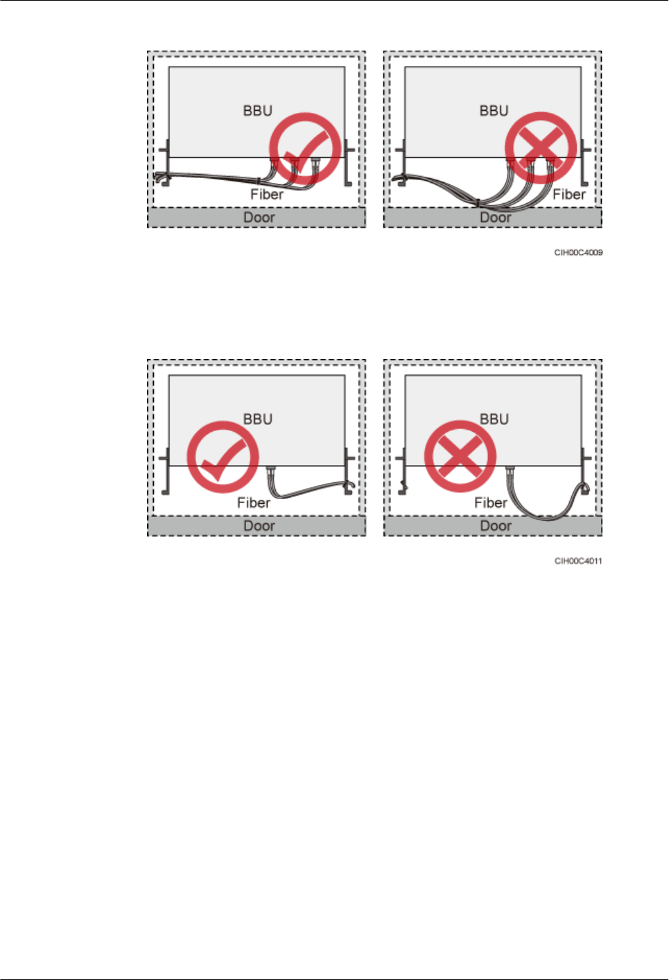
Figure 15-6 CPRI fiber optic cables routed through the cabinet (2)
Figure 15-7 FE/GE cables routed through the cabinet
lIf fiber optic cables need to be routed on the tower platform, lay out the cables on the
guardrail with the shortest distance and route the cables along the guardrail.
lIf fiber optic cables need to be routed close to a device on the tower, secure the cables to
the guardrail or pole with cable clips. The device cannot be far away from the position for
securing the cables.
lIf the fiber optic cables close to a device are too long, coil the excess of the cables and
secure them on the tower.
15.2 Cable Connections
This section describes the cable connections for scenarios with various power supplies.
15.2.1 Cable Connections (-48 V DC)
This section describes the cable connections for the scenarios with -48 V DC power supply.
DBS3900 (ICR)
Installation Guide 15 Installing Cables
Issue 12 (2015-04-30) Huawei Proprietary and Confidential
Copyright © Huawei Technologies Co., Ltd.
112
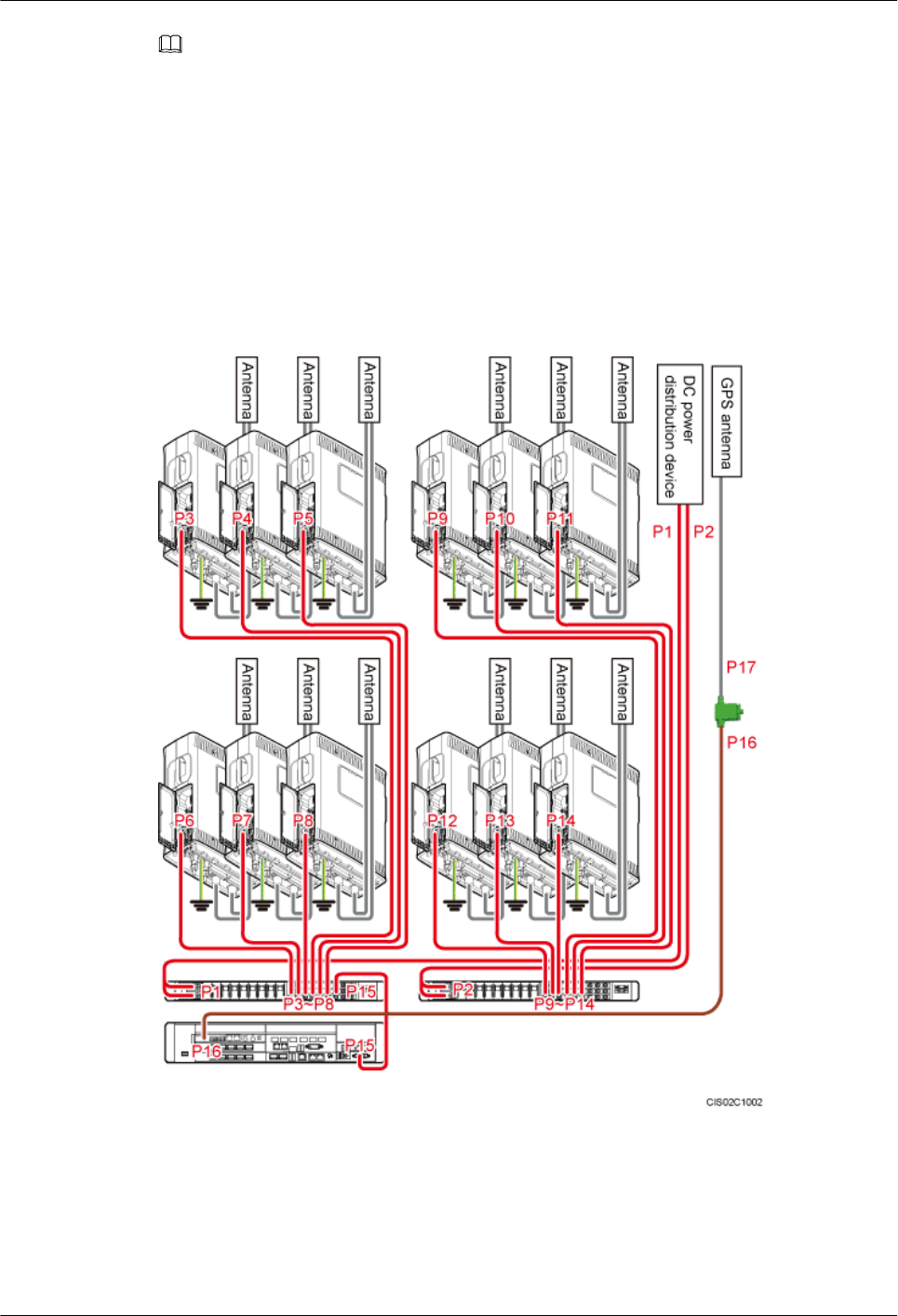
NOTE
lCable connections for the scenario with the DCDU-11B installed are the same as those for the scenario
with the DCDU-03B installed. This section uses the cable connections for the latter scenario as an
example.
lFor the connections of CPRI optical cables, see section "CPRI Cable Connections" in the BBU3900
Hardware Description.
lFor the connections of transmission cables, see section "Transmission Cable Connections" in the
BBU3900 Hardware Description.
Figure 15-8 shows and Table 15-1 lists the cable connections for a single- or dual-mode base
station supplied with -48 V DC power.
Figure 15-8 Cable connections for a single- or dual-mode base station
DBS3900 (ICR)
Installation Guide 15 Installing Cables
Issue 12 (2015-04-30) Huawei Proprietary and Confidential
Copyright © Huawei Technologies Co., Ltd.
113

Table 15-1 Cable description
No. Cable One End One End
Connecto
r
Installation
Position
Connector Installation
Position
P1 and P2 External
input power
cable
OT
terminal
RTN(+) and
NEG(-)
terminals on
the DCDU
- External power
equipment
P3 to P14 RRU power
cable
OT
terminal
LOAD0 to
LOAD5
terminals on
the DCDU
Depending
on the RRU
model
DC power supply
port on the RRU
P15 BBU power
cable
OT
terminal
LOAD6
terminal on the
DCDU
3V3 power
connector
PWR port on the
UPEU
P16 GPS clock
signal cable
SMA male
connector
GPS port on
the USCU in
the BBU
Type N
female
connector
Protect port on the
GPS surge
protector
P17 GPS jumper Type N
male
connector
Surge port on
the GPS surge
protector
Type N
male
connector
GPS antenna
Figure 15-9 shows and Table 15-2 lists the cable connections for a triple-mode base station
supplied with -48 V DC power.
DBS3900 (ICR)
Installation Guide 15 Installing Cables
Issue 12 (2015-04-30) Huawei Proprietary and Confidential
Copyright © Huawei Technologies Co., Ltd.
114
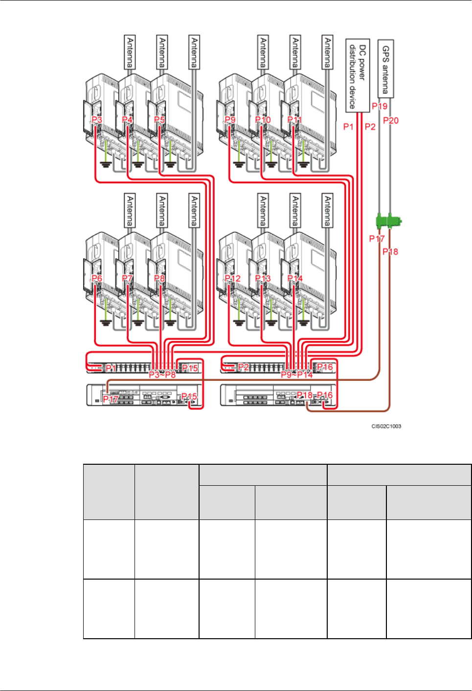
Figure 15-9 Cable connections for a triple-mode base station
Table 15-2 Cable description
No. Cable One End One End
Connecto
r
Installation
Position
Connector Installation
Position
P1 and P2 External
input power
cable
OT
terminal
RTN(+) and
NEG(-)
terminals on
the DCDU
- External power
equipment
P3 to P14 RRU power
cable
OT
terminal
LOAD0 to
LOAD5
terminals on
the DCDU
Depending
on the RRU
model
DC power supply
port on the RRU
DBS3900 (ICR)
Installation Guide 15 Installing Cables
Issue 12 (2015-04-30) Huawei Proprietary and Confidential
Copyright © Huawei Technologies Co., Ltd.
115

No. Cable One End One End
Connecto
r
Installation
Position
Connector Installation
Position
P15 and
P16
BBU power
cable
OT
terminal
LOAD6
terminal on the
DCDU
3V3 power
connector
PWR port on the
UPEU
P17 and
P18
GPS clock
signal cable
SMA male
connector
GPS port on
the USCU or
LMPT in the
BBU
Type N
female
connector
Protect port on the
GPS surge
protector
P19 and
P20
GPS jumper Type N
male
connector
Surge port on
the GPS surge
protector
Type N
male
connector
GPS antenna
15.2.2 Cable Connections (220 V AC)
This section describes the cable connections for the scenarios with 220 V AC power supply.
NOTE
lCable connections for the scenario with the DCDU-11B installed are the same as those for the scenario
with the DCDU-03B installed. This section uses the cable connections for the latter scenario as an
example.
lRRU cable connections for the scenario with 220 V AC power supply are the same as those for the
scenario with -48 V DC power supply, which is described in 15.2.1 Cable Connections (-48 V DC).
Figure 15-10 shows and Table 15-3 lists the cable connections for a base station supplied with
220 V AC power.
DBS3900 (ICR)
Installation Guide 15 Installing Cables
Issue 12 (2015-04-30) Huawei Proprietary and Confidential
Copyright © Huawei Technologies Co., Ltd.
116
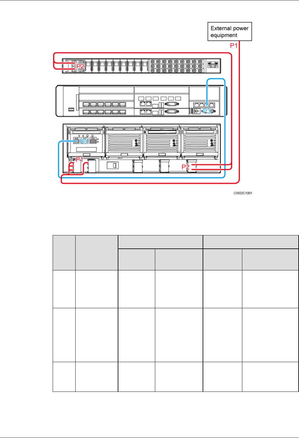
Figure 15-10 Cable connections
Table 15-3 Cable description
No. Cable One End One End
Connecto
r
Installation
Position
Connector Installation
Position
P1 External
input power
cable
OT
terminal
Power input
wiring terminal
for the AC/DC
power device
- External power
equipment
P2 DCDU power
cable
OT
terminal
RTN(+) and
NEG(-)
terminals on the
DCDU
OT terminal RTN(+) and
LOAD1(-) or
LOAD2(-)
terminals on the
AC/DC power
device
P3 PMU
monitoring
signal cable
RJ45
connector
RS232/RS485
port on the
PMU
RJ45
connector
MON1 port on the
UPEU
DBS3900 (ICR)
Installation Guide 15 Installing Cables
Issue 12 (2015-04-30) Huawei Proprietary and Confidential
Copyright © Huawei Technologies Co., Ltd.
117
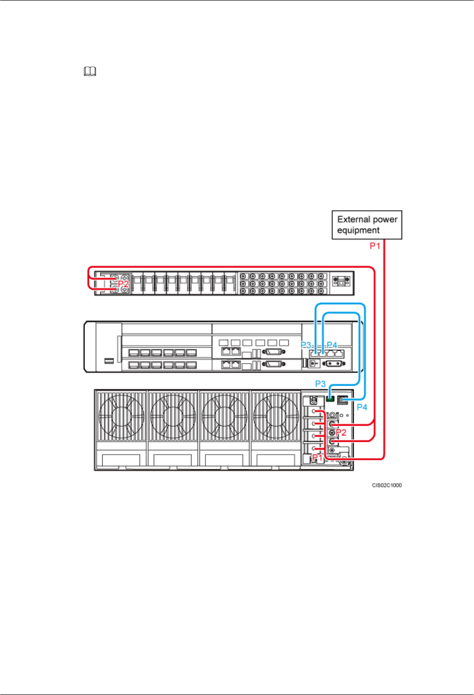
15.2.3 Cable Connections (+24 V DC)
This section describes the cable connections for the scenarios with +24 V DC power supply.
NOTE
lCable connections for the scenario with the DCDU-11B installed are the same as those for the scenario
with the DCDU-03B installed. This section uses the cable connections for the latter scenario as an
example.
lRRU cable connections for the scenario with +24 V DC power supply are the same as those for the
scenario with -48 V DC power supply, which is described in 15.2.1 Cable Connections (-48 V DC).
Figure 15-11 shows and Table 15-4 lists the cable connections for a base station supplied with
+24 V DC power.
Figure 15-11 Cable connections
DBS3900 (ICR)
Installation Guide 15 Installing Cables
Issue 12 (2015-04-30) Huawei Proprietary and Confidential
Copyright © Huawei Technologies Co., Ltd.
118

Table 15-4 Cable description
No. Cable One End One End
Connecto
r
Installation
Position
Connector Installation
Position
P1 External
input power
cable
OT
terminal
Power input
wiring
terminal for
the DC/DC
power device
- External power
equipment
P2 DCDU
power cable
OT
terminal
RTN(+) and
NEG(-)
terminals on
the DCDU
OT
terminal
RTN(+) and
LOAD(-)
terminals on the
DC/DC power
device
P3 PSU in-
position
signal cable
RJ45
connector
PRESENT
port on the DC/
DC power
device
RJ45
connector
EXT-ALM1 port
on the UPEU
P4 PSU
monitoring
signal cable
Cord end
terminal
ALM port on
the DC/DC
power device
RJ45
connector
EXT-ALM0 port
on the UPEU
15.3 Cable Installation Process
This section describes the process of installing ICR cables.
Cable Installation Process
Figure 15-12 shows the cable installation process.
DBS3900 (ICR)
Installation Guide 15 Installing Cables
Issue 12 (2015-04-30) Huawei Proprietary and Confidential
Copyright © Huawei Technologies Co., Ltd.
119

Figure 15-12 Cable installation process
15.4 Cable Routes
This section describes the cable routes.
Figure 15-13 shows the planform of the cable tray. By studying the figure, you can know the
cable routes.
Figure 15-13 Cable routes
(1) -48 V DC or 220 V AC input
power cable
(2) Optical cables and PGND cables
for RRUs at the lower layer
(3) Feeders
(4) RRU power cables, E1/T1 cables,
and FE/GE Ethernet or optical cables
(5) +24 V DC input power cable -
DBS3900 (ICR)
Installation Guide 15 Installing Cables
Issue 12 (2015-04-30) Huawei Proprietary and Confidential
Copyright © Huawei Technologies Co., Ltd.
120
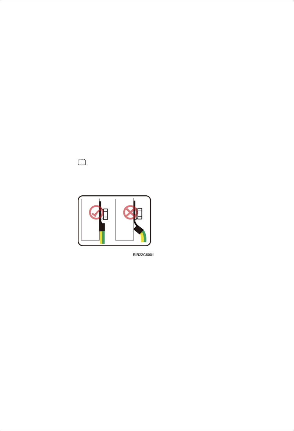
15.5 Installing PGND Cables for RRUs
This section describes the procedure for installing PGND cables for RRUs.
Context
The cross-sectional area of the PGND cable for an RRU is 16 mm2 (0.025 in.2).
Procedure
lTo install the PGND cable for a DC RRU, perform the following operations:
1. Cut the cable to a length suitable for the actual cable route.
2. Add an OT terminal to each end of the cable according to the instructions in
Assembling the OT Terminal and the Power Cable.
3. Connect one end of the PGND cable to the RRU, as shown in Figure 15-15.
NOTE
Crimp OT terminals in correct directions, as shown in Figure 15-14.
Figure 15-14 Correct direction of an OT terminal
DBS3900 (ICR)
Installation Guide 15 Installing Cables
Issue 12 (2015-04-30) Huawei Proprietary and Confidential
Copyright © Huawei Technologies Co., Ltd.
121
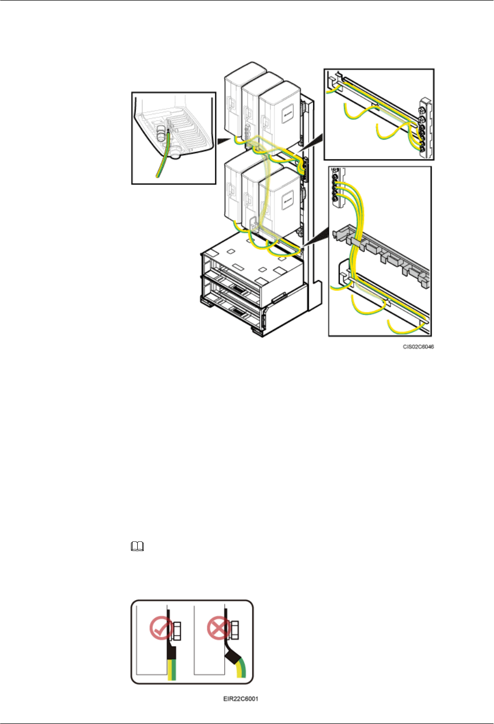
Figure 15-15 PGND cable for the DC RRU
4. Connect the other end of the PGND cable to the ground bar on the IFS06.
5. Lay out the cables according to the instructions in 15.1 Cabling Requirements, and
use cable ties to bind the cables.
6. Label the installed cables according to the instructions in Attaching a Cable-Tying
Label.
lTo install the PGND cable for an AC RRU, perform the following operations:
1. Cut the cable to a length suitable for the actual cable route.
2. Add an OT terminal to each end of the cable according to the instructions in
Assembling the OT Terminal and the Power Cable.
3. Connect one end of the PGND cable to the RRU, as shown in Figure 15-17.
NOTE
Crimp OT terminals in correct directions, as shown in Figure 15-16.
Figure 15-16 Correct direction of an OT terminal
DBS3900 (ICR)
Installation Guide 15 Installing Cables
Issue 12 (2015-04-30) Huawei Proprietary and Confidential
Copyright © Huawei Technologies Co., Ltd.
122
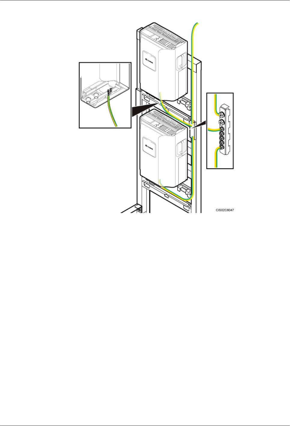
Figure 15-17 PGND cable for the AC RRU
4. Connect the other end of the PGND cable to the ground bar on the IFS06.
5. Lay out the cables according to the instructions in 15.1 Cabling Requirements, and
use cable ties to bind the cables.
6. Label the installed cables according to the instructions in Attaching a Cable-Tying
Label.
----End
15.6 Installing the BBU Power Cable
This section describes the procedure for installing the BBU power cable.
Context
Table 15-5 lists the specifications of a BBU power cable.
DBS3900 (ICR)
Installation Guide 15 Installing Cables
Issue 12 (2015-04-30) Huawei Proprietary and Confidential
Copyright © Huawei Technologies Co., Ltd.
123
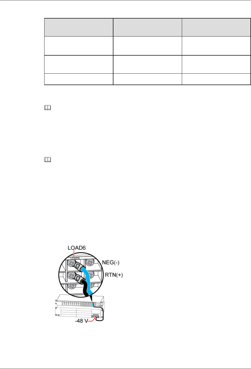
Table 15-5 Specifications of a BBU power cable
Power Device Connector on the BBU
Side
Connector on the Power
Device Side
DCDU-03B 3V3 connector OT terminal (M4) bent by
90o
DCDU-11B 3V3 connector Tool-less female connector
(pressfit type)
DCDU-12B 3V3 connector EPC4 Connector
NOTE
This section describes how to install the BBU power cable when the DCDU-03B is used as the power device.
Procedure
Step 1 Add a connector to the BBU power cable on the power device side according to the instructions
in Assembling the OT Terminal and the Power Cable.
NOTE
A 3V3 connector has been added to one end of the BBU power cable before delivery. Another connector
must be added to the other end of the cable onsite.
Step 2 Install the BBU power cable, as shown in Figure 15-18.
1. Connect the 3V3 connector at one end of the BBU power cable to the PWR port on the
UPEU in the BBU. Then tighten the screws on the connector to 0.25 N·m (2.21 lbf·in.).
2. Connect the blue and black OT terminals at the other end of the BBU power cable to the
NEG(-) and RTN(+) terminals, respectively, in the LOAD6 column on the DCDU-03B.
Then tighten the screws on the connector to 1.2 N·m (10.61 lbf·in.).
Figure 15-18 Installing the BBU power cable
Step 3 Lay out the cable according to the instructions in 15.1 Cabling Requirements, and use cable
ties to bind the cable.
DBS3900 (ICR)
Installation Guide 15 Installing Cables
Issue 12 (2015-04-30) Huawei Proprietary and Confidential
Copyright © Huawei Technologies Co., Ltd.
124

Step 4 Label the installed cable according to the instructions in Attaching a Cable-Tying Label.
----End
15.7 Installing Input Power Cables
This section describes the procedure for installing input power cables.
Context
An ICR supports power inputs of -48 V DC, +24 V DC, and 220 V AC.
The input power cables for an ICR must be prepared onsite. Table 15-6 lists the specifications
of input power cables.
Table 15-6 Specifications of input power cables
Cable Connector at
One End
Connector at the
Other End
Cross-Sectional
Area
-48 V DC input
power cable
(DCDU-03B)
OT terminal
(M6)
Depending on the
external power system
16 mm2 (0.025 in.2, a
pair)
-48 V DC input
power cable
(DCDU-11B)
OT terminal
(M6)
Depending on the
external power system
16 mm2 (0.025 in.2,
two pairs)
+24 V DC input
power cable
OT terminal
(M6)
Depending on the
external power system
25 mm2 (0.039 in.2)
220 V AC single-
phase input power
cable
OT terminal
(M6)
Depending on the
external power system
6 mm2 (0.009 in.2)
220 V AC three-
phase input power
cable
OT terminal
(M6)
Depending on the
external power system
2.5 mm2 (0.004 in.2)
Procedure
lTo install the -48 V DC input power cable, perform the following operations:
1. Cut the cable to a length suitable for the actual cable route.
2. Add an OT terminal to one end of the cable according to the instructions in Assembling
the OT Terminal and the Power Cable.
3. Connect one end of the power cable to the corresponding RTN(+) and NEG(-)
terminals on the DCDU-03B or DCDU-11B, as shown in Figure 15-19.
DBS3900 (ICR)
Installation Guide 15 Installing Cables
Issue 12 (2015-04-30) Huawei Proprietary and Confidential
Copyright © Huawei Technologies Co., Ltd.
125
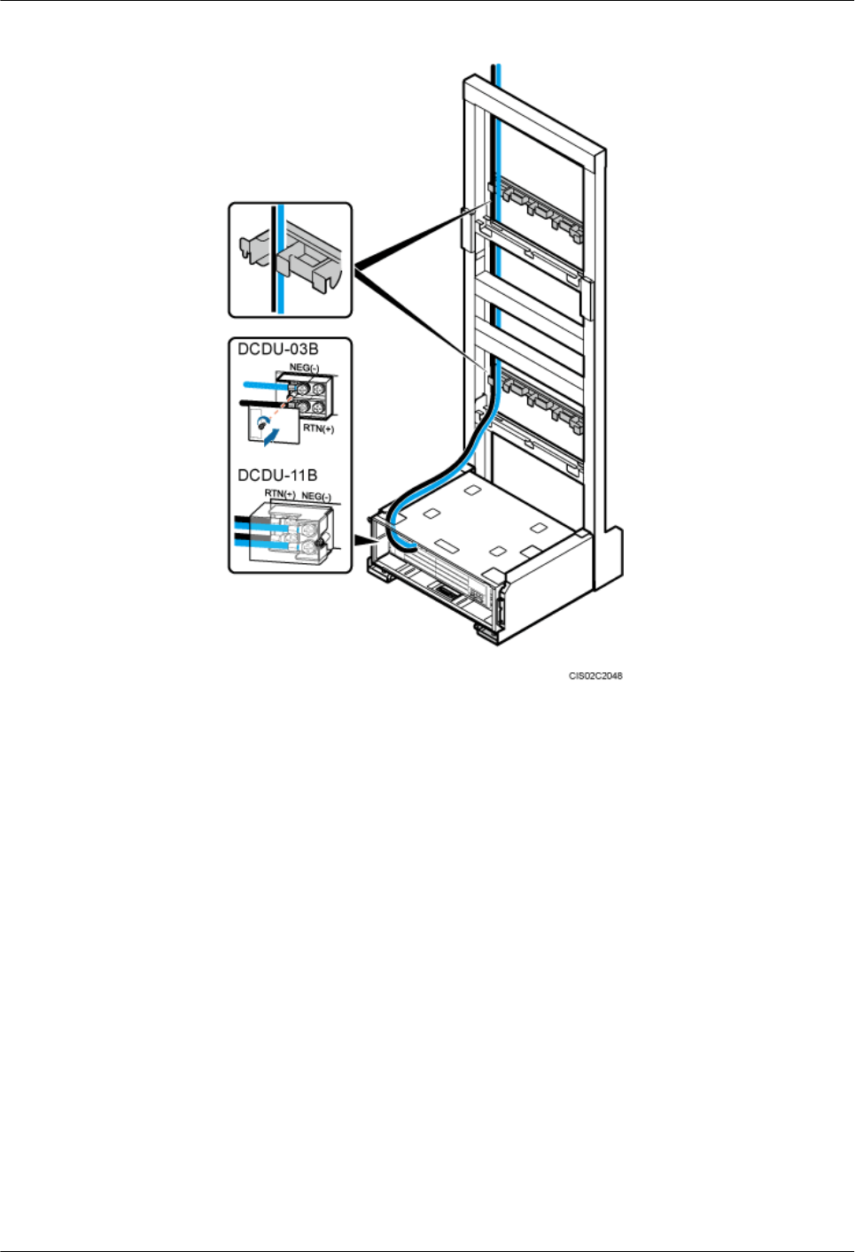
Figure 15-19 Installing the -48 V DC input power cable
4. Route the other end of the power cable along the cable trough at the rear left of the
IFS06. Then connect the power cable to the external power system, as shown in Figure
15-19.
5. Lay out the cable according to the instructions in 15.1 Cabling Requirements, and
use cable ties to bind the cable.
6. Label the installed cable according to the instructions in Attaching a Cable-Tying
Label.
lTo install the +24 V DC input power cable, perform the following operations:
1. Cut the cable to a length suitable for the actual cable route.
2. Add an OT terminal to one end of the cable according to the instructions in Assembling
the OT Terminal and the Power Cable.
3. Connect one end of the power cable to the wiring terminals marked + and - on the
wiring unit of the DC/DC power system, as shown in Figure 15-20.
DBS3900 (ICR)
Installation Guide 15 Installing Cables
Issue 12 (2015-04-30) Huawei Proprietary and Confidential
Copyright © Huawei Technologies Co., Ltd.
126
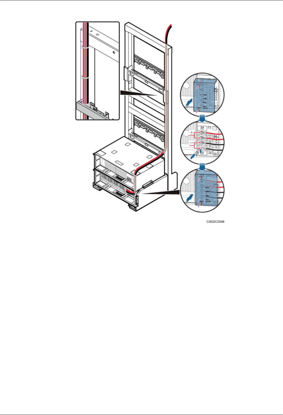
Figure 15-20 Installing the +24 V DC input power cable
4. Route the other end of the power cable along the cable trough at the rear left of the
IFS06. Then connect the power cable to the external power system, as shown in Figure
15-20.
5. Lay out the cable according to the instructions in 15.1 Cabling Requirements, and
use cable ties to bind the cable.
6. Label the installed cable according to the instructions in Attaching a Cable-Tying
Label.
lTo install the 220 V AC input power cable, perform the following operations:
1. Cut the cable to a length suitable for the actual cable route.
2. Add an OT terminal to one end of the cable according to the instructions in Assembling
the OT Terminal and the Power Cable.
3. Connect one end of the power cable to the AC INPUT port on the AC/DC power
system, as shown in Figure 15-21.
DBS3900 (ICR)
Installation Guide 15 Installing Cables
Issue 12 (2015-04-30) Huawei Proprietary and Confidential
Copyright © Huawei Technologies Co., Ltd.
127
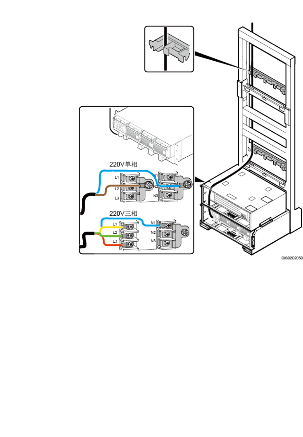
Figure 15-21 Installing the 220 V AC input power cable
4. Route the other end of the power cable along the cable trough at the rear left of the
IFS06. Then connect the power cable to the external power system, as shown in Figure
15-21.
5. Lay out the cable according to the instructions in 15.1 Cabling Requirements, and
use cable ties to bind the cable.
6. Label the installed cable according to the instructions in Attaching a Cable-Tying
Label.
----End
15.8 (Optional) Installing the DCDU Power Cable and
Monitoring Signal Cable
This section describes the procedures for installing the DCDU power cable and monitoring signal
cable for the scenarios with 220 V AC or +24 V DC power supply.
DBS3900 (ICR)
Installation Guide 15 Installing Cables
Issue 12 (2015-04-30) Huawei Proprietary and Confidential
Copyright © Huawei Technologies Co., Ltd.
128

Context
lDCDU-03B can use a pair of power cables with cross-sectional area of 16 mm2 (0.025 in.
2).
lDCDU-11B or DCDU-12B can use two pairs of power cables with cross-sectional area of
16 mm2 (0.025 in. 2).
lIn the scenarios with 220 V AC or +24 V DC power supply, a power cable between the
power system and the DCDU must be installed as well as a monitoring signal cable between
the power system and the BBU.
NOTE
In the scenarios with -48 V DC power supply, one end of the power cable is directly connected to the
DCDU and one end of the monitoring signal cable is directly connected to the BBU; the other ends of the
cables are connected to the external power system.
Procedure
lTo install the DCDU power cable and monitoring signal cable in the scenarios with +24 V
DC power supply, perform the following operations:
1. Cut the power cable to a length suitable for the actual cable route.
2. Add an OT terminal to each end of the power cable according to the instructions in
Assembling the OT Terminal and the Power Cable.
3. Connect one end of the power cable to the wiring terminals marked LOAD(-) and
RTN(+) on the wiring unit of the DC/DC power system, as shown in Figure 15-23.
In Figure 15-22, the red line is the power cable, and the blue line is the monitoring
signal cable.
DBS3900 (ICR)
Installation Guide 15 Installing Cables
Issue 12 (2015-04-30) Huawei Proprietary and Confidential
Copyright © Huawei Technologies Co., Ltd.
129
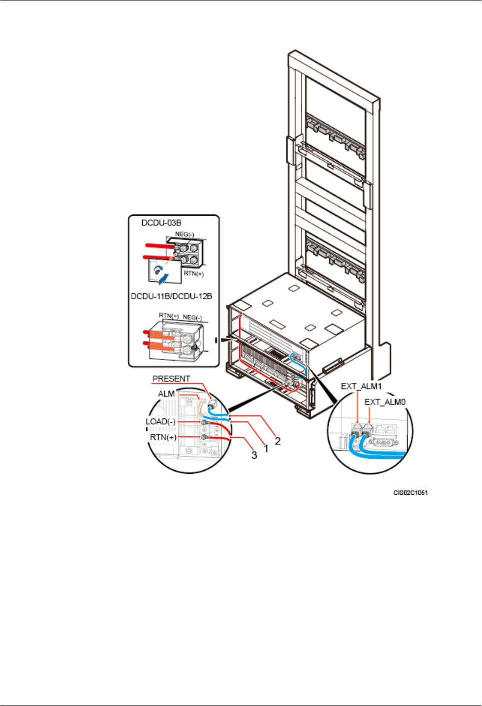
Figure 15-22 Power cable and monitoring signal cable in scenarios with +24 V DC
power supply
(1) PSU in-position signal cable (2) PSU monitoring signal cable (3) DCDU power cable
4. Connect the other end of the power cable to the wiring terminals marked NEG(-) and
RTN(+) on the DCDU.
5. Connect one end of the PSU monitoring signal cable to the EXT-ALM0 port on the
UPEU, and the other end to the ALM port on the DC/DC power system.
6. Connect one end of the PSU in-position signal cable to the EXT-ALM1 port on the
UPEU, and the other end to the PRESENT port on the DC/DC power system.
7. Lay out the cables according to the instructions in 15.1 Cabling Requirements, and
use cable ties to bind the cables.
8. Label the installed cables according to the instructions in Attaching an L-Shaped
Label.
DBS3900 (ICR)
Installation Guide 15 Installing Cables
Issue 12 (2015-04-30) Huawei Proprietary and Confidential
Copyright © Huawei Technologies Co., Ltd.
130
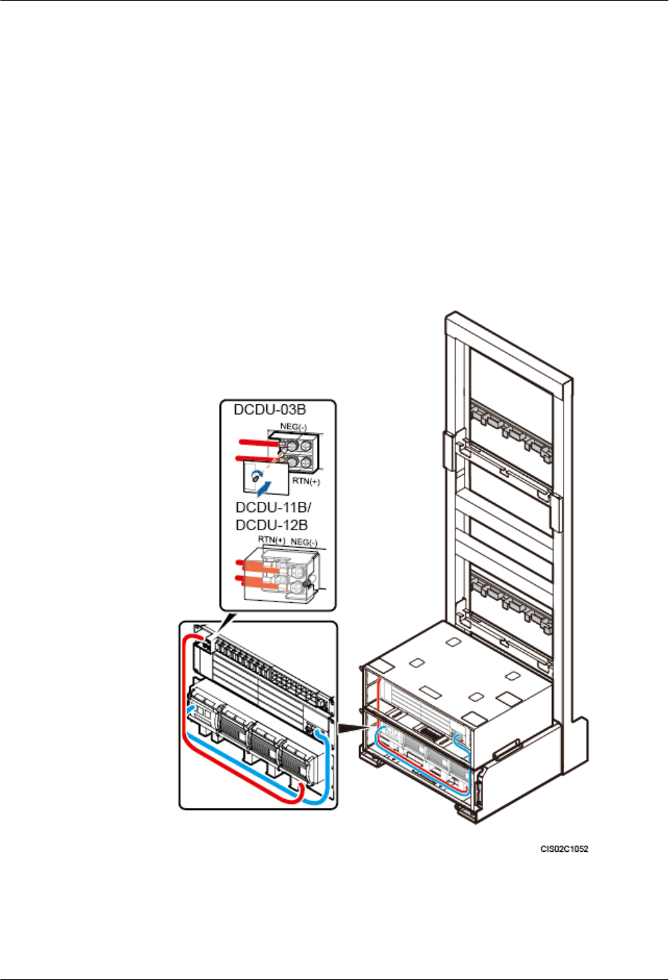
lTo install the DCDU power cable and monitoring signal cable in the scenarios with 220 V
AC power supply, perform the following operations:
1. Cut the power cable to a length suitable for the actual cable route.
2. Add an OT terminal to each end of the power cable according to the instructions in
Assembling the OT Terminal and the Power Cable.
3. Connect one end of the power cable to the wiring terminals marked LOAD1(-)/
LOAD2(-) and RTN(+) on the wiring unit of the AC/DC power system, as shown in
Figure 15-23.
In Figure 15-23, the red line is the power cable, and the blue line is the monitoring
signal cable.
Figure 15-23 DCDU power cable and monitoring signal cable in scenarios with 220
V AC power supply
4. Connect the other end of the power cable to the wiring terminals marked NEG(-) and
RTN(+) on the DCDU-03B.
5. Connect one end of the monitoring signal cable to the MON1 port on the UPEU, and
the other end to the RS232/RS485 port on the AC/DC power system.
DBS3900 (ICR)
Installation Guide 15 Installing Cables
Issue 12 (2015-04-30) Huawei Proprietary and Confidential
Copyright © Huawei Technologies Co., Ltd.
131
6. Lay out the cables according to the instructions in 15.1 Cabling Requirements, and
use cable ties to bind the cables.
7. Label the installed cables according to the instructions in Attaching an L-Shaped
Label.
----End
15.9 Installing RRU Power Cables
This section describes the procedures for installing RRU power cables, which feed DC power
to RRUs.
Context
Table 15-7 lists the specifications of RRU power cables.
Table 15-7 Specifications of RRU power cables
Cable Power
Device
Connector on the Power
Device Side
Connector on the RRU
Side
RRU power
cable
DCDU-12B EPC5 connector Depending on the RRU
model
DCDU-11B Tool-less female connector
(pressfit type)
DCDU-03B Bent OT terminal (M4)
NOTE
lColors and structures of cables vary in different regions. If cables are purchased at local markets, they
must comply with local rules and regulations.
lThe type of connector at the other end of an RRU power cable depends on the type of the RRU to which
the power cable is connected. For how to add a connector to an RRU power cable, see the related RRU
installation guide.
Procedure
lTo install the power cable for a DC RRU, perform the following operations:
1. Open the cover plate of the RRU cabling cavity.
2. Cut the cable to a length suitable for the actual cable route.
3. Add a connector to each end of the RRU power cable.
4. Route the RRU power cable from the RRU side to the power equipment side through
the feeder window. Install a ground clip near the feeder window outside the equipment
room, and connect the PGND cable on the ground clip to the external ground bar. The
installation procedure of ground clip is as follows:
a. Use a wire stripper to strip 63 mm (2.48 in.) long jacket off the power cable to
expose the shield layer.
DBS3900 (ICR)
Installation Guide 15 Installing Cables
Issue 12 (2015-04-30) Huawei Proprietary and Confidential
Copyright © Huawei Technologies Co., Ltd.
132
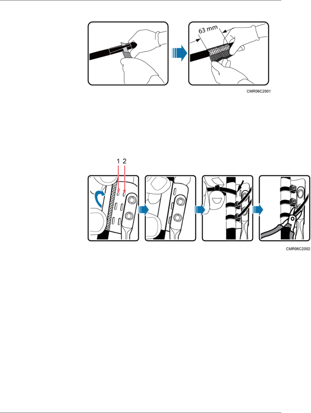
Figure 15-24 Stripping the jacket off the power cable
b. Wrap the copper sheet of the ground clip around the shield layer of the power
cable, and use cable ties to bind them tightly. Then trim off surplus part from the
heads of the cable ties without leaving any sharp edge.
Figure 15-25 Wrapping and tying the copper sheet of the ground clip
(1) Hole for a cable tie (12AWG/4 mm2 or 0.006
in.2)
(2) Hole for a cable tie (≥ 6 mm2 or 0.009
in.2)
c. Wrap three layers of waterproof tape and three layers of insulation tape around
the ground clip.
DBS3900 (ICR)
Installation Guide 15 Installing Cables
Issue 12 (2015-04-30) Huawei Proprietary and Confidential
Copyright © Huawei Technologies Co., Ltd.
133
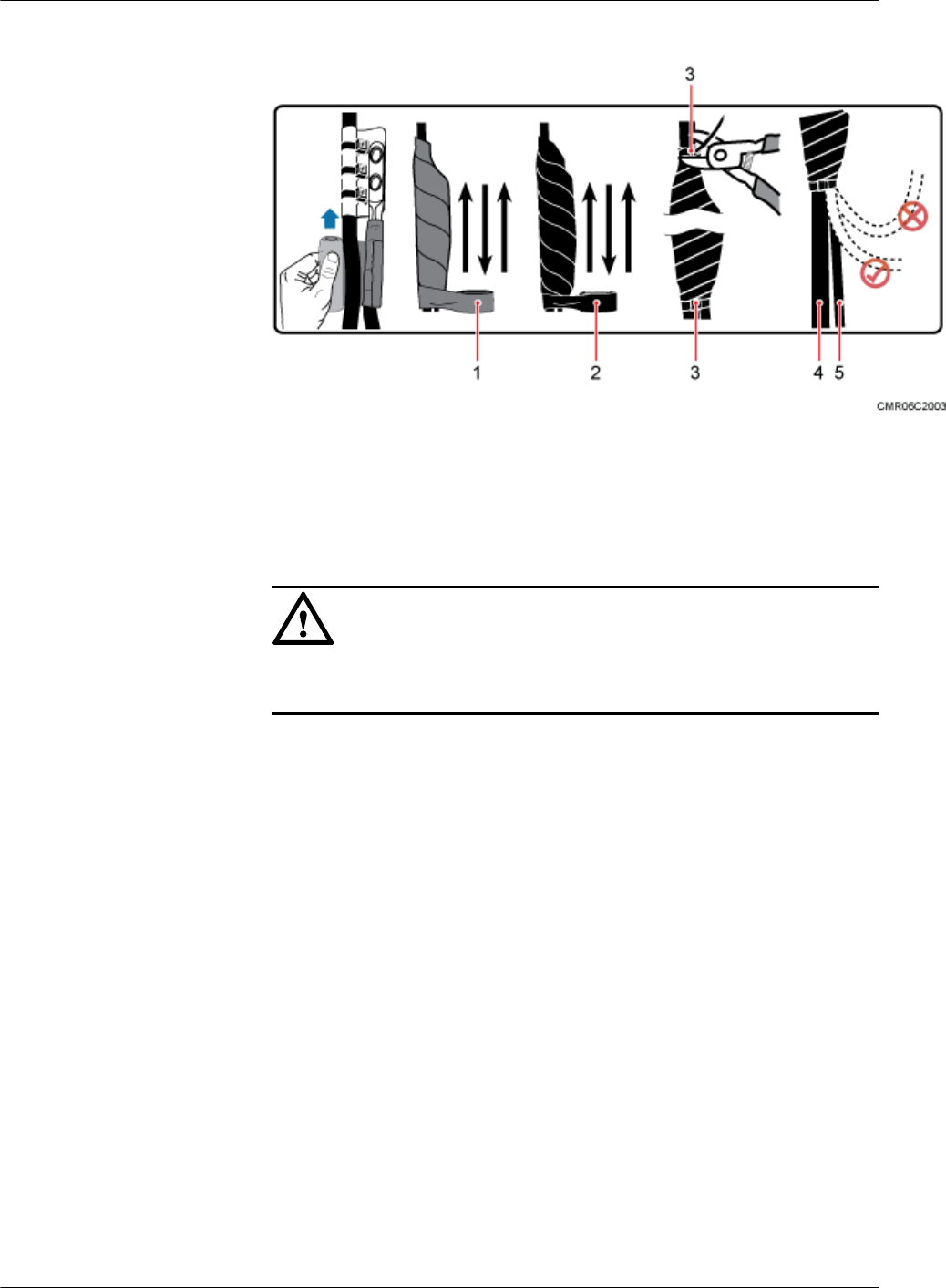
Figure 15-26 Wrapping the waterproof tape and insulation tape
(1) Waterproof tape (2) Insulation tape (3) Cable tie
(4) Power cable (5) PGND cable -
NOTICE
Trim off surplus part of the cable ties at the position 3 mm (0.12 in.) to 5 mm
(0.20 in.) away from the head of the cable tie.
5. Connect one end of the RRU power cable to the DC power port on the DC RRU, as
shown in Figure 15-27.
DBS3900 (ICR)
Installation Guide 15 Installing Cables
Issue 12 (2015-04-30) Huawei Proprietary and Confidential
Copyright © Huawei Technologies Co., Ltd.
134
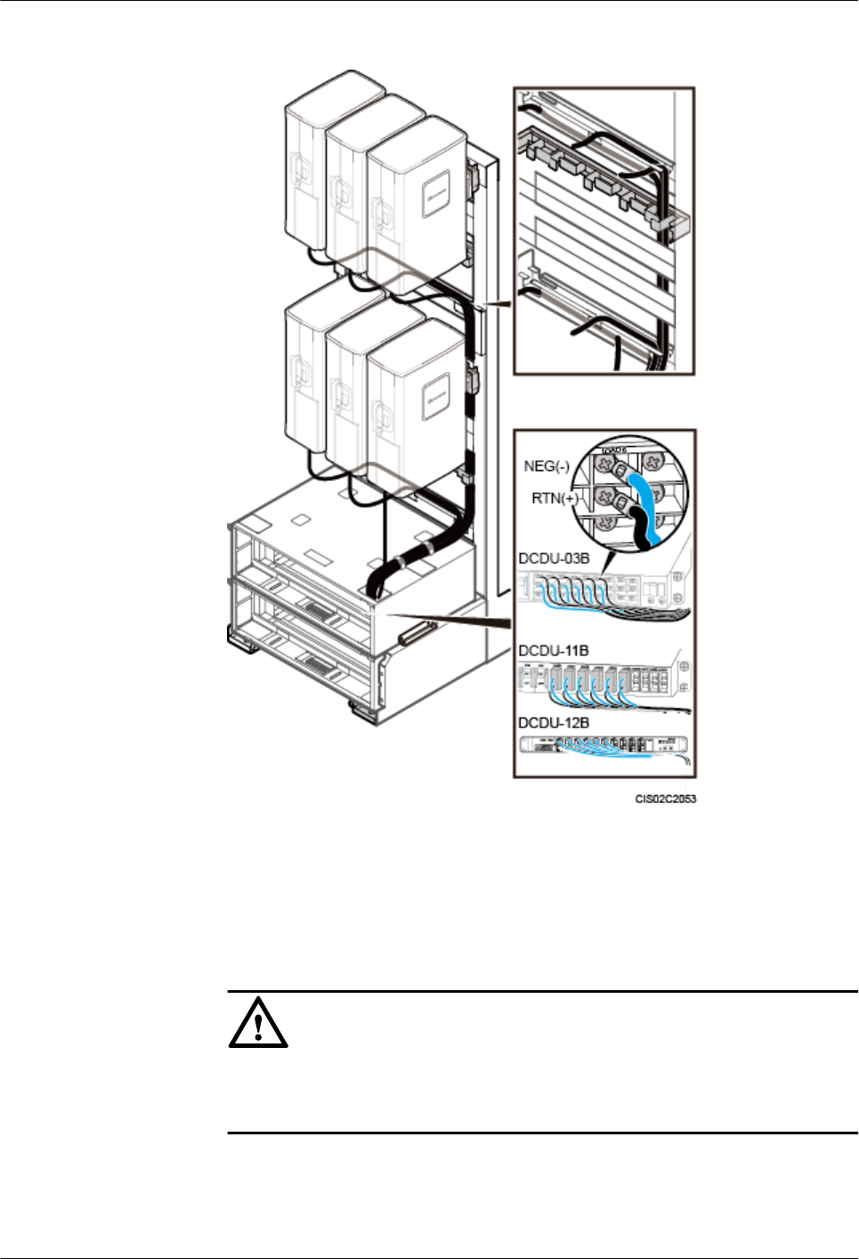
Figure 15-27 Installing the power cable for a DC RRU
6. Connect the other end of the RRU power cable to one of the LOAD0 to LOAD5 ports
on the DCDU. When the power device is DCDU-03B, then tighten the screws on the
connector to 1.2 N·m (10.61 lbf·in.).
7. Lay out the cable according to the instructions in 15.1 Cabling Requirements, and
use cable ties to bind the cable.
NOTICE
When routing the RRU power cable on the top of the IMB03, avoid obstructing the
heat dissipation holes of the IMB03.
8. Label the installed cable according to the instructions in Attaching a Cable-Tying
Label.
lTo install the power cable for an AC RRU, perform the following operations:
DBS3900 (ICR)
Installation Guide 15 Installing Cables
Issue 12 (2015-04-30) Huawei Proprietary and Confidential
Copyright © Huawei Technologies Co., Ltd.
135
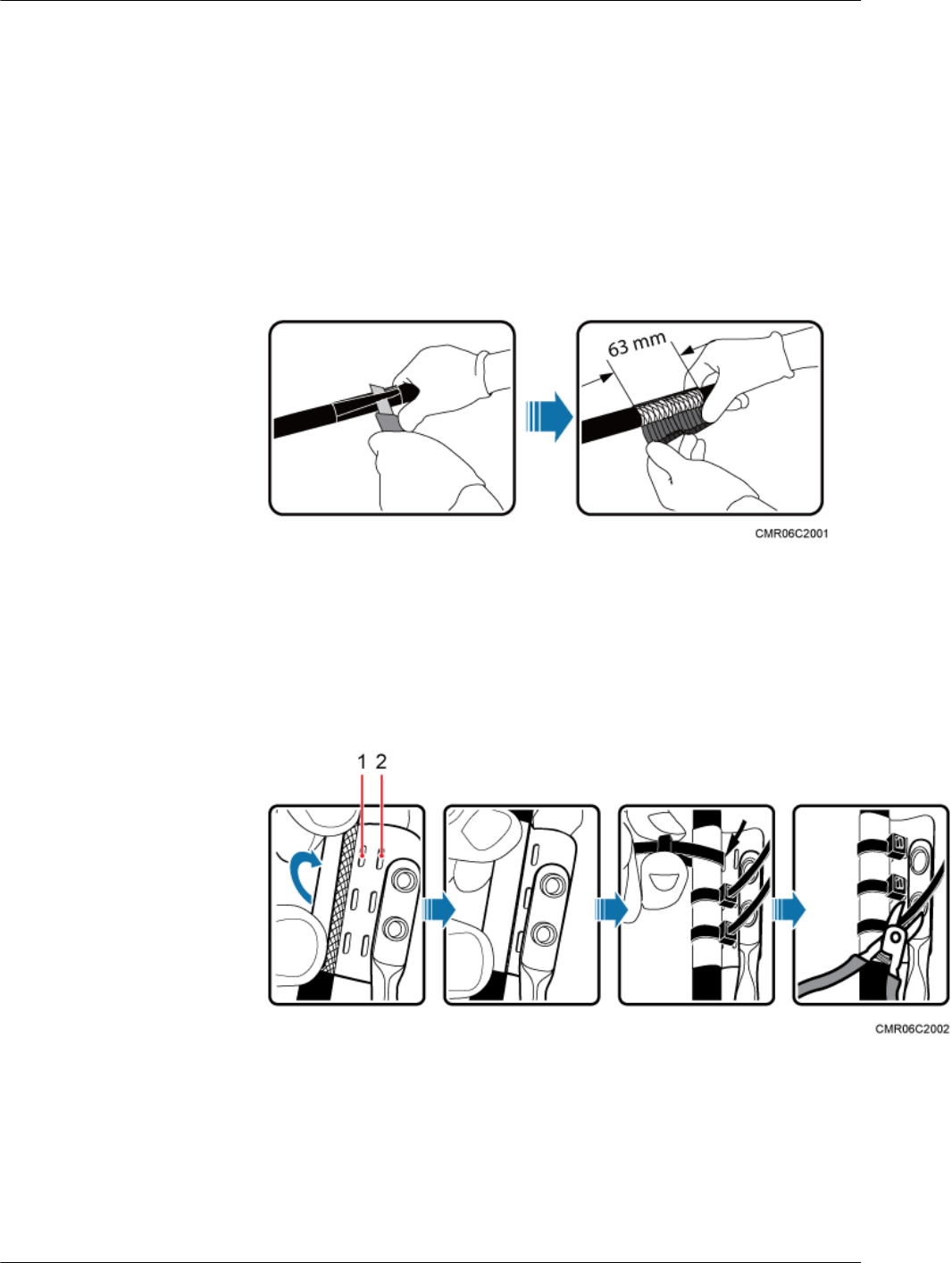
1. Cut the cable to a length suitable for the actual cable route.
2. Add a connector to each end of the RRU power cable.
3. Route the RRU power cable from the RRU side to the power equipment side through
the feeder window. Install a ground clip near the feeder window outside the equipment
room, and connect the PGND cable on the ground clip to the external ground bar. The
installation procedure of ground clip is as follows:
a. Use a wire stripper to strip 63 mm (2.48 in.) long jacket off the power cable to
expose the shield layer.
Figure 15-28 Stripping the jacket off the power cable
b. Wrap the copper sheet of the ground clip around the shield layer of the power
cable, and use cable ties to bind them tightly. Then trim off surplus part from the
heads of the cable ties without leaving any sharp edge.
Figure 15-29 Wrapping and tying the copper sheet of the ground clip
(1) Hole for a cable tie (12AWG/4 mm2 or 0.006
in.2)
(2) Hole for a cable tie (≥ 6 mm2 or 0.009
in.2)
c. Wrap three layers of waterproof tape and three layers of insulation tape around
the ground clip.
DBS3900 (ICR)
Installation Guide 15 Installing Cables
Issue 12 (2015-04-30) Huawei Proprietary and Confidential
Copyright © Huawei Technologies Co., Ltd.
136

Figure 15-30 Wrapping the waterproof tape and insulation tape
(1) Waterproof tape (2) Insulation tape (3) Cable tie
(4) Power cable (5) PGND cable -
NOTICE
Trim off surplus part of the cable ties at the position 3 mm (0.12 in.) to 5 mm
(0.20 in.) away from the head of the cable tie.
4. Connect one end of the RRU power cable to the AC power port at the bottom of the
AC RRU, as shown in Figure 15-31.
DBS3900 (ICR)
Installation Guide 15 Installing Cables
Issue 12 (2015-04-30) Huawei Proprietary and Confidential
Copyright © Huawei Technologies Co., Ltd.
137
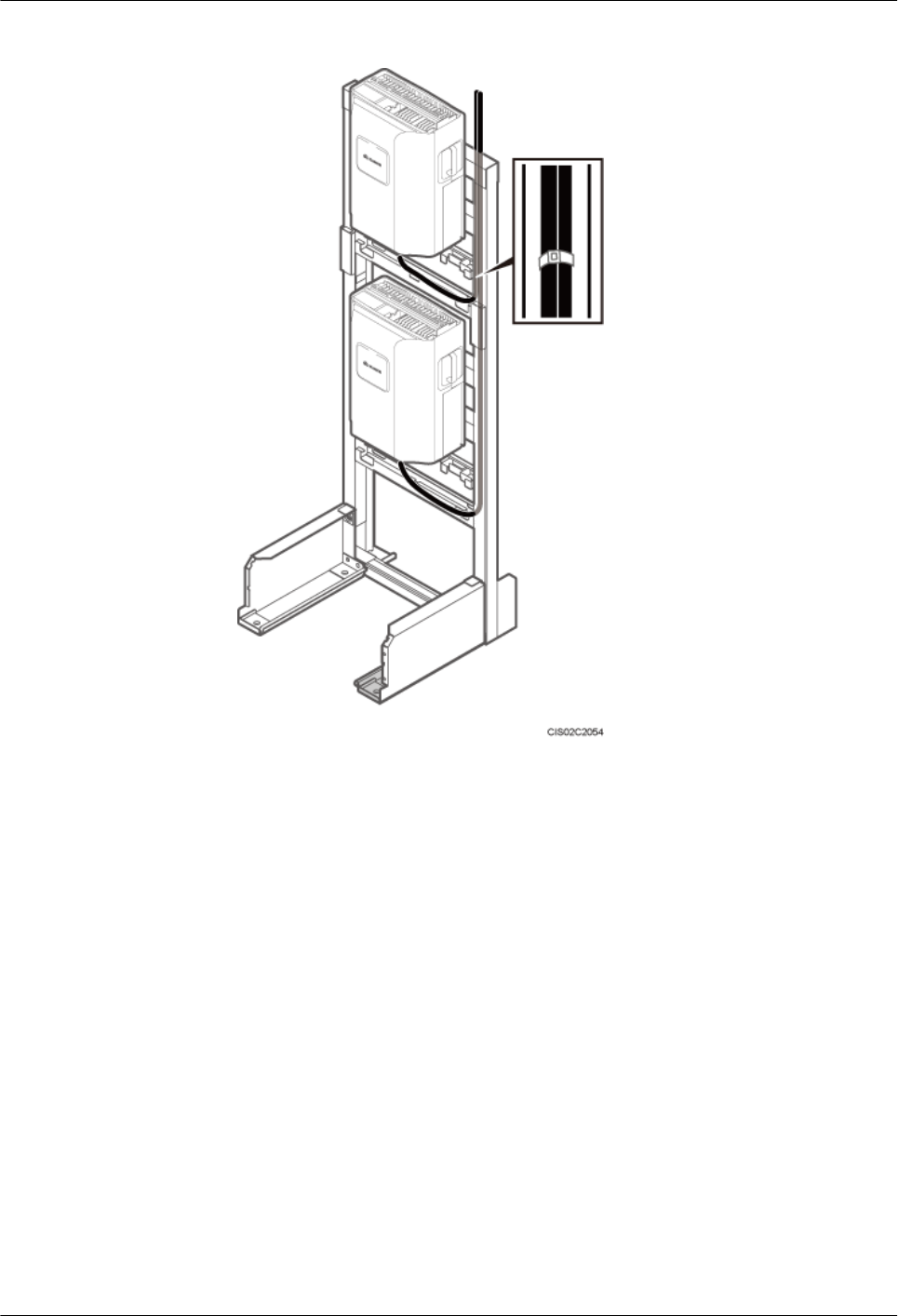
Figure 15-31 Installing the power cable for an AC RRU
5. Connect the other end of the RRU power cable to the external power system.
6. Lay out the cable according to the instructions in 15.1 Cabling Requirements, and
use cable ties to bind the cable.
7. Label the installed cable according to the instructions in Attaching a Cable-Tying
Label.
----End
15.10 (Optional) Installing BBU Inter-connection Cable
This section describes the procedure for installing inter-BBU signal cables for a base station.
Prerequisites
lA new BBU has been added.
lOptical modules and fiber optic cables meeting the following requirements are available:
–The optical modules and fiber optic cables are of the multimode type.
–The multimode optical modules to be installed on the UMPT and UCIU support the
rates of 5 Gbit/s and 2.5 Gbit/s.
DBS3900 (ICR)
Installation Guide 15 Installing Cables
Issue 12 (2015-04-30) Huawei Proprietary and Confidential
Copyright © Huawei Technologies Co., Ltd.
138
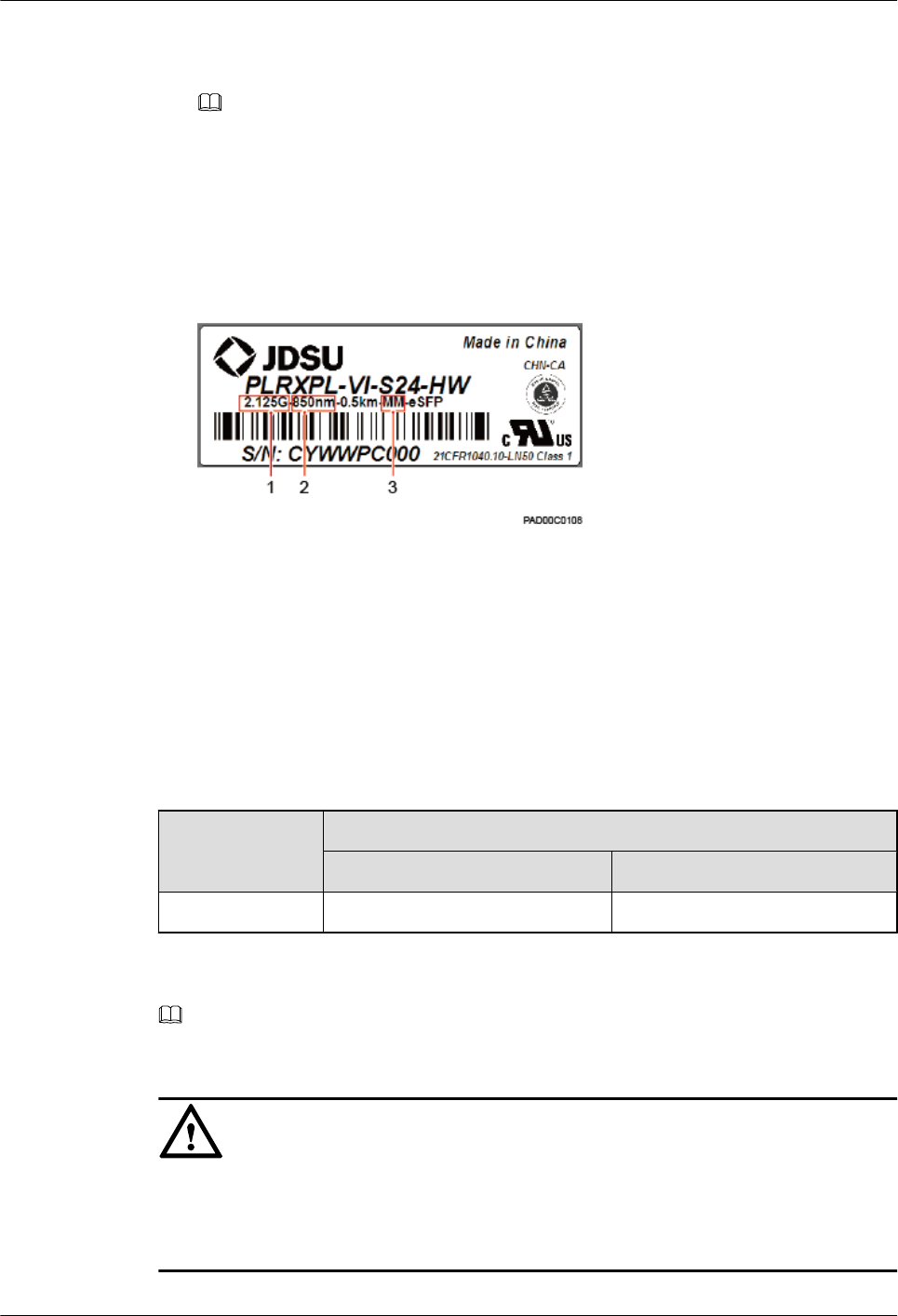
–The interconnection signal cable between the WBBPf boards in two BBUs must be a
QSFP cable.
NOTE
lSingle-mode optical modules are labeled as SM and multimode optical modules are labeled as
MM.
lThe puller of a single-mode optical module is blue. The puller of a multimode optical module is
black or gray.
lFigure 15-32 shows the label on an optical module.
Figure 15-32 Label on an optical module
(1) Maximum rate (2) Wavelength (3) Transmission mode
Context
Table 15-8 lists the BBU interconnection scenarios and the ports to which inter-BBU signal
cables are connected. For details about the BBU interconnection, see Inter-BBU Signal Cable
Connections.
Table 15-8 Ports to which inter-BBU signal cables are connected
Scenario Installation Position
BBU 0 BBU 1
UCIU+UCIU M0 port on the UCIU S0 port on the UCIU
NOTE
BBU 0 is the root BBU, and BBU 1 is the leaf BBU.
NOTICE
The performance of an optical module that is exposed to the air for more than 20 minutes may
be abnormal. Therefore, you must insert a fiber optic cable into an unpacked optical module
within 20 minutes.
DBS3900 (ICR)
Installation Guide 15 Installing Cables
Issue 12 (2015-04-30) Huawei Proprietary and Confidential
Copyright © Huawei Technologies Co., Ltd.
139
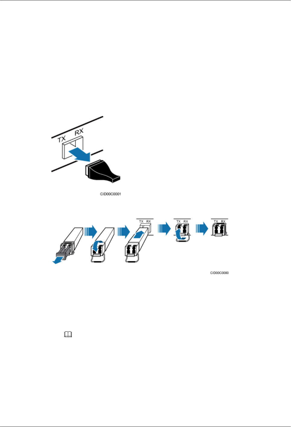
Procedure
Step 1 Determine the positions for connecting the inter-BBU signal cables according to the actual
interconnection scenarios.
Step 2 Install the optical modules in BBU 0, as shown in Figure 15-33 and Figure 15-34.
1. Remove the dustproof caps from the corresponding ports on BBU 0.
2. Lower the puller on the optical module.
3. Insert the optical modules into the ports.
4. Raise the puller on the optical module.
Figure 15-33 Removing the dustproof cap from the port
Figure 15-34 Installing the optical module
Step 3 Install the BBU inter-connection cable, as shown in Figure 15-35 and Figure 15-36.
1. Remove the dustproof caps from the optical connectors at the end labeled 2A and 2B on
the fiber optic cables, and insert the optical connectors into the optical modules in BBU 0.
2. Route the fiber optic cable to the ports on the BBU1 side.
3. On BBU 1, install optical modules of the same type as those on BBU 0.
NOTE
Optical modules with the same labels are of the same type.
4. Remove the dustproof caps from the optical connectors at the end labeled 1A and 1B on
the fiber optic cables, and insert the optical connectors into the optical modules in BBU 1.
DBS3900 (ICR)
Installation Guide 15 Installing Cables
Issue 12 (2015-04-30) Huawei Proprietary and Confidential
Copyright © Huawei Technologies Co., Ltd.
140
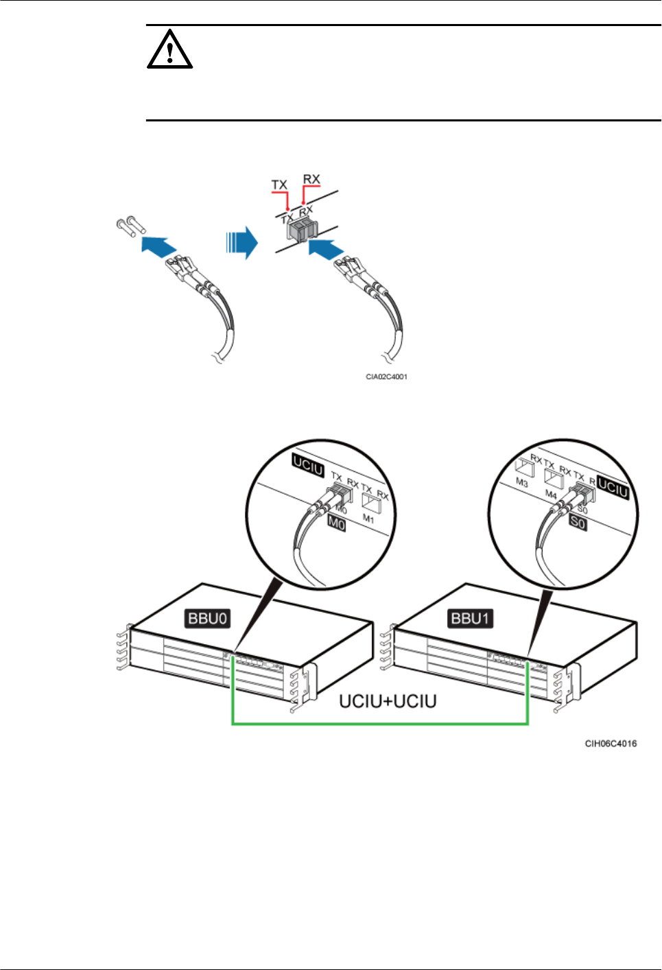
NOTICE
The TX ports on BBU 0 must be connected to the RX ports on BBU 1, and the RX ports
on BBU 0 must be connected to the TX ports on BBU 1.
Figure 15-35 Removing the dustproof cap from the fiber optic cable
Figure 15-36 Installing the BBU inter-connection cable
Step 4 Lay out the cables according to the instructions in Cabling Requirements. If a fiber optic patch
cord is used as a BBU interconnection signal cable, use binding straps to bind the BBU
interconnection signal cable before using cable ties to secure it. If another type of cable is used
as a BBU interconnection signal cable, directly use cable ties to secure it.
Step 5 Label the installed cables according to the instructions in Attaching an L-Shaped Label.
----End
DBS3900 (ICR)
Installation Guide 15 Installing Cables
Issue 12 (2015-04-30) Huawei Proprietary and Confidential
Copyright © Huawei Technologies Co., Ltd.
141

15.11 Installing Transmission Cables
This chapter describes the procedures and precautions for installing transmission cables.
15.11.1 Installing E1/T1 Cables
This section describes the procedure and precautions for installing E1/T1 cables.
Prerequisites
Ensure that both ends of the E1/T1 cables are disconnected from any equipment. Then solder
all connectors to the E1/T1 cables during the same session.
Procedure
Step 1 Connect the DB26 male connector at one end of an E1/T1 cable to the E1/T1 port on the GTMU,
and the DB26 male connector at one end of another E1/T1 cable to the E1/T1 port on the WMPT
or UMPT, as shown in Figure 15-37.
NOTE
This section describes the procedures for installing E1/T1 cables in a GU base station using independent
transmission. For the E1/T1 cable connections in other scenarios, see section "Transmission Cable
Connections" in the DBS3900 Hardware Description.
DBS3900 (ICR)
Installation Guide 15 Installing Cables
Issue 12 (2015-04-30) Huawei Proprietary and Confidential
Copyright © Huawei Technologies Co., Ltd.
142
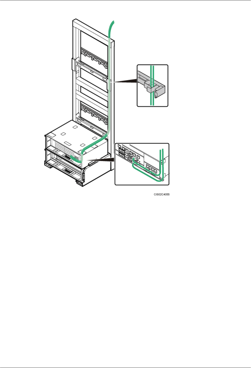
Figure 15-37 Installing E1/T1 cables
Step 2 Tighten the screws on the DB26 male connectors to 0.4 N·m (3.54 lbf·in.).
Step 3 Route the other end of the cable through the right side on the top of the IMB03. Then connect
it to the external transmission device.
Step 4 Route the cables along the right side of the cabinet according to the instructions in 15.1 Cabling
Requirements, and use cable ties to bind the cables.
Step 5 Label the installed cables according to the instructions in Attaching an L-Shaped Label.
----End
15.11.2 Installing FE/GE Ethernet Cables
This section describes the procedure and precautions for installing FE/GE Ethernet cables.
Procedure
Step 1 Connect one end of an FE/GE Ethernet cable to the FE0 port on the GTMU, and one end of
another FE/GE Ethernet cable to the FE0 port on the WMPT or FE/GE0 port on the UMPT, as
shown in Figure 15-38.
DBS3900 (ICR)
Installation Guide 15 Installing Cables
Issue 12 (2015-04-30) Huawei Proprietary and Confidential
Copyright © Huawei Technologies Co., Ltd.
143
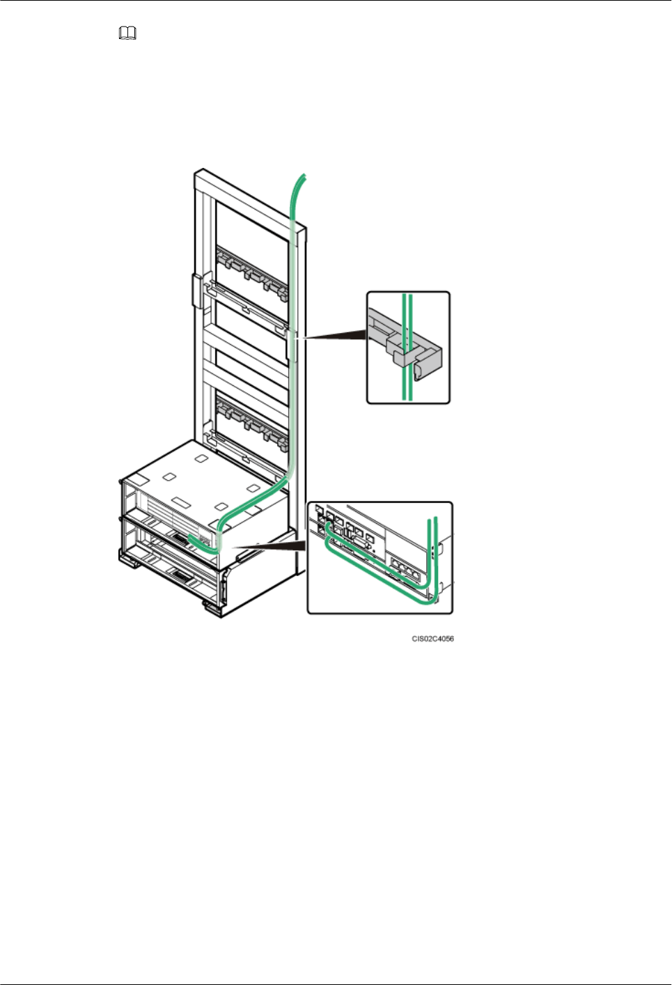
NOTE
lAn FE/GE Ethernet cable must be a shielded straight-through cable.
lThis section describes how to install FE/GE Ethernet cables in a GU base station using independent
transmission. For the FE/GE Ethernet cable connections in other configuration scenarios, see section
"Transmission Cable Connections" in the DBS3900 Hardware Description.
Figure 15-38 Installing FE/GE Ethernet cables
Step 2 Route the other end of the cable through the right side on the top of the IMB03. Then connect
it to the external transmission device.
Step 3 Route the cables along the right side of the cabinet according to the instructions in 15.1 Cabling
Requirements, and use cable ties to bind the cables.
Step 4 Label the installed cables according to the instructions in Attaching an L-Shaped Label.
----End
15.11.3 Installing FE/GE Optical Cables
This section describes the procedure and precautions for installing FE/GE optical cables.
Context
lSingle-mode optical modules are labeled as SM and multimode optical modules are labeled
as MM.
DBS3900 (ICR)
Installation Guide 15 Installing Cables
Issue 12 (2015-04-30) Huawei Proprietary and Confidential
Copyright © Huawei Technologies Co., Ltd.
144
lThe puller of a single-mode optical module is blue. The puller of a multimode optical
module is black or gray.
lAn FE/GE optical cable has an LC connector at one end and an FC connector, SC connector,
or LC connector at the other end.
lSFP0 and FE/GE0 ports on the LMPT are used for one GE input. Therefore, they are not
used simultaneously.
lSFP1 and FE/GE1 ports on the LMPT are used for another GE input. Therefore, they are
not used simultaneously.
lThis section describes how to install FE/GE optical cables in a GU base station using
independent transmission. For the FE/GE optical cable connections in other configuration
scenarios, see section "Transmission Cable Connections" in the DBS3900 Hardware
Description.
NOTICE
The performance of an optical module may deteriorate if it is exposed to the air for more than
20 minutes. Therefore, insert a fiber optic cable into an unpacked optical module within 20
minutes.
NOTICE
The optical modules to be installed must match the rates of their corresponding ports. For
example, the FE1 port (optical transmission port) on a GTMU/GTMUb /GTMUc supports only
the transmission rate of 100 Mbit/s and therefore can only use an optical module supporting the
transmission rate of 100 Mbit/s. If the port uses an optical module supporting the transmission
rate of 1000 Mbit/s, the transmission link may be disconnected.
Procedure
Step 1 Install an optical module, as shown in Figure 15-39 and Figure 15-40.
1. Remove the dustproof cap from the corresponding FE/GE optical port on the corresponding
BBU board.
2. Remove the dustproof cap from the optical module.
3. Lower the puller on the optical module.
4. Insert the optical module into the FE/GE optical port.
5. Raise the puller on the optical module.
DBS3900 (ICR)
Installation Guide 15 Installing Cables
Issue 12 (2015-04-30) Huawei Proprietary and Confidential
Copyright © Huawei Technologies Co., Ltd.
145
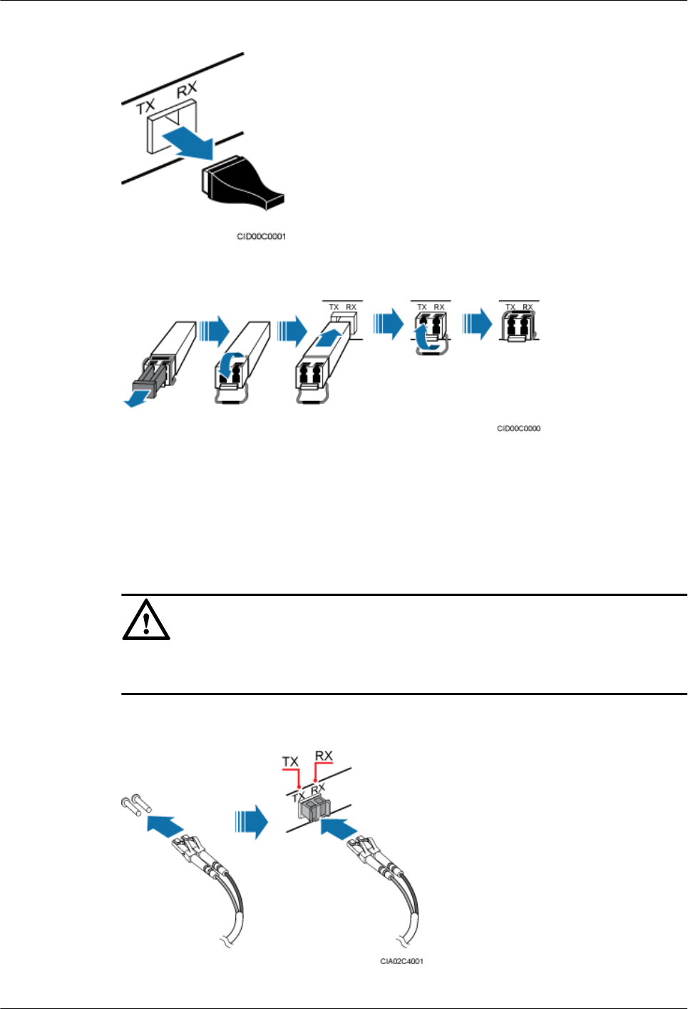
Figure 15-39 Removing the dustproof cap from the port
Figure 15-40 Installing an optical module
Step 2 Install an optical cable, as shown in Figure 15-41 and Figure 15-42.
1. Remove the dustproof caps from the connectors at the end labeled 2A and 2B on the optical
cable, and insert the connector into the optical module on the BBU.
2. Route the other end of the optical cable through the right side on the top of the IMB03.
Then connect it to the external transmission device.
NOTICE
The TX and RX ports on the BBU boards must be connected to the RX and TX ports on the
transmission equipment, respectively.
Figure 15-41 Removing the dustproof caps from the optical cable
DBS3900 (ICR)
Installation Guide 15 Installing Cables
Issue 12 (2015-04-30) Huawei Proprietary and Confidential
Copyright © Huawei Technologies Co., Ltd.
146

Figure 15-42 Installing the optical cable
Step 3 Route the cables along the right side of the cabinet according to the instructions in 15.1 Cabling
Requirements, and use cable ties to bind the cables.
Step 4 Label the installed cables according to the instructions in Attaching an L-Shaped Label.
----End
15.12 Installing CPRI Optical Cables
This section describes the procedure for installing CPRI optical cables, which transmit CPRI
signals between a BBU and RRUs.
Context
NOTE
lSingle-mode optical modules are labeled as SM and multimode optical modules are labeled as MM.
lThe puller of a single-mode optical module is blue. The puller of a multimode optical module is black
or gray.
lThe optical modules to be installed must match the rates of their corresponding ports.
DBS3900 (ICR)
Installation Guide 15 Installing Cables
Issue 12 (2015-04-30) Huawei Proprietary and Confidential
Copyright © Huawei Technologies Co., Ltd.
147
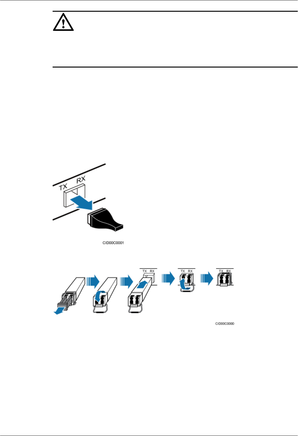
NOTICE
The performance of an optical module that is exposed to the air for more than 20 minutes may
be abnormal. Therefore, you must insert an fiber optic cable into an unpacked optical module
within 20 minutes.
Procedure
Step 1 Install an optical module on the BBU side, as shown in Figure 15-43 and Figure 15-44.
1. Remove the dustproof caps from the CPRI ports on the BBU boards.
2. Lower the puller on the optical module.
3. Insert the optical module into the CPRI port.
4. Raise the puller on the optical module.
Figure 15-43 Removing the dustproof cap from the port
Figure 15-44 Installing an optical module
Step 2 Install an optical cable, as shown in Figure 15-45, Figure 15-46, and Figure 15-47.
1. Remove the dustproof caps from the connectors at the end labeled 2A and 2B on the optical
cable, and insert the connectors into the optical module on the BBU.
2. Route the CPRI optical cable along the right side of the ICR and into the cable trough.
DBS3900 (ICR)
Installation Guide 15 Installing Cables
Issue 12 (2015-04-30) Huawei Proprietary and Confidential
Copyright © Huawei Technologies Co., Ltd.
148
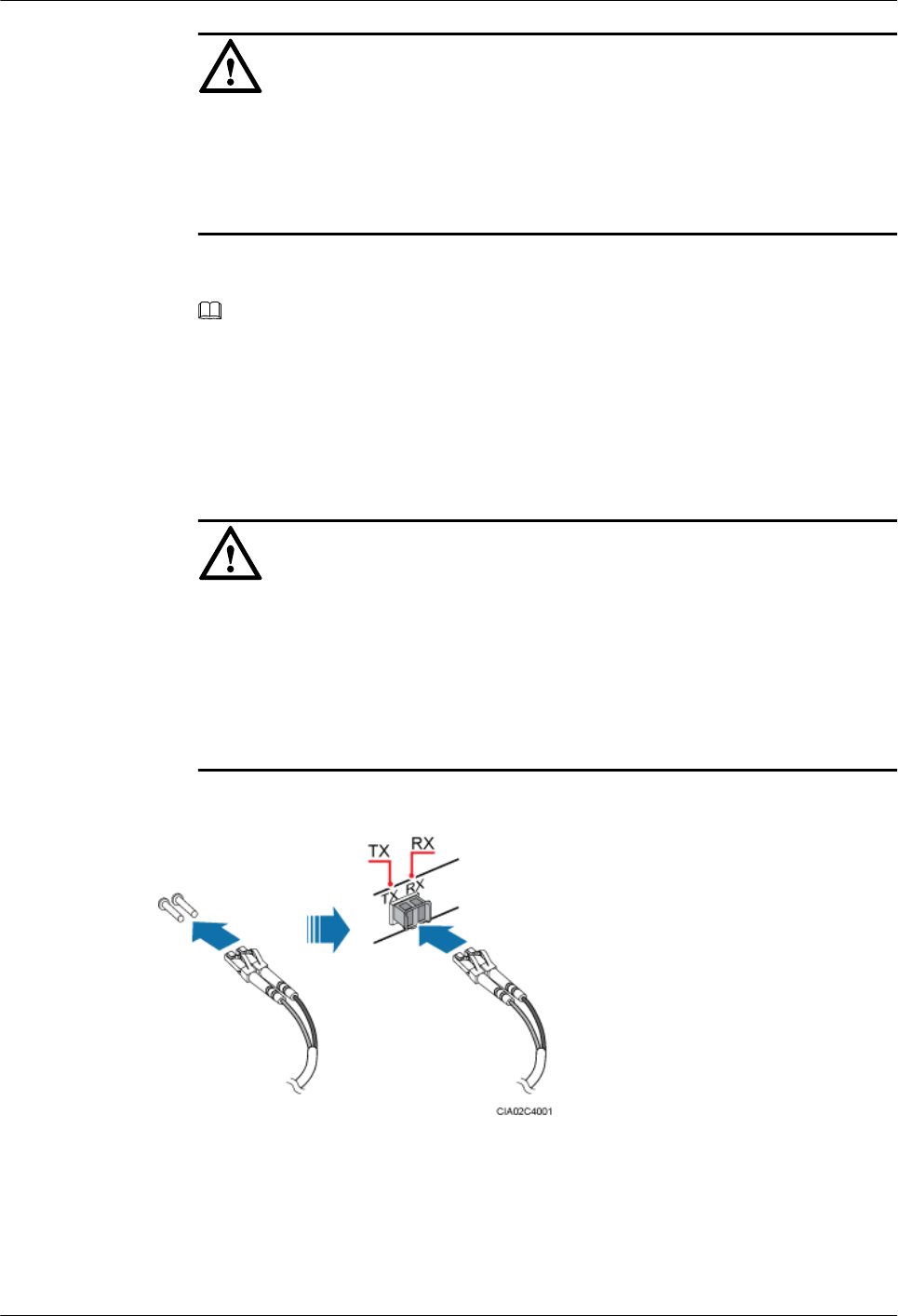
NOTICE
lWhen routing optical cables, coil the cables and place them on the top center of the
upper-level IMB03 to ensure that the holes for heat dissipation are not covered.
lThe minimum bending radius of the fiber is 140 mm. When coiling the optical cable,
do not bend it excessively.
3. Insert optical modules into the CPRI_W/CPRI0/CPRI0/IR0 ports on the RF modules. The
optical modules must be the same as those on the BBU side.
NOTE
lOptical modules with the same labels are of the same type.
lThe method of installing the CPRI optical cable for an AC RRU is the same as the method of
installing the CPRI optical cable for a DC RRU. The following figures use the CPRI optical cable
for a DC RRU as an example.
4. Remove the dustproof caps from the connectors at the end labeled 1A and 1B on the optical
cable, and insert the connectors into the optical module on the RRU.
NOTICE
lWhen a CPRI optical cable connects a BBU and an RRU, the break-out optical cables
on the BBU side and on the RRU side are 0.34 m (13.39 in.) and 0.03 m (1.18 in.),
respectively.
lIf an LC-LC optical cable is used, the TX port on the BBU must be connected to the
RX port on the RF module, and the RX port on the BBU must be connected to the TX
port on the RF module.
Figure 15-45 Removing the dustproof caps from the optical cable
DBS3900 (ICR)
Installation Guide 15 Installing Cables
Issue 12 (2015-04-30) Huawei Proprietary and Confidential
Copyright © Huawei Technologies Co., Ltd.
149
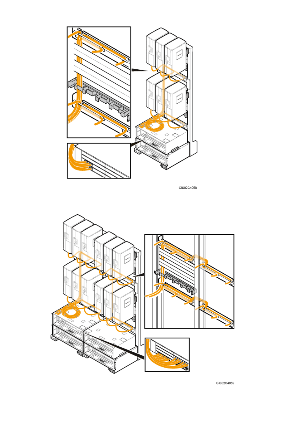
Figure 15-46 Installing the CPRI optical cable (1)
Figure 15-47 Installing the CPRI optical cable (2)
Step 3 Route the cables along the right side of the cabinet according to the instructions in 15.1 Cabling
Requirements, and use cable ties to bind the cables.
DBS3900 (ICR)
Installation Guide 15 Installing Cables
Issue 12 (2015-04-30) Huawei Proprietary and Confidential
Copyright © Huawei Technologies Co., Ltd.
150
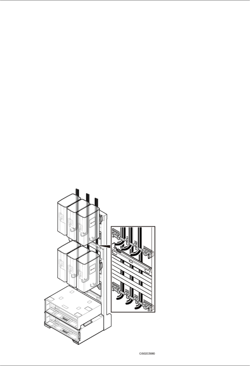
Step 4 Label the installed cables according to the instructions in Attaching an L-Shaped Label.
----End
15.13 Installing RF Jumpers
This section describes the procedure for installing RF jumpers.
Context
lWhen connecting the DIN connectors on a DC RRU's RF jumper, first connect the DIN
connector close to the cable tray and then the DIN connector at the other end. Bend an RF
jumper before connecting it to an RRU.
lRF jumpers are routed through the three slots in the middle of the cable trough. Each of the
three slots can hold four RF jumpers. Install the lower RF jumpers before the upper RF
jumpers.
lThe bending radius of an RF jumper must be more than or equal to 100 mm (3.94 in.).
Procedure
Step 1 Connect one end of the RF jumper to the RF port at the bottom of the RRU, as shown in Figure
15-48 and Figure 15-49.
Figure 15-48 Installing the RF jumper for a DC RRU
DBS3900 (ICR)
Installation Guide 15 Installing Cables
Issue 12 (2015-04-30) Huawei Proprietary and Confidential
Copyright © Huawei Technologies Co., Ltd.
151
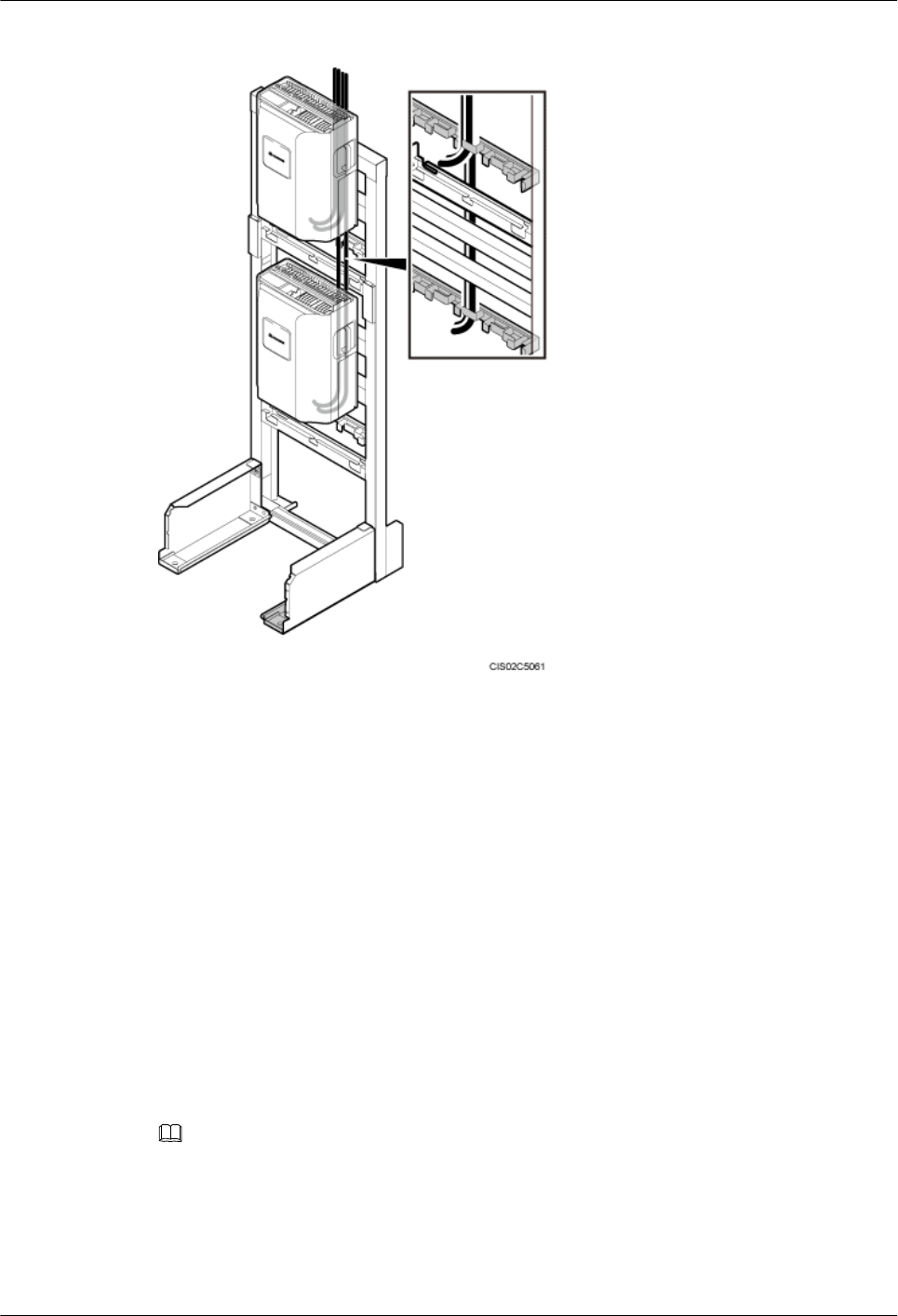
Figure 15-49 Installing the RF jumper for an AC RRU
Step 2 Connect the other end of the RF jumper to the feeder or antenna.
Step 3 Route the RF jumper along the right side of the cabinet according to the instructions in 15.1
Cabling Requirements, and use cable ties to bind the RF jumper.
Step 4 Label the installed RF jumper according to the instructions in Attaching a Sign Plate Label.
Step 5 Apply color-coding to the installed RF jumper according to the instructions in Attaching the
Color Ring.
----End
15.14 Installing the GPS Clock Signal Cable
This section describes the procedure and precautions for installing a GPS clock signal cable.
Context
NOTE
A satellite card needs to be installed onsite only for a USCU that supports the dual-satellite mode.
Procedure
Step 1 Put on an ESD wrist strap or a pair of ESD gloves.
DBS3900 (ICR)
Installation Guide 15 Installing Cables
Issue 12 (2015-04-30) Huawei Proprietary and Confidential
Copyright © Huawei Technologies Co., Ltd.
152
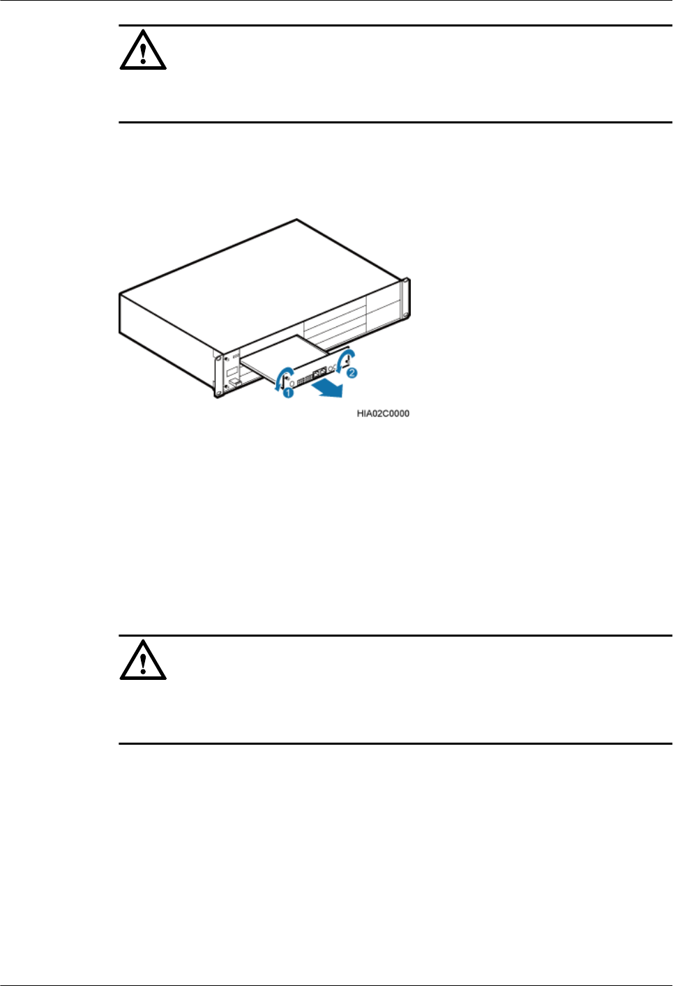
NOTICE
Take proper ESD protection measures, for example, wear an ESD wrist strap or ESD gloves, to
prevent electrostatic damage to the boards, modules, or electronic components.
Step 2 Optional: Loosen the two M3 screws on the panel, and then pull out the USCU, as shown in
Figure 15-50.
Figure 15-50 Removing the USCU.
Step 3 Optional: Install a satellite card on the USCU, as shown in Figure 15-51.
1. Remove the three M1.6 screws from the USCU.
2. Align the mounting holes on the satellite card with the bolts on the USCU.
3. Tighten the three M1.6 screws that were removed in Step 3.1 to 0.1 N·m.
4. Connect one end of the RF jumper to the RF port on the satellite card and the other end to
the GPS port on the USCU.
NOTICE
There are six mounting holes on the satellite card. You need to install only three screws on the
receiver, as shown in Figure 15-51
DBS3900 (ICR)
Installation Guide 15 Installing Cables
Issue 12 (2015-04-30) Huawei Proprietary and Confidential
Copyright © Huawei Technologies Co., Ltd.
153
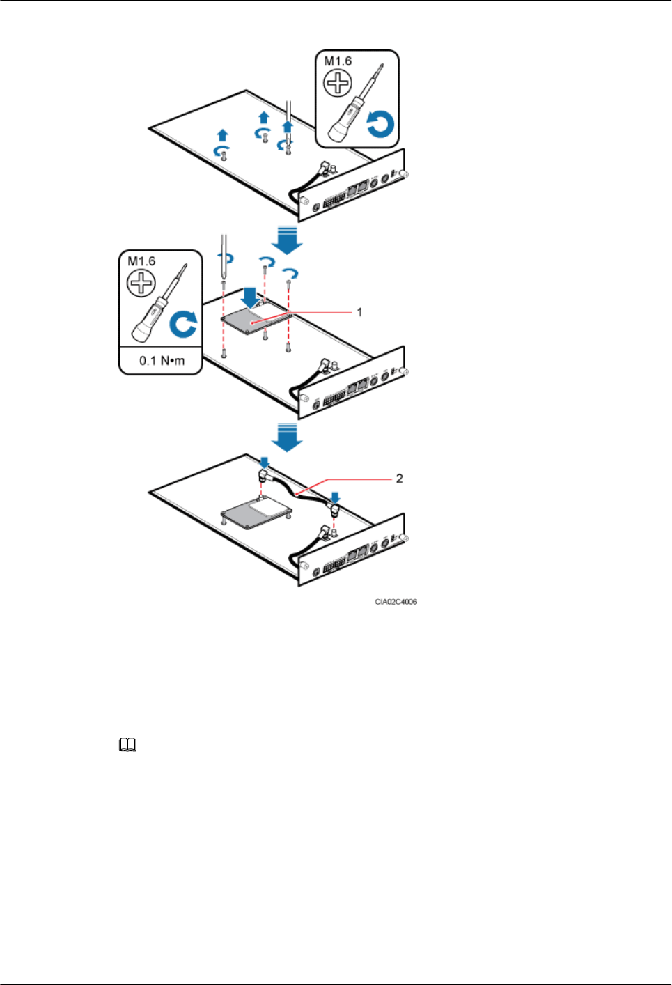
Figure 15-51 Installing the satellite card on the USCU
(1) Satellite card (2) RF jumper
Step 4 Optional: Install the USCU equipped with the satellite card into the BBU, and tighten the screws
on the USCU to 0.6 N·m.
Step 5 Connect the SMA male connector at the other end of the GPS clock signal cable to the GPS port
on the USCU or LMPT, as shown in Figure 15-52.
NOTE
If the USCU is not configured, connect the GPS clock signal cable to the GPS port on the LMPT.
DBS3900 (ICR)
Installation Guide 15 Installing Cables
Issue 12 (2015-04-30) Huawei Proprietary and Confidential
Copyright © Huawei Technologies Co., Ltd.
154
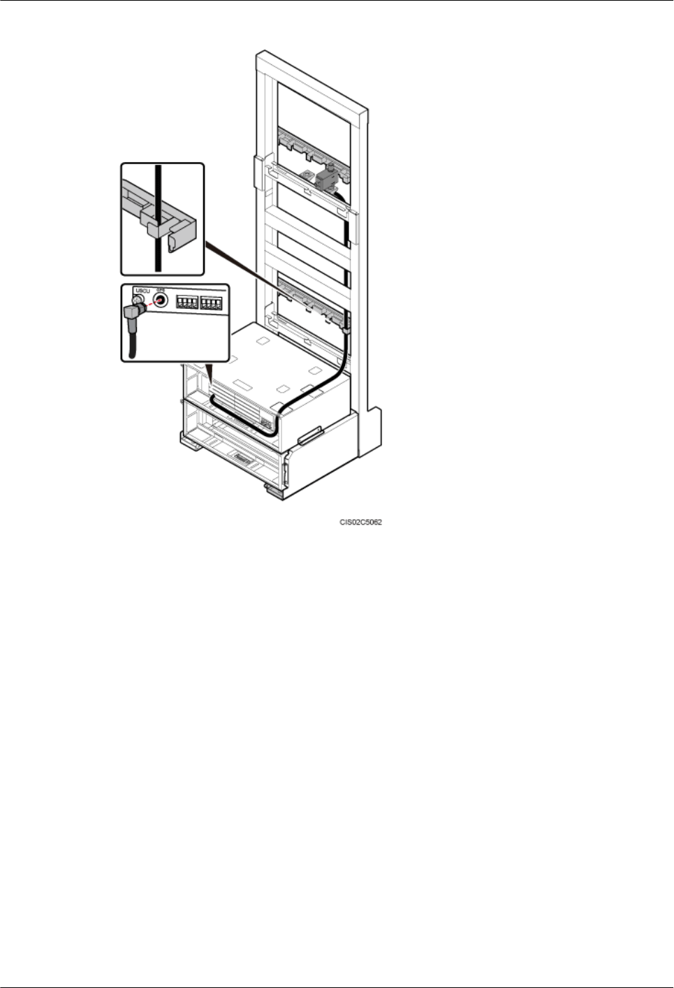
Figure 15-52 Installing the GPS clock signal cable
Step 6 Install the GPS jumper, as shown in Figure 15-53.
1. Cut the cable to a length suitable for the actual cable route.
2. Install an N50 straight male connector at each end of the cable according to the instructions
in Installing the Type N Coaxial Connector.
3. Connect one end of the cable to the type N female connector (labeled Surge) on the GPS
surge protector.
4. Route the other end of the cable along the right side of the IFS06. Then connect it to the
external GPS antenna.
DBS3900 (ICR)
Installation Guide 15 Installing Cables
Issue 12 (2015-04-30) Huawei Proprietary and Confidential
Copyright © Huawei Technologies Co., Ltd.
155
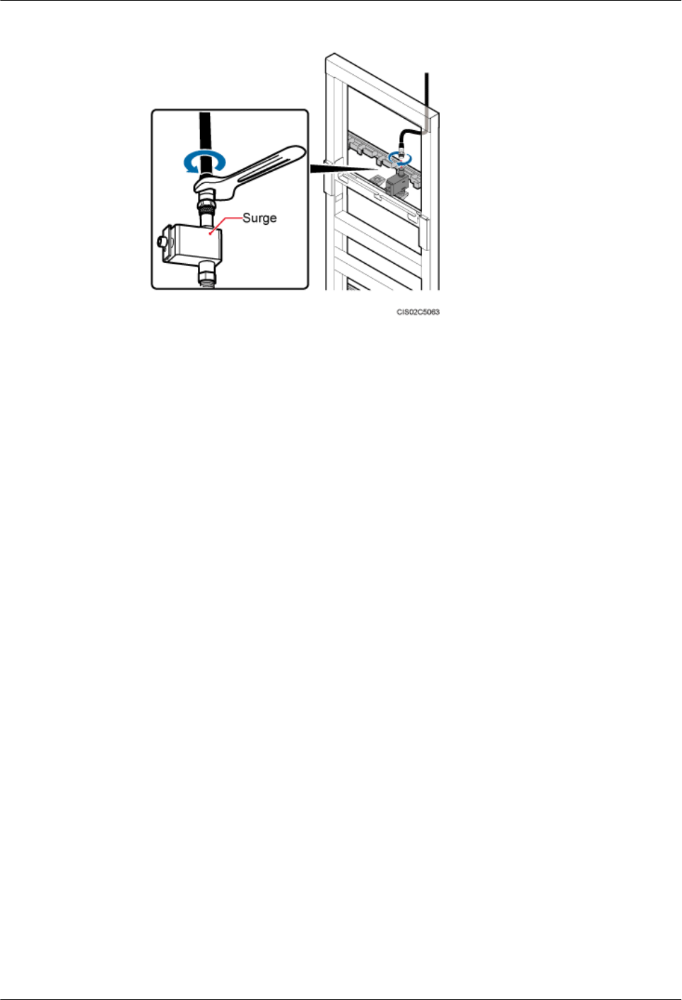
Figure 15-53 Installing the GPS jumper
Step 7 Lay out the cable according to the instructions in 15.1 Cabling Requirements, and use cable
ties to bind the cable.
Step 8 Label the installed cable according to the instructions in Attaching a Sign Plate Label.
----End
DBS3900 (ICR)
Installation Guide 15 Installing Cables
Issue 12 (2015-04-30) Huawei Proprietary and Confidential
Copyright © Huawei Technologies Co., Ltd.
156

16 Installation Checklist
This chapter describes the hardware installation checklist.
Table 16-1 Hardware installation checklist
No. Item
1The position for each device conforms to the engineering drawing and meets
clearance requirements. Sufficient space is reserved for equipment maintenance.
2 The BBU, RRUs, and auxiliary devices are securely installed, and all screws are
tightened.
3 The DIP switch on the BBU is correctly set.
4 The cover plate is securely installed on the RRU cabling cavity.
5 None of power cables and PGND cables are short-circuited or reversely connected.
In addition, these cables are not damaged or broken.
6 There are no connectors or joints on each power cable or PGND cable.
7 The terminals at both ends of the power cable or PGND cable are securely soldered
or crimped.
8 Bare wires and OT terminals at the wiring terminals are tightly wrapped with
insulation tapes or heat shrink tubing.
9 The work grounding and protection grounding of the base station share one group
of ground bodies with the surge protection grounding of the building.
10 The connectors of each signal cable are intact, and these cables are not damaged
or broken.
11 The distance between the bundled fibers and the BBU panel is between 40 mm
(1.57 in.) and 70 mm (2.76 in.). This avoids the interference by the cover plate of
the IMB03.
12 Labels are correct, legible, and complete at both ends of each cable.
DBS3900 (ICR)
Installation Guide 16 Installation Checklist
Issue 12 (2015-04-30) Huawei Proprietary and Confidential
Copyright © Huawei Technologies Co., Ltd.
157
17 Power-On Check
Before powering on a base station, field engineers need to check the power-on status of the
cabinet and its components.
NOTICE
lPower on a component within 7 days after unpacking it. If you power off the component
for maintenance, restore power to the component within 48 hours.
lPower on an RRU within 24 hours after unpacking it. If you power off an RRU for
maintenance, restore power to the RRU within 24 hours.
Power-On Check
Figure 17-1 shows the power-on check process.
DBS3900 (ICR)
Installation Guide 17 Power-On Check
Issue 12 (2015-04-30) Huawei Proprietary and Confidential
Copyright © Huawei Technologies Co., Ltd.
158
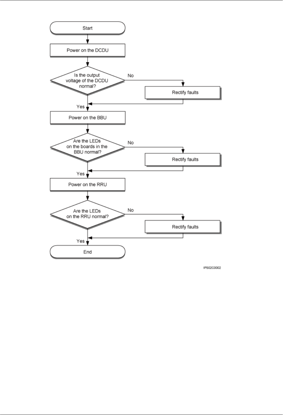
Figure 17-1 Power-on check
Checking the Indicator Status and Output Voltage Range
The DC output voltage of the DCDU ranges from -43.2 V DC to -57 V DC.
The normal status of the indicators on the BBU is as follows:
lUPEU: The RUN indicator is steady green.
lFAN: The STATE indicator blinks green (on for 1s and off for 1s).
lOther BBU boards: The RUN indicator blinks green (on for 1s and off for 1s).
The normal status of the indicators on the RRU is as follows:
lThe RUN indicator blinks green (on for 1s and off for 1s).
DBS3900 (ICR)
Installation Guide 17 Power-On Check
Issue 12 (2015-04-30) Huawei Proprietary and Confidential
Copyright © Huawei Technologies Co., Ltd.
159
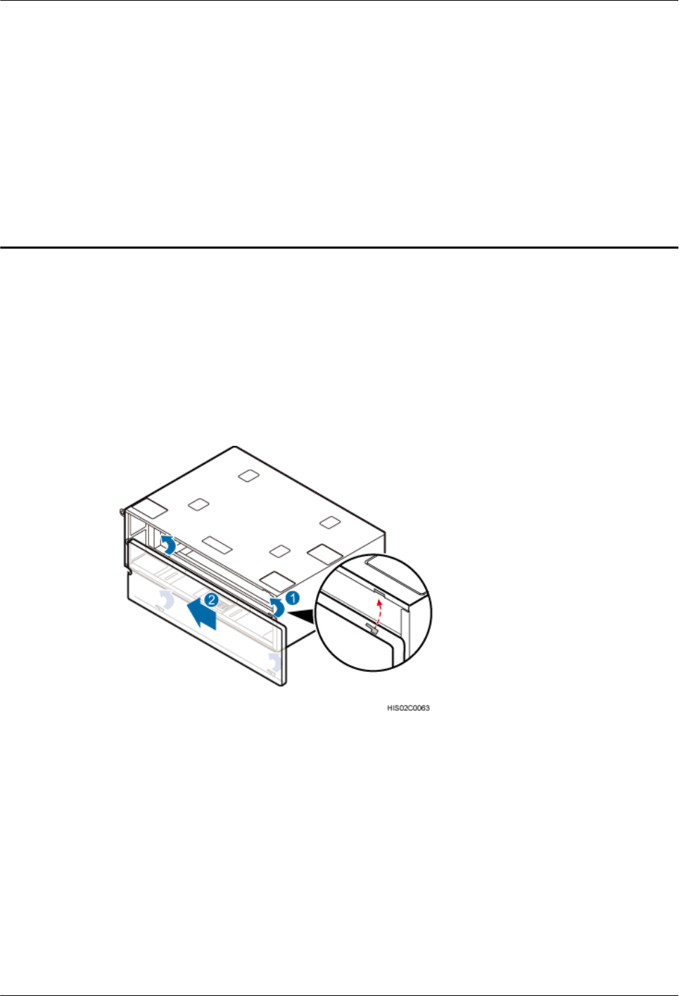
18 Installing the Cover Plate of the IMB03
This chapter describes the procedure for installing the cover plate of the IMB03.
Procedure
Step 1 Fit the tabs on the cover plate into the slots in the IMB03, as shown in Figure 18-1.
Figure 18-1 Installing the cover plate
Step 2 Use a Phillips screwdriver to tighten the M3x8 bolts on the right side of the cover plate to 0.3
N·m (2.66 lbf·in.), as shown in Figure 18-2.
DBS3900 (ICR)
Installation Guide 18 Installing the Cover Plate of the IMB03
Issue 12 (2015-04-30) Huawei Proprietary and Confidential
Copyright © Huawei Technologies Co., Ltd.
160
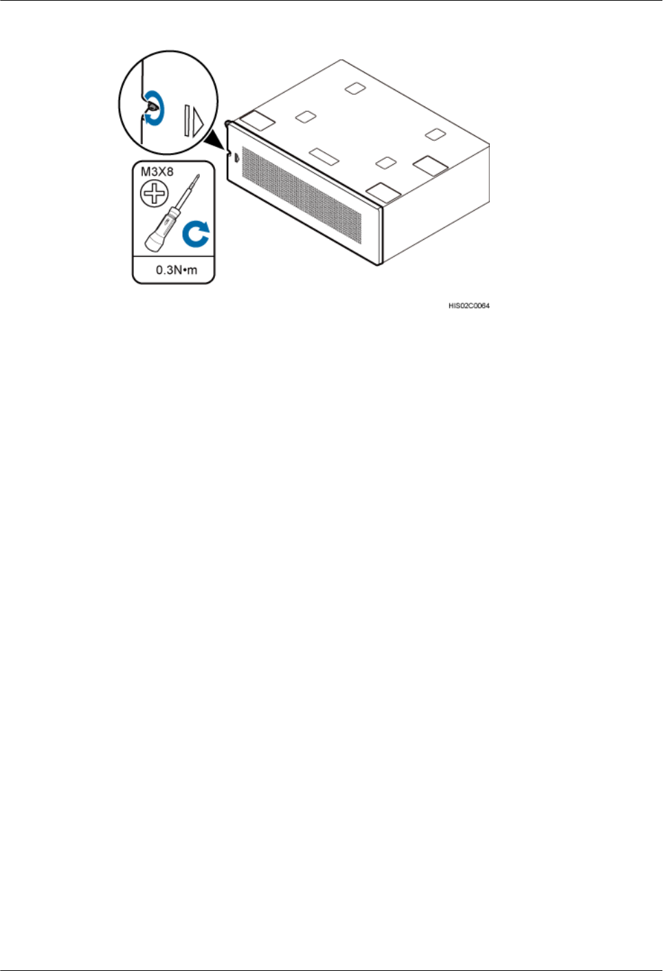
Figure 18-2 Securing the cover plate
----End
DBS3900 (ICR)
Installation Guide 18 Installing the Cover Plate of the IMB03
Issue 12 (2015-04-30) Huawei Proprietary and Confidential
Copyright © Huawei Technologies Co., Ltd.
161