Huawei Technologies RRU3279-2600 Remote Radio Unit of Distributed Base Station User Manual Hardware Maintenance Guide
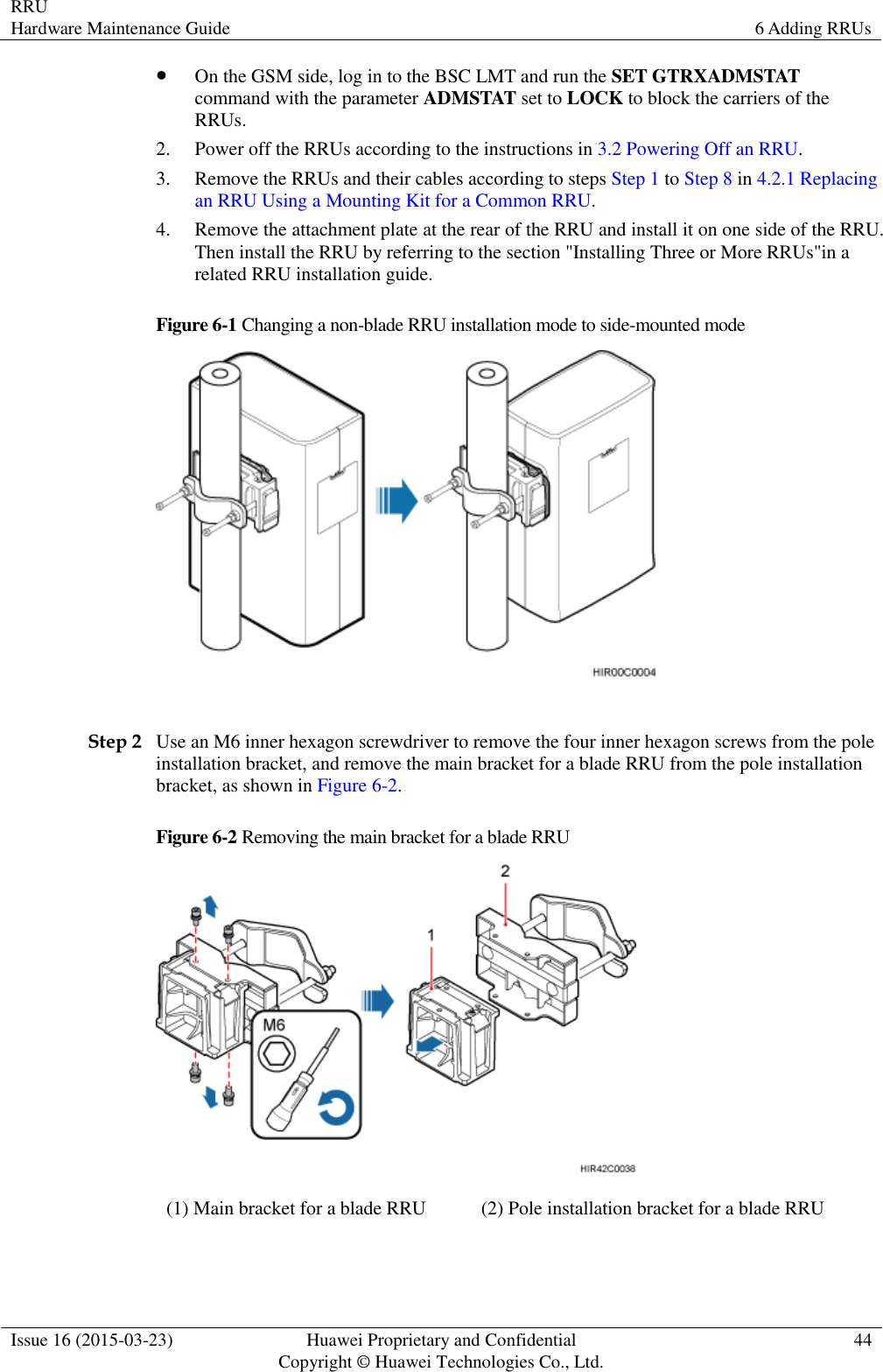
Huawei Technologies Co.,Ltd Remote Radio Unit of Distributed Base Station Hardware Maintenance Guide
UserManual.wiki
>
Huawei Technologies
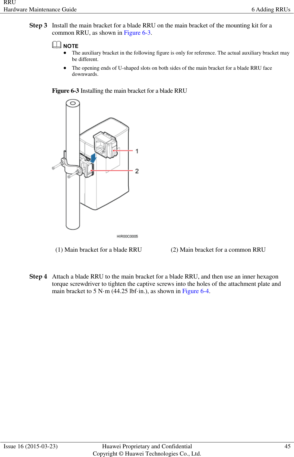
>
RRU3279 2600 User Manual
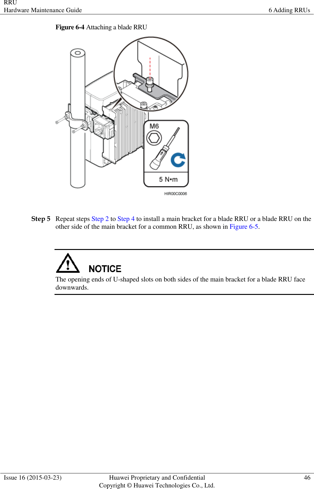
User Manual
Navigation menu
Upload a User Manual
Namespaces
Wiki Guide
HTML
PDF
Info
Views
User Manual
Discussion / Help
Navigation
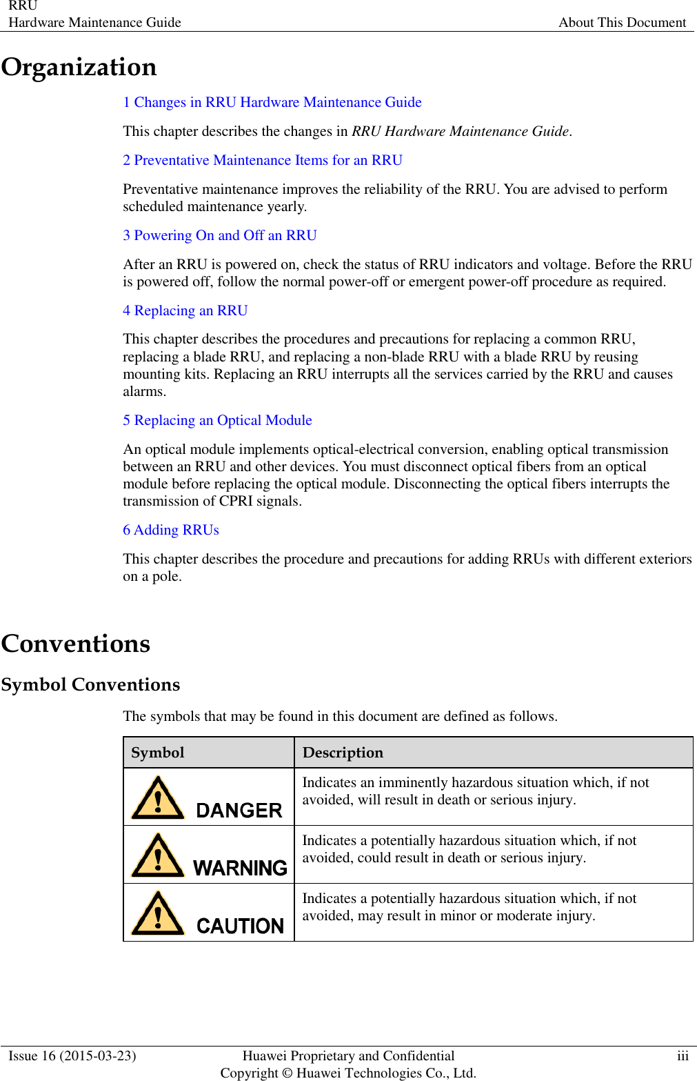
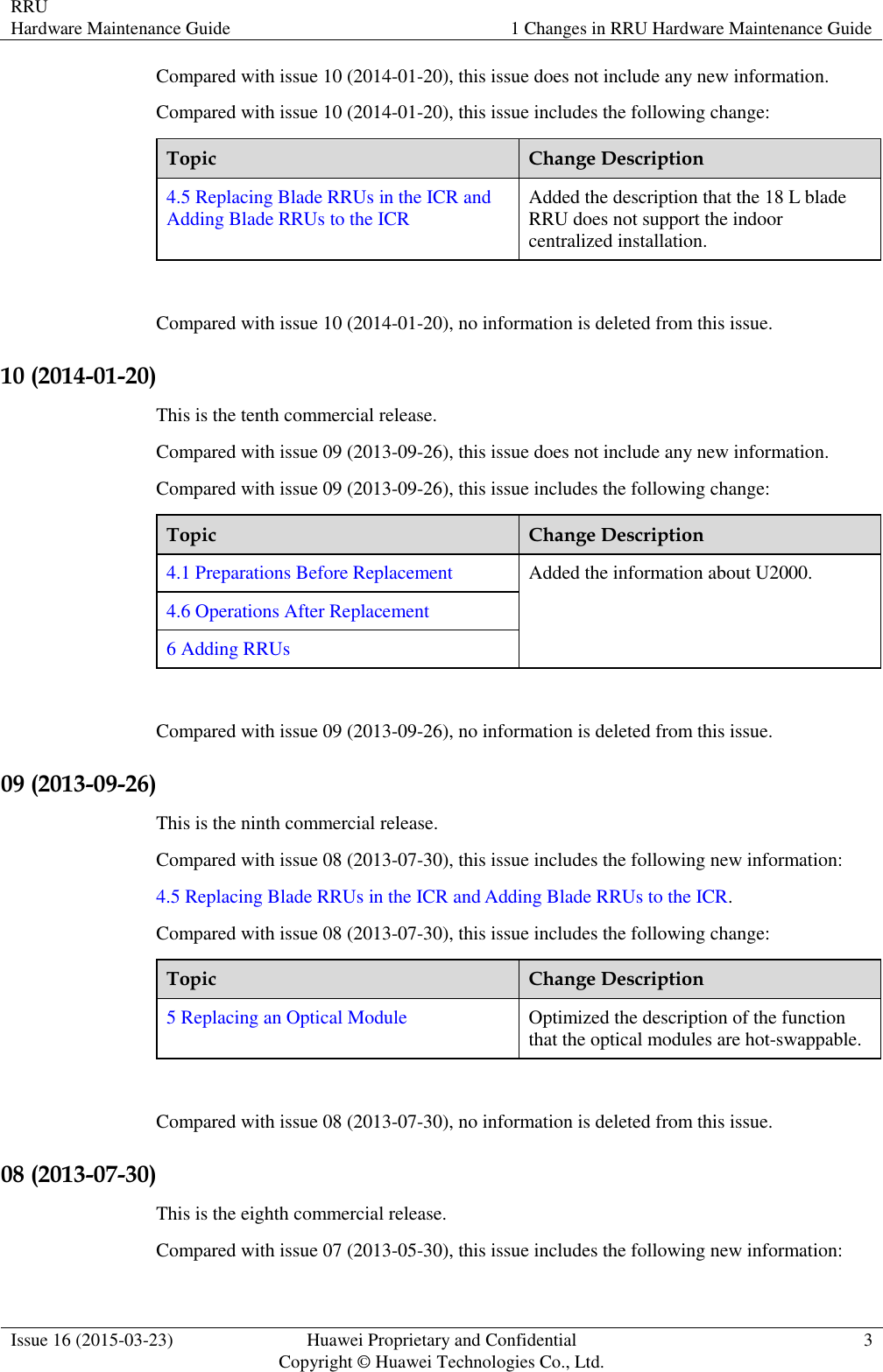
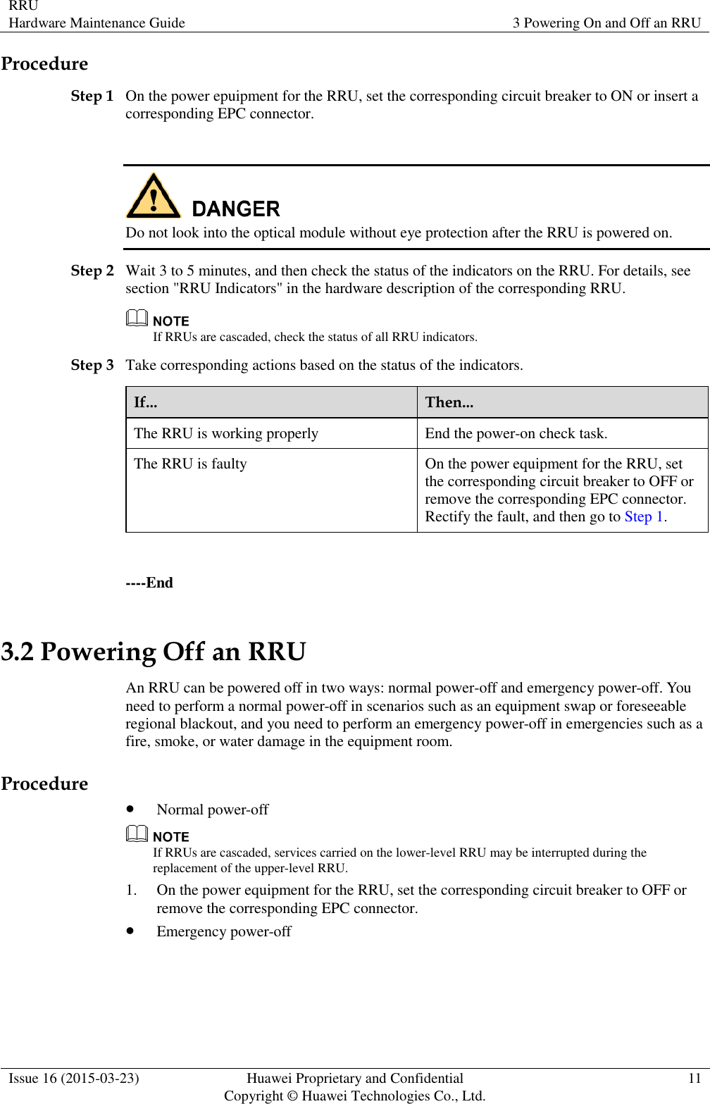
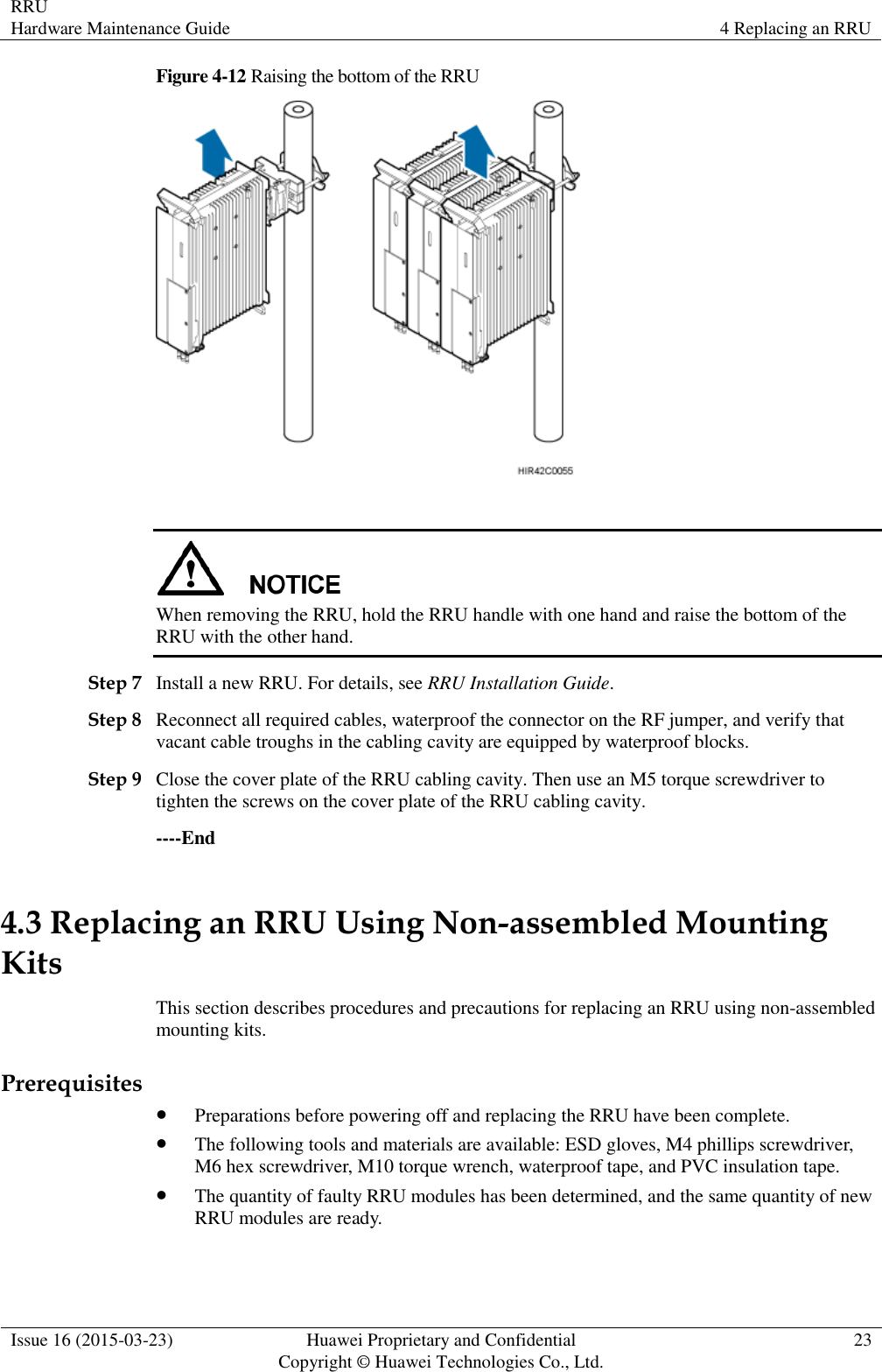
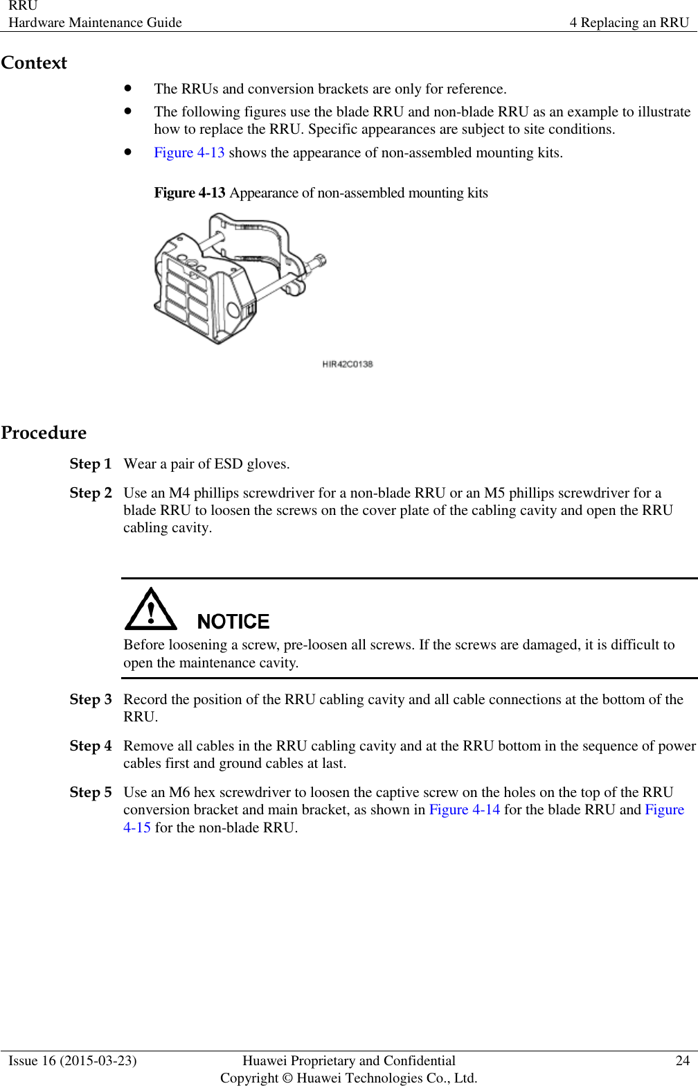
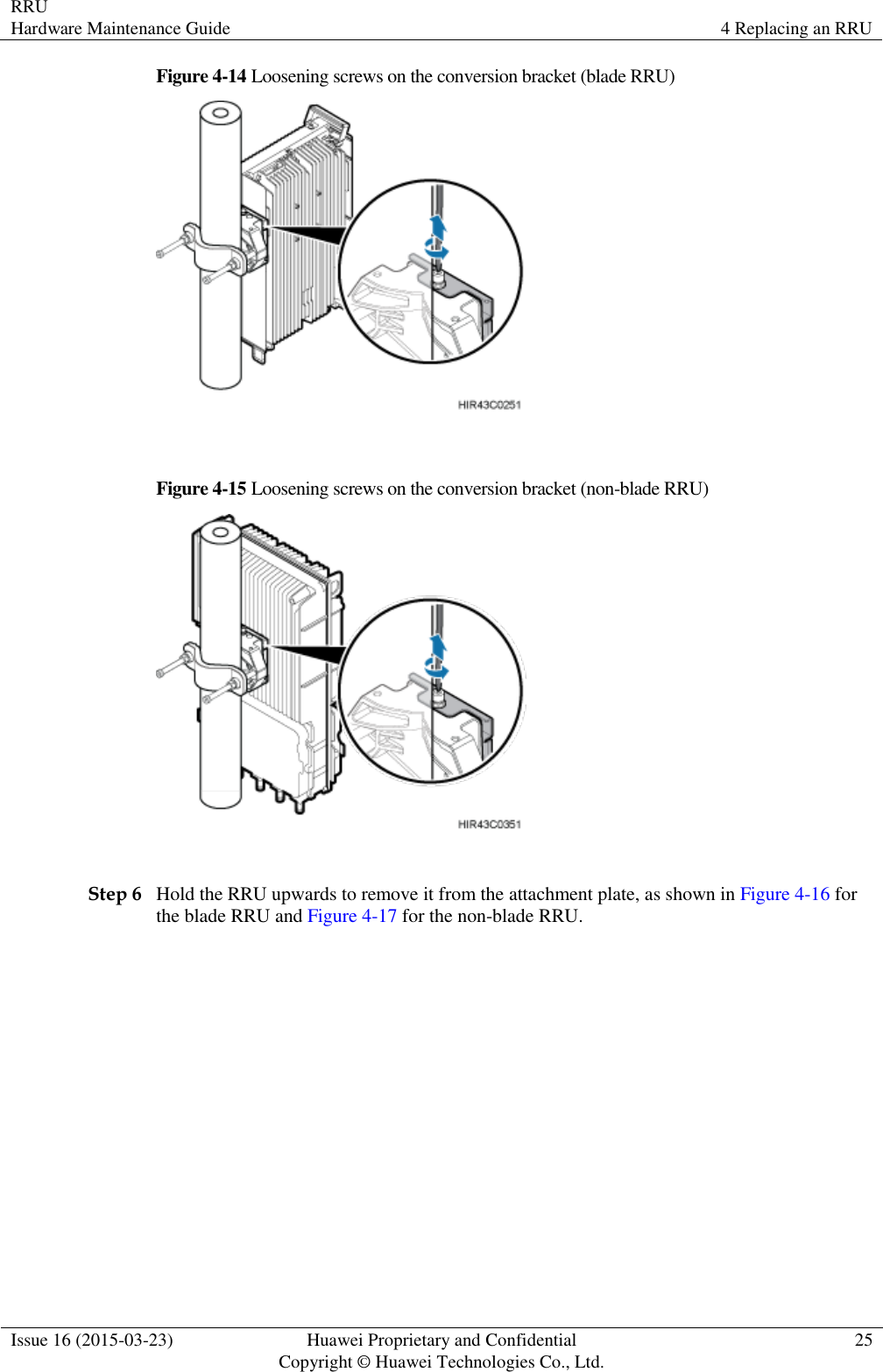
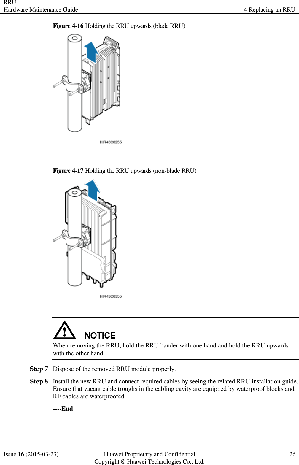
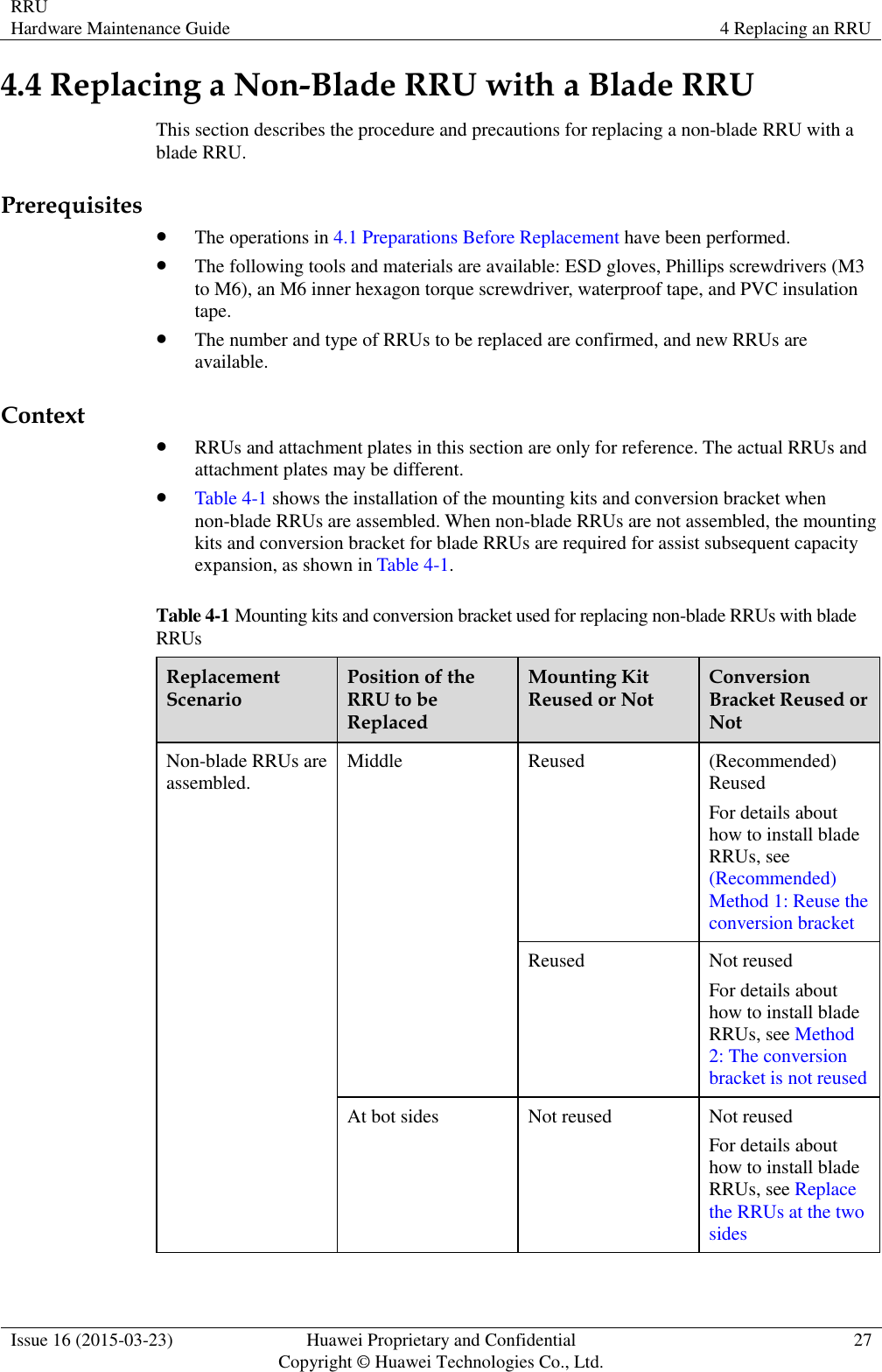
![RRU Hardware Maintenance Guide About This Document Issue 16 (2015-03-23) Huawei Proprietary and Confidential Copyright © Huawei Technologies Co., Ltd. iv Symbol Description Indicates a potentially hazardous situation which, if not avoided, could result in equipment damage, data loss, performance deterioration, or unanticipated results. NOTICE is used to address practices not related to personal injury. Calls attention to important information, best practices and tips. NOTE is used to address information not related to personal injury, equipment damage, and environment deterioration. General Conventions Convention Description Times New Roman Normal paragraphs are in Times New Roman. Boldface Names of files, directories, folders, and users are in boldface. For example, log in as user root. Italic Book titles are in italics. Courier New Terminal display is in Courier New. Command Conventions Convention Description Boldface The keywords of a command line are in boldface. Italic Command arguments are in italics. [ ] Items (keywords or arguments) in brackets [ ] are optional. { x | y | ... } Optional items are grouped in braces and separated by vertical bars. One item is selected. [ x | y | ... ] Optional items are grouped in brackets and separated by vertical bars. One item is selected or no item is selected. { x | y | ... } * Optional items are grouped in braces and separated by vertical bars. A minimum of one item or a maximum of all items can be selected. [ x | y | ... ] * Optional items are grouped in brackets and separated by vertical bars. Several items or no item can be selected.](https://usermanual.wiki/Huawei-Technologies/RRU3279-2600/User-Guide-2680886-Page-5.png)