Huawei Technologies RRU3279-2600 Remote Radio Unit of Distributed Base Station User Manual Hardware Maintenance Guide
Huawei Technologies Co.,Ltd Remote Radio Unit of Distributed Base Station Hardware Maintenance Guide
User Manual

RRU
Hardware Maintenance Guide
Issue
16
Date
2015-03-23
HUAWEI TECHNOLOGIES CO., LTD.

Issue 16 (2015-03-23)
Huawei Proprietary and Confidential
Copyright © Huawei Technologies Co., Ltd.
i
Copyright © Huawei Technologies Co., Ltd. 2015. All rights reserved.
No part of this document may be reproduced or transmitted in any form or by any means without prior
written consent of Huawei Technologies Co., Ltd.
Trademarks and Permissions
and other Huawei trademarks are trademarks of Huawei Technologies Co., Ltd.
All other trademarks and trade names mentioned in this document are the property of their respective
holders.
Notice
The purchased products, services and features are stipulated by the contract made between Huawei and
the customer. All or part of the products, services and features described in this document may not be
within the purchase scope or the usage scope. Unless otherwise specified in the contract, all statements,
information, and recommendations in this document are provided "AS IS" without warranties, guarantees or
representations of any kind, either express or implied.
The information in this document is subject to change without notice. Every effort has been made in the
preparation of this document to ensure accuracy of the contents, but all statements, information, and
recommendations in this document do not constitute a warranty of any kind, express or implied.
Huawei Technologies Co., Ltd.
Address:
Huawei Industrial Base
Bantian, Longgang
Shenzhen 518129
People's Republic of China
Website:
http://www.huawei.com
Email:
support@huawei.com
RRU
Hardware Maintenance Guide
About This Document
Issue 16 (2015-03-23)
Huawei Proprietary and Confidential
Copyright © Huawei Technologies Co., Ltd.
ii
About This Document
Purpose
This document describes routine maintenance procedures for an RRU such as equipment
maintenance and power-on and power-off operations. It also explains how to replace the RRU
and optical modules.
The RRUs involved in this document are the RRUs in SingleRAN, GSM, UMTS, LTE FDD,
and LTE TDD modes.
If LTE is used rather than LTE FDD or LTE TDD in this document, the LTE mode can be the LTE FDD
mode or LTE TDD mode. If eNodeB is used rather than eNodeB FDD or eNodeB TDD in this document,
the eNodeB can be an eNodeB FDD or a eNodeB TDD.
Product Versions
The following table lists the product versions related to this document.
Product Name
Solution Version
Product Version
DBS3900
SRAN6.0 and later versions
V100R004C00 and later
versions
GBSS13.0 and later versions
V100R013C00 and later
versions
RAN13.0 and later versions
V200R013C00 and later
versions
eRAN2.1 and later versions
V100R003C00 and later
versions
eRAN2.1 TDD and later
versions
V100R003C00 and later
versions
Intended Audience
This document is intended for:
System engineers
Site maintenance personnel

RRU
Hardware Maintenance Guide
About This Document
Issue 16 (2015-03-23)
Huawei Proprietary and Confidential
Copyright © Huawei Technologies Co., Ltd.
iii
Organization
1 Changes in RRU Hardware Maintenance Guide
This chapter describes the changes in RRU Hardware Maintenance Guide.
2 Preventative Maintenance Items for an RRU
Preventative maintenance improves the reliability of the RRU. You are advised to perform
scheduled maintenance yearly.
3 Powering On and Off an RRU
After an RRU is powered on, check the status of RRU indicators and voltage. Before the RRU
is powered off, follow the normal power-off or emergent power-off procedure as required.
4 Replacing an RRU
This chapter describes the procedures and precautions for replacing a common RRU,
replacing a blade RRU, and replacing a non-blade RRU with a blade RRU by reusing
mounting kits. Replacing an RRU interrupts all the services carried by the RRU and causes
alarms.
5 Replacing an Optical Module
An optical module implements optical-electrical conversion, enabling optical transmission
between an RRU and other devices. You must disconnect optical fibers from an optical
module before replacing the optical module. Disconnecting the optical fibers interrupts the
transmission of CPRI signals.
6 Adding RRUs
This chapter describes the procedure and precautions for adding RRUs with different exteriors
on a pole.
Conventions
Symbol Conventions
The symbols that may be found in this document are defined as follows.
Symbol
Description
Indicates an imminently hazardous situation which, if not
avoided, will result in death or serious injury.
Indicates a potentially hazardous situation which, if not
avoided, could result in death or serious injury.
Indicates a potentially hazardous situation which, if not
avoided, may result in minor or moderate injury.
RRU
Hardware Maintenance Guide
About This Document
Issue 16 (2015-03-23)
Huawei Proprietary and Confidential
Copyright © Huawei Technologies Co., Ltd.
iv
Symbol
Description
Indicates a potentially hazardous situation which, if not
avoided, could result in equipment damage, data loss,
performance deterioration, or unanticipated results.
NOTICE is used to address practices not related to personal
injury.
Calls attention to important information, best practices and
tips.
NOTE is used to address information not related to personal
injury, equipment damage, and environment deterioration.
General Conventions
Convention
Description
Times New Roman
Normal paragraphs are in Times New Roman.
Boldface
Names of files, directories, folders, and users are in
boldface. For example, log in as user root.
Italic
Book titles are in italics.
Courier New
Terminal display is in Courier New.
Command Conventions
Convention
Description
Boldface
The keywords of a command line are in boldface.
Italic
Command arguments are in italics.
[ ]
Items (keywords or arguments) in brackets [ ] are optional.
{ x | y | ... }
Optional items are grouped in braces and separated by
vertical bars. One item is selected.
[ x | y | ... ]
Optional items are grouped in brackets and separated by
vertical bars. One item is selected or no item is selected.
{ x | y | ... } *
Optional items are grouped in braces and separated by
vertical bars. A minimum of one item or a maximum of all
items can be selected.
[ x | y | ... ] *
Optional items are grouped in brackets and separated by
vertical bars. Several items or no item can be selected.
RRU
Hardware Maintenance Guide
About This Document
Issue 16 (2015-03-23)
Huawei Proprietary and Confidential
Copyright © Huawei Technologies Co., Ltd.
v
GUI Conventions
Convention
Description
Boldface
Buttons, menus, parameters, tabs, windows, and dialog titles
are in boldface. For example, click OK.
>
Multi-level menus are in boldface and separated by the ">"
signs. For example, choose File > Create > Folder.
Keyboard Operation
Format
Description
Key
Press the key. For example, press Enter and press Tab.
Key 1+Key 2
Press the keys concurrently. For example, pressing
Ctrl+Alt+A means the three keys should be pressed
concurrently.
Key 1, Key 2
Press the keys in turn. For example, pressing Alt, A means
the two keys should be pressed in turn.
Mouse Operation
Action
Description
Click
Select and release the primary mouse button without
moving the pointer.
Double-click
Press the primary mouse button twice continuously and
quickly without moving the pointer.
Drag
Press and hold the primary mouse button and move the
pointer to a certain position.

RRU
Hardware Maintenance Guide
Contents
Issue 16 (2015-03-23)
Huawei Proprietary and Confidential
Copyright © Huawei Technologies Co., Ltd.
vi
Contents
About This Document .................................................................................................................... ii
1 Changes in RRU Hardware Maintenance Guide .................................................................... 1
2 Preventative Maintenance Items for an RRU .......................................................................... 8
3 Powering On and Off an RRU .................................................................................................. 10
3.1 Powering On an RRU ................................................................................................................................................. 10
3.2 Powering Off an RRU ................................................................................................................................................. 11
4 Replacing an RRU ....................................................................................................................... 13
4.1 Preparations Before Replacement ............................................................................................................................... 13
4.2 Replacing an RRU Using Assembled Mounting Kits ................................................................................................. 15
4.2.1 Replacing an RRU Using a Mounting Kit for a Common RRU .............................................................................. 15
4.2.2 Replacing an RRU Using a Mounting Kit for a Blade RRU ................................................................................... 20
4.3 Replacing an RRU Using Non-assembled Mounting Kits .......................................................................................... 23
4.4 Replacing a Non-Blade RRU with a Blade RRU ....................................................................................................... 27
4.5 Replacing Blade RRUs in the ICR and Adding Blade RRUs to the ICR .................................................................... 33
4.6 Operations After Replacement .................................................................................................................................... 38
5 Replacing an Optical Module ................................................................................................... 40
6 Adding RRUs ............................................................................................................................... 43
RRU
Hardware Maintenance Guide
1 Changes in RRU Hardware Maintenance Guide
Issue 16 (2015-03-23)
Huawei Proprietary and Confidential
Copyright © Huawei Technologies Co., Ltd.
1
1 Changes in RRU Hardware Maintenance
Guide
This chapter describes the changes in RRU Hardware Maintenance Guide.
16 (2015-03-23)
This is the sixteenth commercial release.
Compared with issue 15 (2015-02-10), this issue does not include any new information.
Compared with issue 15 (2015-02-10), this issue includes the following change:
Topic
Change Description
3.2 Powering Off an RRU
Added the procedure of checking whether
the power-off operation succeeds.
4.2.1 Replacing an RRU Using a Mounting
Kit for a Common RRU
4.2.2 Replacing an RRU Using a Mounting
Kit for a Blade RRU
Added the procedure and caution.
Compared with issue 15 (2015-02-10), no information is deleted from this issue.
15 (2015-02-10)
This is the fifteenth commercial release.
Compared with issue 14 (2015-01-30), this issue does not include any new information.
Compared with issue 14 (2015-01-30), this issue includes the following change:
Topic
Change Description
4.4 Replacing a Non-Blade RRU with a
Blade RRU
Modified the context and procedure of
replacing a Non-Blade RRU with a Blade
RRU.
RRU
Hardware Maintenance Guide
1 Changes in RRU Hardware Maintenance Guide
Issue 16 (2015-03-23)
Huawei Proprietary and Confidential
Copyright © Huawei Technologies Co., Ltd.
2
Compared with issue 14 (2015-01-30), no information is deleted from this issue.
14 (2015-01-30)
This is the fourteenth commercial release.
Compared with issue 13 (2014-11-10), this issue does not include any new information.
Compared with issue 13 (2014-11-10), this issue includes the following change:
Topic
Change Description
4.4 Replacing a Non-Blade RRU with a
Blade RRU
Modified the context and procedure of
replacing a Non-Blade RRU with a Blade
RRU.
Compared with issue 13 (2014-11-10), no information is deleted from this issue.
13 (2014-11-10)
This is the thirteen commercial release.
Compared with issue 12 (2014-10-20), this issue does not include any new information.
Compared with issue 12 (2014-10-20), this issue includes the following change:
Topic
Change Description
4.4 Replacing a Non-Blade RRU with a
Blade RRU
Modified the context and procedure of
replacing a Non-Blade RRU with a Blade
RRU.
Compared with issue 12 (2014-10-20), no information is deleted from this issue.
12 (2014-10-20)
This is the twelfth commercial release.
Compared with issue 11 (2014-08-20), this issue does not include any new information.
Compared with issue 11 (2014-08-20), this issue includes the following change:
Topic
Change Description
4.4 Replacing a Non-Blade RRU with a
Blade RRU
Added the figure of waterproofing a
connector of the alarm cable.
Compared with issue 11 (2014-08-20), no information is deleted from this issue.
11 (2014-08-20)
This is the eleventh commercial release.
RRU
Hardware Maintenance Guide
1 Changes in RRU Hardware Maintenance Guide
Issue 16 (2015-03-23)
Huawei Proprietary and Confidential
Copyright © Huawei Technologies Co., Ltd.
3
Compared with issue 10 (2014-01-20), this issue does not include any new information.
Compared with issue 10 (2014-01-20), this issue includes the following change:
Topic
Change Description
4.5 Replacing Blade RRUs in the ICR and
Adding Blade RRUs to the ICR
Added the description that the 18 L blade
RRU does not support the indoor
centralized installation.
Compared with issue 10 (2014-01-20), no information is deleted from this issue.
10 (2014-01-20)
This is the tenth commercial release.
Compared with issue 09 (2013-09-26), this issue does not include any new information.
Compared with issue 09 (2013-09-26), this issue includes the following change:
Topic
Change Description
4.1 Preparations Before Replacement
Added the information about U2000.
4.6 Operations After Replacement
6 Adding RRUs
Compared with issue 09 (2013-09-26), no information is deleted from this issue.
09 (2013-09-26)
This is the ninth commercial release.
Compared with issue 08 (2013-07-30), this issue includes the following new information:
4.5 Replacing Blade RRUs in the ICR and Adding Blade RRUs to the ICR.
Compared with issue 08 (2013-07-30), this issue includes the following change:
Topic
Change Description
5 Replacing an Optical Module
Optimized the description of the function
that the optical modules are hot-swappable.
Compared with issue 08 (2013-07-30), no information is deleted from this issue.
08 (2013-07-30)
This is the eighth commercial release.
Compared with issue 07 (2013-05-30), this issue includes the following new information:
RRU
Hardware Maintenance Guide
1 Changes in RRU Hardware Maintenance Guide
Issue 16 (2015-03-23)
Huawei Proprietary and Confidential
Copyright © Huawei Technologies Co., Ltd.
4
4.1 Preparations Before Replacement
4.4 Replacing a Non-Blade RRU with a Blade RRU
4.6 Operations After Replacement
6 Adding RRUs
Compared with issue 07 (2013-05-30), this issue includes the following changes:
Topic
Change Description
4.2.1 Replacing an RRU Using a Mounting
Kit for a Common RRU
Added the scenario where attachment plate
B for a common RRU is installed together
with mounting kit A for a common RRU
and the figure showing the scenario.
4.2.1 Replacing an RRU Using a Mounting
Kit for a Common RRU
Changed preparations before replacement to
4.1 Preparations Before Replacement and
operations after replacement to 4.6
Operations After Replacement.
4.2.2 Replacing an RRU Using a Mounting
Kit for a Blade RRU
Compared with issue 07 (2013-05-30), no information is deleted from this issue.
07 (2013-05-30)
This is the seventh commercial release.
Compared with issue 06 (2013-04-28), this issue includes the following change:
Topic
Change Description
5 Replacing an Optical Module
Changed the description "An optical module
is hot-swappable if the CPRI port is not
changed." to "An optical module or a CPRI
fiber optic cable cannot be inserted into or
removed from this CPRI port when the
power supply is connected."
Compared with issue 06 (2013-04-28), no information is deleted from or included in this
issue.
06 (2013-04-28)
This is the sixth commercial release.
Compared with issue 05 (2012-12-30), this issue includes the following changes:
Topic
Change Description
4.2.1 Replacing an RRU Using a Mounting
Kit for a Common RRU
Added the description of replacing an RRU
using a mounting kit for a common RRU.
5 Replacing an Optical Module
Added the steps of powering on and off an
RRU
Hardware Maintenance Guide
1 Changes in RRU Hardware Maintenance Guide
Issue 16 (2015-03-23)
Huawei Proprietary and Confidential
Copyright © Huawei Technologies Co., Ltd.
5
Topic
Change Description
RRU.
Compared with issue 05 (2012-12-30), no information is deleted from or included in this
issue.
05 (2012-12-30)
This is the fifth commercial release.
Compared with issue 04 (2012-09-15), this issue includes the following new information:
4.2.2 Replacing an RRU Using a Mounting Kit for a Blade RRU
Compared with issue 04 (2012-09-15), this issue includes the following changes:
Topic
Change Description
3.1 Powering On an RRU
Optimized the contents in these sections.
3.2 Powering Off an RRU
4.2.1 Replacing an RRU Using a Mounting
Kit for a Common RRU
Modified the title and added the information
of RRU mounting kits.
Compared with issue 04 (2012-09-15), no information is deleted from this issue.
04 (2012-09-15)
This is the fourth commercial release.
Compared with issue 03 (2012-07-20), this issue does not include any new information.
Compared with issue 03 (2012-07-20), this issue includes the following change:
Topic
Change Description
4.2.1 Replacing an RRU Using a Mounting
Kit for a Common RRU
Optimized the contents in these sections.
5 Replacing an Optical Module
Compared with issue 03 (2012-07-20), no information is deleted from this issue.
03 (2012-07-20)
This is the third commercial release.
Compared with issue 02 (2012-02-10), this issue does not include any new information.
Compared with issue 02 (2012-02-10), this issue includes the following change:

RRU
Hardware Maintenance Guide
1 Changes in RRU Hardware Maintenance Guide
Issue 16 (2015-03-23)
Huawei Proprietary and Confidential
Copyright © Huawei Technologies Co., Ltd.
6
Topic
Change Description
4.2.1 Replacing an RRU Using a Mounting
Kit for a Common RRU
Optimized the contents in this section.
Compared with issue 02 (2012-02-10), no information is deleted from this issue.
02 (2012-02-10)
This is the second commercial release.
Compared with issue 01 (2011-11-30), this issue does not include any new information.
Compared with issue 01 (2011-11-30), this issue includes the following change:
Topic
Change Description
5 Replacing an Optical Module
Added the steps of querying the type of a
faulty optical module.
Compared with issue 01 (2011-11-30), no information is deleted from this issue.
01 (2011-11-30)
This is the first commercial release.
This release incorporates the following documents to RRU Hardware Maintenance Guide.
RRU3201 Hardware Maintenance Guide
RRU3203 Hardware Maintenance Guide
RRU3220 Hardware Maintenance Guide
RRU3222 Hardware Maintenance Guide
RRU3808 Hardware Maintenance Guide
RRU3221 Hardware Maintenance Guide
RRU3240 Hardware Maintenance Guide
RRU3004 (DC) Hardware Maintenance Guide
RRU3004 (AC) Hardware Maintenance Guide
RRU3008 (AC) V1 Hardware Maintenance Guide
RRU3008 (AC) V2 Hardware Maintenance Guide
RRU3008 (DC) V1 Hardware Maintenance Guide
RRU3008 (DC) V2 Hardware Maintenance Guide
RRU3908 (AC) V1 Hardware Maintenance Guide
RRU3908 (AC) V2 Hardware Maintenance Guide
RRU3908 (DC) V1 Hardware Maintenance Guide
RRU3908 (DC) V2 Hardware Maintenance Guide
RRU3804&RRU3901E&3806 Hardware Maintenance Guide
RRU3804&RRU3901E&3806 (AC) Hardware Maintenance Guide

RRU
Hardware Maintenance Guide
1 Changes in RRU Hardware Maintenance Guide
Issue 16 (2015-03-23)
Huawei Proprietary and Confidential
Copyright © Huawei Technologies Co., Ltd.
7
RRU3805 Hardware Maintenance Guide
RRU3808 Hardware Maintenance Guide
RRU3828 Hardware Maintenance Guide
RRU3928 Hardware Maintenance Guide
RRU3929 Hardware Maintenance Guide
RRU
Hardware Maintenance Guide
2 Preventative Maintenance Items for an RRU
Issue 16 (2015-03-23)
Huawei Proprietary and Confidential
Copyright © Huawei Technologies Co., Ltd.
8
2 Preventative Maintenance Items for an
RRU
Preventative maintenance improves the reliability of the RRU. You are advised to perform
scheduled maintenance yearly.
When working at heights, the maintenance personnel need to exercise caution to avoid falling
of objects, which may cause injuries or death. In addition, the maintenance personnel must
always wear helmets in the working area and avoid dangerous areas.
The items in the following checklist are not mandatory but strongly recommended. Table 2-1
lists the preventative maintenance items for an RRU.
Table 2-1 Preventative maintenance items for an RRU
No.
Item
1
All RRUs are properly installed and in good condition.
2
The cable seals at the entry points of the cabinet are in good condition.
3
All ground cables are properly grounded.
4
All RF cables are free from wear, cuts, cracks, or other damage.
5
All RF cable connectors are sealed properly.
6
All RF cable conduits are in good condition.
7
All power cables are free from wear, cuts, cracks, or other damage.
8
All power cable connectors are in good condition.
9
All power cable conduits are in good condition.
10
All shield layers of power cables are in good condition.
11
All power cables are in good condition.

RRU
Hardware Maintenance Guide
2 Preventative Maintenance Items for an RRU
Issue 16 (2015-03-23)
Huawei Proprietary and Confidential
Copyright © Huawei Technologies Co., Ltd.
9
No.
Item
12
All CPRI optical fibers are free from wear, cuts, cracks, or other damage.
13
All screws are tightened on the cover plate of the maintenance cavity.
14
All RET cables (optional) are free from wear, cuts, cracks, or other damage.
15
All RET cable (optional) connectors are sealed properly.
16
All alarm cables (optional) are installed and free from any damage.
17
All monitoring cables (optional) are installed and free from any damage.
If any of the requirements in the checklist is not met, perform the following corrective actions.
1. Tighten all connections.
2. Report the problems to the supervisor so that the qualified engineers can be assigned to
maintain the parts on the tower.

RRU
Hardware Maintenance Guide
3 Powering On and Off an RRU
Issue 16 (2015-03-23)
Huawei Proprietary and Confidential
Copyright © Huawei Technologies Co., Ltd.
10
3 Powering On and Off an RRU
About This Chapter
After an RRU is powered on, check the status of RRU indicators and voltage. Before the RRU
is powered off, follow the normal power-off or emergent power-off procedure as required.
3.1 Powering On an RRU
This section describes how to power on an RRU. Observe the indicators on the RRU to check
the running status.
3.2 Powering Off an RRU
An RRU can be powered off in two ways: normal power-off and emergency power-off. You
need to perform a normal power-off in scenarios such as an equipment swap or foreseeable
regional blackout, and you need to perform an emergency power-off in emergencies such as a
fire, smoke, or water damage in the equipment room.
3.1 Powering On an RRU
This section describes how to power on an RRU. Observe the indicators on the RRU to check
the running status.
Prerequisites
The RRU hardware is installed and RRU cable connections are secure.
The input voltage of a DC RRU ranges from -36 V DC to -57 V DC.
The input voltage of an AC RRU ranges from 100 V AC to 240 V AC.
Context
After unpacking an RRU, you must power on it within 24 hours. If you power off the RRU
for maintenance, you must restore power to the RRU within 24 hours.
RRU
Hardware Maintenance Guide
3 Powering On and Off an RRU
Issue 16 (2015-03-23)
Huawei Proprietary and Confidential
Copyright © Huawei Technologies Co., Ltd.
11
Procedure
Step 1 On the power epuipment for the RRU, set the corresponding circuit breaker to ON or insert a
corresponding EPC connector.
Do not look into the optical module without eye protection after the RRU is powered on.
Step 2 Wait 3 to 5 minutes, and then check the status of the indicators on the RRU. For details, see
section "RRU Indicators" in the hardware description of the corresponding RRU.
If RRUs are cascaded, check the status of all RRU indicators.
Step 3 Take corresponding actions based on the status of the indicators.
If...
Then...
The RRU is working properly
End the power-on check task.
The RRU is faulty
On the power equipment for the RRU, set
the corresponding circuit breaker to OFF or
remove the corresponding EPC connector.
Rectify the fault, and then go to Step 1.
----End
3.2 Powering Off an RRU
An RRU can be powered off in two ways: normal power-off and emergency power-off. You
need to perform a normal power-off in scenarios such as an equipment swap or foreseeable
regional blackout, and you need to perform an emergency power-off in emergencies such as a
fire, smoke, or water damage in the equipment room.
Procedure
Normal power-off
If RRUs are cascaded, services carried on the lower-level RRU may be interrupted during the
replacement of the upper-level RRU.
1. On the power equipment for the RRU, set the corresponding circuit breaker to OFF or
remove the corresponding EPC connector.
Emergency power-off

RRU
Hardware Maintenance Guide
3 Powering On and Off an RRU
Issue 16 (2015-03-23)
Huawei Proprietary and Confidential
Copyright © Huawei Technologies Co., Ltd.
12
Emergency power-off may damage the RRU. Therefore, do not perform an emergency
power-off in normal cases.
1. Shut off the external input power of the power equipment for the RRU.
2. If time permits, on the power equipment for the RRU, set the corresponding circuit
breaker to OFF or remove the corresponding EPC connector.
Optional: Perform the following operations to check whether the power-off operation
succeeds for AC RRUs:
1. Use an electroprobe or multimeter to check whether the equipment shell is energized. If
it is, the power-off operation fails. In this case, perform the power-off operation again.
2. Use a multimeter to check whether the equipment port voltage is 0. If it is not, the
equipment fails to be powered off. In this case, perform the power-off operation again.
----End

RRU
Hardware Maintenance Guide
4 Replacing an RRU
Issue 16 (2015-03-23)
Huawei Proprietary and Confidential
Copyright © Huawei Technologies Co., Ltd.
13
4 Replacing an RRU
About This Chapter
This chapter describes the procedures and precautions for replacing a common RRU,
replacing a blade RRU, and replacing a non-blade RRU with a blade RRU by reusing
mounting kits. Replacing an RRU interrupts all the services carried by the RRU and causes
alarms.
4.1 Preparations Before Replacement
This section describes preparations before an RRU is replaced, including disabling the
maximum output power locking, blocking the RRUs, and powering off the RRUs.
4.2 Replacing an RRU Using Assembled Mounting Kits
Assembled mounting kits are different for common RRUs and blade RRUs.
4.3 Replacing an RRU Using Non-assembled Mounting Kits
This section describes procedures and precautions for replacing an RRU using non-assembled
mounting kits.
4.4 Replacing a Non-Blade RRU with a Blade RRU
This section describes the procedure and precautions for replacing a non-blade RRU with a
blade RRU.
4.5 Replacing Blade RRUs in the ICR and Adding Blade RRUs to the ICR
This section describes procedures for replacing non-blade RRUs in the indoor centralized rack
(ICR) with blade RRUs and adding blade RRUs to the ICR.
4.6 Operations After Replacement
This section describes operations to be performed after an RRU is replaced, including setting
the maximum output power locking, unblocking an RRU, powering on an RRU, and handling
a faulty RRU.
4.1 Preparations Before Replacement
This section describes preparations before an RRU is replaced, including disabling the
maximum output power locking, blocking the RRUs, and powering off the RRUs.

RRU
Hardware Maintenance Guide
4 Replacing an RRU
Issue 16 (2015-03-23)
Huawei Proprietary and Confidential
Copyright © Huawei Technologies Co., Ltd.
14
Prerequisites
The test UE communicates with the base station properly.
The types of faulty RRUs are confirmed and the method of confirming is as follows:
− If RRUs can be queried online, log in to the LMT and run the MML command to
query the electronic labels of the RRUs. The types of RRUs to be replaced can be
determined according to the values of Type and Description in the command output.
− On the GSM side, run the DSP BTSELABEL command.
− On the UMTS side, if NodeB V100R013 or a later version is used, run the LST
BRDINFO command.
− On the UMTS side, if NodeB V200R012 is used, run the DSP BRDINFO command.
− On the UMTS side, if NodeB V200R013 or a later version is used, run the DSP
BRDMFRINFO command.
− On the LTE side, run the DSP BRDMFRINFO command.
− If RRUs cannot be queried online, query the information about the RRUs offline on
the network management system (M2000/U2000).
Procedure
Step 1 Optional: If a functional RRU is to be replaced, disable its maximum output power locking
for TX channels before storing it in the spare parts inventory.
If a faulty RRU is to be replaced, its maximum output power locking does not need to be disabled.
Then, go to Step 2.
The following RRUs do not support maximum output power locking for TX channels: RRU3201,
RRU3203, RRU3222, RRU3004 (DC), RRU3004 (AC), RRU3008 (DC) V1, RRU3008 (AC) V1,
RRU3008 (DC) V2, RRU3008 (AC) V2, RRU3801E (DC), RRU3801E (AC), RRU3804 (DC),
RRU3804 (AC), RRU3805, RRU3806 (DC), RRU3806 (AC), RRU3808, RRU3908 (DC) V1,
RRU3908 (AC) V1, RRU3908 (DC) V2, RRU3908 (AC) V2, RRU3232, RRU3251, RRU3252(DC),
RRU3256(DC), RRU3252(AC), and RRU3253.
1. Check the maximum output power locking for TX channels of the new RRU.
On the UMTS or LTE side, log in to the LMT and run the DSP RRU command to query
the hardware maximum output power of the TX channels of the RRU.
On the GSM side, log in to the SMT. In the left pane of the Site Maintenance Terminal
System window, click Site. In the right pane of the window, double-click Lock RXU
Traffic Capability. In the displayed Lock RXU Traffic Capability window, click the
Query Config tab. On the displayed tab page, select the target RRU.
On the GSM side, log in to the LMT. Enter DSP BTSBRD in the Command Input text
box and click Assist. Set Information Type to RUNPARA, Index Type to BYID or
BYNAME, Board Type to RXU, RXU Board Index Type to an appropriate value, and
click Exec. In the command execution output, view the parameters Hardware
Maximum Output Power of the TX Channel and Maximum Output Power of the
TX Channel.
If...
Then...
The maximum output power locking is
enabled for TX channels
Go to Step 1.2.
The maximum output power locking is
disabled for TX channels
Go to Step 2.

RRU
Hardware Maintenance Guide
4 Replacing an RRU
Issue 16 (2015-03-23)
Huawei Proprietary and Confidential
Copyright © Huawei Technologies Co., Ltd.
15
2. Set the maximum output power of the TX channels of the RRU to 0 to disable the
maximum output power locking.
On the UMTS or LTE side, log in to the LMT and run the LOC RRUTC command to
disable the maximum output power locking for TX channels of the RRU.
On the GSM side, log in to the SMT. In the left pane of the Site Maintenance Terminal
System window, click Site. In the right pane of the window, double-click Lock RXU
Traffic Capability. In the displayed Lock RXU Traffic Capability window, click the
Config tab. On the displayed tab page, select the target RRU.
On the GSM side, log in to the LMT. Enter LOC BTSRXUTC in the Command Input
box and click Assist to disable the maximum output power locking. Then, Click Exec.
If there is more than one RRU, perform the operation on each RRU.
If RRUs are cascaded, set the maximum output power from the lowest-level RRU to reduce the
impact on upper-level RRUs.
Step 2 Instruct the network management system (M2000/U2000) administrator to block the RRU.
On the UMTS side, log in to the LMT and run the BLK BRD command to block the
RRU.
On the LTE side, log in to the LMT and run the BLK BRD command to block the RRU.
On the GSM side, log in to the BSC LMT and run the SET GTRXADMSTAT
command with the parameter ADMSTAT set to LOCK to block the carriers of the RRU.
Step 3 Power off the RRU according to the instructions in 3.2 Powering Off an RRU.
----End
4.2 Replacing an RRU Using Assembled Mounting Kits
Assembled mounting kits are different for common RRUs and blade RRUs.
4.2.1 Replacing an RRU Using a Mounting Kit for a Common
RRU
This section describes the procedure and precautions for replacing an RRU using a mounting
kit for a common RRU.
Prerequisites
The operations in 4.1 Preparations Before Replacement have been performed.
The following tools and materials are available: ESD gloves, M4 and M6 Phillips
screwdrivers, waterproof tape, and PVC insulation tape.
The number and type of RRUs to be replaced are confirmed, and new RRUs are
available.
Context
RRUs and attachment plates in this section are only for reference. The actual RRUs and
attachment plates may be different.
RRU
Hardware Maintenance Guide
4 Replacing an RRU
Issue 16 (2015-03-23)
Huawei Proprietary and Confidential
Copyright © Huawei Technologies Co., Ltd.
16
This section describes the procedure for replacing an RRU by reusing a mounting kit.
For how to replace an RRU by using a new mounting kit, see a related RRU installation
guide.
RRUs are in the same type after the replacement but their attachment plates may be
different.
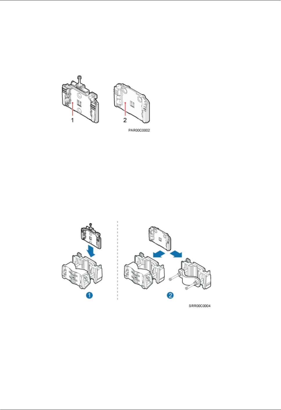
Figure 4-1 shows two kinds of attachment plates for a common RRU.
Figure 4-1 Attachment plate for a common RRU
(1) Attachment plate A for a common RRU
(2) Attachment plate B for a common RRU
An attachment plate for a common RRU is used during the replacement. Attachment
plate A for a common RRU can only be installed together with mounting kit A for a
common RRU, and attachment plate B for a common RRU can be installed together with
mounting kit A or B for a common RRU, as shown in Figure 4-2.
Figure 4-2 Scenarios where an attachment plate for a common RRU is installed together
with a mounting kit for a common RRU
(1) Scenario of attachment plate A for a
common RRU
(2) Scenarios of attachment plate B for a
common RRU
Procedure
Step 1 Wear ESD gloves.
RRU
Hardware Maintenance Guide
4 Replacing an RRU
Issue 16 (2015-03-23)
Huawei Proprietary and Confidential
Copyright © Huawei Technologies Co., Ltd.
17
Take proper ESD protection measures, for example, wear ESD gloves, to prevent electrostatic
damage to the boards, modules, or other electronic components.
Step 2 Use an M4 Phillips screwdriver to loosen the screws on the cover plate of the RRU cabling
cavity. Then open the cover plate.
Pre-loosen all screws before loosening them. This way, the screws are not damaged, and the
maintenance cavity is easy to be opened.
Step 3 Record cable connections on the panel of a board to be replaced.
Step 4 Disconnect all cables from the cabling cavity and bottom panel in the sequence of power
cables first and ground cabes at last.
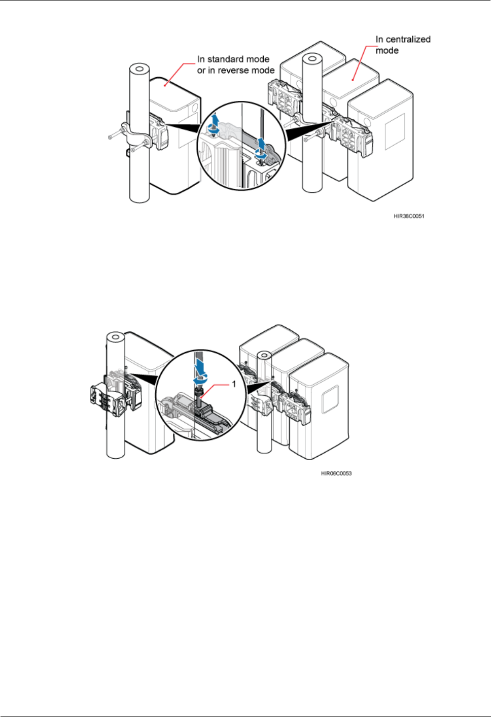
Step 5 Use an M4 Phillips screwdriver to loosen the captive screws on the two hoist clamps of the
main bracket, as shown in Figure 4-3 and Figure 4-4.
If an RRU is installed in centralized mode, the RRU can be removed without removing the two RRUs on
its right and left sides. The procedure is the same as that for removing a single RRU.
Replacing an RRU Using Mounting Kit A for a Common RRU
Figure 4-3 Loosening captive screws on the main bracket (1)
Replacing an RRU Using Mounting Kit B for a Common RRU
RRU
Hardware Maintenance Guide
4 Replacing an RRU
Issue 16 (2015-03-23)
Huawei Proprietary and Confidential
Copyright © Huawei Technologies Co., Ltd.
18
Figure 4-4 Loosening captive screws on the main bracket (2)
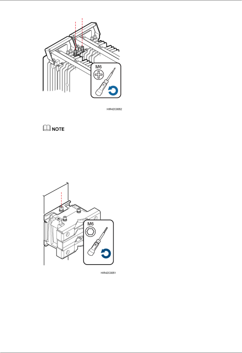
Step 6 Optional: When attachment plate A for a common RRU is used, use an M6 Phillips
screwdriver to loosen the screw only for removing the RRU on the attachment plate to loosen
the connection between the attachment plate and the main bracket, as shown in Figure 4-5.
Figure 4-5 Loosening the screw only for removing the RRU on the attachment plate
(1) Screw only for removing the RRU
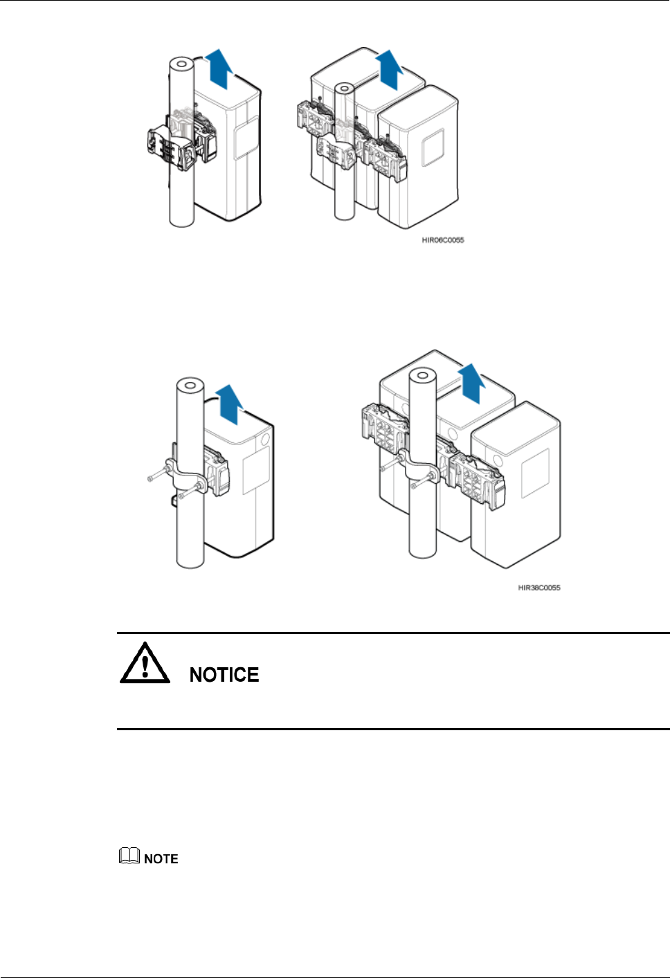
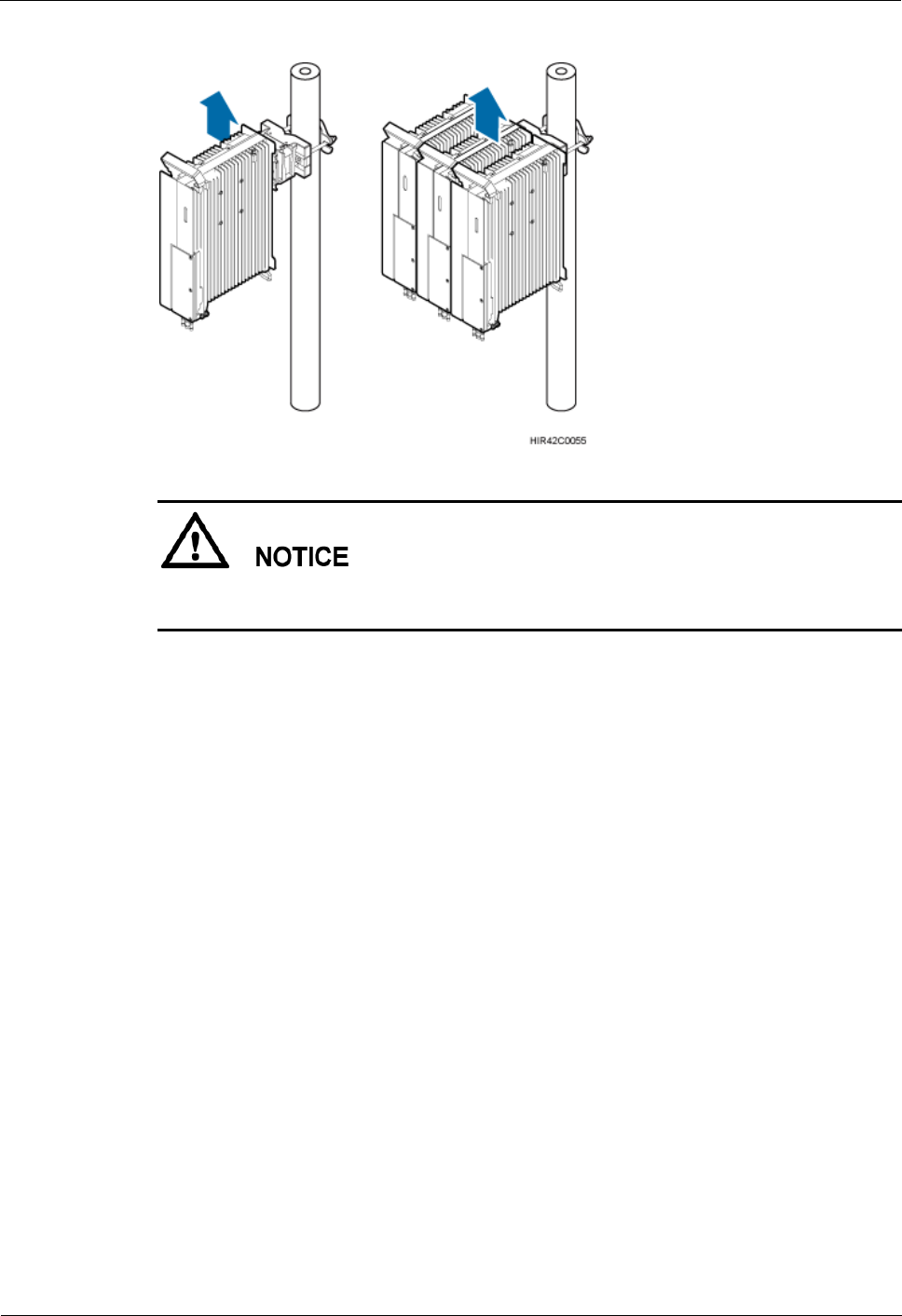
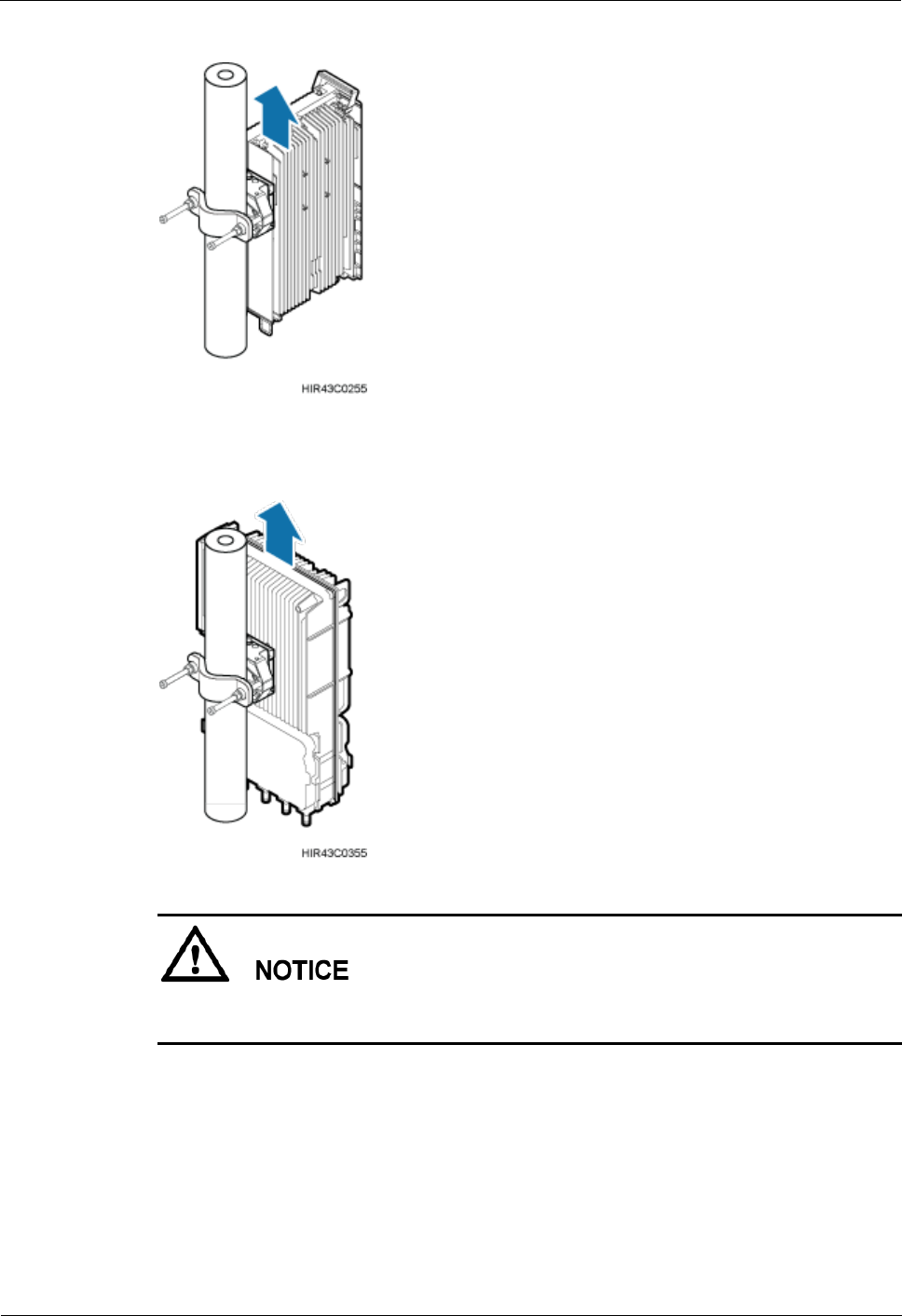
Step 7 Raise the bottom of the RRU to remove it, as shown in Figure 4-6 and Figure 4-7.
Replacing an RRU Using Mounting Kit A for a Common RRU
RRU
Hardware Maintenance Guide
4 Replacing an RRU
Issue 16 (2015-03-23)
Huawei Proprietary and Confidential
Copyright © Huawei Technologies Co., Ltd.
19
Figure 4-6 Raising the bottom of the RRU (1)
Replacing an RRU Using Mounting Kit B for a Common RRU
Figure 4-7 Raising the bottom of the RRU (2)
When removing the RRU, hold the RRU handle with one hand and raise the bottom of the
RRU with the other hand.
Step 8 Use an M4 torque screwdriver to tighten the captive screws on the two hoist clamps of the
main bracket to 1.4 N·m (12.39 lbf·in.).
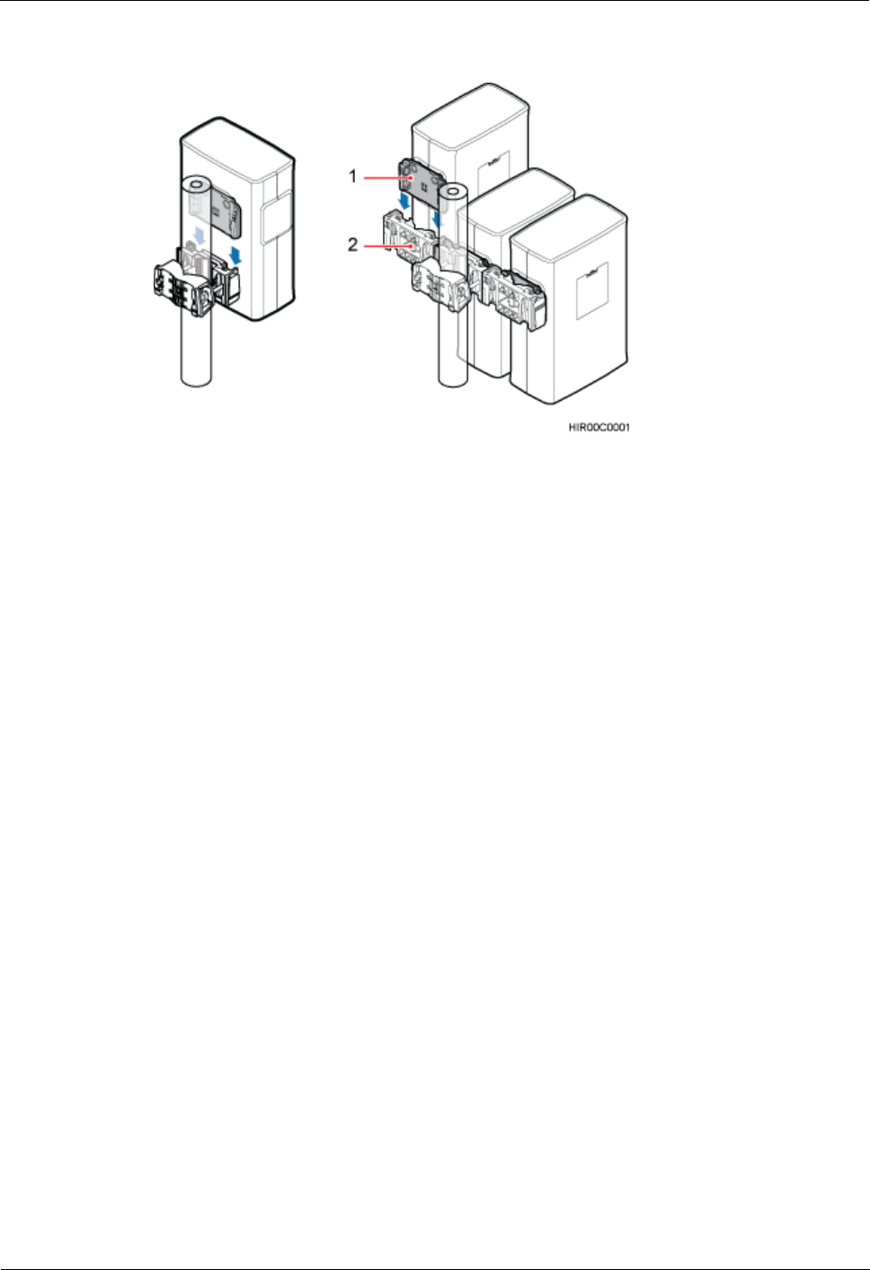
Step 9 When an RRU attachment plate matches its mounting kit, install a new RRU by referring to a
related RRU installation guide. Figure 4-8 shows the scenario where attachment plate B for a
common RRU is installed together with mounting kit A for a common RRU.
Attachment plate A for a common RRU matches mounting kit A for a common RRU, and attachment
plate B for a common RRU matches mounting kit B for a common RRU.
RRU
Hardware Maintenance Guide
4 Replacing an RRU
Issue 16 (2015-03-23)
Huawei Proprietary and Confidential
Copyright © Huawei Technologies Co., Ltd.
20
Figure 4-8 Scenario where attachment plate B for a common RRU is installed together with
mounting kit A for a common RRU
(1) Attachment plate B for a common RRU
(2) Mounting kit A for a common RRU
Step 10 Reconnect all required cables, waterproof the connectors on the RF jumpers, and ensure that
vacant cable troughs in the cabling cavity are blocked by waterproof blocks.
Step 11 Close the cover plate of the RRU cabling cavity. Then use an M4 torque screwdriver to
tighten the screws on the cover plate of the RRU cabling cavity.
----End
4.2.2 Replacing an RRU Using a Mounting Kit for a Blade RRU
This section describes the procedure and precautions for replacing an RRU using a mounting
kit for a blade RRU.
Prerequisites
The operations in 4.1 Preparations Before Replacement have been performed.
The following tools and materials are available: ESD gloves, an M5 Phillips screwdriver,
an M6 inner hexagon torque screwdriver, waterproof tape, and PVC insulation tape.
The number and type of RRUs to be replaced are confirmed, and new RRUs are
available.
Context
RRUs and attachment plates in this section are only for reference. The actual RRUs and
attachment plates may be different.
This section describes the procedure for replacing an RRU by reusing a mounting kit.
For how to replace an RRU by using a new mounting kit, see a related RRU installation
guide.
The RRU attachment plate varies with the RRU type before and after the replacement.
Figure 4-9 shows an attachment plate and a mounting kit for a blade RRU.
RRU
Hardware Maintenance Guide
4 Replacing an RRU
Issue 16 (2015-03-23)
Huawei Proprietary and Confidential
Copyright © Huawei Technologies Co., Ltd.
21
Figure 4-9 Attachment plate and mounting kit for a 12 L blade RRU
(1) Attachment plate for a blade RRU
Mounting kit for a blade RRU
Procedure
Step 1 Wear ESD gloves.
Take proper ESD protection measures, for example, wear ESD gloves, to prevent electrostatic
damage to the boards, modules, or electronic components.
Step 2 Use an M5 Phillips screwdriver to loosen the screws on the cover plate of the RRU cabling
cavity. Then open the cover plate.
Pre-loosen all screws before loosening them. This way, the screws are not damaged, and the
maintenance cavity is easy to be opened.
Step 3 Record all the cable connections on the panel of the module to be replaced.
Step 4 Disconnect all cables from the cabling cavity and bottom panel in the sequence of power
cables first and ground cabes at last.
Step 5 Optional: If an RRU installed in centralized mode is to be replaced, use an M6 Phillips
screwdriver to loosen the two screws on the metal sheet, and remove the metal sheet, as
shown in Figure 4-10.
RRU
Hardware Maintenance Guide
4 Replacing an RRU
Issue 16 (2015-03-23)
Huawei Proprietary and Confidential
Copyright © Huawei Technologies Co., Ltd.
22
Figure 4-10 Removing the metal sheet from an RRU installed in centralized mode
If an RRU is installed in centralized mode, the RRU can be removed without removing the two RRUs on
its right and left sides. The procedure is the same as that for removing a single RRU.
Step 6 Use an inner hexagon torque screwdriver to loosen captive screws on the attachment plate for
the RRU and on the top holes of the main bracket, as shown in Figure 4-11. Then raise the
bottom of the RRU to remove it, as shown in Figure 4-12.
Figure 4-11 Loosening captive screws on the attachment plate
RRU
Hardware Maintenance Guide
4 Replacing an RRU
Issue 16 (2015-03-23)
Huawei Proprietary and Confidential
Copyright © Huawei Technologies Co., Ltd.
23
Figure 4-12 Raising the bottom of the RRU
When removing the RRU, hold the RRU handle with one hand and raise the bottom of the
RRU with the other hand.
Step 7 Install a new RRU. For details, see RRU Installation Guide.
Step 8 Reconnect all required cables, waterproof the connector on the RF jumper, and verify that
vacant cable troughs in the cabling cavity are equipped by waterproof blocks.
Step 9 Close the cover plate of the RRU cabling cavity. Then use an M5 torque screwdriver to
tighten the screws on the cover plate of the RRU cabling cavity.
----End
4.3 Replacing an RRU Using Non-assembled Mounting
Kits
This section describes procedures and precautions for replacing an RRU using non-assembled
mounting kits.
Prerequisites
Preparations before powering off and replacing the RRU have been complete.
The following tools and materials are available: ESD gloves, M4 phillips screwdriver,
M6 hex screwdriver, M10 torque wrench, waterproof tape, and PVC insulation tape.
The quantity of faulty RRU modules has been determined, and the same quantity of new
RRU modules are ready.
RRU
Hardware Maintenance Guide
4 Replacing an RRU
Issue 16 (2015-03-23)
Huawei Proprietary and Confidential
Copyright © Huawei Technologies Co., Ltd.
24
Context
The RRUs and conversion brackets are only for reference.
The following figures use the blade RRU and non-blade RRU as an example to illustrate
how to replace the RRU. Specific appearances are subject to site conditions.
Figure 4-13 shows the appearance of non-assembled mounting kits.
Figure 4-13 Appearance of non-assembled mounting kits
Procedure
Step 1 Wear a pair of ESD gloves.
Step 2 Use an M4 phillips screwdriver for a non-blade RRU or an M5 phillips screwdriver for a
blade RRU to loosen the screws on the cover plate of the cabling cavity and open the RRU
cabling cavity.
Before loosening a screw, pre-loosen all screws. If the screws are damaged, it is difficult to
open the maintenance cavity.
Step 3 Record the position of the RRU cabling cavity and all cable connections at the bottom of the
RRU.
Step 4 Remove all cables in the RRU cabling cavity and at the RRU bottom in the sequence of power
cables first and ground cables at last.
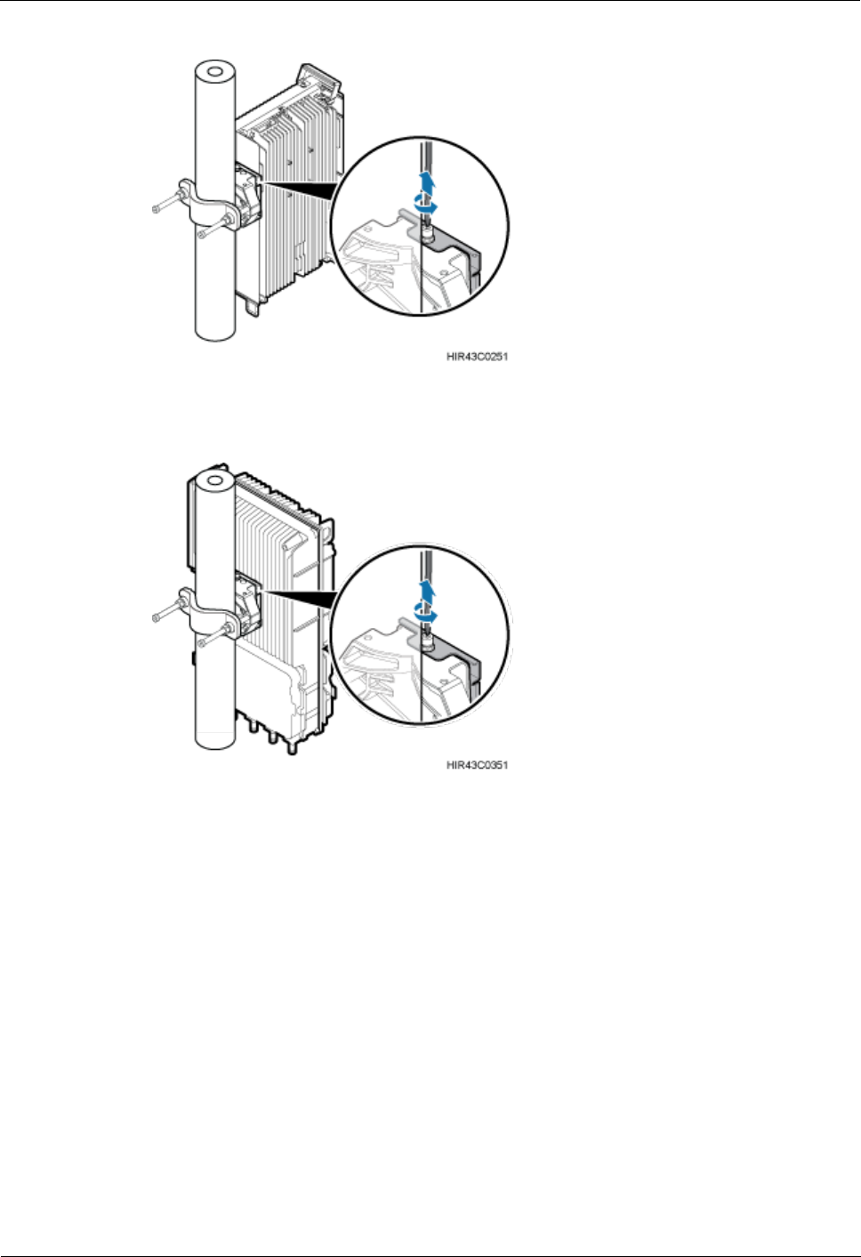
Step 5 Use an M6 hex screwdriver to loosen the captive screw on the holes on the top of the RRU
conversion bracket and main bracket, as shown in Figure 4-14 for the blade RRU and Figure
4-15 for the non-blade RRU.
RRU
Hardware Maintenance Guide
4 Replacing an RRU
Issue 16 (2015-03-23)
Huawei Proprietary and Confidential
Copyright © Huawei Technologies Co., Ltd.
25
Figure 4-14 Loosening screws on the conversion bracket (blade RRU)
Figure 4-15 Loosening screws on the conversion bracket (non-blade RRU)
Step 6 Hold the RRU upwards to remove it from the attachment plate, as shown in Figure 4-16 for
the blade RRU and Figure 4-17 for the non-blade RRU.
RRU
Hardware Maintenance Guide
4 Replacing an RRU
Issue 16 (2015-03-23)
Huawei Proprietary and Confidential
Copyright © Huawei Technologies Co., Ltd.
26
Figure 4-16 Holding the RRU upwards (blade RRU)
Figure 4-17 Holding the RRU upwards (non-blade RRU)
When removing the RRU, hold the RRU hander with one hand and hold the RRU upwards
with the other hand.
Step 7 Dispose of the removed RRU module properly.
Step 8 Install the new RRU and connect required cables by seeing the related RRU installation guide.
Ensure that vacant cable troughs in the cabling cavity are equipped by waterproof blocks and
RF cables are waterproofed.
----End

RRU
Hardware Maintenance Guide
4 Replacing an RRU
Issue 16 (2015-03-23)
Huawei Proprietary and Confidential
Copyright © Huawei Technologies Co., Ltd.
27
4.4 Replacing a Non-Blade RRU with a Blade RRU
This section describes the procedure and precautions for replacing a non-blade RRU with a
blade RRU.
Prerequisites
The operations in 4.1 Preparations Before Replacement have been performed.
The following tools and materials are available: ESD gloves, Phillips screwdrivers (M3
to M6), an M6 inner hexagon torque screwdriver, waterproof tape, and PVC insulation
tape.
The number and type of RRUs to be replaced are confirmed, and new RRUs are
available.
Context
RRUs and attachment plates in this section are only for reference. The actual RRUs and
attachment plates may be different.
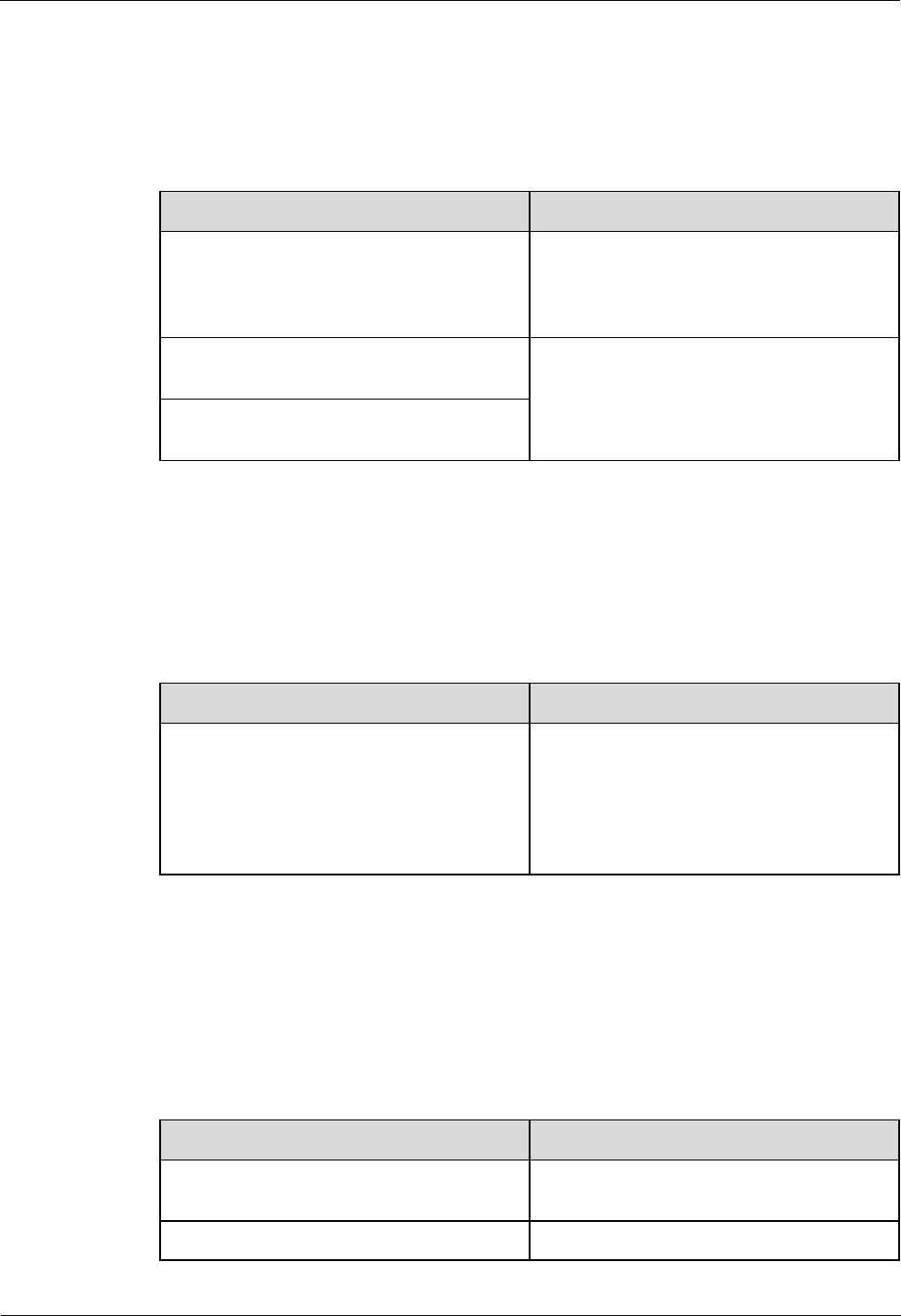
Table 4-1 shows the installation of the mounting kits and conversion bracket when
non-blade RRUs are assembled. When non-blade RRUs are not assembled, the mounting
kits and conversion bracket for blade RRUs are required for assist subsequent capacity
expansion, as shown in Table 4-1.
Table 4-1 Mounting kits and conversion bracket used for replacing non-blade RRUs with blade
RRUs
Replacement
Scenario
Position of the
RRU to be
Replaced
Mounting Kit
Reused or Not
Conversion
Bracket Reused or
Not
Non-blade RRUs are
assembled.
Middle
Reused
(Recommended)
Reused
For details about
how to install blade
RRUs, see
(Recommended)
Method 1: Reuse the
conversion bracket
Reused
Not reused
For details about
how to install blade
RRUs, see Method
2: The conversion
bracket is not reused
At bot sides
Not reused
Not reused
For details about
how to install blade
RRUs, see Replace
the RRUs at the two
sides
RRU
Hardware Maintenance Guide
4 Replacing an RRU
Issue 16 (2015-03-23)
Huawei Proprietary and Confidential
Copyright © Huawei Technologies Co., Ltd.
28
Replacement
Scenario
Position of the
RRU to be
Replaced
Mounting Kit
Reused or Not
Conversion
Bracket Reused or
Not
Non-blade RRUs are
not assembled.
-
Not reused
Not reused
This section describes the procedure for replacing an RRU by reusing a mounting kit.
For how to replace an RRU by using a new mounting kit, see a related RRU installation
guide.
After the replacement, an attachment plate for a blade RRU can be installed together
with mounting kit A or B for a common RRU, as shown in Figure 4-18.
Figure 4-18 Scenario where an attachment plate for a blade RRU can be installed together
with a mounting kit for a common RRU
(1) Attachment plate for a
blade RRU
(2) Mounting kit A for a
common RRU
(3) Mounting kit B for a
common RRU
The RRU mounting kit in the following figures is RRU mounting kit B.
Procedure
Step 1 Wear ESD gloves.
Take proper ESD protection measures, for example, wear ESD gloves, to prevent electrostatic
damage to the boards, modules, or electronic components.
Step 2 Remove cables for a faulty RRU and then remove RRU according to steps Step 1 to Step 8 in
4.2.1 Replacing an RRU Using a Mounting Kit for a Common RRU.
Step 3 Install the blade RRU.
RRU
Hardware Maintenance Guide
4 Replacing an RRU
Issue 16 (2015-03-23)
Huawei Proprietary and Confidential
Copyright © Huawei Technologies Co., Ltd.
29
Replace the RRU in the middle.
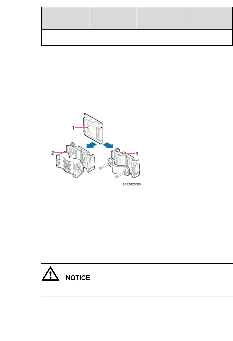
− (Recommended) Method 1: Reuse the conversion bracket.
1. Remove conversion brackets of the faulty RRU and blade RRU and install the
conversion bracket of the faulty RRU on the side of the blade RRU, as shown in Figure
4-19.
Figure 4-19 Reusing the conversion bracket
2. Install the blade RRU on the general main bracket, as shown in Figure 4-20.
RRU
Hardware Maintenance Guide
4 Replacing an RRU
Issue 16 (2015-03-23)
Huawei Proprietary and Confidential
Copyright © Huawei Technologies Co., Ltd.
30
Figure 4-20 Installing the blade RRU on the general RRU main bracket (conversion bracket
reused)
− Method 2: The conversion bracket is not reused.
Directly install the blade RRU on the general RRU main bracket, as shown in Figure
4-21.
Figure 4-21 Installing the blade RRU on the general RRU main bracket (conversion
bracket not reused)
Replace the RRUs at the two sides.
RRU
Hardware Maintenance Guide
4 Replacing an RRU
Issue 16 (2015-03-23)
Huawei Proprietary and Confidential
Copyright © Huawei Technologies Co., Ltd.
31
Remove the general mounting brackets of the faulty RRUs and install blade RRUs and
mounting kits by following the steps provided in the installation guide of the
corresponding RRU, as shown in Figure 4-22.
The following figure shows how to replace the RRU on the right.
Figure 4-22 Installing board RRUs (replacing RRUs at two sides)
Step 4 Install all cables for the blade RRU by referring to the section "Installing RRU Cables" in a
related RRU installation guide.
Step 5 Waterproof the ports for the RRU RF jumper by referring to the section "Installing an RRU
RF Jumper" in a related RRU installation guide.
Step 6 Waterproof the ports for the alarm cable by referring to Figure 4-23.
RRU
Hardware Maintenance Guide
4 Replacing an RRU
Issue 16 (2015-03-23)
Huawei Proprietary and Confidential
Copyright © Huawei Technologies Co., Ltd.
32
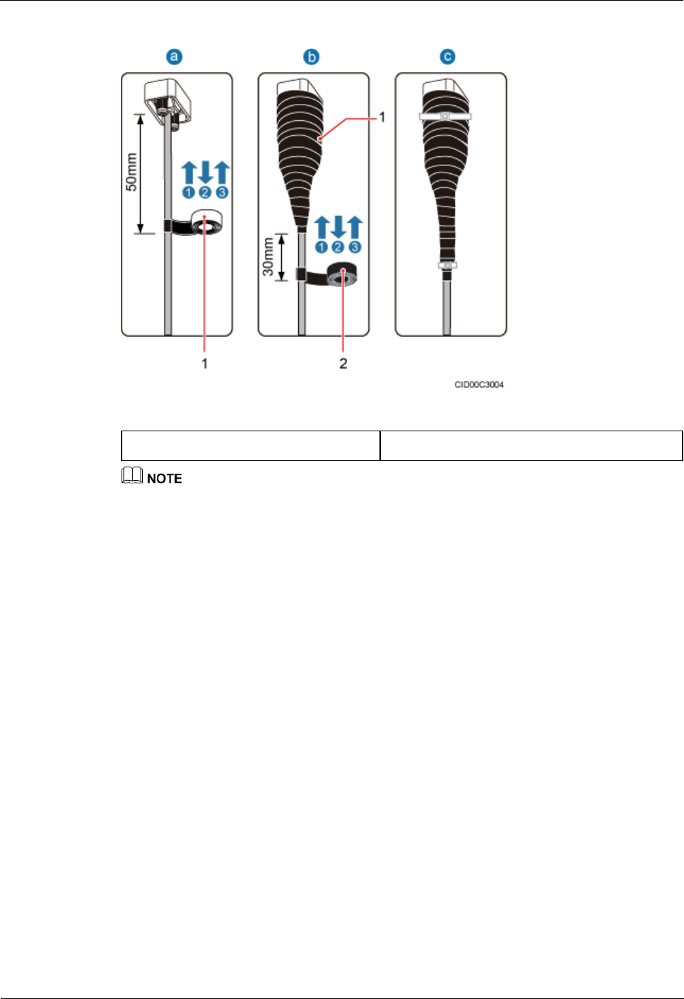
Figure 4-23 Waterproofing a connector of the alarm cable
(1) Waterproof tape
(2) PVC insulation tape
Before the replacement, ports for the alarm cables of a common RRU are positioned in the RRU
cabling cavity. After the replacement, ports for the alarm cables of a blade RRU are positioned at the
bottom of the RRU, and the ports need to be waterproofed.
Before wrapping waterproof tape, stretch the tape evenly until the length of the tape is twice its
original length.
Do not stretch the PVC insulation tape when wrapping it.
Wrap each layer of tape around the connector tightly and neatly, and ensure that each layer of tape
overlaps more than 50% of the lower layer.
Ensure that the adhesive surface of the tape overlaps the lower layer.
Leave an extra length of 3 mm (0.12 in.) to 5 mm (0.20 in.) when cutting off the extra part of the
cable ties.
1. Wrap three layers of waterproof tape on a connector, first from bottom up, then from top
down, and finally from bottom up. Start wrapping the connector at a position 50 mm
(1.97 in.) away from the bottom of the connector to the top of the connector, first from
bottom up, then from top down, and finally from bottom up. Cut off the redundant tape
after three layers are wrapped. Wrap each layer of tape around the connector tightly.
2. Wrap three layers of PVC insulation tape. Start the wrapping at a position 30 mm (1.18
in.) away below the bottom of the waterproof tape to the top of the connector, first from
bottom up, then from top down, and finally from bottom up. Cut off the redundant tape
after three layers are wrapped. Wrap each layer of tape around the connector tightly.
3. Bind cable ties to the cables at a position 3 mm (0.118 in.) to 5 mm (0.197 in.) away
from one end of the PVC insulation tape.
Step 7 Ensure that vacant cable troughs in the cabling cavity are blocked by waterproof blocks. Close
the cover plate of the RRU cabling cavity, and use an M5 torque screwdriver to tighten the
screws on the cover plate.
RRU
Hardware Maintenance Guide
4 Replacing an RRU
Issue 16 (2015-03-23)
Huawei Proprietary and Confidential
Copyright © Huawei Technologies Co., Ltd.
33
----End
4.5 Replacing Blade RRUs in the ICR and Adding Blade
RRUs to the ICR
This section describes procedures for replacing non-blade RRUs in the indoor centralized rack
(ICR) with blade RRUs and adding blade RRUs to the ICR.
Context
This document applies to 12 L blade RRU. The 18 L blade RRU does not support the
indoor centralized installation.
The attachment plates for installing a blade RRU in an ICR must support RRU
installation in a subrack. Figure 4-24 shows the exteriors of attachment plates for
installing an RRU in a subrack or installing a blade RRU in an ICR.
Figure 4-24 Attachment plates for installing an RRU in a subrack or installing a blade RRU
in an ICR
This section describes the procedure for maintaining an RRU in an ICR with a height of
10 U. The maintenance procedure is the same for RRUs in other ICRs, which do not
include the INS12 because it cannot be used for installing RRUs.
Procedure
Step 1 Wear ESD gloves.
Take proper ESD protection measures, for example, wear ESD gloves, to prevent electrostatic
damage to the boards, modules, or other electronic components.
Step 2 Remove the non-blade RRU to be replaced.
RRU
Hardware Maintenance Guide
4 Replacing an RRU
Issue 16 (2015-03-23)
Huawei Proprietary and Confidential
Copyright © Huawei Technologies Co., Ltd.
34
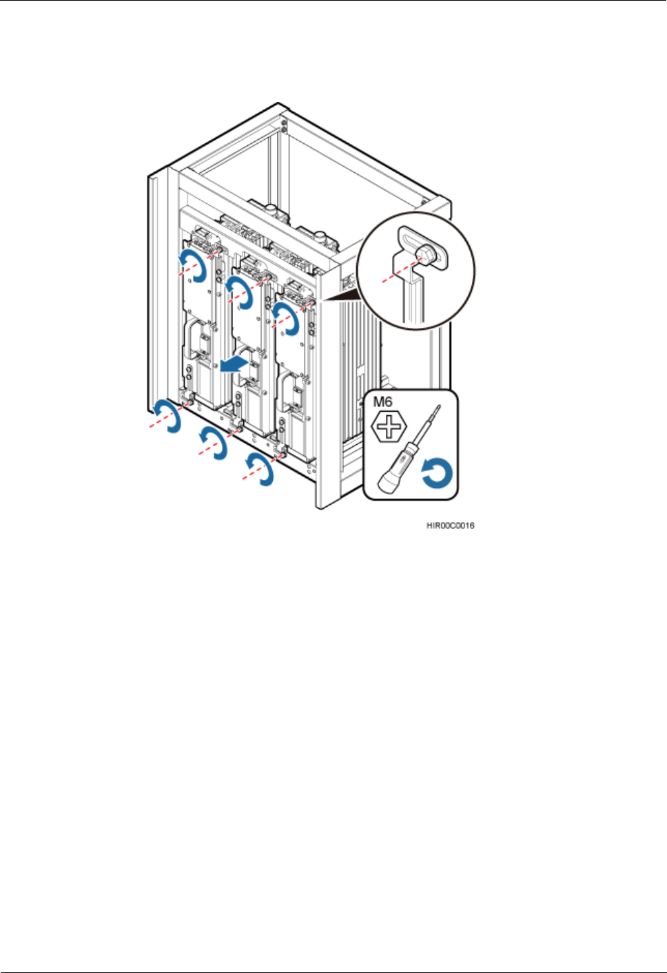
1. Use an M6 Phillips screwdriver to loosen the upper and lower installation plates on the
non-blade RRU to be replaced, as shown in Figure 4-25.
Figure 4-25 Loosing the upper and lower installation plates
2. Pull the RRU to be replaced out of the ICR.
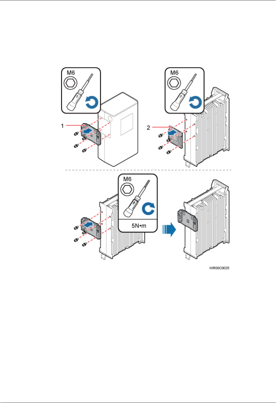
Step 3 Install the mounting brackets for the blade RRU.
1. Remove the attachment plate from the rear of the RRU, as shown in Figure 4-26.
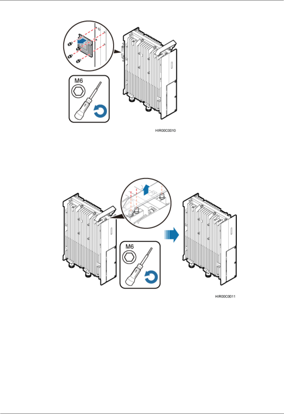
RRU
Hardware Maintenance Guide
4 Replacing an RRU
Issue 16 (2015-03-23)
Huawei Proprietary and Confidential
Copyright © Huawei Technologies Co., Ltd.
35
Figure 4-26 Removing the attachment plate from the rear of the RRU
2. Remove the handle from the RRU, as shown in Figure 4-27.
Figure 4-27 Removing the handle from the RRU
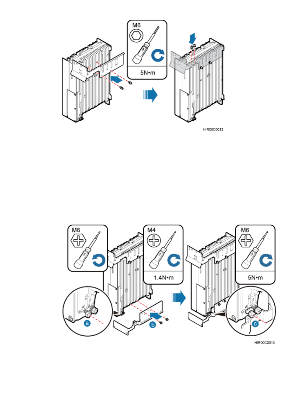
3. Take the upper and lower attachment plates for installing an RRU in a subrack or
installing a blade RRU in an ICR out of the packing case.
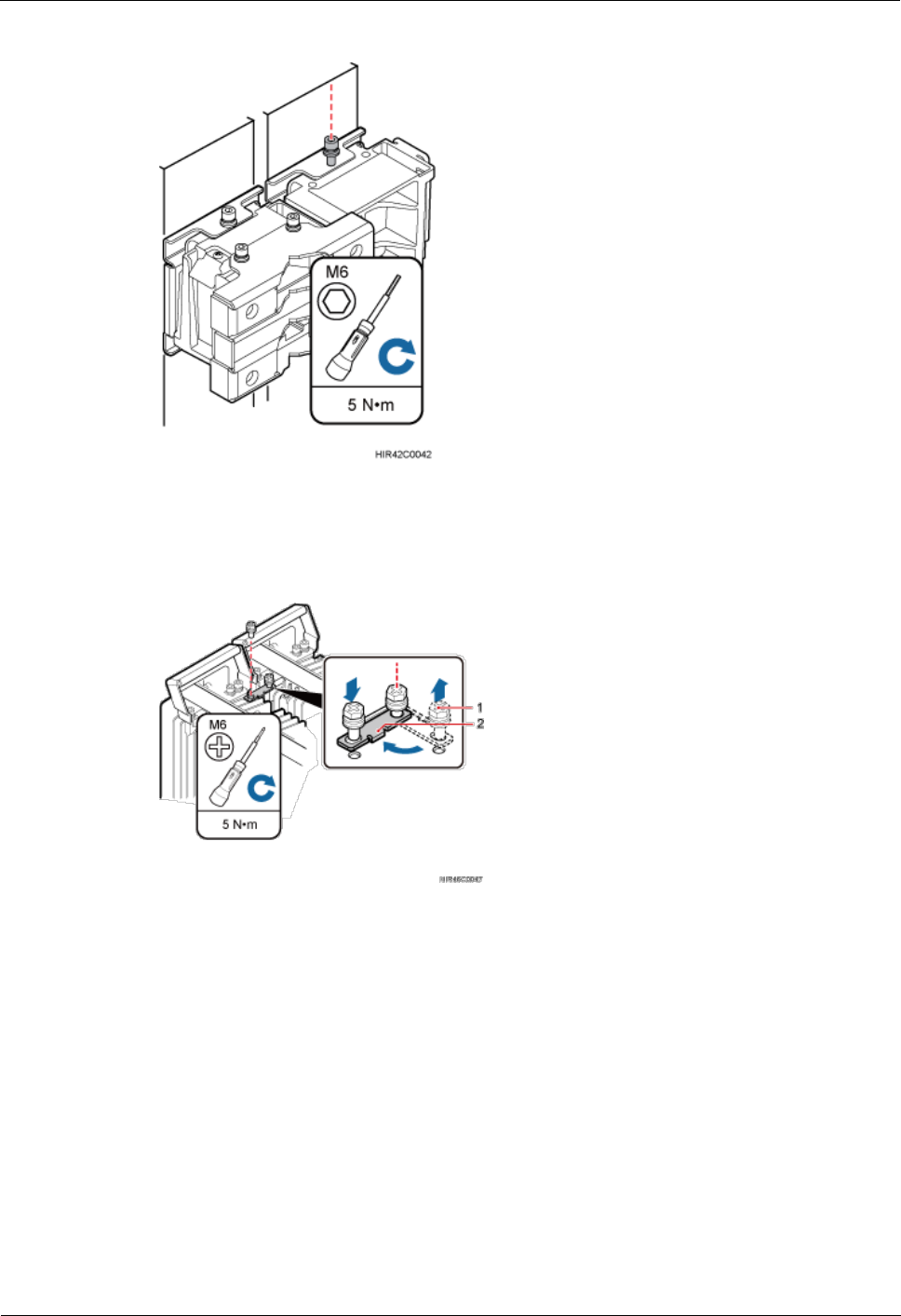
4. Install the upper attachment plate on the upper part of the RRU, and use an M6 torque
screwdriver to tighten the screws on the attachment plate to 5 N·m (44.25 lbf·in.), as
shown in Figure 4-28.
RRU
Hardware Maintenance Guide
4 Replacing an RRU
Issue 16 (2015-03-23)
Huawei Proprietary and Confidential
Copyright © Huawei Technologies Co., Ltd.
36
Figure 4-28 Installing the upper attachment plate on the upper part of the RRU
5. Install the lower attachment plate on the lower part of the RRU, as shown in Figure 4-29.
a. Use an M6 Phillips screwdriver to remove the ground screw from the left side of the
lower part of the RRU.
b. Use an M4 torque screwdriver to tighten the two screws on the lower attachment
plate to 1.4 N·m (812.39 lbf·in.).
c. Install the removed ground screw into the original ground hole to secure the lower
attachment plate.
Figure 4-29 Installing the lower attachment plate on the lower part of the RRU
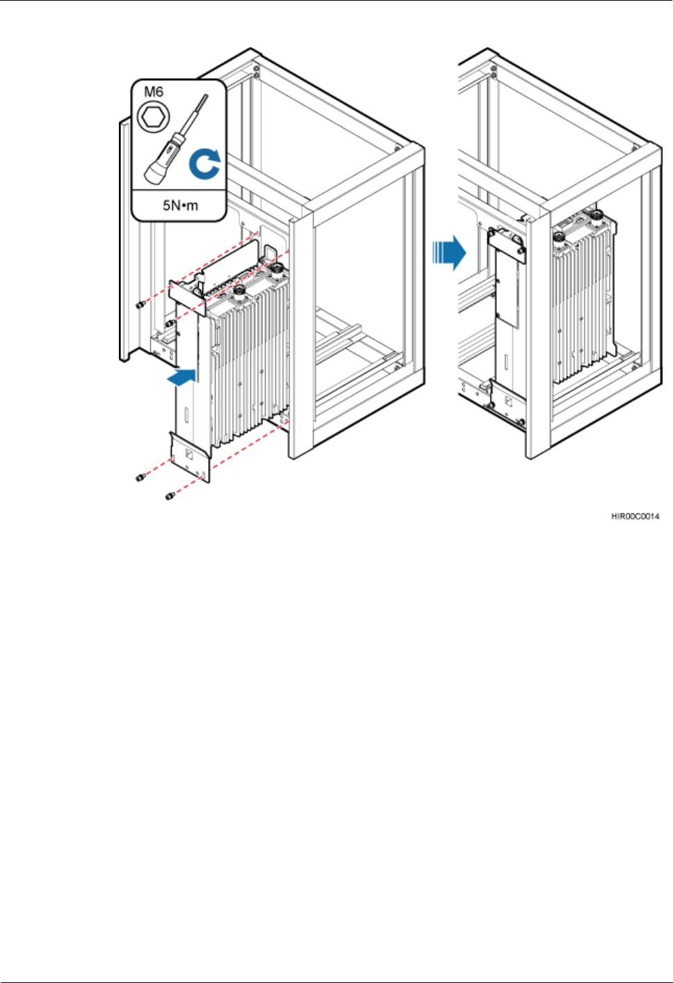
Step 4 Turn the RRU with upper and lower attachment plates upside down, insert the RRU into the
correct slot in an ICR, and tighten the four M6 screws on the RRU to 5 N·m (44.25 lbf·in.), as
shown in Figure 4-30.
RRU
Hardware Maintenance Guide
4 Replacing an RRU
Issue 16 (2015-03-23)
Huawei Proprietary and Confidential
Copyright © Huawei Technologies Co., Ltd.
37
Figure 4-30 Installing the RRU in an ICR
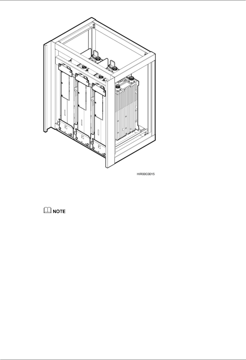
Step 5 Optional: Install the other two RRUs by referring to Step 3 and Step 4. An ICR can house a
maximum of three RRUs. Figure 4-31 shows an ICR housing three RRUs.
RRU
Hardware Maintenance Guide
4 Replacing an RRU
Issue 16 (2015-03-23)
Huawei Proprietary and Confidential
Copyright © Huawei Technologies Co., Ltd.
38
Figure 4-31 ICR housing three RRUs
Step 6 Reconnect all required cables for the new RRU, waterproof the connector on the RF jumper,
and ensure that vacant cable troughs in the cabling cavity are equipped by waterproof blocks.
For details about cable connections, see the blade RRU installation guide. Cables can be reused
according to onsite requirements.
Step 7 Close the cover plate of the RRU cabling cavity, and use an M5 torque screwdriver to tighten
the screws on the cover plate to 2 N·m (17.7 lbf·in.).
Step 8 Take off the ESD gloves, and pack up all the tools.
----End
Follow-up Procedure
If a blade RRU is used to replace a non-blade RRU, properly store the removed non-blade
RRU.
4.6 Operations After Replacement
This section describes operations to be performed after an RRU is replaced, including setting
the maximum output power locking, unblocking an RRU, powering on an RRU, and handling
a faulty RRU.

RRU
Hardware Maintenance Guide
4 Replacing an RRU
Issue 16 (2015-03-23)
Huawei Proprietary and Confidential
Copyright © Huawei Technologies Co., Ltd.
39
Prerequisites
An RRU has been replaced.
Procedure
Step 1 Power on the RRU according to the instructions in 3.1 Powering On an RRU.
Step 2 Check the operating status of the new RRU by observing the status of RRU indicators. When
the RRU is working properly, the RUN indicator is blinking (on for 1s and off for 1s), and the
ALM indicator is steady off.
Step 3 Optional: Set the maximum output power locking for TX channels of the RRU.
On the UMTS or LTE side, run the LOC RRUTC command to set the maximum output
power of the RRU. Run the RST BRD command to reset the RRU. Run the DSP
TXBRANCH command to check whether the maximum output power of each RRU is
set successfully.
On the GSM side, log in to the SMT. In the left pane of the Site Maintenance Terminal
System window, click Site. In the right pane of the window, double-click Lock RXU
Traffic Capability. In the displayed Lock RXU Traffic Capability window, click the
Config tab. On the displayed tab page, select the target RRU. Log in to the LMT and
reset the RRU so that the configuration data takes effect.
On the GSM side, log in to the LMT. Enter LOC BTSRXUTC in the Command Input
box and click Assist to set the maximum output power. Then, Click Exec. Run the RST
BTSBRD command with Reset Type set to SOFTWARE to reset the RRU so that the
configuration data takes effect.
If there is more than one RRU, perform the operation on each RRU.
If there is more than one RRU, reset each RRU.
If the configured maximum output power of the RRU exceeds its hardware capability, this
configuration is invalid and the maximum output power of the RRU is the maximum output power
supported by the RRU hardware.
Step 4 Instruct the network management system (M2000/U2000) administrator to unblock the RRU.
On the UMTS side, log in to the NodeB LMT and run the UBL BRD command to
unblock the RRU.
On the LTE side, log in to the eNodeB LMT and run the UBL BRD command to unblock
the RRU.
On the GSM side, log in to the BSC LMT and run the SET GTRXADMSTAT
command with the parameter ADMSTAT set to UNLOCK to unblock the carriers of the
RRU.
Step 5 Take off the ESD gloves, and pack up all the tools.
Step 6 Place the removed RRU into the ESD box or bag. Then, place the ESD box or bag into a
foam-padded carton or the packing box of the new RRU.
Step 7 Complete the fault form with detailed information about the replaced component.
Step 8 Contact the local Huawei office to handle the faulty component.
----End
RRU
Hardware Maintenance Guide
5 Replacing an Optical Module
Issue 16 (2015-03-23)
Huawei Proprietary and Confidential
Copyright © Huawei Technologies Co., Ltd.
40
5 Replacing an Optical Module
An optical module implements optical-electrical conversion, enabling optical transmission
between an RRU and other devices. You must disconnect optical fibers from an optical
module before replacing the optical module. Disconnecting the optical fibers interrupts the
transmission of CPRI signals.
Prerequisites
Confirm the type of a faulty optical module and do as follows:
− On the GSM side, run the DSP BTSOPTMODULE command on the BSC.
− On the UMTS side, if NodeB V200R013 or a version before is used, run the DSP
OPTMODULE command on the NodeB.
− On the UMTS side, if NodeB V200R014 or a later version is used, run the DSP SFP
command on the NodeB.
− On the LTE side, rRun the DSP SFP command on the eNodeB.
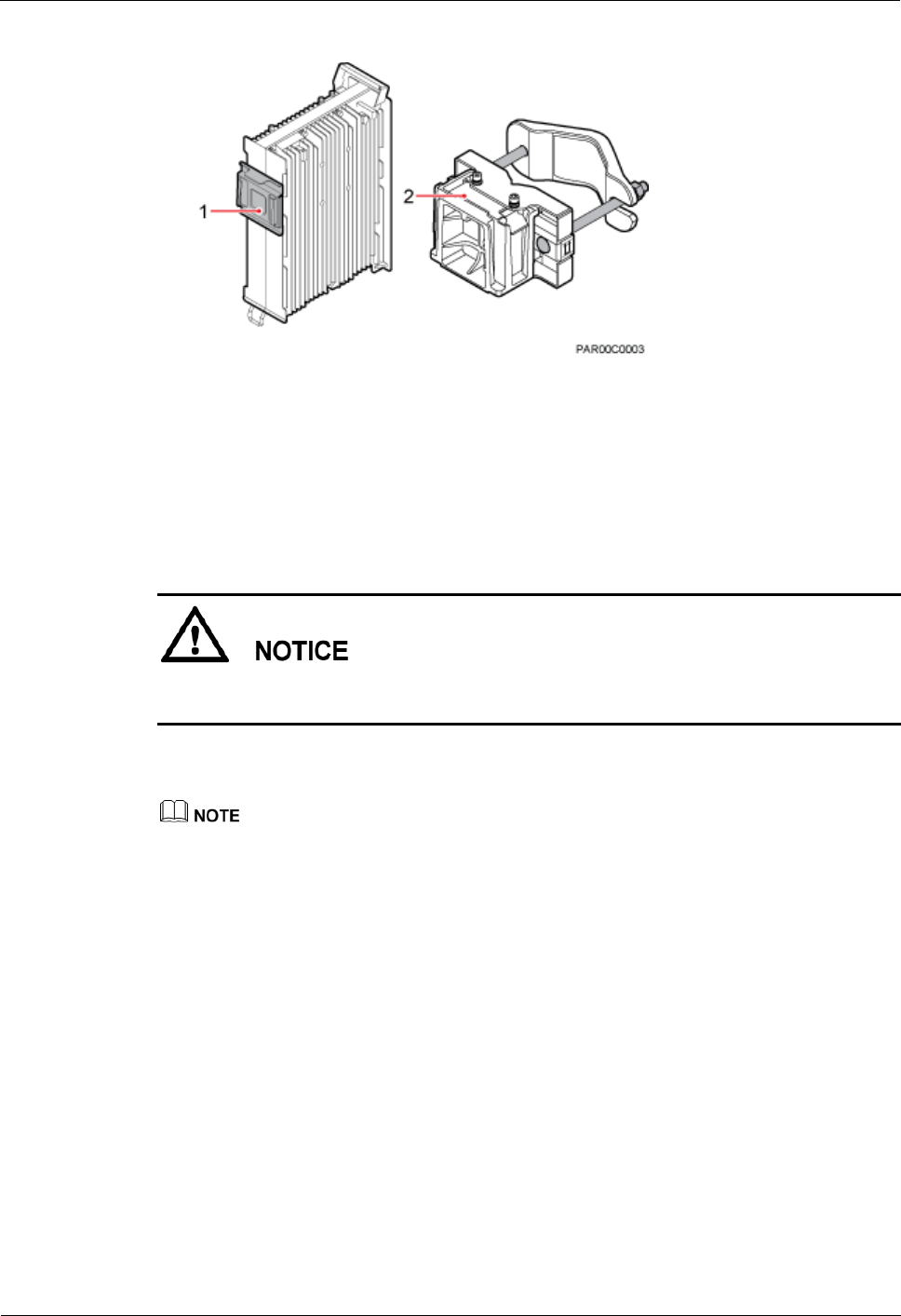
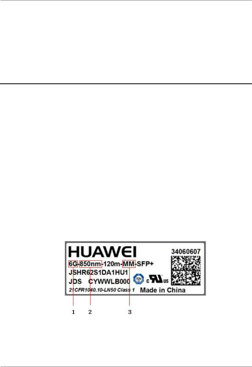
− Confirm the type of the faulty optical module according to the Rate, Wavelength,
and Transmission mode fields in the query result and obtain an optical module of the
same type. Figure 5-1 shows the label on the optical module.
Figure 5-1 Label on the optical module
(1) Peak rate
(2) Wavelength
(3) Transmission mode
RRU
Hardware Maintenance Guide
5 Replacing an Optical Module
Issue 16 (2015-03-23)
Huawei Proprietary and Confidential
Copyright © Huawei Technologies Co., Ltd.
41
− If the software version does not support query of the type of the optical module by
using an MML command, obtain all types of optical modules.
− If a fault in the optical module on the RRU side causes disconnection of the CPRI
link, the MML command to query the type of the fault cannot be used. In this case,
query the type of the corresponding optical module on the BBU side instead and
obtain a new optical module of the same type. For the detailed querying method, see
the DBS3900 Site Maintenance Guide.
The following tools and materials are available: ESD gloves, M4 Phillips screwdrivers,
and an ESD box or bag.
Context
Optical modules are inserted into CPRI ports on an RRU.
If the optical module, cable, or optical cable is removed and then connected to the same
CPRI port of the RRU, the optical module, cable, or optical cable is hot swappable.
If the optical module, cable, or optical cable is removed and then connected to a different
CPRI port of the RRU, the optical module, cable, or optical cable is still hot swappable,
but you need to perform either of the following operations to manually reset the RRU to
prevent service interruption.
− For a NodeB, eNodeB, and eGBTS, run the RST BRD command to reset the RRU.
− For a GBTS, run the RST BTSBRD command to reset the RRU.
It takes about five minutes to replace an optical module on the RRU, which involves
disconnecting optical fibers, removing the faulty optical module, inserting a new optical
module, reconnecting the optical fibers, and waiting for CPRI links to resume.
Procedure
Step 1 Wear ESD gloves.
Take proper ESD protection measures, for example, wear ESD gloves, to prevent electrostatic
damage to the boards, modules, or electronic components.
Step 2 Power off the RRU according to the instructions in 3.2 Powering Off an RRU.
Step 3 Loosen the screws on the cover plate of the RRU cabling cavity using an M4 Phillips
screwdriver, and then open the cover plate.
Step 4 Record the connections of the optical module and optical fibers.
Step 5 Press the latch on the optical fiber connector, and then remove the connector from the faulty
optical module.
Do not look into the optical fiber or optical module without eye protection after the optical
fiber is removed from the optical module.

RRU
Hardware Maintenance Guide
5 Replacing an Optical Module
Issue 16 (2015-03-23)
Huawei Proprietary and Confidential
Copyright © Huawei Technologies Co., Ltd.
42
Step 6 Lower the puller on the faulty optical module, and then pull the puller until the optical module
is removed from the RRU.
Step 7 Choose the optical module of the same type as the faulty optical module according to the label
on the module. Install the new optical module into the RRU.
The optical modules to be installed must match CPRI rates.
Step 8 Insert the optical fiber connector into the new optical module.
Step 9 Close the cabling cavity of the RRU and use an M4 Phillips screwdriver to tighten the screws
on the cover plate for the cabling cavity.
Step 10 Power on the RRU according to the instructions in 3.1 Powering On an RRU.
Step 11 Check the operating status of the new RRU by observing the status of RRU indicators. When
the RRU is working properly, the RUN indicator is blinking (on for 1s and off for 1s) and the
ALM indicator is steady off.
Step 12 Take off the ESD gloves, and pack up all the tools.
----End
Follow-up Procedure
Place the replaced optical module into the ESD box or bag. Then, place the ESD box or
bag into a foam-padded carton or the packing box of the new module.
Fill in the fault form with detailed information about the replaced module.
Contact the local Huawei office to handle the faulty optical module.
RRU
Hardware Maintenance Guide
6 Adding RRUs
Issue 16 (2015-03-23)
Huawei Proprietary and Confidential
Copyright © Huawei Technologies Co., Ltd.
43
6 Adding RRUs
This chapter describes the procedure and precautions for adding RRUs with different exteriors
on a pole.
Prerequisites
The hoist clamp of the main bracket is secured properly.
Do not stand the RRU upright because the RF ports cannot support the weight of the RRU.
Place a foam pad or cardboard under the RRU to protect the RRU housing from damage
during the installation.
Context
A maximum of two, three, four, or six RRUs can be installed on a pole. When four or
more than four RRUs are added on a pole, the RRUs are installed vertically at different
levels and in different directions, and the length of the pole must be greater than or equal
to 1.5 m (4.92 ft).
Install RRUs with the same exterior by referring to the section "Installing Three or More
RRUs"in a related RRU installation guide.
This chapter describes the procedure for adding RRUs with different exteriors and uses
the procedure for adding five blade RRUs to a non-blade RRU in a live network as an
example.
Procedure
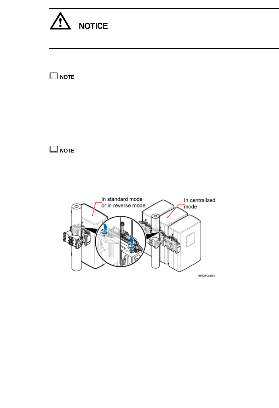
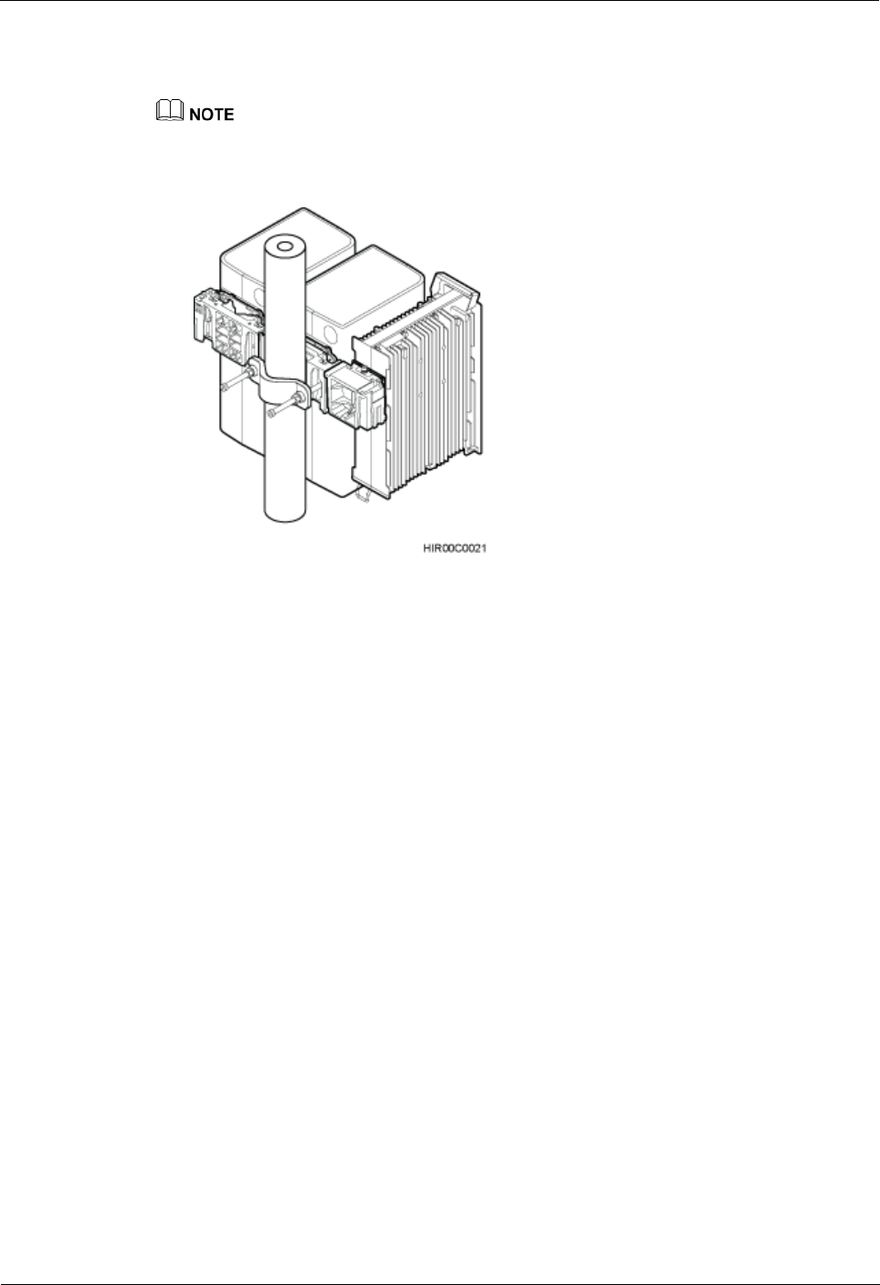
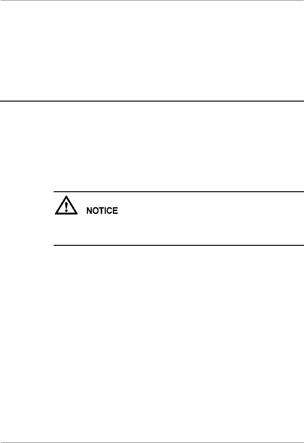
Step 1 Optional: When the non-blade RRUs are installed in standard mode in the live network,
change the standard mode to the side-mounted mode, as shown in Figure 6-1.
1. Instruct the network management system (M2000/U2000) administrator to block the
RRUs.
On the UMTS side, log in to the LMT and run the BLK BRD command to block the
RRUs.
On the LTE side, log in to the LMT and run the BLK BRD command to block the RRUs.
RRU
Hardware Maintenance Guide
6 Adding RRUs
Issue 16 (2015-03-23)
Huawei Proprietary and Confidential
Copyright © Huawei Technologies Co., Ltd.
44
On the GSM side, log in to the BSC LMT and run the SET GTRXADMSTAT
command with the parameter ADMSTAT set to LOCK to block the carriers of the
RRUs.
2. Power off the RRUs according to the instructions in 3.2 Powering Off an RRU.
3. Remove the RRUs and their cables according to steps Step 1 to Step 8 in 4.2.1 Replacing
an RRU Using a Mounting Kit for a Common RRU.
4. Remove the attachment plate at the rear of the RRU and install it on one side of the RRU.
Then install the RRU by referring to the section "Installing Three or More RRUs"in a
related RRU installation guide.
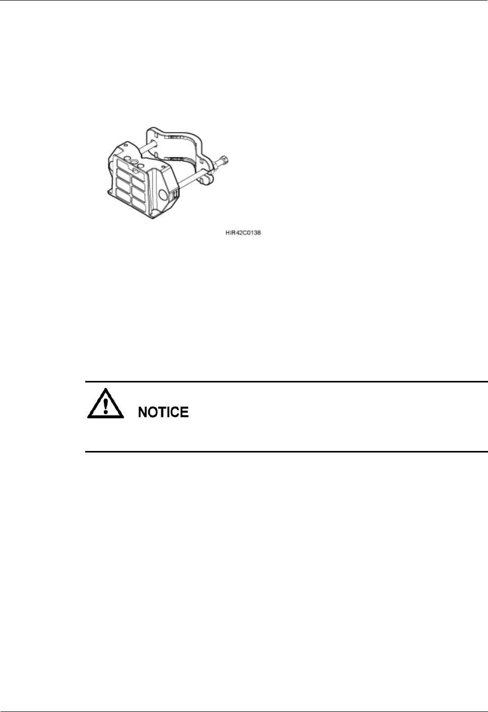
Figure 6-1 Changing a non-blade RRU installation mode to side-mounted mode
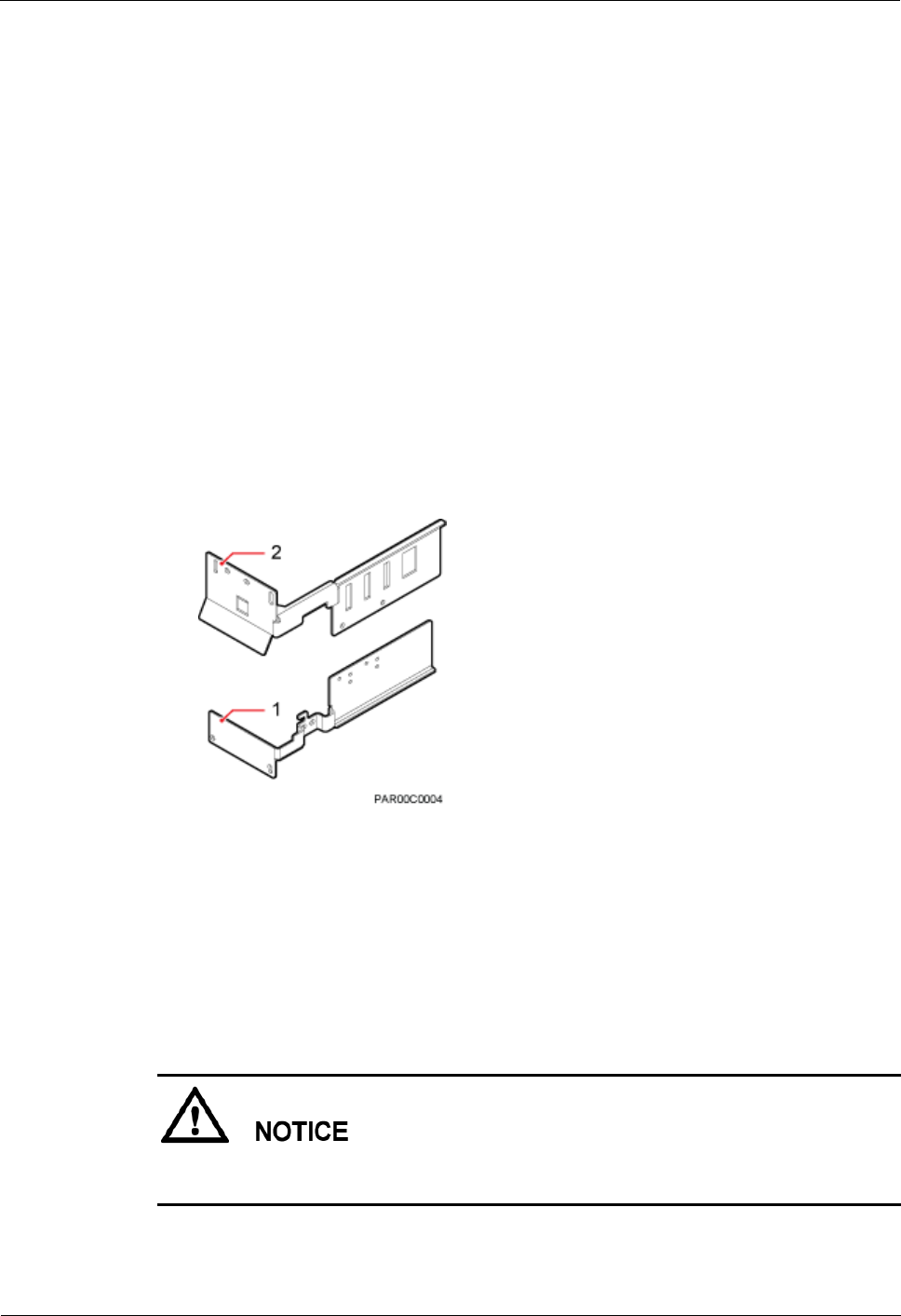
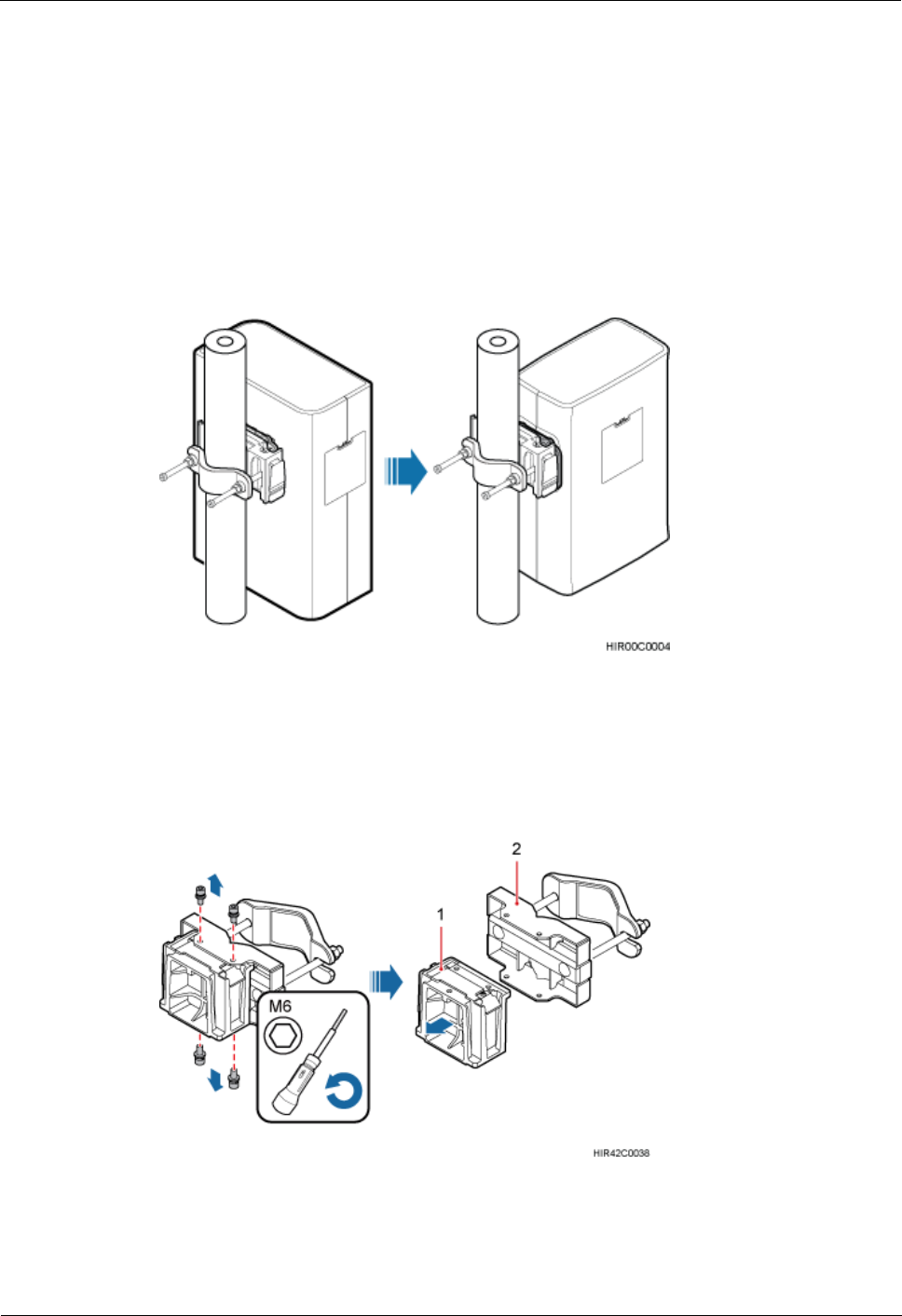
Step 2 Use an M6 inner hexagon screwdriver to remove the four inner hexagon screws from the pole
installation bracket, and remove the main bracket for a blade RRU from the pole installation
bracket, as shown in Figure 6-2.
Figure 6-2 Removing the main bracket for a blade RRU
(1) Main bracket for a blade RRU
(2) Pole installation bracket for a blade RRU
RRU
Hardware Maintenance Guide
6 Adding RRUs
Issue 16 (2015-03-23)
Huawei Proprietary and Confidential
Copyright © Huawei Technologies Co., Ltd.
45
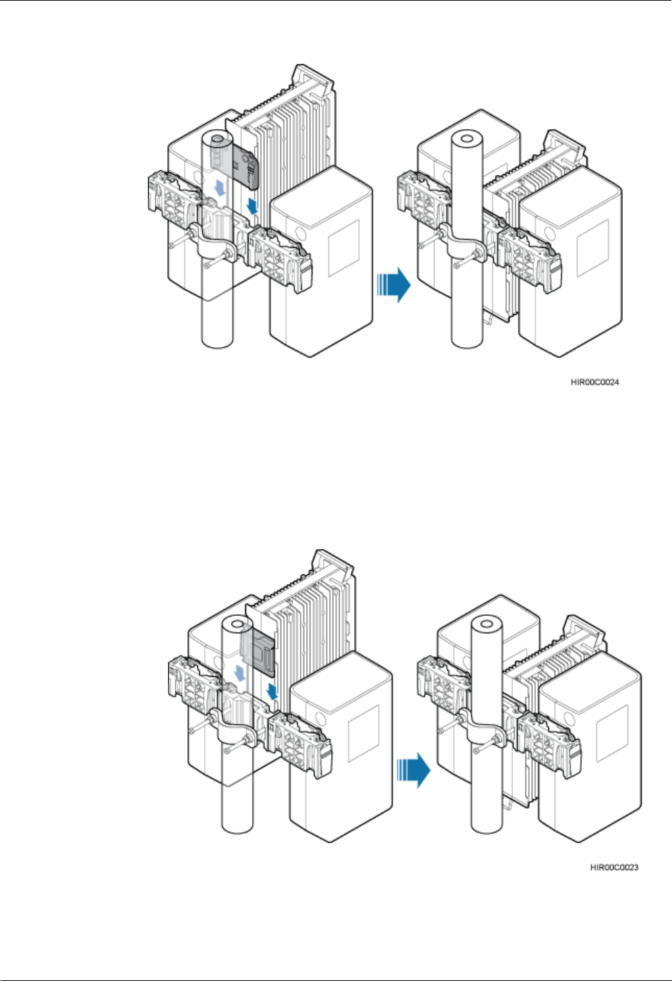
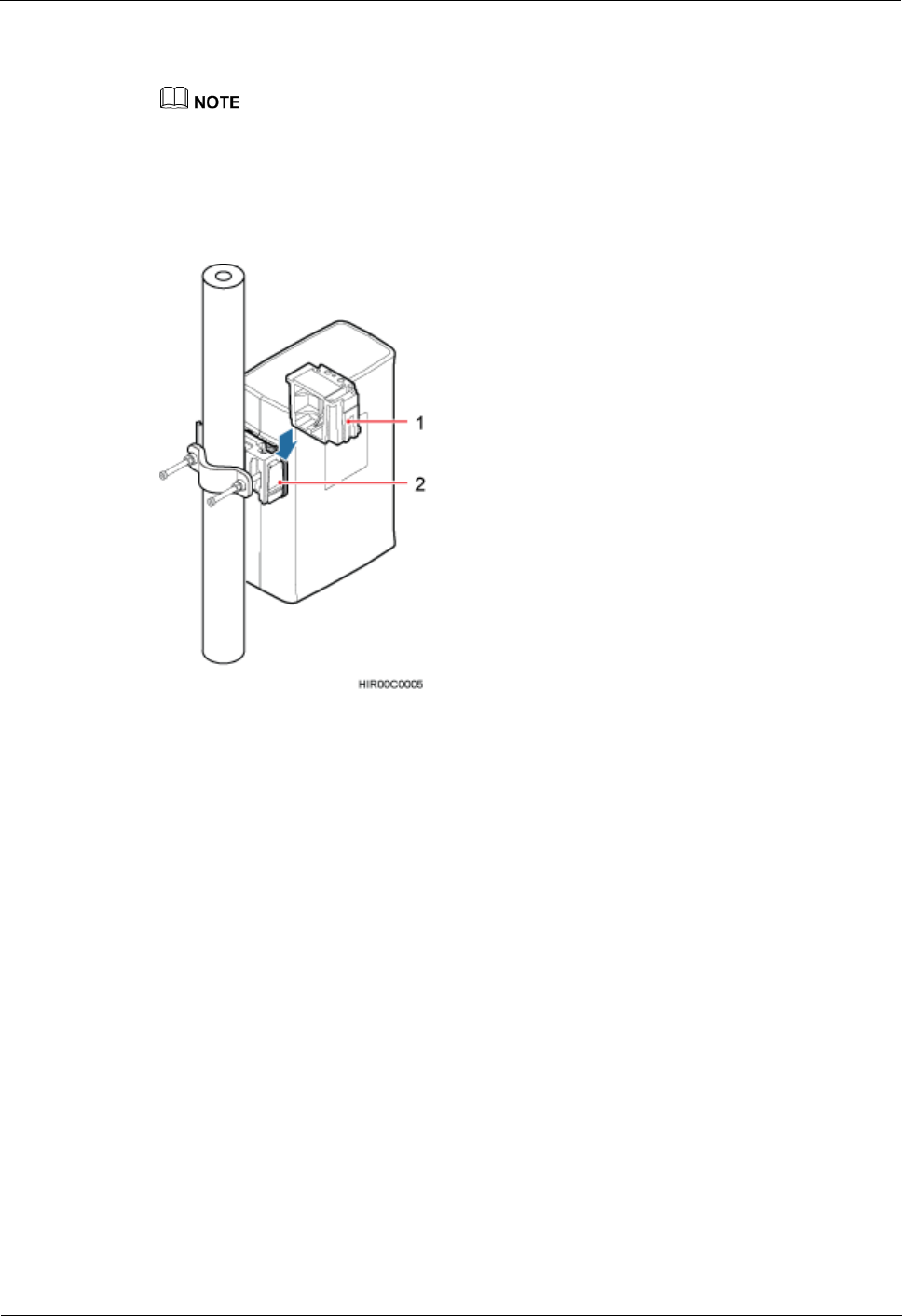
Step 3 Install the main bracket for a blade RRU on the main bracket of the mounting kit for a
common RRU, as shown in Figure 6-3.
The auxiliary bracket in the following figure is only for reference. The actual auxiliary bracket may
be different.
The opening ends of U-shaped slots on both sides of the main bracket for a blade RRU face
downwards.
Figure 6-3 Installing the main bracket for a blade RRU
(1) Main bracket for a blade RRU
(2) Main bracket for a common RRU
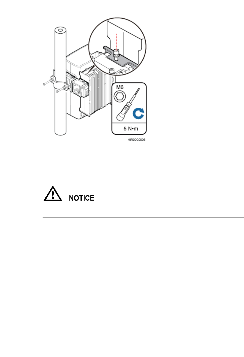
Step 4 Attach a blade RRU to the main bracket for a blade RRU, and then use an inner hexagon
torque screwdriver to tighten the captive screws into the holes of the attachment plate and
main bracket to 5 N·m (44.25 lbf·in.), as shown in Figure 6-4.
RRU
Hardware Maintenance Guide
6 Adding RRUs
Issue 16 (2015-03-23)
Huawei Proprietary and Confidential
Copyright © Huawei Technologies Co., Ltd.
46
Figure 6-4 Attaching a blade RRU
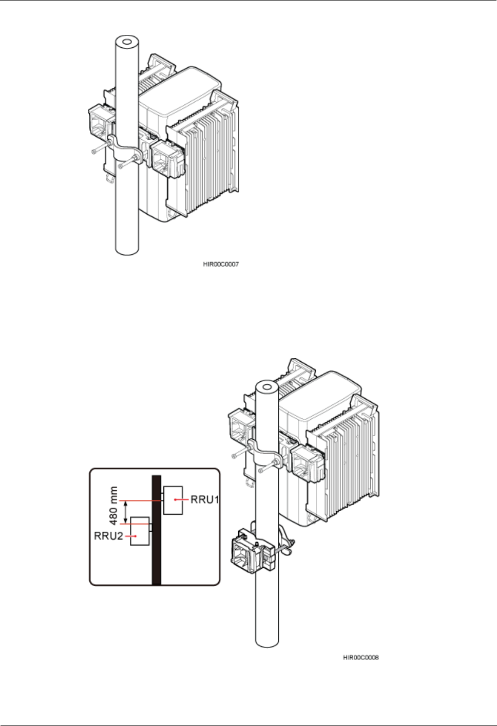
Step 5 Repeat steps Step 2 to Step 4 to install a main bracket for a blade RRU or a blade RRU on the
other side of the main bracket for a common RRU, as shown in Figure 6-5.
The opening ends of U-shaped slots on both sides of the main bracket for a blade RRU face
downwards.
RRU
Hardware Maintenance Guide
6 Adding RRUs
Issue 16 (2015-03-23)
Huawei Proprietary and Confidential
Copyright © Huawei Technologies Co., Ltd.
47
Figure 6-5 Installing the third RRU on the third main bracket
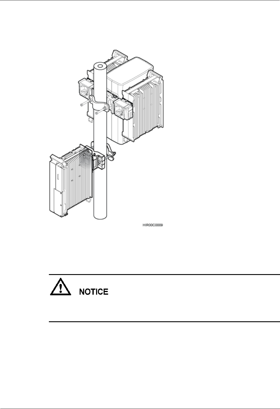
Step 6 Install the second RRU mounting kit at a position of at least 480 mm (18.90 in.) away from
the top or bottom of the first RRU mounting kit, as shown in Figure 6-6.
Figure 6-6 Installing the second mounting kit for a blade RRU
RRU
Hardware Maintenance Guide
6 Adding RRUs
Issue 16 (2015-03-23)
Huawei Proprietary and Confidential
Copyright © Huawei Technologies Co., Ltd.
48
Step 7 Attach a blade RRU to the fourth main bracket, and then use an inner hexagon torque
screwdriver to tighten the captive screws into the holes of the attachment plate and main
bracket to 5 N·m (44.25 lbf·in.), as shown in Figure 6-7.
Figure 6-7 Installing a blade RRU on the fourth main bracket
Step 8 Install blade RRUs on both sides of the blade RRU according to the instructions in the section
"Installing Three or More RRUs" in a related blade RRU installation guide.
After installing each RRU on its main bracket, use an inner hexagon torque screwdriver to
tighten the captive screw into the holes of the attachment plate and main bracket to 5 N·m
(44.25 lbf·in.), as shown in Figure 6-8.
RRU
Hardware Maintenance Guide
6 Adding RRUs
Issue 16 (2015-03-23)
Huawei Proprietary and Confidential
Copyright © Huawei Technologies Co., Ltd.
49
Figure 6-8 Tightening the captive screws into the holes
Step 9 Install a metal sheet for two neighboring RRUs, as shown in Figure 6-9.
Figure 6-9 Installing a metal sheet
(1) Screw
(2) Metal sheet
1. Use an M6 Phillips screwdriver to loosen the screw on the metal sheet farther from the
handle of the first RRU and remove the screw.
2. Use an M6 Phillips screwdriver to slightly loosen the screw on the metal sheet closer to
handle of the first RRU and move the metal sheet out. Then align the holes in the metal
sheet with the holes at the top of the second RRU.
3. Insert the removed screws into the holes at the top of the second RRU and use an M6
torque screwdriver to tighten the screws to 5 N·m (44.25 lbf·in.).
Step 10 Install RRU cables and close the RRU cabling cavity according to the instructions in related
RRU installation guides.
Step 11 Power off the RRU according to the instructions in 3.1 Powering On an RRU.

RRU
Hardware Maintenance Guide
6 Adding RRUs
Issue 16 (2015-03-23)
Huawei Proprietary and Confidential
Copyright © Huawei Technologies Co., Ltd.
50
Step 12 Check the operating status of the new RRU by observing the status of RRU indicators. When
the RRU is working properly, the RUN indicator is blinking (on for 1s and off for 1s), and the
ALM indicator is steady off.
----End