Huawei Technologies RRU3642 Multi-mode Multi-carriers Remote Radio Unit User Manual
Huawei Technologies Co.,Ltd Multi-mode Multi-carriers Remote Radio Unit
UserManual.wiki
>
Huawei Technologies
>
RRU3642 User Manual
Installation Guide
Navigation menu
Upload a User Manual
Namespaces
Wiki Guide
HTML
PDF
Info
Views
User Manual
Discussion / Help
Navigation
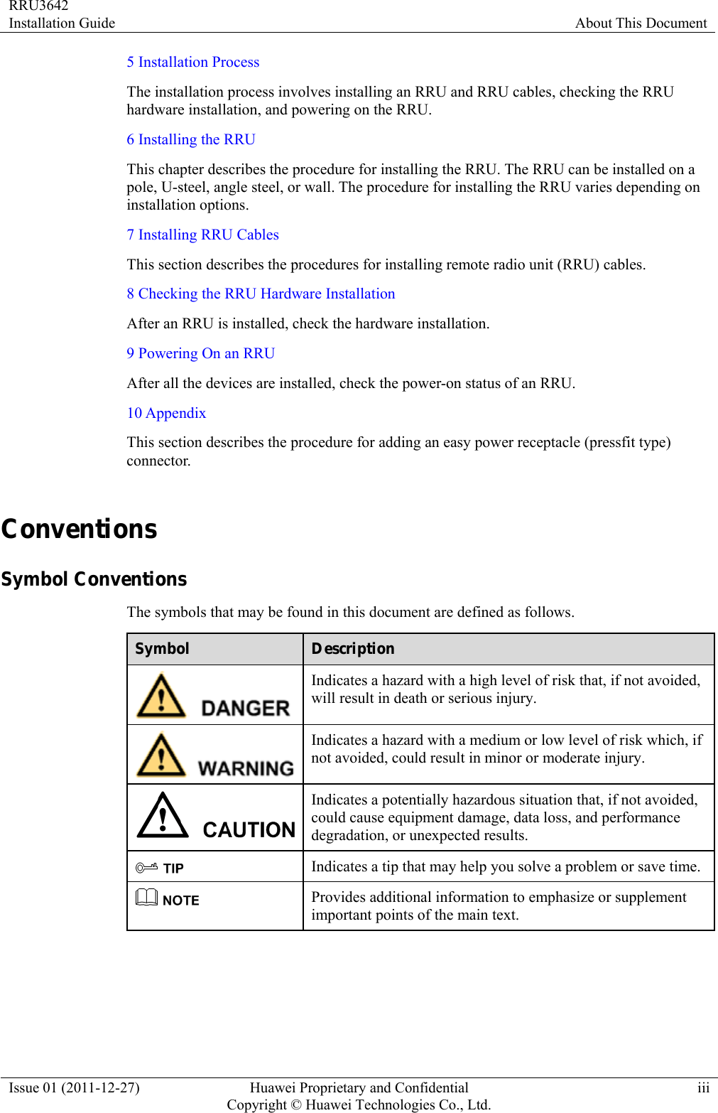
![RRU3642 Installation Guide About This Document Issue 01 (2011-12-27) Huawei Proprietary and Confidential Copyright © Huawei Technologies Co., Ltd.iv General Conventions Convention Description Times New Roman Normal paragraphs are in Times New Roman. Boldface Names of files, directories, folders, and users are in boldface. For example, log in as user root. Italic Book titles are in italics. Courier New Terminal display is in Courier New. Command Conventions Convention Description Boldface The keywords of a command line are in boldface. Italic Command arguments are in italics. [ ] Items (keywords or arguments) in square brackets [ ] are optional. { x | y | ... } Alternative items are grouped in braces and separated by vertical bars. One is selected. [ x | y | ... ] Optional alternative items are grouped in square brackets and separated by vertical bars. One or none is selected. { x | y | ... } * Alternative items are grouped in braces and separated by vertical bars. A minimum of one or a maximum of all can be selected. GUI Conventions Convention Description Boldface Buttons, menus, parameters, tabs, windows, and dialog titles are in boldface. For example, click OK. > Multi-level menus are in boldface and separated by the ">" signs. For example, choose File > Create > Folder. Keyboard Operation Format Description Key Press the key. For example, press Enter and press Tab.](https://usermanual.wiki/Huawei-Technologies/RRU3642/User-Guide-1617340-Page-5.png)
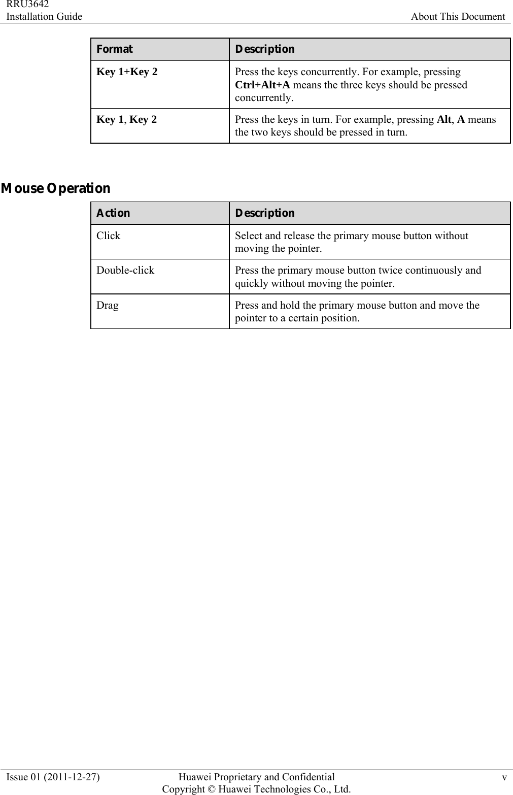

![RRU3642 Installation Guide 2 Installation Preparations Issue 01 (2011-12-27) Huawei Proprietary and Confidential Copyright © Huawei Technologies Co., Ltd.3 Heat gun Phillips screwdriver (M3 to M6) Flat-head screwdriver (M3 to M6) Rubber mallet COAX crimping tool Wire stripper Utility knife Cable cutter Adjustable wrench (capacity ≥ 32 mm [1.26 in.]) Level Torque screwdriver 5 mm (M3 to M6) (M3 to M6) Torque wrench Capacity: 17 mm [0.67 in.], 21 mm [0.82 in.], and 32 mm [1.26 in.] Combination wrench Capacity: 17 mm [0.67 in.], 21 mm [0.82 in.], and 32 mm [1.26 in.] Multimeter Marker (diameter ≤ 10 mm [0.39 in.]) Measuring tape 2.3 Skills and Requirements for Onsite Personnel Onsite personnel must be qualified and trained. Before performing any operation, onsite personnel must be familiar with correct operation methods and safety precautions. Before the installation, pay attention to the following items:](https://usermanual.wiki/Huawei-Technologies/RRU3642/User-Guide-1617340-Page-11.png)
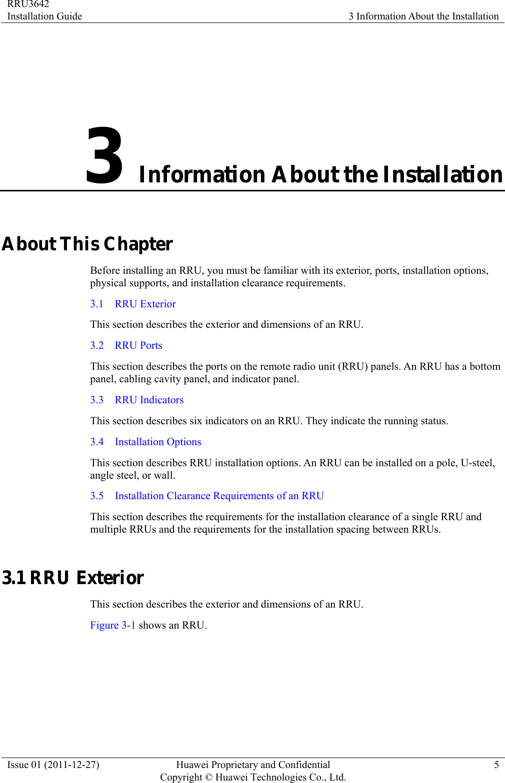
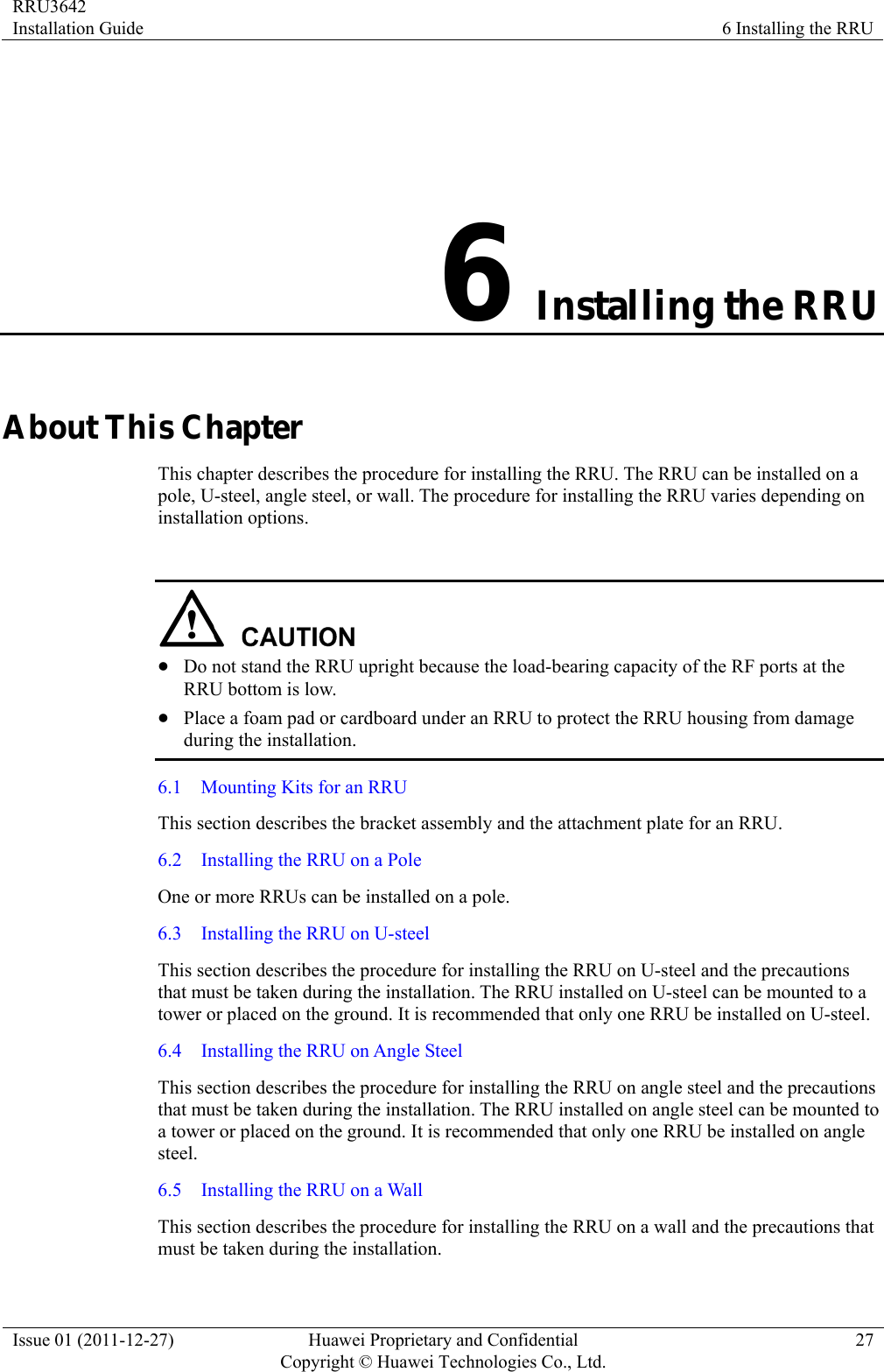
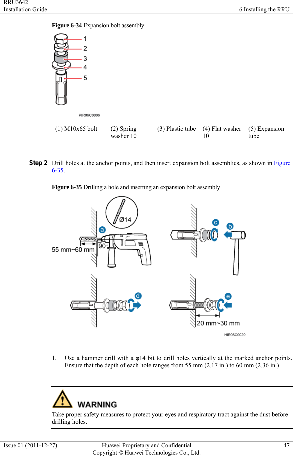
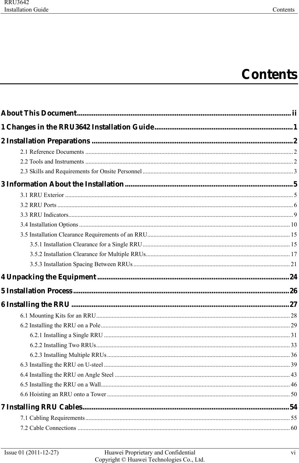
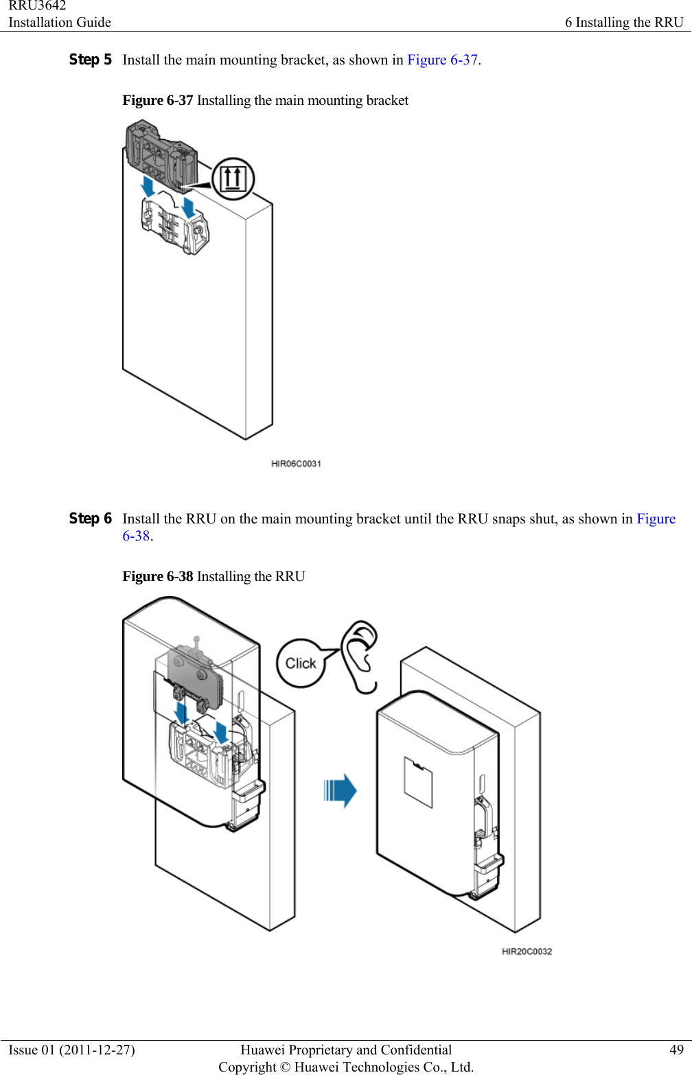
![RRU3642 Installation Guide 6 Installing the RRU Issue 01 (2011-12-27) Huawei Proprietary and Confidential Copyright © Huawei Technologies Co., Ltd.48 2. Hit the expansion bolt with a rubber mallet until the expansion tube completely enters the hole. 3. Tighten an expansion bolt slightly and place it vertically into each hole. 4. Remove the M10x65 bolt, spring washer, plastic tube, and flat washer from each expansion bolt assembly in sequence. After completely removing an expansion bolt, store the plastic tube properly. 5. Hammer the bolt into the wall. Do not hammer the expansion bolt entirely into the wall. Instead, leave 20 mm (0.79 in.) to 30 mm (1.18 in.) of the expansion bolt outside the wall. Step 3 Fit the auxiliary mounting bracket on the expansion bolt, and then use a torque wrench (17 mm [0.67 in.]) to tighten the expansion bolt to 30 N·m (265.52 lbf·in.), as shown in Figure 6-36. Figure 6-36 Fitting the auxiliary mounting bracket on expansion bolts Verify that the arrow on the auxiliary mounting bracket is pointing up. Step 4 Loosen the screws on the main mounting bracket and store them properly.](https://usermanual.wiki/Huawei-Technologies/RRU3642/User-Guide-1617340-Page-56.png)
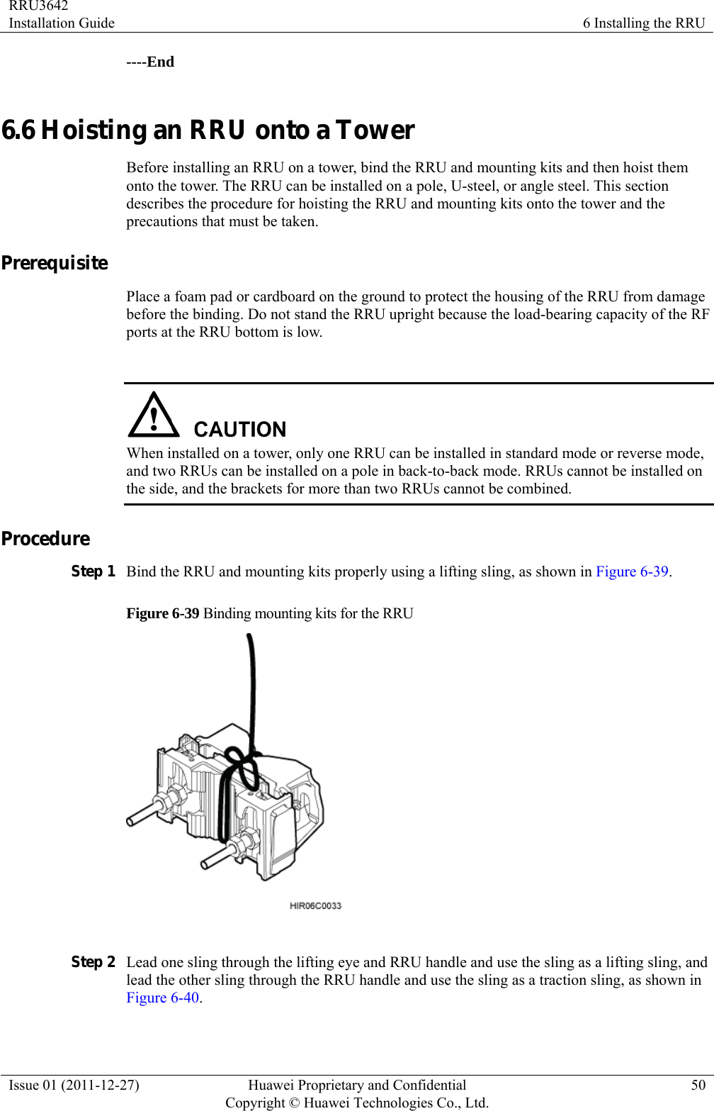

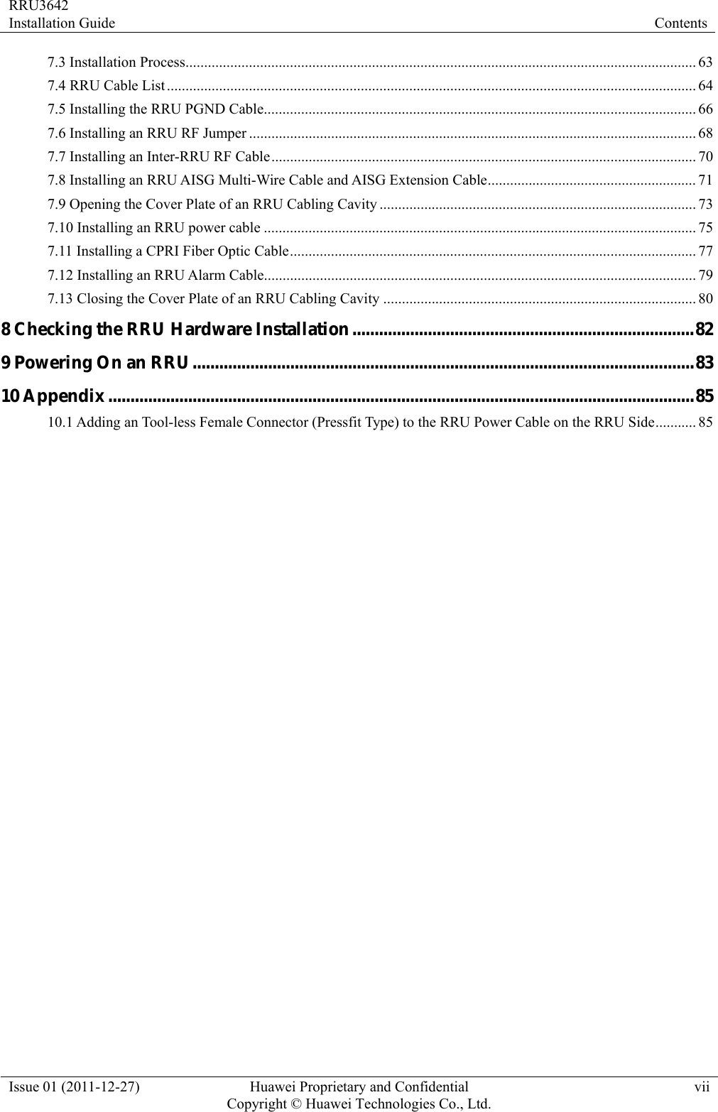
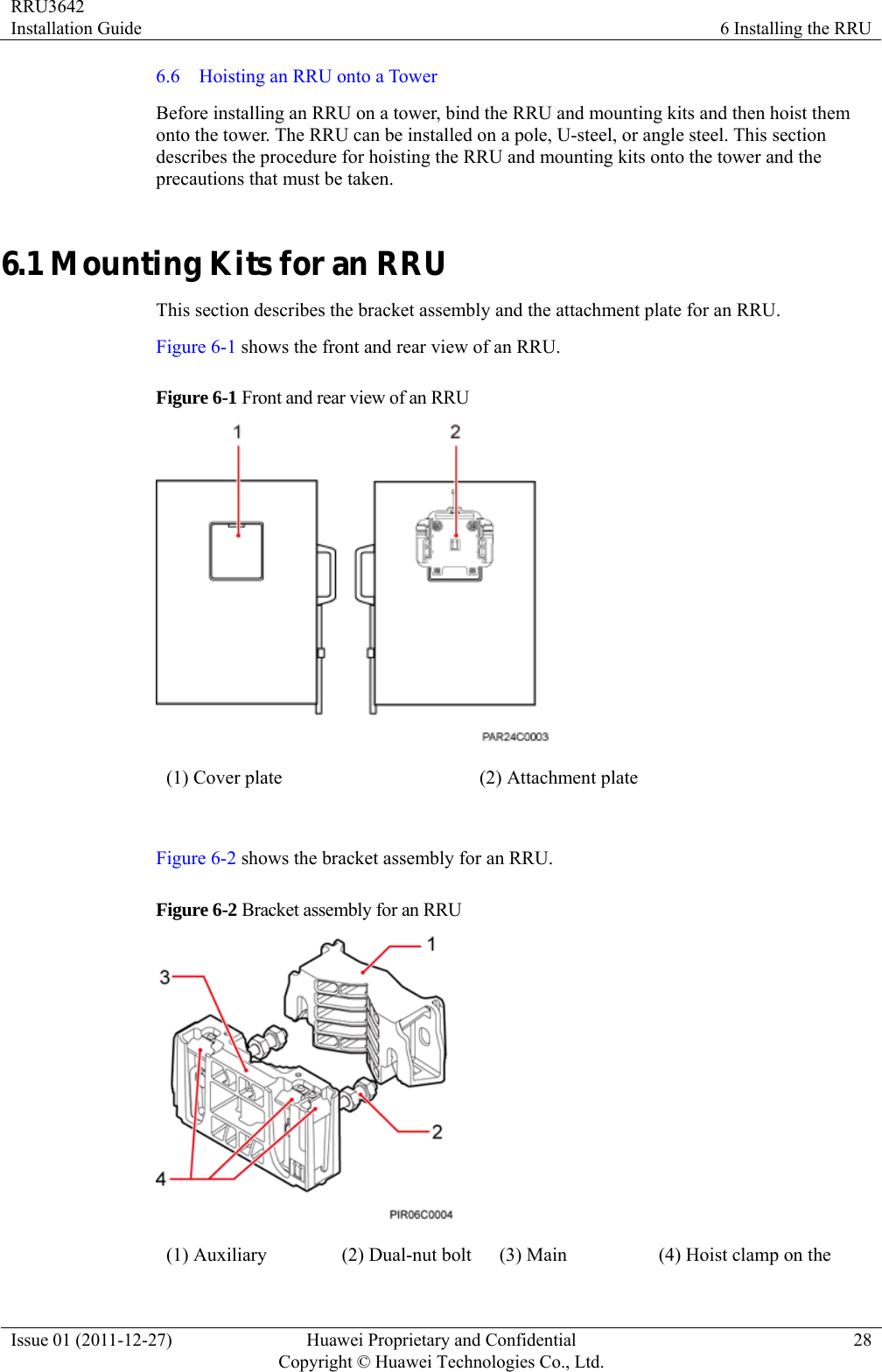
![RRU3642 Installation Guide 6 Installing the RRU Issue 01 (2011-12-27) Huawei Proprietary and Confidential Copyright © Huawei Technologies Co., Ltd.52 z Each sling has a maximum load-bearing capacity of 200 kg (441 lb), the diameter of the sling must be less than 25 mm (0.98 in.), and the angle at the top of the traction sling [by the knot] must not be greater than 60 degrees. z When hoisting the RRU and mounting kits onto the tower, protect them from colliding with the ground and tower. z Hoist the RRU onto the tower before it is installed on a pole, angle steel, or U-steel. z Do not hoist the RRU by the handle or lifting eye only, as shown in Figure 6-41 and Figure 6-42. Figure 6-41 Incorrect binding method Figure 6-42 Incorrect binding method](https://usermanual.wiki/Huawei-Technologies/RRU3642/User-Guide-1617340-Page-60.png)
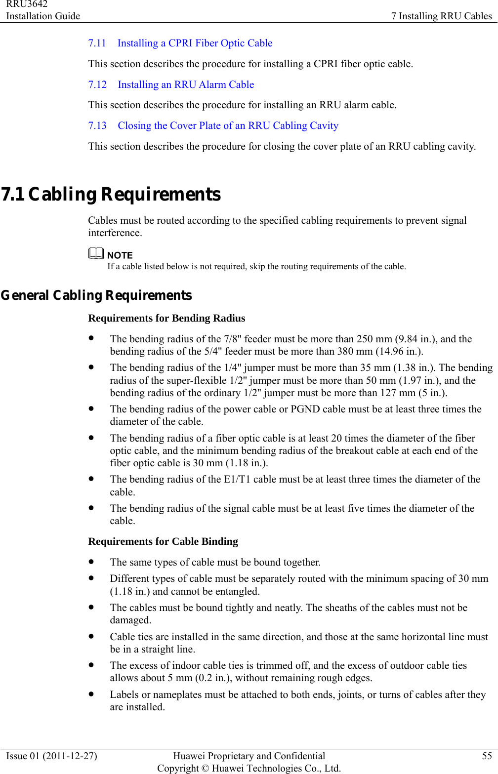
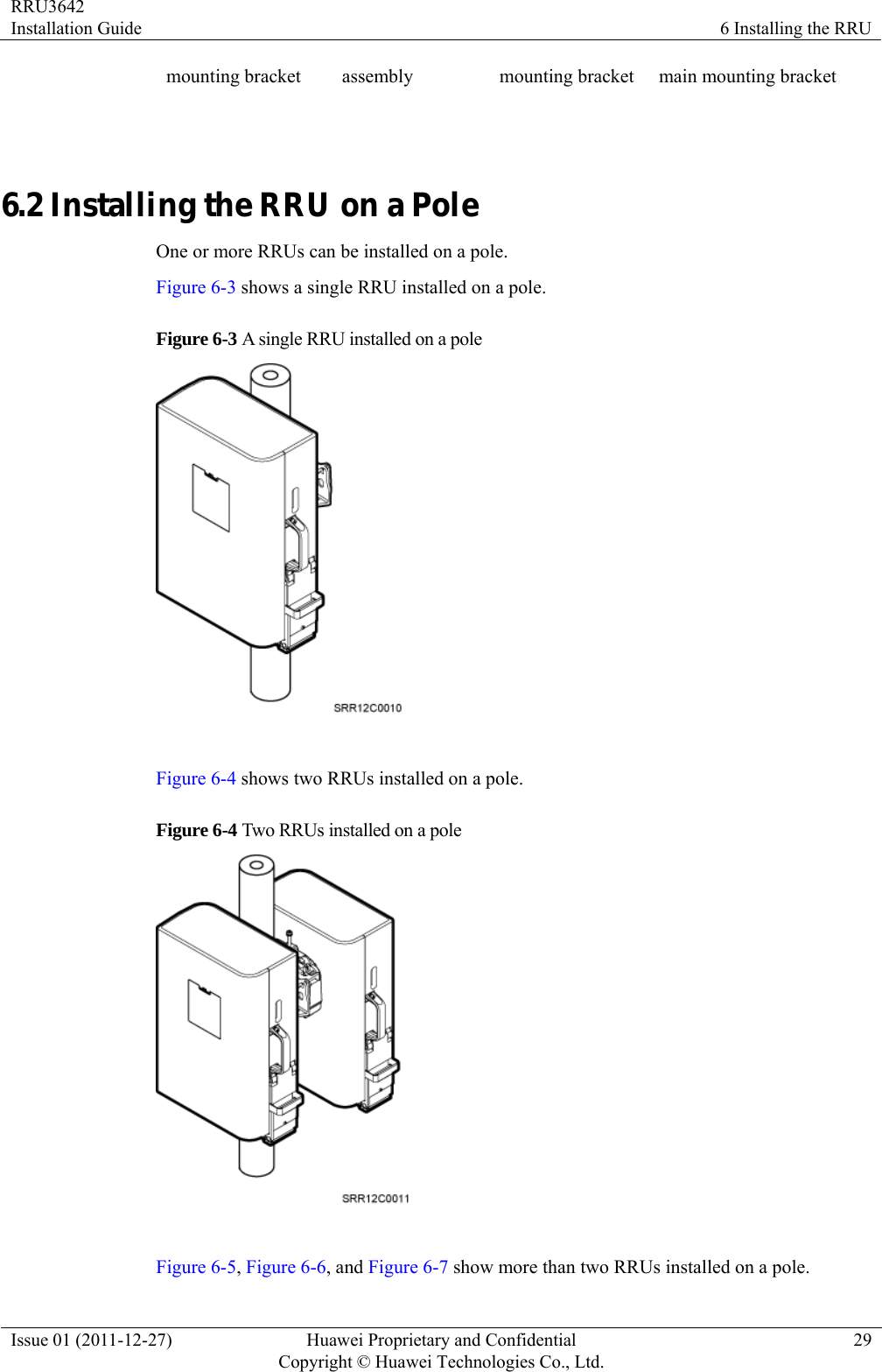
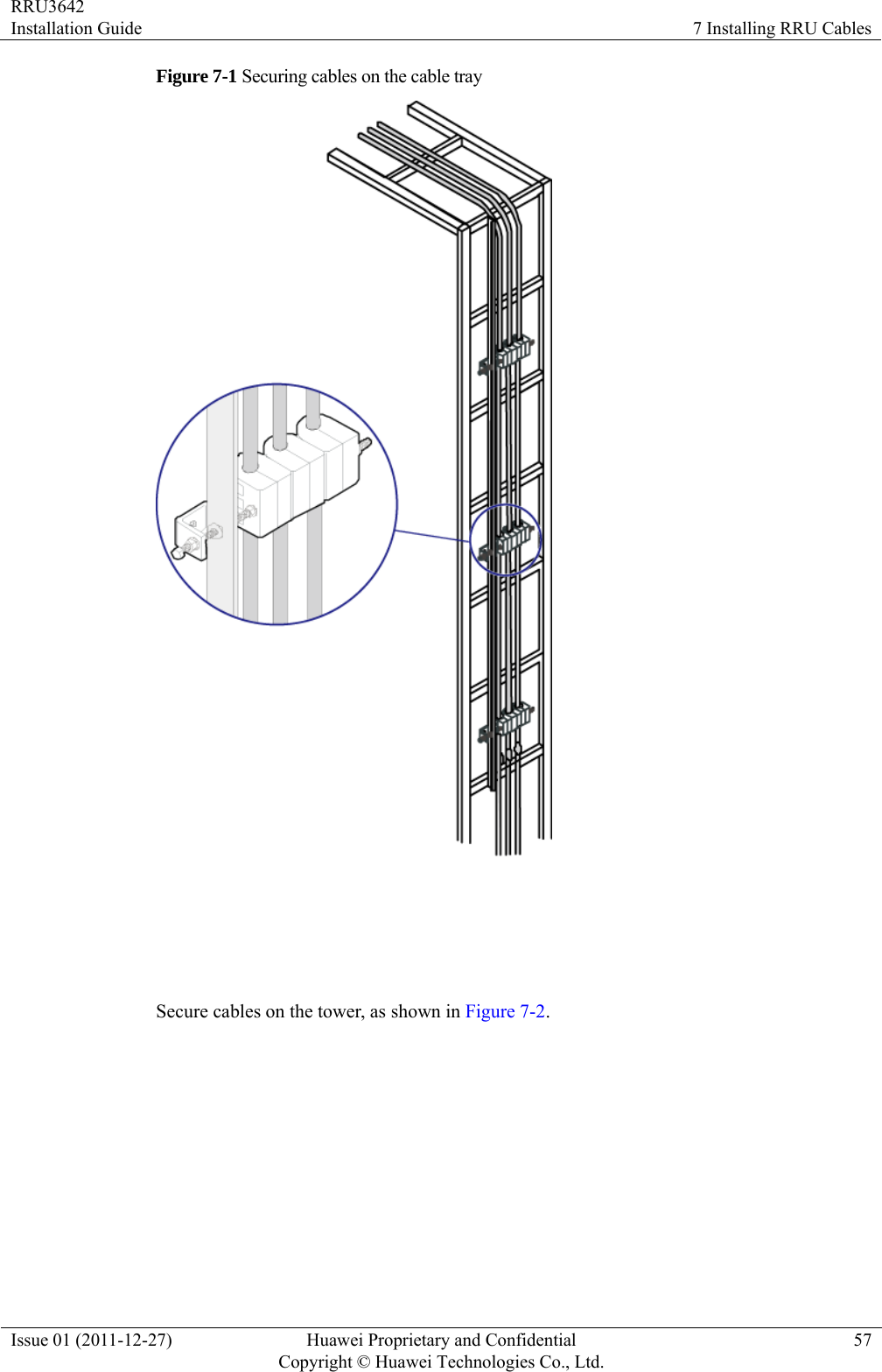
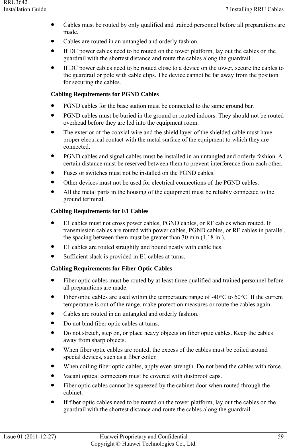
![RRU3642 Installation Guide 7 Installing RRU Cables Issue 01 (2011-12-27) Huawei Proprietary and Confidential Copyright © Huawei Technologies Co., Ltd.56 Security Requirements z Cables should be placed away from sharp objects or wall burrs. If these positions are inevitable, protect the cables with protection pipes. z Cables must be routed away from heat sources, or heat-insulation materials are added between cables and heat sources. z Sufficient slack (recommended for about 0.1 m [0.33 ft.]) is provided in cables at turns or the position close to a device, facilitating cable and device maintenance. Indoor Cabling Requirements z Cables are routed indoors through the feeder window. z Drip loops must be made outside the feeder window, and the requirements for the minimum bending radius are met. z When cables are routed indoors, engineers are required indoors for cooperation. z The feeder window must be waterproofed. Outdoor Cabling Requirements z Cables routed outdoors must be led through a pipe when they may be damaged. z AC power cables, transmission cables, and cables buried in the ground must be protected. z If cables at the cabinet bottom need to be routed through a pipe along the ground, lead the pipe into the cabinet base for about 3 m (9.84 ft.) to 5 m (16.4 ft.), not into the cabinet. Block the pipe with waterproof tape or silicon gel, and secure the pipe to the cable hole at the cabinet bottom with metal piece. z If cables at the cabinet bottom need to be routed through a pipe along the metal cable trough, do not lead the pipe into the cabinet base. The cable trough must be sealed and routed through the cable hole at the cabinet bottom. z Cables are secured with cable clips. z Cables are routed neatly along the specified cabling direction and secured with cable clips. z The positions for cable clips are determined onsite. For example, the cable clips for the 7/8" feeder are installed at the spacing of 1.5 m (4.92 ft.) to 2 m (6.56 ft.) in the same direction, and the cable clips for the power cables are installed at the spacing of 1 m (3.28 ft.) to 1.5 m (4.92 ft.) in the same direction. z Cable clips must be vertical with cables, and the cables in a cable clip must be parallel. z After routing cables neatly and correctly, tighten the screws on cable clips. Secure cables on the cable tray, as shown in Figure 7-1.](https://usermanual.wiki/Huawei-Technologies/RRU3642/User-Guide-1617340-Page-64.png)
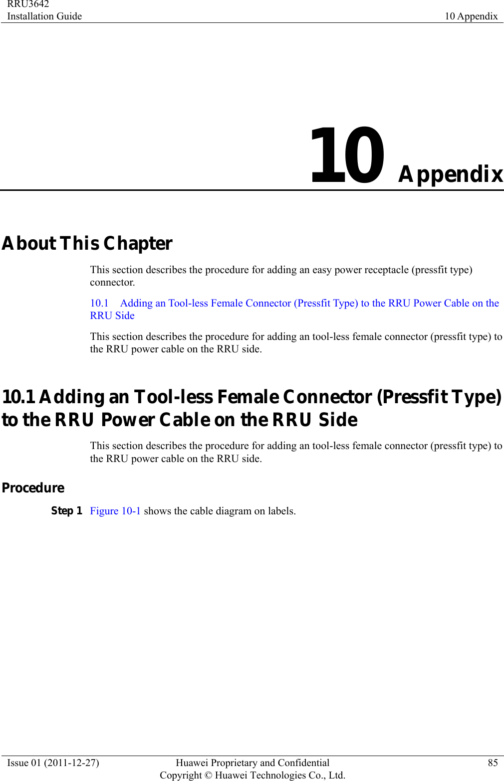
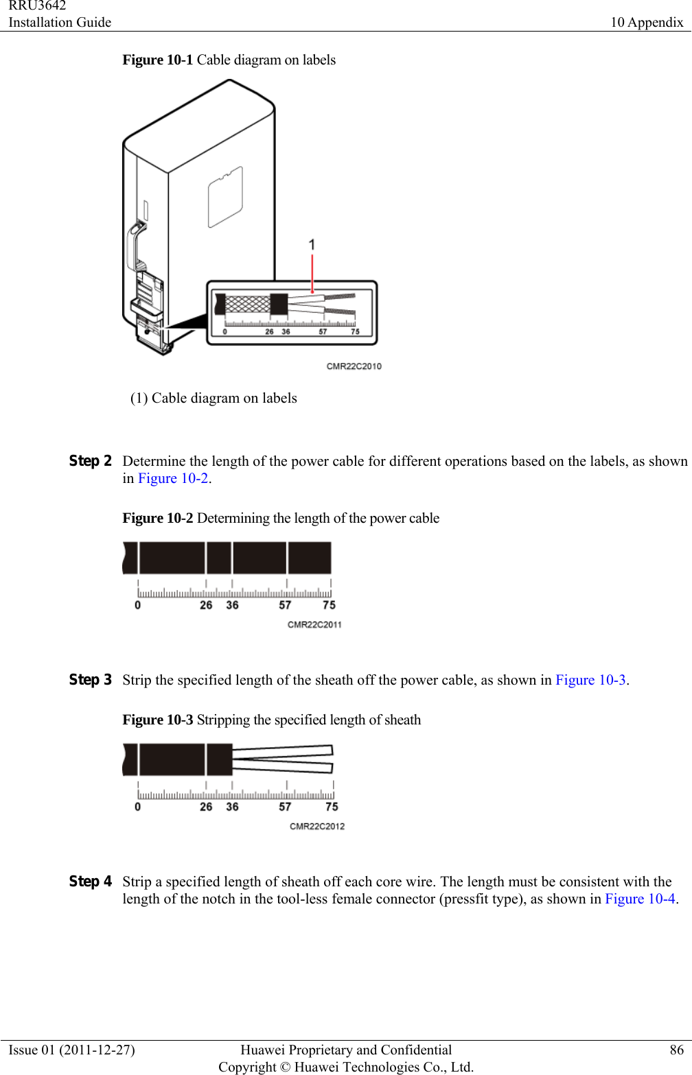
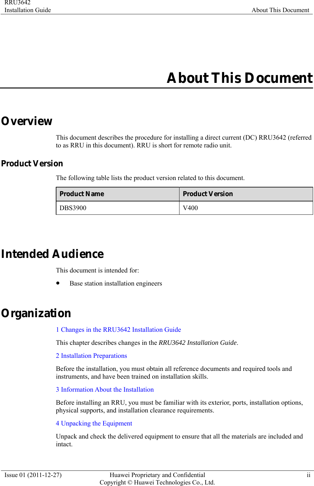
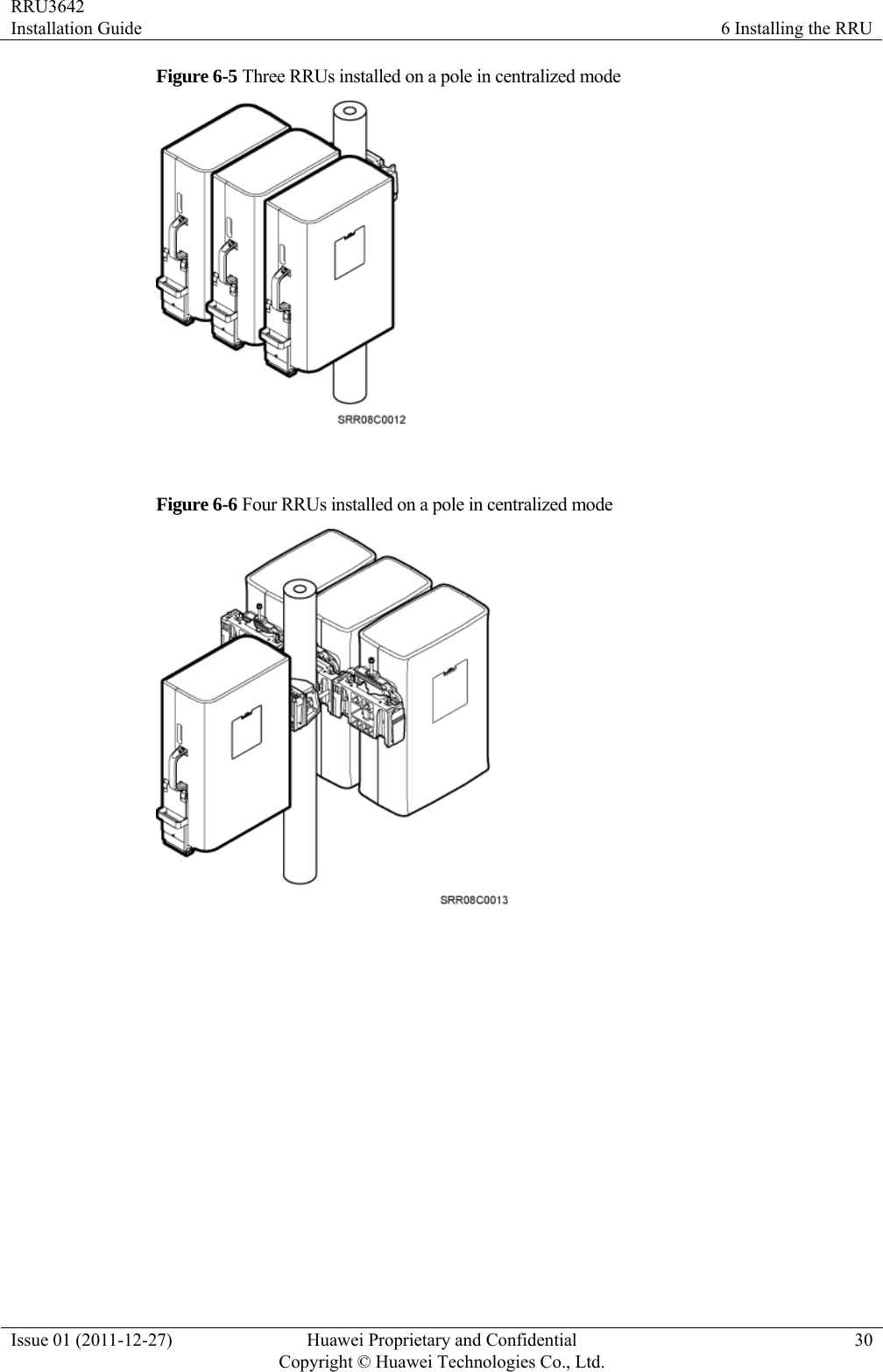
![RRU3642 Installation Guide 10 Appendix Issue 01 (2011-12-27) Huawei Proprietary and Confidential Copyright © Huawei Technologies Co., Ltd.88 Figure 10-7 Adding an tool-less female connector (pressfit type) to two core wires Step 6 Strip the specified length of the sheath off the power cable to expose the intact shield layer, as shown in Figure 10-8. Figure 10-8 Stripping the sheath off the power cable Each core wire is exposed outside the tool-less female connector (pressfit type) for 1.5 mm (0.059 [in.]), as shown in Figure 10-9.](https://usermanual.wiki/Huawei-Technologies/RRU3642/User-Guide-1617340-Page-96.png)