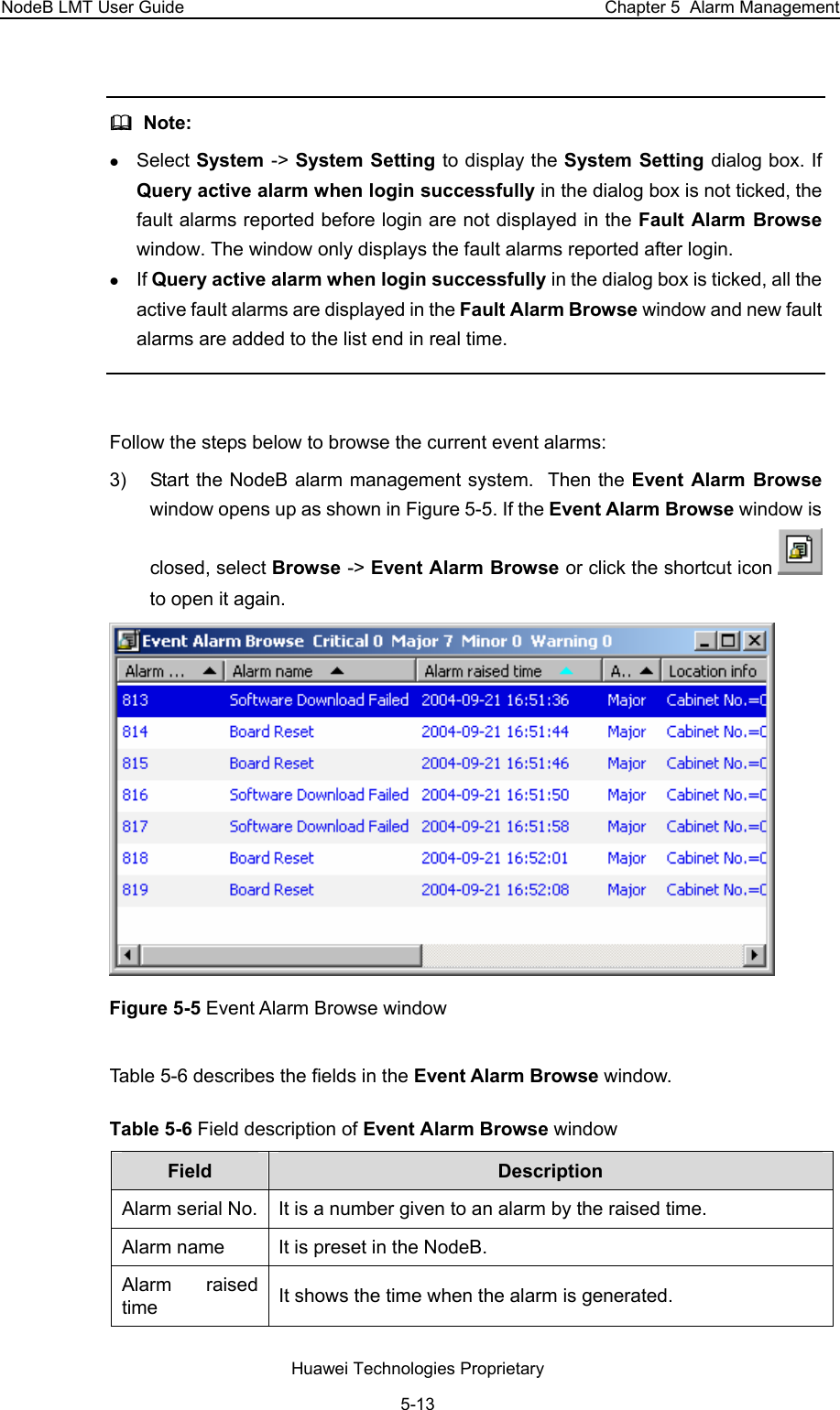
Huawei Technologies RRU3801C-19202 WCDMA Base Station User Manual 00 1 Cover

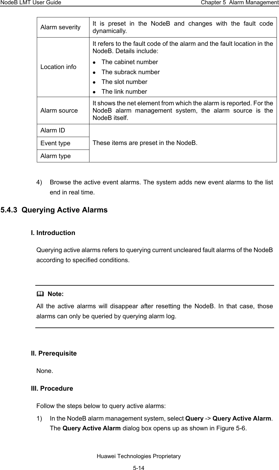
Huawei Technologies Co.,Ltd WCDMA Base Station 00 1 Cover

Contents

User Manual Part 1

  HUAWEI                NodeB LMT User Guide V100R006   Huawei Technologies Proprietary
 NodeB LMT User Guide  Volume  NodeB LMT User Guide Manual Version  T2-031640-20051230-C-1.60 Product Version  V100R006 BOM  31161640  Huawei Technologies Co., Ltd. provides customers with comprehensive technical support and service. Please feel free to contact our local office or company headquarters.  Huawei Technologies Co., Ltd. Address: Administration Building, Huawei Technologies Co., Ltd.,                  Bantian, Longgang District, Shenzhen, P. R. China Postal Code: 518129 Website: http://www.huawei.comEmail: support@huawei.com  Huawei Technologies Proprietary
  Copyright © 2005 Huawei Technologies Co., Ltd.  All Rights Reserved No part of this manual may be reproduced or transmitted in any form or by any means without prior written consent of Huawei Technologies Co., Ltd. Trademarks , HUAWEI, C&C08, EAST8000, HONET,  , ViewPoint, INtess, ETS, DMC, TELLIN, InfoLink, Netkey, Quidway, SYNLOCK, Radium,  M900/M1800, TELESIGHT, Quidview, Musa, Airbridge, Tellwin, Inmedia, VRP, DOPRA, iTELLIN, HUAWEI OptiX, C&C08 iNET, NETENGINE, OptiX, iSite, U-SYS, iMUSE, OpenEye, Lansway, SmartAX, infoX, TopEng are trademarks of Huawei Technologies Co., Ltd. All other trademarks mentioned in this manual are the property of their respective holders.  Notice The information in this manual is subject to change without notice. Every effort has been made in the preparation of this manual to ensure accuracy of the contents, but all statements, information, and recommendations in this manual do not constitute the warranty of any kind, express or implied.  Huawei Technologies Proprietary
 Summary of Updates This section provides the update history of this manual and introduces the contents of subsequent updates. Update History This manual is updated for a major product version to maintain consistency with system hardware or software versions and to incorporate customer suggestions. Manual Version  Notes T2-031640-20051230-C-1.60  Initial field trial release  Huawei Technologies Proprietary
 About This Manual Release Notes The product version that corresponds to the manual is WCDMA NodeB V100R006. Organization The manual describes routine maintenance of WCDMA NodeB. There are fourteen chapters and one appendix in the manual. Chapter 1 About This Manual describes general information about this manual.  Chapter 2 Overview describes the local maintenance terminal (LMT) system and its elements. Chapter 3 Installing LMT Application describes the installation of LMT software.  Chapter 4 Getting Started with LMT describes how to log into the NodeB through the LMT.  Chapter 5 Alarm Management describes how to manage the alarms on the NodeB though the LMT.  Chapter 6 Managing Files describes how to upload and browse files.  Chapter 7 Managing NodeB and Boards describes operations on the NodeB and the boards on the NodeB O&M system.  Chapter 8 Tracing NodeB Iub Interface Signaling describes how to create tracing tasks and how to browse traced messages.  Chapter 9 Monitoring NodeB Performance and State in Real Time describes how to monitor the NodeB performance and state in real time.  Chapter 10 Monitoring External Environment of NodeB describes how to monitor the NodeB external environment. Chapter 11 141 Test describes the NodeB RF performance tests. Chapter 12 Managing NodeB Clock describes routine maintenance of the clock management system.  Huawei Technologies Proprietary
 Chapter 13 Managing NodeB Cells describes operations of the NodeB cell management system.  Chapter 14 NodeB Software Update and Data Configuration File Transfer describes the NodeB software upgrade and data configuration file transfer. Appendix A Acronyms and Abbreviations lists all acronyms and abbreviations in this manual with their full names. Intended Audience The manual is intended for the following readers:  z Maintenance engineers and technicians Conventions This document uses the following conventions:  I. General conventions Convention  Description Arial  Normal paragraphs are in Arial. Arial Narrow Warnings, cautions, notes and tips are in Arial Narrow.  II. Symbols Eye-catching symbols are also used in this document to highlight the points worthy of special attention during the operation. They are defined as follows:    Caution, Warning,  Danger: Means reader be extremely careful during the operation.   Note, Comment, Tip, Knowhow, Thought: Means a complementary description. Huawei Technologies Proprietary
NodeB LMT User Guide  Table of Contents Table of Contents Chapter 1 About This Manual....................................................................................................... 1-1 1.1 Purpose of This Manual..................................................................................................... 1-1 1.2 Intended Audience............................................................................................................. 1-1 1.3 Architecture of This Manual ............................................................................................... 1-1 Chapter 2 Overview ....................................................................................................................... 2-1 2.1 About This Chapter............................................................................................................ 2-1 2.2 Introduction to LMT............................................................................................................ 2-1 2.2.1 Functions of LMT..................................................................................................... 2-1 2.2.2 LMT Configuration Requirements ........................................................................... 2-1 2.3 LMT System Composition.................................................................................................. 2-2 2.3.1 Overview ................................................................................................................. 2-2 2.3.2 NodeB O&M System ............................................................................................... 2-3 2.3.3 NodeB Alarm Management System........................................................................ 2-6 2.3.4 TraceViewer ............................................................................................................ 2-8 Chapter 3 Installing LMT Application.......................................................................................... 3-1 3.1 About This Chapter............................................................................................................ 3-1 3.2 Installation Introduction...................................................................................................... 3-1 3.2.1 Preparing for Installation ......................................................................................... 3-1 3.2.2 Impact on System.................................................................................................... 3-1 3.3 Installing LMT Software .....................................................................................................3-1 3.4 Verifying Installation......................................................................................................... 3-14 Chapter 4 Getting Started with LMT ............................................................................................ 4-1 4.1 About This Chapter............................................................................................................ 4-1 4.2 Starting LMT ...................................................................................................................... 4-1 4.2.1 Overview ................................................................................................................. 4-1 4.2.2 Setting IP Address for LMT Computer .................................................................... 4-1 4.2.3 Connecting LMT Computer to NodeB..................................................................... 4-3 4.2.4 Logging into NodeB Through LMT.......................................................................... 4-4 4.2.5 Logging into NodeB Through M2000 Server .......................................................... 4-6 4.3 Configuring LMT ................................................................................................................ 4-6 4.3.1 Configuring LMT Attributes ..................................................................................... 4-6 4.3.2 Changing Login Password ...................................................................................... 4-7 4.4 Managing Office................................................................................................................. 4-8 4.5 Locking LMT ...................................................................................................................... 4-9 4.6 Executing MML Commands............................................................................................. 4-11 4.6.1 Introduction to MML Commands ........................................................................... 4-11 4.6.2 Executing a Single MML Command...................................................................... 4-13 Huawei Technologies Proprietary i
NodeB LMT User Guide  Table of Contents 4.6.3 Executing Batch MML Commands........................................................................ 4-14 4.7 Exiting LMT ...................................................................................................................... 4-18 Chapter 5 Alarm Management......................................................................................................5-1 5.1 About This Chapter............................................................................................................ 5-1 5.2 Overview ............................................................................................................................ 5-1 5.2.1 Alarm Types ............................................................................................................ 5-1 5.2.2 Alarm Log ................................................................................................................ 5-2 5.2.3 Alarm Severity......................................................................................................... 5-2 5.2.4 Alarms Classified by Network Management ........................................................... 5-2 5.3 Configuring Alarm System Attributes................................................................................. 5-3 5.3.1 Overview ................................................................................................................. 5-3 5.3.2 Configuring Attributes of Alarm Query Window ...................................................... 5-3 5.3.3 Setting Fault Alarm Blinking Prompt ....................................................................... 5-5 5.3.4 Setting Sound Duration for Fault Alarms ................................................................ 5-5 5.3.5 Setting Dial Notify for Fault Alarms ......................................................................... 5-7 5.3.6 Setting SMS Notify for Fault Alarms........................................................................ 5-9 5.3.7 Sorting Alarms....................................................................................................... 5-10 5.4 Monitoring NodeB Alarms................................................................................................ 5-10 5.4.1 Overview ............................................................................................................... 5-10 5.4.2 Browsing Alarms ................................................................................................... 5-11 5.4.3 Querying Active Alarms......................................................................................... 5-14 5.4.4 Querying Alarm Log .............................................................................................. 5-15 5.4.5 Querying Alarm Details ......................................................................................... 5-19 5.4.6 Realtime Printing Alarms....................................................................................... 5-20 5.5 Handling NodeB Alarms .................................................................................................. 5-22 5.5.1 Overview ............................................................................................................... 5-22 5.5.2 Querying Alarm Handling Suggestions ................................................................. 5-22 5.5.3 Shielded Alarms .................................................................................................... 5-22 Chapter 6 Managing Files............................................................................................................. 6-1 6.1 About This Chapter............................................................................................................ 6-1 6.2 Overview of File Management ........................................................................................... 6-1 6.2.1 File Types................................................................................................................6-1 6.2.2 Browsing Files ......................................................................................................... 6-2 6.3 Uploading Files .................................................................................................................. 6-2 6.3.1 Uploading Operation Log ........................................................................................ 6-2 6.3.2 Uploading Equipment Archives ............................................................................... 6-5 6.3.3 Uploading Main Board Log Files ............................................................................. 6-6 6.3.4 Uploading Board Log Files...................................................................................... 6-7 6.3.5 Uploading RTWP Routine Test Log........................................................................ 6-8 6.4 Browsing Files.................................................................................................................... 6-8 6.4.1 Browsing Files on FTP Server ................................................................................ 6-8 6.4.2 Browsing Operation Log on M2000 Server............................................................. 6-9 Huawei Technologies Proprietary ii
NodeB LMT User Guide  Table of Contents Chapter 7 Managing NodeB and Boards..................................................................................... 7-1 7.1 About This Chapter............................................................................................................ 7-1 7.2 Basic Equipment Panel Operation..................................................................................... 7-1 7.2.1 Introduction to Equipment Panel............................................................................. 7-1 7.2.2 Functions of Equipment Panel ................................................................................ 7-1 7.2.3 Interface of Equipment Panel.................................................................................. 7-1 7.2.4 Starting Equipment Panel ....................................................................................... 7-3 7.2.5 Showing or Hiding Board Indicators........................................................................ 7-4 7.2.6 Showing or Hiding Fault Bar ................................................................................... 7-4 7.3 NodeB-level Operation ...................................................................................................... 7-5 7.3.1 Overview ................................................................................................................. 7-5 7.3.2 Querying NodeB Running Version .......................................................................... 7-5 7.3.3 Querying NodeB Software Version ......................................................................... 7-6 7.3.4 Modifying NodeB Time............................................................................................ 7-7 7.3.5 Modifying NodeB Password .................................................................................... 7-8 7.3.6 Resetting NodeB ..................................................................................................... 7-9 7.4 Board-level Operation...................................................................................................... 7-10 7.4.1 Overview ............................................................................................................... 7-10 7.4.2 Querying Board Status.......................................................................................... 7-11 7.4.3 Querying Active Alarms on Board ......................................................................... 7-13 7.4.4 Querying Board Version........................................................................................ 7-13 7.4.5 Querying E1/T1 Status.......................................................................................... 7-14 7.4.6 Querying E1/T1 Work Mode.................................................................................. 7-16 7.4.7 Querying STM-1 Status......................................................................................... 7-18 7.4.8 Querying STM-1 Work Mode ................................................................................ 7-19 7.4.9 Blocking/Unblocking Board ................................................................................... 7-20 7.4.10 Resetting Board................................................................................................... 7-21 7.4.11 Adding/Removing Board ..................................................................................... 7-21 Chapter 8 Tracing NodeB Iub Interface Signaling ..................................................................... 8-1 8.1 About This Chapter............................................................................................................ 8-1 8.2 Overview ............................................................................................................................ 8-1 8.2.1 Principle of Tracing NodeB Iub Interface Signaling ................................................ 8-1 8.2.2 Introduction to NodeB Iub Interface Tracing ........................................................... 8-2 8.3 Creating NodeB Iub Interface Tracing Task ...................................................................... 8-2 8.4 Browsing NodeB Traced Message .................................................................................... 8-6 8.4.1 Browsing NodeB Traced Message Online .............................................................. 8-6 8.4.2 Setting Browsing Properties of NodeB Traced Message........................................ 8-7 8.4.3 Saving NodeB Traced Messages Automatically ..................................................... 8-8 8.4.4 Saving NodeB Traced Messages Manually ............................................................ 8-9 8.4.5 Browsing NodeB Traced Messages Offline ............................................................ 8-9 8.4.6 Filtering NodeB Traced Messages........................................................................ 8-11 Huawei Technologies Proprietary iii
NodeB LMT User Guide  Table of Contents Chapter 9 Monitoring NodeB Performance and State in Real Time......................................... 9-1 9.1 About This Chapter............................................................................................................ 9-1 9.2 Overview ............................................................................................................................ 9-1 9.3 Querying CPU/DSP Occupancy ........................................................................................ 9-1 9.4 Querying Cell Service Resource........................................................................................ 9-3 9.5 Testing NodeB RTWP ....................................................................................................... 9-5 9.6 Testing NodeB Clock .........................................................................................................9-7 9.7 Scanning NodeB Rx Frequency ........................................................................................ 9-8 9.8 Testing MTRU Output Power........................................................................................... 9-11 9.9 Testing MTRU Temperature ............................................................................................ 9-12 9.10 Testing MRRU Output Power ........................................................................................ 9-14 9.11 Testing MRRU Temperature.......................................................................................... 9-15 9.12 Querying Board Service Resource ................................................................................ 9-16 9.13 Routine Testing NodeB E1/T1 Performance ................................................................. 9-18 9.14 Routine Testing STM-1 Performance ............................................................................ 9-19 Chapter 10 Monitoring External Environment of NodeB......................................................... 10-1 10.1 About This Chapter........................................................................................................ 10-1 10.2 Monitoring External Environment of NodeB .................................................................. 10-1 10.2.1 Overview of External Environment...................................................................... 10-1 10.2.2 Monitoring Input Power Supply ........................................................................... 10-1 10.2.3 Monitoring Temperature and Humidity................................................................ 10-2 10.2.4 Smoke and Anti-theft Alarms .............................................................................. 10-3 10.2.5 Customized Alarms ............................................................................................. 10-3 10.3 Monitoring Input Power Supply...................................................................................... 10-3 10.3.1 Overview ............................................................................................................. 10-3 10.3.2 Setting NEMU Input Voltage Alarm Thresholds.................................................. 10-4 10.3.3 Querying NEMU Alarm Thresholds for Input Voltage ......................................... 10-4 10.3.4 Querying NEMU Input Voltage............................................................................ 10-4 10.4 Monitoring Temperature and Humidity .......................................................................... 10-4 10.4.1 Overview ............................................................................................................. 10-4 10.4.2 Querying NEMU Temperature and Humidity ...................................................... 10-4 10.4.3 Setting Thresholds of NEMU Temperature and Humidity................................... 10-5 10.4.4 Querying Thresholds of NEMU Temperature and Humidity ............................... 10-5 10.5 Smoke and Anti-theft Alarms......................................................................................... 10-5 10.5.1 Overview ............................................................................................................. 10-5 10.5.2 Clearing NEMU Smoke and Enclosure Alarms................................................... 10-6 Chapter 11 141 Test..................................................................................................................... 11-1 11.1 About This Chapter........................................................................................................ 11-1 11.2 Overview ........................................................................................................................ 11-1 11.2.1 Introduction to 141 Test ...................................................................................... 11-1 11.2.2 Precautions ......................................................................................................... 11-1 11.3 Setting Cell Parameters................................................................................................. 11-2 Huawei Technologies Proprietary iv
NodeB LMT User Guide  Table of Contents 11.4 UL 141 Test ................................................................................................................... 11-8 11.4.1 Introduction to UL 141 Test................................................................................. 11-8 11.4.2 Testing UL DPCH................................................................................................ 11-9 11.4.3 Testing UL RACH.............................................................................................. 11-13 11.5 DL 141 Test ................................................................................................................. 11-16 11.5.1 Introduction to DL 141 Test............................................................................... 11-16 11.5.2 Testing Max Transmit Power ............................................................................ 11-17 11.5.3 Testing CPICH Power Accuracy ....................................................................... 11-18 11.5.4 Testing Frequency Error ................................................................................... 11-19 11.5.5 Testing Transmit Intermodulation...................................................................... 11-21 11.5.6 Testing IPDL Time Mask................................................................................... 11-22 11.5.7 Testing Power Control Steps ............................................................................ 11-23 11.5.8 Testing Power Control Step or Dynamic Range ............................................... 11-26 11.5.9 Testing Total Dynamic Range........................................................................... 11-28 11.5.10 Testing Occupied Bandwidth .......................................................................... 11-29 11.5.11 Testing Spurious Emission.............................................................................. 11-30 11.5.12 Testing Spectrum Emission ............................................................................ 11-33 11.5.13 Testing ACLR.................................................................................................. 11-34 11.5.14 Testing EVM.................................................................................................... 11-35 11.5.15 Testing PCDE.................................................................................................. 11-36 Chapter 12 Managing NodeB Clock........................................................................................... 12-1 12.1 About This Chapter........................................................................................................ 12-1 12.2 Overview of NodeB Clock.............................................................................................. 12-1 12.2.1 Principle of Clock ................................................................................................ 12-1 12.2.2 Center Frequency DA Value ............................................................................... 12-1 12.2.3 Current Frequency DA Value .............................................................................. 12-1 12.2.4 Initial DA Value.................................................................................................... 12-2 12.3 Querying Clock Status ................................................................................................... 12-2 12.3.1 Overview of Querying Clock Status .................................................................... 12-2 12.3.2 Introduction to Clock Status ................................................................................ 12-2 12.3.3 Querying Current Clock Status ........................................................................... 12-3 12.3.4 Querying History Clock Record........................................................................... 12-4 12.4 Managing NodeB Clock Source..................................................................................... 12-5 12.4.1 Overview ............................................................................................................. 12-5 12.4.2 Introduction to NodeB Clock Source................................................................... 12-5 12.4.3 Setting NodeB Clock Work Mode........................................................................ 12-5 12.4.4 Setting NodeB Clock Source............................................................................... 12-6 12.4.5 Testing NodeB Clock Source Quality.................................................................. 12-6 12.5 Setting NodeB Clock Frequency.................................................................................... 12-6 12.5.1 Overview ............................................................................................................. 12-6 12.5.2 Introduction to Clock Frequency Values ............................................................. 12-7 12.5.3 Setting NodeB Clock Center Frequency ............................................................. 12-7 Huawei Technologies Proprietary v
NodeB LMT User Guide  Table of Contents 12.5.4 Setting NodeB Clock Current Frequency............................................................ 12-7 Chapter 13 Managing NodeB Cells............................................................................................ 13-1 13.1 About This Chapter........................................................................................................ 13-1 13.2 Overview ........................................................................................................................ 13-1 13.2.1 Local Cell and Logical Cell.................................................................................. 13-1 13.2.2 Cell Radius and Handover Radius...................................................................... 13-1 13.2.3 Cell Status ........................................................................................................... 13-2 13.2.4 Blocking Cell........................................................................................................ 13-2 13.3 Querying Cell Configuration........................................................................................... 13-3 13.3.1 Overview of Cell Configuration Query................................................................. 13-3 13.3.2 Introduction to Cell Configuration and Cell Status .............................................. 13-3 13.3.3 Querying Cell Configuration ................................................................................ 13-4 13.3.4 Querying Cell Status ........................................................................................... 13-4 13.3.5 Auditing Resources ............................................................................................. 13-4 13.4 Modifying Local Cell....................................................................................................... 13-5 13.4.1 Overview of Modifying Local Cell ........................................................................ 13-5 13.4.2 Introduction to Cell Parameters........................................................................... 13-5 13.4.3 Modifying Local Cell Parameters ........................................................................ 13-5 13.4.4 Blocking/Unblocking Cell..................................................................................... 13-5 Chapter 14 NodeB Software Update and Data Configuration File Transfer .......................... 14-1 14.1 About This Chapter........................................................................................................ 14-1 14.2 Overview of Software Update ........................................................................................ 14-1 14.3 Upgrading NodeB Software ........................................................................................... 14-1 14.3.1 Overview of Upgrading NodeB Software ............................................................ 14-1 14.3.2 Introduction to NodeB Software .......................................................................... 14-2 14.3.3 Procedure of Upgrading NodeB Software........................................................... 14-2 14.3.4 Downloading NodeB Software ............................................................................ 14-3 14.3.5 Supplying NodeB Software ................................................................................. 14-8 14.3.6 Activating NodeB Software ............................................................................... 14-10 14.3.7 Activating Board Software................................................................................. 14-11 14.3.8 Synchronizing Version ...................................................................................... 14-13 14.4 Upgrading NodeB BOOTROM..................................................................................... 14-14 14.4.1 Overview ........................................................................................................... 14-14 14.4.2 Introduction to BOOTROM Software ................................................................ 14-14 14.4.3 Procedure of Upgrading NodeB BOOTROM Software..................................... 14-14 14.4.4 Downloading NodeB BOOTROM Package....................................................... 14-15 14.4.5 Activating NodeB BOOTROM........................................................................... 14-18 14.4.6 Activating Board BOOTROM ............................................................................ 14-19 14.5 Upgrading Patches ...................................................................................................... 14-19 14.5.1 Overview ........................................................................................................... 14-19 14.5.2 Introduction to Patch ......................................................................................... 14-19 14.5.3 Procedure of Upgrading Patches ...................................................................... 14-19 Huawei Technologies Proprietary vi
NodeB LMT User Guide  Table of Contents 14.5.4 Downloading Patch Package ............................................................................ 14-20 14.5.5 Activating Patches............................................................................................. 14-22 14.6 Downloading Data Configuration File .......................................................................... 14-23 14.6.1 Introduction Data Configuration File ................................................................. 14-23 14.6.2 Downloading Data Configuration File ............................................................... 14-23 14.6.3 Backing up Data Configuration File .................................................................. 14-25 Appendix A Acronyms and Abbreviations .................................................................................A-1                Huawei Technologies Proprietary vii
NodeB LMT User Guide   Table of Contents Table of Contents Chapter 1 About This Manual....................................................................................................... 1-1 1.1 Purpose of This Manual..................................................................................................... 1-1 1.2 Intended Audience............................................................................................................. 1-1 1.3 Architecture of This Manual ............................................................................................... 1-1 Huawei Technologies Proprietary i
NodeB LMT User Guide   Chapter 1  About This Manual Chapter 1  About This Manual  1.1  Purpose of This Manual This manual describes z Installation of the NodeB local maintenance terminal (LMT) z Functions and interfaces of each element in LMT  z Operation guide to NodeB routine operation and maintenance The NodeB routine maintenance is mainly conducted through the iManager M2000 server. For O&M guide to the M2000 server, see iManager M2000 Mobile Element Management System Operation Manual. 1.2  Intended Audience This manual is intended for those who operate and maintain the NodeB on the LMT system. They must have basic operation skills of MS Windows operating system and understandings of the NodeB.  1.3  Architecture of This Manual  There are 14 chapters and an appendix in this manual.  z Chapter 1: describes general information about this manual.  z Chapter 2: describes the local maintenance terminal (LMT) system and its elements. z Chapter 3: describes the installation of LMT software.  z Chapter 4: describes how to log into the NodeB through the LMT.  z Chapter 5: describes how to manage the alarms on the NodeB though the LMT.  z Chapter 6: describes how to upload and browse files.  z Chapter 7: describes operations on the NodeB and the boards on the NodeB O&M system.  z Chapter 8: describes how to create tracing tasks and how to browse traced messages.  z Chapter 9: describes how to monitor the NodeB performance and state in real time.  z Chapter 10: describes how to monitor the NodeB external environment. z Chapter 11: describes the NodeB RF performance tests. z Chapter 12: describes routine maintenance of the clock management system.  z Chapter 13: describes operations of the NodeB cell management system.  Huawei Technologies Proprietary 1-1
NodeB LMT User Guide   Chapter 1  About This Manual z Chapter 14: describes the NodeB software upgrade and data configuration file transfer.  Huawei Technologies Proprietary 1-2
NodeB LMT User Guide  Table of Contents Table of Contents Chapter 2 Overview....................................................................................................................... 2-1 2.1 About This Chapter............................................................................................................ 2-1 2.2 Introduction to LMT............................................................................................................ 2-1 2.2.1 Functions of LMT..................................................................................................... 2-1 2.2.2 LMT Configuration Requirements ........................................................................... 2-1 2.3 LMT System Composition.................................................................................................. 2-2 2.3.1 Overview ................................................................................................................. 2-2 2.3.2 NodeB O&M System ............................................................................................... 2-3 2.3.3 NodeB Alarm Management System........................................................................ 2-6 2.3.4 TraceViewer ............................................................................................................ 2-9 Huawei Technologies Proprietary i
NodeB LMT User Guide  Chapter 2  Overview Chapter 2  Overview 2.1  About This Chapter This chapter describes the local maintenance terminal (LMT) system and its elements, including: z Functions z Configuration requirements z Compositions z Main interfaces 2.2  Introduction to LMT 2.2.1  Functions of LMT The LMT of the NodeB series provides graphic user interface (GUI) for z NodeB test z Local maintenance z Troubleshooting 2.2.2  LMT Configuration Requirements  The computer used to install the LMT software must meet the following requirements: z Software  z Hardware z Communications I. Hardware Configuration Requirements  Table 2-1 shows the hardware configuration requirements to be met for the computer used to install the LMT software.  Table 2-1  Hardware configuration list Item  Quantity Recommended configuration Minimum configuration CPU  1  2.4 G  400 M RAM  1  512 M  64 M Huawei Technologies Proprietary 2-1
NodeB LMT User Guide  Chapter 2  Overview Recommended  Minimum Item  Quantity configuration  configuration Hard disk  1  40 G  1 G (the minimum available space) Display adapter resolution  --  1024 x 768  800 x 600 CD drive  1  --  -- Network adapter  1  10&100 M  10&100 M Others  1 x 3  Modem, sound card and sound box  --  II. Software Configuration Requirements  Table 2-2 shows the software configuration requirements to be met for the computer used to install the LMT software.  Table 2-2  Software configuration list Item  Standard configuration Operating system  Windows 2000 Professional (SP4) or above of English Default language of operating system  Western Europe and United States Web browser  Microsoft Internet Explorer 5.5 or above    Note:  It is recommended that the LMT software be installed in a standard operating system. Otherwise, they might not be compatible.  III. Communications Requirements  The computer supports the TCP/IP protocol.  2.3  LMT System Composition  2.3.1  Overview  The LMT communicates with the NodeB through LAN or WAN. You can maintain a NodeB through the LMT computer. Huawei Technologies Proprietary 2-2
NodeB LMT User Guide  Chapter 2  Overview The NodeB LMT consists of z NodeB O&M system z NodeB alarm management system z TraceViewer 2.3.2  NodeB O&M System I. Functions The O&M system provides MML client and GUI access to maintain NodeB, including: z Operating MML client: runs a single command on the platform of the MML Client. z Tracing management: manages the tracing messages of Iub interface.  z Software management: downloads and backs up configuration files, and upgrades software. z Realtime state monitoring: including CPU/DSP occupancy, board or cell service resource query, RTWP measurement, and clock test. z Test management: supports 141 tests. z Equipment maintenance: controls board reset and block/unblock, and helps retrieve board data. z Clock maintenance: provides routine maintenance for the NodeB timing. z Cell management: retrieves and modifies NodeB cells data, and blocks or unblocks NodeB cells. II. Interface  The interface of the NodeB O&M system consists of: z System menu  z Toolbar  z Navigation tree pane  z Object pane  z Output pane  z Status bar  z MML client  Figure 2-1 shows the NodeB O&M System window. Huawei Technologies Proprietary 2-3
NodeB LMT User Guide  Chapter 2  Overview  Figure 2-1 NodeB O&M System window Table 2-3 describes the fields of the NodeB O&M System window. Table 2-3  Filed description of O&M System window No.  Field   Description 1 Menu bar The menu bar includes System, Service, View, Window and Help menus. The System and Service menus provide access to logging into the operating system. The View, Window and Help menus are similar to those in other commonly used application programs.  2 Toolbar The toolbar provides shortcut icons including: z Re-login z Exit z Lock System z Office Management z Show/Hide other window Huawei Technologies Proprietary 2-4
NodeB LMT User Guide  Chapter 2  Overview No.  Field   Description 3 Navigation tree pane There are three tabs at the bottom of the pane, including: z Maintenance Navigator: The navigator provides important routine operations through a GUI interface. z MML Navigator: The navigator provides all MML commands. z Search. In this tab, you can retrieve MML commands by command name or by command word. The system lists all the commands matching your input automatically to make the retrieval faster. 4  Object pane This pane provides details about the object. You can maintain the NodeB through this pane. If you select Maintenance Navigator in the navigation tree pane, the pane contains an upper curve graph and a lower list of description. If you select MML Navigator, the pane contains the MML Client. 5  Output pane The pane records detailed information of current operations and system feedback. At the bottom of the pane, there are four tabs as follows: z Maintenance Output: It displays results of operations and auto reported information. z Debug Output: It displays the contents in Maintenance Output in binary. z Test Output: It displays the result of 141 test. z Alarm output: It displays alarms reported by the NodeB. 6  Status bar The bar is at the bottom of the interface. It displays  z Connected office z IP address of the office z Connection status  III. Online Help  The NodeB O&M system provides two kinds of online help: z NodeB O&M system help z MML help Table 2-4 shows the main contents and starting modes of these helps.  Huawei Technologies Proprietary 2-5
NodeB LMT User Guide  Chapter 2  Overview Table 2-4 Online helps of NodeB O&M system  Name   Main contents  Starting mode NodeB O&M system help It provides the following information about the NodeB O&M system:  z Field meaning of the dialog box z Description of and operation guide to each O&M functionz Detailed information about the board There are three starting modes in the NodeB O&M window,  z Press  F1  or select Help -> Help topics to display the NodeB O&M System Help window.  z Click   to display the help information. z Click Help in a dialog box to show the help information. MML help  It provides the following information about each MML command:  z Function  z Note z Parameter z Example 1)  Execute a command in the MML client of the NodeB O&M system. 2) The Help  window displays information about this command.    Note:  This manual does not present detailed description of the MML commands involved. For more information about the MML commands, see MML Command Help.  2.3.3  NodeB Alarm Management System I. Functions The NodeB alarm management system serves as a major tool for routine alarm management. With this system, you can:  z Browse alarm information, including fault alarm information and event alarm information. z Query alarm information, including active alarms, alarm log, alarm configuration, and alarm details.  z Maintain alarm information by modifying or restoring alarm configuration. z Set attributes of fault alarm notification, including sound duration, fixed-line phone number and mobile phone number. z Print and save alarm records, including browsed and reported alarm records. For details, see Chapter 5 “Alarm Management”.  Huawei Technologies Proprietary 2-6
NodeB LMT User Guide  Chapter 2  Overview II. Interface  The interface of the NodeB alarm management system consists of  z System menu z Toolbar z Fault alarm browse window z Event alarm browse window z Status bar  Figure 2-2 shows the BTS3812E Alarm Management System window.  Figure 2-2  BTS3812E Alarm Management System window Table 2-5 describes the elements of the BTS3812E Alarm Management System window. Table 2-5  Elements of BTS3812E Alarm Management System window No.  Field   Description 1 Menu bar The menu bar provides access to most operations of the system.  Huawei Technologies Proprietary 2-7
NodeB LMT User Guide  Chapter 2  Overview No.  Field   Description 2 Toolbar The toolbar provides shortcut icons for common operations, including z Relogin z Office Management z Toggle Lock System z Display Color Setting z Fault Alarm Browse z Event Alarm Browse z Query Alarm Log  3  Fault alarm browse window The window displays the current fault alarm.  4  Event alarm browse window The window displays the current event alarm. 5 Status bar The bar is at the bottom of the interface.  It displays z IP address of the connected office z Connection status z Messages between the system and the NodeB  III. Online Help  Table 2-6 shows the main contents and starting modes of the NodeB Alarm Management System Help.  Table 2-6 Online help of NodeB alarm management system  Name   Main contents  Starting mode NodeB alarm management system help It provides the following information about the NodeB alarm management system: z Field meaning of the dialog box  z Description of and operation guide to each alarm management function In the NodeB alarm management system window,  z Press  F1 or select Help -> Help topics to display the NodeB Alarm Management System Help.  z Click   to display the NodeB Alarm Management System Help. z Click Help in a dialog box to display the help information.   Huawei Technologies Proprietary 2-8
NodeB LMT User Guide  Chapter 2  Overview 2.3.4  TraceViewer I. Function  The TraceViewer simulates the online environment and opens saved message files in the offline environment. It facilitates the browse of traced messages. For details, see Chapter 8 “Viewing Traced Messages Offline”.  II. Interface  Figure 2-3 shows the BTS3812E TraceViewer window.  Figure 2-3  BTS3812E TraceViewer window  Table 2-7 describes elements of the BTS3812E TraceViewer window.  Table 2-7  Elements of BTS3812E TraceViewer window  No.  Field   Description 1   Menu bar  Providing most of the functions of the TraceViewer.  2   Toolbar  Providing the Open shortcut icon. Huawei Technologies Proprietary 2-9
NodeB LMT User Guide  Chapter 2  Overview 3   Message browse pane  Displaying messages by tracing the Iub interface.  4   Status bar Located at the bottom of the window, displaying z Connected office z IP address of the office z Network status  III. Online Help  Table 2-8 shows the main contents and starting mode of the NodeB TraceViewer Help.  Table 2-8  Online help of the NodeB TraceViewer  Name   Main contents  Starting mode NodeB TraceViewer help  It describes the usage of each message browse function of the NodeB TraceViewer. In the TraceViewer window,  z Press  F1 or select Help -> Help topics to display the NodeB TraceViewer Help.  z  Click  Help  in a dialog box to display the help info-rmation.   Huawei Technologies Proprietary 2-10
NodeB LMT User Guide  Table of Contents Table of Contents Chapter 3 Installing LMT Application.......................................................................................... 3-1 3.1 About This Chapter............................................................................................................ 3-1 3.2 Installation Introduction...................................................................................................... 3-1 3.2.1 Preparing for Installation ......................................................................................... 3-1 3.2.2 Impact on System.................................................................................................... 3-1 3.3 Installing LMT Software ..................................................................................................... 3-1 3.4 Verifying Installation......................................................................................................... 3-14 Huawei Technologies Proprietary i
NodeB LMT User Guide  Chapter 3  Installing LMT Application Chapter 3  Installing LMT Application 3.1  About This Chapter This chapter describes  z Software installation preparation z Installation process z Confirmation after installation. 3.2  Installation Introduction 3.2.1  Preparing for Installation Prepare as follows before installing the LMT software:  z Obtain the installation disk and instruction provided by Huawei. z Obtain valid serial number of the LMT software. z Log into the MS Windows 2000 or MS Windows XP operating system with the administrator authority. 3.2.2  Impact on System  Installing the LMT software shall have the following impact on the system:  z Creating a shortcut on the desktop z Creating a program group of Start -> Program -> Huawei Local Maintenance Terminal. The Huawei Local Maintenance Terminal menu includes sub-menus of  z NodeB Operation & Maintenance System z Uninstall NodeB Operation & Maintenance System z Copying NodeB LMT V1.5 to the selected directory of NodeBV100R005ENG 3.3  Installing LMT Software  Follow the steps below to install the NodeB LMT software.  Huawei Technologies Proprietary 3-1
NodeB LMT User Guide  Chapter 3  Installing LMT Application   Note:  To install the LMT software, there are three modes:  z Initial installation of LMT software z Modify installation of LMT software z Repair installation of LMT software This manual adopts the initial installation mode to introduce the LMT software installation.   I. Starting Installation Program Follow the steps below to start the installation program: 1)  Insert the installation disk into the disk drive. 2)  The installation program automatically runs. Or you may follow the steps below: 1)  Copy the installation software package into the hard disk. 2)  Open the file folder of disk1. 3) Double-click Setup.exe. Then the installation program is started.  II. Choosing Setup Language  Follow the steps below to choose the setup language: 1) Start the installation program.  The Choose Setup Language dialog box opens up as shown in Figure 3-1.   Figure 3-1 Choose Setup Language dialog box  2) Choose English in the list box and click OK.  3) Click Next in the Welcome dialog box after the installation program initialization completed. Figure 3-2 shows the Welcome dialog box.   Huawei Technologies Proprietary 3-2
NodeB LMT User Guide  Chapter 3  Installing LMT Application  Figure 3-2  Welcome dialog box   Note:  z Click Cancel to display the quit installation interface. You may choose whether to quit or continue the installation.  z Back is not available in the first installation step. In later steps, Back is available to go back to the previous step.   III. Confirming License Agreement  To accept this agreement after reading it, click Yes. Otherwise, click No to quit the installation program.  Figure 3-3 shows the License Agreement dialog box.  Huawei Technologies Proprietary 3-3
NodeB LMT User Guide  Chapter 3  Installing LMT Application  Figure 3-3 License Agreement dialog box IV. LMT Software Installation Guide Read the installation guide in the Information dialog box carefully and click Next.  Figure 3-4 shows the Information dialog box.  Huawei Technologies Proprietary 3-4
NodeB LMT User Guide  Chapter 3  Installing LMT Application  Figure 3-4  Information dialog box  V. Verifying Serial Number  Enter the customer information and valid serial number in the Customer Information dialog box, and then click Next.  Figure 3-5 shows the Customer Information dialog box.  Huawei Technologies Proprietary 3-5
NodeB LMT User Guide  Chapter 3  Installing LMT Application  Figure 3-5  Customer Information dialog box   Note:  z The serial number is provided with the installation disk and contained in the Serial. txt file of the software package.  z Next is available only after you enter the user name, company name and serial number.  z Enter the valid serial number. Note that the serial number is case sensitive.  z If the serial number is invalid for three times, the installation program shall automatically quit from the present installation program.   VI. Choosing Destination Location  Click Browse to select the folder where Setup will install files. Or click Next to install files under C:\HWLMT by default.  Figure 3-6 shows the Choose Destination Location dialog box.  Huawei Technologies Proprietary 3-6
NodeB LMT User Guide  Chapter 3  Installing LMT Application  Figure 3-6  Choose Destination Location dialog box  VII.  Selecting Setup Type  Figure 3-7 shows the Setup Type dialog box.  Huawei Technologies Proprietary 3-7
NodeB LMT User Guide  Chapter 3  Installing LMT Application  Figure 3-7 Setup Type dialog box  There are three setup types:  z Typical: The program installs all the components to maintain all the NodeB models and versions supported by the LMT software. Most users are recommended to install the software with this type.  z Compact: The program installs part of the components only to maintain the latest version of the NodeB supported by the LMT software of that model.  z Custom: the program installs the selected components. It is recommended for advanced users.  Select the needed setup type and then click Next. It is recommended for most users to select Typical.  If you select Custom,  1) Click Next.  2)  Tick the needed components in Select Components dialog box as shown in Figure 3-8. Huawei Technologies Proprietary 3-8
NodeB LMT User Guide  Chapter 3  Installing LMT Application  Figure 3-8 Select Components dialog box 3) Click Next in the Select Components dialog box.  VIII. Selecting Program Folder  Figure 3-9 shows the Select Program Folder dialog box.  Huawei Technologies Proprietary 3-9
NodeB LMT User Guide  Chapter 3  Installing LMT Application  Figure 3-9 Select Program Folder dialog box You can rename the program folder or use the default name. It is recommended that you use the default program folder name and click Next.  IX. Copying Files  Figure 3-10 shows the Start Copying Files dialog box.  Huawei Technologies Proprietary 3-10
NodeB LMT User Guide  Chapter 3  Installing LMT Application  Figure 3-10 Start Copying Files dialog box  Confirm all the information. Then Click Next to create a folder C:\HWLMT and copy files into it.  When copying files, a progress indicator indicates the setup progress, file types and file setup path as shown in Figure 3-11. Huawei Technologies Proprietary 3-11
NodeB LMT User Guide  Chapter 3  Installing LMT Application  Figure 3-11 Setup Status dialog box  X. Finishing Installation  Figure 3-12 shows the Installation Completed dialog box.  Huawei Technologies Proprietary 3-12
NodeB LMT User Guide  Chapter 3  Installing LMT Application  Figure 3-12 Installation Completed dialog box Follow the steps below to finish the installation of the LMT software, update the system setup, open the readme.txt, and start O&M system for login interface:  1) Tick Start readme.txt and Start Operation_Maintenance System. 2) Click Finish.  If you click Finish  without ticking Start readme.txt and  Start Operation_Maintenance System, you can finish the LMT software installation and update the system setup.     Note: If the system finds locked files or files under share during the installation, an InstallShield Wizard Complete dialog box shall prompt you to restart the computer, as shown in Figure 3-13. If so, choose Yes, I want to restart my computer now. and click Finish.   Huawei Technologies Proprietary 3-13
NodeB LMT User Guide  Chapter 3  Installing LMT Application  Figure 3-13 InstallShield Wizard Complete dialog box 3.4  Verifying Installation  After the LMT software installation, the program copies the WCDMA NodeB LMT programs into the file folder under the selected path. If you use the default installation directory, the entire file package of LMT software is copied to C:\Hwlmt.  Figure 3-14 shows the directory architecture of the LMT software.   Figure 3-14 Directory architecture of the LMT software Huawei Technologies Proprietary 3-14
NodeB LMT User Guide  Chapter 3  Installing LMT Application Table 3-1 describes the directory at different levels.  Table 3-1 Description of the directory at different levels Directory   Description  Bin  Storing public files, such as *.dll files which assist operation control. BBU3806V100R005C01B030…  BTS3812AV100R005C01B065…  BTS3812EV100R006C01B013… Storing files related to this NodeB version. Each folder has the same architecture including the following sub-folders:  bin: storing execution files related to this version  wh_mes: storing interface tracing resolution files related to this version data: storing data files related to this version Map: storing .map files related to this version for the purpose to find problems in case of exceptional conditions  OnLineHelp: storing online help files related to version  Data  Storing data files unrelated to this version Map  Storing *.map files to locate problems in case of exceptional conditions  OnLineHelp  Storing online help files unrelated to this version    Note:  When you use the LMT software, the system creates new file folders under NodeB V100R005:  z Output: default folder for file output  z Trace: to save traced files z Log: to save LMTFrame.log files and LMTFTool.log files  Huawei Technologies Proprietary 3-15
NodeB LMT User Guide  Table of Contents Table of Contents Chapter 4 Getting Started with LMT ............................................................................................ 4-1 4.1 About This Chapter............................................................................................................ 4-1 4.2 Starting LMT ...................................................................................................................... 4-1 4.2.1 Overview ................................................................................................................. 4-1 4.2.2 Setting IP Address for LMT Computer .................................................................... 4-1 4.2.3 Connecting LMT Computer to NodeB..................................................................... 4-3 4.2.4 Logging into NodeB Through LMT.......................................................................... 4-4 4.2.5 Logging into NodeB Through M2000 Server .......................................................... 4-6 4.3 Configuring LMT ................................................................................................................ 4-6 4.3.1 Configuring LMT Attributes ..................................................................................... 4-6 4.3.2 Changing Login Password ...................................................................................... 4-7 4.4 Managing Office................................................................................................................. 4-8 4.5 Locking LMT .................................................................................................................... 4-10 4.6 Executing MML Commands............................................................................................. 4-12 4.6.1 Introduction to MML Commands........................................................................... 4-12 4.6.2 Executing a Single MML Command...................................................................... 4-13 4.6.3 Executing Batch MML Commands........................................................................ 4-14 4.7 Exiting LMT ...................................................................................................................... 4-18 Huawei Technologies Proprietary i
NodeB LMT User Guide  Chapter 4  Getting Started with LMT Chapter 4  Getting Started with LMT 4.1  About This Chapter This chapter describes how to login to the NodeB through the LMT, including z Starting LMT z Configuring LMT z Managing Office z Locking LMT z Executing MML Commands z Exiting LMT 4.2  Starting LMT 4.2.1  Overview Before starting the LMT, complete the following operations: z Set IP address of the LMT computer  z Connect the LMT computer to the NodeB  4.2.2  Setting IP Address for LMT Computer I. Introduction   Caution:  Make sure the IP address of the LMT compter does not confict with another IP address of a computer within the same local area network.   You have two ways to maintain the NodeB on the LMT:  z Local maintenance  z Remote maintenance  When you conduct the local maintenance, set the IP address for the LMT computer as follows:  Huawei Technologies Proprietary 4-1
NodeB LMT User Guide  Chapter 4  Getting Started with LMT z For the macro NodeB, IP addresses of the LMT computer and the NMPT network port need to be in the same network segment.  z For the DBS3800, IP addresses of the LMT computer and the BBU need to be in the same network segment. II. Prerequisite  The LMT computer has configured the TCP/IP protocol.   III. Procedure   Note: Microsoft® Windows 2000 (SP4) is the product of Microsoft. For details, refer to the technical documents of Microsoft® Windows 2000 (SP4). All the Microsoft-related corporate names, trademarks and technical documents are properties of Microsoft Corporation.  Follow the steps below to set the IP address of the LMT computer with the MS Windows 2000 (SP4) operating system as an example:  1) Choose  Start -> Settings -> Control Panel.   The Network and Dial-up Connection window opens up.  2) Right-click the icon of Local Area Connection.  The Local Area Connection Status dialog box opens up.   3) Select  Properties  on the shortcut menu.  The Local Area Connection Properties dialog box opens up.  4) Select Internet Protocol (TCP/IP).  5) Click  Properties.  The Internet Protocol (TCP/IP) Properties dialog box open up. 6) Select Use the following IP address. 7)  Enter the correct IP address, subnet mask and default gateway.     Note:  z In near end O&M mode, the default IP address of all debugging Ethernet ports of the NodeB for local maintenance is 17.21.2.15. z The subnet mask is 255.255.0.0.  z If there is no gateway, you can keep the field Default Gateway blank or enter the IP address of the LMT. If there is a gateway, enter the IP address of the gateway.  8) Click OK. Huawei Technologies Proprietary 4-2
NodeB LMT User Guide  Chapter 4  Getting Started with LMT The setting is completed.  4.2.3  Connecting LMT Computer to NodeB  I. Introduction  There are two ways to maintain the NodeB through the LMT. Correspondingly, there are two ways to connect the LMT computer to the NodeB.  II. Prerequisite None.  III. Procedure  Under the local maintenance mode: z For the macro NodeB, connect the Ethernet port of the LMT computer to that of the NodeB NMPT through crossover network cables, as shown in Figure 4-1. Or you can connect the LMT computer to the NodeB NMPT through a HUB by using straight-thru cables.  z For the DBS3800, connect the Ethernet port of the LMT computer to the upper ETH port of the BBU front plate with crossover network cables, as shown in Figure 4-2. Or you can connect the LMT computer to the BBU through a HUB by using straight-thru cables.  (2)(3)(1) (1) NMPT (2) Network cable  (3) LMT computer Figure 4-1 Connecting LMT computer and NMPT under local maintenance mode  Huawei Technologies Proprietary 4-3
NodeB LMT User Guide  Chapter 4  Getting Started with LMT   (1) BBU3806  (2) Crossover cable   (3) LMT computer Figure 4-2 Connecting LMT computer and BBU3806 under local maintenance mode Under the remote maintenance mode:  z You can connect the Ethernet port of the LMT computer to that of the back administration module (BAM) on the RNC directly.  z You can connect the Ethernet port of the LMT computer to that of the RNC BAM through a gateway. z No matter how the LMT computer and the NodeB are connected, you can check the connection with a ping command.  4.2.4  Logging into NodeB Through LMT I. Introduction You may operate and maintain a NodeB by starting the LMT and logging into the NodeB.  II. Prerequisite Physical connection between the LMT computer and the NodeB is good under the local maintenance mode.  III. Porcedure  Follow the steps below to login to the NodeB through the LMT:  1) Choose Start -> Program -> Huawei Local Maintenance Terminal -> NodeB V100R005  ->  NodeB Operation & Maintenance System.  Huawei Technologies Proprietary 4-4
NodeB LMT User Guide  Chapter 4  Getting Started with LMT If the NodeB O&M system has started, select System -> Login, or click the shortcut icon   to display the Login dialog box as shown in Figure 4-3.  Figure 4-3 Login dialog box Table 4-1 describes the fields in the Login dialog box.  Table 4-1 Field description of Login dialog box Field   Description  User name  It is the name used to log into NodeB. It is case sensitive and cannot be omitted. The default name is admin. Password  It is used to log in to NodeB. It starts with letter, and is case sensitive. It is a string of up to 16 characters and contains only letters and numbers.  Office  It is the name of the NodeB to which the O&M system is connected.  Click  Office Management  to edit the office information. For details, see 4.4   “Managing Office”.  IP address   This is the IP address of NodeB to which the LMT system is connected. It is unique to the office name.    Note:  If there is no office in the Office Management dialog box as shown in Figure 4-5, set the parameters in the dialog box with reference to 4.4   "Managing Office".  Huawei Technologies Proprietary 4-5
NodeB LMT User Guide  Chapter 4  Getting Started with LMT 2)  Set parameters in the Office Management dialog box. 3)  Set the user information and IP address in the Login dialog box.  4) Click OK. Then you log into the NodeB.  4.2.5  Logging into NodeB Through M2000 Server  I. Introduction  You may conduct centralized maintenance to NodeBs by logging into the M2000 server.  II. Prerequisites  None. III. Procedure Follow the steps below to log into the NodeB through the M2000 server:  1) Choose Start -> Program -> Huawei Local Maintenance Terminal -> NodeB V100R005  ->  NodeB Operation & Maintenance System.  If the NodeB O&M system has started, select System -> Login, or click the shortcut icon   to display the Login dialog box as shown in Figure 4-3.  2)  Set IP address, user name, and password in the Login  dialog box. This enables you to log into the M2000 server.  3) Click  OK. The NodeB List dialog box opens up.  4)  Select the NodeB to be maintained in the dialog box.  5) Click OK and enter your user name and password. Then you log into the NodeB.  4.3  Configuring LMT 4.3.1  Configuring LMT Attributes I. Introduction Configurations of the LMT attributes include:  z Setting the office z Setting the time-out time of MML commands z Setting the system lock time  Huawei Technologies Proprietary 4-6
NodeB LMT User Guide  Chapter 4  Getting Started with LMT z Executing batch commands  II. Prerequisites None.  III. Procedure Table 4-2 shows configurations of the LMT attributes.  Table 4-2 Configurations of the LMT attributes LMT attribute  Menu  Remarks  Office management   System  ->  Office Management  See  4.4   “Managing Office”.  Setting time-out time of MML commands System  ->  System Configuration  See  4.6.3   "Executing Batch MML Commands"Setting system lock time  System  ->  System Configuration See 4.5   "Locking LMT" Executing batch MML  commands  System  ->  Execute Batch Commands See  4.6.3   "Executing Batch MML Commands" 4.3.2  Changing Login Password  I. Introduction  Changing the login password refers to changing the password for logging into the NodeB. You can log into the NodeB only when you provide the correct password.  II. Prerequisite None.  Huawei Technologies Proprietary 4-7
NodeB LMT User Guide  Chapter 4  Getting Started with LMT III. Procedure    Caution:  z New password takes effects for new users to log into the NodeB. If you have logged in to the NodeB, it does not affect your current state.  z The M2000 server user and the NodeB O&M user have the authority to change the login password. The NodeB alarm management user has no authority to change the login password.   Follow the steps below to modify the login password:  1) Choose  System  ->  Change Password.  The Change Password dialog box opens up, as shown in Figure 4-4.   Figure 4-4 Change Password dialog box 2)  Enter the old and new passwords in the dialog box. 3) Click OK. Then the password is changed. 4.4  Managing Office I. Introduction Managing office refers to setting IP address of the M2000 server or NodeB that the LMT connects.  Generally, one office uses one name to identify different IP addresses. A NodeB O&M system may have different office information to connect to a specified M2000 server or NodeB.  Huawei Technologies Proprietary 4-8
NodeB LMT User Guide  Chapter 4  Getting Started with LMT II. Prerequisites None. III. Procedure Follow the steps below to manage the office:  1) Choose System  ->  Office Management, or click the shortcut icon  .  The Office Management dialog box opens up, as shown in Figure 4-5.  Figure 4-5 Office Management dialog box Table 4-3 describes the fields in the Office Management dialog box.  Table 4-3  Field description of the Office Management dialog box Filed   Description  Office  It is the name of M2000 server or the NodeB to which the NodeB O&M system connects. It is a string of up to 80 characters or 40 Chinese characters defined by you.  IP address   It is the M2000/NodeB IP address. It is unique to the “office”.  Add   You can add other M2000 server or NodeB office information by clicking Add to display the Office Information dialog box. Delete   You can delete an office by selecting that office and click Delete.  Modify   You can modify office information by selecting an office and clicking Modify.   2)  Set the office information in the dialog box.  3) Click OK.  The setting is completed.  Huawei Technologies Proprietary 4-9
NodeB LMT User Guide  Chapter 4  Getting Started with LMT 4.5  Locking LMT  I. Introduction  The NodeB O&M system provides lock function to ensure its safe operation. You can set system lock when you do not use the system so as to prevent illegal operation from others. Once the system is locked, you need to enter the correct password before further operation.  The NodeB O&M system has two lock modes:  z Lock by schedule  z Lock Now   Note:  The lock function locks the interface of the NodeB O&M system only. It is similar to the screen saver of the MS Windows operating system.   II. Prerequisite None.  III. Procedure  Follow the steps below to conduct Lock Now of the NodeB O&M system:  1)  In the NodeB O&M system, to lock the system interface immediately, there are three ways:  z Choose System -> System Lock z Press the shortcut key F12 z Click the shortcut icon  .  Then the Please Input Your Password dialog box opens up after the system is locked. 2)  Enter your password and click OK to remove the lock.  Follow the steps below to conduct Lock by schedule of the NodeB O&M system:  3) Choose  System  ->  System Configuration.  The System Configuration dialog box opens up as shown in Figure 4-6.  Huawei Technologies Proprietary 4-10
NodeB LMT User Guide  Chapter 4  Getting Started with LMT  Figure 4-6 System Configuration dialog box Table 4-4 describes the fields in the System Configuration dialog box.  Table 4-4 Field description of System Configuration dialog box  Field   Description  Command timeout  It is the name used to set command time-out time. The value range is from 10 seconds to 600 seconds and the default value is 65 seconds. The command fails to execute when it exceeds the time-out limitation.  Set lock time  It is the name used to set the system lock time. The value range is from 0 to 100 minutes and the default value is 5 minutes. 0 is not to lock the time. After you set the system lock time and have no operation within that period, the system auto locks till you type in the correct password.  FTP Server  The FTP server is used to transfer the software package and data files to the NodeB.  You can set the user name and password of the FTP server built in the LMT computer. The system has initial default values for use. You need not to change them.  The user name and password are both a string of up to 16 characters including letters, numbers and underlines.   4)  Set the lock time in Set lock time of the dialog box.  5) Click OK. The setting is completed.  Huawei Technologies Proprietary 4-11
NodeB LMT User Guide  Chapter 4  Getting Started with LMT 4.6  Executing MML Commands  4.6.1  Introduction to MML Commands  I. Functions of MML Commands  The NodeB MML command helps to maintain the entire NodeB. The functions are:  z System management z Equipment maintenance  z Iub Interface management z Local cell management z Alarm management II. MML Command Format  All MML commands are in the format of Command: Parameter Name=Value;. The command is mandatory while the parameter name and value are not. z An example of an MML command with a command and parameters: SET ALMSHLD: AID=10015, SHLDFLG=UNSHIELDED; z An example of an MML command with a command only: LST VER:; III. MML Command Parameter  The MML client distinguishes parameters of different attributes by different colors. For details, see Table 4-5.  Table 4-5 Colors for different parameter attributes Color of parameter name  Meaning  Details  Red Mandatory You must set the red parameters. Otherwise, the system returns failure. For commands starting with LST and DSP, if you fail to set an optional parameter, the system returns all the data. For commands starting with ADD, if you fail to set an optional parameter, the system takes its default value if any or takes it as null. Black Optional For commands starting with MOD and SET, if you fail to set an optional parameter, the parameter value remains unchanged.  Huawei Technologies Proprietary 4-12
NodeB LMT User Guide  Chapter 4  Getting Started with LMT IV. MML Command Types  The MML command format is Action + Object. For details, see Table 4-6.  Table 4-6 MML command types  Action  Meaning ACT To activate ADD To add BKP  To back up BLK To block DLD To download DSP  To display dynamic information SET To set LST  To list static data  MOD To modify RMV To remove RST To reset STR To start STP  To stop  UBL To unblock ULD  To upload   4.6.2  Executing a Single MML Command  I. Introduction  Troubleshooting requires executing a single MML command. II. Prerequisite None.  III. Procedure  Follow the steps below to execute a single MML command:  1) Click MML Command Navigation Tree in the navigation tree pane.  Huawei Technologies Proprietary 4-13
NodeB LMT User Guide  Chapter 4  Getting Started with LMT 2)  Select an MML command and double click on it to start the MML Client. The command is shown in the Command Input box and the parameter input area is displayed.     Note: If you start the MML Client by selecting View -> Command Window on the menu of the O&M system, or by clicking the shortcut icon  , there is no MML command in the Command Input field. You need to enter a command manually, and then click  to display the parameter input area.  3)  Set the parameters.     Note:  For deails, see the Online Help page.   4)  Click the icon   to execute the command. View the results in Common Maintenance page.  4.6.3  Executing Batch MML Commands  I. Introduction  Executing batch MML commands refers to compiling a series of commands into a batch file and then run the file to perform a function or an operation.  There are two modes to execute batch MML commands: z Execute batch MML commands by schedule  z Execute batch MML commands now  II. Prerequisites  z Batch MML command files have already been created. The batch file (also referred to as the data script file) is a plain text file (*.txt). It stores a group of commands that can perform a common function or a specific task in a *.txt file. Therefore, you can simply run the file instead of entering the commands one by one. Huawei Technologies Proprietary 4-14
NodeB LMT User Guide  Chapter 4  Getting Started with LMT There are three ways to create batch MML command files:  z Create a *.txt file and write the commands into the file. Be sure to write one command in a line. z Copy the information in History Command drop-down box in the output pane and save it in a blank *.txt file.  z Choose System -> Save Command -> Start Save Input Command… to save the used commands.  III. Procedure  Follow the steps below to execute the batch MML command by schedule:  1) Choose System -> Execute Batch Commands, or press Ctrl+R.  The Execute Batch Commands dialog box opens up, as shown in Figure 4-7.   Figure 4-7 Execute Batch Commands dialog box Table 4-7 describes the fields of the Execute Batch Commands dialog box.  Huawei Technologies Proprietary 4-15
NodeB LMT User Guide  Chapter 4  Getting Started with LMT Table 4-7 Field description of the Execute Batch Commands dialog box  Field   Description  Select Batch Command File  To specify the batch file to run The default file directory is Bin under the installation directory. Note that the file must be a *.txt file edited by following correct MML command syntax with one MML command in a line.  Set Execution Mode  To select the execution mode Execute now or  Execute by schedule for batch processing If you select Execute by schedule, you will have to set the specified Date and Time.  If you select Execute now, you may also select User interface. File Executed by Schedule  It lists the information of all the files and their Scheduled Time set in the Execute by schedule mode.  Add  You can click Add to add a batch file to the File Executed by Schedule list, after selecting the batch file and setting the time to run it. Delete   You can select a scheduled task from the File Executed by Schedule list and click Delete to delete it.  2) Select Execute by schedule under Set Execution Mode. 3)  Set the execution date and time in Date  and  Time  under the Execute by schedule mode.  4) Click Browse to select the batch file. 5) Click Add to add the batch file into the File Executed by Schedule list. 6)  Repeat steps 3) to 5) to add all the needed batch files into the list. 7) Click OK. The setting is completed and the Maintenance Output tab in the window displays the results.  Follow the steps below to execute the batch MML commands now:  1) Choose System -> Execute Batch Commands, or press Ctrl+R.  The Execute Batch Commands dialog box opens up, as shown in Figure 4-7.  2) Click Browse to select the batch file. 3) Select Execute now and User interfere under Set Execution Mode. 4) Click  OK. The Execute now dialog box opens up, as shown in Figure 4-8. Huawei Technologies Proprietary 4-16
NodeB LMT User Guide  Chapter 4  Getting Started with LMT  Figure 4-8 Execute now dialog box Table 4-8 describes the fields of the Execute now dialog box.  Table 4-8 Field description of the Execute now dialog box  Field   Description  Run All  The system runs in turn all the commands in the batch command file.Method: Select Run All and then click Run. Note: During the process, the icon   points to the command being executed. Step Run The system runs one command in the batch command file at a time. Method: Select Step Run and then click Run. Note: During the process, the icon   points to the command being executed. You can click Stop to stop the running. Breakpoint Run The system runs the commands in the batch command file in turn until a breakpoint.  Method: Select Breakpoint Run. Click on a command and click Breakpoint to set a breakpoint. Click Run to start running from the beginning. Click Stop to stop running during the process. The icon   points to the command being executed.  The icon  points to the specified breakpoint. Huawei Technologies Proprietary 4-17
NodeB LMT User Guide  Chapter 4  Getting Started with LMT Run Range To specify a range in the batch file to run Method: Select Run Range, enter the start row and end row, and then click Run.    Note:  If you select Execute now without selecting User interfere and click OK, the system will run the file immediately without displaying the Execute now dialog box. The process is the same as Execute by schedule.  5)  Set the information as needed and execute the command.  The Maintenance Output tab in the window displays the results.    Note:  z When running the batch file, you cannot modify the MML commands in the file. z When running the batch file, the Maintenance Output tab does not display results. When execution of batch MML commands is stopped, Maintenance Output tab and History Command drop-down box are empty.  4.7  Exiting LMT I. Introduction  If you exit the LMT, you will disconnect the LMT to the NodeB and M2000 server (if you log into the NodeB through the M2000 server), and close the Node O&M system.  II. Prerequisite None.  III. Procedure  Follow the steps below to exit the LMT system:  1) Choose System  ->  Exit, or click the shortcut icon  . The Sure to exit the system? dialog box opens up.  2) Click OK. Huawei Technologies Proprietary 4-18
NodeB LMT User Guide  Chapter 4  Getting Started with LMT Then you exit the LMT.   Huawei Technologies Proprietary 4-19
NodeB LMT User Guide  Table of Contents Table of Contents Chapter 5 Alarm Management...................................................................................................... 5-1 5.1 About This Chapter............................................................................................................ 5-1 5.2 Overview ............................................................................................................................ 5-1 5.2.1 Alarm Types ............................................................................................................ 5-1 5.2.2 Alarm Log ................................................................................................................ 5-2 5.2.3 Alarm Severity......................................................................................................... 5-2 5.2.4 Alarms Classified by Network Management ........................................................... 5-3 5.3 Configuring Alarm System Attributes................................................................................. 5-3 5.3.1 Overview ................................................................................................................. 5-3 5.3.2 Configuring Attributes of Alarm Query Window ...................................................... 5-3 5.3.3 Setting Fault Alarm Blinking Prompt ....................................................................... 5-5 5.3.4 Setting Sound Duration for Fault Alarms ................................................................ 5-6 5.3.5 Setting Dial Notify for Fault Alarms ......................................................................... 5-7 5.3.6 Setting SMS Notify for Fault Alarms........................................................................ 5-9 5.3.7 Sorting Alarms....................................................................................................... 5-10 5.4 Monitoring NodeB Alarms................................................................................................ 5-11 5.4.1 Overview ............................................................................................................... 5-11 5.4.2 Browsing Alarms ................................................................................................... 5-11 5.4.3 Querying Active Alarms......................................................................................... 5-14 5.4.4 Querying Alarm Log .............................................................................................. 5-16 5.4.5 Querying Alarm Details ......................................................................................... 5-20 5.4.6 Realtime Printing Alarms....................................................................................... 5-21 5.5 Handling NodeB Alarms .................................................................................................. 5-23 5.5.1 Overview ............................................................................................................... 5-23 5.5.2 Querying Alarm Handling Suggestions ................................................................. 5-23 5.5.3 Shielded Alarms .................................................................................................... 5-23 Huawei Technologies Proprietary i
NodeB LMT User Guide  Chapter 5  Alarm Management Chapter 5  Alarm Management 5.1  About This Chapter This chapter describes how to manage the alarms on the NodeB though the LMT. 5.2  Overview 5.2.1  Alarm Types  I. Fault Alarm and Event Alarm Alarms can be classified into fault alarms and event alarms by nature. z Fault alarm: refers to the alarm generated in case of hardware equipment fault or major function failure. When the fault is removed, the system reports a cleared alarm. One cleared alarm corresponds to one fault alarm. The severity of a fault alarm is higher than that of an event alarm in most cases.  z Event alarm: refers to the accidental alarm indicating that the system is in alarm state for a while. There is no cleared alarm for the event alarm. Some event alarms are generated periodically. II. Active Alarm and Recovery Alarm When there are alarms, the alarms can be classified into active alarms and recovery alarms according to the alarm state. z If an alarm has recovered, the alarm is in a “recovery” state and is called “recovery alarm”. z If an alarm has not recovered, the alarm is in an “active” state and is call “active alarm”.  For example, when a fault occurs in the interior hardware of a tower mounted amplifier (TMA), the system will report a TMA fault alarm.  z Before the fault in the interior hardware of the TMA is cleared, the alarm is an active alarm. z After the fault in the interior hardware of the TMA is cleared, the alarm is a recovery alarm.  Huawei Technologies Proprietary 5-1
NodeB LMT User Guide  Chapter 5  Alarm Management   Note: A recovery alarm indicates the alarm has recovered. The alarm records are still stored in the alarm log and can be queried. See 5.4.4   “Querying Alarm Log”.  5.2.2  Alarm Log The alarm log keeps all the alarm records. You can obtain NodeB alarm information or collect alarm statistics by querying the alarm log.  5.2.3  Alarm Severity The alarm severity shows the level of urgency and severity of an alarm. The alarm severities of fault alarms and event alarms in descending order are as follows: z Critical alarm  z Major alarm  z Minor alarm  z Warning  Table 5-1 describes definitions and handling of alarms at different severities.  Table 5-1 Definitions and handling of alarms at different severities Alarm severity   Definition   Handling  Critical alarm The critical alarm has an impact on the service provided by the system and needs timely handling even when it occurs in after-work time. For example, a device or resource is not available.  It requires timely handling. Otherwise, the system may collapse.  Major alarm  The major alarm affects the quality of service (QoS) and needs resolving within work time to avoid impact on some major functions. For example, the QoS of a device or resource is impaired and needs recovery.  It requires timely handling. Otherwise, some major functions may be affected.  Minor alarm  The minor alarm does not affect QoS. It needs handling at a proper time against potential faults. The purpose of this alarm is to remind maintenance technicians of alarm reasons and eliminate potential faults.  Warning  The warning shows a potential error that may affect service and needs handling in some cases. It requires understanding of the system running state.  Huawei Technologies Proprietary 5-2
NodeB LMT User Guide  Chapter 5  Alarm Management  5.2.4  Alarms Classified by Network Management  Alarms can also be classified by network management as follows: z Power system: Alarms of the power system (for example, DC 48 V) z Environment system: Alarms of equipment room environment (for example, temperature, humidity and door control) z Signaling system: Alarms of channel associated signaling and SS7 z Trunk system: Alarms of trunk circuit and trunk board z Hardware system: Alarms of board parts (for example clock and CPU) z Software system: Alarms of software z Running system: Alarms of system running z Communication system: Alarms of communication system z QoS: Alarms of QoS z Processing error: Other alarms 5.3  Configuring Alarm System Attributes 5.3.1  Overview Configurations of alarm system attributes consist of: z Configuring Attributes of Alarm Query Window z Setting Fault Alarm Blinking Prompt  z Setting Sound Duration for Fault Alarm z Setting Dial Notify for Fault Alarms z Setting SMS Notify for Fault Alarms z Sorting Alarms 5.3.2  Configuring Attributes of Alarm Query Window  I. Introduction Configuring attributes of the alarm query window consists of:  z Alarm colors z Column width z Showing/Hiding tip z Clearing current alarm records z Dynamic addition  z Querying active alarm when login successfully z Refreshing the window  Huawei Technologies Proprietary 5-3
NodeB LMT User Guide  Chapter 5  Alarm Management II. Prerequisite  None.  III. Procedure  Alarm query window attribute  Menu  Remarks Displaying color setting  System -> Display Color Setting… This function is applicable to all the alarm browse windows. Displaying column width  System  ->  Display Column Setting…  This function is applicable to all active alarm browse windows.  Showing/hiding tip  System -> Tip Tip function: When the cursor moves to an alarm in a browse window, a Tip showing the alarm information is displayed. The information is the same as that in Browse Alarm Information  widow. However, the use of tips facilitates browsing.  This function is applicable to all the alarm browse windows. Clearing current alarm records  Right click in an alarm browse window and select  Clear all the alarms from the window.  This function is applicable to Fault Alarm Browse and Event Alarm Browse windows only.  Dynamic addition  Right click in an alarm browse window and select Dynamic Addition from the shortcut menu.  This function is applicable to the  Fault Alarm Browse, Event Alarm Browse and Alarm log query result windows.  Querying active alarm when login successfully  System  ->  System Configuration  This function applies to Fault Alarm Browse window only.  Refreshing the window  Right click in an alarm browse window and select  Refresh Window from the shortcut menu. z For  Event Alarm Browse window, refreshing means clearing the window.  z For windows of Fault Alarm Browse, Alarm Log Query Result and  Active alarm query result, refreshing means querying alarms by original conditions.   Huawei Technologies Proprietary 5-4
NodeB LMT User Guide  Chapter 5  Alarm Management 5.3.3  Setting Fault Alarm Blinking Prompt I. Introduction When you log into the NodeB alarm management system, an icon   displays in the status area of the LMT taskbar.  The blinking prompt function means when the system reports a fault alarm, the tray blinks alternately between   and  .     Note:  z This function is applicable to fault alarms only.  z When an alarm is reported, the icon blinks. When the alarm is cleared, the icon does not stop blinking automatically. You need to stop it manually. z When you disable the blinking prompt when the icon is blinking, the icon stops blinking.   II. Prerequisite  None. III. Procedure In the NodeB alarm management system, select Management  ->  Fault Alarm Prompt to enable or disable this function. If there is a symbol √ in front of the menu, the function is enabled. Otherwise, this function is disabled. The default setting is "enabled".  z If you enable this function, the icon blinks when the system reports a fault alarm. Double click the icon to stop blinking and to maximize the window of the alarm management system. This facilitates you to handle the fault alarm.  z If you disable this function, the icon does not change when the system reports a fault alarm.  Huawei Technologies Proprietary 5-5
NodeB LMT User Guide  Chapter 5  Alarm Management 5.3.4  Setting Sound Duration for Fault Alarms I. Introduction If the alarm sound function is enabled, the system prompts you with sound of different duration when there are fault alarms at different severity levels.  II. Prerequisite None.  III. Procedure Follow the steps below to set the sound duration for fault alarms in the NodeB alarm management system:  1) Select Management -> Fault Alarm Sound to display the Fault Alarm Sound dialog box as shown in Figure 5-1.  Figure 5-1 Fault Alarm Sound dialog box Table 5-2 describes the fields in the Fault Alarm Sound dialog box Table 5-2 Description of fields in Fault Alarm Sound dialog box Field   Description  Critical Alarm  It is used to set the sound duration for critical alarms. Selecting Critical Alarm means starting the fault alarm sound at this severity level.  Major Alarm  It is used to set the sound duration for major alarms. Selecting Major Alarm means starting the fault alarm sound at this severity level.  Minor Alarm  It is used to set the sound duration for minor alarms. Selecting Minor Alarm means starting the fault alarm sound at this severity level Warning   It is used to set the sound duration for warning. Selecting Warning means starting the fault alarm sound at this severity level Huawei Technologies Proprietary 5-6
NodeB LMT User Guide  Chapter 5  Alarm Management  2)  Set sound duration for fault alarms and decide whether to start the alarm sound at each severity level in the dialog box.  3) Click OK to complete the settings.  5.3.5  Setting Dial Notify for Fault Alarms I. Introduction The function of setting dial notify for fault alarms indicates that the system notifies you in case of fault alarms with the pre-set fixed-line phone number or the mobile phone number.  II. Prerequisite None.  III. Procedure Follow the steps below to set dial and SMS notify for fault alarms in the NodeB alarm management system: 1) Select Management -> Fault Alarm Notify to display the Fault Alarm Notify dialog box as shown in Figure 5-2.  Figure 5-2 Fault Alarm Notify dialog box Huawei Technologies Proprietary 5-7
NodeB LMT User Guide  Chapter 5  Alarm Management Table 5-3 describes the fields in the Fault Alarm Notify dialog box  Table 5-3 Field description of Fault Alarm Notify dialog box Field   Description  Show   After checking an alarm severity level, alarm records at that level automatically shown in the left list.  Notify Type  You can select alarms in the left list by pressing Shift or Ctrl and then select Dial Notify and/or SMS Notify. These settings enable you to receive notification of the selected alarms through the preset fixed-line phone number and/or the mobile phone number.  The SMS notify includes z alarm ID z alarm severity z alarm rising time Start  You can start the alarm notification type by selecting Dial Notify and/or SMS Notify.  If you select alarm report of a notify type, the system starts reporting the selected alarms through the preset phone number and/or SMS.  Setting  You can set the fixed-line phone and/or mobile phone numbers in the Set Notification Mode dialog box by clicking Setting.   2)  Select an alarm severity in the dialog box to display alarm records at that level in the left list.  3)  Select alarms to be set in the left list.  4) Select Dial Notify under Notify Type. 5) Select Dial Notify under Start. 6) Click Setting to display the Set Notify Type dialog box as shown in Figure 5-3.   Figure 5-3 Set Notify Type dialog box Huawei Technologies Proprietary 5-8
NodeB LMT User Guide  Chapter 5  Alarm Management Table 5-4 describes the fields in the Set Notify Type dialog box  Table 5-4 Field description of Set Notify Type dialog box  Field   Description  Notify Type   You can choose the notify type from Dial Notify or SMS Notify.  Notify Tool  z If the notify type is Dial Notify, Modem is enabled.  z If the notify type is SMS Notify, Mobile is enabled.  z Note that the system automatically sets Notify Tool according to the notify type setting.  Serial Port No.  You can select the Modem port number connected with the NodeB alarm management system for alarm notification.  Phone No.  z If the notify type is SMS Notify, enter a mobile phone number. z If the notify type is Dial Notify, enter a fixed-line phone number or a mobile phone number.  Cleared Time Delay(s) A fault alarm will be notified if the time between the occurrences of the fault alarm and its corresponding cleared alarm is over Cleared Time Delay.  Interval Two SMS (s)  The system reports fault alarms one by one at intervals of Interval Two SMS. An alarm is reported for one time only.   7) Select Dial Notify in the Notify Type drop box.  8)  Set the following parameters in the Set Notify Type dialog box z Serial port No. z Phone No. z Cleared time delay(s)  z Interval two SMS(s)   9) Click OK to close Set Notify Type dialog box.  10) Click OK to close Fault Alarm Notify dialog box.  5.3.6  Setting SMS Notify for Fault Alarms  I. Introduction The function of setting SMS notify for fault alarms indicates that the system notifies you in case of fault alarms with the pre-set mobile phone number.  II. Prerequisite None.  Huawei Technologies Proprietary 5-9
NodeB LMT User Guide  Chapter 5  Alarm Management III. Procedure Follow the steps below to set the SMS notify for fault alarms in the NodeB alarm management system:  1) Select Management -> Fault Alarm Notify to display the Fault Alarm Notify dialog box as shown in Figure 5-2.  2)  Select an alarm severity in the dialog box to display alarm records at that level in the left list.  3)  Select alarms to be set in the left list.  4) Click SMS Notify under Notify Type. 5) Click SMS Notify under Start. 6) Click Setting to display the Set Notify Type dialog box as shown in Figure 5-3.  7) Select SMS Notify in the Notify Type drop box.  8)  Set the following parameters in the Set Notify Type dialog box z Serial port No. z Phone No. z Cleared time delay(s)  z Interval two SMS (s)  9) Click OK to close Set Notify Type dialog box.  10) Click OK to close Fault Alarm Notify dialog box.  5.3.7  Sorting Alarms  I. Introduction Alarm records can be sorted by any column. If an alarm is reported after sorting, it is added to the list end.    Note:  Alarm records can be sorted only by one column each time.   II. Prerequisite  None.  III. Procedure  To sort alarm records in an alarm browse window by a column, click the caption of the column.  Huawei Technologies Proprietary 5-10
NodeB LMT User Guide  Chapter 5  Alarm Management 5.4  Monitoring NodeB Alarms 5.4.1  Overview  Monitoring the NodeB alarms includes z Browsing alarms z Querying active alarms z Querying alarm log z Querying alarm details  z Realtime print alarms 5.4.2  Browsing Alarms   I. Introduction The NodeB alarm management system dynamically displays the latest records of fault alarms and event alarms in the Fault Alarm Browse and Event Alarm Browse windows. You can view the alarm records to know the current operation of the NodeB. This function includes: z Browsing fault alarms z Browsing event alarms II. Prerequisite None. III. Procedure  Follow the steps below to browse current fault alarms: 1)  Start the NodeB alarm management system.  Then the Fault Alarm Browse window opens up as shown in Figure 5-4. If the Fault Alarm Browse window is closed, select Browse -> Fault Alarm Browse or click the shortcut icon   to open it again.  Huawei Technologies Proprietary 5-11
NodeB LMT User Guide  Chapter 5  Alarm Management  Figure 5-4 Fault Alarm Browse window Table 5-5 describes the fields in the Fault Alarm Browse window  Table 5-5 Field description of Fault Alarm Browse window  Field   Description  Alarm serial No.  It is a number given to an alarm by the raised time.  Cleared state  It shows whether the alarm is cleared.  Alarm name  It is preset in the NodeB.  Alarm raised time/cleared time  It shows the time when the alarm is generated. If the alarm is cleared, it also shows the time when it is cleared. Alarm severity  It is preset in the NodeB and changes with the fault code dynamically.  Location info It refers to the fault code of the alarm and the fault location in the NodeB. Details include:  z The cabinet number z The subrack number  z The slot number  z The link number  Alarm source It shows the net element from which the alarm is reported. For the NodeB alarm management system, the alarm source is the NodeB itself.  Alarm ID Event type Alarm type These items are preset in the NodeB.   2)  Browse the active fault alarms with. The system adds new fault alarms to the list end in real time. Huawei Technologies Proprietary 5-12
NodeB LMT User Guide  Chapter 5  Alarm Management    Note:  z Select System -> System Setting to display the System Setting dialog box. If Query active alarm when login successfully in the dialog box is not ticked, the fault alarms reported before login are not displayed in the Fault Alarm Browse window. The window only displays the fault alarms reported after login.  z If Query active alarm when login successfully in the dialog box is ticked, all the active fault alarms are displayed in the Fault Alarm Browse window and new fault alarms are added to the list end in real time.   Follow the steps below to browse the current event alarms:  3)  Start the NodeB alarm management system.  Then the Event Alarm Browse window opens up as shown in Figure 5-5. If the Event Alarm Browse window is closed, select Browse -> Event Alarm Browse or click the shortcut icon   to open it again.   Figure 5-5 Event Alarm Browse window Table 5-6 describes the fields in the Event Alarm Browse window.  Table 5-6 Field description of Event Alarm Browse window Field   Description  Alarm serial No.  It is a number given to an alarm by the raised time.  Alarm name  It is preset in the NodeB.  Alarm raised time    It shows the time when the alarm is generated.   Huawei Technologies Proprietary 5-13
NodeB LMT User Guide  Chapter 5  Alarm Management Alarm severity  It is preset in the NodeB and changes with the fault code dynamically.  Location info It refers to the fault code of the alarm and the fault location in the NodeB. Details include:  z The cabinet number z The subrack number  z The slot number  z The link number Alarm source It shows the net element from which the alarm is reported. For the NodeB alarm management system, the alarm source is the NodeB itself.  Alarm ID Event type Alarm type These items are preset in the NodeB.   4)  Browse the active event alarms. The system adds new event alarms to the list end in real time.  5.4.3  Querying Active Alarms  I. Introduction Querying active alarms refers to querying current uncleared fault alarms of the NodeB according to specified conditions.     Note:  All the active alarms will disappear after resetting the NodeB. In that case, those alarms can only be queried by querying alarm log.   II. Prerequisite  None.  III. Procedure Follow the steps below to query active alarms:  1)  In the NodeB alarm management system, select Query -> Query Active Alarm. The Query Active Alarm dialog box opens up as shown in Figure 5-6.  Huawei Technologies Proprietary 5-14
NodeB LMT User Guide  Chapter 5  Alarm Management  Figure 5-6 Query Active Alarm dialog box Table 5-7 describes the fields in the Query Active Alarm dialog box.  Table 5-7 Field description of Query Active Alarm dialog box  Field   Description  Serial No.  To specify a serial No. range Default value: all serial Nos.  Return Numbers To specify the number of records Default value: 64 Maximum value: 1000  Module No.   Unavailable  Slot No.   To specify a slot  Cabinet No.   To specify a cabinet  Subrack No.   To specify a subrack  Board Location   Unavailable   2)  Set the query conditions in the dialog box.  3) Click OK to display the Active Alarm Query Result window for the query result.   Huawei Technologies Proprietary 5-15
NodeB LMT User Guide  Chapter 5  Alarm Management   Note:  You can query active alarms by the MML command of LST ALMAF.  5.4.4  Querying Alarm Log I. Introduction Querying the alarm log refers to querying the alarm log records by query conditions. The aim is to get knowledge to the NodeB alarms or collect alarm statistics.     Note:  When an alarm is generated, NodeB record the alarm in the alarm log. The alarm log keeps the information of all the fault and event alarms.    II. Prerequisite  None.  III. Procedure Follow the steps below to query  1)  In the NodeB alarm management system, select Query -> Query Alarm Log or click the shortcut icon   to display the Query Alarm Log dialog box, as shown in Figure 5-7.  Huawei Technologies Proprietary 5-16
NodeB LMT User Guide  Chapter 5  Alarm Management  Figure 5-7 Query Alarm Log dialog box You can set general conditions for alarm query in Common option tab page. The conditions may include  z Alarm type z Alarm severity  z Date/Time  Table 5-8 describes the fields in the tab page.  Table 5-8 Field description of Common option tab page  Field   Description  Alarm Type  To specify alarm types Default value: Fault alarm not Cleared Alarm Severity  To specify alarm severities Default value: critical, major, minor, warning Huawei Technologies Proprietary 5-17
NodeB LMT User Guide  Chapter 5  Alarm Management Field   Description  Date/Time To specify a time range to query alarms within that period  z If you specify start time without start date, the system takes the seventh day before the current day as the start date. z If you specify end time without end date, the system takes the current date as the end date. z If you specify start date without start time, the system takes 0:0:0 as the start time. z If you specify end date without end time, the system takes 23:59:59 as the end time. Return Numbers  To specify the number of records to returned Default value: 64 Maximum value: 1000  You can set detailed conditions for alarm query in the Detailed option tab page as shown in Figure 5-8. The conditions may include:  z Serial number z Alarm ID  z Event type   Figure 5-8 Detailed option tab page Huawei Technologies Proprietary 5-18
NodeB LMT User Guide  Chapter 5  Alarm Management Table 5-9 Field description of Detailed option tab page Field   Description  Serial No.  To specify a serial No. range Default value: all serial Nos. Alarm ID  To specify an alarm ID range Default value: all alarm IDs Module No.   Unavailable  Event Type  To specify event types Default value: all types  You can set location conditions for alarm query in the Physical option tab page as shown in Figure 5-9. The conditions may include:  z Subrack No.  z Slot No.  z Board location   Figure 5-9 Physical option tab page Table 5-10 describes the fields in the Physical option tab page.  Huawei Technologies Proprietary 5-19
NodeB LMT User Guide  Chapter 5  Alarm Management Table 5-10 Field description of Physical option tab page  Field   Description  Subrack No.  To specify a subrack Slot No.   To specify a slot Board Location   Unavailable  Cabinet No.   To specify a cabinet Board Type   To specify a board type   2)  Set query conditions in the dialog box.  3) Click OK. The Query Alarm Log window for the query result opens up.  5.4.5  Querying Alarm Details  I. Introduction Querying the alarm details refers to querying the details of an alarm, including:  z Alarm serial No. z Alarm name  z Alarm raised time  z Alarm severity  z Location information  z Alarm source  II. Prerequisite  None.  III. Procedure Follow the steps below to query the detailed alarms:  1)  Double click an alarm record in the alarm browse window.  2) The Alarm Details dialog box opens up as shown in Figure 5-10. Huawei Technologies Proprietary 5-20
NodeB LMT User Guide  Chapter 5  Alarm Management  Figure 5-10 Alarm Details dialog box 5.4.6  Realtime Printing Alarms  I. Introduction Realtime printing alarms indicate that the system automatically prints the reported alarm records according to the conditions.  II. Prerequisite None.  III. Procedure Follow the steps below to set the realtime print conditions in the NodeB alarm management system:  1) Select System -> Realtime Print Setup. The Realtime Print Setup dialog box opens up as shown as Figure 5-11.  Huawei Technologies Proprietary 5-21
NodeB LMT User Guide  Chapter 5  Alarm Management  Figure 5-11 Realtime Print Setup dialog box Table 5-11 describes the fields in the Realtime Print Setup dialog box.  Table 5-11  Field description of Realtime Print Setup dialog box  Field   Description  Alarm severity   To select a severity of alarms to print Alarm type   To select a report type of alarms to print Event alarm   To select an event type of alarms to print Print to File  If you tick this box, you need to specify a file path. In this case, the system prints the selected alarm records to a file. If you do not tick it, the system prints the selected alarm records in real time.  2)  Set the conditions for saving alarm records in the dialog box.  3) Tick Print to File to display the Save as… dialog box.  4)  Select an existing file or enter a file name to create a new file in the dialog box.  5) Click Save as…. You are presented with the Realtime Print Setup dialog box.  6) Click OK in the dialog box.  The system starts to print the reported alarm records.  Huawei Technologies Proprietary 5-22
NodeB LMT User Guide  Chapter 5  Alarm Management 5.5  Handling NodeB Alarms  5.5.1  Overview  Handling NodeB alarms refers to querying NodeB alarm handling suggestions and shielded alarms.  5.5.2  Querying Alarm Handling Suggestions I. Introduction Querying alarm handling suggestions refers to querying alarm handling suggestions for the relevant alarms, including:  z Alarm meaning z Impacting on system z System actions z Alarm handling  II. Prerequisite None.  III. Procedure There are two ways to query alarm handling suggestions.  Method One:  1)  Select an alarm record in an alarm browse window.  2)  Right click on that alarm to display the shortcut menu.  3) Select More in the menu to display the online help.  Method Two:  4)  Double click an alarm record in an alarm browse window. The Alarm Details dialog box opens up as shown in Figure 5-10. 5) Click More to display the online help.  5.5.3  Shielded Alarms I. Introduction A shielded alarm indicates that the NodeB neither saves this alarm nor reports it to the alarm management system. In that case, you can not query the shielded alarm.  Huawei Technologies Proprietary 5-23
NodeB LMT User Guide  Chapter 5  Alarm Management An unshielded alarm indicates that the NodeB saves this alarm and reports it to the NodeB management system. In that case, you can query the unshielded alarm.     Note:  If you set shielding conditions, those conditions take effect when next alarm occurs. Those uncleared alarms shall remain what they are.   II. Prerequisite None.  III. Procedure Follow the steps below to modify alarm configurations in the NodeB alarm management system:  1) Select Management -> Alarm Configuration. The Query Alarm Configuration dialog box opens up, as shown in Figure 5-12.   Figure 5-12 Query Alarm Configuration dialog box  Table 5-12 describes the fields in the Query Alarm Configuration dialog box.  Huawei Technologies Proprietary 5-24
NodeB LMT User Guide  Chapter 5  Alarm Management Table 5-12 Field description of Query Alarm Configuration dialog box  Field   Description  Alarm ID  To specify an alarm ID range  Alarm Severity  To specify one or multiple alarm severities Default value: all severities  Mask Flag  Options: Shielded, Unshielded and All Default value: All If an alarm is shielded, the NodeB neither saves it nor reports it to the NodeB alarm management system. In this case, you can not query this alarm.  If an alarm is not shielded, the NodeB saves the alarm and reports it to the alarm management system. In this case, you can query this alarm. Report to Alarm Box   Unavailable   Modification Flag  Value: Modified, Unmodified, All Default value: All If the alarm severity, report-to-alarm-box flag, and mask flag of an alarm are modified, its modification flag is Modified. For the NodeB, the alarm severity and report-to-alarm-box flag can not be modified. Therefore, if the mask flag of an alarm is modified, its modification flag is Modified. Return Numbers  To specify the number of records returned Default value: 64 Maximum value: 1000  2)  Set query conditions in the dialog box.  3) Click OK  to display the Alarm Configuration Query Result window for the query result.  4)  Select an alarm record to be modified in the window. You can select one record only each time. Then click Modify to display the Modify Alarm Configuration dialog box as shown in Figure 5-13.  Huawei Technologies Proprietary 5-25
NodeB LMT User Guide  Chapter 5  Alarm Management  Figure 5-13 Modify Alarm Configuration dialog box Table 5-13 describes the fields in the Modify Alarm Configuration dialog box.  Table 5-13 Field description of Modify Alarm Configuration dialog box Field   Description  Alarm Severity   Unavailable   Shield Flag   Options: Shielded and Unshielded  To Alarm Box Flag   Unavailable    5) Modify Shield Flag in the dialog box.  6) Click OK to complete the modification.     Note:  Execute the MML command of SET ALMSHLD to modify the shield flag.   Huawei Technologies Proprietary 5-26
NodeB LMT User Guide  Table of Contents Table of Contents Chapter 6 Managing Files............................................................................................................. 6-1 6.1 About This Chapter............................................................................................................ 6-1 6.2 Overview of File Management........................................................................................... 6-1 6.2.1 File Types................................................................................................................ 6-1 6.2.2 Browsing Files......................................................................................................... 6-2 6.3 Uploading Files .................................................................................................................. 6-2 6.3.1 Uploading Operation Log ........................................................................................ 6-2 6.3.2 Uploading Equipment Archives............................................................................... 6-5 6.3.3 Uploading Main Board Log Files ............................................................................. 6-6 6.3.4 Uploading Board Log Files...................................................................................... 6-7 6.3.5 Uploading RTWP Routine Test Log........................................................................ 6-8 6.4 Browsing Files.................................................................................................................... 6-9 6.4.1 Browsing Files on FTP Server ................................................................................ 6-9 6.4.2 Browsing Operation Log on M2000 Server............................................................. 6-9 Huawei Technologies Proprietary i
NodeB LMT User Guide  Chapter 6  Managing Files Chapter 6  Managing Files 6.1  About This Chapter This chapter describes how to manage the files, including z Overview of File Management z Uploading Files z Browsing Files 6.2  Overview of File Management 6.2.1  File Types Table 6-1 describes types of the NodeB LMT files.  Table 6-1 File types of NodeB LMT File type  Function    Format   Remarks  Operation Log  To record the NodeB operation and maintenance information In *.txt format The operation log can be uploaded to the FTP server. Equipment Archives To record information of the boards on a NodeB, such as the manufacturing information and running duration of the boards In *.xml format The equipment archives can be uploaded to the FTP server. Main Board Log Files  To record all the logs on the NMPT In binary format  The main board log file can be uploaded to the FTP server. Board Log Files  To record logs on other boards In binary format  z The board log files can be uploaded to the FTP server. z Board log files may vary because some boards have no slave CPUs while some other boards have no DSPs.  RTWP Routine Test Log  To record and store related RTWP information in the routine test log after the RTWP routine test is started In binary format  The RTWP routine test log can be uploaded to the FTP server.  Huawei Technologies Proprietary 6-1
NodeB LMT User Guide  Chapter 6  Managing Files 6.2.2  Browsing Files There are two ways to obtain and browse the files as follows:  z Browse files by logging into the FTP server after uploading the files to the server  z Browse the operation log through the M2000 server  6.3  Uploading Files 6.3.1  Uploading Operation Log I. Introduction Uploading the operation log refers to uploading the operation log to the FTP server. This enables you to save and view the operation log.  II. Prerequisites The prerequisites to upload the operation log are as follows:  z The FTP server works well and connects to the NodeB well within the same intranet.  z There is no firewall between the FTP server and the NodeB.  z The user name and password for the specified FTP Server are correct. Ensure that you have the authority to read (when downloading) and write (when uploading) data in the specified directory.  III. Procedure Follow the steps below to upload the operation log:  1) Choose Maintenance Navigator -> Software Management. Then double-click the  Other File Transfer subnode.  The Other File Transfer dialog box opens up, as shown in Figure 6-1.  Huawei Technologies Proprietary 6-2
NodeB LMT User Guide  Chapter 6  Managing Files  Figure 6-1 Other File Transfer dialog box Table 6-2 describes the fields in the Other File Transfer dialog box.  Table 6-2 Field description of Other File Transfer dialog box  Field   Description  Transfer Type  If you select Upload (NodeB to FTP Server), you may upload data files from the NodeB to the FTP Server. This enables you to view, modify and save the file. File Description  The files include  z Operation log  z Equipment archives  z Main Board Log Files  z Board Log Files  z RTWP Routine Test Log File Huawei Technologies Proprietary 6-3
NodeB LMT User Guide  Chapter 6  Managing Files Field   Description  Destination File or Directory  z The directory or file in the FTP server in which data files are saved  You may specify the directory or the name of a data file.  z If you select Upload (NodeB to FTP Server), it refers to the destination file or directory.   z If you select Download (FTP Server to NodeB), it refers to the source file.  FTP Setting  z To set the FTP server that saves data files to be uploaded or downloaded z The FTP server in use shall be listed in the FTP Setting box. z To set parameters for the FTP server, click Modify.  Upload Mode  z To decide whether to use the compressed mode z This mode is available only when you select Upload (NodeB to FTP Server).   2) Click  Modify.  The FTP Settings dialog box opens up, as shown in Figure 6-2.   Figure 6-2 FTP Settings dialog box Table 6-3 describes the fields of the FTP Settings dialog box.  Table 6-3 Field description of FTP Settings dialog box  Field   Description  Use Built-in FTP Server  z The FTP server built in the LMT  z The built-in FTP server is started by default.  z To stop the FTP server, select System -> Stop FTP Server. z To start the FTP server, select System -> Start FTP Server.  z Select System -> System Configuration. You can set the user name and password for the built-in FTP server in the System Configuration dialog box.  Huawei Technologies Proprietary 6-4
NodeB LMT User Guide  Chapter 6  Managing Files Field   Description  IP Address z To set the IP address for the computer where this FTP server is located z The FTP server can be the one started from the local computer installed with LMT or from another computer.  User Name  z To set the user name for logging into the FTP serverUse Specified FTP Server  Password   z To set the password for logging into the FTP server 3)  Set parameters in the dialog box.  4) Click  OK.  The FTP Settings dialog box is closed. You are presented with the Other File Transfer dialog box.  5) Choose Upload (NodeB to FTP Server) in Transfer Type.  6) Choose Operation Log in File Description.  7)  Complete other settings in the dialog box.  8) Click Start. The system starts to upload the operation log.     Note:  Execute the MML command of ULD FILE to upload operation log.   6.3.2  Uploading Equipment Archives  I. Introduction  Uploading equipment archives refers to uploading the equipment archives to the FTP server.  This enables you to view and save the equipment archives. II. Prerequisites  z The MML command of EXP DEVFILE must be executed to generate equipment archives.  z Other prerequisites are the same to those for uploading the operation log. See 6.3.1  "Uploading Operation Log". Huawei Technologies Proprietary 6-5
NodeB LMT User Guide  Chapter 6  Managing Files III. Procedure Follow the steps below to upload the equipment archives:  1) Choose Maintenance Navigator -> Software Management. Then double-click the  Other File Transfer subnode.  The Other File Transfer dialog box opens up, as shown in Figure 6-1.  2) Click  Modify.  The FTP Settings dialog box opens up, as shown in Figure 6-2.  3)  Set parameters in the dialog box. 4) Click  OK.  The FTP Settings dialog box is closed. You are presented with the Other File Transfer dialog box.  5) Choose Upload (NodeB to FTP Server) in Transfer Type.  6) Choose Equipment Archives in File Description.  7)  Complete other settings in the dialog box.  8) Click Start. The system starts to upload the equipment archives.     Note:  Execute the MML command of ULD DEVFILE to upload the equipment archives.   6.3.3  Uploading Main Board Log Files  I. Introduction  Uploading the main board log files refers to uploading the main board log files to the FTP server.  This enables you to view and save the files.  II. Prerequisites  z The prerequisites are the same to those for uploading the operation log. See 6.3.1   "Uploading Operation Log". III. Procedure Follow the steps below to upload the main board log files:  Huawei Technologies Proprietary 6-6
NodeB LMT User Guide  Chapter 6  Managing Files 1) Choose Maintenance Navigator -> Software Management. Then double-click the  Other File Transfer subnode.  The Other File Transfer dialog box opens up, as shown in Figure 6-1.  2) Click  Modify.  The FTP Settings dialog box opens up, as shown in Figure 6-2.  3)  Set parameters in the dialog box. 4) Click  OK.  The FTP Settings dialog box is closed. You are presented with the Other File Transfer dialog box.  5) Select Upload (NodeB to FTP Server) in Transfer Type.  6) Select Main Board Log Files in File Description.  7)  Complete other settings in the dialog box.  8) Click Start. The system starts to upload the main board log files.     Note:  Execute the MML command of ULD FILE to upload the main board log files.   6.3.4  Uploading Board Log Files  I. Introduction  Uploading the board log files refers to uploading the board log files to the FTP server. This enables you to view and save the board log files.   II. Prerequisites z The prerequisites are the same to those for uploading the operation log. See 6.3.1   "Uploading Operation Log". III. Procedure  Follow the steps below to upload the board log files:  1) Choose Maintenance Navigator -> Software Management. Then double-click the  Other File Transfer subnode.  The Other File Transfer dialog box opens up, as shown in Figure 6-1.  2) Click  Modify.  The FTP Settings dialog box opens up, as shown in Figure 6-2.  3)  Set parameters in the dialog box. Huawei Technologies Proprietary 6-7
NodeB LMT User Guide  Chapter 6  Managing Files 4) Click  OK.  The FTP Settings dialog box is closed. You are presented with the Other File Transfer dialog box.  5) Select Upload (NodeB to FTP Server) in Transfer Type.  6) Select Board Log Files in File Description.  7)  Complete other settings in the dialog box.  8) Click Start.  The system starts to upload the board log files.    Note:  Execute the MML command of ULD FILE to upload the board log files.   6.3.5  Uploading RTWP Routine Test Log  I. Introduction  Uploading the RTWP routine test log refers to uploading the RTWP routine test log to the FTP server.  This enables you to view and save the RTWP routine test log.  II. Prerequisites z The prerequisites are the same to those for uploading the operation log. See 6.3.1   "Uploading Operation Log". III. Procedure Follow the steps below to upload the board log files:  1) Choose Maintenance Navigator -> Software Management. Then double-click the  Other File Transfer subnode.  The Other File Transfer dialog box opens up, as shown in Figure 6-1.  2) Click  Modify.  The FTP Settings dialog box opens up, as shown in Figure 6-2.  3)  Set parameters in the dialog box. 4) Click  OK.  The FTP Settings dialog box is closed. You are presented with the Other File Transfer dialog box.  5) Select Upload (NodeB to FTP Server) in Transfer Type.  6) Select RTWP Routine Test Log in File Description.  7)  Complete other settings in the dialog box.  8) Click Start. Huawei Technologies Proprietary 6-8
NodeB LMT User Guide  Chapter 6  Managing Files The system starts to upload the RTWP routine test log.  6.4  Browsing Files  6.4.1  Browsing Files on FTP Server I. Introduction  Browsing files refers to browsing the uploaded files by logging into the FTP server.  II. Prerequisite The files have been uploaded to the FTP server.  III. Procedure Follow the steps below to browse the uploaded files on the FTP server:   1) Upload the files to the FTP server. For details, see 6.3   "Uploading Files".  2)  Browse the uploaded files by logging into the FTP server. 6.4.2  Browsing Operation Log on M2000 Server  I. Introduction  You can query the NodeB operation log on the M2000 server  II. Prerequisite  You have authority to query the NodeB operation log.  III. Procedure For details, see iManager M2000 Mobile Element Management System Operation Manual. Huawei Technologies Proprietary 6-9
NodeB LMT User Guide  Table of Contents Table of Contents Chapter 7 Managing NodeB and Boards..................................................................................... 7-1 7.1 About This Chapter............................................................................................................ 7-1 7.2 Basic Equipment Panel Operation..................................................................................... 7-1 7.2.1 Introduction to Equipment Panel............................................................................. 7-1 7.2.2 Functions of Equipment Panel ................................................................................ 7-1 7.2.3 Interface of Equipment Panel.................................................................................. 7-2 7.2.4 Starting Equipment Panel ....................................................................................... 7-3 7.2.5 Showing or Hiding Board Indicators........................................................................ 7-4 7.2.6 Showing or Hiding Fault Bar ................................................................................... 7-4 7.3 NodeB-level Operation ...................................................................................................... 7-5 7.3.1 Overview ................................................................................................................. 7-5 7.3.2 Querying NodeB Running Version .......................................................................... 7-5 7.3.3 Querying NodeB Software Version ......................................................................... 7-6 7.3.4 Modifying NodeB Time............................................................................................ 7-8 7.3.5 Modifying NodeB Password.................................................................................... 7-9 7.3.6 Resetting NodeB ................................................................................................... 7-10 7.4 Board-level Operation...................................................................................................... 7-11 7.4.1 Overview ............................................................................................................... 7-11 7.4.2 Querying Board Status.......................................................................................... 7-12 7.4.3 Querying Active Alarms on Board......................................................................... 7-13 7.4.4 Querying Board Version........................................................................................ 7-14 7.4.5 Querying E1/T1 Status.......................................................................................... 7-15 7.4.6 Querying E1/T1 Work Mode.................................................................................. 7-16 7.4.7 Querying STM-1 Status......................................................................................... 7-18 7.4.8 Querying STM-1 Work Mode ................................................................................ 7-19 7.4.9 Blocking/Unblocking Board ................................................................................... 7-20 7.4.10 Resetting Board................................................................................................... 7-21 7.4.11 Adding/Removing Board ..................................................................................... 7-22 Huawei Technologies Proprietary i
NodeB LMT User Guide  Chapter 7  Managing NodeB and Boards Chapter 7  Managing NodeB and Boards 7.1  About This Chapter This chapter describes how to manage the NodeB and the boards on the NodeB O&M system, including z Basic Equipment Panel Operation z NodeB-level Operation z Board-level Operation The NodeB O&M system provides an equipment panel for users to make the operations more visual and convenient. All the operations conducted through the equipment panel can also be realized by MML commands.  7.2  Basic Equipment Panel Operation 7.2.1  Introduction to Equipment Panel The NodeB provides multiple maintenance means. Besides the MML command, the NodeB O&M system provides a GUI equipment panel. This makes the equipment maintenance more visual and convenient.  7.2.2  Functions of Equipment Panel  Select a board and then right-click on it to display a shortcut menu on the equipment panel. You can perform the following operations by selecting different menus: z Querying board status z Querying board version  z Resetting board    Note:  For detailed operations on boards, see section 7.4   "Board-level Operation".   Huawei Technologies Proprietary 7-1
NodeB LMT User Guide  Chapter 7  Managing NodeB and Boards 7.2.3  Interface of Equipment Panel Figure 7-1 shows the interfaces of equipment panel. The panel automatically refreshes to query the board status in real time.   Figure 7-1 Interface of equipment panel II. Board Indicators  In Figure 7-1, there is an indicator on each board, indicating the present board status.  Figure 7-2 illustrates the meaning of board indicators.  Huawei Technologies Proprietary 7-2
NodeB LMT User Guide  Chapter 7  Managing NodeB and Boards  Figure 7-2 Meaning of board indicators III. Fault Bar  The fault bar is used to display active alarms on the board in real time.  For example, the fault bar message 0-0-3-NULP-Fault  indicates the NULP board in slot No. 3, subrack No. 0 and cabinet No. 0 is faulty.  Symbol  ||  is used to divide two alarms from each other. When all the alarms are displayed, the fault bar starts rolling to display the alarms from the beginning.  7.2.4  Starting Equipment Panel I. Introduction The LMT provides a GUI equipment panel. This makes the equipment management more visual and convenient.  II. Prerequisite None.  III. Procedure Follow the steps below to start the equipment panel:  1) Choose Maintenance Navigator -> Rack Node.  2) Double-click Master Cabinet subnode.  The system displays the equipment panel of the cabinet in the right pane.  Huawei Technologies Proprietary 7-3
NodeB LMT User Guide  Chapter 7  Managing NodeB and Boards 7.2.5  Showing or Hiding Board Indicators I. Introduction  You can make preliminary decision of the board status by observing the color of each board indicator.  II. Prerequisite None.  III. Procedure  To show or hide the indicators as shown in Figure 7-2, follow either way below: z Click   on the upper right of the equipment panel,  z Press Ctrl + L.  7.2.6  Showing or Hiding Fault Bar  I. Introduction  The fault bar displays active alarms in real time.  II. Prerequisite None.  III. Procedure  Follow the steps below to show or hide the fault bar:  1)  To display the fault bar, click   on the upper right of the equipment panel, or press Ctrl+F.    Note:  The system displays the fault bar by default.  There are three ways to close the fault bar as follows:  Huawei Technologies Proprietary 7-4
NodeB LMT User Guide  Chapter 7  Managing NodeB and Boards z Click   on the upper right of the equipment panel  z Press Ctrl + F  z Close it directly   2)  To start the equipment panel, see 7.2.4   "Starting Equipment Panel". If there is an active alarm on the device, it is displayed by rolling the fault bar.  7.3  NodeB-level Operation 7.3.1  Overview  Operations on the NodeB include:  z Querying NodeB Running Version z Querying NodeB Software Version z Modifying NodeB Time z Modifying NodeB Password z Resetting NodeB 7.3.2  Querying NodeB Running Version I. Introduction  You can query the information of the NodeB running version.  II. Prerequisite  None.  III. Procedure  Follow the steps below to query the NodeB running version:  1) Choose Maintenance Navigator ->  Rack Node. Then double-click Master Cabinet  subnode.  The system displays the equipment panel of the cabinet in the right pane.  2)  Select the active NMPT of the master cabinet on the panel.     Note: For the DBS3800, select MBBU on the panel. Huawei Technologies Proprietary 7-5
NodeB LMT User Guide  Chapter 7  Managing NodeB and Boards  3)  Right-click on the NMPT and select List NodeB Running Version on the shortcut menu.  The system displays the Query Result pane as shown in Figure 7-3, listing the NodeB version information.   Figure 7-3 Query Result pane   Note:  You can also query the NodeB running version by the MML command of LST VER.  7.3.3  Querying NodeB Software Version I. Introduction  You can check whether the NodeB is upgraded by querying the NodeB software version.  II. Prerequisite None.  III. Procedure  Follow the steps below to query the NodeB software version:  1) Choose Maintenance Navigator ->  Rack Node. Then double-click Master Cabinet  subnode.  The system displays the equipment panel of the cabinet in the right pane.  2)  Select the active NMPT of the master cabinet on the panel.   Huawei Technologies Proprietary 7-6
NodeB LMT User Guide  Chapter 7  Managing NodeB and Boards   Note: For the DBS3800, select the MBBU on the panel.  3)  Right-click on the NMPT and select List NodeB Software Version on the shortcut menu.  The system displays the Query Result pane as shown in Figure 7-4 and Figure 7-5, listing the NodeB software version information and NodeB BOOTROM version information.   Figure 7-4 NodeB Software Version Information pane  Figure 7-5 NodeB BOOTROM Version Information pane   Note:  You can also query the NodeB running software version by the MML command of LST SOFTWARE.   Huawei Technologies Proprietary 7-7
NodeB LMT User Guide  Chapter 7  Managing NodeB and Boards 7.3.4  Modifying NodeB Time  I. Introduction   Caution:  The NodeB time is very important for alarm logs, operation logs and services records. Modify the NodeB time with caution.  You can maintain NodeBs of different versions through the same LMT. But at the same time, you can maintain only one NodeB on that LMT. The NodeB and the LMT must be synchronized to avoid time inconsistency in alarm logs and operation logs. II. Prerequisite None.  III. Procedure  If the time difference between LMT and NodeB is greater than five minutes, the system displays a Time Synchronization Check dialog box, listing the LMT time and NodeB time and prompting whether to synchronize the LMT time with the NodeB time.  z If the NodeB time is precise, click Modify to synchronize the LMT time with the NodeB time.  z If the NodeB time is not precise, click Cancel and log into the NodeB to modify the NodeB time by the MML command of MOD TM.     Note:  z You may query the NodeB time by the MML command of DSP TM before the modification to decide whether to modify the time. z You may query the NodeB time by the MML command of DSP TM after the modification to check whether the modification is valid. z If the SNTP function is enabled, the NodeB time shall be synchronized with the SNTP server time periodically. Even if NodeB time is modified, it will still be synchronized in next synchronization. If the SNTP function is not enabled, the modified NodeB time will remain valid. z Relevant MML commands: SET SNTPCLTPARA (to set SNTP client parameters) and LST SNTPCLTPARA (to list SNTP client parameters).   Huawei Technologies Proprietary 7-8
NodeB LMT User Guide  Chapter 7  Managing NodeB and Boards 7.3.5  Modifying NodeB Password  I. Introduction  This function is to modify the password for logging into the NodeB. You can log into the NodeB only when you enter the correct password. II. Prerequisite  None.  III. Procedure    Caution:  z The setting takes effect upon completion for users who log into the NodeB after the modification. However, the new password does not affect your normal operation if you have logged into the NodeB before the modification.  z Users who have authority to modify the NodeB password have to be either an M2000 server user or an O&M system user. Alarm management users have no authority to modify the NodeB password.   Follow the steps below to modify the NodeB password:  1)  In the NodeB O&M system, select System -> Change Password to display the Change Password dialog box as shown in Figure 7-6.   Figure 7-6 Change Password dialog box  2)  Enter the old and new passwords.  3) Click OK to complete the password modification.  Huawei Technologies Proprietary 7-9
NodeB LMT User Guide  Chapter 7  Managing NodeB and Boards 7.3.6  Resetting NodeB  I. Introduction    Caution:  Resetting the NodeB shall interrupt services on the NodeB.    You need to reset the NodeB upon a NodeB failure or after the configuration update.  II. Prerequisite None.  III. Procedure  Follow the steps below to reset the NodeB:  1) Choose Maintenance Navigator ->  Rack Node. Then double-click Master Cabinet  subnode.  The system displays the equipment panel of the cabinet in the right pane.  2)  Select the active NMPT of the master cabinet on the panel.    Note: For the DBS3800, select the MBBU on the panel.  3)  Right-click on the NMPT and select Reset Board on the shortcut menu.  4) Click  Yes in the dialog box to reset the board.  The system displays the result and automatically refreshes the status of board indicators in accordance with the result.    Note:  You can also reset the NodeB by the MML command of RST SYS.  Huawei Technologies Proprietary 7-10
NodeB LMT User Guide  Chapter 7  Managing NodeB and Boards 7.4  Board-level Operation 7.4.1  Overview  Operations of board management vary from different types of boards. Table 7-1 describes the actions related to boards.  Table 7-1 Actions related to boards  NodeB type  Board   Action  Reset board (Except MAFU)  Display board status Query active alarms All boards Display board version HDLP (NDLP)/HULP (NULP)/HBBI/MTRU/ MAFU Block/Unblock board List NodeB software version (Valid for active NMPT only) List NodeB running version (Valid for active NMPT only) NMPT Display current clock status For details, see section 12.3.3 "Displaying Current Clock Status".  Display E1/T1 status  Display E1/T1 work mode Display Iub optical port status (Valid for NAOI only)  Macro NodeB  NAOI/NDTI Display Iub optical port work mode (valid for NAOI only)  Reset board Display board status Query active alarms Display board version All NodeBs   Block/Unblock board  List NodeB software version List NodeB running version DBS3800 MBBU Display current clock status Huawei Technologies Proprietary 7-11
NodeB LMT User Guide  Chapter 7  Managing NodeB and Boards NodeB type  Board   Action  Display E1/T1 status    Display E1/T1 work mode  7.4.2  Querying Board Status I. Introduction  You can display the running status of a board to monitor the running status of a NodeB. Table 7-2 describes the detailed board status.  Table 7-2 Board status description  Type   Board status   Description  Active/Standby status  z It indicates the board is active or standby.  z For a macro NodeB, it applies to the NMPT only.  Active  The board is active. Standby  The board is standby. None Not applicable Availability status  Physical availability of the board   Normal  The board works normally.   Faulty  There is an alarm on the board.   Uninstall  The board is configured but not inserted.  Not configured  The board is inserted but not configured.  Not consistent The configured board is not consistent with the inserted board in type. Operation status  Whether the board supports services establishment   Usable  The board supports services establishment.   Unusable  The board does not support services establishment. Admin status z Whether the board needs to support service establishment z For a macro NodeB, this status is only applicable to the HULP/NULP, HDLP/NDLP, HBBI, MTRU and MAFU. z For all the other boards, this status shall be set to Null.Usable  The board needs to support services establishment  Unusable  The board does not need to support services establishment  Huawei Technologies Proprietary 7-12
NodeB LMT User Guide  Chapter 7  Managing NodeB and Boards Type   Board status   Description  None  The board is not manageable.  II. Prerequisite None.  III. Procedure  Follow the steps below to query the board status:  1) Choose Maintenance Navigator ->  Rack Node. Then double-click Master Cabinet  subnode.  The system displays the equipment panel of the cabinet in the right pane.  2)  Select a board on the equipment panel.  3)  Right-click and select Display Board Status on the shortcut menu.  The system displays a dialog box, showing the running status of that board.     Note:  Follow either way below to query the board status:  z Execute the MML command of DSP BRD z Check the board indicators For details, see sections 7.2.3  II.  "Board Indicators" and 7.2.5   "Showing or Hiding Board Indicators".  7.4.3  Querying Active Alarms on Board I. Introduction  Listing active alarms enables you to locate and remove the fault on a board in time.  II. Prerequisite None.  III. Procedure  Follow the steps below to list active alarms:  Huawei Technologies Proprietary 7-13
NodeB LMT User Guide  Chapter 7  Managing NodeB and Boards 1) Choose Maintenance Navigator ->  Rack Node. Then double-click Master Cabinet  subnode.  The system displays the equipment panel of the cabinet in the right pane.  2)  Select a board on the panel.  3)  Right-click on the board and select Query Active Alarms on the shortcut menu. The system displays a dialog box, showing the uncleared fault alarms of that board.     Note:  You can also query the active alarms of a specified board by the MML command of LST ALMAF.  7.4.4  Querying Board Version I. Introduction  You can check whether the board versions are consistent with the NodeB version by querying the running versions of all the boards, including  z CPU number  z Board software version  z Board hardware version  z Board BOOTROM version II. Prerequisite None. III. Procedure  Follow the steps below to query the board version:  1) Choose Maintenance Navigator ->  Rack Node. Then double-click Master Cabinet  subnode.  The system displays the equipment panel of the cabinet in the right pane.  2)  Select a board on the panel.  3)  Right-click on the board and select Display Board Version on the shortcut menu. The system displays a dialog box showing the version information of that board.   Huawei Technologies Proprietary 7-14
NodeB LMT User Guide  Chapter 7  Managing NodeB and Boards   Note:  You can also query the version information of a specified board by the MML command of DSP BRDVER.   7.4.5  Querying E1/T1 Status  I. Introduction  You can check the status of all E1/T1 links of an NDTI/NAOI. The result shows the current status of all E1/T1 links of the board.  z For NAOI, the links are E1/T1 links 0 to 3.  z For NDTI, the links are E1/T1 links 0 to 7.    Note:  For the DBS3800, you can check the status of E1/T1 links by checking the MBBU on the equipment panel.   II. Prerequisite None.  III. Procedure  Follow the steps below to query the status of E1/T1 links:  1) Choose Maintenance Navigator ->  Rack Node. Then double-click Master Cabinet  subnode.  The system displays the equipment panel of the cabinet in the right pane.  2)  Select an NDTI/NAOI on the equipment panel.     Note:  For the DBS3800, select the MBBU on the equipment panel.   3)  Right-click on the board and select Display E1/T1 State on the shortcut menu. The system displays the Display E1/T1 State dialog box as shown in Figure 7-7.  Huawei Technologies Proprietary 7-15
NodeB LMT User Guide  Chapter 7  Managing NodeB and Boards  Figure 7-7 Display E1/T1 State dialog box  4)  Set parameter for Port No. in the dialog box and click OK. The system displays a Query Result dialog box as shown in Figure 7-8, listing the query result.   Figure 7-8 Query Result dialog box    Note:  You can also query the status of E1/T1 links by the MML command of DSP E1T1.  7.4.6  Querying E1/T1 Work Mode I. Introduction  You can query the work mode of the E1/T1 links of an NDTI/NAOI. The result shows the work mode of all E1/T1 links of the board.  z For NAOI, the links are E1/T1 links 0 to 3.  z For NDTI, the links are E1/T1 links 0 to 7.  Huawei Technologies Proprietary 7-16
NodeB LMT User Guide  Chapter 7  Managing NodeB and Boards   Note:  For the DBS3800, you can check the work mode of E1/T1 links through the MBBU on the equipment panel.  II. Prerequisite None.  III. Procedure  Follow the steps below to query the E1/T1 work mode:  1) Choose Maintenance Navigator ->  Rack Node. Then double-click Master Cabinet  subnode.  The system displays the equipment panel of the cabinet in the right pane.  2)  Select an NDTI/NAOI on the equipment panel.     Note:  For the DBS3800, select MBBU on the equipment panel.   3)  Right-click on the board and select Display E1/T1 Work Mode on the shortcut menu.  The system displays the Display E1/T1 Work Mode dialog box as shown in Figure 7-9.   Figure 7-9 Display E1/T1 Work Mode dialog box  4)  Set parameter for Port No. in the dialog box and click OK. The system displays a Query Result dialog box as shown in Figure 7-10, listing the query result.  Huawei Technologies Proprietary 7-17
NodeB LMT User Guide  Chapter 7  Managing NodeB and Boards  Figure 7-10 Query Result dialog box   Note:  You can query the E1/T1 work mode only when the NAOI/NDTI works well or in alarm status.     Note:  You can also query the E1/T1 work mode of a specified board by the MML command of DSP E1T1WORKMODE.  7.4.7  Querying STM-1 Status  I. Introduction You can query the STM-1 status of an NAOI. The result shows the current status of Iub optical interface links 0 and 1 of the NAOI.    Note:  This command is valid for macro NodeBs only.   II. Prerequisite None.  Huawei Technologies Proprietary 7-18
NodeB LMT User Guide  Chapter 7  Managing NodeB and Boards III. Procedure  Follow the steps below to query the STM-1 status:  1) Choose Maintenance Navigator ->  Rack Node. Then double-click Master Cabinet  subnode.  The system displays the equipment panel of the cabinet in the right pane.  2)  Select an NAOI on the equipment panel.  3)  Right-click on the NAOI and select Display STM-1 State on the shortcut menu. The system displays the Display STM-1 State dialog box.  4)  Set the parameter for STM1 No. in the dialog box and click OK.  The system displays a dialog box listing the query result.     Note:  You can query the Iub optical interface status only when the NAOI/NDTI works well or in alarm status.     Note:  You can also query the Iub optical interface status of a specified board by the MML command of DSP STM1.  7.4.8  Querying STM-1 Work Mode  I. Introduction  You can query the STM-1 work mode of an NAOI. The result shows the work mode of Iub optical interface links 0 and 1 of the NAOI.    Note:  This command is valid for macro NodeBs only.   II. Prerequisite None.  Huawei Technologies Proprietary 7-19
NodeB LMT User Guide  Chapter 7  Managing NodeB and Boards III. Procedure  Follow the steps below to query the Iub optical interface work mode:  1) Choose Maintenance Navigator ->  Rack Node. Then double-click Master Cabinet  subnode.  The system displays the equipment panel of the cabinet in the right pane.  2)  Select an NAOI on the equipment panel.  3)  Right-click on the board and select Display STM-1 Work Mode on the shortcut menu.  The system displays the Display STM-1 Work Mode dialog box.  4)  Set the parameter for STM1 No. in the dialog box and click OK.  The system displays a dialog box listing the query result.     Note:  You can query the STM-1 work mode only when the NAOI/NDTI works well or in alarm status.     Note:  You can also query the STM-1 work mode of a designated board by the MML command of DSP STM1WORKMODE.  7.4.9  Blocking/Unblocking Board  I. Introduction  You may block or unblock an HULP/NULP, HDLP/NDLP, HBBI, MTRU, MTRU or MAFU on a macro NodeB to locate faults without interrupting the system services. If a board is blocked, the board is available but cannot process services. Services on that board shall be cleared and those accessed afterwards shall be shifted to other boards. II. Prerequsite None.  Huawei Technologies Proprietary 7-20
NodeB LMT User Guide  Chapter 7  Managing NodeB and Boards III. Procedure  Follow the steps below to block a board: 1) Choose Maintenance Navigator ->  Rack Node. Then double-click Master Cabinet  subnode.  The system displays the equipment panel of the cabinet in the right pane.  2)  Select a board on the equipment panel.  3)  Right-click on the board and select Block Board on the shortcut menu. The system displays a dialog box.  4) Click Yes in the dialog box.  The system displays the result and refreshes the board indicator.      Note: z You can block an HULP/NULP, HDLP/NDLP, HBBI, MTRU, MTRU or MAFU only when it is in normal or faulty state.  z You can unblock a board only when it is blocked. z You can block or unblock the above boards repeatedly. z The procedure of unblocking a board is similar to that of blocking a board. You can unblock a board by right-clicking on a blocked board and then selecting Unblock Board.      Note: z You can also block a board by the MML command of BLK BRD. z You can also unblock a board by the MML command of UBL BRD.  7.4.10  Resetting Board I. Introduction    Caution:  Resetting a board may interrupt the services on the board.   You can reset a board when it is faulty. The operation initializes and recovers the board. Huawei Technologies Proprietary 7-21
NodeB LMT User Guide  Chapter 7  Managing NodeB and Boards II. Prerequisite None.  III. Procedure Follow the steps below to reset the board:  1) Choose Maintenance Navigator ->  Rack Node. Then double-click Master Cabinet  subnode.  The system displays the equipment panel of the cabinet in the right pane.  2)  Select a board on the equipment panel.  3)  Right-click on the board and select Reset Board on the shortcut menu. The system displays a dialog box.  4) Click Yes in the dialog box.  The system displays the result and refreshes the board indicator.     Note:  You can also reset a board by the MML command of RST BRD.  7.4.11  Adding/Removing Board I. Introduction    Caution:  The operation modifies the data configuration file of the NodeB.   You can add or remove a board. This action changes the NodeB capacity.   Note:  This command is valid for a macro NodeB only .  II. Prerequisite None.  Huawei Technologies Proprietary 7-22
NodeB LMT User Guide  Chapter 7  Managing NodeB and Boards III. Procedure  You can add or remove a board by an MML command:  z Add a board by the MML command of ADD BRD. z Remove a board by the MML command of RMV BRD.  Huawei Technologies Proprietary 7-23
NodeB LMT User Guide  Table of Contents Table of Contents Chapter 8 Tracing NodeB Iub Interface Signaling ..................................................................... 8-1 8.1 About This Chapter............................................................................................................ 8-1 8.2 Overview ............................................................................................................................ 8-1 8.2.1 Principle of Tracing NodeB Iub Interface Signaling ................................................ 8-1 8.2.2 Introduction to NodeB Iub Interface Tracing ........................................................... 8-2 8.3 Creating NodeB Iub Interface Tracing Task ...................................................................... 8-2 8.4 Browsing NodeB Traced Message .................................................................................... 8-6 8.4.1 Browsing NodeB Traced Message Online .............................................................. 8-6 8.4.2 Setting Browsing Properties of NodeB Traced Message........................................ 8-8 8.4.3 Saving NodeB Traced Messages Automatically ..................................................... 8-9 8.4.4 Saving NodeB Traced Messages Manually ............................................................ 8-9 8.4.5 Browsing NodeB Traced Messages Offline .......................................................... 8-10 8.4.6 Filtering NodeB Traced Messages........................................................................ 8-12 Huawei Technologies Proprietary i

Navigation menu