Huawei Technologies RRU3801C-19202 WCDMA Base Station User Manual 00 1 Cover
Huawei Technologies Co.,Ltd WCDMA Base Station 00 1 Cover
UserManual.wiki
>
Huawei Technologies
>
RRU3801C-19202 User Manual
>
User Manual Part 2
Contents
1.
User Manual Part 1
2.
User Manual Part 2
User Manual Part 2
Navigation menu
Upload a User Manual
Namespaces
Wiki Guide
HTML
PDF
Info
Views
User Manual
Discussion / Help
Navigation
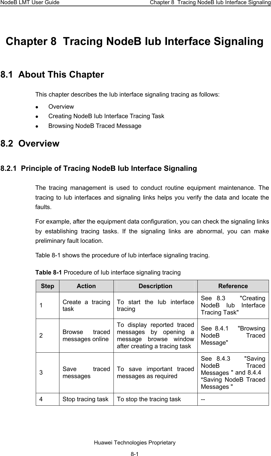
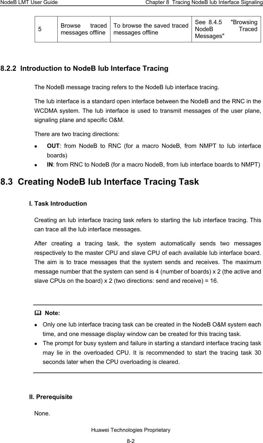
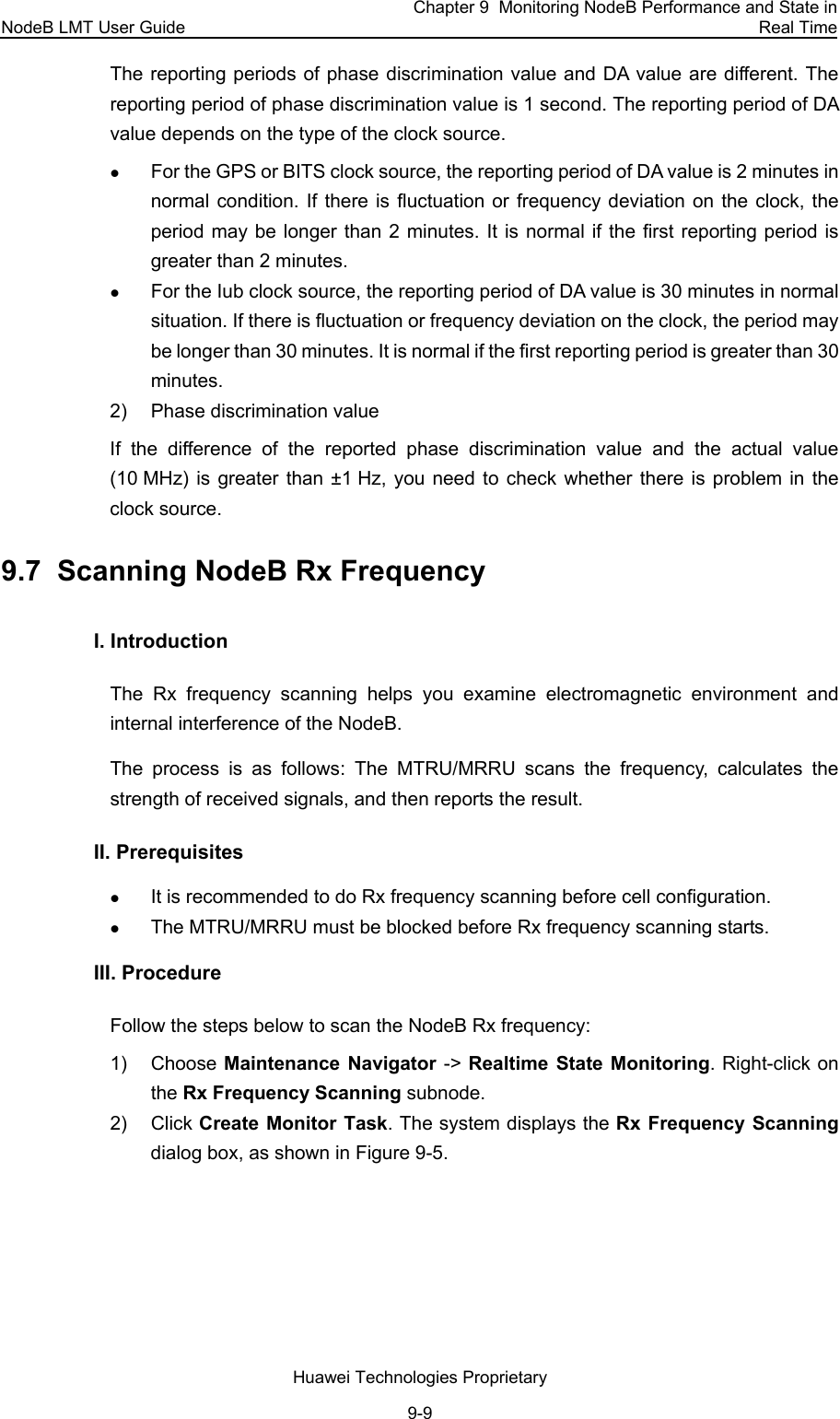
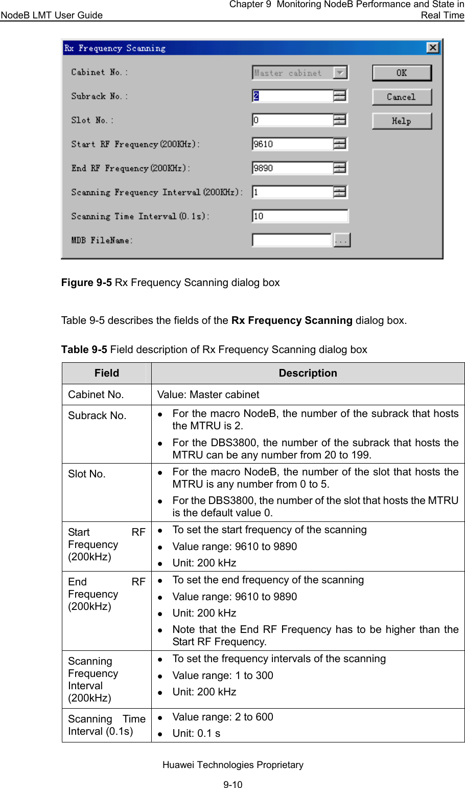
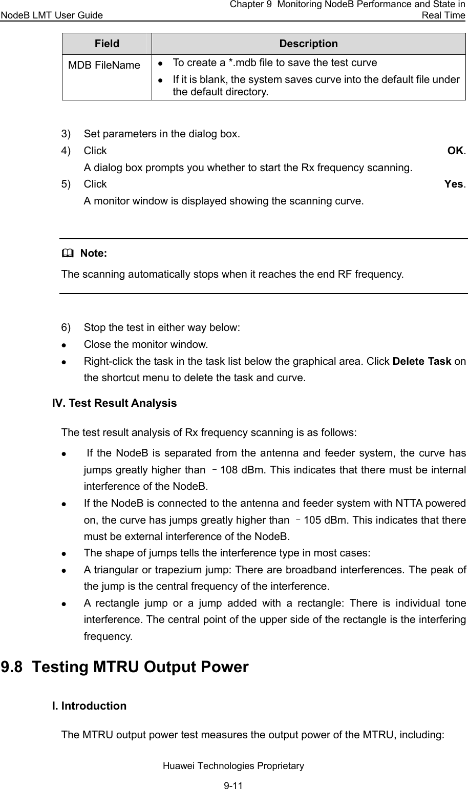
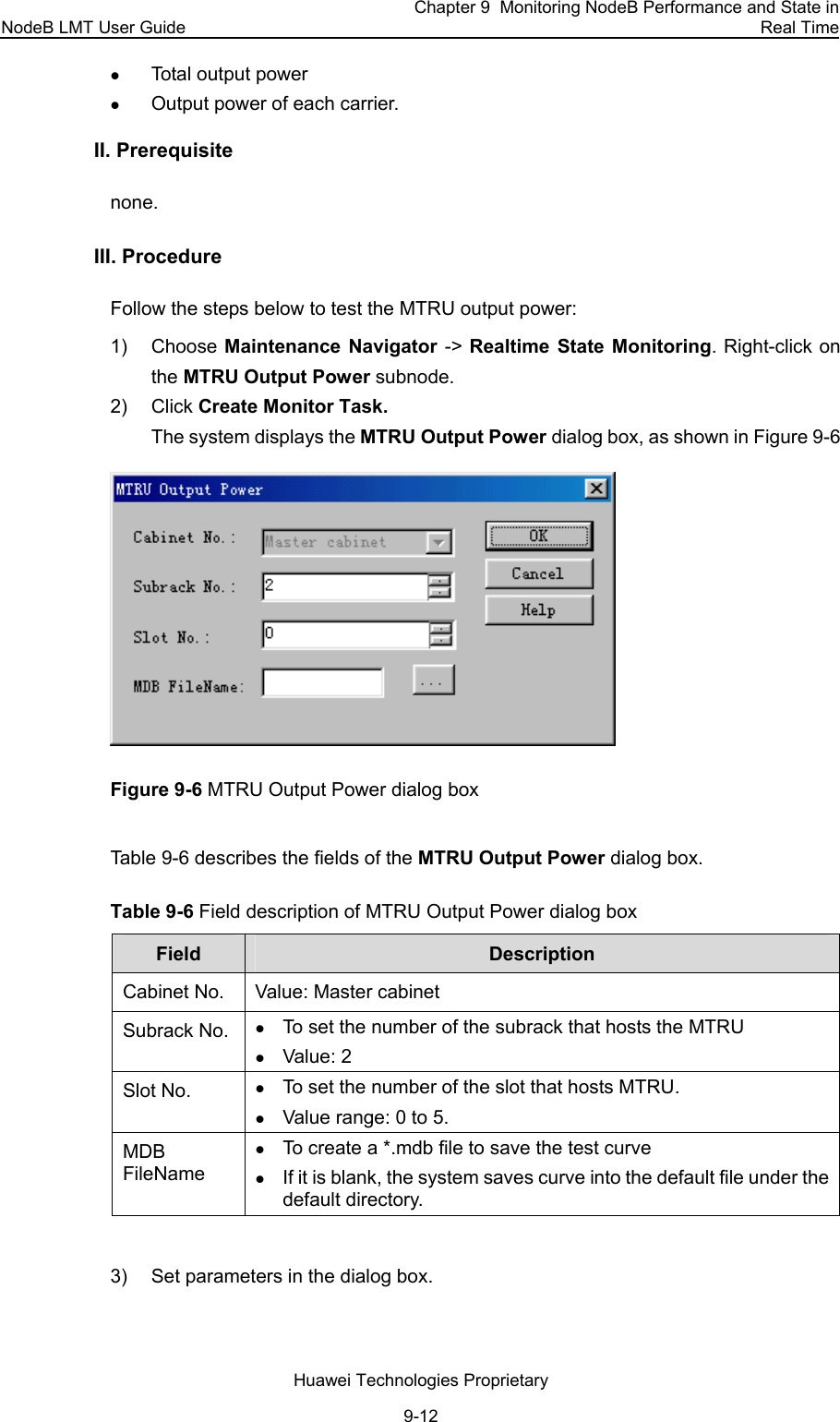
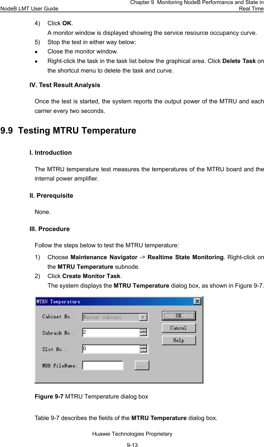
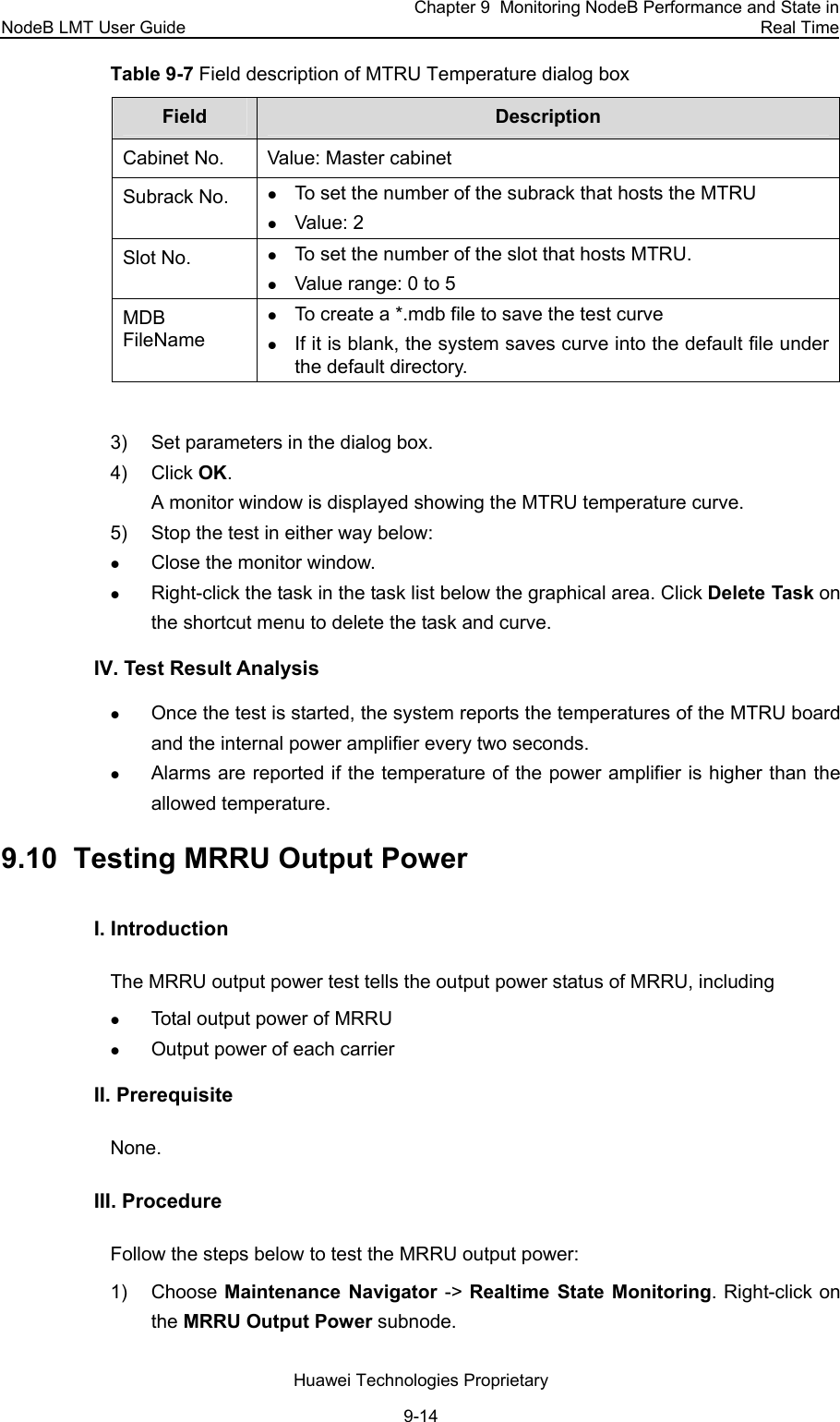
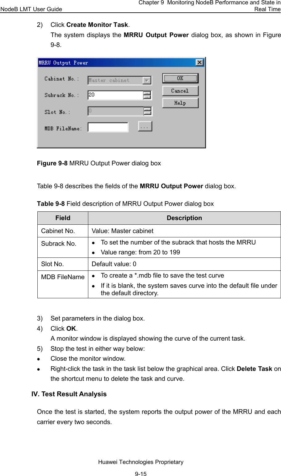
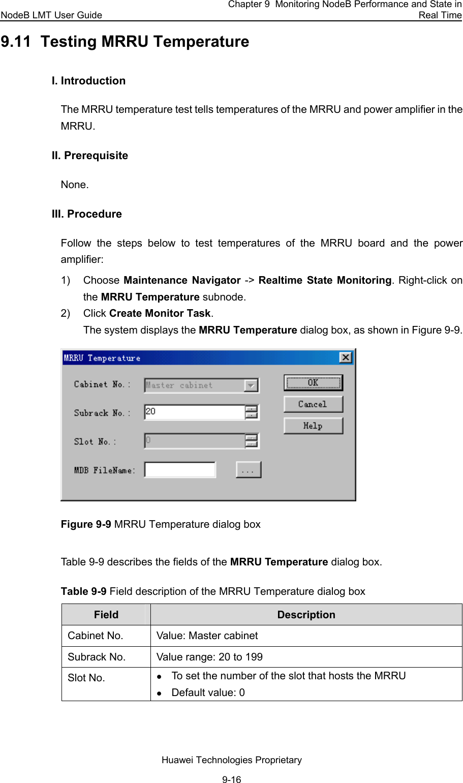
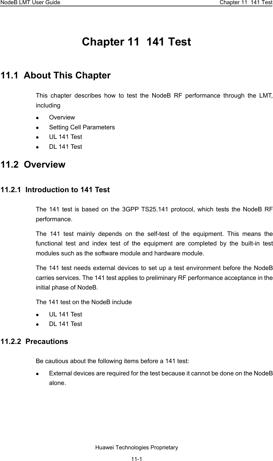
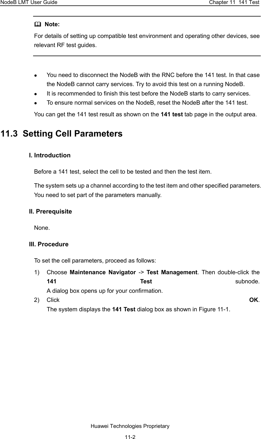
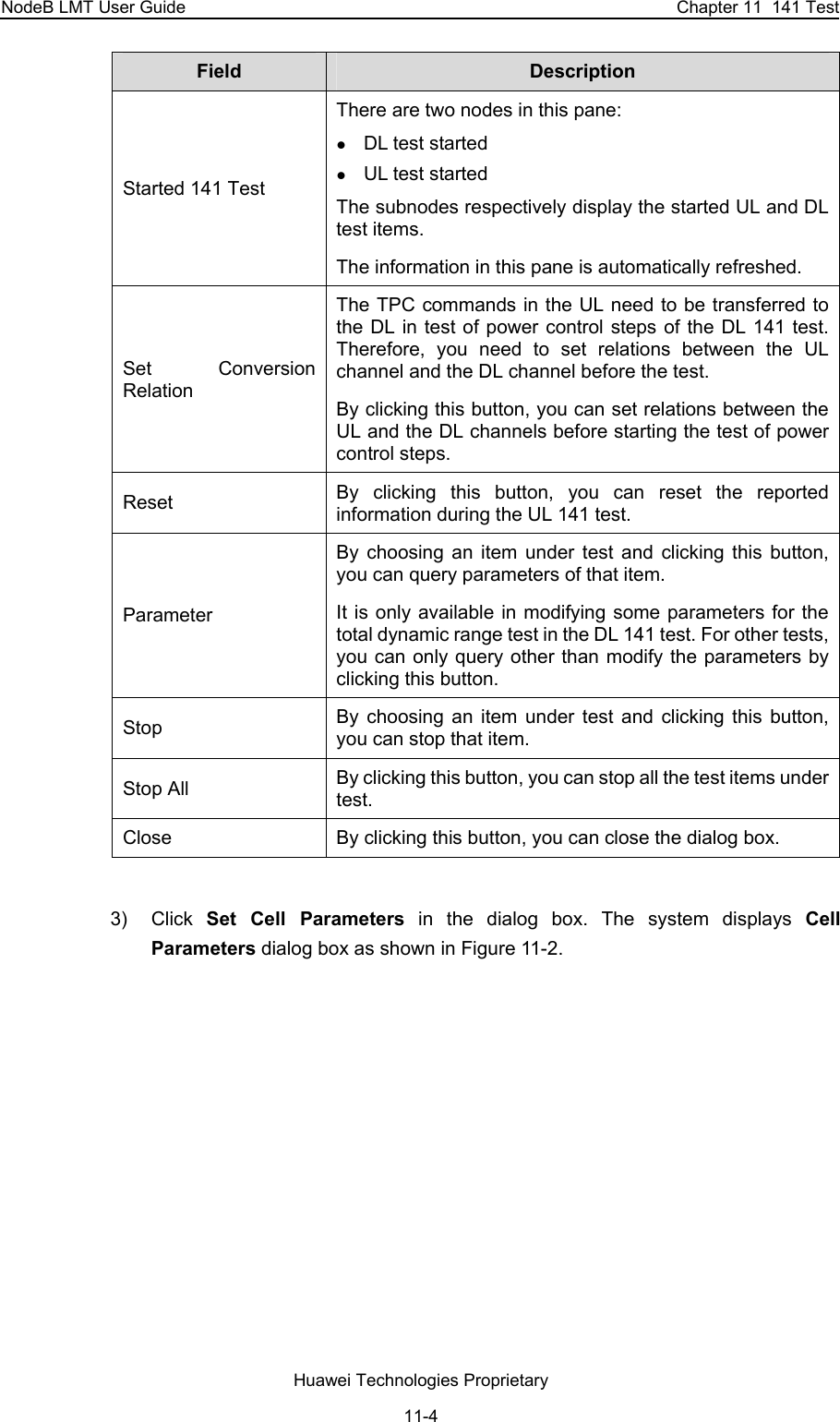
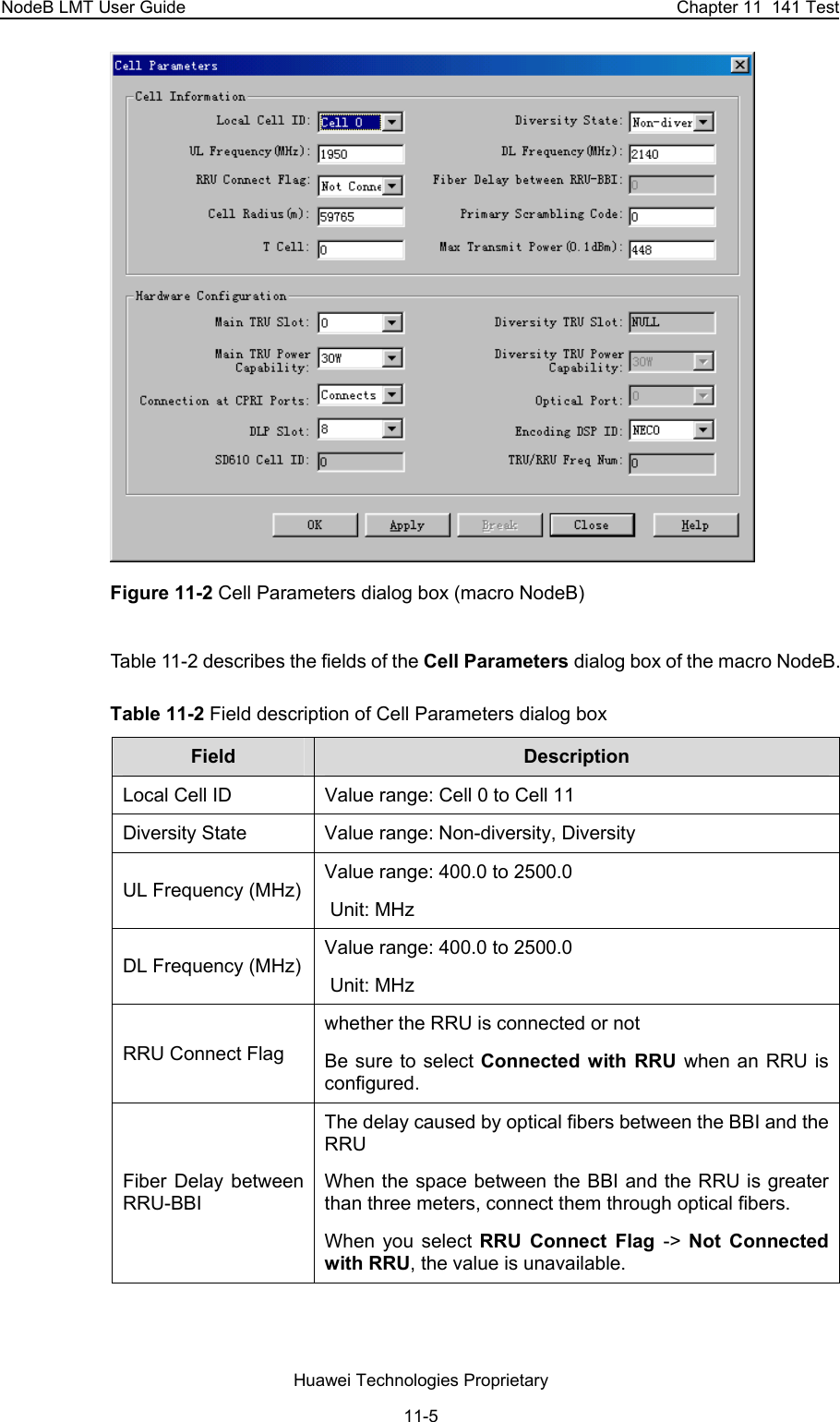
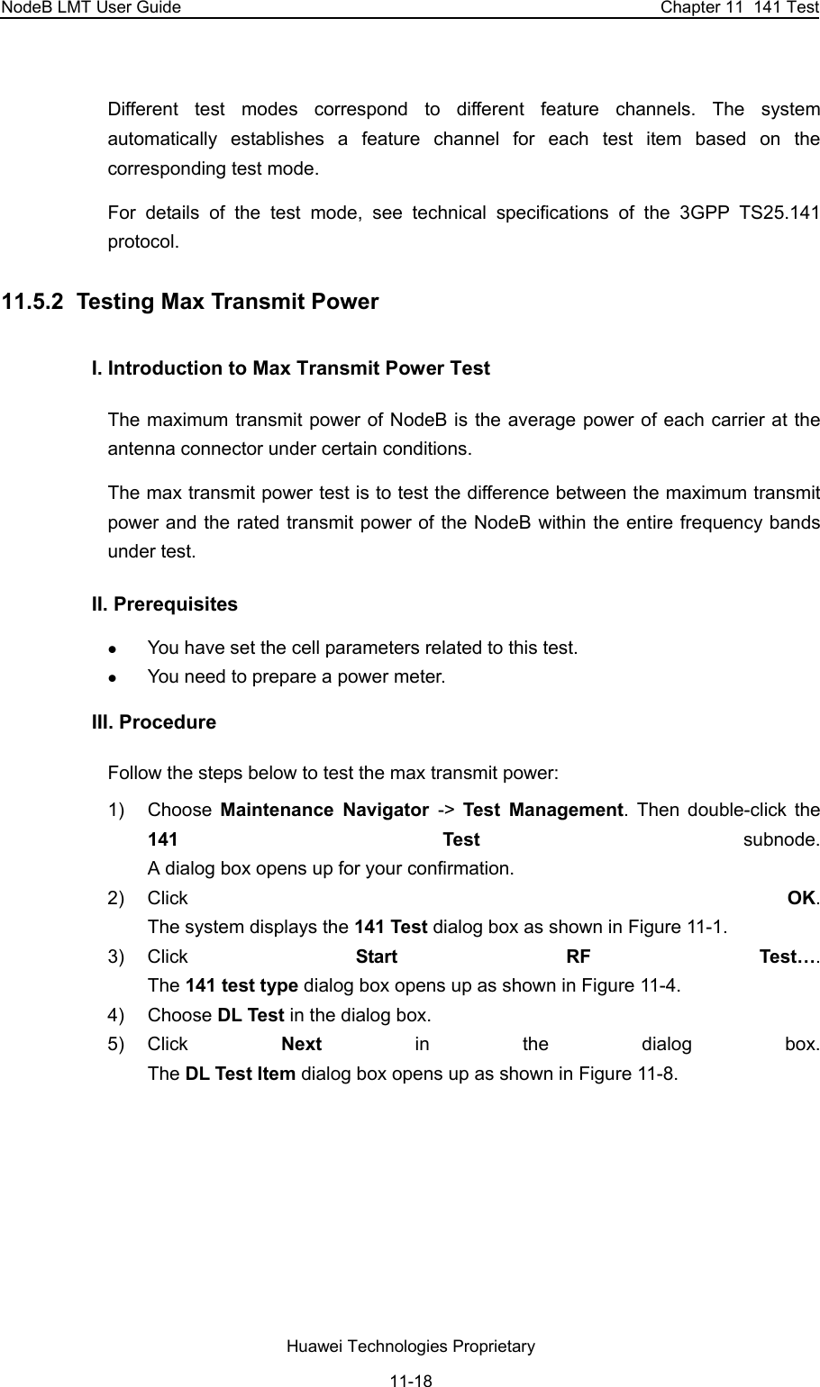
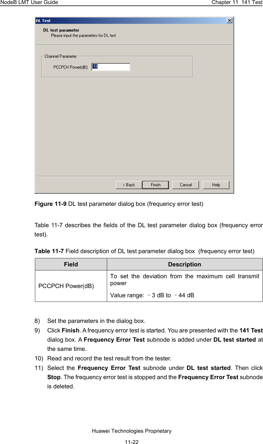
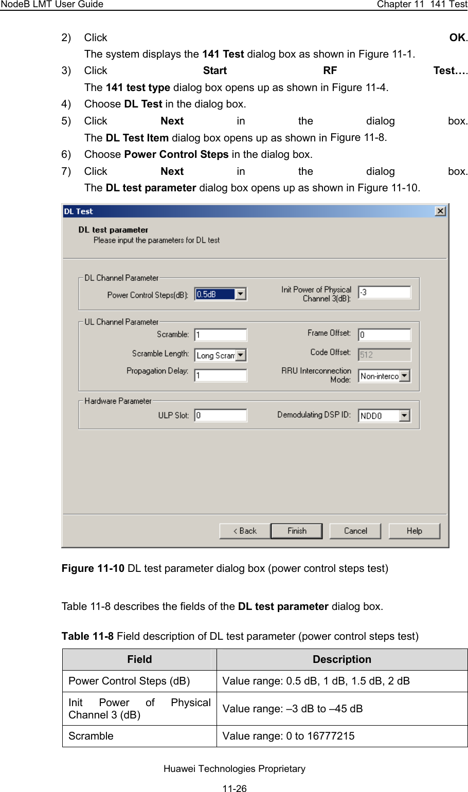
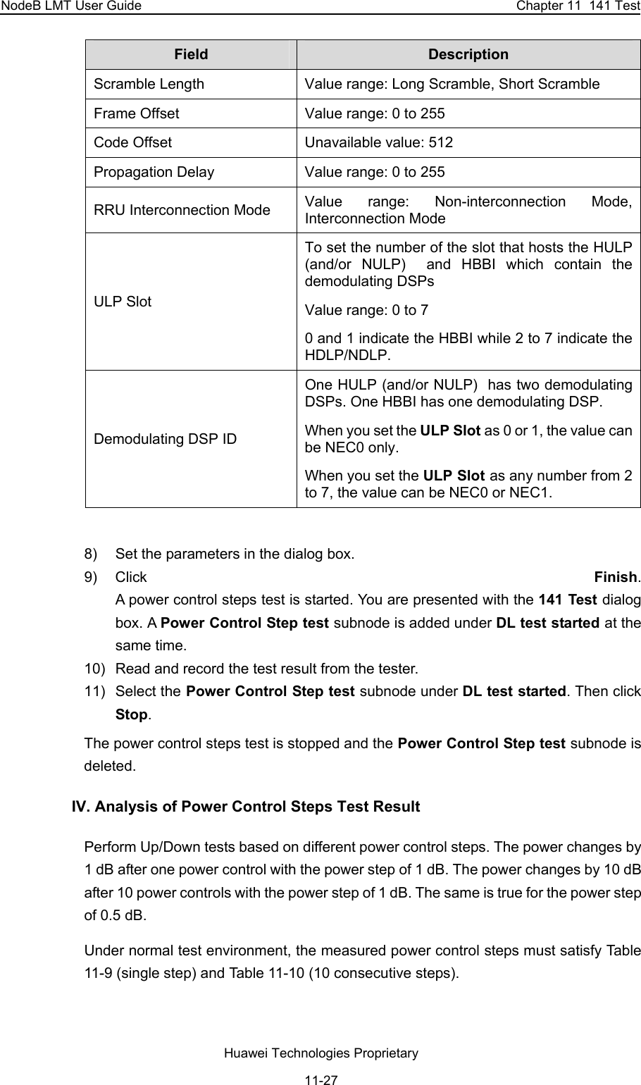
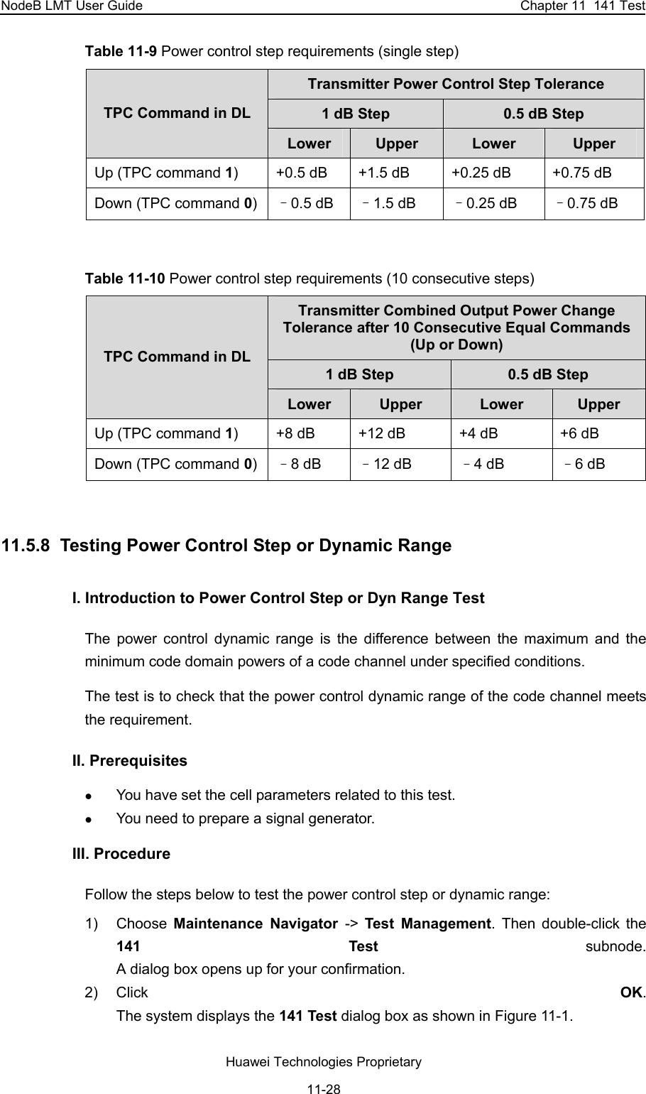
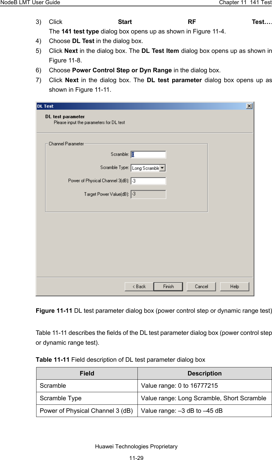
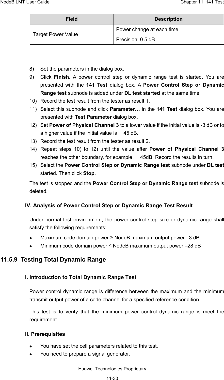
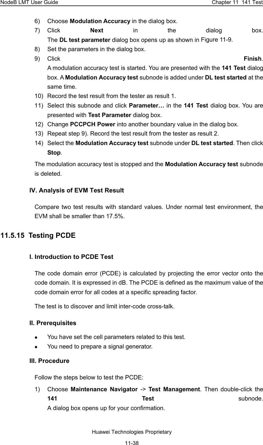
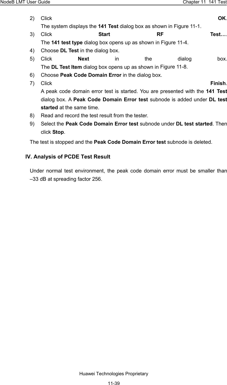
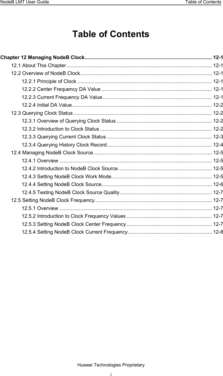
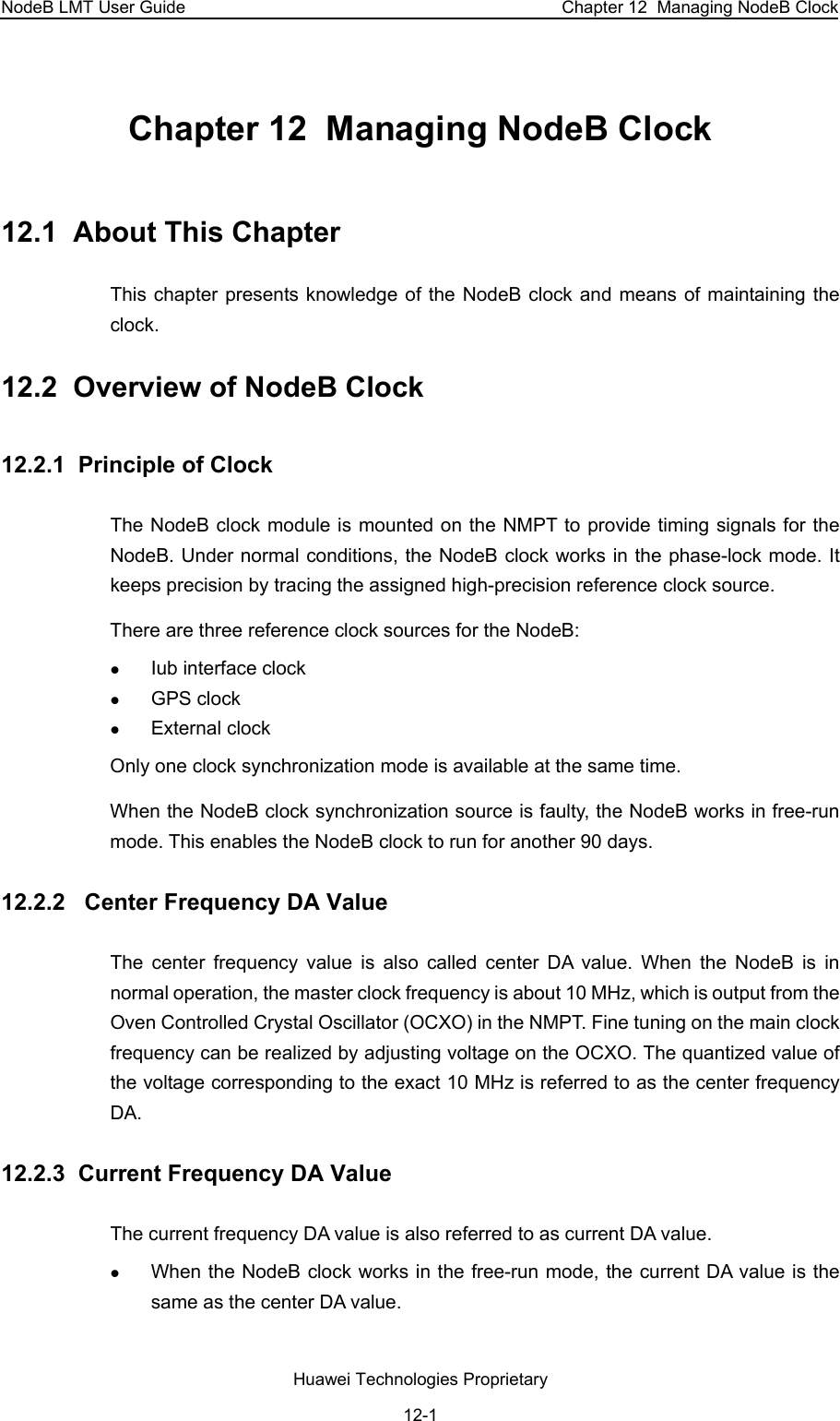
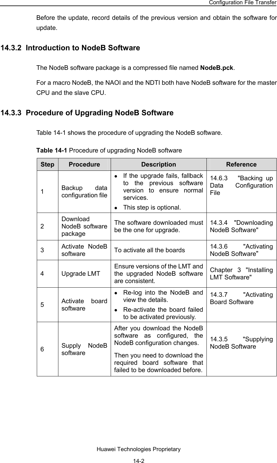
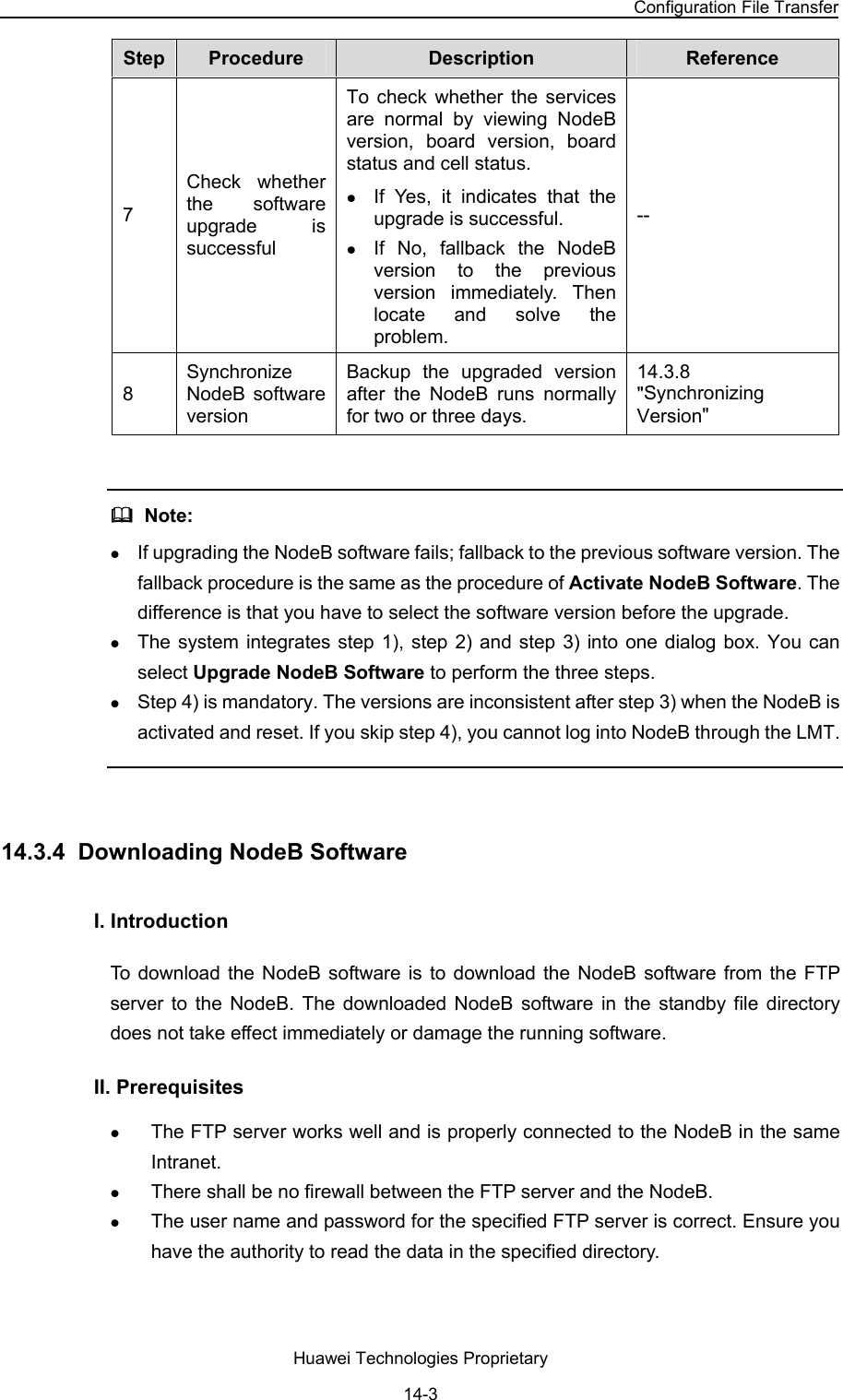
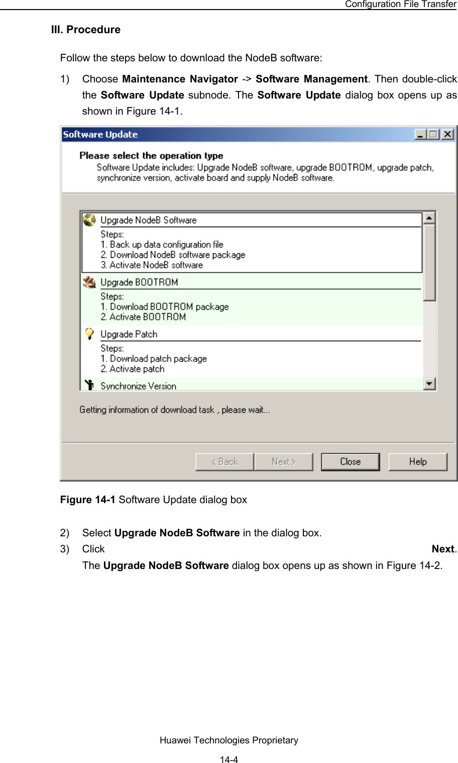
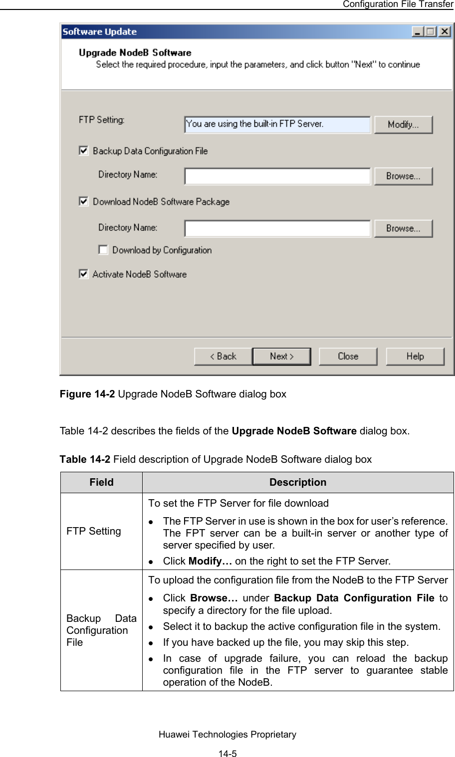
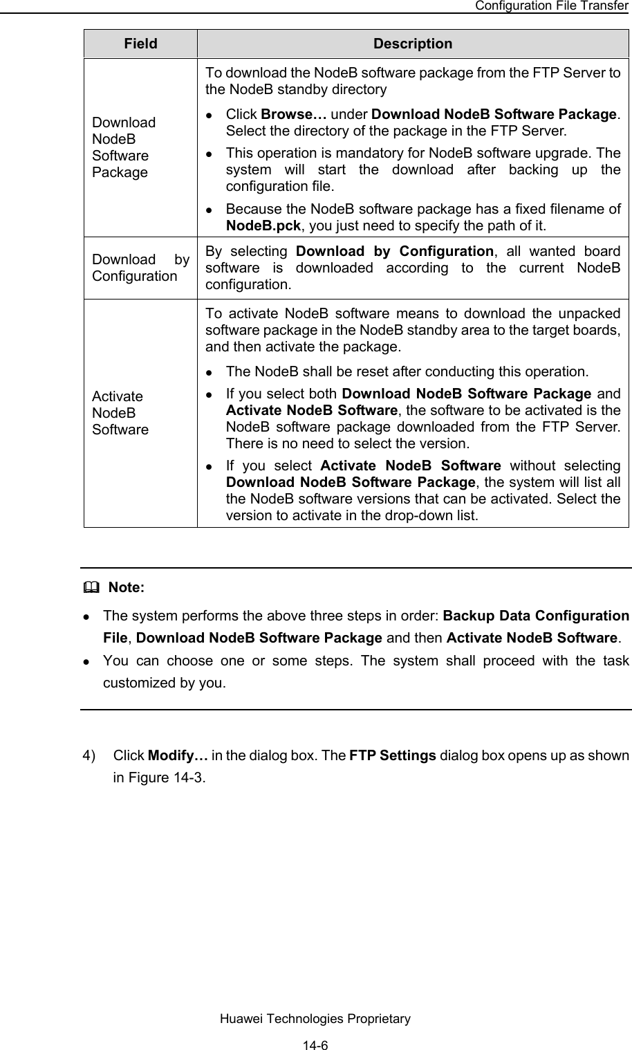
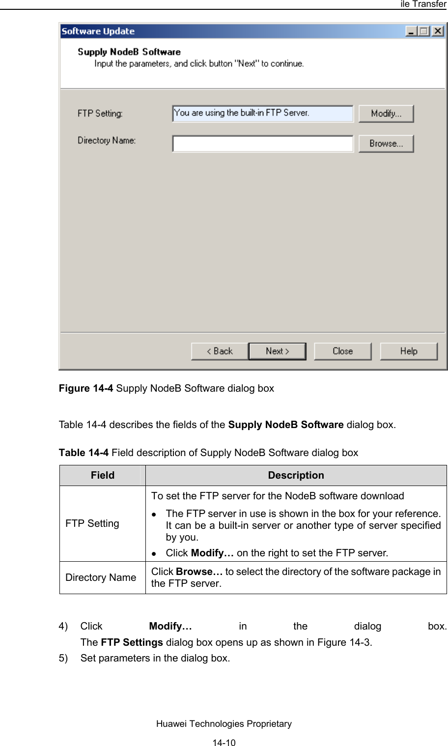
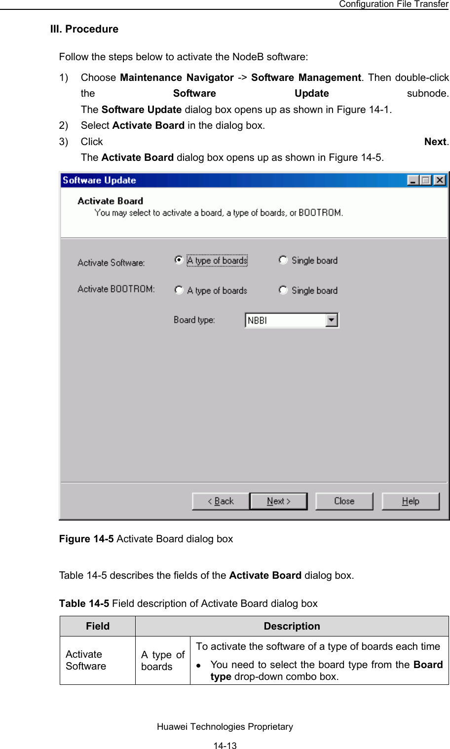
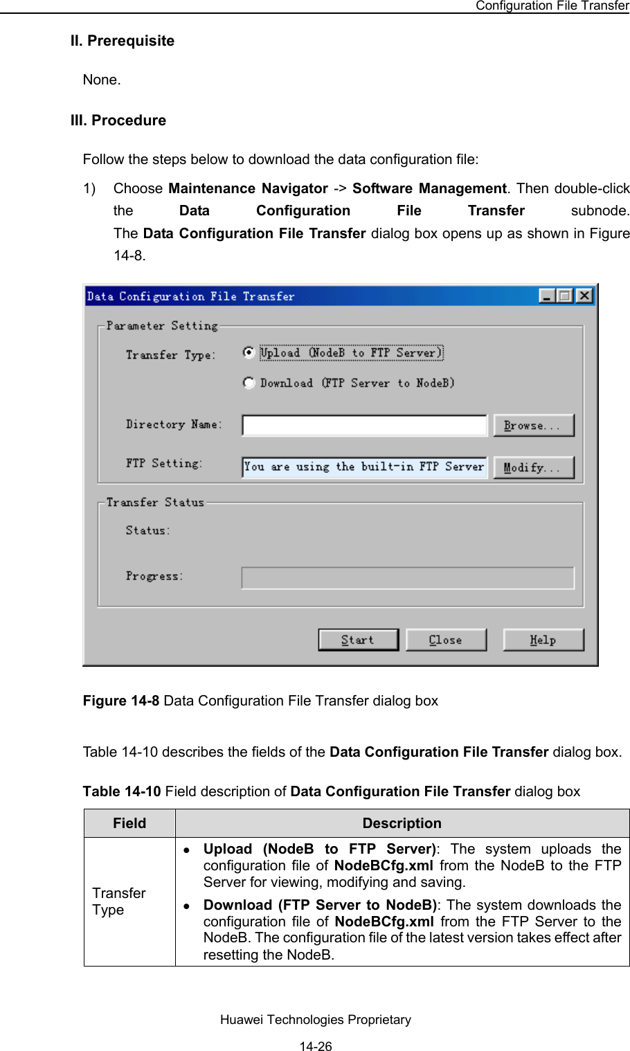
![NodeB LMT User Guide Chapter 8 Tracing NodeB Iub Interface Signaling 8.4.3 Saving NodeB Traced Messages Automatically I. Introduction z Saving traced messages automatically indicates the system saves the reported messages in the format of *.tmf into the Trace directory of the running NodeB. You can select another new path. z When a message file does not satisfy the save condition, a new message file is generated. All message files related to the task are associated through the Index value. When a file is created, index value will ascend until the task is terminated. The message file name takes the following format: office direction name_Interface type_YYYY-MM-DD_HH-MM-SS[_Index].tmf, where, z YYYY-MM-DD_HH-MM-SS shows the task creation time. z YYYY, MM, DD, HH, MM and SS stands for year, month, day, hour, minute and second respectively. z Index indicates multiple traced message files created in an interface tracing task. The index value ascends from 1. II. Prerequisite None. III. Procedure Follow the steps below to save the reported interface traced messages automatically: 1) Open the Standard Interface Tracing dialog box as shown in Figure 8-1. 2) Click Advanced. 3) Select Auto Save in the Advanced dialog box as shown in Figure 8-2. 8.4.4 Saving NodeB Traced Messages Manually I. Introduction You can choose to save selected or all traced messages. II. Prerequistie None. III. Procedure Follow the steps below to save the selected traced messages manually: 1) Right-click in the Standard Interface Tracing window. 2) Select Stop Task on the shortcut menu. Huawei Technologies Proprietary 8-9](https://usermanual.wiki/Huawei-Technologies/RRU3801C-19202.User-Manual-Part-2/User-Guide-626138-Page-9.png)