Huawei Technologies RRU3801C-19202 WCDMA Base Station User Manual 00 1 Cover
Huawei Technologies Co.,Ltd WCDMA Base Station 00 1 Cover
Contents
- 1. User Manual Part 1
- 2. User Manual Part 2
User Manual Part 2

NodeB LMT User Guide Chapter 8 Tracing NodeB Iub Interface Signaling
Chapter 8 Tracing NodeB Iub Interface Signaling
8.1 About This Chapter
This chapter describes the Iub interface signaling tracing as follows:
z Overview
z Creating NodeB Iub Interface Tracing Task
z Browsing NodeB Traced Message
8.2 Overview
8.2.1 Principle of Tracing NodeB Iub Interface Signaling
The tracing management is used to conduct routine equipment maintenance. The
tracing to Iub interfaces and signaling links helps you verify the data and locate the
faults.
For example, after the equipment data configuration, you can check the signaling links
by establishing tracing tasks. If the signaling links are abnormal, you can make
preliminary fault location.
Table 8-1 shows the procedure of Iub interface signaling tracing.
Table 8-1 Procedure of Iub interface signaling tracing
Step Action Description Reference
1 Create a tracing
task
To start the Iub interface
tracing
See 8.3 "Creating
NodeB Iub Interface
Tracing Task"
2 Browse traced
messages online
To display reported traced
messages by opening a
message browse window
after creating a tracing task
See 8.4.1 "Browsing
NodeB Traced
Message"
3 Save traced
messages
To save important traced
messages as required
See 8.4.3 "Saving
NodeB Traced
Messages " and 8.4.4
"Saving NodeB Traced
Messages "
4 Stop tracing task To stop the tracing task --
Huawei Technologies Proprietary
8-1

NodeB LMT User Guide Chapter 8 Tracing NodeB Iub Interface Signaling
5 Browse traced
messages offline
To browse the saved traced
messages offline
See 8.4.5 "Browsing
NodeB Traced
Messages"
8.2.2 Introduction to NodeB Iub Interface Tracing
The NodeB message tracing refers to the NodeB Iub interface tracing.
The Iub interface is a standard open interface between the NodeB and the RNC in the
WCDMA system. The Iub interface is used to transmit messages of the user plane,
signaling plane and specific O&M.
There are two tracing directions:
z OUT: from NodeB to RNC (for a macro NodeB, from NMPT to Iub interface
boards)
z IN: from RNC to NodeB (for a macro NodeB, from Iub interface boards to NMPT)
8.3 Creating NodeB Iub Interface Tracing Task
I. Task Introduction
Creating an Iub interface tracing task refers to starting the Iub interface tracing. This
can trace all the Iub interface messages.
After creating a tracing task, the system automatically sends two messages
respectively to the master CPU and slave CPU of each available Iub interface board.
The aim is to trace messages that the system sends and receives. The maximum
message number that the system can send is 4 (number of boards) x 2 (the active and
slave CPUs on the board) x 2 (two directions: send and receive) = 16.
Note:
z Only one Iub interface tracing task can be created in the NodeB O&M system each
time, and one message display window can be created for this tracing task.
z The prompt for busy system and failure in starting a standard interface tracing task
may lie in the overloaded CPU. It is recommended to start the tracing task 30
seconds later when the CPU overloading is cleared.
II. Prerequisite
None.
Huawei Technologies Proprietary
8-2
NodeB LMT User Guide Chapter 8 Tracing NodeB Iub Interface Signaling
III. Procedure
Follow the steps below to create a tracing task:
1) Choose Maintenance Navigator -> Tracing Management. Then double-click
Standard Interface Tracing subnode.
A prompt dialog box opens up.
Note:
You may clear the check box of Show tips at startup next time in the dialog box. This
dialog box does not appear when you start a tracing task next time.
2) Click Continue in the dialog box.
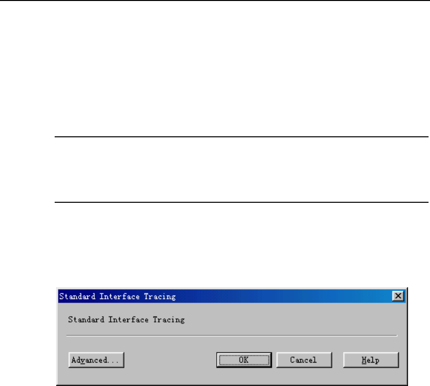
The Standard Interface Tracing dialog box opens up as shown in Figure 8-1.
Figure 8-1 shows the Standard Interface Tracing dialog box.
Figure 8-1 Standard Interface Tracing dialog box
3) Click Advanced….
The Advanced dialog box opens up as shown in Figure 8-2.
Huawei Technologies Proprietary
8-3
NodeB LMT User Guide Chapter 8 Tracing NodeB Iub Interface Signaling
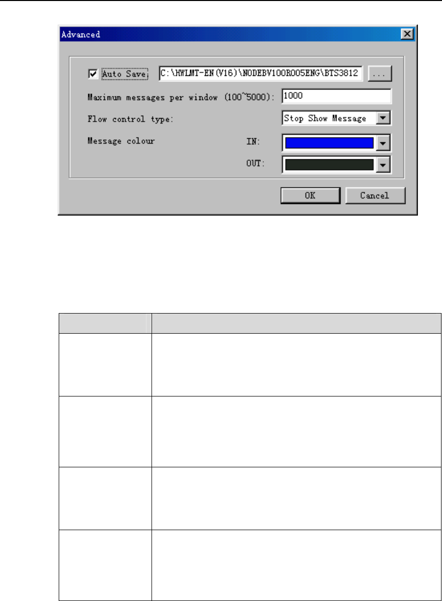
Figure 8-2 Advanced dialog box
Table 8-1 describes the fields of the Advanced dialog box.
Table 8-2 Field description of Advanced dialog box
Field Description
Auto Save
Select Auto Save. The system saves reported messages in the
Trace directory of the running version by default. You may
modify the saving directory.
Each reported message is to be saved in the message file.
Maximum
messages per
window
To set the maximum number of messages displayed in the
message browse window
Range: 100 to 5000
Default value: 1000
Flow control type
Stop Show Message: If the message flow is too large, the
system stops displaying messages on the interface.
Stop Trace Task: If the message flow is too large, the system
stops the tracing task.
Message colour
To set the display colors of messages in two directions
z IN: from RNC to NodeB
z OUT: from NodeB to RNC
Both directions have 16 optional colors.
4) Set parameters in the Advanced dialog box.
5) Click OK.
You are presented with the Standard Interface Tracing window as shown in
Figure 8-3.
Huawei Technologies Proprietary
8-4
NodeB LMT User Guide Chapter 8 Tracing NodeB Iub Interface Signaling
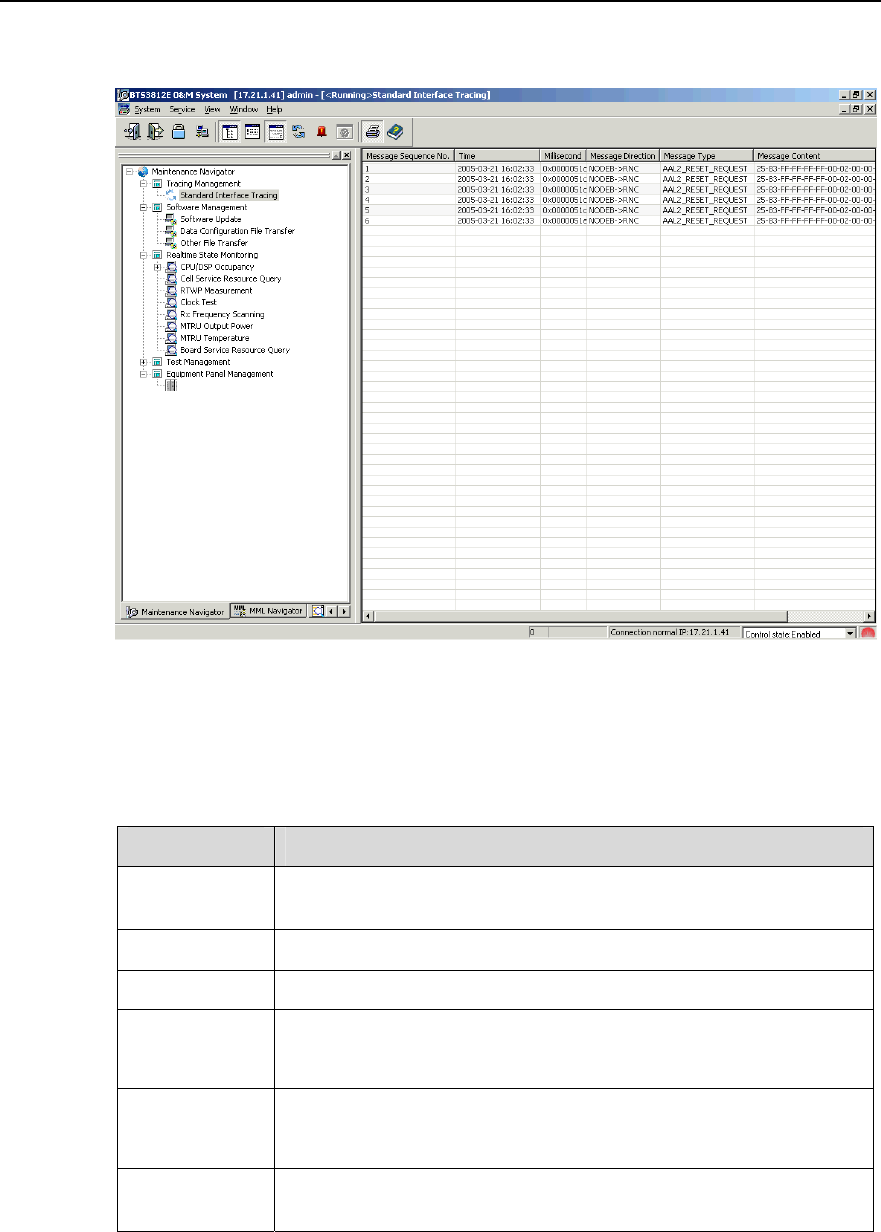
Figure 8-3 shows the Standard Interface Tracing window.
Figure 8-3 Standard Interface Tracing window
Table 8-3 describes the fields of the Standard Interface Tracing window.
Table 8-3 Fields in the Standard Interface Tracing window
Field Description
Message
Sequence No. Sequence number of the message by arrival time
Time Message arrival time in the format of YYYY-MM-DD HH:MM:SS
Millisecond Traced message reporting interval: 100 ms
Message
Direction
RNC->NodeB: from RNC to NodeB
NodeB->RNC: from NodeB to RNC
Message Type
NBAP messages starting with NBAP_
ALCAP messages starting with ALL2_
Message
Content
The system translates the message contents displayed in binary
into message codes according to the message type.
Huawei Technologies Proprietary
8-5

NodeB LMT User Guide Chapter 8 Tracing NodeB Iub Interface Signaling
8.4 Browsing NodeB Traced Message
8.4.1 Browsing NodeB Traced Message Online
I. Introduction
When you create a tracing task, the system starts a message browse window and
displays the reported traced messages. The message browse window displays the
traced messages in columns and adds messages in sequential order in real time.
II. Prerequisite
None.
III. Procedure
Follow the steps below to browse traced messages:
1) Create a tracing task.
For details, see 8.3 “Creating NodeB Iub Interface Tracing Task”.
2) Double-click a message in the Standard Interface Tracing window.
The message explanation window opens up as shown in Figure 8-4.
Figure 8-4 lists details in the message explanation window.
Huawei Technologies Proprietary
8-6
NodeB LMT User Guide Chapter 8 Tracing NodeB Iub Interface Signaling
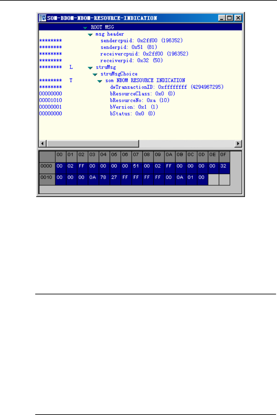
Figure 8-4 Message explanation window
The upper part of the window shows the explanation of the message and the lower part
shows the source code.
3) Click the Close button on the upper right corner of the window.
The Standard Interface Tracing window and the message explanation
window are closed.
Note:
z To clear all message records in the window, right-click in the Standard Interface
Tracing window, and select Clear All on the shortcut menu. The system clears all
the message records from the list and displays the traced messages reported
afterwards from the first line.
z If you double-click another message with the message explanation window open,
the system does not generate a new message explanation window but refreshes the
explanations. The system explains only one message each time.
z If you double-click multiple messages selected, the system explains the one clicked
only.
z For more detailed message explanations, see relevant interface protocol.
Huawei Technologies Proprietary
8-7
NodeB LMT User Guide Chapter 8 Tracing NodeB Iub Interface Signaling
8.4.2 Setting Browsing Properties of NodeB Traced Message
I. Introduction
The following functions enable you to browse messages in the Standard Interface
Tracing window:
z Setting traced message color: When you create a tracing task, the system
displays the traced results in different colors according to their transmission
directions. IN is the color for messages from RNC to NodeB while OUT is the color
for messages from NodeB to RNC. You can modify the value of IN and OUT.
z Setting message window scroll: It is used to set whether to scroll the window.
z Setting message filter: For the unimportant but frequently reported messages, you
may choose to filter them.
II. Prerequisite
None.
III. Procedure
Follow the steps below to set traced message display:
1) Right-click in the Standard Interface Tracing window.
2) Select relevant menus on the shortcut menu.
Table 8-4 shows how to set the browsing properties of the NodeB traced message.
Table 8-4 Description of setting browsing properties of NodeB traced message
Property Shortcut menu Description
Traced message
color setting
Modify Color
Settings
You can also set the message color
when creating an Iub interface tracing
task. See 8.3 “Creating NodeB Iub
Interface Tracing Task”.
Message window
scroll setting Automatic Scroll --
Message Filter
setting Filter --
Huawei Technologies Proprietary
8-8

NodeB LMT User Guide Chapter 8 Tracing NodeB Iub Interface Signaling
8.4.3 Saving NodeB Traced Messages Automatically
I. Introduction
z Saving traced messages automatically indicates the system saves the reported
messages in the format of *.tmf into the Trace directory of the running NodeB. You
can select another new path.
z When a message file does not satisfy the save condition, a new message file is
generated. All message files related to the task are associated through the Index
value. When a file is created, index value will ascend until the task is terminated.
The message file name takes the following format: office direction name_Interface
type_YYYY-MM-DD_HH-MM-SS[_Index].tmf, where,
z YYYY-MM-DD_HH-MM-SS shows the task creation time.
z YYYY, MM, DD, HH, MM and SS stands for year, month, day, hour, minute and
second respectively.
z Index indicates multiple traced message files created in an interface tracing task.
The index value ascends from 1.
II. Prerequisite
None.
III. Procedure
Follow the steps below to save the reported interface traced messages automatically:
1) Open the Standard Interface Tracing dialog box as shown in Figure 8-1.
2) Click Advanced.
3) Select Auto Save in the Advanced dialog box as shown in Figure 8-2.
8.4.4 Saving NodeB Traced Messages Manually
I. Introduction
You can choose to save selected or all traced messages.
II. Prerequistie
None.
III. Procedure
Follow the steps below to save the selected traced messages manually:
1) Right-click in the Standard Interface Tracing window.
2) Select Stop Task on the shortcut menu.
Huawei Technologies Proprietary
8-9

NodeB LMT User Guide Chapter 8 Tracing NodeB Iub Interface Signaling
3) Select the traced messages to be saved. Shortcut keys of Ctrl and Shift are
applicable.
4) Right-click on the messages and select Save Selected Record on the
shortcut menu.
5) Specify a path and name for the file.
6) Click Save.
Follow the steps below to save all the traced messages manually:
1) Right-click in the Standard Interface Tracing window.
2) Select Save All Records on the shortcut menu.
3) Specify a path and name for the file.
4) Click Save.
8.4.5 Browsing NodeB Traced Messages Offline
I. Introduction
You can browse message files (*.tmf) offline with the TraceViewer.
II. Prerequisite
There are message files automatically saved by the system and manually saved by
you.
III. Procedure
Follow the steps below to view traced messages offline:
1) Select Service -> TraceViewer in the NodeB O&M system, or click the
shortcut icon .
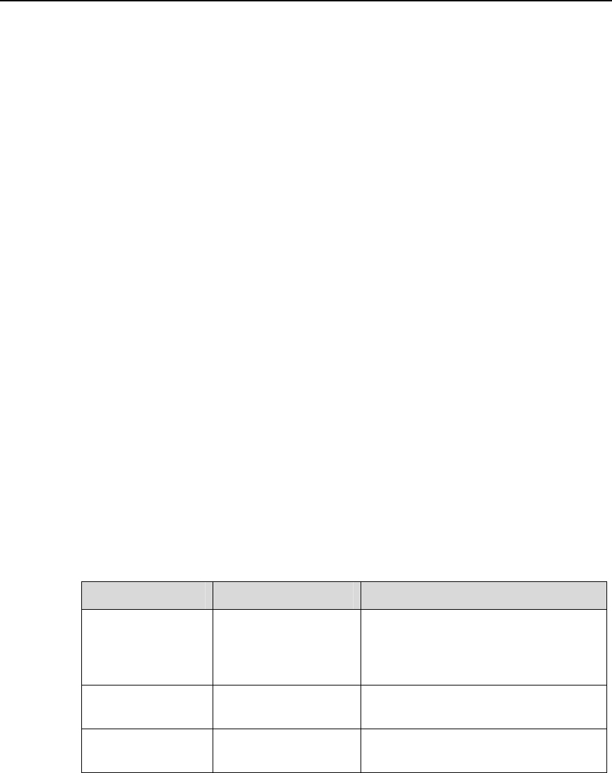
2) Select the relevant NodeB version in the Select Version dialog box as shown
in Figure 8-5.
Huawei Technologies Proprietary
8-10
NodeB LMT User Guide Chapter 8 Tracing NodeB Iub Interface Signaling
Figure 8-5 Select Version dialog box
3) Click OK and start the TraceViewer.
4) Select the message file to be browsed in the Open dialog box.
5) Click OK.
The TraceViewer window is displayed.
6) Double-click a message record in the window.
You are presented with the explanations of it.
Note:
You can carry out the following actions with the NodeB TraceViewer:
z To save the selected messages to a message file, right-click on the message
records and then select Save Selected Record on the shortcut menu.
z Click different buttons on the title bar. Then the messages shall be sequenced
according to message number, time, direction or type.
z To filter the messages, right-click the mouse and then select Filter or Filter on
Column on the shortcut menu. See section 8.4.6 "Filtering NodeB Traced
Messages ".
7) Select File -> Exit.
Huawei Technologies Proprietary
8-11
NodeB LMT User Guide Chapter 8 Tracing NodeB Iub Interface Signaling
The message browse window is closed.
8.4.6 Filtering NodeB Traced Messages
I. Introduction
The filtering traced messages function enables you to filter out unwanted messages.
There are two ways for filtering messages:
z Filtering messages with customized conditions: you can filter out unwanted
messages according to one or more conditions by defining the filter.
z Filtering messages on column: You can filter out unwanted messages according to
the property of a column.
II. Prerequisite
None.
III. Procedure
Follow the steps below to define filters:
1) Select Operate -> Filter… after opening a message tracing file, or right-click
in an open message tracing file and then select Filter on the shortcut menu.
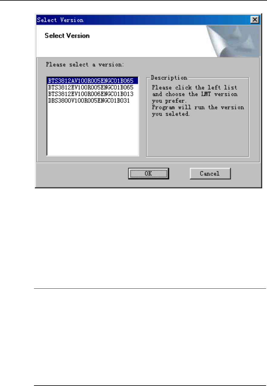
2) Click New… in the Filter dialog box as shown in Figure 8-6.
Figure 8-6 Filter dialog box
Huawei Technologies Proprietary
8-12
NodeB LMT User Guide Chapter 8 Tracing NodeB Iub Interface Signaling
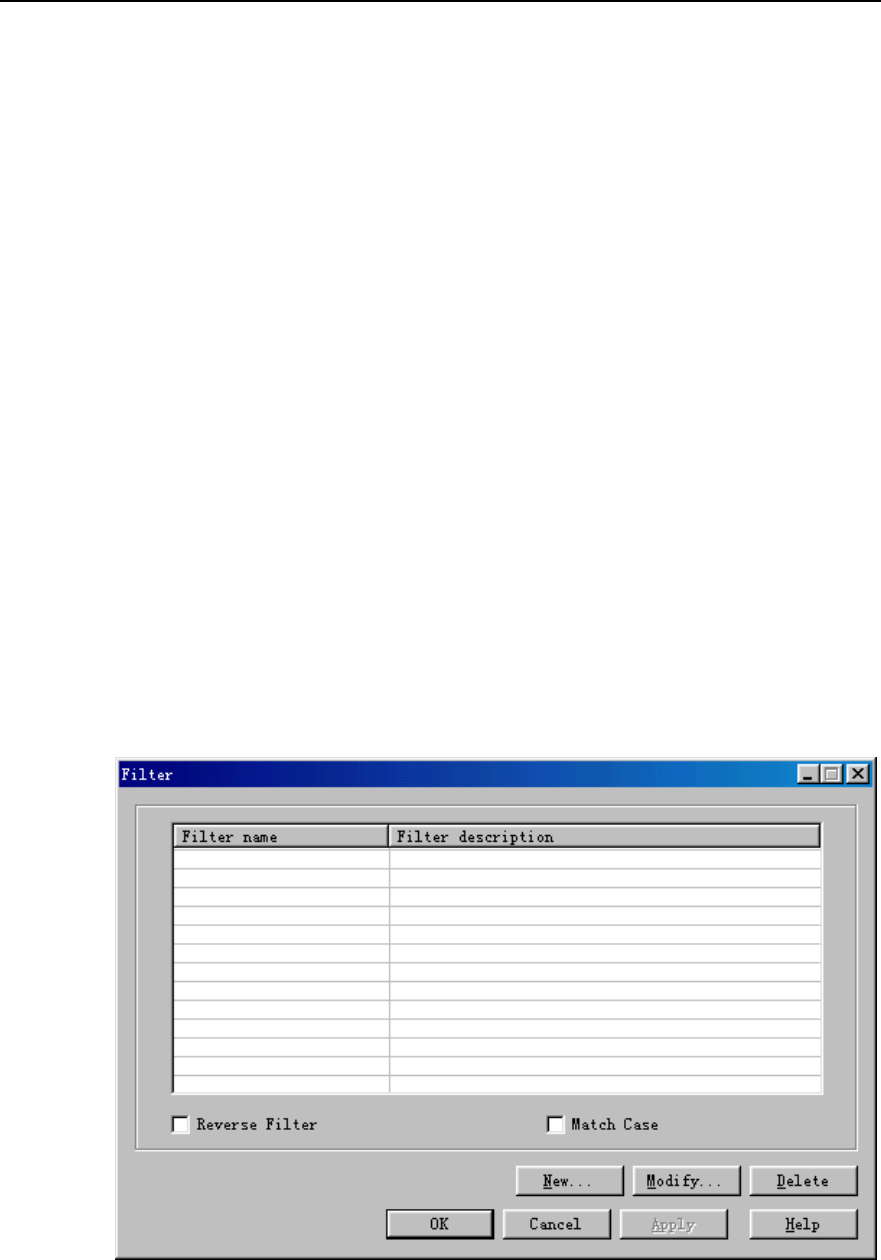
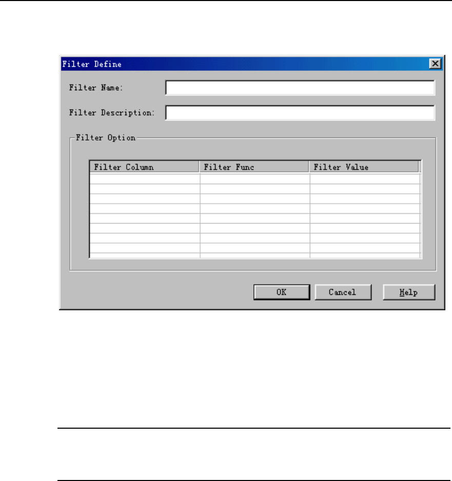
3) Set one or more filtering conditions in the Filter Define dialog box as shown in
Figure 8-7.
Figure 8-7 Filter Define dialog box
4) Click OK.
You are presented with the Filter dialog box.
5) Select the defined filter and then click Apply.
Note:
To perform invert filtering, select Reverse Filter in the Filter dialog box
Follow the steps below to filter messages on column:
1) Open a message file and then select a column of message records to be
filtered.
2) Right-click on the column.
3) Select Filter on Column on the shortcut menu.
4) Choose a message property in the drop-down list of the Column Filter dialog
box.
5) Click OK.
You may cancel the message filtering as follows:
z Choose Operate -> Cancel Filter, or
Huawei Technologies Proprietary
8-13

NodeB LMT User Guide Chapter 8 Tracing NodeB Iub Interface Signaling
z Right-click in the TraceViewer window and then select Cancel Filter on the
shortcut menu.
The system displays all messages in the message file.
Huawei Technologies Proprietary
8-14

NodeB LMT User Guide Table of Contents
Table of Contents
Chapter 9 Monitoring NodeB Performance and State in Real Time......................................... 9-1
9.1 About This Chapter............................................................................................................ 9-1
9.2 Overview ............................................................................................................................ 9-1
9.3 Querying CPU/DSP Occupancy ........................................................................................ 9-1
9.4 Querying Cell Service Resource........................................................................................ 9-3
9.5 Testing NodeB RTWP ....................................................................................................... 9-5
9.6 Testing NodeB Clock ......................................................................................................... 9-7
9.7 Scanning NodeB Rx Frequency ........................................................................................ 9-9
9.8 Testing MTRU Output Power........................................................................................... 9-11
9.9 Testing MTRU Temperature ............................................................................................ 9-13
9.10 Testing MRRU Output Power ........................................................................................ 9-14
9.11 Testing MRRU Temperature.......................................................................................... 9-16
9.12 Querying Board Service Resource ................................................................................ 9-17
9.13 Routine Testing NodeB E1/T1 Performance ................................................................. 9-19
9.14 Routine Testing STM-1 Performance ............................................................................ 9-20
Huawei Technologies Proprietary
i

NodeB LMT User Guide
Chapter 9 Monitoring NodeB Performance and State in
Real Time
Huawei Technologies Proprietary
9-1
Chapter 9 Monitoring NodeB Performance and
State in Real Time
9.1 About This Chapter
This chapter describes how to monitor the NodeB performance and state through the
LMT.
9.2 Overview
The NodeB supports the following performance tests:
z Querying CPU/DSP Occupancy
z Querying Cell Service Resource
z Testing NodeB RTWP
z Testing NodeB Clock
z Scanning NodeB Rx Frequency
z Testing MTRU Output Power
z Testing MTRU Temperature
z Testing MRRU Output Power
z Testing MRRU Temperature
z Querying Board Service Resource
z Routine Testing NodeB E1/T1
z Routine Testing STM-1
9.3 Querying CPU/DSP Occupancy
I. Introduction
The CPU/DSP occupancy shows the use of system resources.
II. Prerequisite
None.
III. Procedure
NodeB LMT User Guide
Chapter 9 Monitoring NodeB Performance and State in
Real Time
Huawei Technologies Proprietary
9-2
Caution:
This test cannot be applied to the NFCB, NEMU, GPSRCV or MAFU.
Follow the steps below to test CPU/DSP occupancy:
1) Choose Maintenance Navigator -> Realtime State Monitoring. Right-click on
the CPU/DSP Occupancy subnode.
2) ClickCreate Monitor Task.
3) The system displays the CPU/DSP Occupancy dialog box, as shown in Figure
9-1.
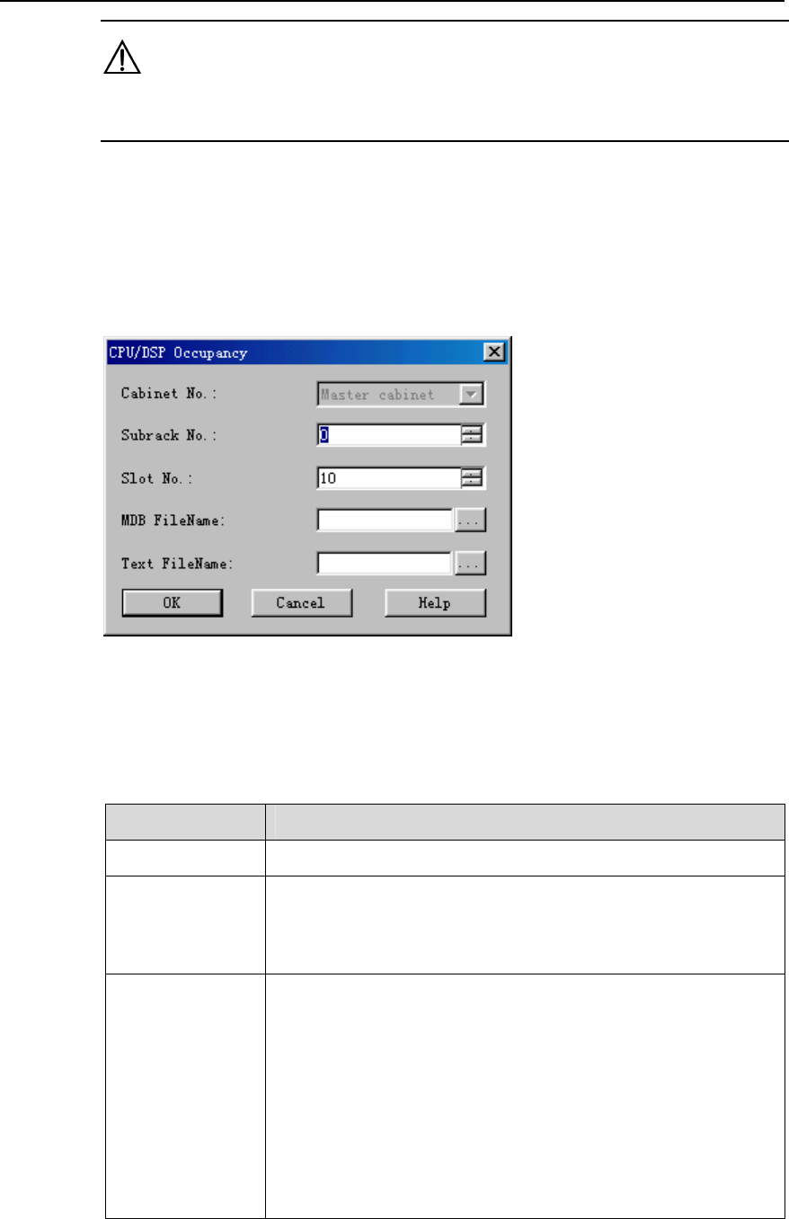
Figure 9-1 CPU/DSP Occupancy dialog box
Table 9-2 describes the fields in the CPU/DSP Occupancy dialog box.
Table 9-1 Field description of CPU/DSP Occupancy dialog box
Field Description
Cabinet No. Value: Master cabinet
Subrack No. z For the macro NodeB, the baseband subrack number is 0
while the MTRU subrack number is 2.
z For the DBS3800, the MRRU subrack number is any value
from 20 to 199.
Slot No. To set the number of the slot that hosts the board
z For the macro NodeB, the slot number of a board in the
baseband subrack can be 16 or any number from 0 to13.
z For the DBS3800, the slot number of the MRRU subrack
board is 0 by default.
The NDTI/NAOI has two CPUs: CPU0 (master CPU) and CPU1
(slave CPU). Any other board has only one CPU.
The HULP/NULP has four DSPs. The HDLP/NDLP has three
DSPs. The HBBI has four DSPs. All others have no DSP.

NodeB LMT User Guide
Chapter 9 Monitoring NodeB Performance and State in
Real Time
Huawei Technologies Proprietary
9-3
MDB FileName z To create a *.mdb file to save the test curve
z If it is blank, the system saves the test curve into the default
file under the default directory.
Text FileName z To create a *.txt file to save the test data
z If it is blank, the system will not save the data.
4) Set parameters in the dialog box.
5) Click OK. A monitor window is displayed showing the CPU/DSP occupancy curve.
6) Stop the test in either way below:
z Close the monitor window.
z Right-click the task in the task list below the graphical area. Then click Delete
Task on the shortcut menu.
IV. Test Result Analysis
1) Analysis of CPU occupancy test results
z When the NodeB works well without carrying services, the CPU occupancy of all
boards shall stay between 5% and 10%.
z The CPU occupancy increases when the NodeB carries services. The occupancy
of all boards shall be smaller than 75%. The system reports alarms if the
occupancy is greater than 75%.
z It is normal for the CPU occupancy to stay at 100% for a few seconds. However, if
the CPU occupancy stays at 100% for more than one minute while the NodeB
does not carry services, the CPU is faulty.
2) Analysis of DSP occupancy test results
None.
Note:
z You can open and query the text file that saves the CPU/DSP occupancy test
results.
z The corresponding board is presented at the beginning of the file. The occupancy of
all CPUs and DSPs under test at one time are recorded in one row with the test time.
9.4 Querying Cell Service Resource
I. Introduction
The cell service resource query shows the use of service resources of the cell in real
time. It includes:
NodeB LMT User Guide
Chapter 9 Monitoring NodeB Performance and State in
Real Time
Huawei Technologies Proprietary
9-4
z Number of UEs
z Number of idle HULP CEs
z Number of HULP CEs in use
z Number of idle HDLP CEs
z Number of HDLP CEs in use
II. Prerequisite
None.
III. Procedure
Follow the steps below to query the cell service resource:
1) Choose Maintenance Navigator -> Realtime State Monitoring. Right-click on
the Cell Service Resource Query subnode.
2) Click Create Monitor Task.
The system displays the Cell Resource Query dialog box, as shown in Figure
9-2.
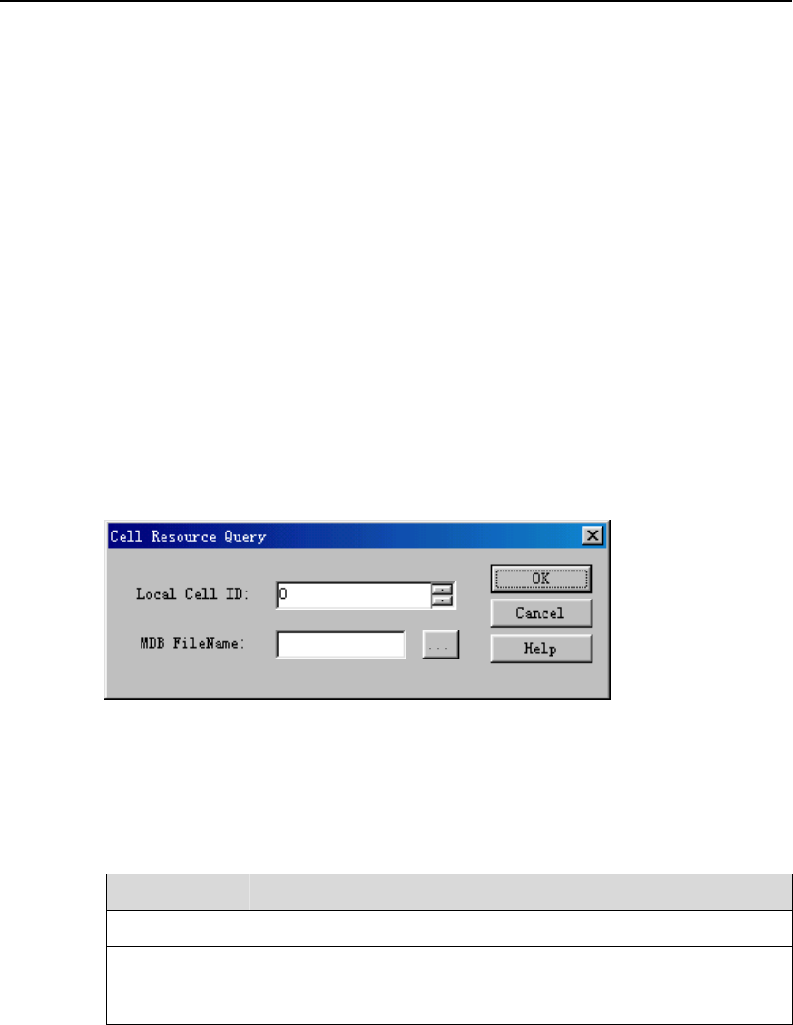
Figure 9-2 Cell Resource Query dialog box
Table 9-2 describes the fields of the Cell Resource Query dialog box.
Table 9-2 Field description of Cell Resource Query dialog box
Field Description
Local Cell ID To set the ID of the local cell
MDB FileName z To create a *.mdb file to save the test curve
z If it is blank, the system saves curve into the default file under
the default directory.
3) Set parameters in the dialog box.
4) Click OK.A monitor window is displayed showing the service resource occupancy
curve.
5) Stop the test in either way below:
z Close the monitor window.

NodeB LMT User Guide
Chapter 9 Monitoring NodeB Performance and State in
Real Time
Huawei Technologies Proprietary
9-5
z Right-click the task in the task list below the graphical area. Click Delete Task on
the shortcut menu to delete the task and curve.
IV. Test Result Analysis
Test result analysis of the querying the cell service resource is as follows:
z Uplink resources: include uplink demodulation resources and uplink decoding
resources. The LMT reports uplink resources in points.
z Downlink resources: include downlink modulation resources and downlink
encoding resources. The LMT reports downlink resources in points.
Note:
The resources for a 12.2 kbit/s voice service channel are regarded as a point. Other
service channel resources can be converted into a multitude of points.
9.5 Testing NodeB RTWP
I. Introduction
The received total wideband power (RTWP) is the received wideband power in the
band of an uplink channel measured at the UTRAN access point. You can calibrate the
gain of uplink RF channels through RTWP measurement.
The NodeB RTWP test has no negative effect on the services.
II. Prerequisite
None.
III. Procedure
Follow the steps below to test the NodeB RTWP:
1) Choose Maintenance Navigator -> Realtime State Monitoring. Right-click on
the RTWP Measurement subnode.
2) Click Create Monitor Task. The system displays the RTWP Measurement dialog
box, as shown in Figure 9-3.
NodeB LMT User Guide
Chapter 9 Monitoring NodeB Performance and State in
Real Time
Huawei Technologies Proprietary
9-6
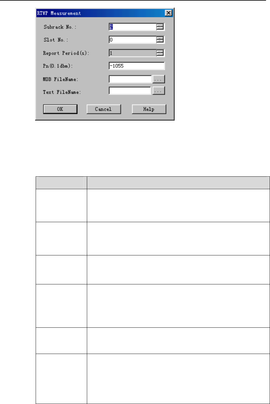
Figure 9-3 RTWP Measurement dialog box
Table 9-3 describes the fields of the RTWP Measurement dialog box.
Table 9-3 Field description of RTWP Measurement dialog box
Field Description
Subrack No. z For the macro NodeB, to set the number of the subrack that
hosts the MTRU with default value 2
z For the DBS3800, to set the number of the subrack that hosts
the MRRU with value range from 20 to 199
Slot No. z For the macro NodeB, to set the number of the slot that hosts
the MTRU with value range from 0 to 5
z For the DBS3800, to set the number of the slot that hosts the
MRRU with default value 0
Report Period(s) z To set intervals of report
z Unit: Second
z Value range: 1 second
Pn(0.1 dBm) z To set the RTWP when the NodeB carries no service, that is,
the initial gain of the uplink channel
z It is the initial reference value to calculate the uplink load of the
cell.
z Default value: –105.5 dBm.
MDB FileName z To create a *.mdb file to save the test curve
z If it is blank, the system saves curve into the default file under
the default directory
Text FileName z To create a *.txt file to save the test data
z If it is blank, the system will not save the data.
z You can open the file to view the data. The file shows the
MTRU/MRRU corresponding to the antennas at the start. In
each line are the GPS time and the RTWP values of a pair of
main and diversity antennas.

NodeB LMT User Guide
Chapter 9 Monitoring NodeB Performance and State in
Real Time
Huawei Technologies Proprietary
9-7
3) Set parameters in the dialog box.
4) Click OK. A monitor window is displayed showing the RTWP curve.
5) Stop the test in either way below:
z Close the monitor window.
z Right-click the task in the task list below the graphical area. Click Delete Task on
the shortcut menu to delete the task and curve.
IV. Test Result Analysis
The analysis of the RTWP test result is as follows:
z If the NodeB is not connected to the antenna and feeder system or a matched load,
the RTWP is about –108 dBm.
z If the NodeB is connected to the antenna and feeder system (with TMA switched
on) or a matched load, the RTWP is about –105 dBm.
z If the servicses are normal and the uplink load reaches 75%, the RTWP is 6 dB
higher than the RTWP when the NodeB does not carry any service.
Note:
z When the RTWP reported is valid, the curve is normal. The vertical axis
corresponds to the reported RTWP with unit of 0.1 dBm.
z When the reported RTWPs are invalid, abnormal RTWP curves are displayed. The
RTWPs for the main antenna form a horizontal line at –1120 dBm on the vertical
axis. The RTWPs for the diversity antenna form a horizontal line at –1115 dBm on
the vertical axis. The error may lie in the absent MTRU/MRRU, a broken link, or a
faulty channel. In this case, you shall clear the fault first.
9.6 Testing NodeB Clock
I. Introduction
The clock source quality is crucial to the operation of the system. You need to handle
the clock alarm in time.
You can test the quality of the clock source beforehand.
The NodeB clock test has no negative effect on the system or services.
II. Prerequisite
A reference clock source to the NodeB must be configured before the clock test.
NodeB LMT User Guide
Chapter 9 Monitoring NodeB Performance and State in
Real Time
Huawei Technologies Proprietary
9-8
III. Procedure
Follow the steps below to perform the clock test:
1) Choose Maintenance Navigator -> Realtime State Monitoring. Right-click on
the Clock Test subnode.
2) Click Create Monitor Task. The system displays the Clock Test dialog box, as
shown in Figure 9-3.
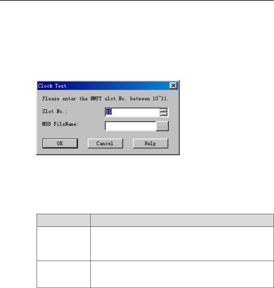
Figure 9-4 Clock Test dialog box
Table 9-4 describes the fields of the Clock Test dialog box.
Table 9-4 Field description of Clock Test dialog box
Field Description
Slot No. z For the macro NodeB, the number of the slot that hosts the
NMPT can be 10 or 11.
z For the DBS3800, the number of the slot that hosts the
MBBU is 0 by default.
MDB FileName z To create a *.mdb file to save the test curve
z If it is blank, the system saves curve into the default file under
the default directory.
3) Set parameters in the dialog box.
4) Click OK. A monitor window is displayed showing the clock test curve.
5) Stop the test in either way below:
z Close the monitor window.
z Right-click the task in the task list below the graphical area. Click Delete Task on
the shortcut menu to delete the task and curve.
IV. Test Result Analysis
Analyses of the NodeB clock test result are as follows:
1) Result reporting period

NodeB LMT User Guide
Chapter 9 Monitoring NodeB Performance and State in
Real Time
Huawei Technologies Proprietary
9-9
The reporting periods of phase discrimination value and DA value are different. The
reporting period of phase discrimination value is 1 second. The reporting period of DA
value depends on the type of the clock source.
z For the GPS or BITS clock source, the reporting period of DA value is 2 minutes in
normal condition. If there is fluctuation or frequency deviation on the clock, the
period may be longer than 2 minutes. It is normal if the first reporting period is
greater than 2 minutes.
z For the Iub clock source, the reporting period of DA value is 30 minutes in normal
situation. If there is fluctuation or frequency deviation on the clock, the period may
be longer than 30 minutes. It is normal if the first reporting period is greater than 30
minutes.
2) Phase discrimination value
If the difference of the reported phase discrimination value and the actual value
(10 MHz) is greater than ±1 Hz, you need to check whether there is problem in the
clock source.
9.7 Scanning NodeB Rx Frequency
I. Introduction
The Rx frequency scanning helps you examine electromagnetic environment and
internal interference of the NodeB.
The process is as follows: The MTRU/MRRU scans the frequency, calculates the
strength of received signals, and then reports the result.
II. Prerequisites
z It is recommended to do Rx frequency scanning before cell configuration.
z The MTRU/MRRU must be blocked before Rx frequency scanning starts.
III. Procedure
Follow the steps below to scan the NodeB Rx frequency:
1) Choose Maintenance Navigator -> Realtime State Monitoring. Right-click on
the Rx Frequency Scanning subnode.
2) Click Create Monitor Task. The system displays the Rx Frequency Scanning
dialog box, as shown in Figure 9-5.
NodeB LMT User Guide
Chapter 9 Monitoring NodeB Performance and State in
Real Time
Huawei Technologies Proprietary
9-10
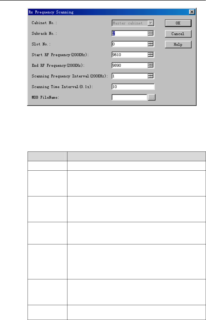
Figure 9-5 Rx Frequency Scanning dialog box
Table 9-5 describes the fields of the Rx Frequency Scanning dialog box.
Table 9-5 Field description of Rx Frequency Scanning dialog box
Field Description
Cabinet No. Value: Master cabinet
Subrack No. z For the macro NodeB, the number of the subrack that hosts
the MTRU is 2.
z For the DBS3800, the number of the subrack that hosts the
MTRU can be any number from 20 to 199.
Slot No. z For the macro NodeB, the number of the slot that hosts the
MTRU is any number from 0 to 5.
z For the DBS3800, the number of the slot that hosts the MTRU
is the default value 0.
Start RF
Frequency
(200kHz)
z To set the start frequency of the scanning
z Value range: 9610 to 9890
z Unit: 200 kHz
End RF
Frequency
(200kHz)
z To set the end frequency of the scanning
z Value range: 9610 to 9890
z Unit: 200 kHz
z Note that the End RF Frequency has to be higher than the
Start RF Frequency.
Scanning
Frequency
Interval
(200kHz)
z To set the frequency intervals of the scanning
z Value range: 1 to 300
z Unit: 200 kHz
Scanning Time
Interval (0.1s)
z Value range: 2 to 600
z Unit: 0.1 s
NodeB LMT User Guide
Chapter 9 Monitoring NodeB Performance and State in
Real Time
Huawei Technologies Proprietary
9-11
Field Description
MDB FileName z To create a *.mdb file to save the test curve
z If it is blank, the system saves curve into the default file under
the default directory.
3) Set parameters in the dialog box.
4) Click OK.
A dialog box prompts you whether to start the Rx frequency scanning.
5) Click Yes.
A monitor window is displayed showing the scanning curve.
Note:
The scanning automatically stops when it reaches the end RF frequency.
6) Stop the test in either way below:
z Close the monitor window.
z Right-click the task in the task list below the graphical area. Click Delete Task on
the shortcut menu to delete the task and curve.
IV. Test Result Analysis
The test result analysis of Rx frequency scanning is as follows:
z If the NodeB is separated from the antenna and feeder system, the curve has
jumps greatly higher than –108 dBm. This indicates that there must be internal
interference of the NodeB.
z If the NodeB is connected to the antenna and feeder system with NTTA powered
on, the curve has jumps greatly higher than –105 dBm. This indicates that there
must be external interference of the NodeB.
z The shape of jumps tells the interference type in most cases:
z A triangular or trapezium jump: There are broadband interferences. The peak of
the jump is the central frequency of the interference.
z A rectangle jump or a jump added with a rectangle: There is individual tone
interference. The central point of the upper side of the rectangle is the interfering
frequency.
9.8 Testing MTRU Output Power
I. Introduction
The MTRU output power test measures the output power of the MTRU, including:
NodeB LMT User Guide
Chapter 9 Monitoring NodeB Performance and State in
Real Time
Huawei Technologies Proprietary
9-12
z Total output power
z Output power of each carrier.
II. Prerequisite
none.
III. Procedure
Follow the steps below to test the MTRU output power:
1) Choose Maintenance Navigator -> Realtime State Monitoring. Right-click on
the MTRU Output Power subnode.
2) Click Create Monitor Task.
The system displays the MTRU Output Power dialog box, as shown in Figure 9-6
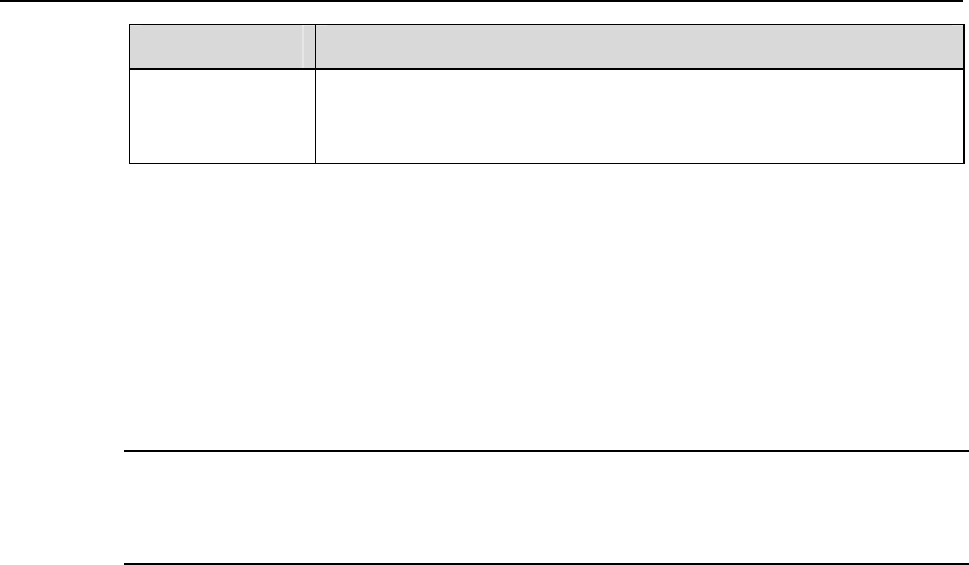
Figure 9-6 MTRU Output Power dialog box
Table 9-6 describes the fields of the MTRU Output Power dialog box.
Table 9-6 Field description of MTRU Output Power dialog box
Field Description
Cabinet No. Value: Master cabinet
Subrack No. z To set the number of the subrack that hosts the MTRU
z Value: 2
Slot No. z To set the number of the slot that hosts MTRU.
z Value range: 0 to 5.
MDB
FileName
z To create a *.mdb file to save the test curve
z If it is blank, the system saves curve into the default file under the
default directory.
3) Set parameters in the dialog box.
NodeB LMT User Guide
Chapter 9 Monitoring NodeB Performance and State in
Real Time
Huawei Technologies Proprietary
9-13
4) Click OK.
A monitor window is displayed showing the service resource occupancy curve.
5) Stop the test in either way below:
z Close the monitor window.
z Right-click the task in the task list below the graphical area. Click Delete Task on
the shortcut menu to delete the task and curve.
IV. Test Result Analysis
Once the test is started, the system reports the output power of the MTRU and each
carrier every two seconds.
9.9 Testing MTRU Temperature
I. Introduction
The MTRU temperature test measures the temperatures of the MTRU board and the
internal power amplifier.
II. Prerequisite
None.
III. Procedure
Follow the steps below to test the MTRU temperature:
1) Choose Maintenance Navigator -> Realtime State Monitoring. Right-click on
the MTRU Temperature subnode.
2) Click Create Monitor Task.
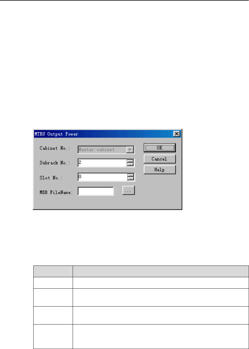
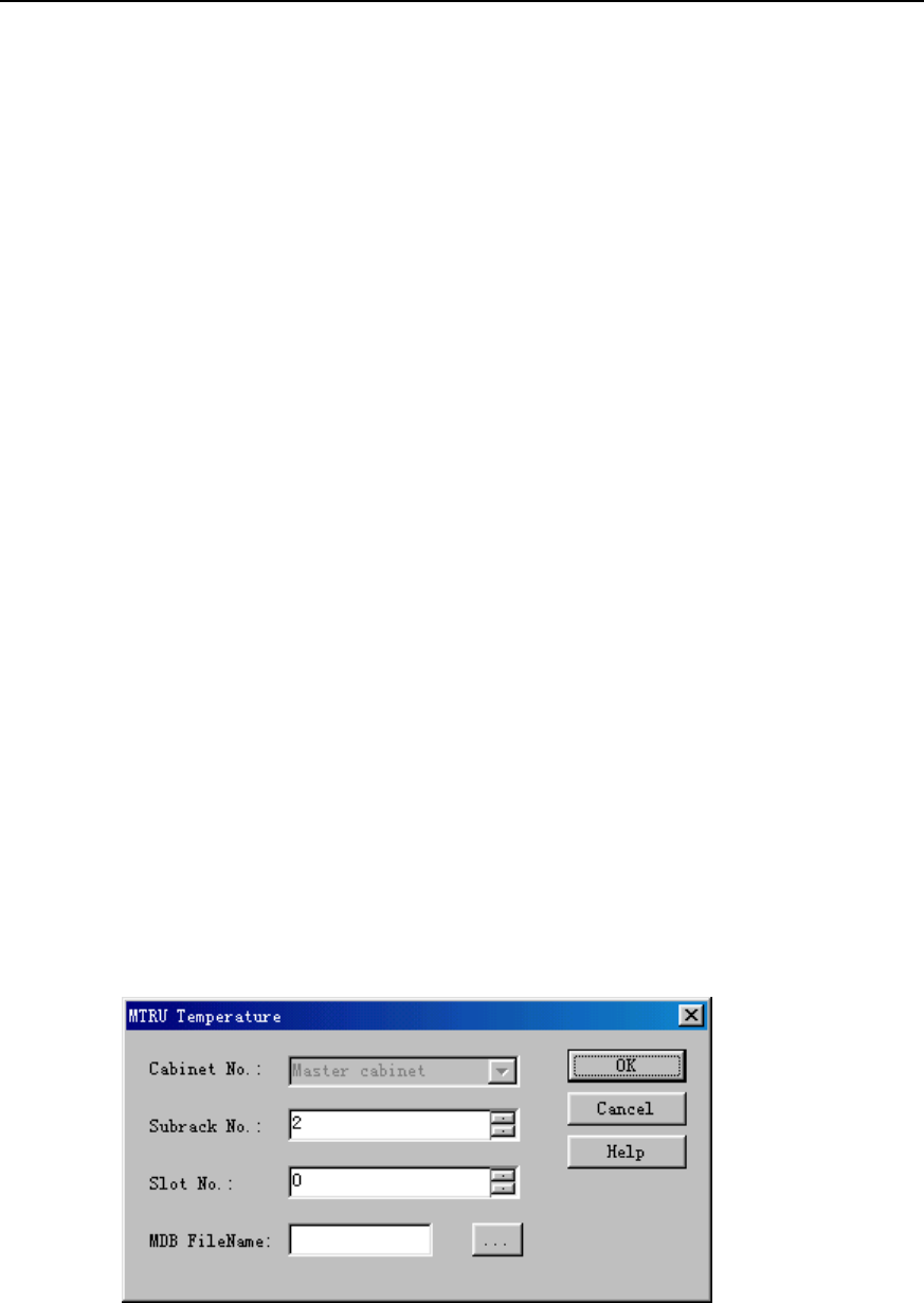
The system displays the MTRU Temperature dialog box, as shown in Figure 9-7.
Figure 9-7 MTRU Temperature dialog box
Table 9-7 describes the fields of the MTRU Temperature dialog box.

NodeB LMT User Guide
Chapter 9 Monitoring NodeB Performance and State in
Real Time
Huawei Technologies Proprietary
9-14
Table 9-7 Field description of MTRU Temperature dialog box
Field Description
Cabinet No. Value: Master cabinet
Subrack No. z To set the number of the subrack that hosts the MTRU
z Value: 2
Slot No. z To set the number of the slot that hosts MTRU.
z Value range: 0 to 5
MDB
FileName
z To create a *.mdb file to save the test curve
z If it is blank, the system saves curve into the default file under
the default directory.
3) Set parameters in the dialog box.
4) Click OK.
A monitor window is displayed showing the MTRU temperature curve.
5) Stop the test in either way below:
z Close the monitor window.
z Right-click the task in the task list below the graphical area. Click Delete Task on
the shortcut menu to delete the task and curve.
IV. Test Result Analysis
z Once the test is started, the system reports the temperatures of the MTRU board
and the internal power amplifier every two seconds.
z Alarms are reported if the temperature of the power amplifier is higher than the
allowed temperature.
9.10 Testing MRRU Output Power
I. Introduction
The MRRU output power test tells the output power status of MRRU, including
z Total output power of MRRU
z Output power of each carrier
II. Prerequisite
None.
III. Procedure
Follow the steps below to test the MRRU output power:
1) Choose Maintenance Navigator -> Realtime State Monitoring. Right-click on
the MRRU Output Power subnode.
NodeB LMT User Guide
Chapter 9 Monitoring NodeB Performance and State in
Real Time
Huawei Technologies Proprietary
9-15
2) Click Create Monitor Task.
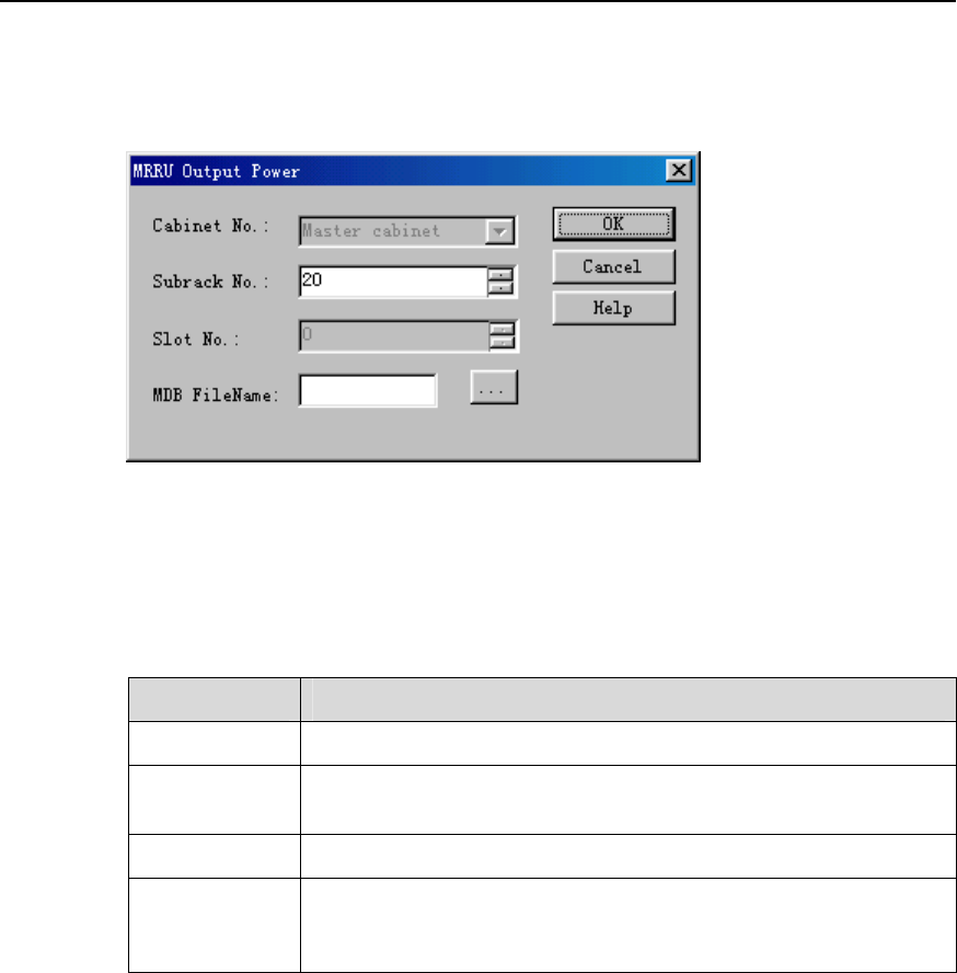
The system displays the MRRU Output Power dialog box, as shown in Figure
9-8.
Figure 9-8 MRRU Output Power dialog box
Table 9-8 describes the fields of the MRRU Output Power dialog box.
Table 9-8 Field description of MRRU Output Power dialog box
Field Description
Cabinet No. Value: Master cabinet
Subrack No. z To set the number of the subrack that hosts the MRRU
z Value range: from 20 to 199
Slot No. Default value: 0
MDB FileName z To create a *.mdb file to save the test curve
z If it is blank, the system saves curve into the default file under
the default directory.
3) Set parameters in the dialog box.
4) Click OK.
A monitor window is displayed showing the curve of the current task.
5) Stop the test in either way below:
z Close the monitor window.
z Right-click the task in the task list below the graphical area. Click Delete Task on
the shortcut menu to delete the task and curve.
IV. Test Result Analysis
Once the test is started, the system reports the output power of the MRRU and each
carrier every two seconds.
NodeB LMT User Guide
Chapter 9 Monitoring NodeB Performance and State in
Real Time
Huawei Technologies Proprietary
9-16
9.11 Testing MRRU Temperature
I. Introduction
The MRRU temperature test tells temperatures of the MRRU and power amplifier in the
MRRU.
II. Prerequisite
None.
III. Procedure
Follow the steps below to test temperatures of the MRRU board and the power
amplifier:
1) Choose Maintenance Navigator -> Realtime State Monitoring. Right-click on
the MRRU Temperature subnode.
2) Click Create Monitor Task.
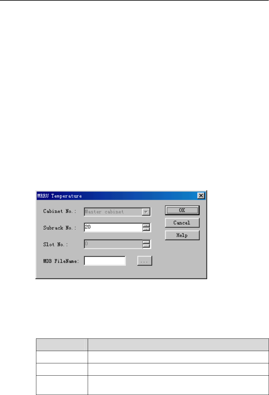
The system displays the MRRU Temperature dialog box, as shown in Figure 9-9.
Figure 9-9 MRRU Temperature dialog box
Table 9-9 describes the fields of the MRRU Temperature dialog box.
Table 9-9 Field description of the MRRU Temperature dialog box
Field Description
Cabinet No. Value: Master cabinet
Subrack No. Value range: 20 to 199
Slot No. z To set the number of the slot that hosts the MRRU
z Default value: 0

NodeB LMT User Guide
Chapter 9 Monitoring NodeB Performance and State in
Real Time
Huawei Technologies Proprietary
9-17
Field Description
MDB FileName z To create a *.mdb file to save the test curve
z If it is blank, the system saves curve into the default file under
the default directory.
3) Set parameters in the dialog box.
4) Click OK.
A monitor window is displayed showing the curve of the current task.
5) Stop the test in either way below:
z Close the monitor window.
z Right-click the task in the task list below the graphical area. Click Delete Task on
the shortcut menu to delete the task and curve.
IV. Test Result Analysis
z Once the test is started, the system reports the temperatures of the MRRU and the
power amplifier in the MRRU every two seconds.
z Alarms are reported when the temperature of the power amplifier is higher than
the allowed temperature.
9.12 Querying Board Service Resource
I. Introduction
The board service resource query shows the use of service resources of the board in
real time. It includes:
z Total service resources of a board
z Service resources in use
z Idle service resources
II. Prerequisite
None.
III. Procedure
Follow the steps below to test the board service resources:
1) Choose Maintenance Navigator -> Realtime State Monitoring. Right-click on
the Board Resource Query subnode.
2) Click Create Monitor Task.
The system displays the Board Resource Query dialog box, as shown in Figure
9-10.
NodeB LMT User Guide
Chapter 9 Monitoring NodeB Performance and State in
Real Time
Huawei Technologies Proprietary
9-18
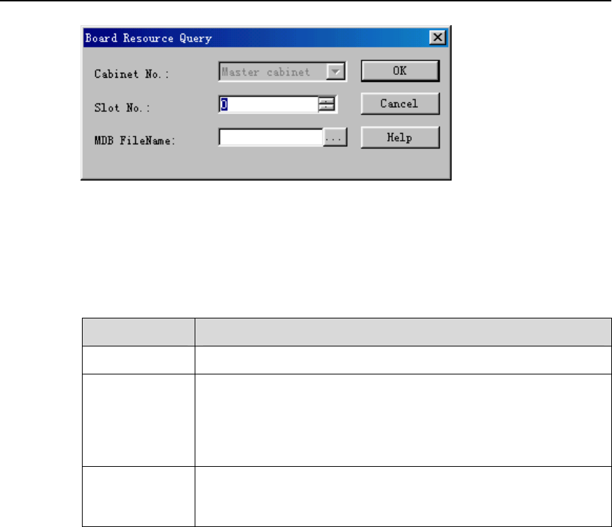
Figure 9-10 Board Resource Query dialog box
Table 9-10 describes the fields of the Board Resource Query dialog box.
Table 9-10 Field description of Board Resource Query dialog box
Field Description
Cabinet No. Value: Master cabinet
Slot No. z For the macro NodeB, to set the numbers of the slots that host
HULP/NDLP, HDLP/NDLP and HBBI with value range from 0
to 9
z For the DBS3800, to set the number of the slot that hosts the
MBBU with default value 0
MDB FileName z To create a *.mdb file to save the test curve
z If it is blank, the system saves curve into the default file under
the default directory.
3) Set parameters in the dialog box.
4) Click OK.
A monitor window is displayed showing the curve of the current task.
5) Stop the test in either way below:
z Close the monitor window.
z Right-click the task in the task list below the graphical area. Click Delete Task on
the shortcut menu to delete the task and curve.
IV. Test Result Analysis
The board service resource occupancy is presented in percentage calculated through
dividing the total points by the occupied points. It includes
z NBBI: resource occupancy for demodulating, decoding and encoding the DSP
z HULP: resource occupancy for demodulating and decoding the DSP
z HDLP: resource occupancy for encoding the DSP

NodeB LMT User Guide
Chapter 9 Monitoring NodeB Performance and State in
Real Time
Huawei Technologies Proprietary
9-19
Note:
z This query is only for the usable DSP. There is no result for the unusable DSP.
z The resources for a 12.2 kbps voice service channel are regarded as a "point".
Other service channel resources can be converted into a multitude of points.
9.13 Routine Testing NodeB E1/T1 Performance
I. Introduction
The E1/T1 performance routine test shows the quality of the E1/T1 cable.
This test has no negative effect on the services, and can be done by the MML
command only.
II. Prerequisite
The E1/T1 cable has no physical damage but has error bit in transmission.
III. Procedure
Follow the steps below to perform an E1/T1 performance routine test:
1) Execute the MML command of STR E1T1RTTST.
An E1/T1 performance routine test is started.
2) Note down the ID for the task under test.
Note:
z When the E1/T1 routine test is started, the NodeB assigns an ID to each task and
sends it to you. With this ID, you can query the task under test.
z If you lose the ID, execute the MML command of LST RTTST to get it.
3) Wait for a while longer than the test time set by the MML command of STR
E1T1RTTST. Execute the MML command of STP RTTST to stop the test.
Then the system displays the E1/T1 performance routine test result.
IV. Test Result Analysis
You can tell the E1/T1 link status through E1/T1 performance routine test in real time.
Any error in the test results indicates a line fault.

NodeB LMT User Guide
Chapter 9 Monitoring NodeB Performance and State in
Real Time
Huawei Technologies Proprietary
9-20
The test result is invalid when there is signal loss or out-of-synchronization frame. In
this case, all the indices should be 0.
The indices in the E1/T1 performance routine test results include
z Line Conflicting Error Rate: measures conflicts in line code type.
z Framing Error Rate: measures errors in frame synchronization signals.
z CRC Error Rate: measures errors in CRC4 multi-frame receiving.
z Ebit Error Rate: measures errors in CRC4 multi-frame transmitting at the peer
end.
The above indices reflect the transmission status of the E1/T1 link, which is related to
the code and frame structure of the link.
z If an error occurs, check that the code types and frame structures at both ends of
the link are the same.
z If they are the same but the error still exists, check the clock status. This is
because of vibrations of the clock.
9.14 Routine Testing STM-1 Performance
I. Introduction
The STM-1 performance routine test shows the STM-1 link status.
This routine test has no negative impact on the services and can be done by the MML
command only.
II. Prerequisite
The STM-1 link has no physical damage but has error bit in transmission.
III. Procedure
Follow the steps below to perform the STM-1 performance routine test:
1) Execute the MML command of STR STM1RTTST.
An STM-1 performance routine test is started.
2) Note down the ID for the task under test.
Note:
z When the STM-1 performance routine test is started, the NodeB assigns an ID to
each task and sends it to you. With this ID, you can query the task under test.
z If you lose the ID, execute the MML command of LST RTTST to get it.

NodeB LMT User Guide
Chapter 9 Monitoring NodeB Performance and State in
Real Time
Huawei Technologies Proprietary
9-21
3) Wait for a while longer than the test time set by the MML command of STR
STM1RTTST. Execute the MML command of STP RTTST to stop the test.
Then the system displays the results of the STM-1 performance routine test.
IV. Test Result Analysis
You can tell the STM-1 link status by the STM-1 performance routine test in real time.
Any error in the test results indicates a line fault.
The test result is invalid when there is signal loss or out-of-synchronization frame. In
this case, all the indices should be 0.
The indices in the STM-1 performance routine test results include
z LOCD Event Rate: measures lost cells.
z Rx Corrected HEC Error Rate: measures HEC errors because of single-bit errors
during cell delimitation.
z Rx Uncorrectable HEC Error Rate: measures HEC errors because of multi-bit
errors during cell delimitation.
z Off Event Rate: measures errors in SDH frame synchronization.
z Line BIP Error Rate: measures line bit errors.
z Section BIP Error Rate: measures section bit errors.
z Path BIP Error Rate: measures path bit errors.
z Line FEBE Error Rate: measures bit errors in receiving on the line.
z Path FEBE Error Rate: measures bit errors in receiving on the path.
z Idle Cell Rate: measures wrongly inserted cells.
z Tx Cell Rate: measures cells sent over the UTOPIA port.
z Rx Cell Rate: measures cells received over the UTOPIA port.
The above indices reflects the receive status of the STM-1 link. STM-1 link status
depends on the cable clock and the physical status of the link. If there is any error,
query the alarm and line clock status.

NodeB LMT User Guide Table of Contents
Table of Contents
Chapter 10 Monitoring External Environment of NodeB......................................................... 10-1
10.1 About This Chapter........................................................................................................ 10-1
10.2 Monitoring External Environment of NodeB .................................................................. 10-1
10.2.1 Overview of External Environment...................................................................... 10-1
10.2.2 Monitoring Input Power Supply ........................................................................... 10-1
10.2.3 Monitoring Temperature and Humidity................................................................ 10-2
10.2.4 Smoke and Anti-theft Alarms .............................................................................. 10-3
10.2.5 Customized Alarms ............................................................................................. 10-3
10.3 Monitoring Input Power Supply...................................................................................... 10-4
10.3.1 Overview ............................................................................................................. 10-4
10.3.2 Setting NEMU Input Voltage Alarm Thresholds.................................................. 10-4
10.3.3 Querying NEMU Alarm Thresholds for Input Voltage ......................................... 10-4
10.3.4 Querying NEMU Input Voltage............................................................................ 10-4
10.4 Monitoring Temperature and Humidity .......................................................................... 10-5
10.4.1 Overview ............................................................................................................. 10-5
10.4.2 Querying NEMU Temperature and Humidity ...................................................... 10-5
10.4.3 Setting Thresholds of NEMU Temperature and Humidity................................... 10-5
10.4.4 Querying Thresholds of NEMU Temperature and Humidity ............................... 10-6
10.5 Smoke and Anti-theft Alarms......................................................................................... 10-6
10.5.1 Overview ............................................................................................................. 10-6
10.5.2 Clearing NEMU Smoke and Enclosure Alarms................................................... 10-6
Huawei Technologies Proprietary
i

NodeB LMT User Guide Chapter 10 Monitoring External Environment of NodeB
Chapter 10 Monitoring External Environment of
NodeB
10.1 About This Chapter
This chapter describes how to monitor the external environment of the NodeB through
the LMT.
10.2 Monitoring External Environment of NodeB
10.2.1 Overview of External Environment
To ensure long-term stable running of the NodeB, you need to monitor the environment
of the NodeB equipment room. It includes:
z Monitoring Input Power Supply
z Monitoring Temperature and Humidity
z Smoke and Anti-theft Alarms
z Customized Alarms
10.2.2 Monitoring Input Power Supply
I. DC Power Supply
The NodeB uses –48 V DC power supply which shall meet the following requirements:
z Allowed voltage fluctuation range: –40 V to +60 V DC
z Regulated voltage precision: when the AC input voltage fluctuates between 85%
and 110% of the rated value and the load current fluctuates between 5% and
100% of the rated value, the output voltage of the rectifier stays at a value in the
range between –46.0 V and –56.4 V. The regulated voltage precision is smaller
or equal to 1%.
z Overshoot range of powering on or off NodeB: within the range of ±5% of the rated
DC output voltage
z Peak to peak noise voltage: smaller or equal to 200 mV
z Dynamic response: The restore time is shorter than 200 ms. The overshoot value
is within the range of –5% to +5% of the rectified DC output voltage.
Huawei Technologies Proprietary
10-1

NodeB LMT User Guide Chapter 10 Monitoring External Environment of NodeB
II. AC Output Power Supply
The AC power supply for the NodeB shall meet the following requirements:
z The electric network for the NodeB is independently and good in quality.
z The AC power distribution capacity of the equipment room depends on the
working current and fault current of the equipment. Each independent device must
be equipped with independent facilities for AC power distribution protection. The
threshold of the protection switch shall be higher than the downstream electric
equipment.
z Use voltage regulation devices in either case below:
z When the communications equipment is directly powered by mains supply, the
power supply voltage is 5% higher or 10% lower than the rated voltage or out of
the allowed voltage range of the communications equipment.
z When the communications equipment is not directly powered by mains supply, the
power supply voltage is 10% higher or 15% lower than the rated voltage or out of
the allowed AC input voltage range of the DC power equipment.
z Apply the UPS or DC-to-AC converters to the power supply for normal services.
z To ensure critical communications load and power load in mains failure, the office
site shall be equipped with a generator set for power supply. The capability of the
set is 1.5 to 2 times of the total capability of AC uninterruptible electric equipment.
z The AC voltage and its fluctuation range shall meet the requirements listed in
Table 10-1.
Table 10-1 Requirements for AC voltage and its fluctuation range
Input voltage range Power frequency Wave distortion
90% to 110% of rated
voltage
98% to 102% of rated
power frequency
Smaller than the total
harmonic component
10.2.3 Monitoring Temperature and Humidity
Table 10-2 lists the requirements for the temperature and humidity of the equipment
room.
Table 10-2 NodeB working conditions
Item Range
Temperature 0°C to 45°C Normal operating
conditions Relative humidity 20% RH to 85% RH
Temperature –5°C to +50°C
Safe operating conditions
Relative humidity 5% RH to 95% RH
Huawei Technologies Proprietary
10-2

NodeB LMT User Guide Chapter 10 Monitoring External Environment of NodeB
Note:
z In normal operating conditions, measure the temperature and humidity 2 meters
above the floor and 0.4 meter in front of the equipment. Make sure that there are no
fenders in front of or behind the rack during the process.
z Safe operating condition means the system operates for less than 48 hours
continuously at a time and less than 360 hours in sum in a year.
10.2.4 Smoke and Anti-theft Alarms
z Smoke alarm: monitors smoke and fire in the NodeB site in real time.
z Anti-theft alarm: monitors the equipment room in case of theft. It is recommended
to use dual-mode detector with infrared and short wave.
10.2.5 Customized Alarms
Customized alarms refer to alarms customized by you.
Elements for customizing an alarm include:
z External interface of the NodeB
z Alarming ID corresponding to the external interface
z Test mode for the external interface, such as high electric level, low electric level
z Whether to close the customized alarm of the external interface
The value range for the customized alarm is from 65334 to 65534.
Note:
z The NodeB does not support modification on the customized alarm severity.
z The alarm name, alarm ID and alarm severity are defined in the M2000 server. For
details, see iManager M2000 Mobile Element Management System Operation
Manual.
Huawei Technologies Proprietary
10-3

NodeB LMT User Guide Chapter 10 Monitoring External Environment of NodeB
10.3 Monitoring Input Power Supply
10.3.1 Overview
The input power monitoring refers to monitoring the input power in real time. Once the
input voltage does not conform to the threshold settings, the system reports an alarm.
10.3.2 Setting NEMU Input Voltage Alarm Thresholds
I. Introduction
You can set the alarm thresholds for the NEMU input voltage.
II. Procedure
Execute the MML command of SET NEMUINVLIMIT.
10.3.3 Querying NEMU Alarm Thresholds for Input Voltage
I. Introduction
You can query the alarm thresholds for NEMU input voltage.
II. Procedure
Execute the MML command of LST NEMUINVLIMIT.
10.3.4 Querying NEMU Input Voltage
I. Introduction
You can query the NEMU input voltage.
II. Procedure
Execute the MML command of DSP NEMUINV.
Huawei Technologies Proprietary
10-4

NodeB LMT User Guide Chapter 10 Monitoring External Environment of NodeB
10.4 Monitoring Temperature and Humidity
10.4.1 Overview
Monitoring the temperature and humidity refers to monitoring the temperature and
humidity of the NodeB external environment in real time. Once the input power does
not conform to the thresholds, the system reports an alarm.
10.4.2 Querying NEMU Temperature and Humidity
I. Introduction
You can monitor the cabinet ambient temperature and humidity by querying the NEMU
temperature and humidity.
II. Procedure
Execute the MML command of DSP NEMUTH.
10.4.3 Setting Thresholds of NEMU Temperature and Humidity
I. Introduction
You can set the thresholds of the ambient temperature and humidity of the NEMU.
The NEMU measures the ambient temperature and humidity of the equipment room
through the temperature and humidity sensors, and compares the measured values
with the preset thresholds. If the values do not conform to the thresholds, the NEMU
generates corresponding temperature and humidity alarms.
II. Procedure
Caution:
z Execute the command only when the NEMU works well.
z There must be a gap of no less than 3°C between the upper limit and the lower limit
of the temperature, and a gap of no less than 5% between those of the humidity.
Execute the MML command of MOD NEMUTHLIMIT.
Huawei Technologies Proprietary
10-5

NodeB LMT User Guide Chapter 10 Monitoring External Environment of NodeB
10.4.4 Querying Thresholds of NEMU Temperature and Humidity
I. Introduction
You can query the thresholds of the ambient temperature and humidity of the NEMU.
II. Procedure
Caution:
Execute the command only when the NEMU works well.
Execute the MML command of LST NEMUTHLIMIT.
10.5 Smoke and Anti-theft Alarms
10.5.1 Overview
You can monitor whether there is smoke, fire or theft in the equipment room in real time
with the smoke and anti-theft alarms.
10.5.2 Clearing NEMU Smoke and Enclosure Alarms
I. Introduction
You can clear the NEMU smoke and enclosure alarms.
II. Procedure
Execute the MML command of CLR NEMUALM.
Huawei Technologies Proprietary
10-6

NodeB LMT User Guide Table of Contents
Table of Contents
Chapter 11 141 Test..................................................................................................................... 11-1
11.1 About This Chapter........................................................................................................ 11-1
11.2 Overview ........................................................................................................................ 11-1
11.2.1 Introduction to 141 Test ...................................................................................... 11-1
11.2.2 Precautions ......................................................................................................... 11-1
11.3 Setting Cell Parameters................................................................................................. 11-2
11.4 UL 141 Test ................................................................................................................... 11-9
11.4.1 Introduction to UL 141 Test................................................................................. 11-9
11.4.2 Testing UL DPCH.............................................................................................. 11-10
11.4.3 Testing UL RACH.............................................................................................. 11-14
11.5 DL 141 Test ................................................................................................................. 11-17
11.5.1 Introduction to DL 141 Test............................................................................... 11-17
11.5.2 Testing Max Transmit Power ............................................................................ 11-18
11.5.3 Testing CPICH Power Accuracy ....................................................................... 11-20
11.5.4 Testing Frequency Error ................................................................................... 11-21
11.5.5 Testing Transmit Intermodulation...................................................................... 11-23
11.5.6 Testing IPDL Time Mask................................................................................... 11-24
11.5.7 Testing Power Control Steps ............................................................................ 11-25
11.5.8 Testing Power Control Step or Dynamic Range ............................................... 11-28
11.5.9 Testing Total Dynamic Range........................................................................... 11-30
11.5.10 Testing Occupied Bandwidth .......................................................................... 11-31
11.5.11 Testing Spurious Emission.............................................................................. 11-32
11.5.12 Testing Spectrum Emission ............................................................................ 11-35
11.5.13 Testing ACLR.................................................................................................. 11-36
11.5.14 Testing EVM.................................................................................................... 11-37
11.5.15 Testing PCDE.................................................................................................. 11-38
Huawei Technologies Proprietary
i

NodeB LMT User Guide Chapter 11 141 Test
Chapter 11 141 Test
11.1 About This Chapter
This chapter describes how to test the NodeB RF performance through the LMT,
including
z Overview
z Setting Cell Parameters
z UL 141 Test
z DL 141 Test
11.2 Overview
11.2.1 Introduction to 141 Test
The 141 test is based on the 3GPP TS25.141 protocol, which tests the NodeB RF
performance.
The 141 test mainly depends on the self-test of the equipment. This means the
functional test and index test of the equipment are completed by the built-in test
modules such as the software module and hardware module.
The 141 test needs external devices to set up a test environment before the NodeB
carries services. The 141 test applies to preliminary RF performance acceptance in the
initial phase of NodeB.
The 141 test on the NodeB include
z UL 141 Test
z DL 141 Test
11.2.2 Precautions
Be cautious about the following items before a 141 test:
z External devices are required for the test because it cannot be done on the NodeB
alone.
Huawei Technologies Proprietary
11-1

NodeB LMT User Guide Chapter 11 141 Test
Note:
For details of setting up compatible test environment and operating other devices, see
relevant RF test guides.
z You need to disconnect the NodeB with the RNC before the 141 test. In that case
the NodeB cannot carry services. Try to avoid this test on a running NodeB.
z It is recommended to finish this test before the NodeB starts to carry services.
z To ensure normal services on the NodeB, reset the NodeB after the 141 test.
You can get the 141 test result as shown on the 141 test tab page in the output area.
11.3 Setting Cell Parameters
I. Introduction
Before a 141 test, select the cell to be tested and then the test item.
The system sets up a channel according to the test item and other specified parameters.
You need to set part of the parameters manually.
II. Prerequisite
None.
III. Procedure
To set the cell parameters, proceed as follows:
1) Choose Maintenance Navigator -> Test Management. Then double-click the
141 Test subnode.
A dialog box opens up for your confirmation.
2) Click OK.
The system displays the 141 Test dialog box as shown in Figure 11-1.
Huawei Technologies Proprietary
11-2
NodeB LMT User Guide Chapter 11 141 Test
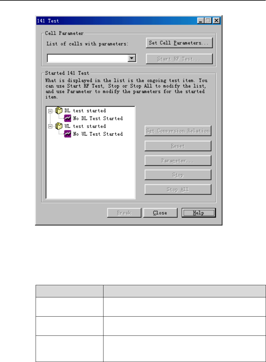
Figure 11-1 141 Test dialog box
Table 11-1 describes the fields of the 141 Test dialog box.
Table 11-1 Field description of 141 Test dialog box
Field Description
List of cells with
parameters To list the cells set with parameters.
Set Cell Parameters… By clicking this button, you can set the parameters of a cell
or modify the preset parameters for a cell.
Start RF Test…
This button is applicable only when cell parameters have
been set. By clicking this button you can start an RF 141
test.
Huawei Technologies Proprietary
11-3

NodeB LMT User Guide Chapter 11 141 Test
Field Description
Started 141 Test
There are two nodes in this pane:
z DL test started
z UL test started
The subnodes respectively display the started UL and DL
test items.
The information in this pane is automatically refreshed.
Set Conversion
Relation
The TPC commands in the UL need to be transferred to
the DL in test of power control steps of the DL 141 test.
Therefore, you need to set relations between the UL
channel and the DL channel before the test.
By clicking this button, you can set relations between the
UL and the DL channels before starting the test of power
control steps.
Reset By clicking this button, you can reset the reported
information during the UL 141 test.
Parameter
By choosing an item under test and clicking this button,
you can query parameters of that item.
It is only available in modifying some parameters for the
total dynamic range test in the DL 141 test. For other tests,
you can only query other than modify the parameters by
clicking this button.
Stop By choosing an item under test and clicking this button,
you can stop that item.
Stop All By clicking this button, you can stop all the test items under
test.
Close By clicking this button, you can close the dialog box.
3) Click Set Cell Parameters in the dialog box. The system displays Cell
Parameters dialog box as shown in Figure 11-2.
Huawei Technologies Proprietary
11-4
NodeB LMT User Guide Chapter 11 141 Test
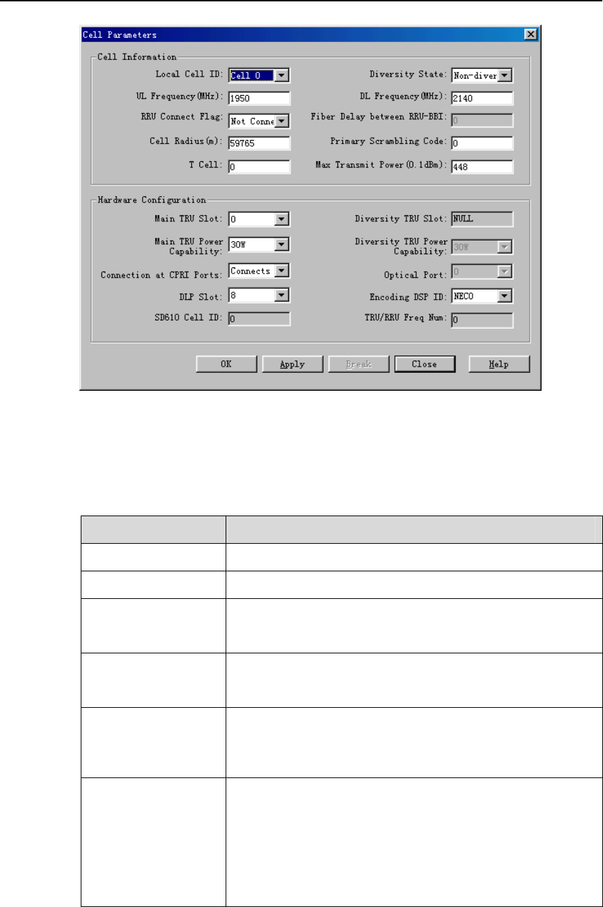
Figure 11-2 Cell Parameters dialog box (macro NodeB)
Table 11-2 describes the fields of the Cell Parameters dialog box of the macro NodeB.
Table 11-2 Field description of Cell Parameters dialog box
Field Description
Local Cell ID Value range: Cell 0 to Cell 11
Diversity State Value range: Non-diversity, Diversity
UL Frequency (MHz)
Value range: 400.0 to 2500.0
Unit: MHz
DL Frequency (MHz)
Value range: 400.0 to 2500.0
Unit: MHz
RRU Connect Flag
whether the RRU is connected or not
Be sure to select Connected with RRU when an RRU is
configured.
Fiber Delay between
RRU-BBI
The delay caused by optical fibers between the BBI and the
RRU
When the space between the BBI and the RRU is greater
than three meters, connect them through optical fibers.
When you select RRU Connect Flag -> Not Connected
with RRU, the value is unavailable.
Huawei Technologies Proprietary
11-5

NodeB LMT User Guide Chapter 11 141 Test
Field Description
Cell Radius (m)
Value range: 150 to 180000
Unit: meter
Primary Scrambling
Code
Value range: 0 to 511
Default value: 0
Unit: Chip
T Cell
Value range: 0 to 9
Default value: 0
Unit: 256Chip
Max Transmit Power
(0.1dbm)
Value range: 0 to 50 dBm
Precision: 0.1 dBm
Main TRU Slot
To set the Tx main channel for the cell
z When you select Diversity State -> Diversity, the value
of the Tx main channel for that cell is 0, 2, 4.
z When you select Diversity State -> Non-diversity, the
value of the Tx channel for that cell is 0, 1, 2, 3, 4, 5.
Diversity TRU Slot
To set the Tx diversity channel for the cell
z When you select Diversity State -> Diversity, it will be
dimmed as 1.
z When you select Diversity State -> Non-diversity, it will
be dimmed as NULL.
Main TRU Power
Capability
The PA specification in the main MTRU
The value must be consistent with the MTRU type.
Value range: 30 W, 40 W.
Diversity TRU Power
Capability
It refers to the PA specification in the diversity MTRU.
z When you select Diversity State -> Diversity, the value
is either 30 W or 40 W, which is decided by the MTRU
type.
z When you select Diversity State -> Non-diversity, the
value is not available.
Connection at CPRI
Ports
The connection between the MTRU and HBBI
Value range: Connects to NBBI0 only, Connects to NBBI1
only, Connects to both NBBI0 and NBBI1
Optical Port Unavailable value: 0
DLP Slot
To set the number of the slot that hosts the HDLP/NDLP and
HBBI which contain encoding DSPs
Value range: 0, 1, 8, 9
0 and 1 indicate the HBBI while 8 and 9 indicate the
HDLP/NDLP.
Huawei Technologies Proprietary
11-6
NodeB LMT User Guide Chapter 11 141 Test
Field Description
Encoding DSP ID
One HDLP/NDLP contains three encoding DSPs. One HBBI
Contains one encoding DSP.
Each encoding DSP supports up to two cells.
z When you set the DLP Slot as 0 or 1, the value can be
NEC0 only.
z When you set the DLP Slot as 8 or 9, the value can be
NEC0, NEC1 or NEC2.
SD610 Cell ID Unavailable value: 0
TRU/RRU Freq Num Unavailable value: 0
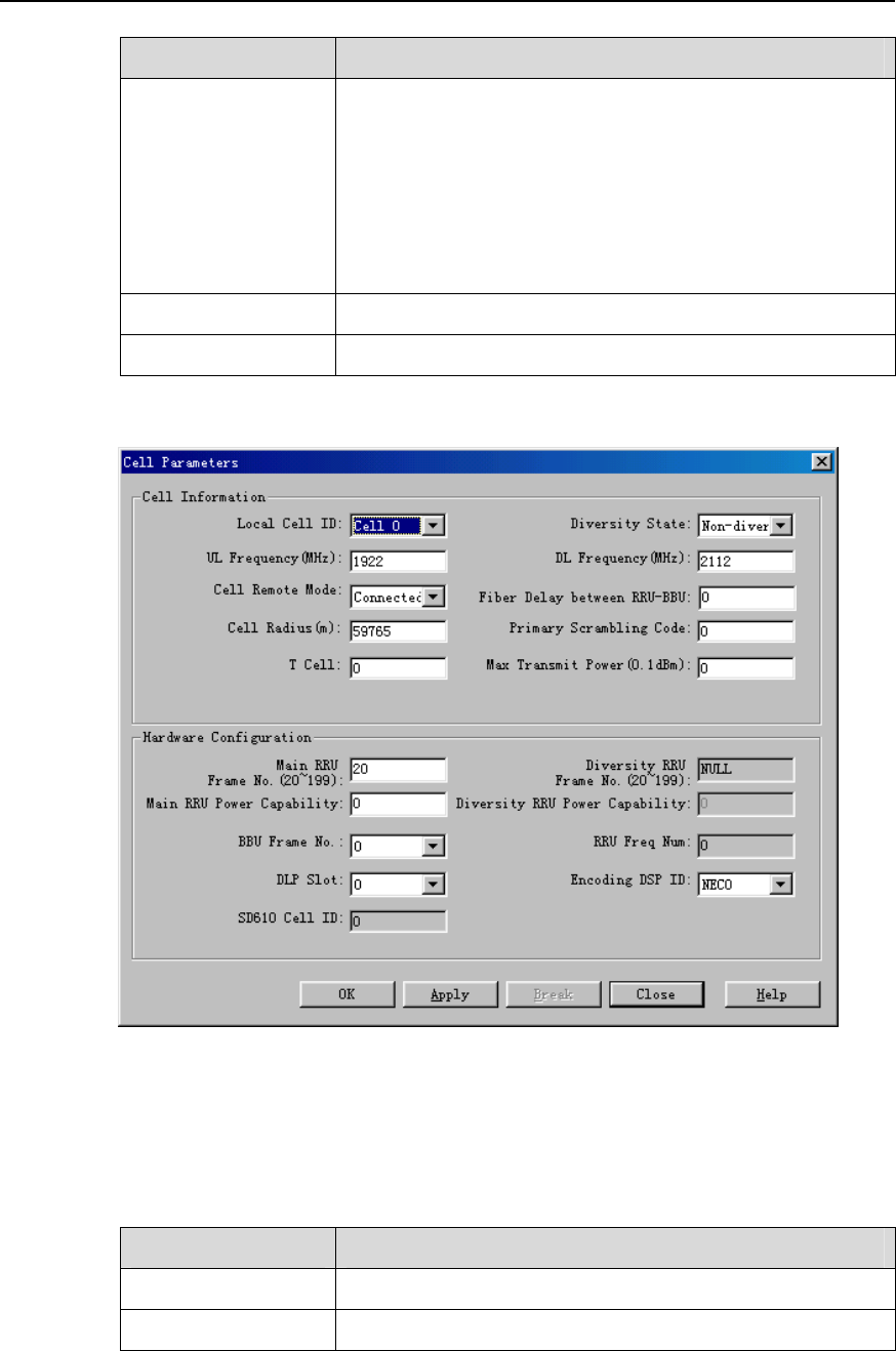
Figure 11-3 Cell Parameters dialog box (DBS3800)
Table 11-3 describes the fields of the Cell Parameters dialog box of the DBS3800.
Table 11-3 Cell Parameters dialog box of DBS3800
Field Description
Local Cell ID Value range: Cell 0 to Cell 2
Diversity State Value range: Diversity, Non-diversity
Huawei Technologies Proprietary
11-7

NodeB LMT User Guide Chapter 11 141 Test
Field Description
UL Frequency (MHz)
Value range: 400.0 to 2500.0
Unit: MHz
DL Frequency (MHz)
Value range: 400.0 to 2500.0
Unit: MHz
Cell Remote Mode
To decide whether to use the remote mode
Be sure to select Connected with RRU when an RRU is
configured.
Fiber Delay between
RRU-BBU
It refers to the delay caused by optical fibers between the
BBU and RRU. When the space between the BBU the RRU
is greater than three meters, connect them through optical
fibers.
Cell Radius (m)
Value range: 150 to 180000
Unit: MHz
Primary Scrambling
Code
Value range: 0 to 511
Default value: 0
Unit: Chip
T Cell
Value range: 0 to 9
Default value: 0
Unit: 256Chip
Max Transmit Power
(0.1 dBm)
Value range: 0 to 50.0 dBm
Precision: 0.1 dBm
Main RRU Frame
No. (20~199) Value range: 20 to 199
Diversity RRU Frame
No. (20~199)
z When you select Diversity State -> Diversity, the
default value is 21.
z When you select Diversity State -> Non-diversity, the
value is dimmed as NULL.
Main RRU Power
Capability
It refers to the PA specifications in the main RRU. The value
must be consistent with the RRU type.
Diversity RRU Power
Capability
It refers to the PA specifications in the diversity RRU.
z When you select Diversity State -> Diversity, the value
must be consistent with the RRU type.
z When you select Diversity State -> Non-diversity, the
value is unavailable as 0.
BBU Frame No. Default value: 0
RRU Freq Num Unavailable value: 0.
DLP Slot Default value: 0
Huawei Technologies Proprietary
11-8

NodeB LMT User Guide Chapter 11 141 Test
Field Description
Encoding DSP ID Default value: NEC0
SD610 Cell ID Unavailable value: 0.
4) Set the parameters for the cell to be tested in the dialog box.
5) Click OK and return to the 141 Test dialog box.
Then the Start RF Test… button becomes available.
11.4 UL 141 Test
11.4.1 Introduction to UL 141 Test
The UL 141 test is to test the RF performance of the NodeB Rx channels. During the
test, the NodeB sets up UL channels between the boards of MTRU, HBBI and HULP
(NULP).
According to different UL channels, the UL 141 test is divided into
z UL DPCH 141 test
z UL RACH 141 test
z UL HS-DPCCH 141 test
The test process is as follows:
1) Use a signal generator to transmit signals for the UL 141 test. For any type of 141
test, the NodeB only receives and displays the measured BER/BLER values on
the LMT interface.
2) Adjust the transmitted signals until the BER/BLER values meet the RF
performance requirements.
3) Record the data measured.
Then you get the test result. You can verify the result with the 3GPP TS25.141 protocol.
The UL 141 test items include
z Reference receive sensitivity
z Dynamic range of received signals
z Adjacent channel selectivity
z Blocking feature
z Intermodulation feature
z Rx spurious emissions
z Internal BER/BLER verification
During the test, select different test items for different NodeB RF performance. For
details, see the 3GPP TS25.141 protocol.
Huawei Technologies Proprietary
11-9

NodeB LMT User Guide Chapter 11 141 Test
11.4.2 Testing UL DPCH
I. Introduction to UL DPCH Test
Before a UL DPCH test, the NodeB runs as follows:
1) Decide whether the test mode is Diversity Test, Main Test or Main/Diversity on the
MTRU/MRRU.
2) Close the channels not in use.
3) Establish channels between UL processing units according to preset parameters.
4) Start the UL DPCH test.
II. Prerequisite
You have set the cell parameters related to this test.
III. Procedure
Follow the steps below to test the UL DPCH:
1) Choose Maintenance Navigator -> Test Management. Then double-click the
141 Test subnode.
A dialog box opens up for your confirmation.
2) Click OK.
The system displays the 141 Test dialog box as shown in Figure 11-1.
Huawei Technologies Proprietary
11-10
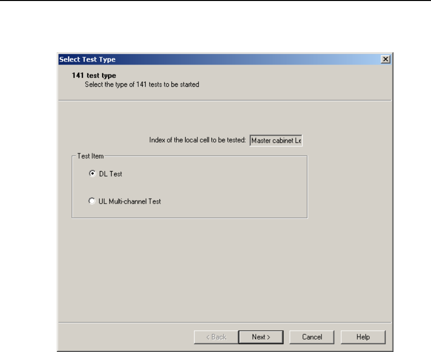
NodeB LMT User Guide Chapter 11 141 Test
Click Start RF Test….
The 141 test type dialog box opens up as shown in Figure 11-4.
Figure 11-4 141 test type dialog box
3) Choose UL Multi-channel Test in the dialog box.
4) Click Next.
The UL Test Item dialog box opens up as shown in Figure 11-5.
Huawei Technologies Proprietary
11-11
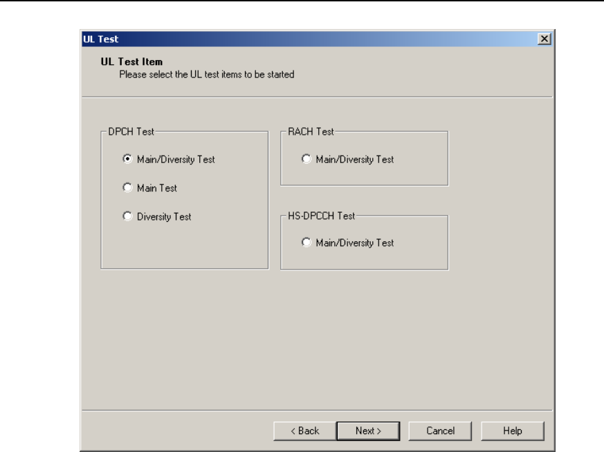
NodeB LMT User Guide Chapter 11 141 Test
Figure 11-5 UL Test Item dialog box
5) Choose Main/Diversity Test, Main Test or Diversity Test under DPCH Test in
the dialog box.
Huawei Technologies Proprietary
11-12
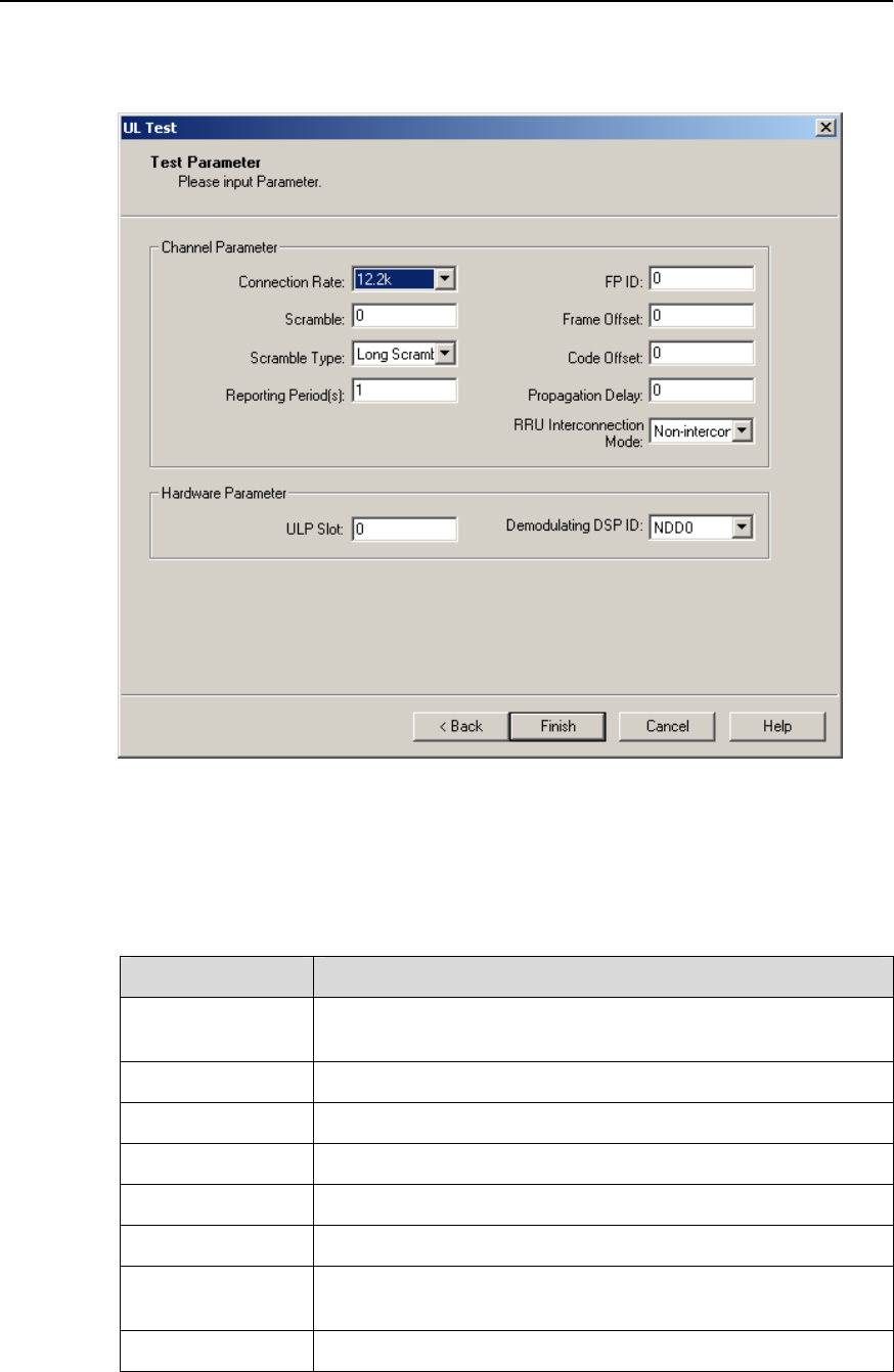
NodeB LMT User Guide Chapter 11 141 Test
Click Next.
The Test Parameter dialog box opens up as shown in Figure 11-6.
Figure 11-6 Test Parameters dialog box (UL DPCH 141 test)
Table 11-4 describes the fields of the Test Parameter dialog box (UL DPCH test).
Table 11-4 Field description of Test Parameter dialog box (UL DPCH test)
Field Description
Connection Rate
z To set the service bit rate of the channel
z Value range: 12.2 kbit/s, 64 kbit/s, 144 kbit/s, 384 kbit/s
FP ID Value range: 0 to 499
Scramble Value range: 0 to 16777215
Frame Offset Value range: 0 to 255
Scramble Type Value range: Long Scramble, Short Scramble
Code Offset Value range: 0 to 38399
Reporting
Period(s)
z To set the reporting period of test result
z Value range: 1 to 255
Propagation Delay Value range: 0 to 255
Huawei Technologies Proprietary
11-13

NodeB LMT User Guide Chapter 11 141 Test
Field Description
RRU
Interconnection
Mode
Value range: Non-interconnection Mode, Interconnection
Mode
ULP Slot
z To set the number of the slot that hosts the HULP (and/or
NULP) and HBBI which contain demodulating DSPs.
z Value range: 0 to 7
z 0 and 1 indicate the HBBI while 2 to 7 indicate the HULP
(and/or NULP).
Demodulating
DSP ID
z One HULP (and/or NULP) has two demodulating DSPs.
One HBBI has one demodulating DSP.
z When you set the ULP Slot as 0 or 1, this value can be
Demodulating NDD0 only.
z When you set the ULP Slot as any number from 2 to 7, this
value can be Demodulating NDD0 or Demodulating
NDD1.
6) Set the parameters in the dialog box.
7) Click Finish.
A UL DPCH test is started. You are presented with the 141 Test dialog box. A
DPCH Test subnode is added under the UL test started node at the same time.
8) Adjust the transmitted signals until the BER/BLER values displayed on Test
Output meet the NodeB RF performance requirements.
9) Record the test results.
10) Select the DPCH Test subnode under UL test started. Then click Stop.
The test is stopped and the DPCH Test subnode is deleted.
IV. Analysis of UL DPCH Test Results
Compare the test results under different test environments with technical specifications
in the 3GPP TS25.141 protocol. If the results comply with the technical specifications,
the system passes the UL DPCH test.
11.4.3 Testing UL RACH
I. Introduction to UL RACH 141 Test
Before a UL RACH test, the NodeB runs as follows:
1) Choose the test mode of Main/Diversity Test on the MTRU/MRRU.
2) Establish channels on UL processing units according to preset parameters.
3) Start the UL RACH test.
Huawei Technologies Proprietary
11-14
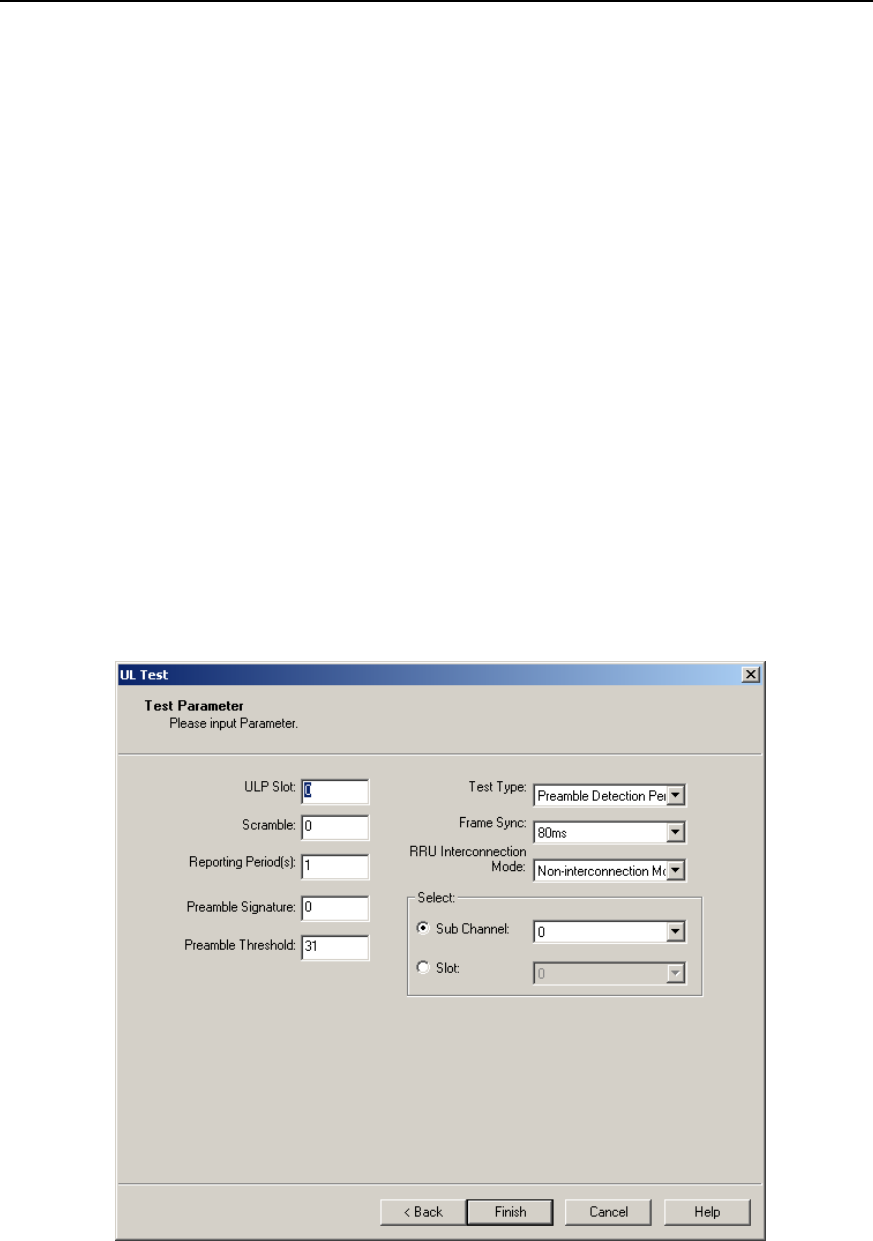
NodeB LMT User Guide Chapter 11 141 Test
II. Prerequisite
You have set the cell parameters related to this test.
III. Procedure
Follow the steps below to test the UL RACH 141:
1) Choose Maintenance Navigator -> Test Management. Then double-click the
141 Test subnode.
A dialog box opens up for your confirmation.
2) Click OK.
The system displays the 141 Test dialog box as shown in Figure 11-1.
3) Click Start RF Test….
The 141 test type dialog box opens up as shown in Figure 11-4.
4) Choose UL Multi-channel Test in the dialog box.
5) Click Next in the dialog box.
The UL Test Item dialog box opens up as shown in Figure 11-5.
6) Choose Main Diversity Test under RACH Test in the dialog box.
7) Click Next in the dialog box.
The Test Parameter dialog box opens up as shown in Figure 11-7.
Figure 11-7 Test Parameter dialog box (UL RACH test)
Table 11-5 describes the fields of the Test Parameter dialog box (UL RACH test).
Huawei Technologies Proprietary
11-15

NodeB LMT User Guide Chapter 11 141 Test
Table 11-5 Field description of Test Parameter dialog box (UL RACH test)
Field Description
ULP Slot
z To set the number of the slot that hosts the HULP (and/or
NULP) and HBBI which contain the demodulating DSPs
z Value range: 0 to 7
z 0 and 1 indicate the HBBI while 2 to 7 indicate the
HDLP/NDLP.
Scramble Value range: 0 to 8191
Reporting
Period(s)
z To set the reporting period of the test result
z Value range: 1 to 255
Preamble
Signature Value range: 0 to 15
Preamble
Threshold Value range: 27 to 35
Test Type
Value range: Preamble Detection Performance, Message
Demodulation Performance
z Preamble Detection Performance test: measures the
capture performance of RACH preamble, including false
alarm rate and detection rate.
z Message Demodulation Performance test: measures the
RACH message demodulation performance. The
demodulation performance refers to that on messages after
the system detects the access of a subscriber.
Frame Sync
z To set the intervals of frame synchronization signals output
by NMPT
z Value range: 20 ms, 40 ms, 80 ms
RRU
Interconnection
Mode
Value range: Non-interconnections Mode, Interconnection
Mode
Sub Channel
z If you select Sub Channel, Slot is unavailable.
z If you select Sub Channel, the test will have to be
conducted in the sub channel mode. The test device has to
support the test in this mode.
z Value range: 0 to 11, ALL
Slot
z If you select Slot, Sub Channel is unavailable.
z If you select Slot, the test will have to be conducted in the
time slot mode. The test device has to support the test in
this mode.
z Value range: 0 to 14, ALL
8) Set the parameters in the dialog box.
9) Click Finish.
A UL DPCH test is started. You are presented with the 141 Test dialog box. A
RACH Test subnode is added under the UL test started node at the same time.
Huawei Technologies Proprietary
11-16
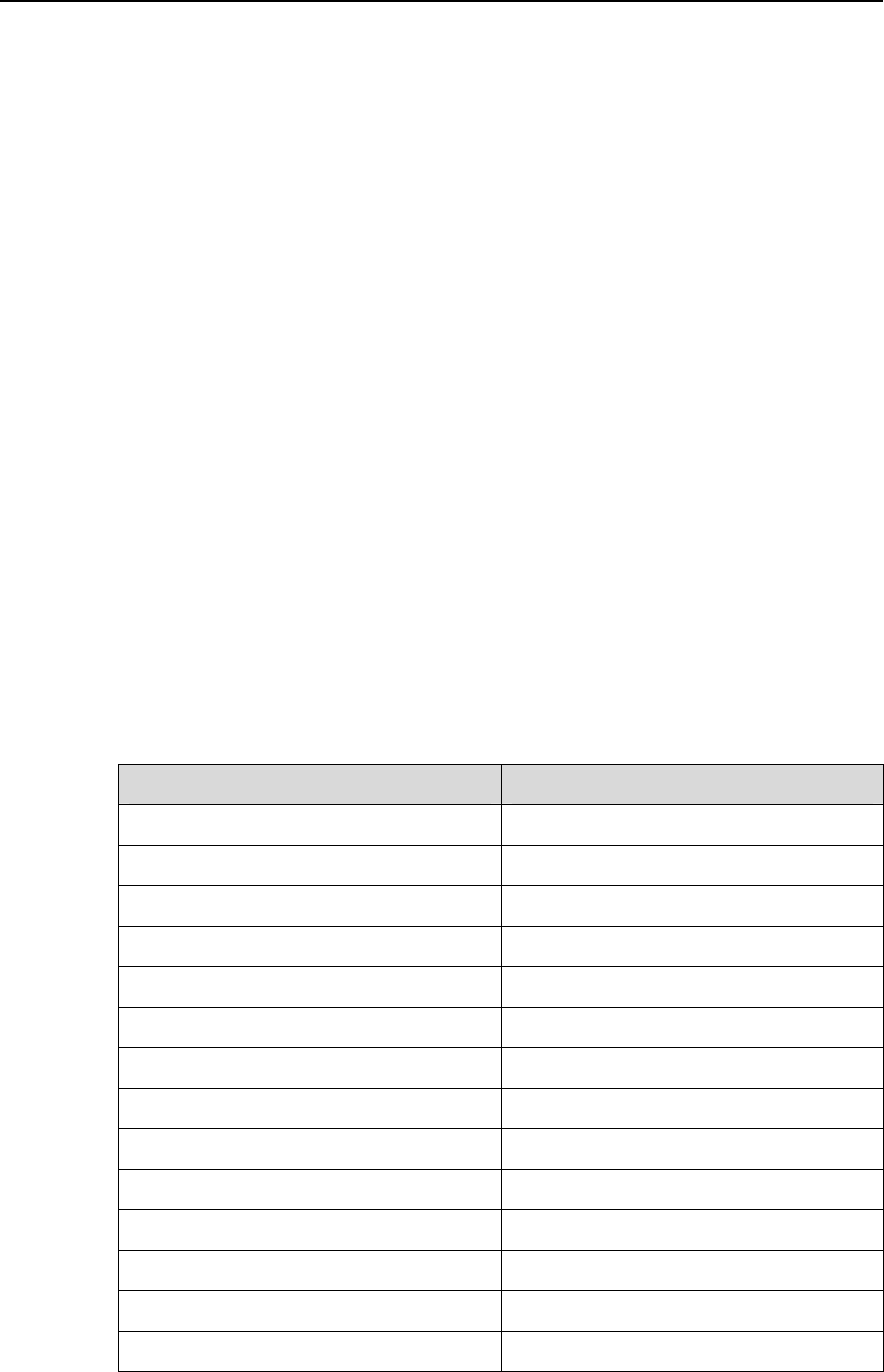
NodeB LMT User Guide Chapter 11 141 Test
10) Adjust the transmitted signals until the BER/BLER values meet the NodeB RF
performance requirements.
11) Record the test results.
12) Select the RACH Test subnode under UL test started. Then click Stop.
The test is stopped and the RACH Test subnode is deleted.
IV. Analysis of UL RACH Test Results
Compare the test results under different test environments with technical specifications
in the 3GPP TS25.141 protocol. If the results comply with the technical specifications,
the system passes the UL RACH test.
11.5 DL 141 Test
11.5.1 Introduction to DL 141 Test
The DL 141 test is to test the RF performance of the NodeB Tx channels. During the
test, the encoding DSPs in the HDLP/NDLP establish radio channels with specified
parameters according to different test modes.
Table 11-6 shows the relations between test items and test modes of DL 141 test.
Table 11-6 Relations between test items and test modes of DL 141 test
Test item Test mode
Max Transmit Power Test mode 1
CPICH Power Accuracy Test mode2
Frequency Error Test mode4
Transmit Intermodulation Test mode 1
IPDL Time Mask Test mode 1
Power Control Steps Test mode 2
Power Control Step or Dyn Range Test mode 2
Total Dynamic Range Test mode 4
Occupied Bandwidth Test mode 1
Spurious Emission Test mode 1
Spectrum Emission Mask Test mode 1
Adjacent Channel Leakage Power ratio Test mode 1
Modulation Accuracy Test mode 4
Peak Code Domain Error Test mode 3
Huawei Technologies Proprietary
11-17

NodeB LMT User Guide Chapter 11 141 Test
Different test modes correspond to different feature channels. The system
automatically establishes a feature channel for each test item based on the
corresponding test mode.
For details of the test mode, see technical specifications of the 3GPP TS25.141
protocol.
11.5.2 Testing Max Transmit Power
I. Introduction to Max Transmit Power Test
The maximum transmit power of NodeB is the average power of each carrier at the
antenna connector under certain conditions.
The max transmit power test is to test the difference between the maximum transmit
power and the rated transmit power of the NodeB within the entire frequency bands
under test.
II. Prerequisites
z You have set the cell parameters related to this test.
z You need to prepare a power meter.
III. Procedure
Follow the steps below to test the max transmit power:
1) Choose Maintenance Navigator -> Test Management. Then double-click the
141 Test subnode.
A dialog box opens up for your confirmation.
2) Click OK.
The system displays the 141 Test dialog box as shown in Figure 11-1.
3) Click Start RF Test….
The 141 test type dialog box opens up as shown in Figure 11-4.
4) Choose DL Test in the dialog box.
5) Click Next in the dialog box.
The DL Test Item dialog box opens up as shown in Figure 11-8.
Huawei Technologies Proprietary
11-18
NodeB LMT User Guide Chapter 11 141 Test
Figure 11-8 DL Test Item dialog box
6) Choose Max Transmit Power in the dialog box.
7) Click Finish.
A DL max transmit power test is started. You are presented with the 141 Test
dialog box. A maximum transmit power test subnode is added under DL test
started at the same time.
8) Read and record the test result from the power meter.
9) Select the Max Transmit Power test subnode under DL test started. Then click
Stop.
The max transmit power test is stopped and the Max Transmit Power test subnode is
deleted.
IV. Analysis of Max Transmit Power Test Result
Under normal test environment, the NodeB maximum transmit power is within ±2 dB of
the NodeB rated transmit power.
Huawei Technologies Proprietary
11-19

NodeB LMT User Guide Chapter 11 141 Test
11.5.3 Testing CPICH Power Accuracy
I. Introduction to CPICH Power Accuracy Test
The common pilot channel (CPICH) power accuracy refers to the deviation between
the ordered channel power and the pilot channel power measured at the antenna
interface. The CPICH power is a reference parameter for cell planning. This reference
parameter is broadcast to each UE through the DL BCH channel.
The CPICH power accuracy test is to verify the deviation between the ordered channel
power and the pilot channel power measured at the antenna interface.
II. Prerequisites
z You have set the cell parameters related to this test.
z You need to prepare an RF signal tester.
III. Procedure
Follow the steps below to test the CPICH power accuracy:
1) Choose Maintenance Navigator -> Test Management. Then double-click the
141 Test subnode.
A dialog box opens up for your confirmation.
2) Click OK.
The system displays the 141 Test dialog box as shown in Figure 11-1.
3) Click Start RF Test….
The 141 test type dialog box opens up as shown in Figure 11-4.
4) Choose DL Test in the dialog box.
5) Click Next in the dialog box.
The DL Test Item dialog box opens up as shown in Figure 11-8.
6) Choose CPICH Power Accuracy in the dialog box.
7) Click Finish.
A DL CPICH power accuracy test is started. You are presented with the 141 Test
dialog box. A CPICH Power Accuracy Test subnode is added under DL test
started at the same time.
8) Read and record the test result from the RF signal tester.
9) Select the CPICH Power Accuracy Test subnode under DL test started. Then
click Stop.
The CPICH power accuracy test is stopped and the CPICH Power Accuracy Test
subnode is deleted.
IV. Analysis of CPICH Power Accuracy Test Result
Under normal test environment, the measured CPICH power shall be within ±2.1 dB of
the ordered absolute value.
Huawei Technologies Proprietary
11-20

NodeB LMT User Guide Chapter 11 141 Test
11.5.4 Testing Frequency Error
I. Introduction to Frequency Error Test
Frequency error is the measure of the difference between the assigned frequency and
the actual NodeB transmit frequency. It is required to use the same source for both the
NodeB RF frequency and the data clock generation.
The frequency error test is to test the accuracy of the NodeB transmit frequency.
II. Prerequisite
You have set the cell parameters related to this test.
III. Procedure
Follow the steps below to test the frequency error:
1) Choose Maintenance Navigator -> Test Management. Then double-click the
141 Test subnode.
A dialog box opens up for your confirmation.
2) Click OK.
The system displays the 141 Test dialog box as shown in Figure 11-1.
3) Click Start RF Test….
The 141 test type dialog box opens up as shown in Figure 11-4.
4) Choose DL Test in the dialog box.
5) Click Next in the dialog box.
The DL Test Item dialog box opens up as shown in Figure 11-8.
6) Choose Frequency Error in the dialog box.
7) Click Next in the dialog box.
The DL test parameter dialog box opens up as shown in Figure 11-9.
Huawei Technologies Proprietary
11-21
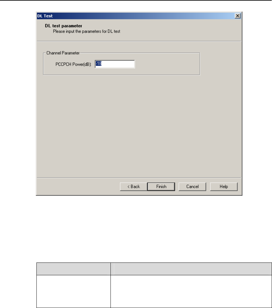
NodeB LMT User Guide Chapter 11 141 Test
Figure 11-9 DL test parameter dialog box (frequency error test)
Table 11-7 describes the fields of the DL test parameter dialog box (frequency error
test).
Table 11-7 Field description of DL test parameter dialog box (frequency error test)
Field Description
PCCPCH Power(dB)
To set the deviation from the maximum cell transmit
power
Value range: –3 dB to –44 dB
8) Set the parameters in the dialog box.
9) Click Finish. A frequency error test is started. You are presented with the 141 Test
dialog box. A Frequency Error Test subnode is added under DL test started at
the same time.
10) Read and record the test result from the tester.
11) Select the Frequency Error Test subnode under DL test started. Then click
Stop. The frequency error test is stopped and the Frequency Error Test subnode
is deleted.
Huawei Technologies Proprietary
11-22

NodeB LMT User Guide Chapter 11 141 Test
IV. Analysis of Frequency Error Test Result
Under normal test environment, the difference between measured transmit frequency
and actual transmit frequency is within ±0.05 ppm.
11.5.5 Testing Transmit Intermodulation
I. Introduction to Transmit Intermodulation Test
Transmit intermodulation performance is a measure of the capability of the transmitter
to inhibit the generation of signals in its non linear elements caused by presence of the
wanted signal and an interfering signal reaching the transmitter through the antenna.
The test is to verify the ability of the NodeB transmitter to restrict the generation of
intermodulation products in its non linear elements caused by presence of the wanted
signal and an interfering signal reaching the transmitter via the antenna to below
specified levels
II. Prerequisites
z You have set the cell parameters related to this test.
z You need to prepare an RF signal tester.
III. Procedure
Follow the steps below to test the transmit intermodulation:
1) Choose Maintenance Navigator -> Test Management. Then double-click the
141 Test subnode.
A dialog box opens up for your confirmation.
2) Click OK.
The system displays the 141 Test dialog box as shown in Figure 11-1.
3) Click Start RF Test….
The 141 test type dialog box opens up as shown in Figure 11-4.
4) Choose DL Test in the dialog box.
5) Click Next in the dialog box.
The DL Test Item dialog box opens up as shown in Figure 11-8.
6) Choose Transmit Intermodulation in the dialog box.
7) Click Finish.
A transmit intermodulation test is started. You are presented with the 141 Test
dialog box. A Transmitter Intermodulation Test subnode is added under DL test
started at the same time.
8) Select the cell to be tested under List of cells with parameters of the 141 Test
dialog box.
9) Read and record the test result from the tester.
Huawei Technologies Proprietary
11-23

NodeB LMT User Guide Chapter 11 141 Test
10) Select the Transmit Intermodulation test subnode under DL test started. Then
click Stop.
The test is stopped and the Transmit Intermodulation test subnode is deleted.
IV. Analysis of Transmit Intermodulation Test Result
Interference signals are generated through NodeB. You can generate one more test
signal in another cell with the procedure above, and inject the signal into the cell under
test as interference signal through external test devices.
The power of the interference WCDMA signal shall be 30 dB lower than that of the
wanted signal. The frequency of the interference WCDMA signal shall be 5 MHz,
10 MHz and 15 MHz offset below the first or above the last carrier frequency used.
Under normal test environment, the spectrum emission mask, ACLR and spurious
emissions shall meet the technical specifications defined in the protocol in case of
inverse intermodulation interference.
11.5.6 Testing IPDL Time Mask
I. Introduction to IPDL Time Mask Test
Idle period of DL (IPDL) refers to the idle period of DL signal. During IPDL, the NodeB
shuts down all the DL channels temporarily to minimize interference to the UE during
measuring DL signals in different cells. Therefore, the accuracy of measurement for DL
signals in neighboring NodeBs is improved.
The IPDL time mask test is to check whether the power active/idle suppression of
NodeB DL signals meets requirements during the test time specified by IPDL.
II. Prerequisites
z You have set the cell parameters related to this test.
z You need to prepare a power meter.
III. Procedure
Follow the steps below to test the IPDL time mask:
1) Choose Maintenance Navigator -> Test Management. Then double-click the
141 Test subnode.
A dialog box opens up for your confirmation.
2) Click OK.
The system displays the 141 Test dialog box as shown in Figure 11-1.
3) Click Start RF Test….
The 141 test type dialog box opens up as shown in Figure 11-4.
Huawei Technologies Proprietary
11-24

NodeB LMT User Guide Chapter 11 141 Test
4) Choose DL Test in the dialog box.
5) Click Next in the dialog box.
The DL Test Item dialog box opens up as shown in Figure 11-8.
6) Choose IPDL Time Mask in the dialog box.
7) Click Finish.
An IPDL time mask test is started. You are presented with the 141 Test dialog box.
An IPDL Time Mask test subnode is added under DL test started at the same
time.
8) Read and record the test result from the tester.
9) Select the IPDL Time Mask test subnode under DL test started. Then click Stop.
The IPDL time mask test is stopped and the IPDL Time Mask Test subnode is deleted.
IV. Analysis of IPDL Time Mask Test Result
There are two items of the IPDL time mask test:
z idle time
z power active/idle suppression
The results of the test items must be consistent with the corresponding requirement.
11.5.7 Testing Power Control Steps
I. Introduction to Power Control Steps Test
Inner loop power control in the DL is the transmission ability of the NodeB transmitter. It
adjusts the DL transmitter output power according to the corresponding TPC symbols
received in the UL.
The power control step is the required step change in the DL transmitter output power
of a code channel in response to the corresponding power control command.
The power control step test is to verify whether the DL power control step size and
response meet relevant requirements.
II. Prerequisites
z You have set the cell parameters related to this test.
z You need to prepare a signal generator.
III. Procedure
Follow the steps below to test the power control steps:
1) Choose Maintenance Navigator -> Test Management. Then double-click the
141 Test subnode.
A dialog box opens up for your confirmation.
Huawei Technologies Proprietary
11-25
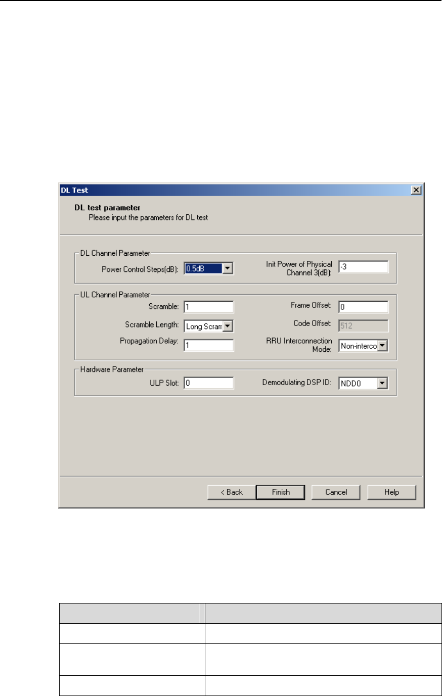
NodeB LMT User Guide Chapter 11 141 Test
2) Click OK.
The system displays the 141 Test dialog box as shown in Figure 11-1.
3) Click Start RF Test….
The 141 test type dialog box opens up as shown in Figure 11-4.
4) Choose DL Test in the dialog box.
5) Click Next in the dialog box.
The DL Test Item dialog box opens up as shown in Figure 11-8.
6) Choose Power Control Steps in the dialog box.
7) Click Next in the dialog box.
The DL test parameter dialog box opens up as shown in Figure 11-10.
Figure 11-10 DL test parameter dialog box (power control steps test)
Table 11-8 describes the fields of the DL test parameter dialog box.
Table 11-8 Field description of DL test parameter (power control steps test)
Field Description
Power Control Steps (dB) Value range: 0.5 dB, 1 dB, 1.5 dB, 2 dB
Init Power of Physical
Channel 3 (dB) Value range: –3 dB to –45 dB
Scramble Value range: 0 to 16777215
Huawei Technologies Proprietary
11-26

NodeB LMT User Guide Chapter 11 141 Test
Field Description
Scramble Length Value range: Long Scramble, Short Scramble
Frame Offset Value range: 0 to 255
Code Offset Unavailable value: 512
Propagation Delay Value range: 0 to 255
RRU Interconnection Mode Value range: Non-interconnection Mode,
Interconnection Mode
ULP Slot
To set the number of the slot that hosts the HULP
(and/or NULP) and HBBI which contain the
demodulating DSPs
Value range: 0 to 7
0 and 1 indicate the HBBI while 2 to 7 indicate the
HDLP/NDLP.
Demodulating DSP ID
One HULP (and/or NULP) has two demodulating
DSPs. One HBBI has one demodulating DSP.
When you set the ULP Slot as 0 or 1, the value can
be NEC0 only.
When you set the ULP Slot as any number from 2
to 7, the value can be NEC0 or NEC1.
8) Set the parameters in the dialog box.
9) Click Finish.
A power control steps test is started. You are presented with the 141 Test dialog
box. A Power Control Step test subnode is added under DL test started at the
same time.
10) Read and record the test result from the tester.
11) Select the Power Control Step test subnode under DL test started. Then click
Stop.
The power control steps test is stopped and the Power Control Step test subnode is
deleted.
IV. Analysis of Power Control Steps Test Result
Perform Up/Down tests based on different power control steps. The power changes by
1 dB after one power control with the power step of 1 dB. The power changes by 10 dB
after 10 power controls with the power step of 1 dB. The same is true for the power step
of 0.5 dB.
Under normal test environment, the measured power control steps must satisfy Table
11-9 (single step) and Table 11-10 (10 consecutive steps).
Huawei Technologies Proprietary
11-27

NodeB LMT User Guide Chapter 11 141 Test
Table 11-9 Power control step requirements (single step)
Transmitter Power Control Step Tolerance
1 dB Step 0.5 dB Step
TPC Command in DL
Lower Upper Lower Upper
Up (TPC command 1) +0.5 dB +1.5 dB +0.25 dB +0.75 dB
Down (TPC command 0)–0.5 dB –1.5 dB –0.25 dB –0.75 dB
Table 11-10 Power control step requirements (10 consecutive steps)
Transmitter Combined Output Power Change
Tolerance after 10 Consecutive Equal Commands
(Up or Down)
1 dB Step 0.5 dB Step
TPC Command in DL
Lower Upper Lower Upper
Up (TPC command 1) +8 dB +12 dB +4 dB +6 dB
Down (TPC command 0)–8 dB –12 dB –4 dB –6 dB
11.5.8 Testing Power Control Step or Dynamic Range
I. Introduction to Power Control Step or Dyn Range Test
The power control dynamic range is the difference between the maximum and the
minimum code domain powers of a code channel under specified conditions.
The test is to check that the power control dynamic range of the code channel meets
the requirement.
II. Prerequisites
z You have set the cell parameters related to this test.
z You need to prepare a signal generator.
III. Procedure
Follow the steps below to test the power control step or dynamic range:
1) Choose Maintenance Navigator -> Test Management. Then double-click the
141 Test subnode.
A dialog box opens up for your confirmation.
2) Click OK.
The system displays the 141 Test dialog box as shown in Figure 11-1.
Huawei Technologies Proprietary
11-28
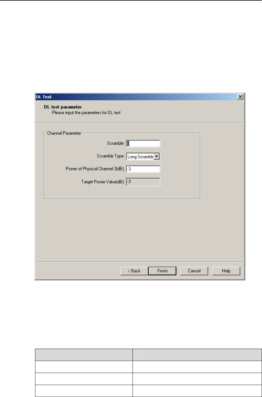
NodeB LMT User Guide Chapter 11 141 Test
3) Click Start RF Test….
The 141 test type dialog box opens up as shown in Figure 11-4.
4) Choose DL Test in the dialog box.
5) Click Next in the dialog box. The DL Test Item dialog box opens up as shown in
Figure 11-8.
6) Choose Power Control Step or Dyn Range in the dialog box.
7) Click Next in the dialog box. The DL test parameter dialog box opens up as
shown in Figure 11-11.
Figure 11-11 DL test parameter dialog box (power control step or dynamic range test)
Table 11-11 describes the fields of the DL test parameter dialog box (power control step
or dynamic range test).
Table 11-11 Field description of DL test parameter dialog box
Field Description
Scramble Value range: 0 to 16777215
Scramble Type Value range: Long Scramble, Short Scramble
Power of Physical Channel 3 (dB) Value range: –3 dB to –45 dB
Huawei Technologies Proprietary
11-29

NodeB LMT User Guide Chapter 11 141 Test
Field Description
Target Power Value
Power change at each time
Precision: 0.5 dB
8) Set the parameters in the dialog box.
9) Click Finish. A power control step or dynamic range test is started. You are
presented with the 141 Test dialog box. A Power Control Step or Dynamic
Range test subnode is added under DL test started at the same time.
10) Record the test result from the tester as result 1.
11) Select this subnode and click Parameter… in the 141 Test dialog box. You are
presented with Test Parameter dialog box.
12) Set Power of Physical Channel 3 to a lower value if the initial value is -3 dB or to
a higher value if the initial value is –45 dB.
13) Record the test result from the tester as result 2.
14) Repeat steps 10) to 12) until the value after Power of Physical Channel 3
reaches the other boundary, for example, –45dB. Record the results in turn.
15) Select the Power Control Step or Dynamic Range test subnode under DL test
started. Then click Stop.
The test is stopped and the Power Control Step or Dynamic Range test subnode is
deleted.
IV. Analysis of Power Control Step or Dynamic Range Test Result
Under normal test environment, the power control step size or dynamic range shall
satisfy the following requirements:
z Maximum code domain power ≥ NodeB maximum output power –3 dB
z Minimum code domain power ≤ NodeB maximum output power –28 dB
11.5.9 Testing Total Dynamic Range
I. Introduction to Total Dynamic Range Test
Power control dynamic range is difference between the maximum and the minimum
transmit output power of a code channel for a specified reference condition.
This test is to verify that the minimum power control dynamic range is meet the
requirement
II. Prerequisites
z You have set the cell parameters related to this test.
z You need to prepare a signal generator.
Huawei Technologies Proprietary
11-30

NodeB LMT User Guide Chapter 11 141 Test
III. Procedure
Follow the steps below to test this total dynamic range:
1) Choose Maintenance Navigator -> Test Management. Then double-click the
141 Test subnode.
A dialog box opens up for your confirmation.
2) Click OK.
The system displays the 141 Test dialog box as shown in Figure 11-1.
3) Click Start RF Test….
The 141 test type dialog box opens up as shown in Figure 11-4.
4) Choose DL Test in the dialog box.
5) Click Next in the dialog box.
The DL Test Item dialog box opens up as shown in Figure 11-8.
6) Choose Total Dynamic Range in the dialog box.
7) Click Finish.
A total dynamic range test is started. You are presented with the 141 Test dialog
box. A Dynamic Range for Total Power test subnode is added under DL test
started at the same time.
8) Read and record the test result from the power meter.
9) Select the Dynamic Range for Total Power test subnode under DL test started.
Then click Stop.
The test is stopped and the Dynamic Range for Total Power test subnode is deleted.
IV. Analysis of Total Dynamic Range Test Result
Under normal test environment, the dynamic range of total DL power, which is equal to
the maximum transmit power minus minimum transmit power, is no smaller than 18 dB.
11.5.10 Testing Occupied Bandwidth
I. Introduction to Occupied Bandwidth Test
The occupied bandwidth is the width of a frequency band such that, below the lower
and above the upper frequency limits, the mean powers emitted are each equal to a
specified percentage of 0.5% of the total mean transmitted power. Therefore, the total
power in the occupied bandwidth shall be no less than 99% of the total mean
transmitted power.
The test is to verify whether the occupied bandwidth of a channel meets the
requirement.
II. Prerequisites
z You have set the cell parameters related to this test.
Huawei Technologies Proprietary
11-31

NodeB LMT User Guide Chapter 11 141 Test
z You need to prepare a signal generator.
III. Procedure
Follow the steps below to test the occupied bandwidth:
1) Choose Maintenance Navigator -> Test Management. Then double-click the
141 Test subnode.
A dialog box opens up for your confirmation.
2) Click OK.
The system displays the 141 Test dialog box as shown in Figure 11-1.
3) Click Start RF Test….
The 141 test type dialog box opens up as shown in Figure 11-4.
4) Choose DL Test in the dialog box.
5) Click Next in the dialog box.
The DL Test Item dialog box opens up as shown in Figure 11-8.
6) Choose Occupied Bandwidth in the dialog box.
7) Click Finish.
An occupied bandwidth test is started. You are presented with the 141 Test dialog
box. An Occupied Bandwidth test subnode is added under DL test started at
the same time.
8) Read and record the test result from the tester.
9) Select the Occupied Bandwidth test subnode under DL test started. Then click
Stop.
The test is stopped and the Occupied Bandwidth test subnode is deleted.
IV. Analysis of Occupied Bandwidth Test Result
Under normal test environment, the occupied bandwidth of chip rate at 3.84 Mcps shall
be less than 5 MHz.
11.5.11 Testing Spurious Emission
I. Introduction to Spurious Emission Test
Spurious emissions include harmonic emission, parasitic emission, intermodulation
products and frequency conversion products produced by unwanted transmitter effects.
These emissions interfere in devices within other frequency bands. The test is to check
that special frequency bands meet relevant standards. It is applicable to multi-carrier
cases and specified frequency ranges, which are more than 12.5 MHz under the first
carrier frequency used or more than 12.5 MHz above the last carrier frequency used.
The detection is conducted in the true RMS level mode or in the true average level
mode.
Huawei Technologies Proprietary
11-32

NodeB LMT User Guide Chapter 11 141 Test
II. Prerequisites
z You have set the cell parameters related to this test.
z You need to prepare a signal generator.
III. Procedure
Follow the steps below to test the spurious emission:
1) Choose Maintenance Navigator -> Test Management. Then double-click the
141 Test subnode.
A dialog box opens up for your confirmation.
2) Click OK.
The system displays the 141 Test dialog box as shown in Figure 11-1.
3) Click Start RF Test….
The 141 test type dialog box opens up as shown in Figure 11-4.
4) Choose DL Test in the dialog box.
5) Click Next in the dialog box.
The DL Test Item dialog box opens up as shown in Figure 11-8.
6) Choose Spurious Emission in the dialog box.
7) Click Finish.
A spurious emission test is started. You are presented with the 141 Test dialog box.
A Spurious Emission subnode is added under DL test started at the same time.
8) Read and record the test result from the tester.
9) Select the Spurious Emission test subnode under DL test started. Then click
Stop.
The test is stopped and the Spurious Emission test subnode is deleted.
IV. Analysis of Spurious Emission Test Result
Spurious emission test categories include Category A, Category B, protection of
special frequency band. The settings of RF signal tester vary with the test categories.
Under normal test environment, the test result must satisfy Table 11-12, Table 11-13
and Table 11-14.
Table 11-12 Spurious emission requirements (Category A)
Band Max level Measurement bandwidth
9 kHz to 150 kHz 1 kHz
150 kHz to 30 MHz 10 kHz
30 MHz to 1 GHz 100 kHz
1 GHz to 12.75 GHz
–13 dBm
1 MHz
Huawei Technologies Proprietary
11-33

NodeB LMT User Guide Chapter 11 141 Test
Table 11-13 Spurious emission requirements (Category B)
Band Max level Measurement bandwidth
9 kHz to 150 kHz 1 kHz
150 kHz to 30 MHz 10 kHz
30 MHz to 1 GHz
–36 dBm
100 kHz
1 GHz to Max (fc1-60 MHz,
2100 MHz –30 dBm 1 MHz
Max (fc1-60 MHz, 2100 MHz)
to Max (fc1-50 MHz, 2100
MHz)
–25 dBm 1 MHz
Max (fc1-50 MHz, 2100 MHz)
to Min (fc2+50 MHz, 2180
MHz)
–15 dBm 1 MHz
Min (fc2+50 MHz, 2180 MHz)
to Min (fc2+60 MHz, 2180
MHz)
–25 dBm 1 MHz
Min (fc2+60 MHz, 2180 MHz)
to 12.75 GHz –30 dBm 1 MHz
Table 11-14 Spurious emission requirements (protection of special frequency band)
Band description Band Max level Measurement
bandwidth
Receive band 1920 MHz to 1980
MHz –96 dBm 100 kHz
Co-existing with GSM900 921 MHz to
960 MHz –57 dBm 100 kHz
GSM900 BTS co-located
with UTRS NodeB
876 MHz to
915 MHz –98 dBm 100 kHz
Co-existing with
DSC1800
1805 MHz to
1880 MHz –47 dBm 100 kHz
DSC1800 BTS co-located
with UTRS NodeB
1710 MHz to
1785 MHz –98 dBm 100 kHz
Co-existing with PHS 1893.5 MHz to
1919.6 MHz –41 dBm 300 kHz
Co-existing with services
in adjacent frequency
bands
2100 MHz to
2105 MHz
–30+3.4
(f-2100 MH
z)
1 MHz
Co-existing with services
in adjacent frequency
bands
2175 MHz to
2180 MHz
–30+3.4
(2180MHz-f
)
1 MHz
Huawei Technologies Proprietary
11-34

NodeB LMT User Guide Chapter 11 141 Test
11.5.12 Testing Spectrum Emission
I. Introduction to Spectrum Emission Mask Test
Emissions shall not exceed the maximum level for the appropriate NodeB maximum
output power, in the frequency range from Df =2.5 MHz to f_offsetmax from the carrier
frequency. These level requirements form a spectrum emission mask.
The test is to verify the out-of-band spectrum leakage of the NodeB.
II. Prerequisites
z You have set the cell parameters related to this test.
z You need to prepare a signal generator.
III. Procedure
Follow the steps below to test the spectrum emission:
1) Choose Maintenance Navigator -> Test Management. Then double-click the
141 Test subnode.
A dialog box opens up for your confirmation.
2) Click OK.
The system displays the 141 Test dialog box as shown in Figure 11-1.
3) Click Start RF Test….
The 141 test type dialog box opens up as shown in Figure 11-4.
4) Choose DL Test in the dialog box.
5) Click Next in the dialog box.
The DL Test Item dialog box opens up as shown in Figure 11-8.
6) Choose Spectrum Emission Mask in the dialog box.
7) Click Finish.
A spectrum emission mask test is started. You are presented with the 141 Test
dialog box. A Spectrum Output Template test subnode is added under DL test
started at the same time.
8) Read and record the test result from the tester.
9) Select the Spectrum Output Template test subnode under DL test started.
Then click Stop.
The test is stopped and the Spectrum Output Template test subnode is deleted.
IV. Analysis of Spectrum Emission Mask Test Result
Under normal test environment, the test result must satisfy the technical specifications
in protocol of 3GPP TS25.141.
Huawei Technologies Proprietary
11-35

NodeB LMT User Guide Chapter 11 141 Test
11.5.13 Testing ACLR
I. Introduction to ACLR Test
Adjacent channel leakage power ratio (ACLR) is the ratio of the transmitted power
within the specified carrier frequency band to the mean power leaked into the adjacent
carrier band.
The test is to verify whether the adjacent channel leakage power radio meets the
requirements for adjacent channel interference.
II. Prerequisites
z You have set the cell parameters related to this test.
z You need to prepare a signal generator.
III. Procedure
Follow the steps below to test the ACLR:
1) Choose Maintenance Navigator -> Test Management. Then double-click the
141 Test subnode.
A dialog box opens up for your confirmation.
2) Click OK.
The system displays the 141 Test dialog box as shown in Figure 11-1.
3) Click Start RF Test….
The 141 test type dialog box opens up as shown in Figure 11-4.
4) Choose DL Test in the dialog box.
5) Click Next in the dialog box.
The DL Test Item dialog box opens up as shown in Figure 11-8.
6) Choose Adjacent Channel Leakage Power ratio in the dialog box.
7) Click Finish.
An ACLR test is started. You are presented with the 141 Test dialog box. An
Adjacent Channel Leakage Power ratio test subnode is added under DL test
started at the same time.
8) Read and record the test result from the tester.
9) Select the Adjacent Channel Leakage Power ratio test subnode under UL test
started. Then click Stop.
The test is stopped and the Adjacent Channel Leakage Power ratio test subnode is
deleted.
IV. Analysis of ACLR Test Result
Under normal test environment, the ACLR test result must satisfy Table 11-15.
Huawei Technologies Proprietary
11-36
NodeB LMT User Guide Chapter 11 141 Test
Table 11-15 ACLR requirements
NodeB channel offset below first or above last carrier
frequency used ACLR limit
5 MHz > 45 dB
10 MHz > 50 dB
Note:
z Matched filter used the filter (Root Raised Cosine and roll-off 0.22) with a noise
power bandwidth equal to the chip rate.
z The detection is conducted either in the true RMS level mode or in the true average
level mode. Measure the ACLR for 5 MHz and 10 MHz offsets on both sides of
channel frequency.
11.5.14 Testing EVM
I. Introduction to EVM Test
Error vector magnitude (EVM) shows the difference between the reference waveform
and the measured waveform.
In this manual, EVM refers to the modulation accuracy.
II. Prerequisites
z You have set the cell parameters related to this test.
z You need to prepare a signal generator.
III. Procedure
Follow the steps below to test the modulation accuracy:
1) Choose Maintenance Navigator -> Test Management. Then double-click the
141 Test subnode.
A dialog box opens up for your confirmation.
2) Click OK.
The system displays the 141 Test dialog box as shown in Figure 11-1.
3) Click Start RF Test….
The 141 test type dialog box opens up as shown in Figure 11-4.
4) Choose DL Test in the dialog box.
5) Click Next in the dialog box.
The DL Test Item dialog box opens up as shown in Figure 11-8.
Huawei Technologies Proprietary
11-37

NodeB LMT User Guide Chapter 11 141 Test
6) Choose Modulation Accuracy in the dialog box.
7) Click Next in the dialog box.
The DL test parameter dialog box opens up as shown in Figure 11-9.
8) Set the parameters in the dialog box.
9) Click Finish.
A modulation accuracy test is started. You are presented with the 141 Test dialog
box. A Modulation Accuracy test subnode is added under DL test started at the
same time.
10) Record the test result from the tester as result 1.
11) Select this subnode and click Parameter… in the 141 Test dialog box. You are
presented with Test Parameter dialog box.
12) Change PCCPCH Power into another boundary value in the dialog box.
13) Repeat step 9). Record the test result from the tester as result 2.
14) Select the Modulation Accuracy test subnode under DL test started. Then click
Stop.
The modulation accuracy test is stopped and the Modulation Accuracy test subnode
is deleted.
IV. Analysis of EVM Test Result
Compare two test results with standard values. Under normal test environment, the
EVM shall be smaller than 17.5%.
11.5.15 Testing PCDE
I. Introduction to PCDE Test
The code domain error (PCDE) is calculated by projecting the error vector onto the
code domain. It is expressed in dB. The PCDE is defined as the maximum value of the
code domain error for all codes at a specific spreading factor.
The test is to discover and limit inter-code cross-talk.
II. Prerequisites
z You have set the cell parameters related to this test.
z You need to prepare a signal generator.
III. Procedure
Follow the steps below to test the PCDE:
1) Choose Maintenance Navigator -> Test Management. Then double-click the
141 Test subnode.
A dialog box opens up for your confirmation.
Huawei Technologies Proprietary
11-38

NodeB LMT User Guide Chapter 11 141 Test
2) Click OK.
The system displays the 141 Test dialog box as shown in Figure 11-1.
3) Click Start RF Test….
The 141 test type dialog box opens up as shown in Figure 11-4.
4) Choose DL Test in the dialog box.
5) Click Next in the dialog box.
The DL Test Item dialog box opens up as shown in Figure 11-8.
6) Choose Peak Code Domain Error in the dialog box.
7) Click Finish.
A peak code domain error test is started. You are presented with the 141 Test
dialog box. A Peak Code Domain Error test subnode is added under DL test
started at the same time.
8) Read and record the test result from the tester.
9) Select the Peak Code Domain Error test subnode under DL test started. Then
click Stop.
The test is stopped and the Peak Code Domain Error test subnode is deleted.
IV. Analysis of PCDE Test Result
Under normal test environment, the peak code domain error must be smaller than
–33 dB at spreading factor 256.
Huawei Technologies Proprietary
11-39

NodeB LMT User Guide Table of Contents
Table of Contents
Chapter 12 Managing NodeB Clock........................................................................................... 12-1
12.1 About This Chapter........................................................................................................ 12-1
12.2 Overview of NodeB Clock.............................................................................................. 12-1
12.2.1 Principle of Clock ................................................................................................ 12-1
12.2.2 Center Frequency DA Value ............................................................................... 12-1
12.2.3 Current Frequency DA Value.............................................................................. 12-1
12.2.4 Initial DA Value.................................................................................................... 12-2
12.3 Querying Clock Status ................................................................................................... 12-2
12.3.1 Overview of Querying Clock Status .................................................................... 12-2
12.3.2 Introduction to Clock Status ................................................................................ 12-2
12.3.3 Querying Current Clock Status ........................................................................... 12-3
12.3.4 Querying History Clock Record........................................................................... 12-4
12.4 Managing NodeB Clock Source..................................................................................... 12-5
12.4.1 Overview ............................................................................................................. 12-5
12.4.2 Introduction to NodeB Clock Source................................................................... 12-5
12.4.3 Setting NodeB Clock Work Mode........................................................................ 12-5
12.4.4 Setting NodeB Clock Source............................................................................... 12-6
12.4.5 Testing NodeB Clock Source Quality.................................................................. 12-7
12.5 Setting NodeB Clock Frequency.................................................................................... 12-7
12.5.1 Overview ............................................................................................................. 12-7
12.5.2 Introduction to Clock Frequency Values ............................................................. 12-7
12.5.3 Setting NodeB Clock Center Frequency ............................................................. 12-7
12.5.4 Setting NodeB Clock Current Frequency............................................................ 12-8
Huawei Technologies Proprietary
i

NodeB LMT User Guide Chapter 12 Managing NodeB Clock
Chapter 12 Managing NodeB Clock
12.1 About This Chapter
This chapter presents knowledge of the NodeB clock and means of maintaining the
clock.
12.2 Overview of NodeB Clock
12.2.1 Principle of Clock
The NodeB clock module is mounted on the NMPT to provide timing signals for the
NodeB. Under normal conditions, the NodeB clock works in the phase-lock mode. It
keeps precision by tracing the assigned high-precision reference clock source.
There are three reference clock sources for the NodeB:
z Iub interface clock
z GPS clock
z External clock
Only one clock synchronization mode is available at the same time.
When the NodeB clock synchronization source is faulty, the NodeB works in free-run
mode. This enables the NodeB clock to run for another 90 days.
12.2.2 Center Frequency DA Value
The center frequency value is also called center DA value. When the NodeB is in
normal operation, the master clock frequency is about 10 MHz, which is output from the
Oven Controlled Crystal Oscillator (OCXO) in the NMPT. Fine tuning on the main clock
frequency can be realized by adjusting voltage on the OCXO. The quantized value of
the voltage corresponding to the exact 10 MHz is referred to as the center frequency
DA.
12.2.3 Current Frequency DA Value
The current frequency DA value is also referred to as current DA value.
z When the NodeB clock works in the free-run mode, the current DA value is the
same as the center DA value.
Huawei Technologies Proprietary
12-1

NodeB LMT User Guide Chapter 12 Managing NodeB Clock
z When the NodeB is using a reference clock source, the current DA value of the
NodeB clock synchronizes with the frequency of the clock source. Namely, the
current DA value is adjusted according to the frequency difference of the clock
source during the software phase-locking.
z If the external clock source stays locked for seven consecutive days, it shows that
the clock source is stable. In that case, the clock module shall overwrite the center
DA value with the current DA value. Upon resetting the NMPT or the NodeB, the
current DA value shall be overwritten with the center DA value.
12.2.4 Initial DA Value
The initial DA value is the center frequency DA value preset in the NMPT before its
delivery. When the NodeB is started for the first time, this value is written into the
configuration file as the center frequency DA value. Therefore, the initial DA value can
be regarded as the center frequency DA value preset before the NodeB delivery.
12.3 Querying Clock Status
12.3.1 Overview of Querying Clock Status
You can query the following clock status:
z Current clock status
z History clock status
12.3.2 Introduction to Clock Status
I. Current Clock Status
The current clock status may include:
z Configured clock source
z Configured clock source status
z Configured work mode
z Current work mode
z Clock status
z Center DA
z Current DA
z Original DA
II. History Clock Status
The history clock status may include:
z Time
Huawei Technologies Proprietary
12-2
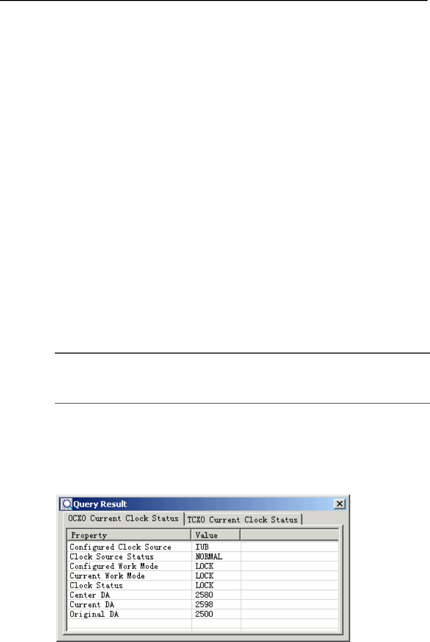
NodeB LMT User Guide Chapter 12 Managing NodeB Clock
z Clock Status
z Current DA
z Center DA
12.3.3 Querying Current Clock Status
I. Introduction
You can query the current clock status to
z Know the running status of the NodeB clock
z Check the clock modifications
z Check whether the clock needs to be maintained
II. Prerequisite
None.
III. Procedure
Follow the steps below to query the current clock status:
1) Select the NMPT on the equipment panel.
Note:
For the DBS3800, select the MBBU/HBBU on the equipment panel.
2) Right-click on the NMPT.
A shortcut menu opens up.
3) Select Display Current Clock Status.
The Query Result dialog box opens up as shown in Figure 12-1 and Figure 12-2.
Figure 12-1 OCXO Current Clock Status in Query Result dialog box
Huawei Technologies Proprietary
12-3
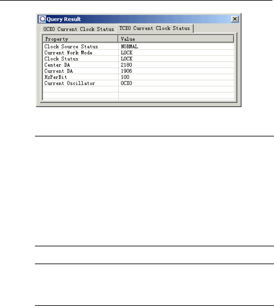
NodeB LMT User Guide Chapter 12 Managing NodeB Clock
Figure 12-2 TCXO Current Clock Status in Query Result dialog box
Note:
For the macro NodeB,
z You can query the current clock status only when the active and standby NMPTs
work well.
z You can query the clocks on the active and standby NMPTs which are independent
from each other.
z In the query result, parameters for the active and standby NMPTs may be
inconsistent except for those in the clock source and clock status.
For the DBS3800, you can query the current clock status only when the MBBU or HBBI
works well.
Note:
You can query the current NodeB clock status by the MML command of DSP
CURRCLK.
12.3.4 Querying History Clock Record
I. Introduction
You may query the history clock record to know the change in current frequency DA
value. The history clock record stores details about changes of the clock DA value.
II. Prerequisite
None.
Huawei Technologies Proprietary
12-4

NodeB LMT User Guide Chapter 12 Managing NodeB Clock
III. Procedure
You can query the history clock status by the MML command of LST CLKRECORD.
12.4 Managing NodeB Clock Source
12.4.1 Overview
Managing the clock source refers to
z Setting NodeB clock work mode
z Setting NodeB clock source
z Testing NodeB clock source quality
12.4.2 Introduction to NodeB Clock Source
The NodeB needs to lock to an external clock to calibrate its master clock frequency.
Then the external clock is the clock source.
There are three clock sources available for the NodeB, including
z Iub interface clock source: It is the default setting by the system. The NodeB
extracts clock signals from the Iub interface between NodeB and RNC as its
reference clock source.
z External clock source: The NodeB locks to a 2.048 MHz external clock as its
reference clock source. The clock source can be a BITS clock or a clock at the
synchronous interface of the SDH equipment.
z GPS clock source: The NodeB uses the clock signals generated from the GPS
receive card built in the NMPT as its reference clock source.
12.4.3 Setting NodeB Clock Work Mode
I. Introduction
Caution:
z This operation causes faults easily.
z Do Not execute this command without Huawei technical support.
The NodeB clock work modes include lock mode and free mode.
z The clock work mode can be set to "lock" only when there is an external reference
clock source.
Huawei Technologies Proprietary
12-5

NodeB LMT User Guide Chapter 12 Managing NodeB Clock
z When the clock work mode is "free", the NodeB clock works in the free-run mode
and the clock source does not work.
z If the clock source is faulty and needs calibrating, set the work mode into the free
mode and then calibrate the frequency value to the center frequency DA value.
This action is usually performed together with actions in subsection 12.5.4
"Setting NodeB Clock Current Frequency ".
z You need to set the NodeB clock work mode before setting the current frequency
value.
II. Prerequisite
Be sure to set the clock work mode one minute after the NodeB initialization.
III. Procedure
You can modify the NodeB clock work mode by the MML of MOD CLKMODE only.
12.4.4 Setting NodeB Clock Source
I. Introduction
The NodeB needs to lock to an external clock to calibrate its master clock frequency.
Then the external clock is the clock source.
You must select a proper clock source for the NodeB before it starts running. The
system automatically locks to the clock source after setting the clock source. There is
no need for other manual settings.
II. Prerequisites
Be cautious about the following items before you set the clock source:
z To use the Iub interface clock or GPS clock, make sure the clock source is
available.
z To use the GPS clock, make sure there is a GPS card on the NMPT. If there is a
GPS card, execute the MML command of DSP GPS to check whether the GPS
clock source is available. You can set the clock source only when the GPS clock
source is available.
z To use the Iub interface clock, set the Iub interface and the Iub interface board
from which the NodeB extracts clock signals. And then check the settings by the
MML commands of DSP IUBCLK, ADD IUBCLK and RMV IUBCLK.
III. Procedure
You can set the reference clock source by the MML command of MOD CLKSRC.
Huawei Technologies Proprietary
12-6
NodeB LMT User Guide Chapter 12 Managing NodeB Clock
12.4.5 Testing NodeB Clock Source Quality
See section 9.6 "Clock Test".
12.5 Setting NodeB Clock Frequency
12.5.1 Overview
Setting the NodeB clock frequency includes
z Setting NodeB Clock Center Frequency
z Setting NodeB Clock Current Frequency
12.5.2 Introduction to Clock Frequency Values
For details, see 12.2.2 "Center Frequency DA Value", 12.2.3 "Current Frequency DA
Value" and 12.2.4 "Initial DA Value".
12.5.3 Setting NodeB Clock Center Frequency
I. Introduction
Caution:
z This operation causes faults easily.
z Do Not execute this command without Huawei technical support.
The center frequency DA value has been written into each NMPT before delivery. The
value is the initial DA value. In most cases, there is no need to set the NodeB clock
center frequency on site.
You need to set the center frequency under the following occasions:
z When you adjust the NodeB clock before the NodeB starts to carry services
z When the clock is faulty
II. Prerequisite
None.
III. Procedure
You can set the clock center frequency by the MML command of MOD CENTERDA.
Huawei Technologies Proprietary
12-7
NodeB LMT User Guide Chapter 12 Managing NodeB Clock
12.5.4 Setting NodeB Clock Current Frequency
I. Introduction
Caution:
z This operation causes faults easily.
z Do Not execute this command without Huawei technical support.
This operation helps calibrate the clock. You can use this command to change the
current DA value until it reaches the standard value. When the value meets
requirements, you need to execute the MML command of MOD CENTERDA to rewrite
the center frequency DA value.
II. Prerequisite
Set the NodeB clock work mode at first. See 12.4.3 "Setting NodeB Clock Work Mode".
III. Procedure
You can set the current frequency of the master cabinet clock by the MML command of
MOD CURRDA.
Note:
For the DBS3800, set the current frequency of the NodeB clock with this command.
Huawei Technologies Proprietary
12-8

NodeB LMT User Guide Table of Contents
Table of Contents
Chapter 13 Managing NodeB Cells............................................................................................ 13-1
13.1 About This Chapter........................................................................................................ 13-1
13.2 Overview ........................................................................................................................ 13-1
13.2.1 Local Cell and Logical Cell.................................................................................. 13-1
13.2.2 Cell Radius and Handover Radius...................................................................... 13-1
13.2.3 Cell Status........................................................................................................... 13-2
13.2.4 Blocking Cell........................................................................................................ 13-2
13.3 Querying Cell Configuration........................................................................................... 13-3
13.3.1 Overview of Cell Configuration Query................................................................. 13-3
13.3.2 Introduction to Cell Configuration and Cell Status .............................................. 13-3
13.3.3 Querying Cell Configuration................................................................................ 13-4
13.3.4 Querying Cell Status ........................................................................................... 13-4
13.3.5 Auditing Resources ............................................................................................. 13-4
13.4 Modifying Local Cell....................................................................................................... 13-5
13.4.1 Overview of Modifying Local Cell........................................................................ 13-5
13.4.2 Introduction to Cell Parameters........................................................................... 13-5
13.4.3 Modifying Local Cell Parameters ........................................................................ 13-5
13.4.4 Blocking/Unblocking Cell..................................................................................... 13-6
Huawei Technologies Proprietary
i

NodeB LMT User Guide Chapter 13 Managing NodeB Cells
Chapter 13 Managing NodeB Cells
13.1 About This Chapter
This chapter describes knowledge of the NodeB cell and means of managing the cell.
13.2 Overview
13.2.1 Local Cell and Logical Cell
A local cell is an integration of physical resources (hardware and software resources) of
a cell in NodeB. The local cell relates to the implementation of a device. Local cells are
configured on and managed by the NodeB.
A logical cell is a standard logical model of cell radio resources controlled by an RNC. It
is independent from the implementation of the NodeB local cell. Logical cells are
configured on and managed by the RNC.
One logical cell corresponds to one local cell.
13.2.2 Cell Radius and Handover Radius
Definitions of cell radius and handover radius are as follows:
z Cell Radius: refers to the access radius of a cell, that is, radius of the coverage
area. A UE in the coverage area of a cell can access the cell in theory.
z Handover Radius: refers to the radius where a UE is handed over from the source
cell to the target cell. The inner handover radius is defined to avoid resources
waste by preventing frequent handover of the UE between the margins of the two
cells. The UE is handed over only when the UE oversteps the inner handover
radius.
Relations between the cell radius and the handover radius are as follows:
z The cell radius refers to the cell outer handover radius. It is greater than the cell
inner handover radius. The area between the two radiuses is the handover area of
the cell.
z There is overlap between the access radiuses of two cells. This prevents call
drops during the UE handover and ensures cell breathing.
z There is no overlap between the inner handover radiuses of two cells. This
ensures an area for handover.
Huawei Technologies Proprietary
13-1

NodeB LMT User Guide Chapter 13 Managing NodeB Cells
z There shall be an overlapped area between the inner handover radius of the
source cell and the access radius of the target cell. Handover is not available in
this area to reduce the handover area between two cells and avoid frequency
handover.
13.2.3 Cell Status
There are the following categories of cell status.
I. Local Cell Status
The local cell status consists of
z Local Cell Unavailable-All Resource fault
z Local Cell Unavailable-RF and Baseband Interface Resource fault
z Local Cell Unavailable-RF and Baseband Resource fault
z Local Cell Unavailable-RF Resource fault
z Local Cell Unavailable-Baseband and Baseband Interface Resource fault
z Local Cell Unavailable-Baseband Interface Resource fault
z Local Cell Unavailable-Baseband Resource fault
z Local Cell Available-NCP fault
z Local Cell Available
II. Cell Operation Status
z Enable: The logical cell has been set up and ready for use.
z Disable: The logical cell is not available.
III. Cell Administration Status
z Unblocked: The cell is not blocked. It works normally. You can block a cell in this
state.
z Shutting down: It is a transitional state before the RNC delivers a block response.
The RNC delivers a block response only after a period or after the cell is idle.
z Blocked: The cell has been blocked. You can unblock a cell in this state.
13.2.4 Blocking Cell
There are three modes to block a cell:
z High: blocking now
z Normal: blocking by schedule
z Low: blocking when resources are idle
High is of the highest priority at the risk of partial service loss.
Huawei Technologies Proprietary
13-2

NodeB LMT User Guide Chapter 13 Managing NodeB Cells
If you select Normal, you may specify a period (1 to 3600 s). During this period, the cell
no longer carries new services. After this period, the system blocks the cell even if it is
carrying service.
Low is of the lowest priority. In this mode, the system blocks the cell only when the cell
does not carry service.
13.3 Querying Cell Configuration
13.3.1 Overview of Cell Configuration Query
Querying cell configuration includes:
z Querying cell configuration
z Querying cell status
13.3.2 Introduction to Cell Configuration and Cell Status
I. Cell Configuration
The local cell configuration consists of
z Local cell ID
z Logical cell ID
z Site ID
z Sector ID
z Local cell radius
z Local cell inner handover radius
The logical cell configuration consists of
z Local cell ID
z Logical cell ID
z Uplink frequency (0.2 MHz)
z Downlink frequency (0.2 MHz)
z Cell max transmit power (0.1 dBm)
z Cell primary scramble code
z Cell transmit diversity indicator
z Configuration of various channels
II. Cell Status
The cell status consists of
z Local cell ID
z Local cell status
z Local cell administration status
Huawei Technologies Proprietary
13-3

NodeB LMT User Guide Chapter 13 Managing NodeB Cells
z Logical cell ID
z Logical cell operation status
z Logical cell transmit diversity status
z Logical cell setup date
z Logical cell setup time
13.3.3 Querying Cell Configuration
I. Introduction to Cell Configuration Query
Before configuring or modifying a cell, you need to query the cell configuration to avoid
incorrect configuration.
II. Prerequisite
None.
III. Procedure
z Query the local cell configuration by the MML command of LST LOCELL.
z Query the logical cell configuration by the MML command of DSP CELLCFG.
13.3.4 Querying Cell Status
I. Introduction to Cell Status Query
You can query the status of a local cell or a logical cell. The information helps you know
the cell running status and maintain the cell.
II. Prerequisite
None.
III. Procedure
Query the status of the local cell and the logical cell by the MML command of DSP
LOCELL.
13.3.5 Auditing Resources
I. Introduction to Resource Auditing
The NodeB resources may change, for example, when a board is replaced or the
NodeB configuration is modified. In this case, the logical resources between the RNC
and the NodeB are inconsistent.
Huawei Technologies Proprietary
13-4

NodeB LMT User Guide Chapter 13 Managing NodeB Cells
To inform the RNC about changes in the NodeB resources in time,
1) The NodeB sends a resource audit request to the RNC.
2) Then the RNC adjusts logical resources according to audit report.
As a result,
1) Logical resources between the RNC and the NodeB are balanced.
2) The NodeB resources are fully used.
II. Prerequisite
None.
III. Procedure
Proceed with resources auditing by the MML command of ADT RES.
13.4 Modifying Local Cell
13.4.1 Overview of Modifying Local Cell
Modifying local cell includes
z Modifying local cell parameters
z Blocking/Unblocking a cell
13.4.2 Introduction to Cell Parameters
The cell parameter refers to the local cell radius, including
z Local cell radius
z Local cell inner handover radius
13.4.3 Modifying Local Cell Parameters
I. Introduction
To optimize the cell performance, you can modify the local cell parameters.
II. Prerequisite
None.
III. Procedure
Modify the local cell parameters by the MML command of MOD LOCELL.
Huawei Technologies Proprietary
13-5

NodeB LMT User Guide Chapter 13 Managing NodeB Cells
13.4.4 Blocking/Unblocking Cell
I. Introduction
To block a cell is to
1) Transfer services on a cell to a neighboring cell.
2) Then close the Tx channels of the previous cell.
The cell resources are not available after this operation. In this way, you can maintain
the faulty NodeB without interrupting services.
z After blocking the cell, the NodeB switches off the Tx channels of that cell. The
logical resources related to the cell are regarded as blocked.
z After unblocking the cell, the NodeB switches on the Tx channels and restores the
administration status of the cell. The cell is in service.
II. Prerequisite
None.
III. Procedure
z Block a local cell by the MML command of BLK LOCELL.
z Unblock a local cell by the MML command of UBL LOCELL.
Huawei Technologies Proprietary
13-6

NodeB LMT User Guide Table of Contents
Table of Contents
Chapter 14 NodeB Software Update and Data Configuration File Transfer .......................... 14-1
14.1 About This Chapter........................................................................................................ 14-1
14.2 Overview of Software Update........................................................................................ 14-1
14.3 Upgrading NodeB Software........................................................................................... 14-1
14.3.1 Overview of Upgrading NodeB Software ............................................................ 14-1
14.3.2 Introduction to NodeB Software .......................................................................... 14-2
14.3.3 Procedure of Upgrading NodeB Software........................................................... 14-2
14.3.4 Downloading NodeB Software ............................................................................ 14-3
14.3.5 Supplying NodeB Software ................................................................................. 14-8
14.3.6 Activating NodeB Software ............................................................................... 14-11
14.3.7 Activating Board Software................................................................................. 14-12
14.3.8 Synchronizing Version ...................................................................................... 14-14
14.4 Upgrading NodeB BOOTROM..................................................................................... 14-15
14.4.1 Overview ........................................................................................................... 14-15
14.4.2 Introduction to BOOTROM Software ................................................................ 14-15
14.4.3 Procedure of Upgrading NodeB BOOTROM Software..................................... 14-15
14.4.4 Downloading NodeB BOOTROM Package....................................................... 14-16
14.4.5 Activating NodeB BOOTROM........................................................................... 14-19
14.4.6 Activating Board BOOTROM ............................................................................ 14-20
14.5 Upgrading Patches ...................................................................................................... 14-21
14.5.1 Overview ........................................................................................................... 14-21
14.5.2 Introduction to Patch ......................................................................................... 14-21
14.5.3 Procedure of Upgrading Patches...................................................................... 14-21
14.5.4 Downloading Patch Package ............................................................................ 14-22
14.5.5 Activating Patches............................................................................................. 14-24
14.6 Downloading Data Configuration File .......................................................................... 14-25
14.6.1 Introduction Data Configuration File ................................................................. 14-25
14.6.2 Downloading Data Configuration File ............................................................... 14-25
14.6.3 Backing up Data Configuration File .................................................................. 14-27
Huawei Technologies Proprietary
i

NodeB LMT User Guide
Chapter 14 NodeB Software Update and Data
Configuration File Transfer
Huawei Technologies Proprietary
14-1
Chapter 14 NodeB Software Update and Data
Configuration File Transfer
14.1 About This Chapter
This chapter describes software update and data configuration file transfer, including
z Upgrading NodeB Software
z Upgrading NodeB BOOTROM
z Upgrading Patches
z Downloading Data Configuration File
14.2 Overview of Software Update
In order to provide new functions or clear defects, it is necessary to upgrade the NodeB
software. Such software includes
z NodeB software
z BOOTROM software
z Patches
The core to upgrade the NodeB software is to download the software and then activate
it.
The NodeB supports resumable download. When you log into the LMT and double-click
Software Update under the Software Management node,
z If there is a resumed download task in the software package, the system
automatically displays the task status and downloading progress.
z To view the task status and downloading progress in real time, you can obtain the
authority required for the control of download progress browse.
z If there is no such resumed download task, you can update the software in the
Software Update dialog box.
14.3 Upgrading NodeB Software
14.3.1 Overview of Upgrading NodeB Software
To upgrade the NodeB software is to upgrade the NodeB software from the previous
version to a new version.

NodeB LMT User Guide
Chapter 14 NodeB Software Update and Data
Configuration File Transfer
Huawei Technologies Proprietary
14-2
Before the update, record details of the previous version and obtain the software for
update.
14.3.2 Introduction to NodeB Software
The NodeB software package is a compressed file named NodeB.pck.
For a macro NodeB, the NAOI and the NDTI both have NodeB software for the master
CPU and the slave CPU.
14.3.3 Procedure of Upgrading NodeB Software
Table 14-1 shows the procedure of upgrading the NodeB software.
Table 14-1 Procedure of upgrading NodeB software
Step Procedure Description Reference
1 Backup data
configuration file
z If the upgrade fails, fallback
to the previous software
version to ensure normal
services.
z This step is optional.
14.6.3 "Backing up
Data Configuration
File
2
Download
NodeB software
package
The software downloaded must
be the one for upgrade.
14.3.4 "Downloading
NodeB Software"
3 Activate NodeB
software To activate all the boards 14.3.6 "Activating
NodeB Software"
4 Upgrade LMT
Ensure versions of the LMT and
the upgraded NodeB software
are consistent.
Chapter 3 "Installing
LMT Software"
5 Activate board
software
z Re-log into the NodeB and
view the details.
z Re-activate the board failed
to be activated previously.
14.3.7 "Activating
Board Software
6 Supply NodeB
software
After you download the NodeB
software as configured, the
NodeB configuration changes.
Then you need to download the
required board software that
failed to be downloaded before.
14.3.5 "Supplying
NodeB Software

NodeB LMT User Guide
Chapter 14 NodeB Software Update and Data
Configuration File Transfer
Huawei Technologies Proprietary
14-3
Step Procedure Description Reference
7
Check whether
the software
upgrade is
successful
To check whether the services
are normal by viewing NodeB
version, board version, board
status and cell status.
z If Yes, it indicates that the
upgrade is successful.
z If No, fallback the NodeB
version to the previous
version immediately. Then
locate and solve the
problem.
--
8
Synchronize
NodeB software
version
Backup the upgraded version
after the NodeB runs normally
for two or three days.
14.3.8
"Synchronizing
Version"
Note:
z If upgrading the NodeB software fails; fallback to the previous software version. The
fallback procedure is the same as the procedure of Activate NodeB Software. The
difference is that you have to select the software version before the upgrade.
z The system integrates step 1), step 2) and step 3) into one dialog box. You can
select Upgrade NodeB Software to perform the three steps.
z Step 4) is mandatory. The versions are inconsistent after step 3) when the NodeB is
activated and reset. If you skip step 4), you cannot log into NodeB through the LMT.
14.3.4 Downloading NodeB Software
I. Introduction
To download the NodeB software is to download the NodeB software from the FTP
server to the NodeB. The downloaded NodeB software in the standby file directory
does not take effect immediately or damage the running software.
II. Prerequisites
z The FTP server works well and is properly connected to the NodeB in the same
Intranet.
z There shall be no firewall between the FTP server and the NodeB.
z The user name and password for the specified FTP server is correct. Ensure you
have the authority to read the data in the specified directory.
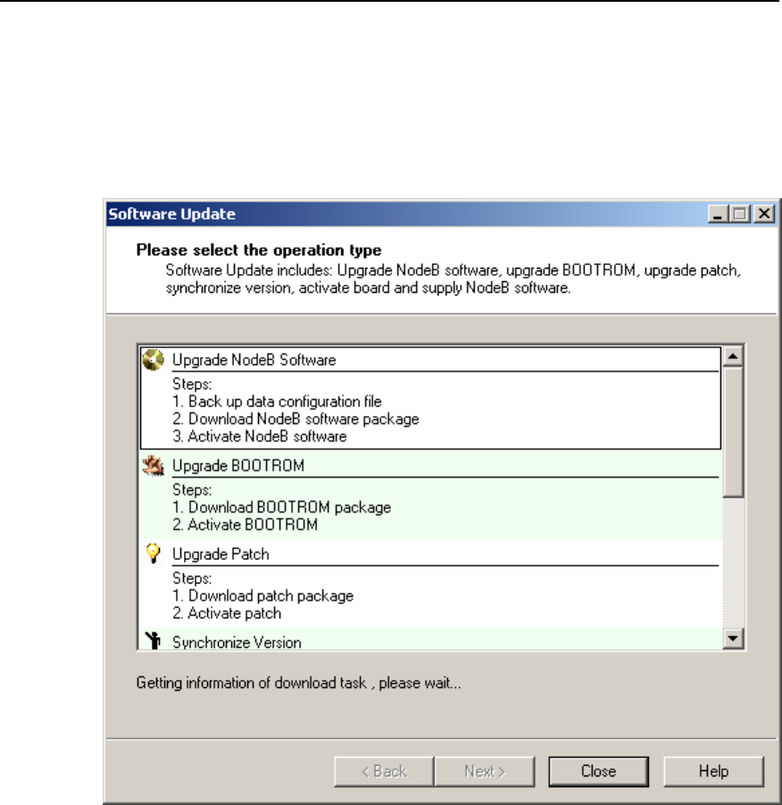
NodeB LMT User Guide
Chapter 14 NodeB Software Update and Data
Configuration File Transfer
Huawei Technologies Proprietary
14-4
III. Procedure
Follow the steps below to download the NodeB software:
1) Choose Maintenance Navigator -> Software Management. Then double-click
the Software Update subnode. The Software Update dialog box opens up as
shown in Figure 14-1.
Figure 14-1 Software Update dialog box
2) Select Upgrade NodeB Software in the dialog box.
3) Click Next.
The Upgrade NodeB Software dialog box opens up as shown in Figure 14-2.
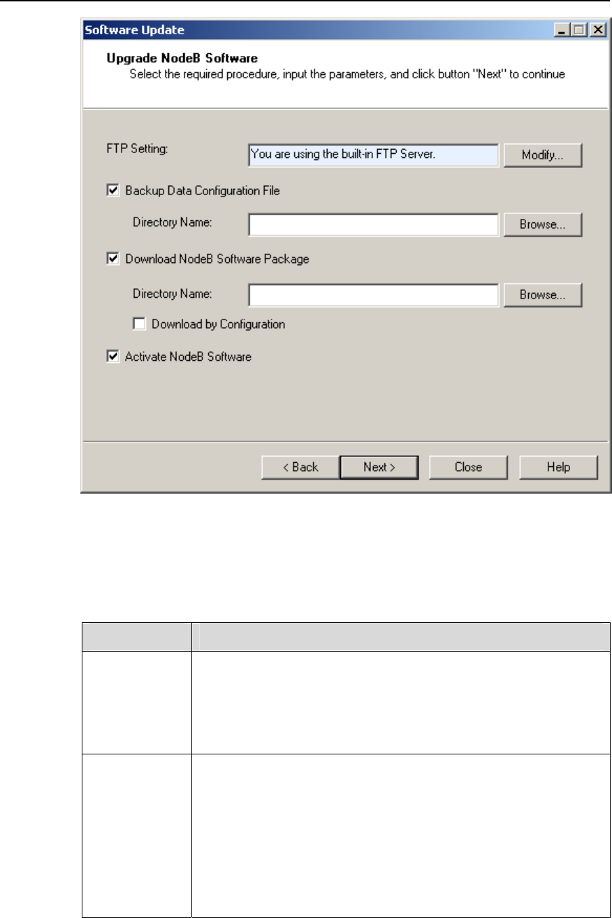
NodeB LMT User Guide
Chapter 14 NodeB Software Update and Data
Configuration File Transfer
Huawei Technologies Proprietary
14-5
Figure 14-2 Upgrade NodeB Software dialog box
Table 14-2 describes the fields of the Upgrade NodeB Software dialog box.
Table 14-2 Field description of Upgrade NodeB Software dialog box
Field Description
FTP Setting
To set the FTP Server for file download
z The FTP Server in use is shown in the box for user’s reference.
The FPT server can be a built-in server or another type of
server specified by user.
z Click Modify… on the right to set the FTP Server.
Backup Data
Configuration
File
To upload the configuration file from the NodeB to the FTP Server
z Click Browse… under Backup Data Configuration File to
specify a directory for the file upload.
z Select it to backup the active configuration file in the system.
z If you have backed up the file, you may skip this step.
z In case of upgrade failure, you can reload the backup
configuration file in the FTP server to guarantee stable
operation of the NodeB.

NodeB LMT User Guide
Chapter 14 NodeB Software Update and Data
Configuration File Transfer
Huawei Technologies Proprietary
14-6
Field Description
Download
NodeB
Software
Package
To download the NodeB software package from the FTP Server to
the NodeB standby directory
z Click Browse… under Download NodeB Software Package.
Select the directory of the package in the FTP Server.
z This operation is mandatory for NodeB software upgrade. The
system will start the download after backing up the
configuration file.
z Because the NodeB software package has a fixed filename of
NodeB.pck, you just need to specify the path of it.
Download by
Configuration
By selecting Download by Configuration, all wanted board
software is downloaded according to the current NodeB
configuration.
Activate
NodeB
Software
To activate NodeB software means to download the unpacked
software package in the NodeB standby area to the target boards,
and then activate the package.
z The NodeB shall be reset after conducting this operation.
z If you select both Download NodeB Software Package and
Activate NodeB Software, the software to be activated is the
NodeB software package downloaded from the FTP Server.
There is no need to select the version.
z If you select Activate NodeB Software without selecting
Download NodeB Software Package, the system will list all
the NodeB software versions that can be activated. Select the
version to activate in the drop-down list.
Note:
z The system performs the above three steps in order: Backup Data Configuration
File, Download NodeB Software Package and then Activate NodeB Software.
z You can choose one or some steps. The system shall proceed with the task
customized by you.
4) Click Modify… in the dialog box. The FTP Settings dialog box opens up as shown
in Figure 14-3.
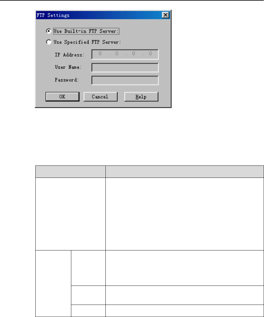
NodeB LMT User Guide
Chapter 14 NodeB Software Update and Data
Configuration File Transfer
Huawei Technologies Proprietary
14-7
Figure 14-3 FTP Settings dialog box
Table 14-3 describes the fields of the FTP Settings dialog box.
Table 14-3 Field description of FTP Settings dialog box
Field Description
Use Built-in FTP Server
z The built-in FTP server of the system is started by
default.
z To stop the FTP server, select System -> Stop FTP
Server.
z To restart the FTP server, select System -> Start FTP
Server.
z Select System -> System Configuration to display
the System Configuration dialog box. Set the user
name and password for the built-in FTP server.
IP
Address
To specify the IP address of the computer hosting the
FTP server
z The FTP Server can be the one started from the LMT
computer or from another computer.
User
Name To specify the user name to log into the FTP Server
Use
Specified
FTP
Server
Password To specify the password to log in to the FTP Server
5) Set parameters in the dialog box.
6) Click OK.
The dialog box is closed and you are presented with the Upgrade NodeB
Software dialog box.
7) Select Backup Data Configuration File to specify a directory for backing up the
file.
Select Download NodeB Software Package to specify a directory for
downloading the NodeB software package.

NodeB LMT User Guide
Chapter 14 NodeB Software Update and Data
Configuration File Transfer
Huawei Technologies Proprietary
14-8
Note:
Backup Data Configuration File is optional.
8) Click Next.
9) Click Yes.
The Upgrading NodeB Software Progress dialog box opens up.
The dialog box indicates the status and progress of the upgrade procedure. You may
check whether the operation is successful.
Note:
The NodeB file directories include
z Active directory: stores the running NodeB software version.
z Standby directory: stores the inactive NodeB software version.
14.3.5 Supplying NodeB Software
I. Introduction
When downloading the NodeB software, you may choose Download by
Configuration in the Upgrade NodeB Software dialog box. If the NodeB configuration
changes by adding a new board, the NodeB shall automatically download the needed
board software with either method below:
z Automatically downloading the needed board software from the download path of
the active NodeB software package
z Automatically downloading the needed board software from the M2000 server
If the automatic download fails, the NodeB reports a Board Version Mismatch alarm
for your manual handling. Then you can supply the NodeB software by downloading the
needed board software.

NodeB LMT User Guide
Chapter 14 NodeB Software Update and Data
Configuration File Transfer
Huawei Technologies Proprietary
14-9
Note:
z After the board software is automatically downloaded, it shall take effect
immediately without being activated.
z After you download the board software manually, the software package is stored in
the NodeB active file directory and shall not take effect immediately. You need to
activate the board software. See 14.3.7 "Activating Board Software".
II. Prerequisites
z There must be the source file path of the software to be downloaded. That is to say,
there must be the NodeB.pck file under the source file path.
z The FTP server works well and is properly connected to the NodeB in the same
Intranet.
z There shall be no firewall between the FTP server and the NodeB.
z The user name and password for the specified FTP server is correct. Ensure you
have the authority to read the data in the specified directory.
III. Procedure
Follow the steps below to supply the NodeB software:
1) Choose Maintenance Navigator -> Software Management. Then double-click
the Software Update subnode.
The Software Update dialog box opens up as shown in Figure 14-1.
2) Select Supply NodeB Software in the dialog box.
3) Click Next.
The Supply NodeB Software dialog box opens up as shown in Figure 14-4.
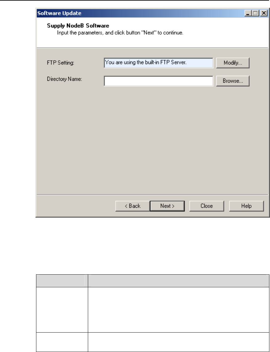
NodeB LMT User Guide
Chapter 14 NodeB Software Update and Data
Configuration File Transfer
Huawei Technologies Proprietary
14-10
Figure 14-4 Supply NodeB Software dialog box
Table 14-4 describes the fields of the Supply NodeB Software dialog box.
Table 14-4 Field description of Supply NodeB Software dialog box
Field Description
FTP Setting
To set the FTP server for the NodeB software download
z The FTP server in use is shown in the box for your reference.
It can be a built-in server or another type of server specified
by you.
z Click Modify… on the right to set the FTP server.
Click Browse… to select the directory of the software package in
the FTP server.
Directory Name
4) Click Modify… in the dialog box.
The FTP Settings dialog box opens up as shown in Figure 14-3.
5) Set parameters in the dialog box.

NodeB LMT User Guide
Chapter 14 NodeB Software Update and Data
Configuration File Transfer
Huawei Technologies Proprietary
14-11
6) Click OK.
The FTP Settings dialog box is closed and you are presented with the Supply
NodeB Software dialog box.
7) Click Browse.
Set the downloading path for the NodeB software package.
8) Click Next.
A dialog box opens up for your confirmation.
9) Click Yes.
The Supplying NodeB Software Progress dialog box opens up.
The status and progress of supplying NodeB software is displayed in the dialog box.
You may check whether the process is completed by viewing this dialog box.
14.3.6 Activating NodeB Software
I. Introduction
The downloaded NodeB software in the standby file directory does not take effect
immediately or damage the running software. You may activate the NodeB software to
make the new software effective.
You may activate a specified NodeB software version during the NodeB operation. In
this way, you can download the software to each board an put it into effect. You may
activate the NodeB software right after the downloading or later on.
II. Prerequisite
None.
III. Procedure
Follow the steps below to activate the NodeB software:
1) Choose Maintenance Navigator -> Software Management. Then double-click
the Software Update subnode.
The Software Update dialog box opens up as shown in Figure 14-1.
2) Select Upgrade NodeB Software in the dialog box.
3) Click Next.
The Upgrade NodeB Software dialog box opens up as shown in Figure 14-2.
4) Select Activate NodeB Software.
Select the NodeB software version to be upgraded in the Version drop-down list
box.
5) Click Next.
A dialog box opens up for your confirmation.

NodeB LMT User Guide
Chapter 14 NodeB Software Update and Data
Configuration File Transfer
Huawei Technologies Proprietary
14-12
Note:
The Version drop-down list box opens up only when you do not select the Download
NodeB Software.
6) Click Yes.
The Software Update Progress dialog box opens up.
The status and progress of the upgrade procedure is displayed in the dialog box. You
may check whether the upgrade is completed by viewing this dialog box.
Note:
14.3.7 If the activation of a board fails, locate the cause and then activate the
software of that board again. See 14.3.7 "Activating Board Software
z The NodeB shall be reset and the new NodeB software version shall be started
upon successful NodeB software activation.
z Reactivate the NodeB software version in the standby file directory or reinstall the
NodeB software upon failure in activation.
14.3.8 Activating Board Software
I. Introduction
To activate the board software is to put a board software version into effect on one
board or a type of boards. The target version of the board software to be activated is the
relevant board software version in the active file directory.
Activate the board software in the following cases:
z A single board of a type of boards fails to be activated in the activation.
z A single board or a type of boards is added or replaced after activating the NodeB
software.
z A single board or a type of boards is loaded with patches.
z The NodeB software has been supplied manually.
II. Prerequisite
None.
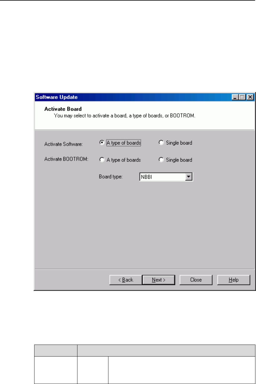
NodeB LMT User Guide
Chapter 14 NodeB Software Update and Data
Configuration File Transfer
Huawei Technologies Proprietary
14-13
III. Procedure
Follow the steps below to activate the NodeB software:
1) Choose Maintenance Navigator -> Software Management. Then double-click
the Software Update subnode.
The Software Update dialog box opens up as shown in Figure 14-1.
2) Select Activate Board in the dialog box.
3) Click Next.
The Activate Board dialog box opens up as shown in Figure 14-5.
Figure 14-5 Activate Board dialog box
Table 14-5 describes the fields of the Activate Board dialog box.
Table 14-5 Field description of Activate Board dialog box
Field Description
Activate
Software
A type of
boards
To activate the software of a type of boards each time
z You need to select the board type from the Board
type drop-down combo box.

NodeB LMT User Guide
Chapter 14 NodeB Software Update and Data
Configuration File Transfer
Huawei Technologies Proprietary
14-14
Field Description
Single
board
To activate the software of one board each time
z You need to set the Subrack No. and Slot No.
according to the board location. For details, see the
equipment panel.
z For the DBS3800, the default value in Slot No. is 0.
A type of
boards
To activate the BOOTROM of a type of boards each
time
z You need to select the board type from the Board
type drop-down combo box.
Activate
BOOTROM
Single
board
To activate the BOOTROM of one board each time
z You need to set Subrack No. and Slot No.
according to the board location. For details, see the
equipment panel.
z For the DBS3800, the default value in Slot No. is 0.
4) Choose A type of boards or Single board on the right of Activate Software.
5) Click Next.
A dialog box opens up for your confirmation.
6) Click Yes.
The Activating Board Progress dialog box opens up.
The status and progress of the board activation is displayed in the dialog box. You may
check whether the process is completed by viewing this dialog box.
14.3.9 Synchronizing Version
I. Introduction
When the new-version NodeB software is proved reliable after trial for a period (three
days recommended, two days at least), you need to synchronize files in the standby
directory with those in the active directory. That is, you need to backup the active
NodeB software version and the BOOTROM software version to the standby directory.
This ensures that the same versions in the standby directory can be activated in case of
failure in the NodeB software version and the BOOTROM software version.
II. Prerequisite
None.
III. Procedure
Follow the steps below to synchronize the software versions:

NodeB LMT User Guide
Chapter 14 NodeB Software Update and Data
Configuration File Transfer
Huawei Technologies Proprietary
14-15
1) Choose Maintenance Navigator -> Software Management. Then double-click
the Software Update subnode.
The Software Update dialog box opens up as shown in Figure 14-1.
2) Select Synchronize Version in the dialog box.
3) Click Next.
The Synchronize Version dialog box opens up.
4) If the synchronization status is Synchronizing or Synchronized, it indicates the
NodeB software version is synchronizing or has been synchronized. The
operation is complete.
5) If the synchronization status is Not Synchronized, click Next in the dialog box.
A dialog box opens up for you confirmation.
6) Click Yes.
The Synchronization Version Progress dialog box opens up.
7) The status and progress of synchronization is displayed in the dialog box.
8) Click Close.
The synchronization process is stopped when the synchronization is complete.
14.4 Upgrading NodeB BOOTROM
14.4.1 Overview
To upgrade the NodeB BOOTROM is to upgrade all the BOOTROM software of each
board on the NodeB.
14.4.2 Introduction to BOOTROM Software
A BOOTROM is a writable and erasable storage medium for binary data (machine
code). The BOOTROM software refers to the software bound with hardware. It provides
basic device drive function and can be started and updated manually.
All the boards on the NodeB have the BOOTROM software. For a macro NodeB, the
NAOI and the NDTI both are equipped with BOOTROMs that are located in the master
CPU and the slave CPU.
The BOOTROM software is a compressed file with the fixed filename of NodeB.pck.
14.4.3 Procedure of Upgrading NodeB BOOTROM Software
Table 14-6 describes how to upgrade the NodeB BOOTROM software.

NodeB LMT User Guide
Chapter 14 NodeB Software Update and Data
Configuration File Transfer
Huawei Technologies Proprietary
14-16
Table 14-6 Procedure of upgrading NodeB BOOTROM
Step Procedure Description Reference
1
Download NodeB
BOOTROM
package
To download the new
software version for
upgrade
See 14.4.4
"Downloading NodeB
BOOTROM Package"
2 Activate NodeB
BOOTROM
To activate all the boards
on the NodeB
See 14.4.5 "Activating
NodeB BOOTROM"
3 Activate board
BOOTROM
To activate the board
failing to be activated in
the previous step by
viewing details
See 14.4.6 "Activating
Board BOOTROM"
Note:
z The BOOTROM version shall be automatically refreshed after the NodeB
BOOTROM upgrade. Then you may check whether the upgrade is successful by
viewing the NodeB version and the board version.
z Step 1) and step 2) are integrated into one. You can perform the two steps in one
process.
z The NodeB shall not be reset due to upgrading the NodeB BOOTROM. The
BOOTROM software does not affect the NodeB services. Therefore, there is no
need to reset the NodeB or board to make the BOOTROM software effective after
the upgrade. The NodeB starts with the upgraded BOOTROM during next reset.
14.4.4 Downloading NodeB BOOTROM Package
I. Introduction
To download the NodeB BOOTROM package is to download the NodeB BOOTROM
software package from the FTP server to the NodeB standby file directory.
II. Prerequisites
z The FTP server works well and is properly connected to the NodeB in the same
Intranet.
z There shall be no firewall between the FTP server and the NodeB.
z The user name and password for the specified FTP server is correct. Ensure you
have the authority to read the data in the specified directory.
III. Procedure
Follow the steps below to download the NodeB BOOTROM software package:
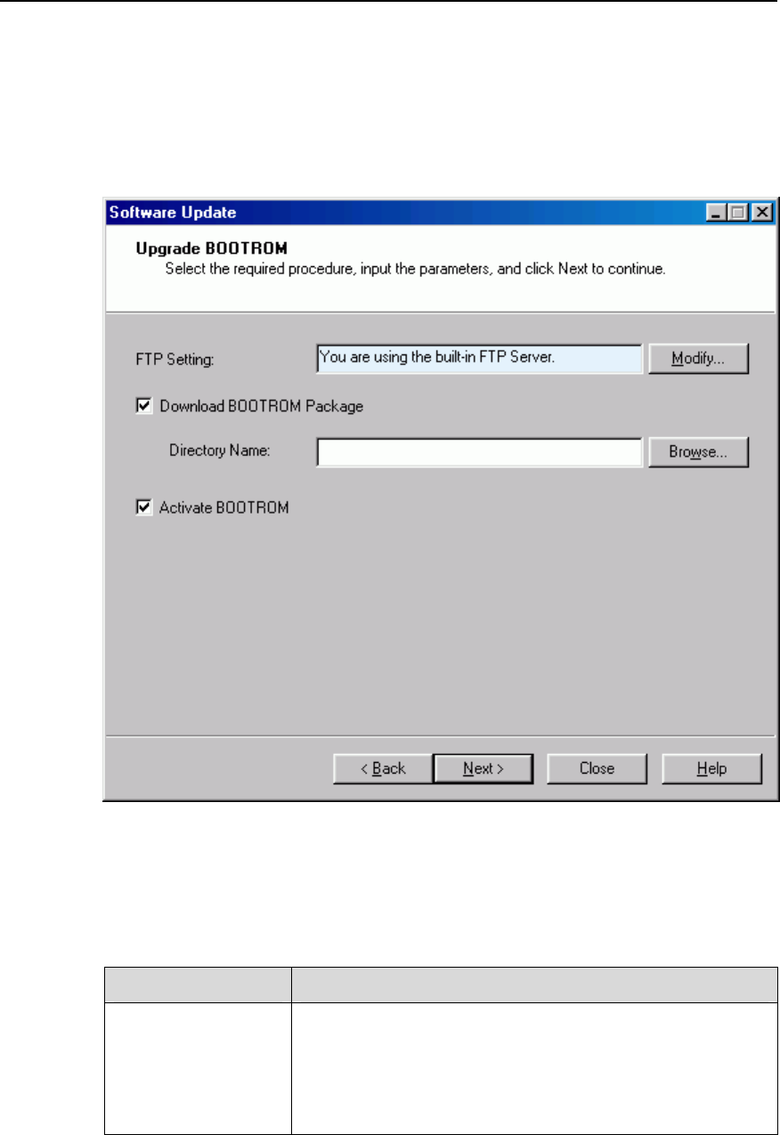
NodeB LMT User Guide
Chapter 14 NodeB Software Update and Data
Configuration File Transfer
Huawei Technologies Proprietary
14-17
1) Choose Maintenance Navigator -> Software Management. Then double-click
the Software Update subnode.
The Software Update dialog box opens up as shown in Figure 14-1.
2) Select Upgrade BOOTROM in the dialog box.
3) Click Next.
The Upgrade BOOTROM dialog box opens up as shown in Figure 14-6.
Figure 14-6 Upgrade BOOTROM dialog box
Table 14-7 describes the fields of the Upgrade BOOTROM dialog box.
Table 14-7 Field description of Upgrade BOOTROM dialog box
Filed Description
FTP Setting
To set the FTP server for file upload and download
z The FTP server in use is shown in the box for your
reference. The FPT server can be a built-in server or
another type of server specified by you.
z Click Modify… on the right to set the FTP Server.

NodeB LMT User Guide
Chapter 14 NodeB Software Update and Data
Configuration File Transfer
Huawei Technologies Proprietary
14-18
Filed Description
Download
BOOTROM Package
To download the NodeB BOOTROM package from the FTP
server to the NodeB standby file directory
z Click Browse… to select the directory of the BOOTROM
software package in the FTP server.
z Select it to download the NodeB BOOTROM package.
This operation is mandatory for upgrading the NodeB
BOOTROM package.
z Because the NodeB BOOTROM package has a fixed
filename NbRom.pck, you just need to specify the path
of it.
Activate BOOTROM
To activate the NodeB BOOTROM right after downloading
the NodeB BOOTROM package by selecting this box.
z If you select both Download BOOTROM Package and
Activate BOOTROM, the BOOTROM to be activated is
the NodeB BOOTROM package downloaded from the
FTP Server. There is no need to select the version.
z If you select Activate BOOTROM without selecting
Download BOOTROM Package, the system shall list all
the NodeB BOOTROM versions that can be activated.
Select the NodeB BOOTROM version to be upgraded in
the Version drop-down box.
Note:
z The system downloads the NodeB BOOTROM package first and then activates it.
z You may choose to perform either step. In that case, the system shall skip the other
step.
4) Click Modify… in the dialog box.
The FTP Settings dialog box opens up as shown in Figure 14-3.
5) Set parameters in the dialog box.
6) Click OK.
The FTP Settings dialog box is closed and you are presented with the Upgrade
BOOTROM dialog box.
7) Select Download BOOTROM Package.
Specify a directory to download the BOOTROM package.
8) Click Next.
A dialog box opens up for your confirmation.
9) Click Yes.
The Upgrading BOOTROM Progress dialog box opens up.
You may check whether the process is completed by viewing this dialog box.

NodeB LMT User Guide
Chapter 14 NodeB Software Update and Data
Configuration File Transfer
Huawei Technologies Proprietary
14-19
14.4.5 Activating NodeB BOOTROM
I. Introduction
To activate the NodeB BOOTROM is to download the BOOTROM in the NodeB
standby file directory to each board and upgrade the board BOOTROM.
Before the activation, the system checks the BOOTROM versions of the boards. It
activates the board BOOTROM only when there is a new BOOTROM version.
II. Prerequisite
None.
III. Procedure
Follow the steps below to activate the NodeB BOOTROM:
1) Choose Maintenance Navigator -> Software Management. Then double-click
the Software Update subnode.
The Software Update dialog box opens up as shown in Figure 14-1.
2) Select Upgrade BOOTROM in the dialog box.
3) Click Next.
The Upgrade BOOTROM dialog box opens up as shown in Figure 14-6.
4) Select Activate NodeB Software in the dialog box. Select the NodeB BOOTROM
software version to be upgraded in the Version drop-down list box.
5) Click Next.
A dialog box opens up for your confirmation.
6) Click Yes.
The Upgrading BOOTROM Progress dialog box opens up.
The status and progress of upgrading BOOTROM is displayed in the dialog box. You
may check whether the process is completed by viewing this dialog box.

NodeB LMT User Guide
Chapter 14 NodeB Software Update and Data
Configuration File Transfer
Huawei Technologies Proprietary
14-20
Note:
14.4.6 If the BOOTROM activation of a board fails, locate the cause and then
activate the BOOTROM software of that board again. See 14.4.6 "Activating
Board BOOTROM
z Because the BOOTROM software does not affect the NodeB services, there is no
need to reset the NodeB to make the NodeB BOOTROM effective. The NodeB
starts with the upgraded BOOTROM during next reset.
z The NodeB BOOTROM activation does not lead to NodeB reset.
14.4.7 Activating Board BOOTROM
I. Introduction
To activate the board BOOTROM software is to activate the BOOTROM software of a
single board or a type of boards.
Activate the board BOOTROM software in the following cases:
z The BOOTROM of a single board or a type of boards fails to be activated in the
NodeB BOOTROM activation.
z The BOOTROM of a single board or a type of board needs to be upgraded.
II. Prerequisite
None.
III. Procedure
Follow the steps below to activate the board BOOTROM:
1) Choose Maintenance Navigator -> Software Management. Then double-click
the Software Update subnode.
The Software Update dialog box opens up as shown in Figure 14-1.
2) Select Activate Board in the dialog box.
3) Click Next.
The Activate Board dialog box opens up as shown in Figure 14-5.
4) Choose A type of boards or Single board on the right of Activate BOOTROM.
5) Click Next.
A dialog box opens up for your confirmation.
6) Click Yes.
The Activating Board Progress dialog box opens up.

NodeB LMT User Guide
Chapter 14 NodeB Software Update and Data
Configuration File Transfer
Huawei Technologies Proprietary
14-21
The status and progress of the board BOOTROM activation is displayed in the dialog
box. You may check whether the process is completed by viewing this dialog box.
14.5 Upgrading Patches
14.5.1 Overview
To upgrade a patch is to upgrade a specified board or module on the NodeB for the
purpose of perfecting a function or clearing a defect.
14.5.2 Introduction to Patch
A patch is a compressed file with a fixed filename of NodeB.pck.
14.5.3 Procedure of Upgrading Patches
Table 14-8 describes how to upgrade a patch.
Table 14-8 Procedure of upgrading a patch
Step Procedure Description Reference
1 Download patch
package
To download the new patch
for upgrade
14.5.4
"Downloading Patch
Package
2 Activate patch
package
To activate the patches to
upgrade the board or module
14.5.5 "Activating
Patches"
3
Reactivate patch
for the board failing
to be activated
To reactivate the board failing
to be activated by viewing the
detailed list.
14.5.5 "Activating
Patches"
Note:
z Step 1) and step 2) are integrated into one. You can perform the two in one step.
z Patch upgrade leads to reset of the related board. Therefore, services on that board
shall be interrupted.
z You may check whether the upgrade is successful by viewing the upgraded patch
version.

NodeB LMT User Guide
Chapter 14 NodeB Software Update and Data
Configuration File Transfer
Huawei Technologies Proprietary
14-22
14.5.4 Downloading Patch Package
I. Introduction
To download the patch is to download the patch package from the FTP server to the
NodeB standby file directory.
II. Prerequisites
z The FTP server works well and is properly connected to the NodeB in the same
Intranet.
z There shall be no firewall between the FTP server and the NodeB.
z The user name and password for the specified FTP server is correct. Ensure you
have the authority to read the data in the specified directory.
III. Procedure
Follow the steps below to download the patch package:
1) Choose Maintenance Navigator -> Software Management. Then double-click
the Software Update subnode.
The Software Update dialog box opens up as shown in Figure 14-1.
2) Select Upgrade Patch in the dialog box.
3) Click Next.
The Upgrade Patch dialog box opens up as shown in Figure 14-7.
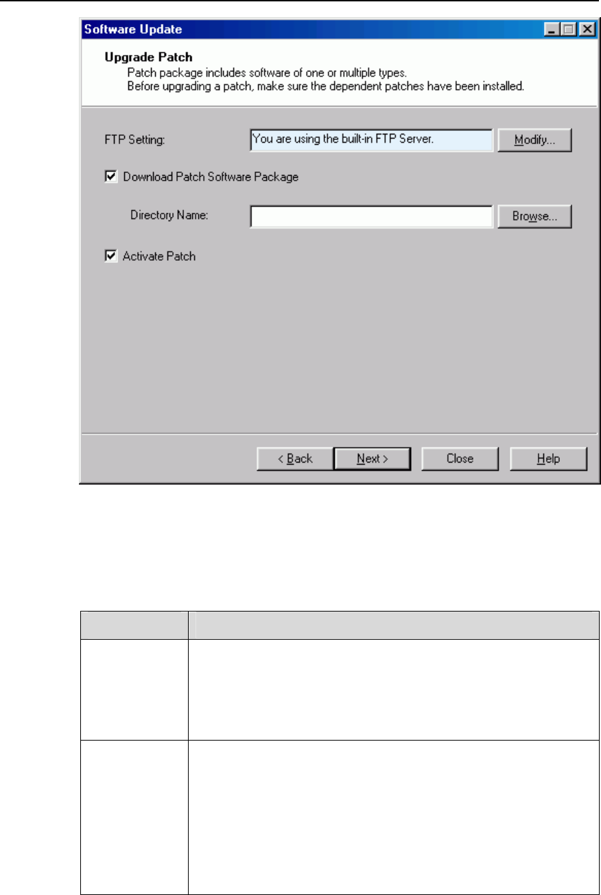
NodeB LMT User Guide
Chapter 14 NodeB Software Update and Data
Configuration File Transfer
Huawei Technologies Proprietary
14-23
Figure 14-7 Upgrade Patch dialog box
Table 14-9 describes the fields of the Upgrade Patch dialog box.
Table 14-9 Field description of Upgrade Patch dialog box
Field Description
FTP Setting
To set the FTP server for downloading the patch
z The FTP server in use is shown in the box for your reference. It
can be a built-in server or another type of server specified by
you.
z Click Modify… on the right to set the FTP server.
Download
Patch Software
Package
To download the patch package from the FTP server to the NodeB
standby file directory
z Click Browse… to select the directory of the package in the
FTP server.
z Select it to download the NodeB BOOTROM package. This
operation is mandatory for patch upgrade.
z Because the patch package has a fixed filename
NbPatch.pck, you just need to specify the path of it.
NodeB LMT User Guide
Chapter 14 NodeB Software Update and Data
Configuration File Transfer
Huawei Technologies Proprietary
14-24
Field Description
Activate Patch To activate the patch right after downloading the patch package
by choosing this box.
Note:
z The system downloads the patch package first and then activates it.
z You may choose to perform either step. In that case, the system shall skip the other
step.
4) Click Modify… in the dialog box.
The FTP Settings dialog box opens up as shown in Figure 14-3.
5) Set parameters in the dialog box.
6) Click OK.
The FTP Settings dialog box is closed and you are presented with the Upgrade
Patch dialog box.
7) Select Download Patch Software Package. Specify a directory to download the
patch package.
8) Click Next.
A dialog box opens up for your confirmation.
9) Click Yes.
The Upgrading Patch Progress dialog box opens up.
The status and progress of upgrading patch is displayed in the dialog box. You may
check whether the process is completed by viewing this dialog box.
14.5.5 Activating Patches
I. Introduction
To activate a patch is to download the patch in the NodeB standby file directory to the
target board and then upgrade the patch release of that board.
II. Prerequisite
None.
III. Procedure
Follow the steps below to activate a patch:

NodeB LMT User Guide
Chapter 14 NodeB Software Update and Data
Configuration File Transfer
Huawei Technologies Proprietary
14-25
1) Choose Maintenance Navigator -> Software Management. Then double-click
the Software Update subnode.
The Software Update dialog box opens up as shown in Figure 14-1.
2) Select Upgrade Patch in the dialog box.
3) Click Next.
The Upgrade Patch dialog box opens up as shown in Figure 14-7.
4) Select Activate Patch in the dialog box.
5) Click Next.
A dialog box opens up for your confirmation.
6) Click Yes.
The Upgrading Patch Progress dialog box opens up.
The status and progress of upgrading patch is displayed in the dialog box. You may
check whether the process is completed by viewing this dialog box.
Note:
z If the activation of a board fails, locate the cause and then activate the patch release
of that board again.
z Patch upgrade leads to reset of the related board. Therefore, services on that board
shall be interrupted.
14.6 Downloading Data Configuration File
14.6.1 Introduction Data Configuration File
The data configuration file records the settings of each NodeB module. It has a fixed
filename of NodeBCfg.xml.
You may upload or download the data configuration file.
14.6.2 Downloading Data Configuration File
I. Introduction
To download a data configuration file is to download a data configuration file from the
FTP server to the NodeB. The new data configuration file takes effect after resetting the
NodeB.
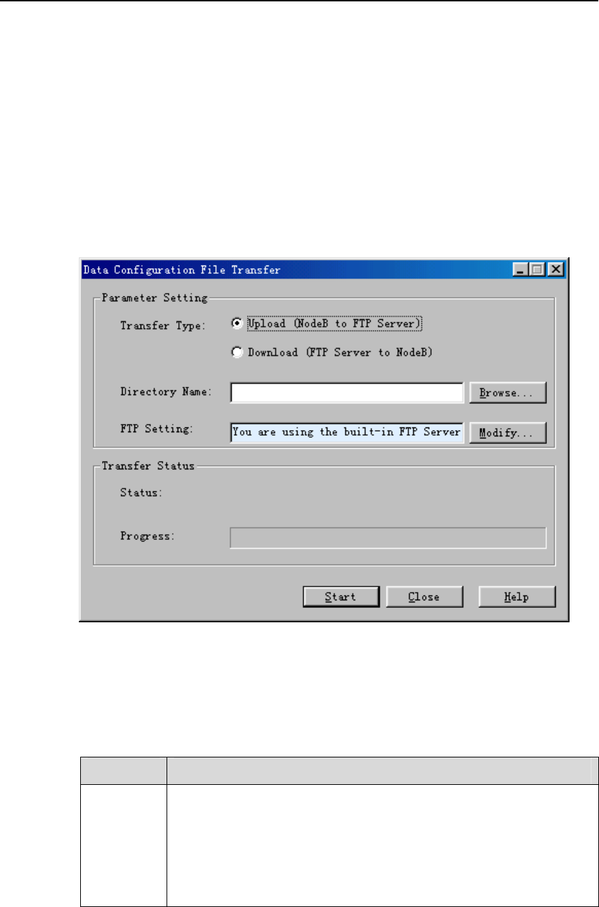
NodeB LMT User Guide
Chapter 14 NodeB Software Update and Data
Configuration File Transfer
Huawei Technologies Proprietary
14-26
II. Prerequisite
None.
III. Procedure
Follow the steps below to download the data configuration file:
1) Choose Maintenance Navigator -> Software Management. Then double-click
the Data Configuration File Transfer subnode.
The Data Configuration File Transfer dialog box opens up as shown in Figure
14-8.
Figure 14-8 Data Configuration File Transfer dialog box
Table 14-10 describes the fields of the Data Configuration File Transfer dialog box.
Table 14-10 Field description of Data Configuration File Transfer dialog box
Field Description
Transfer
Type
z Upload (NodeB to FTP Server): The system uploads the
configuration file of NodeBCfg.xml from the NodeB to the FTP
Server for viewing, modifying and saving.
z Download (FTP Server to NodeB): The system downloads the
configuration file of NodeBCfg.xml from the FTP Server to the
NodeB. The configuration file of the latest version takes effect after
resetting the NodeB.

NodeB LMT User Guide
Chapter 14 NodeB Software Update and Data
Configuration File Transfer
Huawei Technologies Proprietary
14-27
Directory
Name
To specify the directory for the configuration file in the FTP Server
z The configuration file has a fixed filename. Therefore, the system
can identify it in the directory.
z If you select Upload (NodeB to FTP Server), it is the destination
path.
z If you select Download (FTP Server to NodeB), it is the source
path.
FTP
Setting
To set the FTP Server for file upload and download
z The FTP Server in use is shown in the box for your reference.
z Click Modify… on the right to set the FTP Server.
2) Click Modify… in the dialog box.
The FTP Settings dialog box opens up as shown in Figure 14-3.
3) Set parameters in the dialog box. See section 6.3.1 "Uploading Operation Log
File".
4) Click OK.
The FTP Settings dialog box is closed and you are presented with the Data
Configuration File Transfer dialog box.
5) Select Download (FTP Server to NodeB) after Transfer Type.
6) Set other parameters in the dialog box.
7) Click Start.
The system starts to download the data configuration file.
Note:
You can also download the data configuration file by the MML command of DLD
CFGFILE.
14.6.3 Backing up Data Configuration File
I. Introduction
To backup a data configuration file is to upload a data configuration file from the NodeB
to the FTP server for saving and viewing.
II. Prerequisite
None.

NodeB LMT User Guide
Chapter 14 NodeB Software Update and Data
Configuration File Transfer
Huawei Technologies Proprietary
14-28
III. Procedure
The procedure of backing up the data configuration file is almost the same as that of
downloading the data configuration file. The only difference lies in step 5) that you need
to select Upload (NodeB to FTP Server) after Transfer Type. See 14.6.2
"Downloading Data Configuration File".
Note:
You can also backup the data configuration file by the MML command of ULD
CFGFILE.


NodeB LMT User Guide Appendix A Acronyms and Abbreviations
Appendix A Acronyms and Abbreviations
A
ALCAP Access Link Control Application Part
AMI Alternate Mark Inversion
ATM Asynchronous Transfer Mode
B
BCH Broadcast Channel
BER Basic Encoding Rules
BIP Bit Interleaved Parity
BITS Building Integrated Timing Supply
BLER Block Error Rate
C
CES Circuit Emulation Service
CPICH Common Pilot Channel
CPU Center Processing Unit
CRC Cyclic Redundancy Check
D
DPCH Dedicated Physical Channel
DSP Digital Signal Processor
F
FEBE Far End Bit Error
FP Frame protocol
FTP File Transfer Protocol
G
GPS Global Position System
GUI Graphic User Interface
H
HBBI NodeB HSDPA Baseband processing and Interface unit
HBOI NodeB HSDPA Baseband processing and Optical Interface
unit
HEC Header Error Control
HDLP NodeB HSDPA supported Down Link Processing Unit
Huawei Technologies Proprietary
A-1

NodeB LMT User Guide Appendix A Acronyms and Abbreviations
HULP NodeB HSDPA supported Uplink Processing Unit
I
ID Identity
IUB Iub Interface
L
LMT Local Maintenance Terminal
M
MAFU Multicarrier Antenna Filter Unit
MML Human-Machine Language (formerly Man-Machine Language)
MTRU NodeB Multi-carrier TRansceiver Unit
N
NAOI NodeB ATM Optical Interface unit
NBAP NodeB Application Part
NBBI NodeB Baseband processing and Interface unit
NCCU NodeB Cable Connected Unit
NDTI NodeB Digital Trunk Interface unit
NFAN NodeB FAN box
NMON NodeB Monitor unit
NMPT NodeB Main Processor & Timing unit
O
OCXO Oven Controlled Crystal Oscillator
OTSR Omi-directional Transmit Sector Receive
P
PCCPCH Primary Common Control Physical Channel
PHS Packet Handling Switching
PMU Power and Environment Monitoring unit
PSU Power Supply Unit
R
RACH Random Access Channel
RMS Root Mean Square
RNC Radio Network Controller
RRU Radio Remote Unit
RTWP Received Total Wideband Power
S
Huawei Technologies Proprietary
A-2

NodeB LMT User Guide Appendix A Acronyms and Abbreviations
SDH Synchronous Digital Hierarchy
T
TPC Transmission power control
U
UE User Equipment
UMTS Universal Mobile Telecommunications System
UTOPIA Universal Test & Operations PHY Interface for ATM
UTRA UMTS Terrestrial radio access (ETSI)
UTRAN UMTS Terrestrial Radio Access Network
W
WCDMA Wideband Code Division Multiple Access
Huawei Technologies Proprietary
A-3