Huawei Technologies RRU3804B2 Distributed NodeB Remote Radio Unit User Manual User Guide
Huawei Technologies Co.,Ltd Distributed NodeB Remote Radio Unit User Guide
UserManual.wiki
>
Huawei Technologies
>
RRU3804B2 User Manual
User Manual
Navigation menu
Upload a User Manual
Namespaces
Wiki Guide
HTML
PDF
Info
Views
User Manual
Discussion / Help
Navigation


![Convention Description[ ] Items (keywords or arguments) in square brackets [ ] are optional.{x | y | ...} Alternative items are grouped in braces and separated by verticalbars.One is selected.[ x | y | ... ] Optional alternative items are grouped in square brackets andseparated by vertical bars.One or none is selected.{ x | y | ... } * Alternative items are grouped in braces and separated by verticalbars.A minimum of one or a maximum of all can be selected.[ x | y | ... ] * Alternative items are grouped in braces and separated by verticalbars.A minimum of zero or a maximum of all can be selected.4. GUI ConventionsConvention DescriptionBoldface Buttons,menus,parameters,tabs,window,and dialog titles are inboldface. For example,click OK.>Multi-level menus are in boldface and separated by the ">" signs.For example,choose File > Create > Folder .5. Keyboard OperationConvention DescriptionKey Press the key.For example,press Enter and press Tab.Key1+Key2 Press the keys concurrently.For example,pressing Ctrl+Alt+Ameans the three keys should be pressed concurrently.Key1,Key2 Press the keys in turn.For example,pressing Alt,A means the twokeys should be pressed in turn.6. Mouse OperationAction DescriptionClick Select and release the primary mouse button without moving thepointer.Double-click Press the primary mouse button twice continuously and quicklywithout moving the pointer.Drag Press and hold the primary mouse button and move the pointerto a certain position.RRUUser Guide About This DocumentIssue 01 (2008-04-18) Huawei Proprietary and ConfidentialCopyright © Huawei Technologies Co., Ltd3](https://usermanual.wiki/Huawei-Technologies/RRU3804B2/User-Guide-980104-Page-17.png)
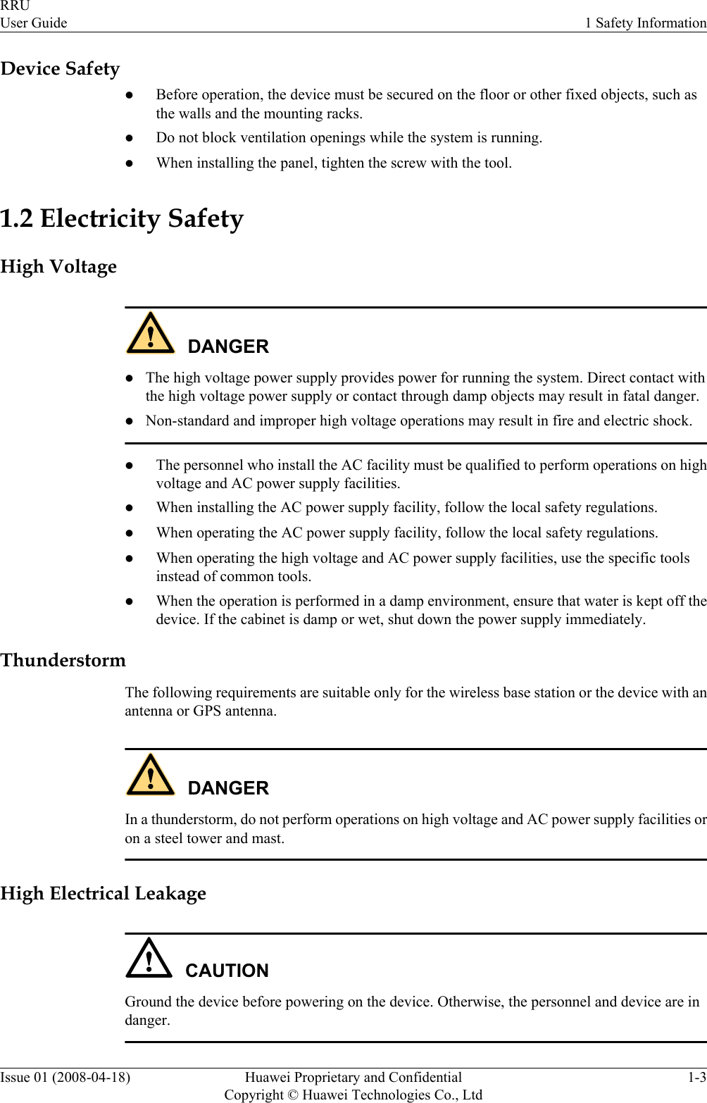


![lIf the areas where RF radiation exceeds the stipulated value are accessible to workers,ensure that workers know where these areas are. They can shut down the transmitters beforeentering these areas. Such areas may not exist; but if they exist, the areas must be within arange of less than 10 m around the antennas.lEach forbidden zone should be indicated by a physical barrier and striking sign to warn thepublic or workers.LaserCAUTIONWhen handling optical fibers, do not stand close to, or look into the optical fiber outlet withunaided eyes.Laser transceivers or transmitters are used in the optical transmission system and associated testtools. Because the laser that is transmitted through the optical fiber produces a small beam oflight, it has a very high power density and is invisible to human eyes. If a beam of light entersthe eye, the retina may be damaged.Normally, staring into the end of an unterminated optical fiber or broken optical fiber with theunaided eyes from a distance of more than 150 mm [5.91 in.] will not cause eye injury. Eyesmay, however, be damaged if an optical tool such as a microscope, magnifying glass or eyeloupe is used to stare into the bare optical fiber end.Read the following guidelines to prevent laser radiation:lOnly the trained and authorized personnel can perform the operation.lWear a pair of eye-protective glasses when you are handling lasers or optical fibers.lEnsure that the optical source is switched off before disconnecting optical fiber connectors.lNever look into the end of an exposed optical fiber or an open connector if you cannotensure that the optical source is switched off.lTo ensure that the optical source is switched off, use an optical power meter.lBefore opening the front door of an optical transmission system, ensure that you are notexposed to laser radiation.lNever use an optical tool such as a microscope, a magnifying glass, or an eye loupe to lookinto the optical fiber connector or end.Read the following instructions before handling optical fibers:lOnly the trained personnel can cut and splice optical fibers.lBefore cutting or splicing an optical fiber, ensure that the optical fiber is disconnected fromthe optical source. After disconnecting the optical fiber, use protecting caps to protect allthe optical connectors.1 Safety InformationRRUUser Guide1-8 Huawei Proprietary and ConfidentialCopyright © Huawei Technologies Co., LtdIssue 01 (2008-04-18)](https://usermanual.wiki/Huawei-Technologies/RRU3804B2/User-Guide-980104-Page-26.png)