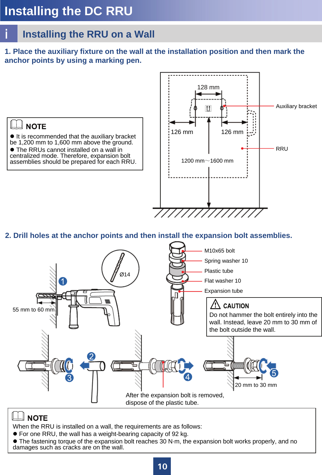
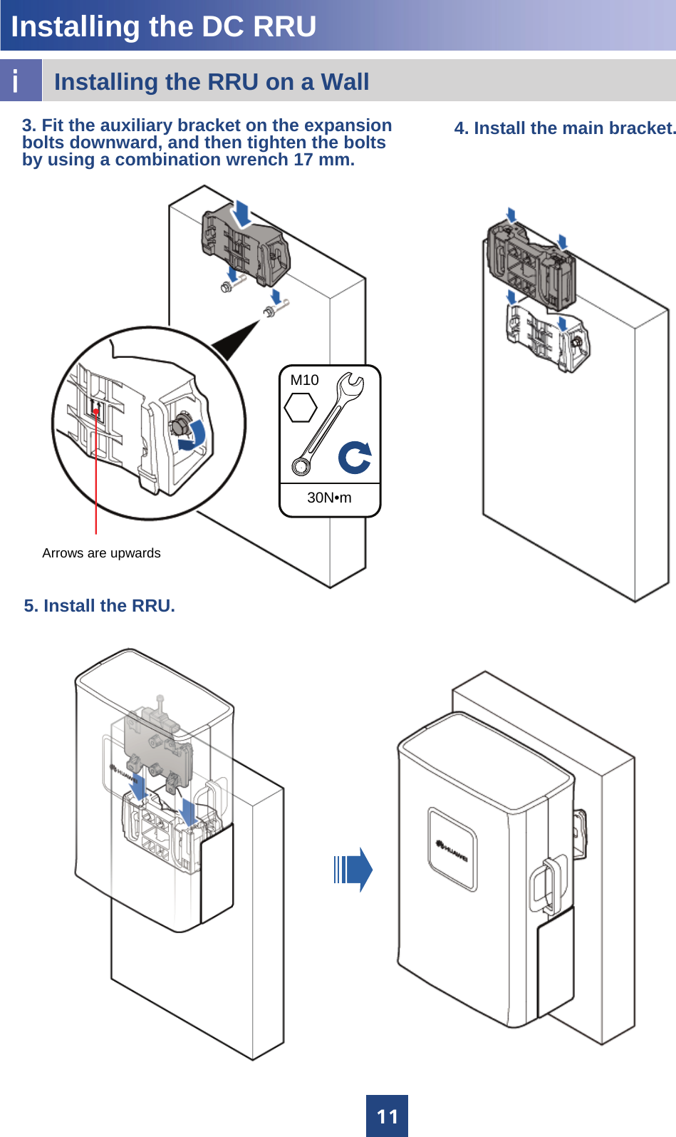
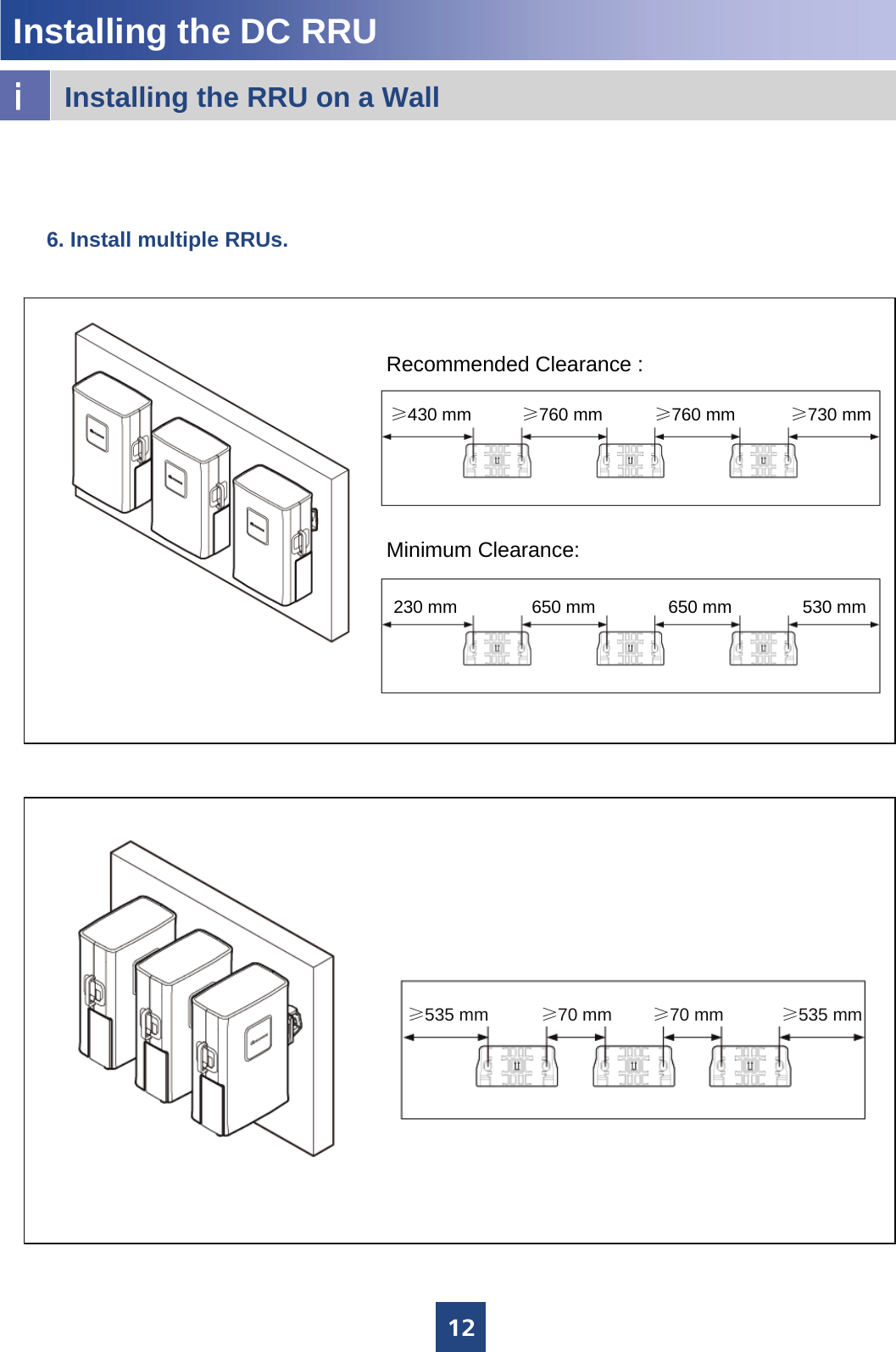
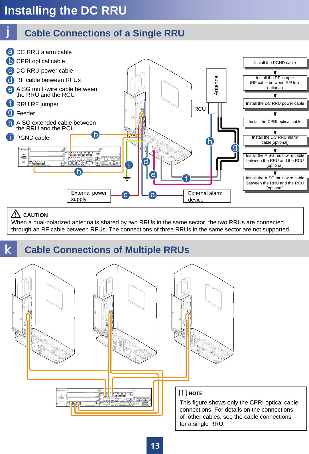
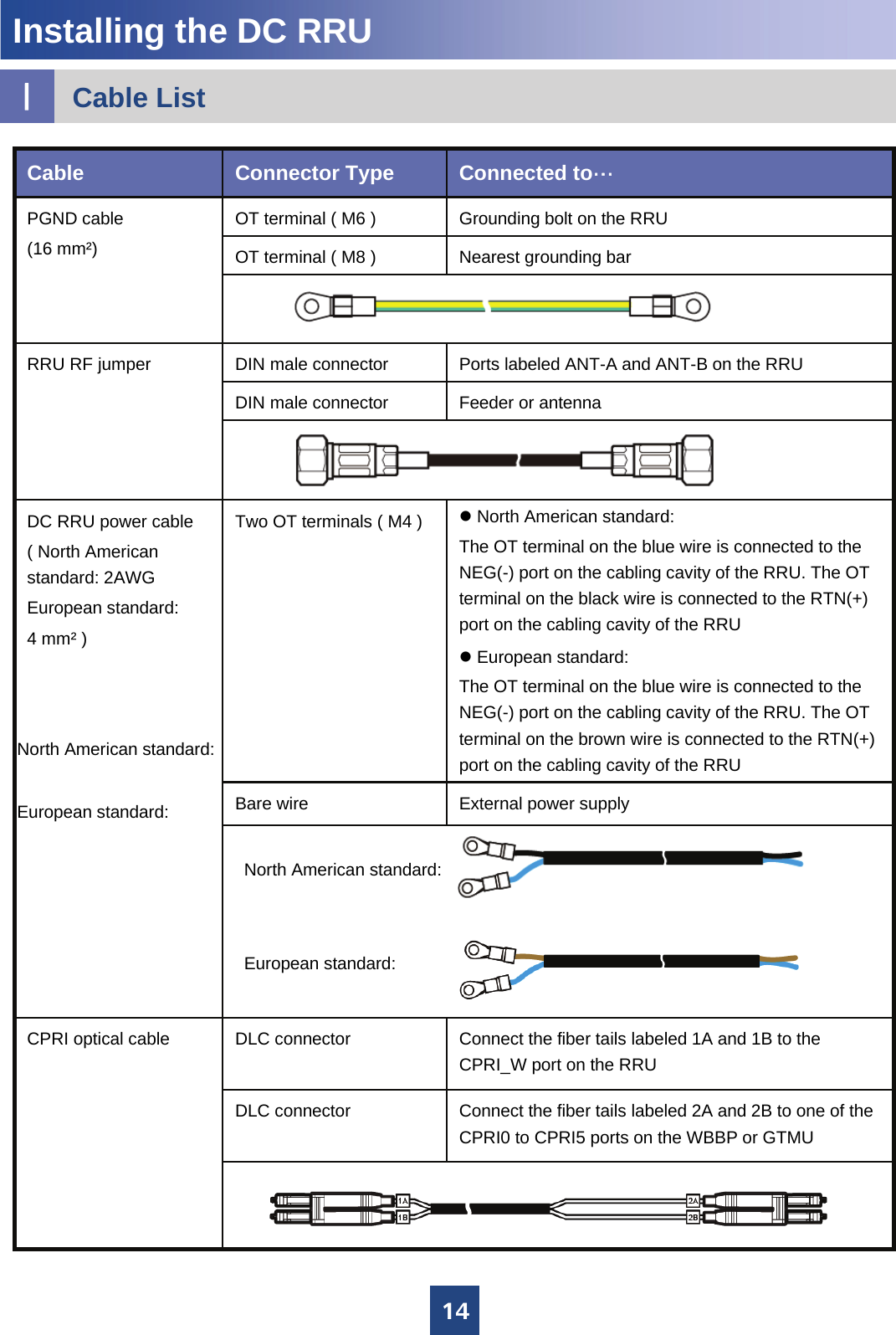
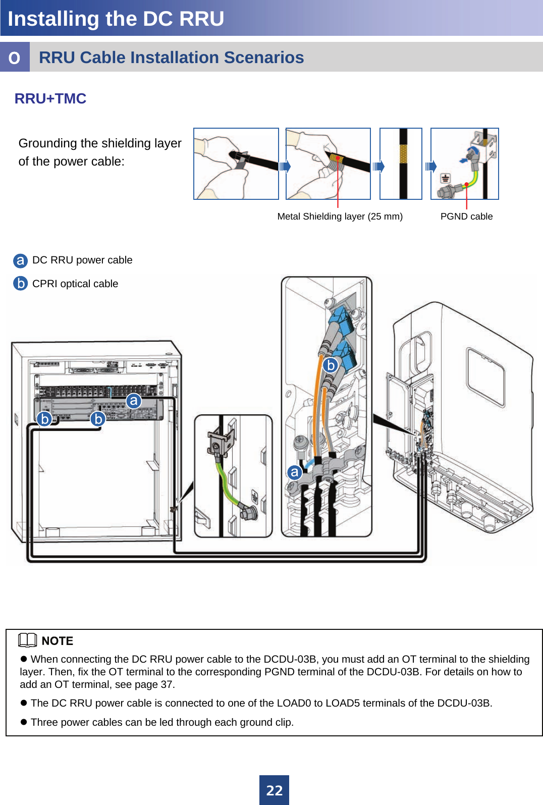
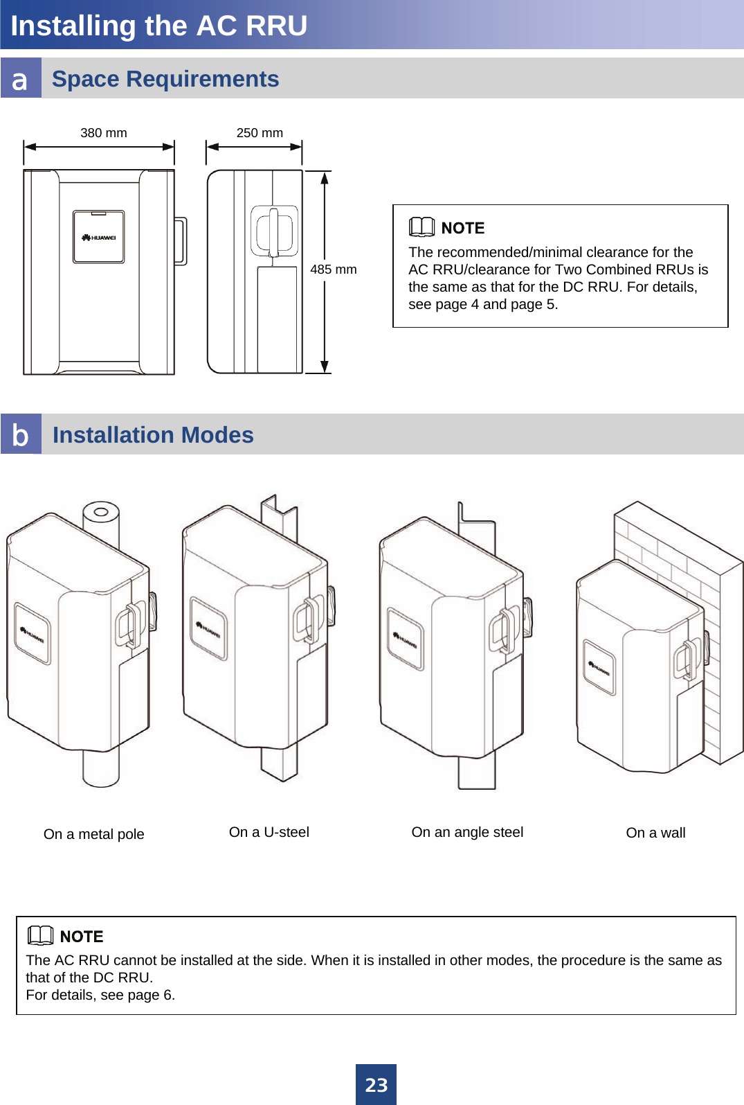
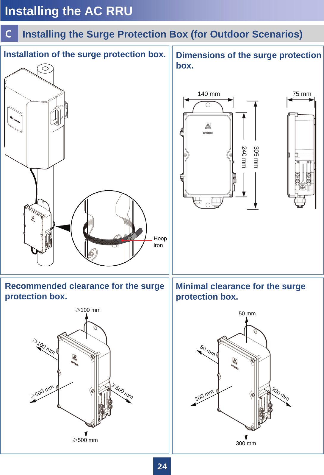
Huawei Technologies RRU3908-1900 Remote Radio Unit of Multi-Mode Distributed Base Station User Manual RRU3908 V1 Installation Guide

Huawei Technologies Co.,Ltd Remote Radio Unit of Multi-Mode Distributed Base Station RRU3908 V1 Installation Guide
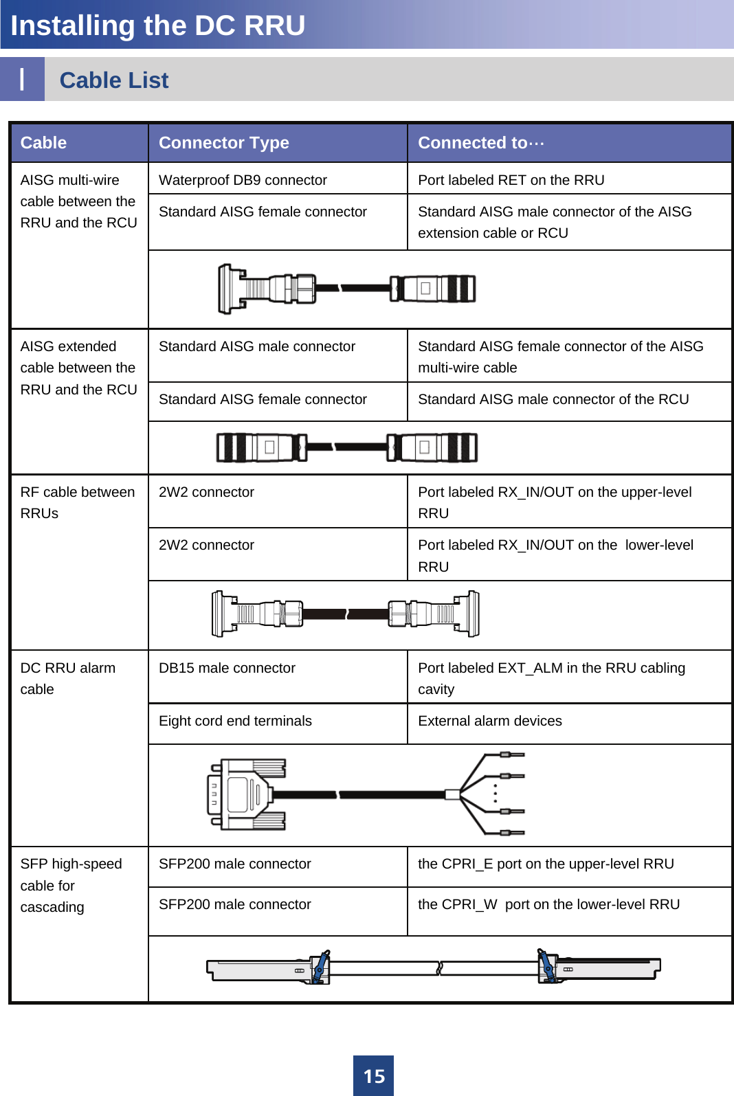
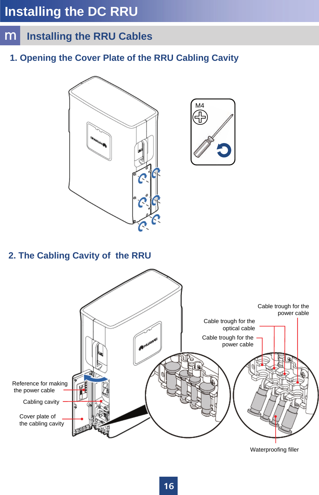
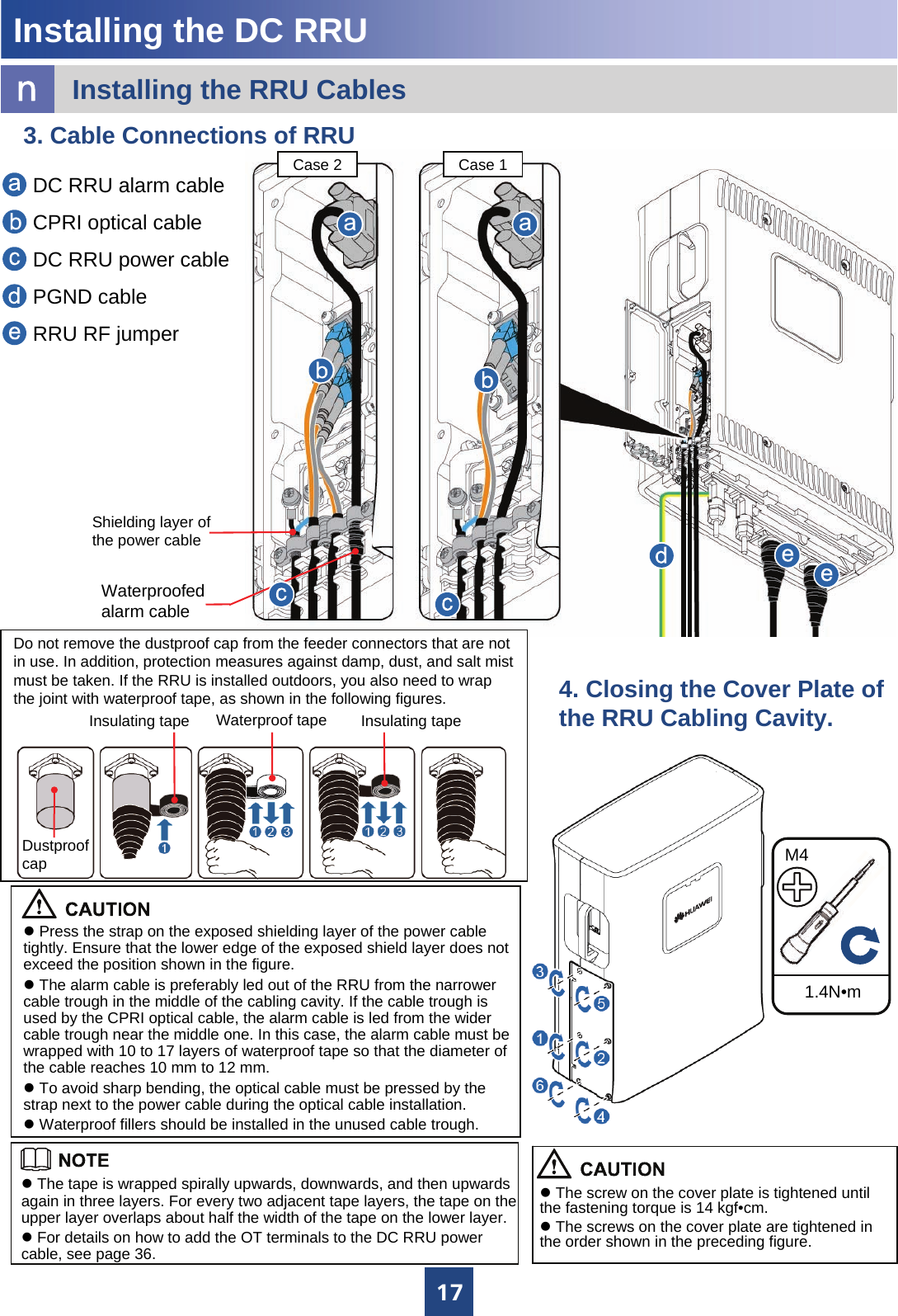
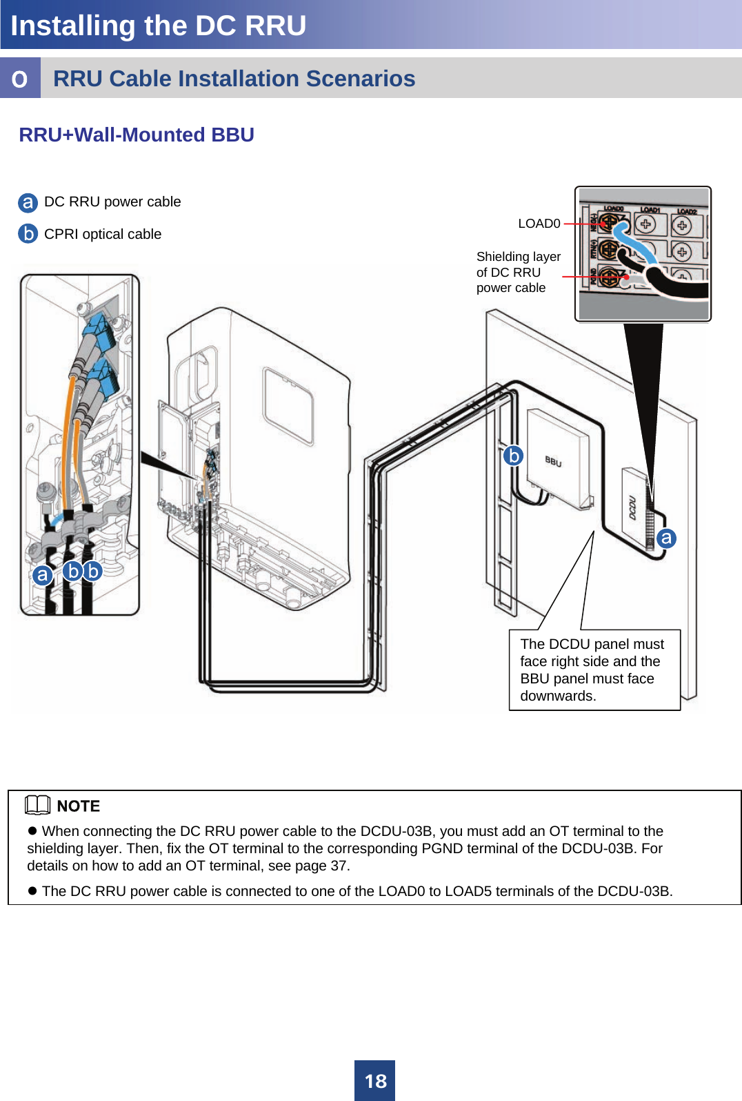
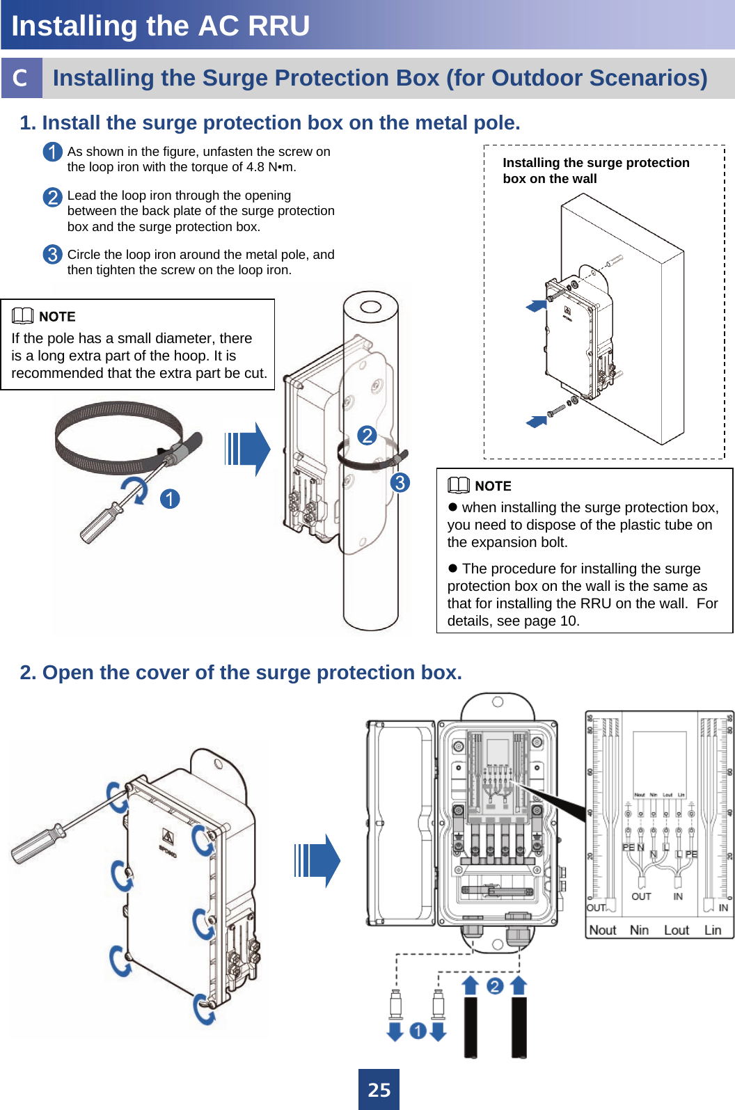
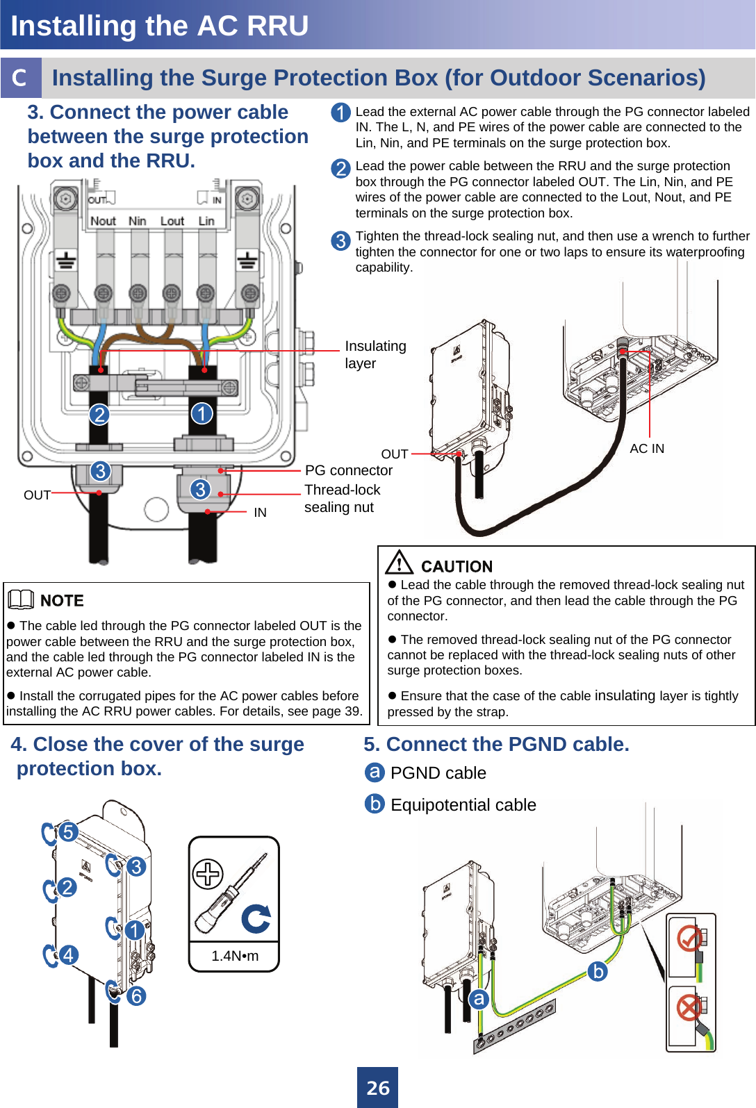
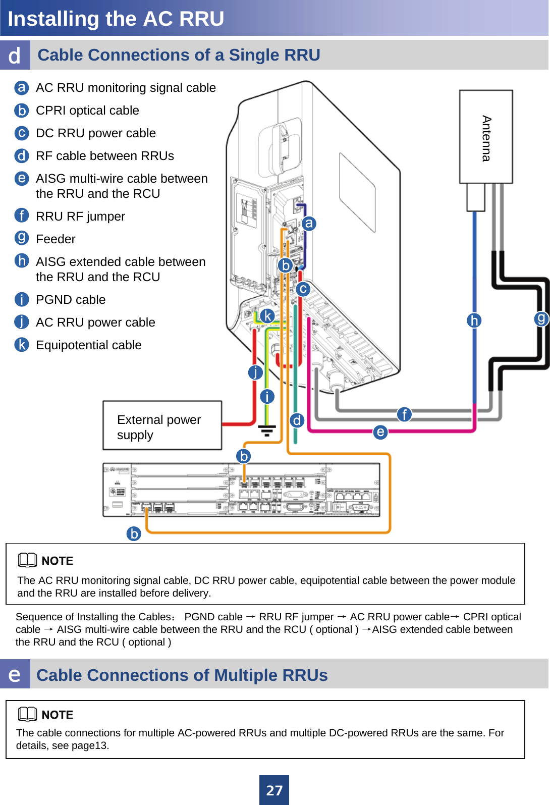
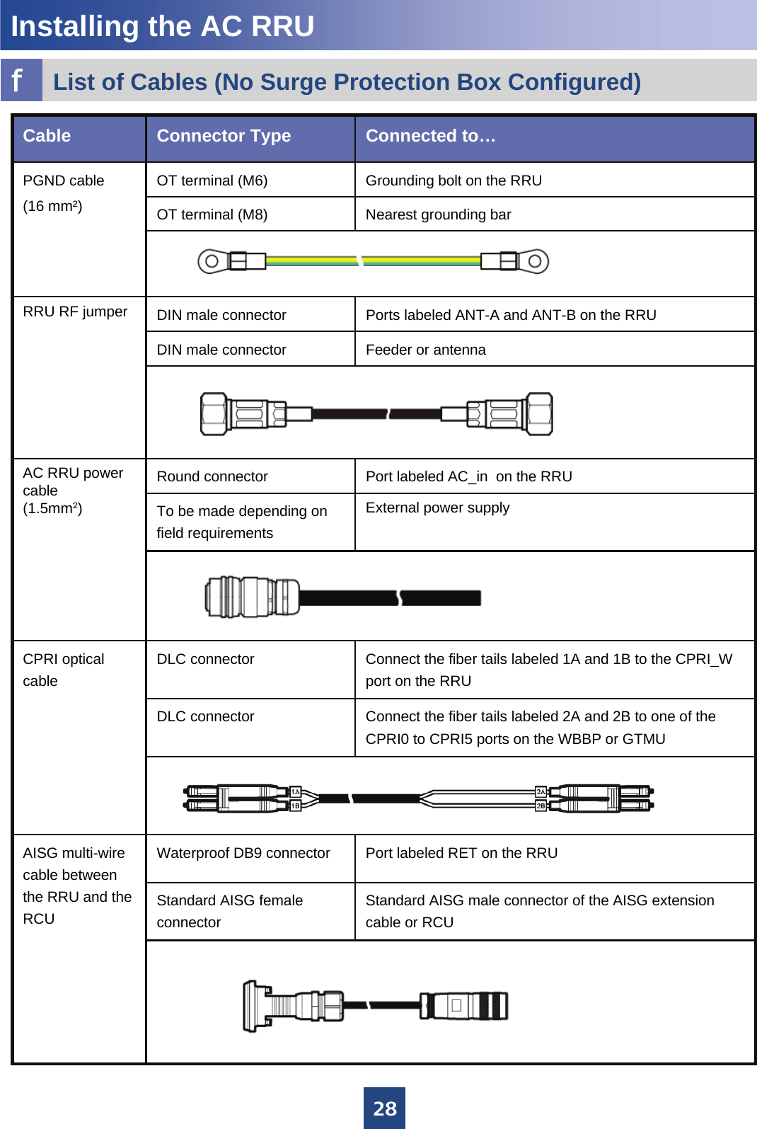
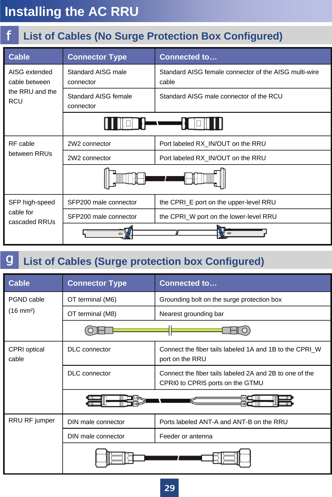
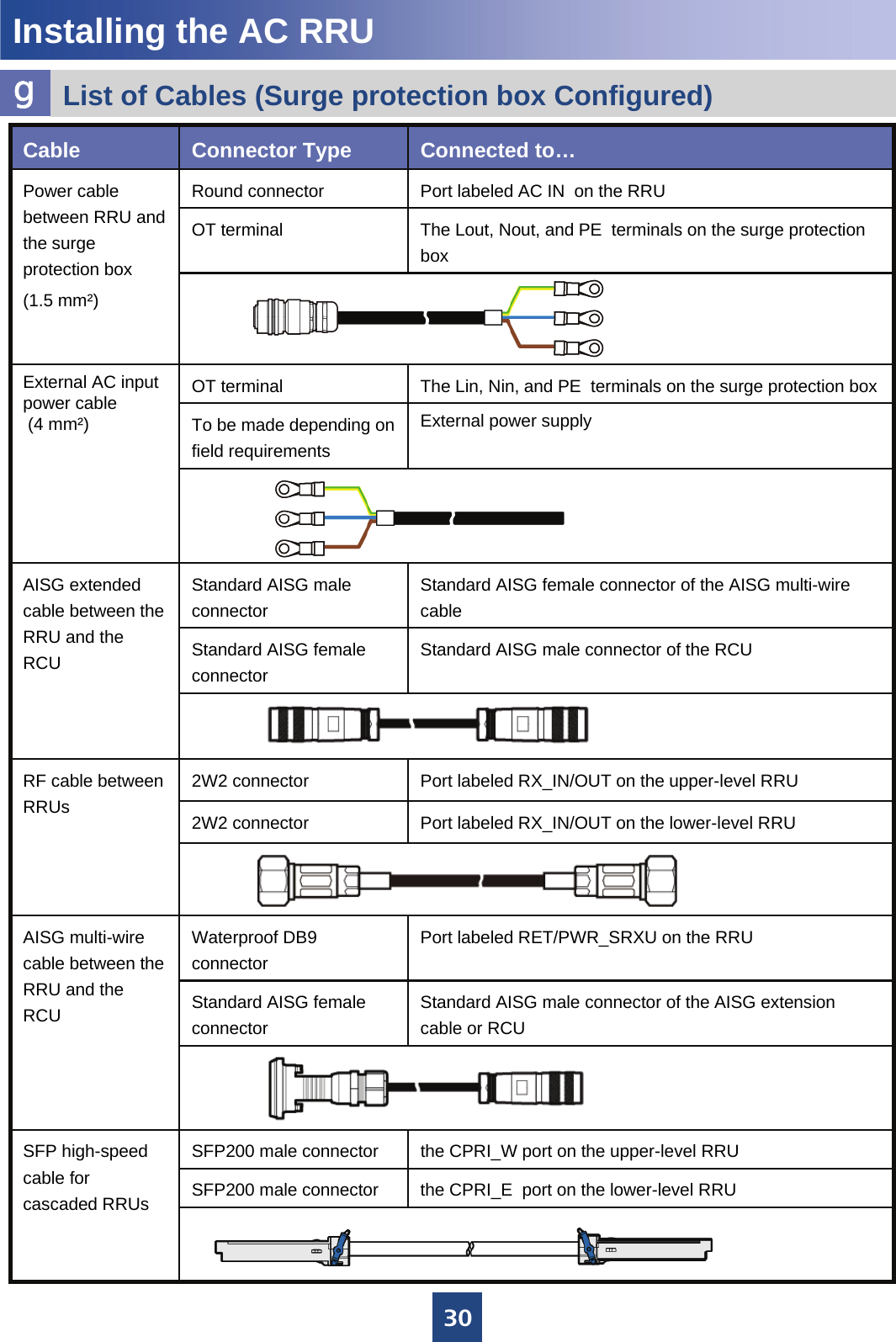
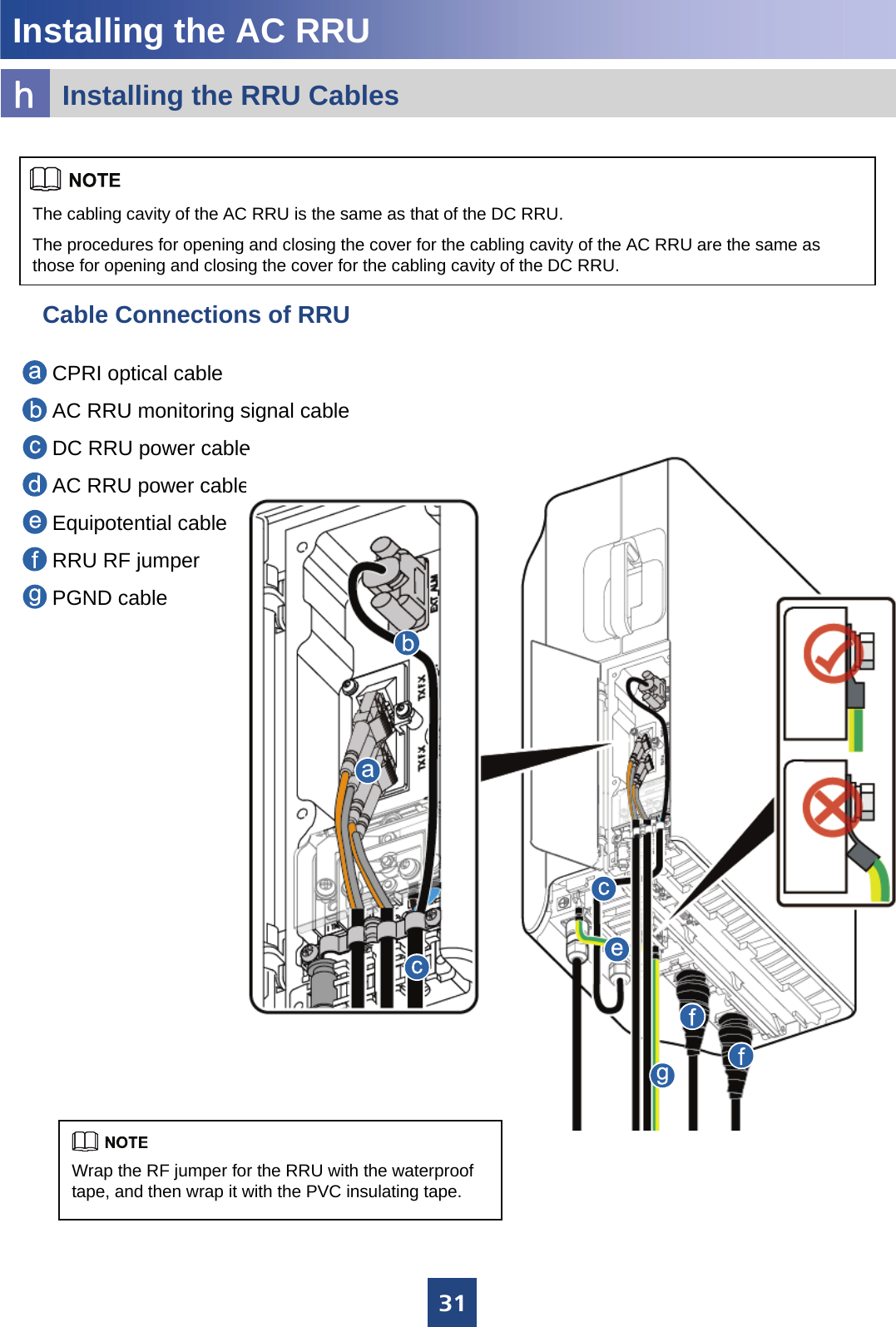
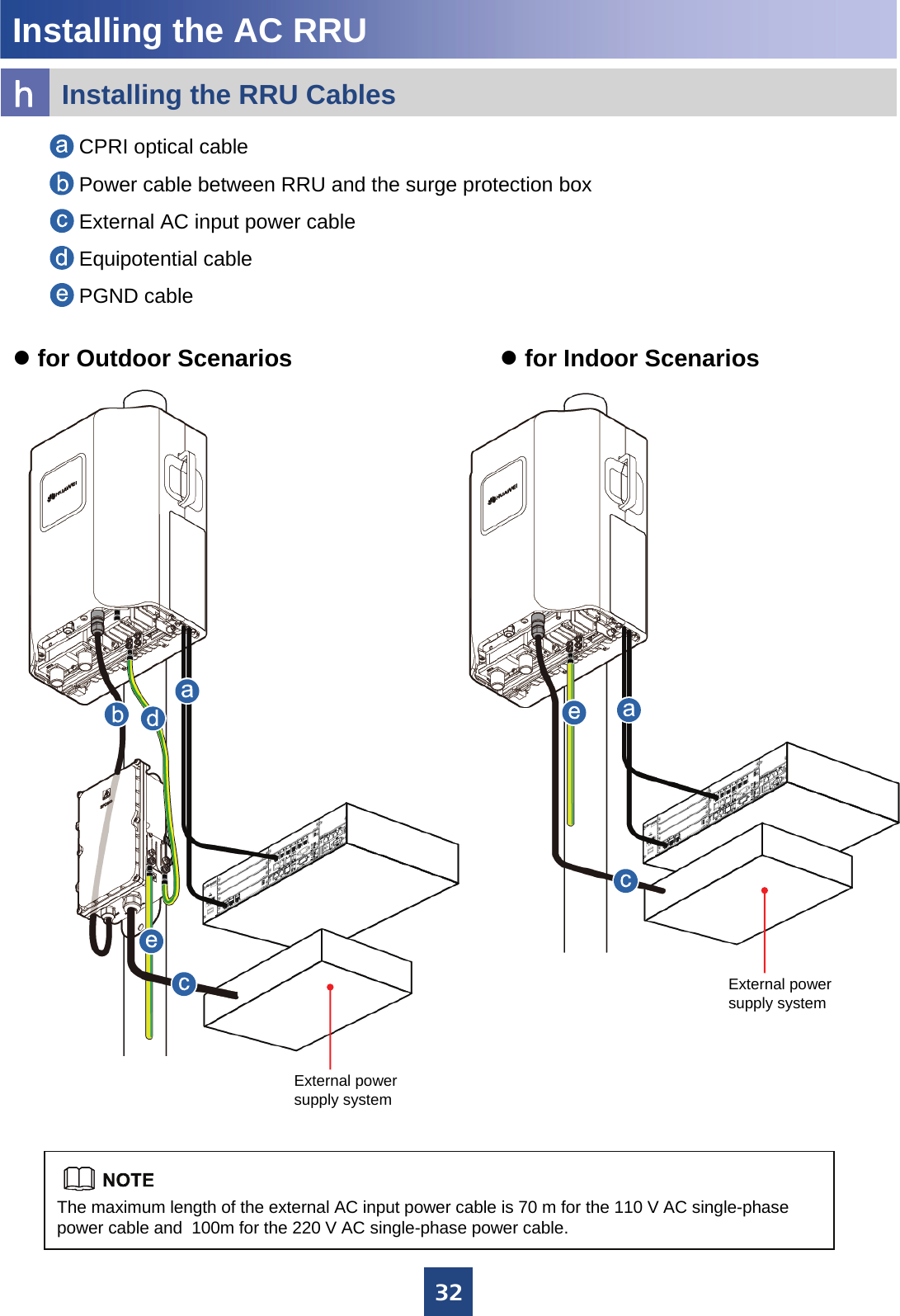
Installation Guide

HUAWEI TECHNOLOGIES Co., Ltd.RRU3908 V1   V100R003Installation GuideIssue: 02Date: 2010-07-20
1ContentsCopyright © Huawei Technologies Co., Ltd. 2010. All rights reserved.1. Installation Tools …………………………………………………………………………………………….2. Installing the DC RRU ………………………………………………………………………………………Installation Modes ……………………………………………………………………………………. Space Requirements …………………………………………………………………….. …………Installation Procedure ………………………………………………………………………………….Preparing for the installation ………………………………………………………………………….Installing the RRU on a Metal Pole ………………………………………………………………….Installing the RRU on a U-Steel …………………………………………………………………….Installing the RRU on an Angle Steel ………………………………………………………………Installing the RRU on a Wall …………………………………………………………………………Cable Connections of a Single RRU ………………………………………………………………Cable Connections of Multiple RRUs ………………………………………………………………Cable List ……………………………………………………………………………………………...Installing the RRU Cables ……………………………………………………………………………RRU Cable Installation Scenarios …………………………………………………………………3. Installing the AC RRU ………………………………………………………………………………... ……Space Requirements ………………………………………………………………….. ……………Installation Modes ……………………………………………………………………………………Installing the Surge Protection Box (for Outdoor Scenarios) ……………………………………Cable Connections of a Single RRU ……………………………………………………………….Cable Connections of Multiple RRUs ………………………………………………………………List of Cables (No Surge Protection Box Configured) ……………………………………………List of Cables (Surge protection box Configured) ………………………………………………...Installing the RRU Cables ……………………………………………………………………………Installation Checklist ………………………………………………………………………………….4. Powering On the RRU ………………………………………………………………………………………5. Appendix  ……………………………………………………………………………………………………Binding the RRU and Installation Components …………………………………………………..Making OT Terminals by Using a Cable Peeler (Recommended) ……………………………...Making OT Terminals at the Input End of the Power Cable by Using a Knife …………………Waterproofing Outdoor Cables ……………………………... ………………………………………Installing the Optical Module …………………………………………………………………………Installing the Corrugated Pipes of AC Power Cable ……………………………………………..Pin Assignment for the Wires of the RRU Alarm Cable (DC) ……………………………………6. Changes History ……………………………………………………………..………..…………..……….2334667991013131416182323232427272829313334343436373838393940
2Installation Tools5mmM3~M6MultimeterGuarded blade utility knife Hammer drill (with bit 14) Vacuum cleanerRubber hammerESD glovesHeat gunFlat-head screwdriver(M3~M6)Wire stripperWire cutterAdjustable wrench(with the diameter of at least 32 mm)Measuring tapeLevelMarking pen(with the diameter of no more than 10 mm)Combination wrench(21mm~21mm) for pole installation(17mm~17mm) for wall installationPhillips screwdriver(M3~M6)Torque wrenchCrimping pliersTorque screwdriver
3On a metal pole On a wallOn an angle steelOn a U-steelaInstallation ModesInstalling the DC RRU 63mm~80mm63 mm to 80 mm63 mm to 80 mm50 mm to 100 mm30 mm to 50 mm≤10°RRUAngle steel or U-steelThe following figure describes the specifications for the metal pole, angle steel, and U-steel where the RRU is installed.Angle steel U-steelThe brackets cannot be combined when the RRUsare installed on the wall.zA maximum of two RRUs can be installed on a metal pole with the diameter of 60 mm to 76 mm, and the RRUs must be installed on the back.zOnly one RRU can be installed on a U-steel or an angle steel at the back. zWhen installed on a tower, only one RRU can be installed in standard mode or reverse mode, and two RRUs cannot be installed in back-to-back mode, or the brackets cannot be combined when the RRUs are installed on the tower.zA single DC RRU can be bound and lifted to a tower. For details, see page 34 "Binding the RRU and Installation Components." WARNINGThe angle between the vertical and the angle steel or U-steel or angle steel where the RRU is installed must be less than or equal to 10 degree.60 mm to 114 mm(The recommended value is 80 mm.)Metal pole
4Installing the DC RRUbDimensions and Installation ClearanceMinimum Clearance for a Single RRURRU Dimensions≥300 mm≥500 mm≥800 mm≥600 mm≥300 mm380 mm 170 mm485 mmThe minimum installation clearance meets the requirements of the equipment for normal running and heat dissipation, but does not meet the requirements for Operation and Maintenance (OM) such as checking the status of the LEDs and opening the maintenance cavity. When the installation space is restricted, the minimum installation clearance can be adopted.The recommended installation clearance meets the requirements of the equipment for normal running and OM. When the installation space is sufficient, the recommended installation clearance can be adopted.Minimum clearance for the RRU installed on a tower200 mm300 mm400 mm100 mm600 mm400 mm100 mm600 mmTop view200 mm300 mm280 mm400 mm400 mm 280 mmAuxiliary metal poleMain metal poleSide viewTop viewMain metal poleAuxiliary metal poleRecommended Clearance for a Single RRU280 mm
5≥300 mm ≥600 mm ≥600 mm 100 mm 400 mm 400 mm≥500 mm≥500 mm≥300 mmRecommended Horizontal Spacing for Two RRUs Installed in Parallel Minimum Horizontal Spacing for Two  RRUs Installed in ParallelRecommended Vertical Spacing for Two RRUs Installed in Parallel Minimum Vertical Spacing for Two RRUs Installed in ParallelInstalling the DC RRU 300 mm300 mm200 mmbDimensions and Installation Clearance
6cInstallation ProceduredPreparing for the InstallationInstalling the DC RRU Dual-nut boltMain bracketAuxiliary bracketCover plate Attachment plateMain and auxiliary brackets for the RRU Front Back
71200 mm~1600 mm40N•mWhen installing the main bracket, ensure that the contact piece on the bracket is fixed.You may fit one end of the auxiliary bracket on one dual-nut bolt assembly and then the other end on the other dual-nut bolt assembly during the installation.Fasten the two dual-nut bolt assemblies alternatively. After the brackets are secure, use a tape to measure the spacing between the main bracket and the auxiliary bracket at the two sides and ensure that the spacing is the same.zThe weight-bearing capacity of the RF ports at the bottom of the RRU is low. Do not place the RRU at its bottom.zDuring the operation, place the foam pad or cardboard under the RRU to prevent any damage to the housing of the RRU. 2. Use an adjustable wrench to tighten the nut until the fastening torque is 40 N·m. In this way, the main and auxiliary brackets are secured on the pole.1. Install the main bracket.eInstalling a Single RRU on a Metal Pole3. Install the RRU on the main bracket. When you hear click sound, you can infer that the RRU is in position.Installing the DC RRU
15Installing the DC RRU lCable ListExternal alarm devicesEight cord end terminalsPort labeled EXT_ALM in the RRU cabling cavityDB15 male connectorDC RRU alarm cablePort labeled RX_IN/OUT on the  lower-level RRU2W2 connectorPort labeled RX_IN/OUT on the upper-level RRU2W2 connectorRF cable between RRUsthe CPRI_W  port on the lower-level RRUSFP200 male connectorthe CPRI_E port on the upper-level RRUSFP200 male connectorSFP high-speed cable for cascadingStandard AISG male connector of the RCUStandard AISG female connectorStandard AISG female connector of the AISG multi-wire cableStandard AISG male connectorAISG extended cable between the RRU and the RCUStandard AISG male connector of the AISG extension cable or RCUStandard AISG female connectorPort labeled RET on the RRUWaterproof DB9 connectorAISG multi-wire cable between the RRU and the RCUConnected to…Connector TypeCable
16Installing the DC RRUmInstalling the RRU Cables1. Opening the Cover Plate of the RRU Cabling Cavity2. The Cabling Cavity of  the RRUCover plate of the cabling cavityCabling cavityReference for makingthe power cableM4Waterproofing fillerCable trough for the power cableCable trough for the optical cableCable trough for the power cable
171.4N•mM4nInstalling the RRU CablesInstalling the DC RRU 3. Cable Connections of RRU4. Closing the Cover Plate of the RRU Cabling Cavity.zThe screw on the cover plate is tightened until the fastening torque is 14 kgf•cm.zThe screws on the cover plate are tightened in the order shown in the preceding figure.zThe tape is wrapped spirally upwards, downwards, and then upwards again in three layers. For every two adjacent tape layers, the tape on the upper layer overlaps about half the width of the tape on the lower layer.zFor details on how to add the OT terminals to the DC RRU power cable, see page 36.zPress the strap on the exposed shielding layer of the power cable tightly. Ensure that the lower edge of the exposed shield layer does not exceed the position shown in the figure.zThe alarm cable is preferably led out of the RRU from the narrower cable trough in the middle of the cabling cavity. If the cable trough is used by the CPRI optical cable, the alarm cable is led from the wider cable trough near the middle one. In this case, the alarm cable must be wrapped with 10 to 17 layers of waterproof tape so that the diameter of the cable reaches 10 mm to 12 mm.zTo avoid sharp bending, the optical cable must be pressed by thestrap next to the power cable during the optical cable installation.zWaterproof fillers should be installed in the unused cable trough. Waterproofed alarm cableShielding layer of the power cableDC RRU alarm cableCPRI optical cableDC RRU power cablePGND cableRRU RF jumperCase 2 Case 1Do not remove the dustproof cap from the feeder connectors that are not in use. In addition, protection measures against damp, dust, and salt mist must be taken. If the RRU is installed outdoors, you also need to wrap the joint with waterproof tape, as shown in the following figures.Waterproof tapeDustproof capInsulating tapeInsulating tape
18RRU+Wall-Mounted BBUoRRU Cable Installation ScenariosInstalling the DC RRU DC RRU power cableCPRI optical cableThe DCDU panel must face right side and the BBU panel must face downwards. LOAD0Shielding layer of DC RRU power cablezWhen connecting the DC RRU power cable to the DCDU-03B, you must add an OT terminal to the shielding layer. Then, fix the OT terminal to the corresponding PGND terminal of the DCDU-03B. For details on how to add an OT terminal, see page 37.zThe DC RRU power cable is connected to one of the LOAD0 to LOAD5 terminals of the DCDU-03B.
19LOAD0RRU+PS4890Installing the DC RRU Shielding layer of DC RRU power cableDC RRU power cableCPRI optical cableoRRU Cable Installation ScenarioszWhen connecting the DC RRU power cable to the DCDU-03B, you must add an OT terminal to the shielding layer. Then, fix the OT terminal to the corresponding PGND terminal of the DCDU-03B. For details on how to add an OT terminal, see page 37.zThe DC RRU power cable is connected to one of the LOAD0 to LOAD5 terminals of the DCDU-03B.
20The DC RRU power cable is connected to terminals of the 4815 power system for RRU.Installing the DC RRU oRRU Cable Installation Scenarios220 V AC input (4815 installed in the OMB cabinet).–48 V DC input (DCDU-03C installed in the OMB cabinet).The DC RRU power cable is connected to one of the LOAD0 to LOAD5 terminals of the DCDU-03B.Metal Shielding layer (25 mm) PGND cableGrounding the shielding layer of the power cable:Metal Shielding layer (25 mm) PGND cableGrounding the shielding layer of the power cable:DC RRU power cableCPRI optical cableDC RRU power cableCPRI optical cable
8Cabling cavityIn standard mode In reverse modeInstalling Two RRUs Back-To-Back on a Metal Polef4. Install the second RRU on the main bracket.3. Reinstall the attachment plate and cover plate on the second RRU by interchanging their positions.1. Install an RRU. For details, see page 6 Installing a Single RRU on a Metal Pole.2. Install the main fixture for another RRU.Ensure that the cabling cavities of the two RRUs face the same direction when installing the RRUs.5N•mM6X16Installing the DC RRU
9gInstalling the RRU on a U-SteelhInstalling the RRU on an Angle SteelInstalling the DC RRU zThe procedure for installing the RRU on a U-steel is the same as that on a metal pole.zOnly one RRU can be installed on a U-steel. zThe procedure for installing the RRU on an angle steel is the same as that on a metal pole.zOnly one RRU can be installed on an  angle steel. U-steelPlan viewPlan viewAngle steel
10Ø14After the expansion bolt is removed, dispose of the plastic tube.90°55 mm to 60 mm20 mm to 30 mmM10x65 boltSpring washer 10Plastic tubeFlat washer 10Expansion tubeDo not hammer the bolt entirely into the wall. Instead, leave 20 mm to 30 mm of the bolt outside the wall.iInstalling the RRU on a WallInstalling the DC RRU 2. Drill holes at the anchor points and then install the expansion bolt assemblies.When the RRU is installed on a wall, the requirements are as follows:zFor one RRU, the wall has a weight-bearing capacity of 92 kg.zThe fastening torque of the expansion bolt reaches 30 N·m, the expansion bolt works properly, and no damages such as cracks are on the wall. 1. Place the auxiliary fixture on the wall at the installation position and then mark the anchor points by using a marking pen.zIt is recommended that the auxiliary bracket be 1,200 mm to 1,600 mm above the ground.zThe RRUs cannot installed on a wall in centralized mode. Therefore, expansion bolt assemblies should be prepared for each RRU. 1200 mm~1600 mm128 mm126 mmAuxiliary bracket126 mmRRU
11iInstalling the RRU on a WallInstalling the DC RRU Arrows are upwards30N•mM103. Fit the auxiliary bracket on the expansion bolts downward, and then tighten the bolts by using a combination wrench 17 mm.4. Install the main bracket.5. Install the RRU.
126. Install multiple RRUs.≥70 mm ≥70 mm650 mmMinimum Clearance:Recommended Clearance :≥760 mm ≥760 mmiInstalling the RRU on a WallInstalling the DC RRU ≥730 mm≥430 mm650 mm 530 mm230 mm≥535 mm ≥535 mm
13When a dual-polarized antenna is shared by two RRUs in the same sector, the two RRUs are connected through an RF cable between RFUs. The connections of three RRUs in the same sector are not supported.jCable Connections of a Single RRUkCable Connections of Multiple RRUsInstalling the DC RRU This figure shows only the CPRI optical cable connections. For details on the connections of  other cables, see the cable connections for a single RRU.External alarm deviceExternal power supplyRCUDC RRU alarm cableCPRI optical cableDC RRU power cableRF cable between RFUsAISG multi-wire cable between the RRU and the RCURRU RF jumperFeederAISG extended cable between the RRU and the RCUPGND cableAntennaInstall the PGND cableInstall the RF jumper(RF cable between RFUs is optional)Install the DC RRU power cable Install the CPRI optical cableInstall the DC RRU alarm cable(optional)Install the AISG multi-wire cable between the RRU and the RCU(optional)Install the AISG multi-wire cable between the RRU and the RCU(optional)
14lCable ListInstalling the DC RRU Connect the fiber tails labeled 1A and 1B to the CPRI_W port on the RRUDLC connectorCPRI optical cableConnect the fiber tails labeled 2A and 2B to one of the CPRI0 to CPRI5 ports on the WBBP or GTMUDLC connectorzNorth American standard: The OT terminal on the blue wire is connected to the NEG(-) port on the cabling cavity of the RRU. The OT terminal on the black wire is connected to the RTN(+) port on the cabling cavity of the RRUzEuropean standard: The OT terminal on the blue wire is connected to the NEG(-) port on the cabling cavity of the RRU. The OT terminal on the brown wire is connected to the RTN(+) port on the cabling cavity of the RRUTwo OT terminals ( M4 )DC RRU power cable( North American standard: 2AWGEuropean standard: 4 mm² )External power supplyBare wireFeeder or antennaDIN male connectorPorts labeled ANT-A and ANT-B on the RRUDIN male connectorRRU RF jumperNearest grounding barOT terminal ( M8 )Grounding bolt on the RRUOT terminal ( M6 )PGND cable(16 mm²)Connected to…Connector TypeCableNorth American standard: European standard: North American standard: European standard:
22RRU+TMCInstalling the DC RRU DC RRU power cableCPRI optical cableoRRU Cable Installation ScenariosMetal Shielding layer (25 mm) PGND cableGrounding the shielding layer of the power cable:zWhen connecting the DC RRU power cable to the DCDU-03B, you must add an OT terminal to the shielding layer. Then, fix the OT terminal to the corresponding PGND terminal of the DCDU-03B. For details on how to add an OT terminal, see page 37.zThe DC RRU power cable is connected to one of the LOAD0 to LOAD5 terminals of the DCDU-03B.zThree power cables can be led through each ground clip.
23Space RequirementsabInstallation ModesbInstalling the AC RRUThe AC RRU cannot be installed at the side. When it is installed in other modes, the procedure is the same as that of the DC RRU. For details, see page 6. 380 mm 250 mm485 mmOn a metal pole On a wallOn an angle steelOn a U-steelThe recommended/minimal clearance for the AC RRU/clearance for Two Combined RRUs is the same as that for the DC RRU. For details, see page 4 and page 5.
24Installing the Surge Protection Box (for Outdoor Scenarios)cDimensions of the surge protection box.Recommended clearance for the surge protection box.Installation of the surge protection box.Installing the AC RRUHoop iron 140 mm240 mm305 mm75 mm≥100 mm≥500 mm≥500 mm≥500 mm≥100 mm50 mm300 mm300 mm300 mm50 mmMinimal clearance for the surge protection box.
252. Open the cover of the surge protection box. 1. Install the surge protection box on the metal pole. As shown in the figure, unfasten the screw on the loop iron with the torque of 4.8 N•m.Lead the loop iron through the opening between the back plate of the surge protection box and the surge protection box.Circle the loop iron around the metal pole, and then tighten the screw on the loop iron. Installing the surge protectionbox on the wallInstalling the AC RRUInstalling the Surge Protection Box (for Outdoor Scenarios)cIf the pole has a small diameter, there is a long extra part of the hoop. It is recommended that the extra part be cut. zwhen installing the surge protection box, you need to dispose of the plastic tube on the expansion bolt.zThe procedure for installing the surge protection box on the wall is the same as that for installing the RRU on the wall.  For details, see page 10.
26Installing the AC RRUInstalling the Surge Protection Box (for Outdoor Scenarios)cOUT AC ININOUT1.4N•mPG connectorThread-locksealing nutLead the external AC power cable through the PG connector labeled IN. The L, N, and PE wires of the power cable are connected to the Lin, Nin, and PE terminals on the surge protection box.Lead the power cable between the RRU and the surge protection box through the PG connector labeled OUT. The Lin, Nin, and PE wires of the power cable are connected to the Lout, Nout, and PEterminals on the surge protection box.Tighten the thread-lock sealing nut, and then use a wrench to further tighten the connector for one or two laps to ensure its waterproofing capability. 3. Connect the power cable between the surge protection box and the RRU. 5. Connect the PGND cable. zThe cable led through the PG connector labeled OUT is the power cable between the RRU and the surge protection box, and the cable led through the PG connector labeled IN is the external AC power cable.zInstall the corrugated pipes for the AC power cables before installing the AC RRU power cables. For details, see page 39.zLead the cable through the removed thread-lock sealing nut of the PG connector, and then lead the cable through the PG connector.zThe removed thread-lock sealing nut of the PG connector cannot be replaced with the thread-lock sealing nuts of other surge protection boxes.zEnsure that the case of the cable insulating layer is tightly pressed by the strap.4. Close the cover of the surgeprotection box.  PGND cableEquipotential cableInsulating layer
27Cable Connections of a Single RRUdInstalling the AC RRUCable Connections of Multiple RRUseThe cable connections for multiple AC-powered RRUs and multiple DC-powered RRUs are the same. For details, see page13.The AC RRU monitoring signal cable, DC RRU power cable, equipotential cable between the power module and the RRU are installed before delivery. Sequence of Installing the Cables:PGND cable →RRU RF jumper →AC RRU power cable→CPRI optical cable →AISG multi-wire cable between the RRU and the RCU ( optional ) →AISG extended cable between the RRU and the RCU ( optional ) AntennaAC RRU monitoring signal cableCPRI optical cableDC RRU power cableRF cable between RRUsAISG multi-wire cable between the RRU and the RCURRU RF jumperFeederAISG extended cable between the RRU and the RCUPGND cableAC RRU power cableEquipotential cable External power supply
28List of Cables (No Surge Protection Box Configured)fInstalling the AC RRUPorts labeled ANT-A and ANT-B on the RRUDIN male connectorRRU RF jumperFeeder or antennaDIN male connectorPort labeled AC_in on the RRURound connectorAC RRU power cable(1.5mm²)External power supplyTo be made depending on field requirementsConnect the fiber tails labeled 1A and 1B to the CPRI_W port on the RRUDLC connectorCPRI optical cableConnect the fiber tails labeled 2A and 2B to one of the CPRI0 to CPRI5 ports on the WBBP or GTMUDLC connectorPort labeled RET on the RRUWaterproof DB9 connectorAISG multi-wire cable between the RRU and the RCUStandard AISG male connector of the AISG extension cable or RCUStandard AISG female connectorNearest grounding barOT terminal (M8)Grounding bolt on the RRUOT terminal (M6)PGND cable(16 mm²)Connected to…Connector TypeCable
29List of Cables (No Surge Protection Box Configured)fInstalling the AC RRUthe CPRI_E port on the upper-level RRUSFP200 male connectorSFP high-speed cable for cascaded RRUs the CPRI_W port on the lower-level RRUSFP200 male connectorStandard AISG female connector of the AISG multi-wire cableStandard AISG male connectorAISG extended cable between the RRU and the RCU Standard AISG male connector of the RCUStandard AISG female connectorPort labeled RX_IN/OUT on the RRU2W2 connectorRF cable between RRUs Port labeled RX_IN/OUT on the RRU2W2 connectorConnected to…Connector TypeCableList of Cables (Surge protection box Configured)gConnect the fiber tails labeled 2A and 2B to one of the CPRI0 to CPRI5 ports on the GTMUDLC connectorConnect the fiber tails labeled 1A and 1B to the CPRI_W port on the RRUDLC connectorCPRI optical cableConnected to…Connector TypeCableFeeder or antennaDIN male connectorPorts labeled ANT-A and ANT-B on the RRUDIN male connectorRRU RF jumperNearest grounding barOT terminal (M8)Grounding bolt on the surge protection boxOT terminal (M6)PGND cable(16 mm²)
30List of Cables (Surge protection box Configured)gInstalling the AC RRUthe CPRI_W port on the upper-level RRUSFP200 male connectorSFP high-speed cable for cascaded RRUs the CPRI_E  port on the lower-level RRUSFP200 male connectorPort labeled RET/PWR_SRXU on the RRUWaterproof DB9 connectorAISG multi-wire cable between the RRU and the RCU Standard AISG male connector of the AISG extension cable or RCUStandard AISG female connectorStandard AISG female connector of the AISG multi-wire cableStandard AISG male connectorAISG extended cable between the RRU and the RCU Standard AISG male connector of the RCUStandard AISG female connectorThe Lin, Nin, and PE  terminals on the surge protection box OT terminalExternal AC input power cable(4 mm²) External power supplyTo be made depending on field requirementsPort labeled RX_IN/OUT on the lower-level RRU2W2 connectorPort labeled RX_IN/OUT on the upper-level RRU2W2 connectorRF cable between RRUsPort labeled AC IN  on the RRURound connectorPower cable between RRU and the surge protection box(1.5 mm²)The Lout, Nout, and PE  terminals on the surge protection box OT terminalConnected to…Connector TypeCable
31hInstalling the RRU CablesThe cabling cavity of the AC RRU is the same as that of the DC RRU.The procedures for opening and closing the cover for the cabling cavity of the AC RRU are the same as those for opening and closing the cover for the cabling cavity of the DC RRU.Installing the AC RRUCable Connections of RRUCPRI optical cableAC RRU monitoring signal cableDC RRU power cable AC RRU power cable Equipotential cableRRU RF jumperPGND cableWrap the RF jumper for the RRU with the waterproof tape, and then wrap it with the PVC insulating tape.
32Installing the AC RRUThe maximum length of the external AC input power cable is 70 m for the 110 V AC single-phase power cable and  100m for the 220 V AC single-phase power cable.zfor Outdoor Scenarios  zfor Indoor Scenarios External power supply systemExternal power supply systemhInstalling the RRU CablesCPRI optical cablePower cable between RRU and the surge protection boxExternal AC input power cableEquipotential cablePGND cable
33Installing the AC RRUInstallation Checklisti3. The OT terminals of the cables connected to the surge protection box are securely linked. The jackets of the cables are not damaged, and there are no uneven edges on the cables.2. The waterproof gaskets on the door of the cabling cavity of the surge protection box are not stripped or broken.1. The PG connectors labeled IN and OUT on the surge protection box are securely installed and cannot be rotated with the cables. 5. The six screws on the cabling cavity of the surge protection are tightened according to the required fastening torque.4. The PG connectors are tightened, and the waterproof rings are secure. 9. The installation and maintenance of the surge protection box is not performed in rainy or damp weather.8. The power supply to the surge protection box is cut off before installation and maintenance.7. The cables in the surge protection box are correctly connected by referring to the operation guide. The OT terminals are tight linked before the door of the cabling cavity is closed.6. The axis for the door of the cabling cavity of the surge protection box is not broken, and the surface of the protection box is not scratched.
34StartEndPower on the RRUCheck whether the status of the RUN LED is 1s ON, 1s OFF and that of ALM LED is OFF.Rectify the faultYesNoPowering On the RRUAppendixaBinding the RRU and Installation Components1. Bind the RRU by leading the lifting rope along the lower part of the adapting piece and through the handle, bind the main and auxiliary brackets with the lifting rope, and then bind the steering rope with the handle of the RRU, as shown in the following figures.Lifting ropeLower part of the adapting pieceSteering ropeDo not bind the lifting rope only on the handle when lifting the RRU.zWhen lifting the RRU and installation components to the tower, prevent the RRU from colliding with the tower.zThe cross-sectional area of the lifting rope and steering rope is around 20 mm, not more than 25 mm. In addition, the ropes can bear the weight four times more than that of the RRU.When the RRU is unpacked, it must be powered on within 24 hours.
35zInstaller A climbs onto the tower. Then, installer A fixes the pulley to the support of the tower platform and leads the lifting rope through the pulley. zInstaller C uses a lifting rope to bind the RRU and installation components as shown in the preceding figure and then ties a knot in the steering rope at the handle of the RRU.zInstaller B pulls the lifting rope, and at the same time, installer C pulls the steering rope away from the tower to prevent the RRU and installation components from colliding with the tower.zInstaller A holds the RRU and installation components and untie the ropes.Steering ropeLifting ropePulleyAppendixzCut off a 200 mm long corrugated pipe with the diameter of 25 mm.zLead the fiber tails labeled 1A and 1B of the optical cable into the corrugated pipe by 160 mm. zWrap up the corrugated pipe and optical cable with the color tape. zFor the tower made of steel pipes, tie the black jacket to the corrugated pipe at the position 150 mm away from the color tape, and then lift the optical cable up to the tower.zFor the tower made of angle steel girders, carry the optical cable onto the tower when climbing up to the tower.zAfter the optical cable is lifted up to the tower, remove the color tape and corrugated pipe before installing the optical cable.3. Lifting the CPRI Optical Cable up to the TowerBinding the RRU and Installation Componentsa2. Lifting the RRU and Installation Components to the TowerColor tapeCorrugated pipe
3615mm8mm14mm010203040AppendixMaking OT Terminals by Using a Cable Peeler (Recommended)bAdd two OT terminals to the end of the power cable connecting to the RRU.The assembling of OT terminals to the power cable must be complete before the RRU is installed on a metal pole.Determine lengths of power cables for different operations according to the scales on the inner side of the cover plate of the cabling cavity.Based on the determined length, remove the jacket and shielding layer off the power cable.Add an OT terminal to each wire.Strip a 15 mm jacket off the power cable to reveal the shielding layer of the power cableRemove the jacket from each wire.Label for preparing the power cable-48V DC power cableShielding layerOT terminalsNEG ( - )RTN ( + )
37AppendixcDo not damage the shielding layer of the power cable when cutting around the jacket.WARNINGLead the wires made of the shielding layers through heat-shrinkable tubes.Wrap the PVC insulating tape at the joint where the three wires meet. OT terminal on the shielding layerAdding OT Terminals to the Power Cable on the DCDU side
38Waterproofing Outdoor CablesdzThe waterproof tape should be wrapped for an extra length of 20 mm away from the connectors at both ends. zThe tapes should be wrapped around the connector from the lower part to the upper part. When wrapped for another layer, the tapes may not be cut.zWhen wrapping the waterproof tape, apply even force to extend the tape until the width of the tape is 1/2 of the original width. zWhen wrapping the waterproof tape, ensure that the upper layer of the tape covers at least 50% of the lower layer. zThe insulating tape should be wrapped for an extra length of 20mm away from the connectors at both ends.zThe last layer of the waterproof tape should be wrapped from the lower part to the upper part to prevent rainwater from infiltrating into the tape. Waterproof tape Insulating tapeInstalling the Optical ModuleeTightly pressing the tape1. Wrap three layers of waterproof tape.2. Wrap three layers of insulating tape.Tightly pressing the tapeBinding cable ties at both ends of the tapetietieAppendix
39AppendixX9X8X7X6X5X4X3X2Cord End TerminalGNDOrangeGNDX1.7SWITCH_INPUT1+Twisted pairWhite/orangeSWITCH_INPUT1+X1.6GNDBlueGNDX1.3SWITCH_INPUT0+Twisted pairWhite/blueSWITCH_INPUT0+X1.2APM TX+BrownRX485_RX+X1.14APM TX-Twisted pairWhite/ brownRX485_RX-X1.13APM RX+GreenRX485_TX+X1.11APM RX-Twisted pairWhite/ greenRX485_TX-X1.10LabelWire TypeWire ColorSignal name of DB15 connectorDB15 connectorWaterproof tapeszAfter the corrugated pipe is installed, wrap both ends of the power cable with waterproof tapes by referring to the following figure. zWrap the joint spirally upward, downward, and then upward again. That is, the joint is wrapped by three layers of the tape. Ensure that two adjacent layers overlap with each other about half the width of the tape.Power systemgPin Assignment for the Wires of the  RRU Alarm Cable ( DC )fInstalling the corrugated pipes of AC power cableCorrugated pipes Corrugated pipes Corrugated pipesConnector for corrugated pipesWaterproof tapes
40Changes HistoryThis page describes the changes in the RRU3908 V1 Installation Guide.z02 (2010-07-20)This is the first commercial release.Compared with (2010-05-04), the figure of the minimum clearance for RRU are optimized, and the minimum clearance for the RRU installed on a tower requirements is added.z01 (2010-05-04)This is the draft release.
HUAWEI TECHNOLOGIES CO., LTD.Huawei Industrial Base Bantian LonggangShenzhen 518129People’s Republic of Chinawww.huawei.com
21Installing the DC RRURRU+APM30/APM30HzThe DC RRU power cable is connected to one of the LOAD4 to LOAD9 terminals of the PDU.zStrip the jacket of the DC RRU power cable for a small part, press the exposed shielding layer on the strap, and then connect the PGND cable on the strap to the nearest grounding bolt on the side in the APM30/APM30H.zThree power cables can be led through each ground clip.DC RRU power cableCPRI optical cableoRRU Cable Installation ScenariosMetal Shielding layer (25 mm) PGND cableGrounding the shielding layer of the power cable:

Navigation menu