Huawei Technologies RRU3908-1900 Remote Radio Unit of Multi-Mode Distributed Base Station User Manual RRU3908 V1 Installation Guide
Huawei Technologies Co.,Ltd Remote Radio Unit of Multi-Mode Distributed Base Station RRU3908 V1 Installation Guide
Installation Guide

HUAWEI TECHNOLOGIES Co., Ltd.
RRU3908 V1
V100R003
Installation Guide
Issue: 02
Date: 2010-07-20

1
Contents
Copyright © Huawei Technologies Co., Ltd. 2010. All rights reserved.
1. Installation Tools …………………………………………………………………………………………….
2. Installing the DC RRU ………………………………………………………………………………………
Installation Modes …………………………………………………………………………………….
Space Requirements …………………………………………………………………….. …………
Installation Procedure ………………………………………………………………………………….
Preparing for the installation ………………………………………………………………………….
Installing the RRU on a Metal Pole ………………………………………………………………….
Installing the RRU on a U-Steel …………………………………………………………………….
Installing the RRU on an Angle Steel ………………………………………………………………
Installing the RRU on a Wall …………………………………………………………………………
Cable Connections of a Single RRU ………………………………………………………………
Cable Connections of Multiple RRUs ………………………………………………………………
Cable List ……………………………………………………………………………………………...
Installing the RRU Cables ……………………………………………………………………………
RRU Cable Installation Scenarios …………………………………………………………………
3. Installing the AC RRU ………………………………………………………………………………... ……
Space Requirements ………………………………………………………………….. ……………
Installation Modes ……………………………………………………………………………………
Installing the Surge Protection Box (for Outdoor Scenarios) ……………………………………
Cable Connections of a Single RRU ……………………………………………………………….
Cable Connections of Multiple RRUs ………………………………………………………………
List of Cables (No Surge Protection Box Configured) ……………………………………………
List of Cables (Surge protection box Configured) ………………………………………………...
Installing the RRU Cables ……………………………………………………………………………
Installation Checklist ………………………………………………………………………………….
4. Powering On the RRU ………………………………………………………………………………………
5. Appendix ……………………………………………………………………………………………………
Binding the RRU and Installation Components …………………………………………………..
Making OT Terminals by Using a Cable Peeler (Recommended) ……………………………...
Making OT Terminals at the Input End of the Power Cable by Using a Knife …………………
Waterproofing Outdoor Cables ……………………………... ………………………………………
Installing the Optical Module …………………………………………………………………………
Installing the Corrugated Pipes of AC Power Cable ……………………………………………..
Pin Assignment for the Wires of the RRU Alarm Cable (DC) ……………………………………
6. Changes History ……………………………………………………………..………..…………..……….
2
3
3
4
6
6
7
9
9
10
13
13
14
16
18
23
23
23
24
27
27
28
29
31
33
34
34
34
36
37
38
38
39
39
40
2
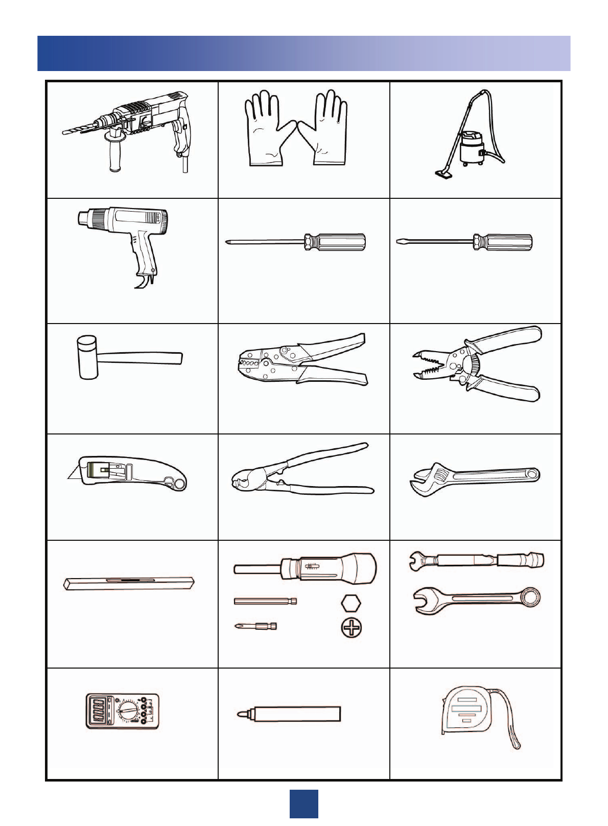
Installation Tools
5mm
M3~M6
Multimeter
Guarded blade utility knife
Hammer drill (with bit 14) Vacuum cleaner
Rubber hammer
ESD gloves
Heat gun
Flat-head screwdriver
(M3~M6)
Wire stripper
Wire cutter
Adjustable wrench
(with the diameter of at least 32 mm)
Measuring tape
Level
Marking pen
(with the diameter of no more
than 10 mm)
Combination wrench
(21mm~21mm) for pole installation
(17mm~17mm) for wall installation
Phillips screwdriver
(M3~M6)
Torque wrench
Crimping pliers
Torque screwdriver
3
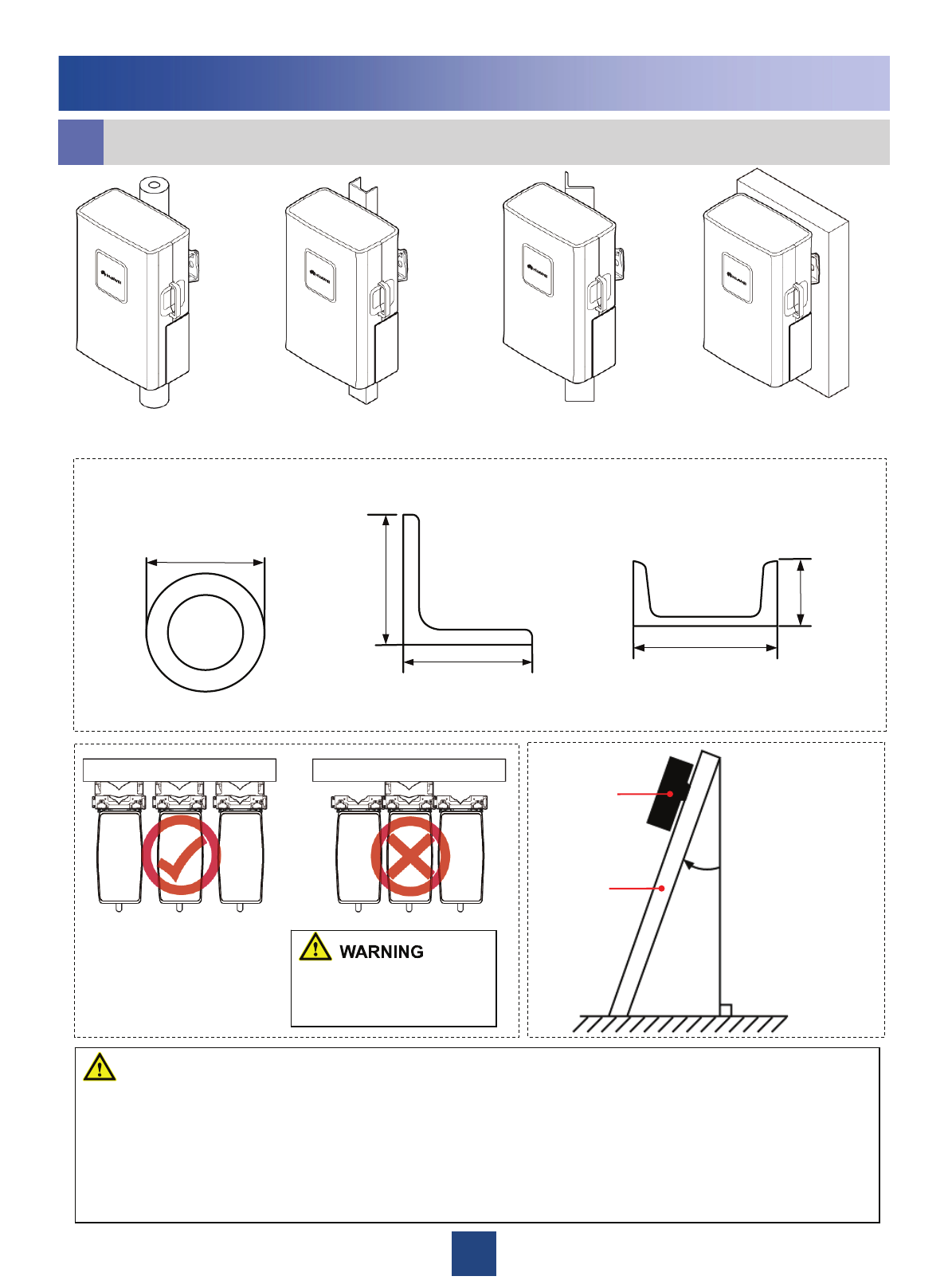
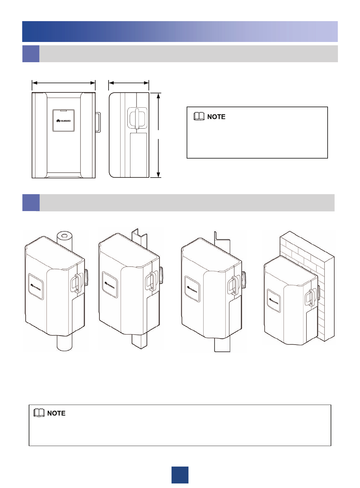
On a metal pole On a wall
On an angle steelOn a U-steel
aInstallation Modes
Installing the DC RRU
63mm
~
80mm
63 mm to 80 mm
63 mm to 80 mm
50 mm to 100 mm
30 mm to 50 mm
≤10°
RRU
Angle steel
or U-steel
The following figure describes the specifications for the metal pole, angle steel, and U-steel where the RRU is
installed.
Angle steel U-steel
The brackets cannot be
combined when the RRUs
are installed on the wall.
zA maximum of two RRUs can be installed on a metal pole with the diameter of 60 mm to 76 mm, and the
RRUs must be installed on the back.
zOnly one RRU can be installed on a U-steel or an angle steel at the back.
zWhen installed on a tower, only one RRU can be installed in standard mode or reverse mode, and two RRUs
cannot be installed in back-to-back mode, or the brackets cannot be combined when the RRUs are installed on
the tower.
zA single DC RRU can be bound and lifted to a tower. For details, see page 34 "Binding the RRU and
Installation Components."
WARNING
The angle between
the vertical and the
angle steel or U-
steel or angle steel
where the RRU is
installed must be
less than or equal
to 10 degree.
60 mm to 114 mm
(The recommended value is 80 mm.)
Metal pole
4
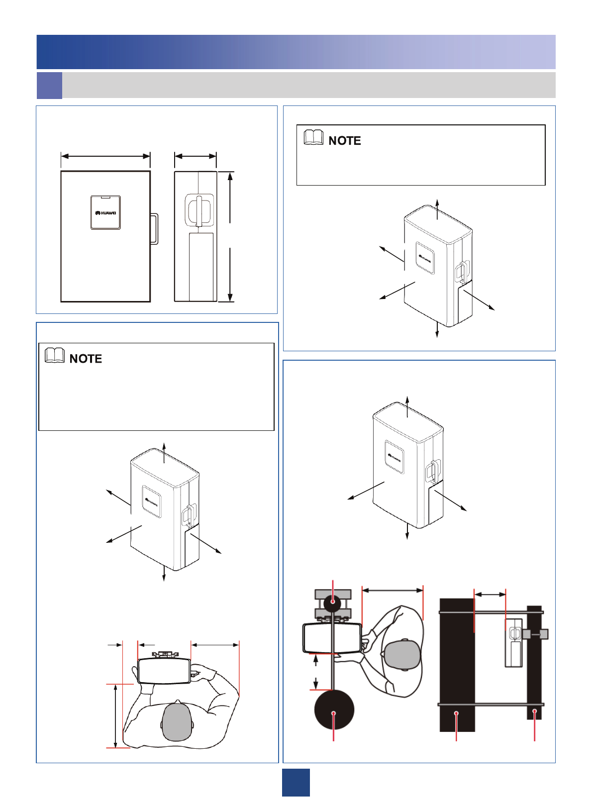
Installing the DC RRU
bDimensions and Installation Clearance
Minimum Clearance for a Single RRU
RRU Dimensions
≥300 mm
≥500 mm
≥800 mm
≥600 mm
≥300 mm
380 mm 170 mm
485 mm
The minimum installation clearance meets the
requirements of the equipment for normal running and
heat dissipation, but does not meet the requirements for
Operation and Maintenance (OM) such as checking the
status of the LEDs and opening the maintenance cavity.
When the installation space is restricted, the minimum
installation clearance can be adopted.
The recommended installation clearance meets the
requirements of the equipment for normal running and OM.
When the installation space is sufficient, the recommended
installation clearance can be adopted.
Minimum clearance for the RRU installed on
a tower
200 mm
300 mm
400 mm
100 mm
600 mm
400 mm
100 mm
600 mm
Top view
200 mm
300 mm
280 mm
400 mm
400 mm 280 mm
Auxiliary metal pole
Main metal pole
Side viewTop view
Main metal
pole
Auxiliary
metal pole
Recommended Clearance for a Single RRU
280 mm
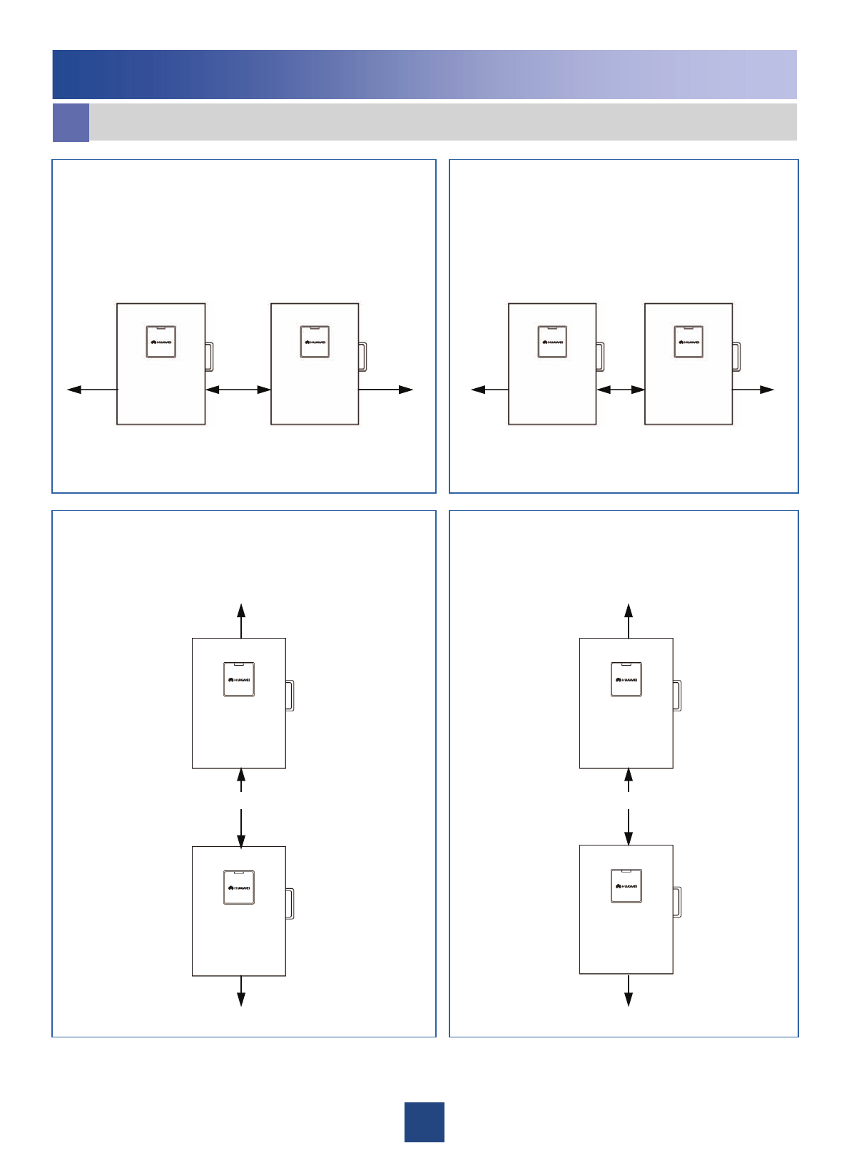
5
≥300 mm ≥600 mm ≥600 mm 100 mm 400 mm 400 mm
≥500 mm
≥500 mm
≥300 mm
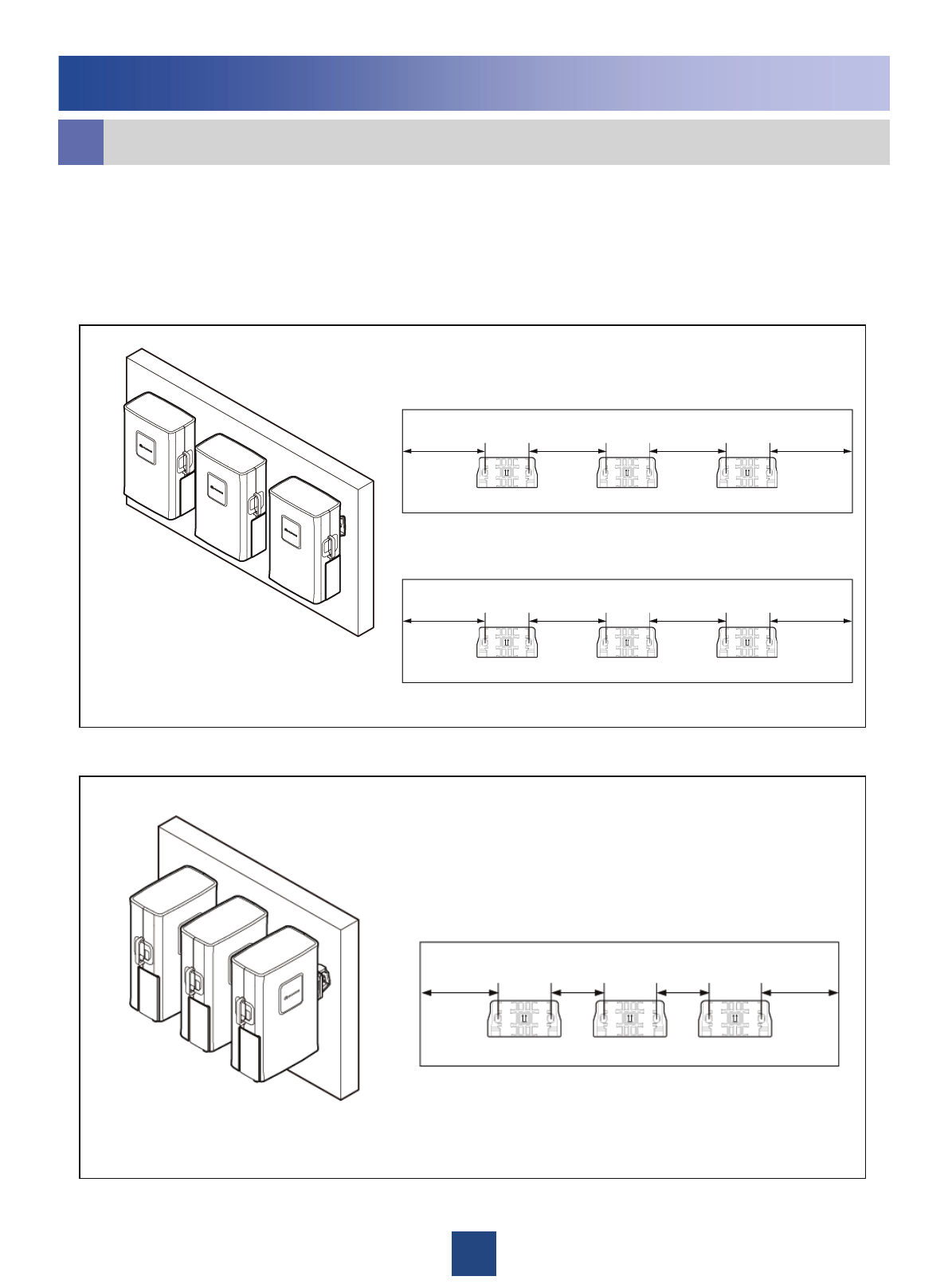
Recommended Horizontal Spacing for
Two RRUs Installed in Parallel Minimum Horizontal Spacing for Two
RRUs Installed in Parallel
Recommended Vertical Spacing for Two
RRUs Installed in Parallel Minimum Vertical Spacing for Two
RRUs Installed in Parallel
Installing the DC RRU
300 mm
300 mm
200 mm
bDimensions and Installation Clearance
6
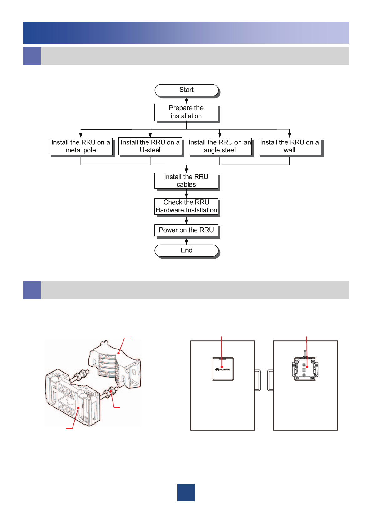
cInstallation Procedure
dPreparing for the Installation
Installing the DC RRU
Dual-nut bolt
Main bracket
Auxiliary bracket
Cover plate Attachment plate
Main and auxiliary brackets for the RRU Front Back
7
1200 mm~1600 mm
40N•m
When installing the
main bracket,
ensure that the
contact piece on
the bracket is fixed.
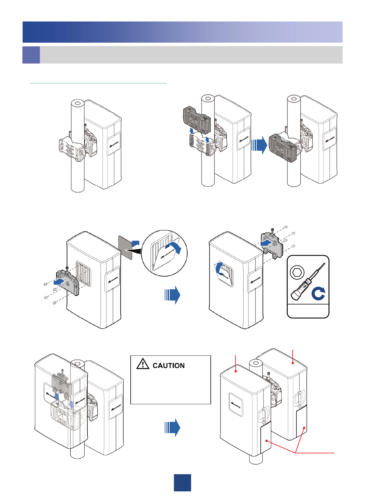
You may fit one end of the auxiliary bracket on one dual-nut bolt assembly and then the other end on the
other dual-nut bolt assembly during the installation.
Fasten the two dual-nut bolt assemblies
alternatively. After the brackets are secure,
use a tape to measure the spacing between
the main bracket and the auxiliary bracket at
the two sides and ensure that the spacing is
the same.
zThe weight-bearing capacity of the RF
ports at the bottom of the RRU is low. Do
not place the RRU at its bottom.
zDuring the operation, place the foam
pad or cardboard under the RRU to
prevent any damage to the housing of
the RRU.
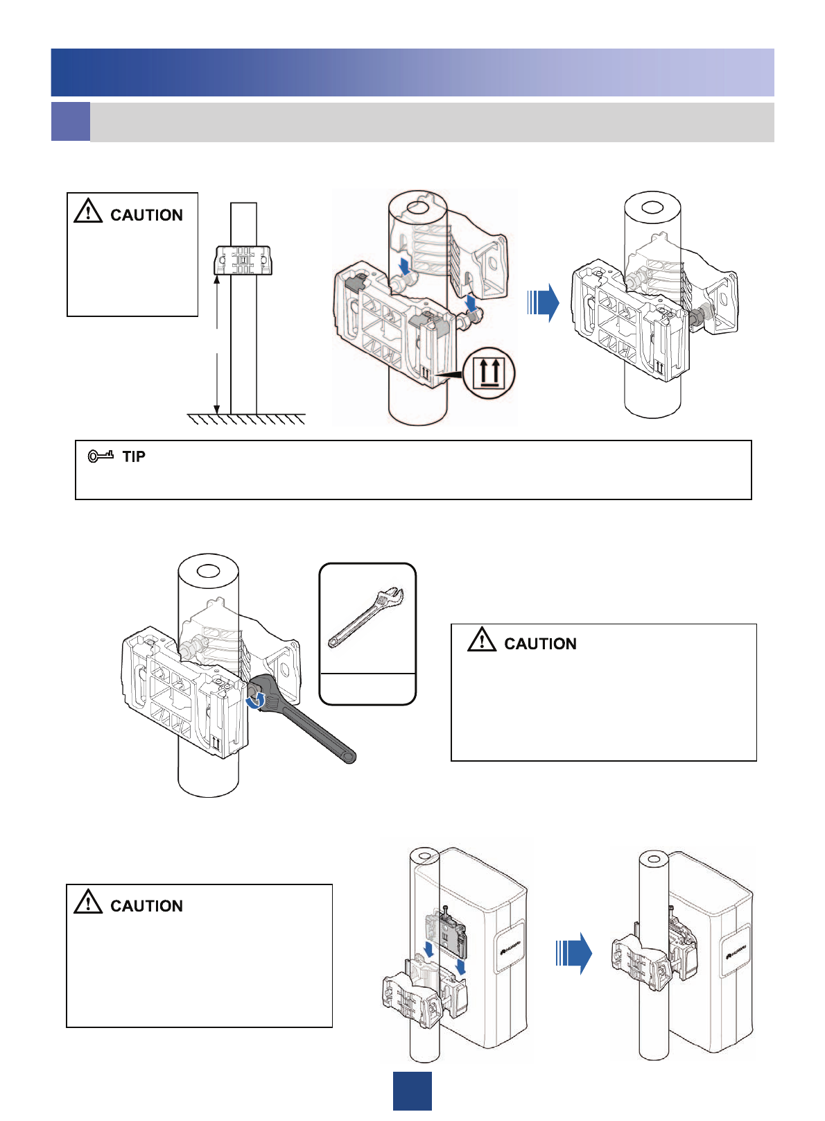
2. Use an adjustable wrench to tighten the nut until the fastening torque is 40 N·m. In
this way, the main and auxiliary brackets are secured on the pole.
1. Install the main bracket.
eInstalling a Single RRU on a Metal Pole
3. Install the RRU on the main bracket. When you hear click sound, you can infer that
the RRU is in position.
Installing the DC RRU
15
Installing the DC RRU
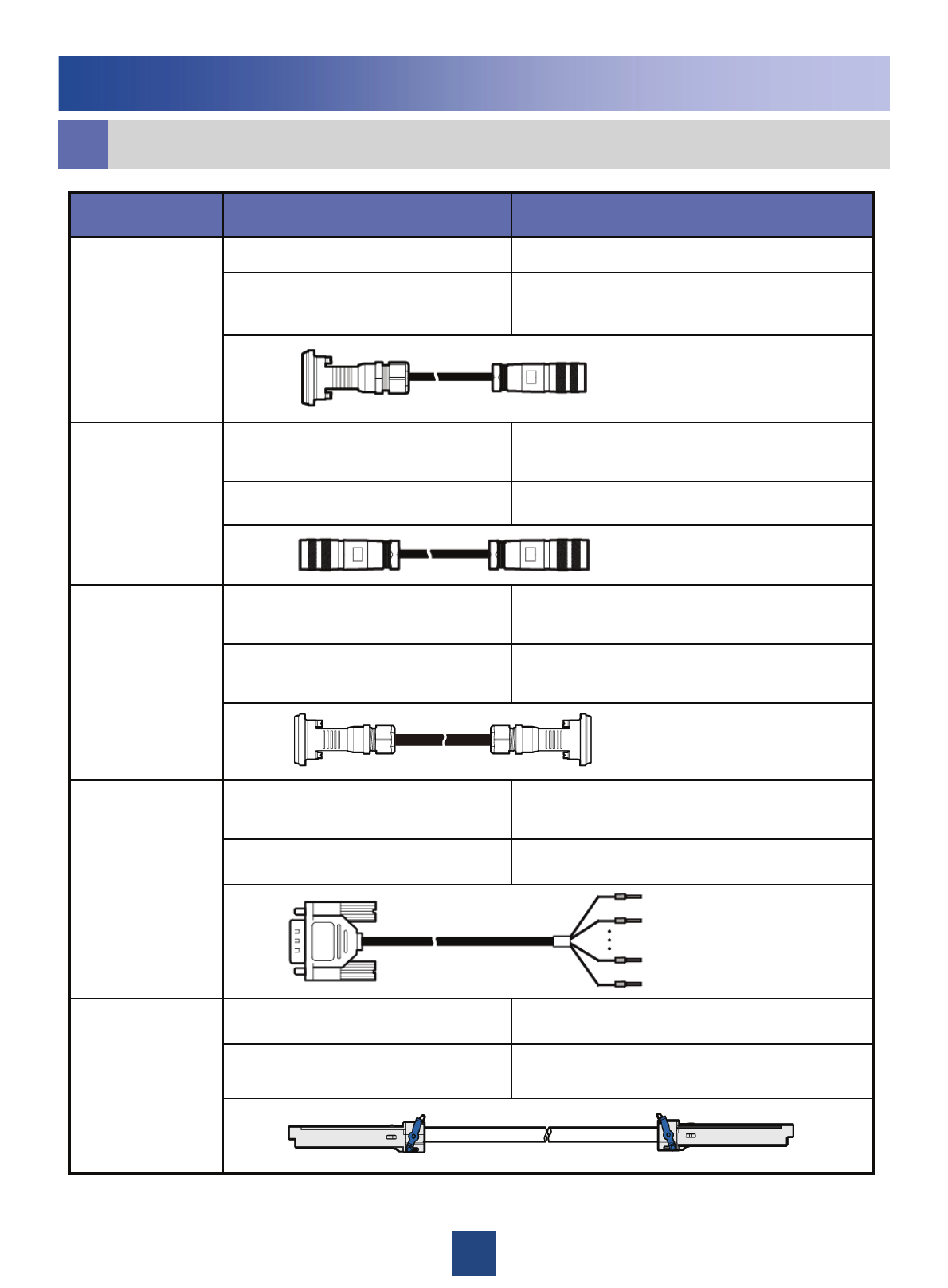
lCable List
External alarm devicesEight cord end terminals
Port labeled EXT_ALM in the RRU cabling
cavity
DB15 male connectorDC RRU alarm
cable
Port labeled RX_IN/OUT on the lower-level
RRU
2W2 connector
Port labeled RX_IN/OUT on the upper-level
RRU
2W2 connectorRF cable between
RRUs
the CPRI_W port on the lower-level RRUSFP200 male connector
the CPRI_E port on the upper-level RRUSFP200 male connectorSFP high-speed
cable for
cascading
Standard AISG male connector of the RCUStandard AISG female connector
Standard AISG female connector of the AISG
multi-wire cable
Standard AISG male connectorAISG extended
cable between the
RRU and the RCU
Standard AISG male connector of the AISG
extension cable or RCU
Standard AISG female connector
Port labeled RET on the RRUWaterproof DB9 connectorAISG multi-wire
cable between the
RRU and the RCU
Connected to…Connector TypeCable
16
Installing the DC RRU
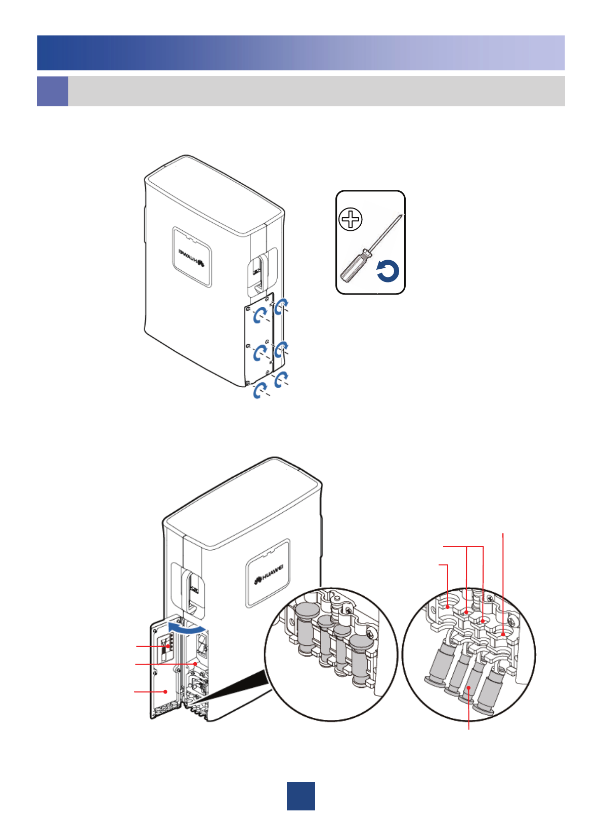
mInstalling the RRU Cables
1. Opening the Cover Plate of the RRU Cabling Cavity
2. The Cabling Cavity of the RRU
Cover plate of
the cabling cavity
Cabling cavity
Reference for making
the power cable
M4
Waterproofing filler
Cable trough for the
power cable
Cable trough for the
optical cable
Cable trough for the
power cable
17
1.4N•m
M4
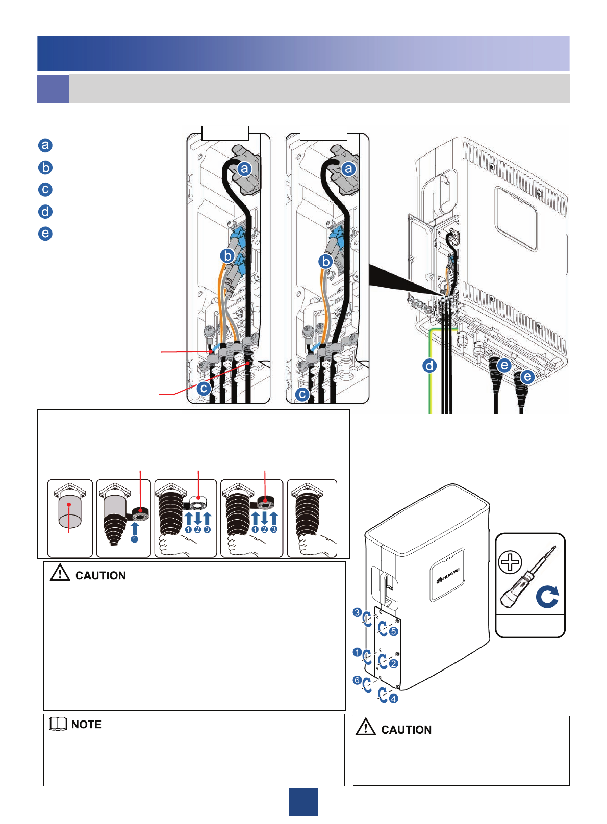
nInstalling the RRU Cables
Installing the DC RRU
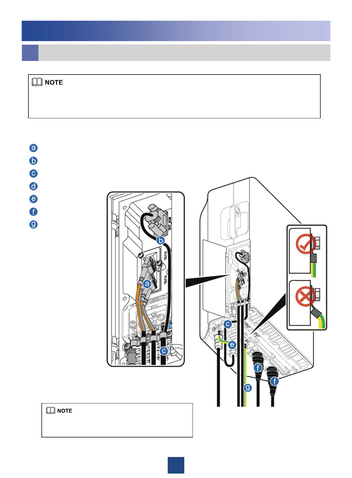
3. Cable Connections of RRU
4. Closing the Cover Plate of
the RRU Cabling Cavity.
zThe screw on the cover plate is tightened until
the fastening torque is 14 kgf•cm.
zThe screws on the cover plate are tightened in
the order shown in the preceding figure.
zThe tape is wrapped spirally upwards, downwards, and then upwards
again in three layers. For every two adjacent tape layers, the tape on the
upper layer overlaps about half the width of the tape on the lower layer.
zFor details on how to add the OT terminals to the DC RRU power
cable, see page 36.
zPress the strap on the exposed shielding layer of the power cable
tightly. Ensure that the lower edge of the exposed shield layer does not
exceed the position shown in the figure.
zThe alarm cable is preferably led out of the RRU from the narrower
cable trough in the middle of the cabling cavity. If the cable trough is
used by the CPRI optical cable, the alarm cable is led from the wider
cable trough near the middle one. In this case, the alarm cable must be
wrapped with 10 to 17 layers of waterproof tape so that the diameter of
the cable reaches 10 mm to 12 mm.
zTo avoid sharp bending, the optical cable must be pressed by the
strap next to the power cable during the optical cable installation.
zWaterproof fillers should be installed in the unused cable trough.
Waterproofed
alarm cable
Shielding layer of
the power cable
DC RRU alarm cable
CPRI optical cable
DC RRU power cable
PGND cable
RRU RF jumper
Case 2 Case 1
Do not remove the dustproof cap from the feeder connectors that are not
in use. In addition, protection measures against damp, dust, and salt mist
must be taken. If the RRU is installed outdoors, you also need to wrap
the joint with waterproof tape, as shown in the following figures.
Waterproof tape
Dustproof
cap
Insulating tapeInsulating tape
18
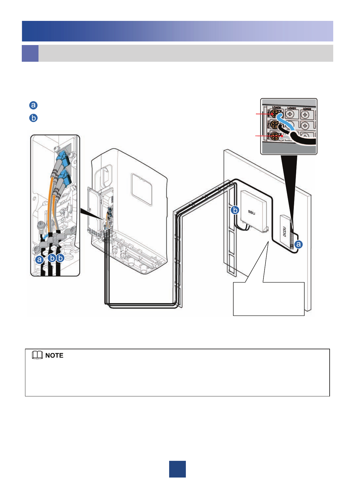
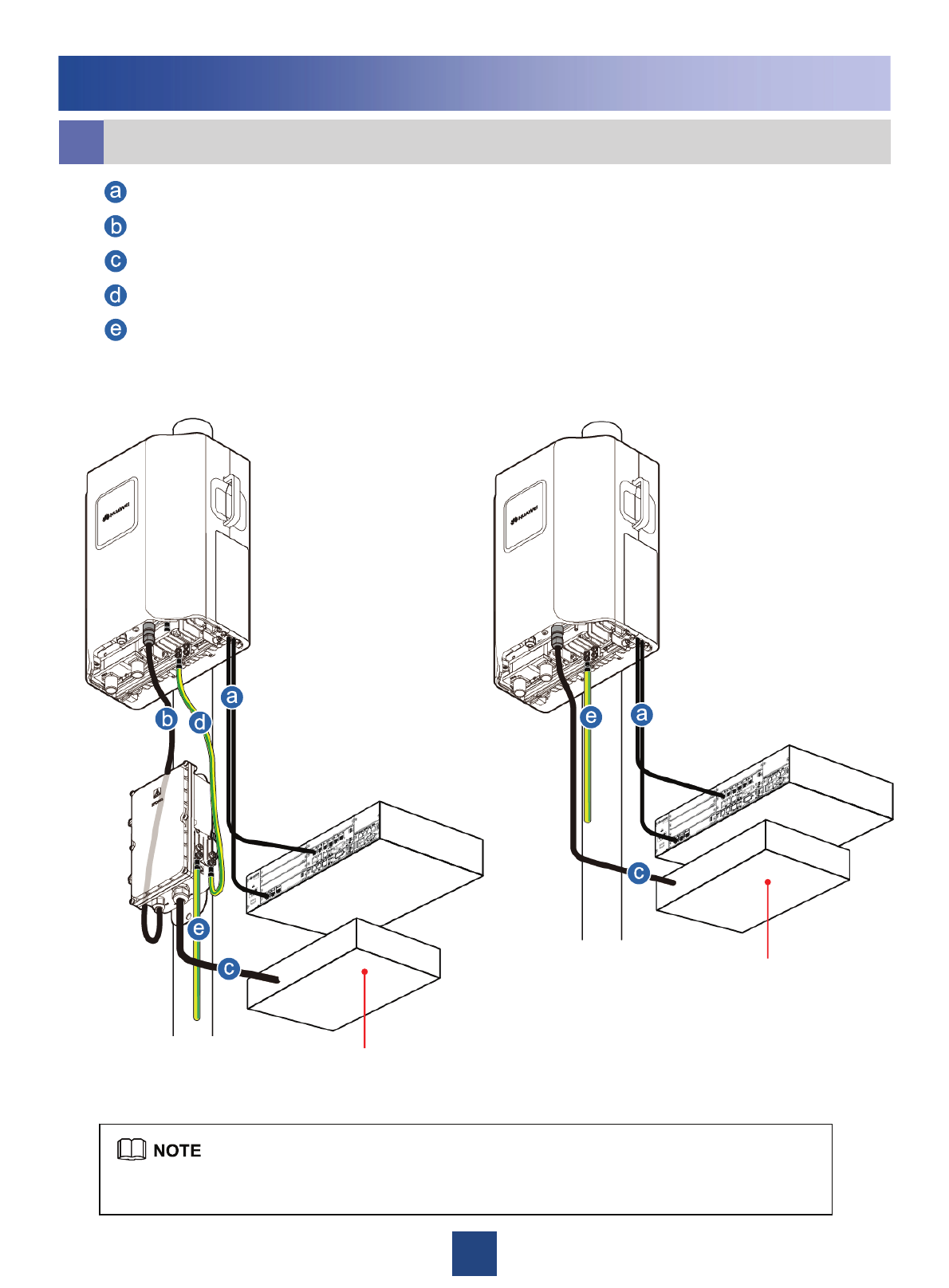
RRU+Wall-Mounted BBU
oRRU Cable Installation Scenarios
Installing the DC RRU
DC RRU power cable
CPRI optical cable
The DCDU panel must
face right side and the
BBU panel must face
downwards.
LOAD0
Shielding layer
of DC RRU
power cable
zWhen connecting the DC RRU power cable to the DCDU-03B, you must add an OT terminal to the
shielding layer. Then, fix the OT terminal to the corresponding PGND terminal of the DCDU-03B. For
details on how to add an OT terminal, see page 37.
zThe DC RRU power cable is connected to one of the LOAD0 to LOAD5 terminals of the DCDU-03B.
19
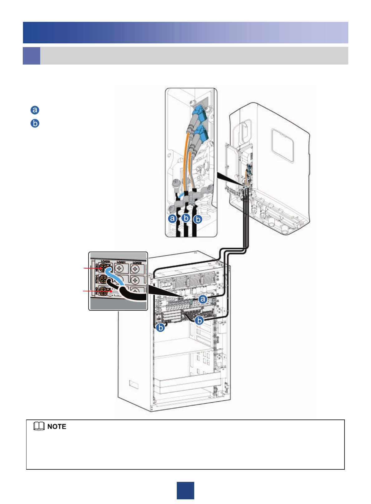
LOAD0
RRU+PS4890
Installing the DC RRU
Shielding layer
of DC RRU
power cable
DC RRU power cable
CPRI optical cable
oRRU Cable Installation Scenarios
zWhen connecting the DC RRU power cable to the DCDU-03B, you must add an OT terminal to the
shielding layer. Then, fix the OT terminal to the corresponding PGND terminal of the DCDU-03B. For
details on how to add an OT terminal, see page 37.
zThe DC RRU power cable is connected to one of the LOAD0 to LOAD5 terminals of the DCDU-03B.
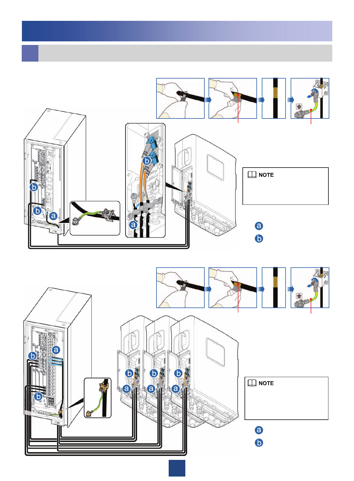
20
The DC RRU power cable is
connected to terminals of the
4815 power system for RRU.
Installing the DC RRU
oRRU Cable Installation Scenarios
220 V AC input (4815 installed in the OMB cabinet).
–48 V DC input (DCDU-03C installed in the OMB cabinet).
The DC RRU power cable
is connected to one of the
LOAD0 to LOAD5 terminals
of the DCDU-03B.
Metal Shielding layer (25 mm) PGND cable
Grounding the shielding layer
of the power cable:
Metal Shielding layer (25 mm) PGND cable
Grounding the shielding layer
of the power cable:
DC RRU power cable
CPRI optical cable
DC RRU power cable
CPRI optical cable
8
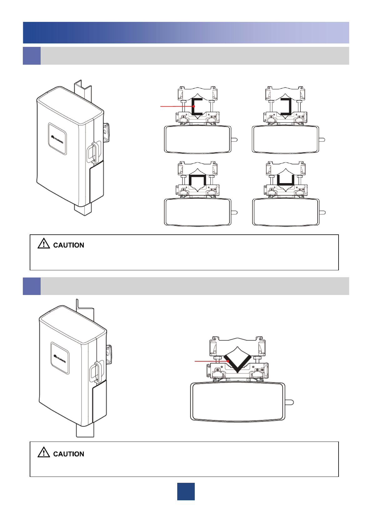
Cabling cavity
In standard mode In reverse mode
Installing Two RRUs Back-To-Back on a Metal Pole
f
4. Install the second RRU on the main bracket.
3. Reinstall the attachment plate and cover plate on the second RRU by interchanging
their positions.
1. Install an RRU. For details, see page 6
Installing a Single RRU on a Metal Pole.2. Install the main fixture for another RRU.
Ensure that the cabling
cavities of the two RRUs
face the same direction
when installing the RRUs.
5N•m
M6X16
Installing the DC RRU
9
gInstalling the RRU on a U-Steel
hInstalling the RRU on an Angle Steel
Installing the DC RRU
zThe procedure for installing the RRU on a U-steel is the same as that on a metal pole.
zOnly one RRU can be installed on a U-steel.
zThe procedure for installing the RRU on an angle steel is the same as that on a metal pole.
zOnly one RRU can be installed on an angle steel.
U-steel
Plan view
Plan view
Angle steel
10
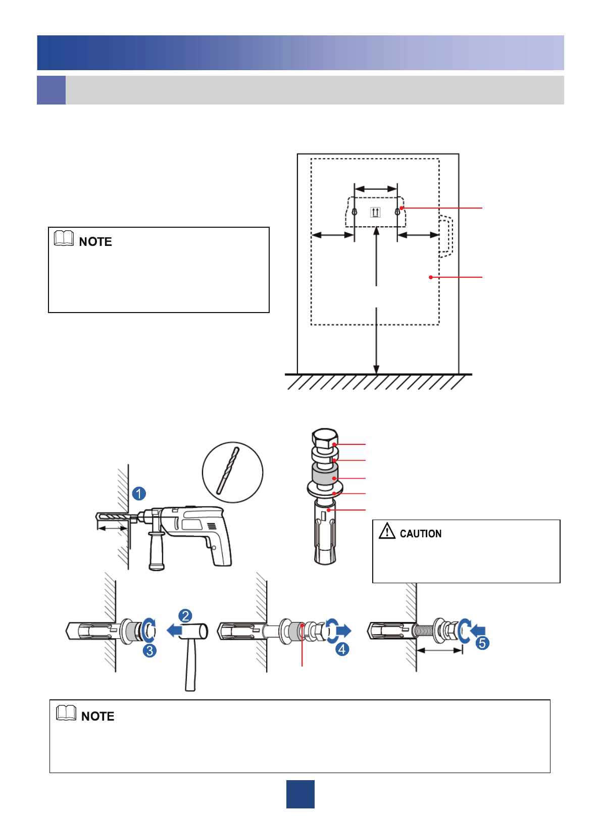
Ø14
After the expansion bolt is removed,
dispose of the plastic tube.
90°
55 mm to 60 mm
20 mm to 30 mm
M10x65 bolt
Spring washer 10
Plastic tube
Flat washer 10
Expansion tube
Do not hammer the bolt entirely into the
wall. Instead, leave 20 mm to 30 mm of
the bolt outside the wall.
iInstalling the RRU on a Wall
Installing the DC RRU
2. Drill holes at the anchor points and then install the expansion bolt assemblies.
When the RRU is installed on a wall, the requirements are as follows:
zFor one RRU, the wall has a weight-bearing capacity of 92 kg.
zThe fastening torque of the expansion bolt reaches 30 N·m, the expansion bolt works properly, and no
damages such as cracks are on the wall.
1. Place the auxiliary fixture on the wall at the installation position and then mark the
anchor points by using a marking pen.
zIt is recommended that the auxiliary bracket
be 1,200 mm to 1,600 mm above the ground.
zThe RRUs cannot installed on a wall in
centralized mode. Therefore, expansion bolt
assemblies should be prepared for each RRU. 1200 mm~1600 mm
128 mm
126 mm
Auxiliary bracket
126 mm
RRU
11
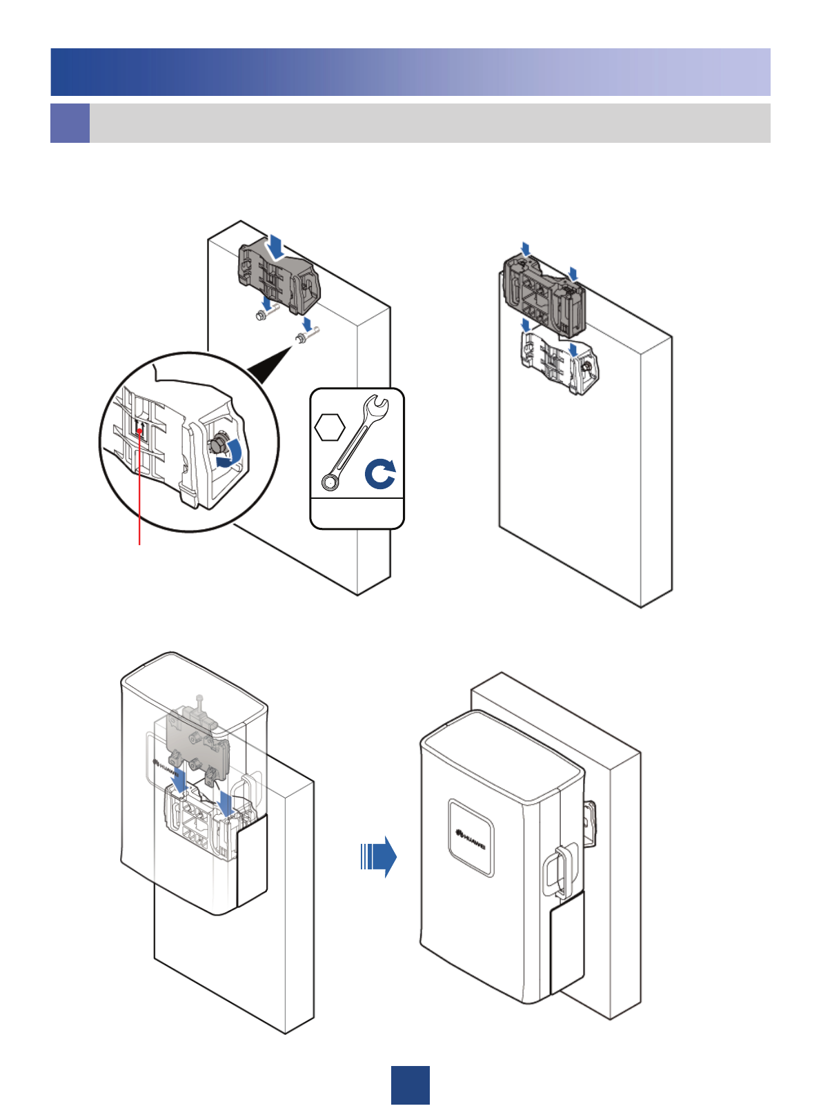
iInstalling the RRU on a Wall
Installing the DC RRU
Arrows are upwards
30N•m
M10
3. Fit the auxiliary bracket on the expansion
bolts downward, and then tighten the bolts
by using a combination wrench 17 mm.
4. Install the main bracket.
5. Install the RRU.
12
6. Install multiple RRUs.
≥70 mm ≥70 mm
650 mm
Minimum Clearance:
Recommended Clearance :
≥760 mm ≥760 mm
iInstalling the RRU on a Wall
Installing the DC RRU
≥730 mm≥430 mm
650 mm 530 mm230 mm
≥535 mm ≥535 mm
13
When a dual-polarized antenna is shared by two RRUs in the same sector, the two RRUs are connected
through an RF cable between RFUs. The connections of three RRUs in the same sector are not supported.
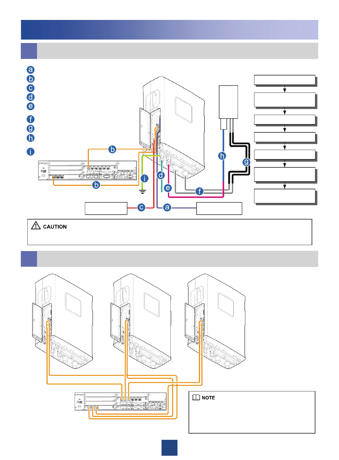
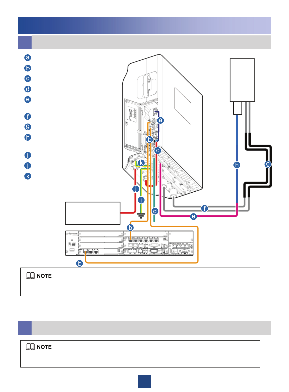
jCable Connections of a Single RRU
kCable Connections of Multiple RRUs
Installing the DC RRU
This figure shows only the CPRI optical cable
connections. For details on the connections
of other cables, see the cable connections
for a single RRU.
External alarm
device
External power
supply
RCU
DC RRU alarm cable
CPRI optical cable
DC RRU power cable
RF cable between RFUs
AISG multi-wire cable between
the RRU and the RCU
RRU RF jumper
Feeder
AISG extended cable between
the RRU and the RCU
PGND cable
Antenna
Install the PGND cable
Install the RF jumper
(RF cable between RFUs is
optional)
Install the DC RRU power cable
Install the CPRI optical cable
Install the DC RRU alarm
cable(optional)
Install the AISG multi-wire cable
between the RRU and the RCU
(optional)
Install the AISG multi-wire cable
between the RRU and the RCU
(optional)
14
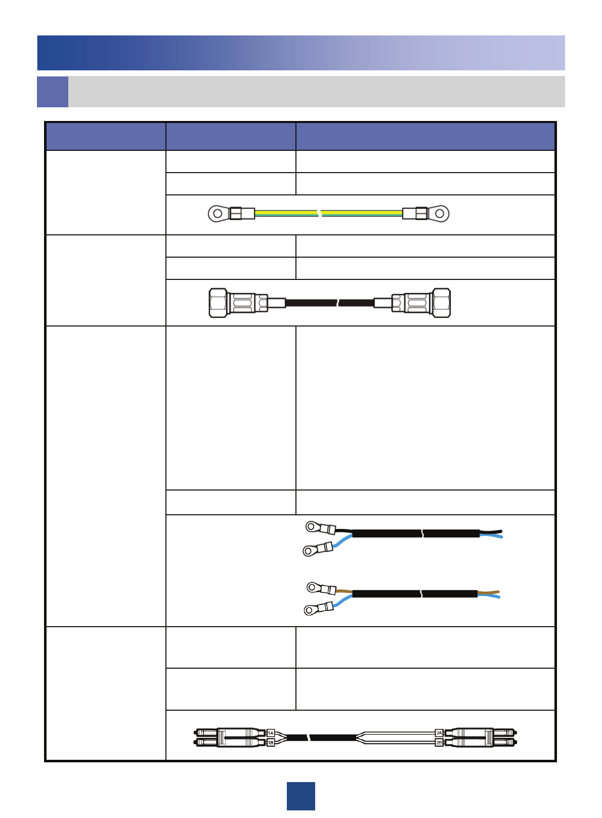
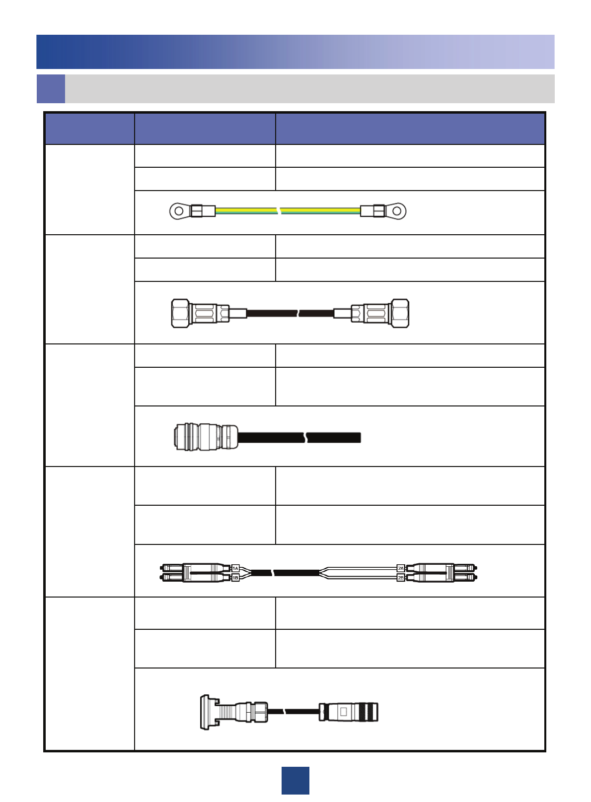
lCable List
Installing the DC RRU
Connect the fiber tails labeled 1A and 1B to the
CPRI_W port on the RRU
DLC connectorCPRI optical cable
Connect the fiber tails labeled 2A and 2B to one of the
CPRI0 to CPRI5 ports on the WBBP or GTMU
DLC connector
zNorth American standard:
The OT terminal on the blue wire is connected to the
NEG(-) port on the cabling cavity of the RRU. The OT
terminal on the black wire is connected to the RTN(+)
port on the cabling cavity of the RRU
zEuropean standard:
The OT terminal on the blue wire is connected to the
NEG(-) port on the cabling cavity of the RRU. The OT
terminal on the brown wire is connected to the RTN(+)
port on the cabling cavity of the RRU
Two OT terminals ( M4 )DC RRU power cable
( North American
standard: 2AWG
European standard:
4 mm² )
External power supplyBare wire
Feeder or antennaDIN male connector
Ports labeled ANT-A and ANT-B on the RRUDIN male connectorRRU RF jumper
Nearest grounding barOT terminal ( M8 )
Grounding bolt on the RRUOT terminal ( M6 )PGND cable
(16 mm²)
Connected to…Connector TypeCable
North American standard:
European standard:
North American standard:
European standard:
22
RRU+TMC
Installing the DC RRU
DC RRU power cable
CPRI optical cable
oRRU Cable Installation Scenarios
Metal Shielding layer (25 mm) PGND cable
Grounding the shielding layer
of the power cable:
zWhen connecting the DC RRU power cable to the DCDU-03B, you must add an OT terminal to the shielding
layer. Then, fix the OT terminal to the corresponding PGND terminal of the DCDU-03B. For details on how to
add an OT terminal, see page 37.
zThe DC RRU power cable is connected to one of the LOAD0 to LOAD5 terminals of the DCDU-03B.
zThree power cables can be led through each ground clip.
23
Space Requirements
a
bInstallation Modes
b
Installing the AC RRU
The AC RRU cannot be installed at the side. When it is installed in other modes, the procedure is the same as
that of the DC RRU.
For details, see page 6.
380 mm 250 mm
485 mm
On a metal pole On a wall
On an angle steelOn a U-steel
The recommended/minimal clearance for the
AC RRU/clearance for Two Combined RRUs is
the same as that for the DC RRU. For details,
see page 4 and page 5.
24
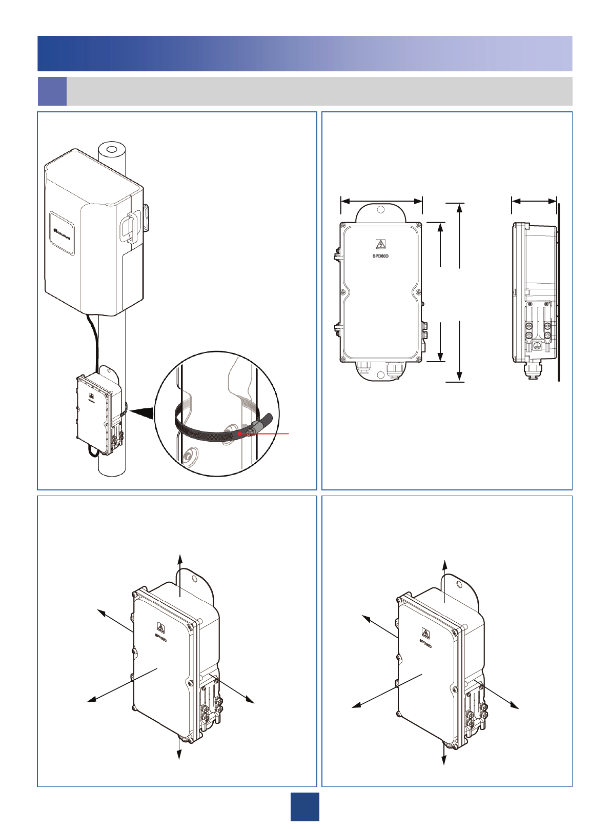
Installing the Surge Protection Box (for Outdoor Scenarios)
c
Dimensions of the surge protection
box.
Recommended clearance for the surge
protection box.
Installation of the surge protection box.
Installing the AC RRU
Hoop
iron
140 mm
240 mm
305 mm
75 mm
≥100 mm
≥500 mm
≥500 mm
≥500 mm
≥100 mm
50 mm
300 mm
300 mm
300 mm
50 mm
Minimal clearance for the surge
protection box.
25
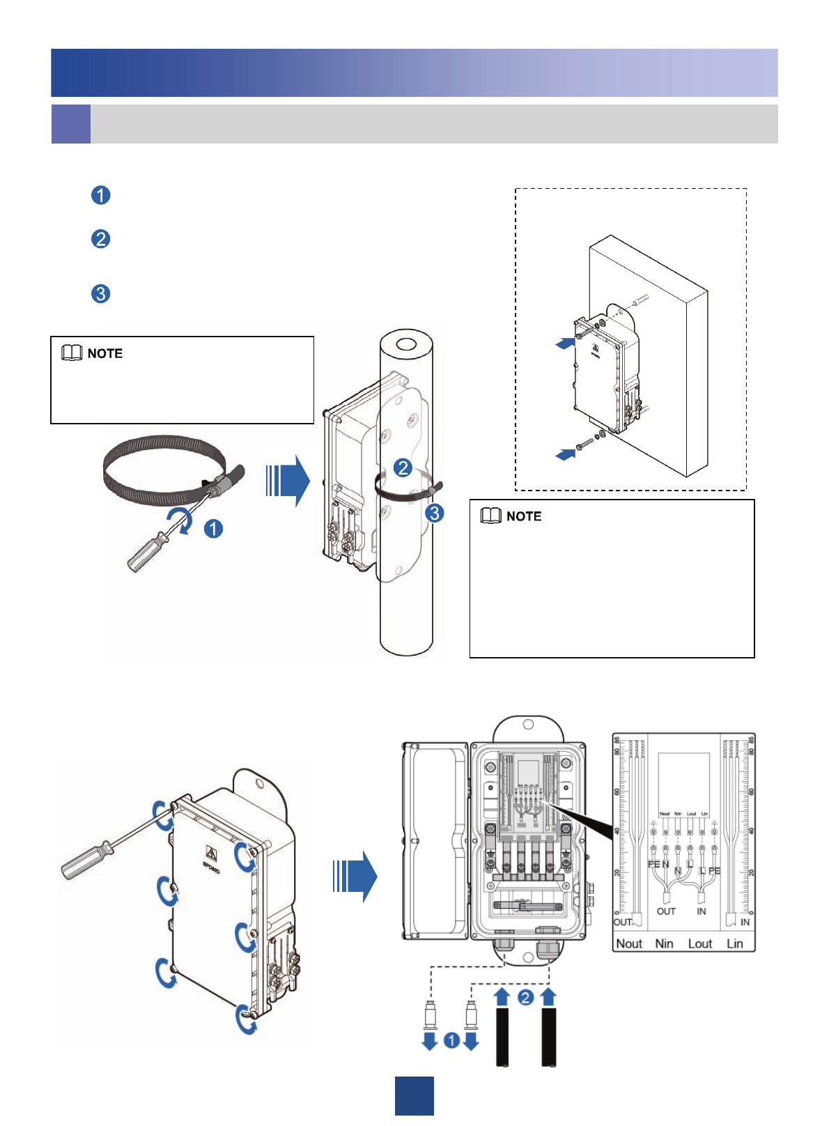
2. Open the cover of the surge protection box.
1. Install the surge protection box on the metal pole.
As shown in the figure, unfasten the screw on
the loop iron with the torque of 4.8 N•m.
Lead the loop iron through the opening
between the back plate of the surge protection
box and the surge protection box.
Circle the loop iron around the metal pole, and
then tighten the screw on the loop iron.
Installing the surge protection
box on the wall
Installing the AC RRU
Installing the Surge Protection Box (for Outdoor Scenarios)
c
If the pole has a small diameter, there
is a long extra part of the hoop. It is
recommended that the extra part be cut.
zwhen installing the surge protection box,
you need to dispose of the plastic tube on
the expansion bolt.
zThe procedure for installing the surge
protection box on the wall is the same as
that for installing the RRU on the wall. For
details, see page 10.
26
Installing the AC RRU
Installing the Surge Protection Box (for Outdoor Scenarios)
c
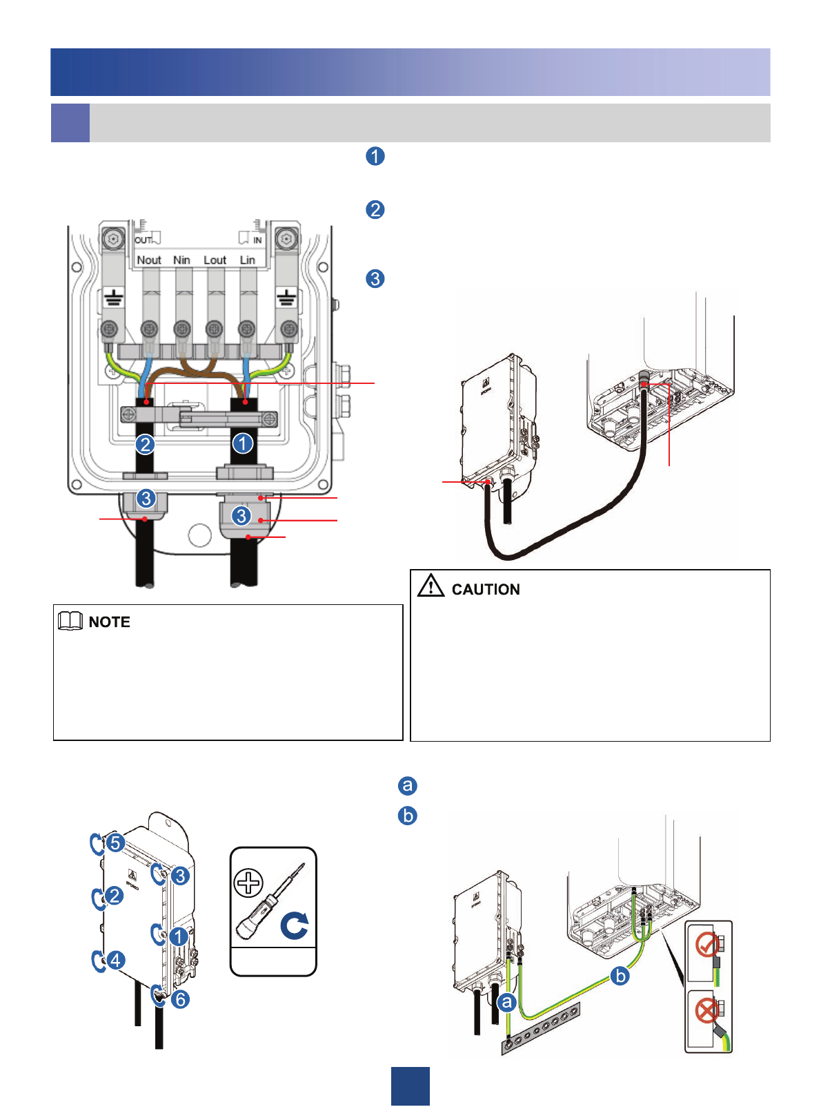
OUT AC IN
IN
OUT
1.4N•m
PG connector
Thread-lock
sealing nut
Lead the external AC power cable through the PG connector labeled
IN. The L, N, and PE wires of the power cable are connected to the
Lin, Nin, and PE terminals on the surge protection box.
Lead the power cable between the RRU and the surge protection
box through the PG connector labeled OUT. The Lin, Nin, and PE
wires of the power cable are connected to the Lout, Nout, and PE
terminals on the surge protection box.
Tighten the thread-lock sealing nut, and then use a wrench to further
tighten the connector for one or two laps to ensure its waterproofing
capability.
3. Connect the power cable
between the surge protection
box and the RRU.
5. Connect the PGND cable.
zThe cable led through the PG connector labeled OUT is the
power cable between the RRU and the surge protection box,
and the cable led through the PG connector labeled IN is the
external AC power cable.
zInstall the corrugated pipes for the AC power cables before
installing the AC RRU power cables. For details, see page 39.
zLead the cable through the removed thread-lock sealing nut
of the PG connector, and then lead the cable through the PG
connector.
zThe removed thread-lock sealing nut of the PG connector
cannot be replaced with the thread-lock sealing nuts of other
surge protection boxes.
zEnsure that the case of the cable insulating layer is tightly
pressed by the strap.
4. Close the cover of the surge
protection box. PGND cable
Equipotential cable
Insulating
layer
27
Cable Connections of a Single RRU
d
Installing the AC RRU
Cable Connections of Multiple RRUs
e
The cable connections for multiple AC-powered RRUs and multiple DC-powered RRUs are the same. For
details, see page13.
The AC RRU monitoring signal cable, DC RRU power cable, equipotential cable between the power module
and the RRU are installed before delivery.
Sequence of Installing the Cables:PGND cable →RRU RF jumper →AC RRU power cable→CPRI optical
cable →AISG multi-wire cable between the RRU and the RCU ( optional ) →AISG extended cable between
the RRU and the RCU ( optional )
Antenna
AC RRU monitoring signal cable
CPRI optical cable
DC RRU power cable
RF cable between RRUs
AISG multi-wire cable between
the RRU and the RCU
RRU RF jumper
Feeder
AISG extended cable between
the RRU and the RCU
PGND cable
AC RRU power cable
Equipotential cable
External power
supply
28
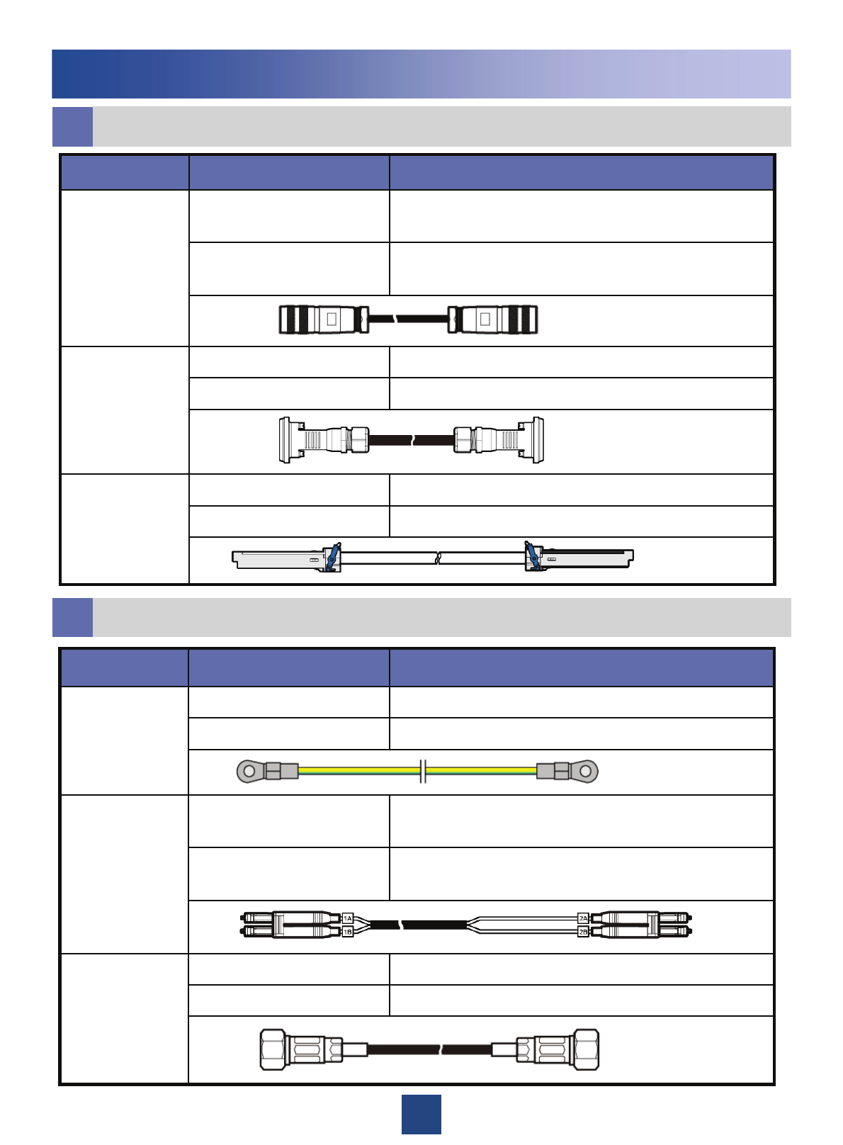
List of Cables (No Surge Protection Box Configured)
f
Installing the AC RRU
Ports labeled ANT-A and ANT-B on the RRUDIN male connector
RRU RF jumper
Feeder or antennaDIN male connector
Port labeled AC_in on the RRURound connector
AC RRU power
cable
(1.5mm²)External power supply
To be made depending on
field requirements
Connect the fiber tails labeled 1A and 1B to the CPRI_W
port on the RRU
DLC connectorCPRI optical
cable
Connect the fiber tails labeled 2A and 2B to one of the
CPRI0 to CPRI5 ports on the WBBP or GTMU
DLC connector
Port labeled RET on the RRUWaterproof DB9 connectorAISG multi-wire
cable between
the RRU and the
RCU
Standard AISG male connector of the AISG extension
cable or RCU
Standard AISG female
connector
Nearest grounding barOT terminal (M8)
Grounding bolt on the RRUOT terminal (M6)PGND cable
(16 mm²)
Connected to…Connector TypeCable
29
List of Cables (No Surge Protection Box Configured)
f
Installing the AC RRU
the CPRI_E port on the upper-level RRUSFP200 male connectorSFP high-speed
cable for
cascaded RRUs the CPRI_W port on the lower-level RRUSFP200 male connector
Standard AISG female connector of the AISG multi-wire
cable
Standard AISG male
connector
AISG extended
cable between
the RRU and the
RCU Standard AISG male connector of the RCUStandard AISG female
connector
Port labeled RX_IN/OUT on the RRU2W2 connectorRF cable
between RRUs Port labeled RX_IN/OUT on the RRU2W2 connector
Connected to…Connector TypeCable
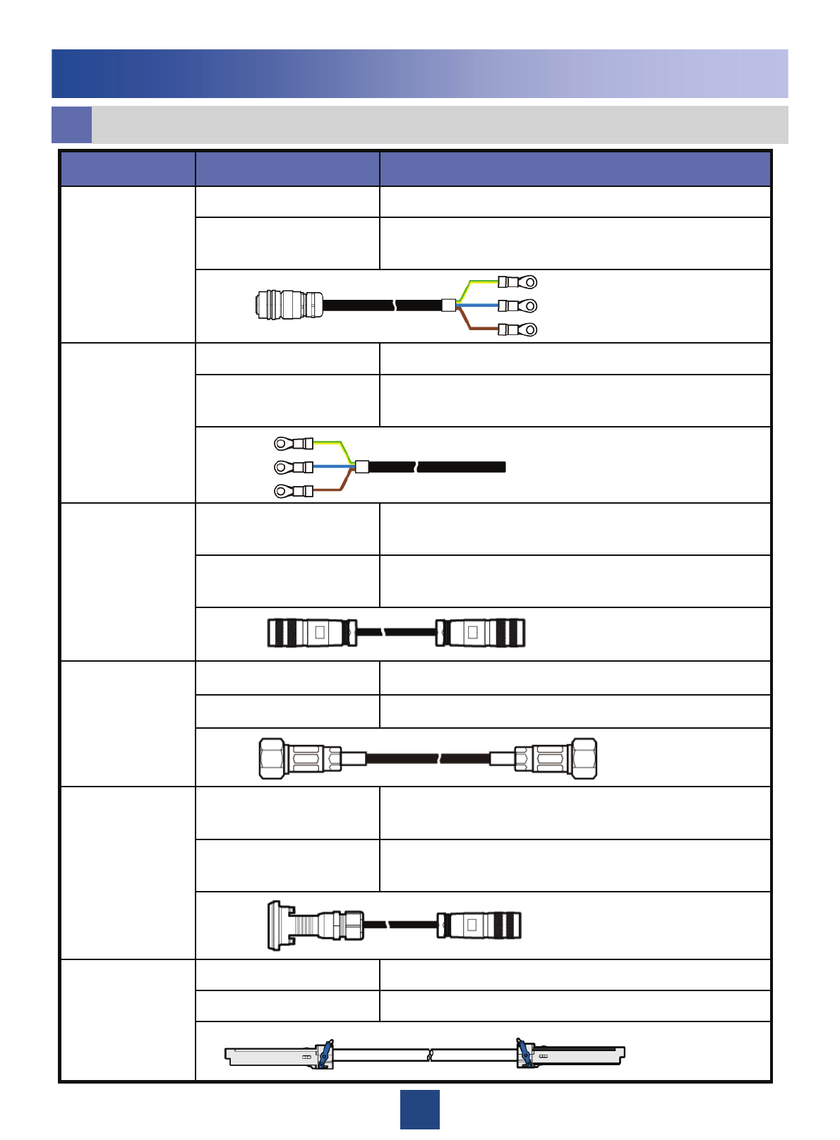
List of Cables (Surge protection box Configured)
g
Connect the fiber tails labeled 2A and 2B to one of the
CPRI0 to CPRI5 ports on the GTMU
DLC connector
Connect the fiber tails labeled 1A and 1B to the CPRI_W
port on the RRU
DLC connectorCPRI optical
cable
Connected to…Connector TypeCable
Feeder or antennaDIN male connector
Ports labeled ANT-A and ANT-B on the RRUDIN male connector
RRU RF jumper
Nearest grounding barOT terminal (M8)
Grounding bolt on the surge protection boxOT terminal (M6)PGND cable
(16 mm²)
30
List of Cables (Surge protection box Configured)
g
Installing the AC RRU
the CPRI_W port on the upper-level RRUSFP200 male connectorSFP high-speed
cable for
cascaded RRUs the CPRI_E port on the lower-level RRUSFP200 male connector
Port labeled RET/PWR_SRXU on the RRUWaterproof DB9
connector
AISG multi-wire
cable between the
RRU and the
RCU Standard AISG male connector of the AISG extension
cable or RCU
Standard AISG female
connector
Standard AISG female connector of the AISG multi-wire
cable
Standard AISG male
connector
AISG extended
cable between the
RRU and the
RCU Standard AISG male connector of the RCUStandard AISG female
connector
The Lin, Nin, and PE terminals on the surge protection box OT terminal
External AC input
power cable
(4 mm²) External power supply
To be made depending on
field requirements
Port labeled RX_IN/OUT on the lower-level RRU2W2 connector
Port labeled RX_IN/OUT on the upper-level RRU2W2 connectorRF cable between
RRUs
Port labeled AC IN on the RRURound connectorPower cable
between RRU and
the surge
protection box
(1.5 mm²)
The Lout, Nout, and PE terminals on the surge protection
box
OT terminal
Connected to…Connector TypeCable
31
hInstalling the RRU Cables
The cabling cavity of the AC RRU is the same as that of the DC RRU.
The procedures for opening and closing the cover for the cabling cavity of the AC RRU are the same as
those for opening and closing the cover for the cabling cavity of the DC RRU.
Installing the AC RRU
Cable Connections of RRU
CPRI optical cable
AC RRU monitoring signal cable
DC RRU power cable
AC RRU power cable
Equipotential cable
RRU RF jumper
PGND cable
Wrap the RF jumper for the RRU with the waterproof
tape, and then wrap it with the PVC insulating tape.
32
Installing the AC RRU
The maximum length of the external AC input power cable is 70 m for the 110 V AC single-phase
power cable and 100m for the 220 V AC single-phase power cable.
zfor Outdoor Scenarios zfor Indoor Scenarios
External power
supply system
External power
supply system
hInstalling the RRU Cables
CPRI optical cable
Power cable between RRU and the surge protection box
External AC input power cable
Equipotential cable
PGND cable

33
Installing the AC RRU
Installation Checklist
i
3. The OT terminals of the cables connected to the surge protection box are securely
linked. The jackets of the cables are not damaged, and there are no uneven edges on the
cables.
2. The waterproof gaskets on the door of the cabling cavity of the surge protection box are
not stripped or broken.
1. The PG connectors labeled IN and OUT on the surge protection box are securely
installed and cannot be rotated with the cables.
5. The six screws on the cabling cavity of the surge protection are tightened according to
the required fastening torque.
4. The PG connectors are tightened, and the waterproof rings are secure.
9. The installation and maintenance of the surge protection box is not performed in rainy
or damp weather.
8. The power supply to the surge protection box is cut off before installation and
maintenance.
7. The cables in the surge protection box are correctly connected by referring to the
operation guide. The OT terminals are tight linked before the door of the cabling cavity is
closed.
6. The axis for the door of the cabling cavity of the surge protection box is not broken, and
the surface of the protection box is not scratched.
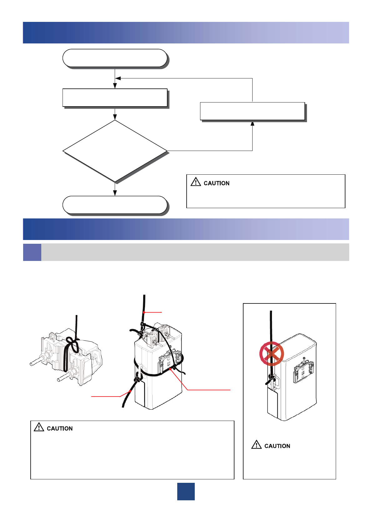
34
Start
End
Power on the RRU
Check whether
the status of the RUN LED
is 1s ON, 1s OFF and that of
ALM LED is OFF.
Rectify the fault
Yes
No
Powering On the RRU
Appendix
aBinding the RRU and Installation Components
1. Bind the RRU by leading the lifting rope along the lower part of the adapting piece
and through the handle, bind the main and auxiliary brackets with the lifting rope, and
then bind the steering rope with the handle of the RRU, as shown in the following
figures.
Lifting rope
Lower part of the
adapting piece
Steering
rope
Do not bind the lifting rope
only on the handle when
lifting the RRU.
zWhen lifting the RRU and installation components to the tower,
prevent the RRU from colliding with the tower.
zThe cross-sectional area of the lifting rope and steering rope is
around 20 mm, not more than 25 mm. In addition, the ropes can bear
the weight four times more than that of the RRU.
When the RRU is unpacked, it must be powered on
within 24 hours.
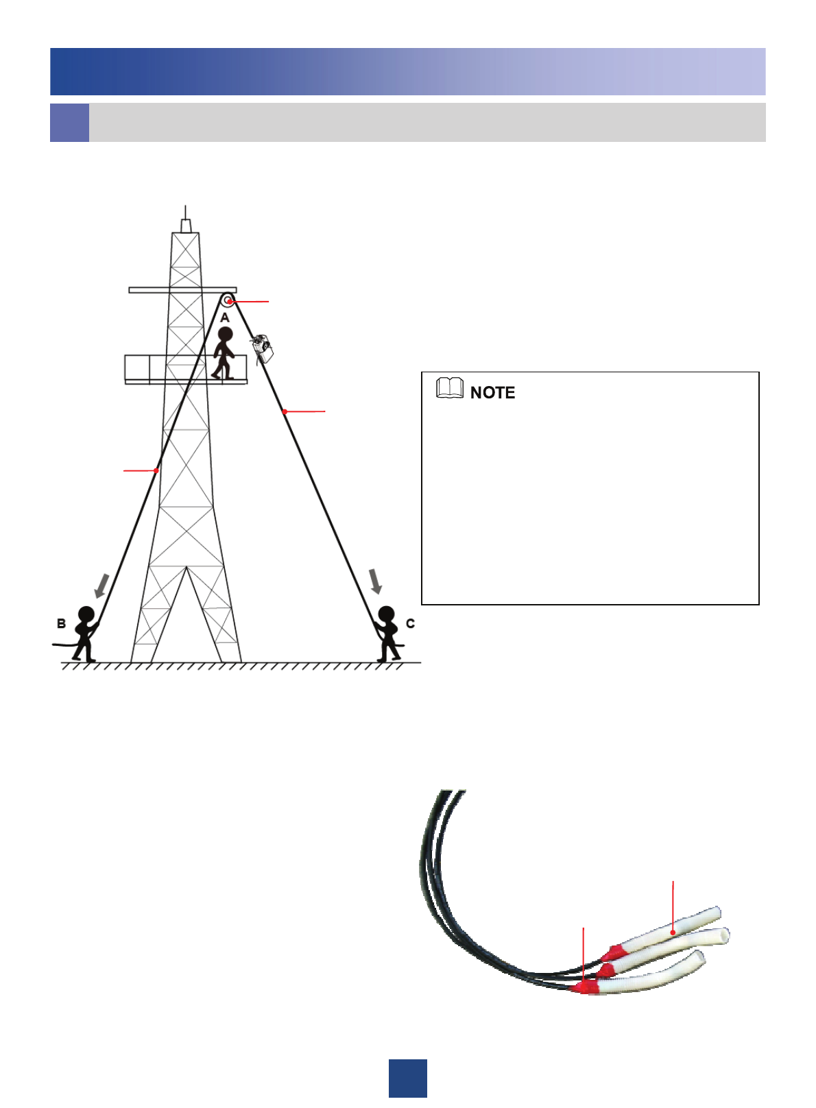
35
zInstaller A climbs onto the tower. Then, installer
A fixes the pulley to the support of the tower
platform and leads the lifting rope through the
pulley.
zInstaller C uses a lifting rope to bind the RRU
and installation components as shown in the
preceding figure and then ties a knot in the steering
rope at the handle of the RRU.
zInstaller B pulls the lifting rope, and at the same
time, installer C pulls the steering rope away from
the tower to prevent the RRU and installation
components from colliding with the tower.
zInstaller A holds the RRU and installation
components and untie the ropes.
Steering rope
Lifting rope
Pulley
Appendix
zCut off a 200 mm long corrugated pipe with the
diameter of 25 mm.
zLead the fiber tails labeled 1A and 1B of the
optical cable into the corrugated pipe by 160 mm.
zWrap up the corrugated pipe and optical cable
with the color tape.
zFor the tower made of steel pipes, tie the black
jacket to the corrugated pipe at the position 150 mm
away from the color tape, and then lift the optical
cable up to the tower.
zFor the tower made of angle steel girders, carry
the optical cable onto the tower when climbing up to
the tower.
zAfter the optical cable is lifted up to the tower,
remove the color tape and corrugated pipe before
installing the optical cable.
3. Lifting the CPRI Optical Cable up to the Tower
Binding the RRU and Installation Components
a
2. Lifting the RRU and Installation Components to the Tower
Color tape
Corrugated pipe
36
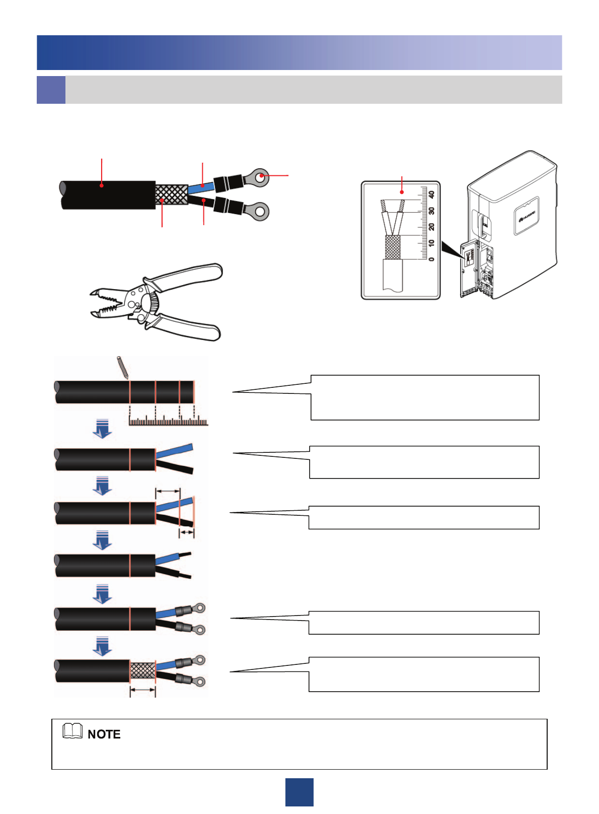
15mm
8mm
14mm
010203040
Appendix
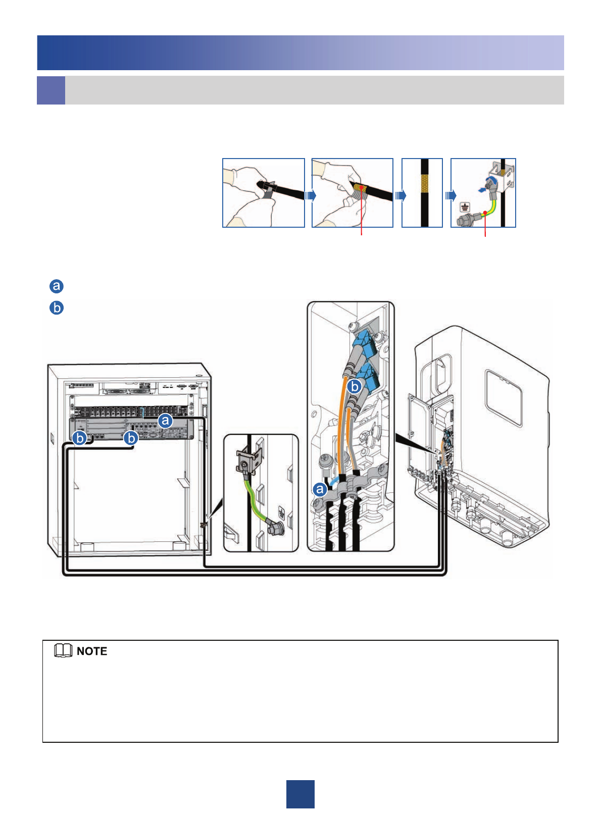
Making OT Terminals by Using a Cable Peeler (Recommended)
b
Add two OT terminals to the end of the power cable connecting to the RRU.
The assembling of OT terminals to the power cable must be complete before the RRU is installed on a
metal pole.
Determine lengths of power cables for different
operations according to the scales on the inner
side of the cover plate of the cabling cavity.
Based on the determined length, remove the
jacket and shielding layer off the power cable.
Add an OT terminal to each wire.
Strip a 15 mm jacket off the power cable to
reveal the shielding layer of the power cable
Remove the jacket from each wire.
Label for preparing
the power cable
-48V DC power cable
Shielding layer
OT terminals
NEG ( - )
RTN ( + )
37
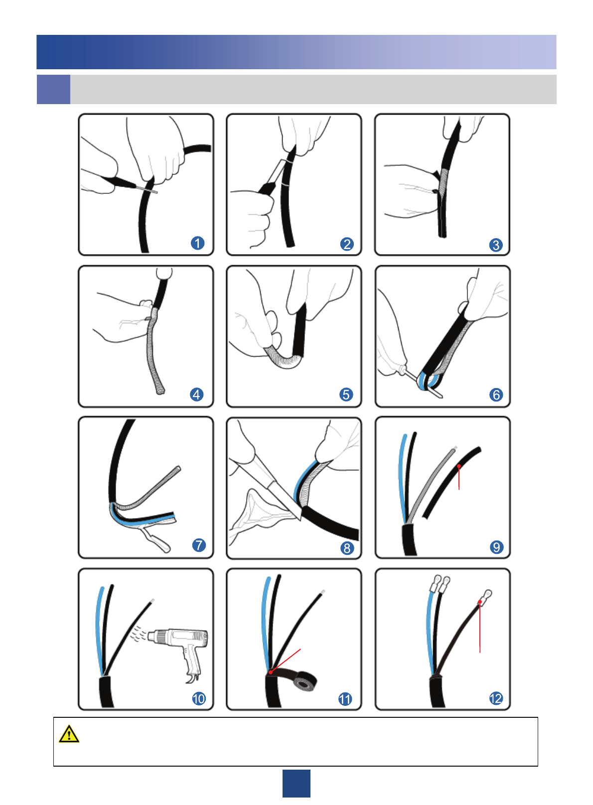
Appendix
c
Do not damage the shielding layer of the power cable when cutting around the jacket.
WARNING
Lead the wires
made of the
shielding layers
through heat-
shrinkable tubes.
Wrap the PVC
insulating tape
at the joint
where the three
wires meet. OT terminal on
the shielding
layer
Adding OT Terminals to the Power Cable on the DCDU side
38
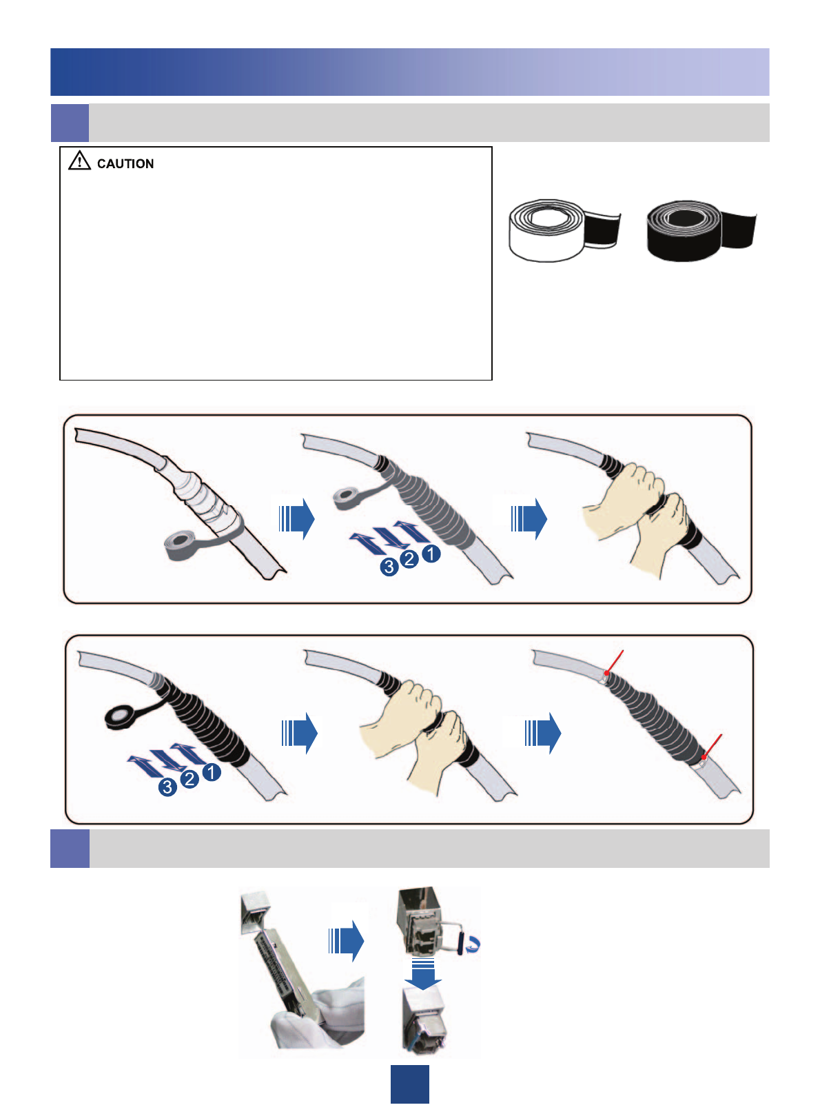
Waterproofing Outdoor Cables
d
zThe waterproof tape should be wrapped for an extra length of 20
mm away from the connectors at both ends.
zThe tapes should be wrapped around the connector from the
lower part to the upper part. When wrapped for another layer, the
tapes may not be cut.
zWhen wrapping the waterproof tape, apply even force to extend
the tape until the width of the tape is 1/2 of the original width.
zWhen wrapping the waterproof tape, ensure that the upper layer
of the tape covers at least 50% of the lower layer.
zThe insulating tape should be wrapped for an extra length of 20
mm away from the connectors at both ends.
zThe last layer of the waterproof tape should be wrapped from the
lower part to the upper part to prevent rainwater from infiltrating into
the tape.
Waterproof tape Insulating tape
Installing the Optical Module
e
Tightly pressing the tape
1. Wrap three layers of waterproof tape.
2. Wrap three layers of insulating tape.
Tightly pressing the tape
Binding cable ties at both
ends of the tape
tie
tie
Appendix
39
Appendix
X9
X8
X7
X6
X5
X4
X3
X2
Cord End
Terminal
GNDOrangeGNDX1.7
SWITCH_INPUT
1+
Twisted pairWhite/orangeSWITCH_INPUT1+X1.6
GNDBlueGNDX1.3
SWITCH_INPUT
0+
Twisted pairWhite/blueSWITCH_INPUT0+X1.2
APM TX+BrownRX485_RX+X1.14
APM TX-Twisted pairWhite/ brownRX485_RX-X1.13
APM RX+GreenRX485_TX+X1.11
APM RX-Twisted pairWhite/ greenRX485_TX-X1.10
LabelWire TypeWire
Color
Signal name of
DB15 connector
DB15
connector
Waterproof
tapes
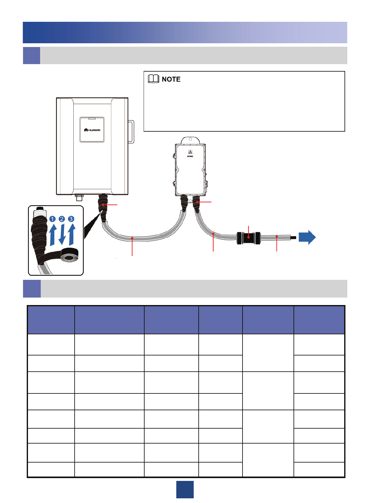
zAfter the corrugated pipe is installed, wrap both ends of the power
cable with waterproof tapes by referring to the following figure.
zWrap the joint spirally upward, downward, and then upward again.
That is, the joint is wrapped by three layers of the tape. Ensure that two
adjacent layers overlap with each other about half the width of the tape.
Power
system
gPin Assignment for the Wires of the RRU Alarm Cable ( DC )
fInstalling the corrugated pipes of AC power cable
Corrugated pipes Corrugated pipes Corrugated pipes
Connector for corrugated pipes
Waterproof
tapes

40
Changes History
This page describes the changes in the RRU3908 V1 Installation Guide.
z02 (2010-07-20)
This is the first commercial release.
Compared with (2010-05-04), the figure of the minimum clearance for RRU are optimized, and
the minimum clearance for the RRU installed on a tower requirements is added.
z01 (2010-05-04)
This is the draft release.

HUAWEI TECHNOLOGIES CO., LTD.
Huawei Industrial Base Bantian Longgang
Shenzhen 518129
People’s Republic of China
www.huawei.com
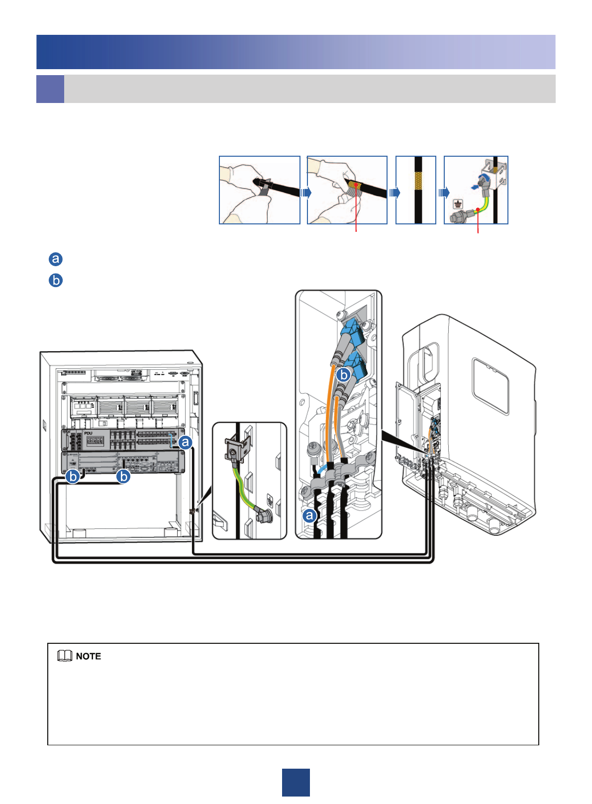
21
Installing the DC RRU
RRU+APM30/APM30H
zThe DC RRU power cable is connected to one of the LOAD4 to LOAD9 terminals of the PDU.
zStrip the jacket of the DC RRU power cable for a small part, press the exposed shielding layer on the strap,
and then connect the PGND cable on the strap to the nearest grounding bolt on the side in the
APM30/APM30H.
zThree power cables can be led through each ground clip.
DC RRU power cable
CPRI optical cable
oRRU Cable Installation Scenarios
Metal Shielding layer (25 mm) PGND cable
Grounding the shielding layer
of the power cable: