Huawei Technologies RRU3931E Remote Radio Unit User Manual Installation Guide
Huawei Technologies Co.,Ltd Remote Radio Unit Installation Guide
Contents
- 1. user manual regulatory compliance statement v2
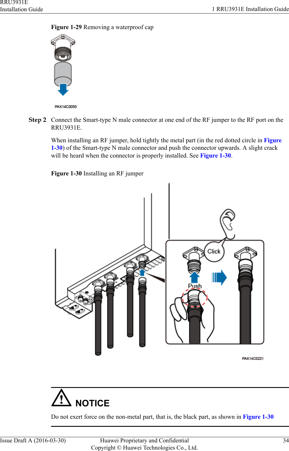
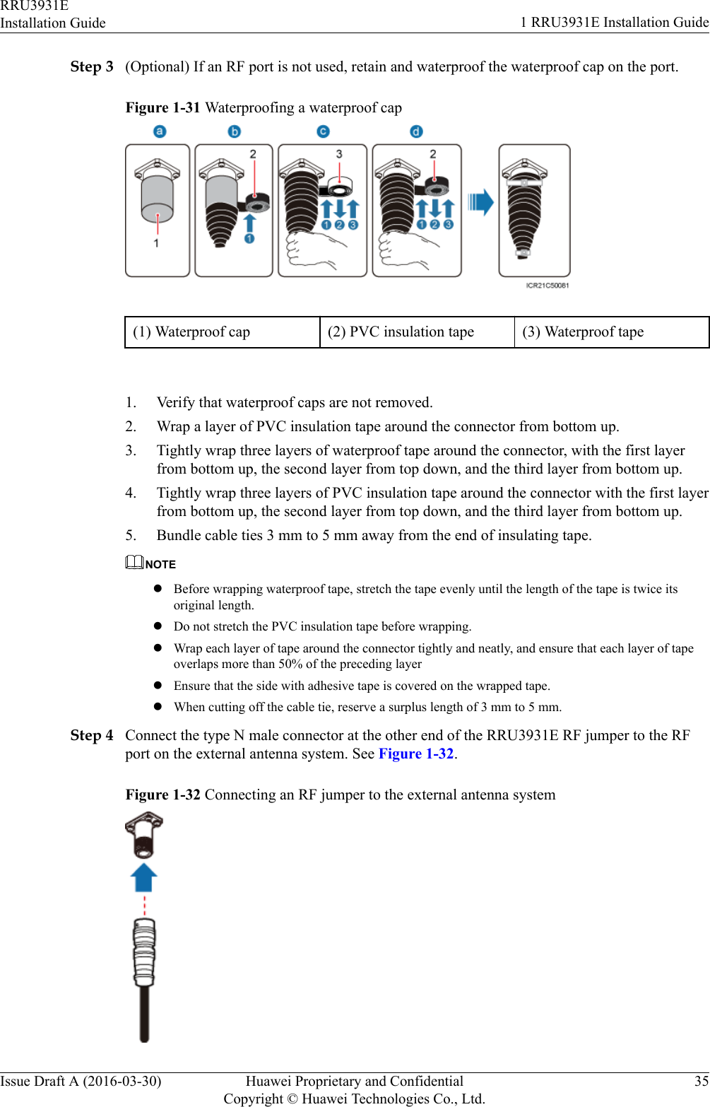
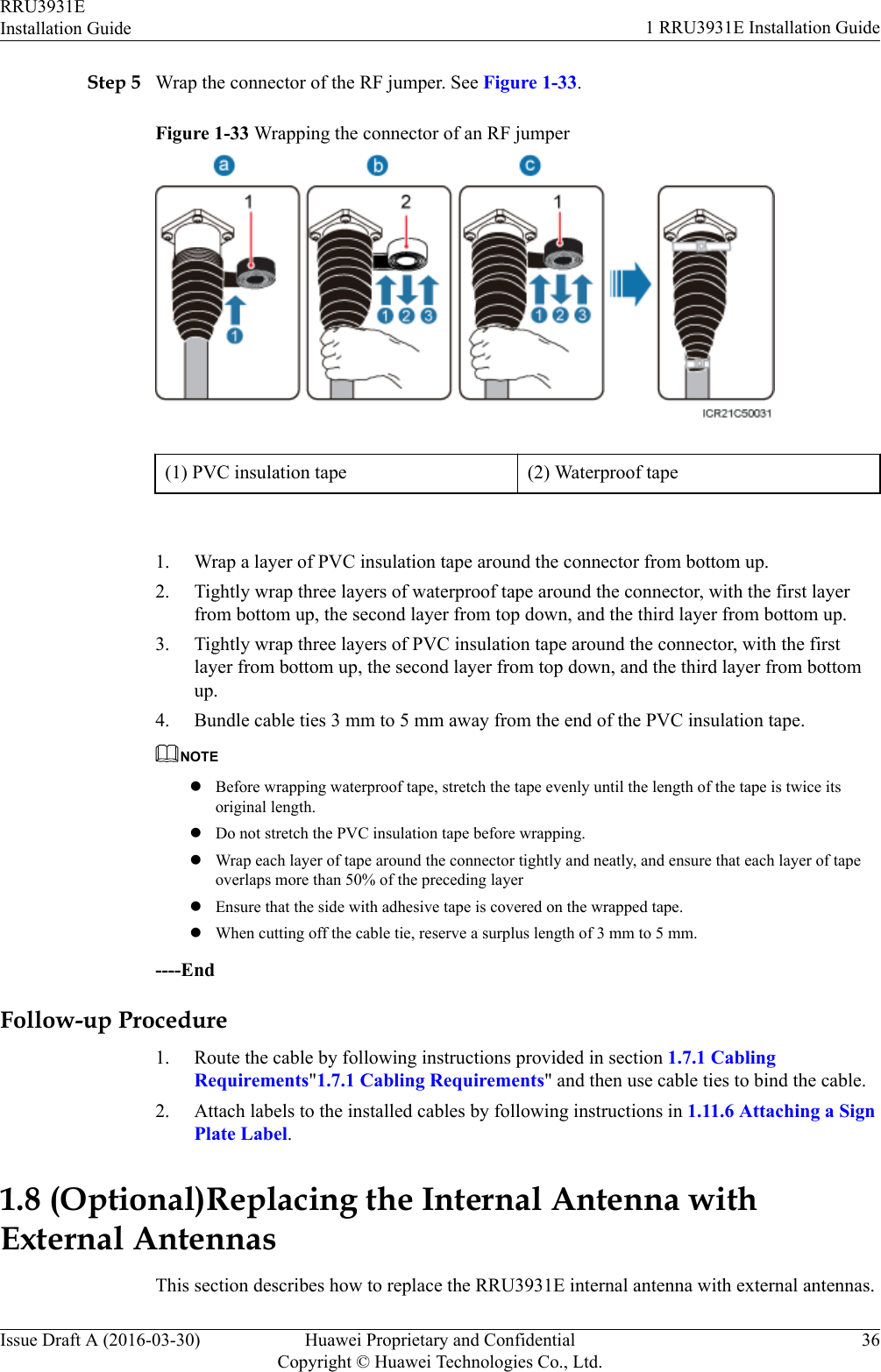
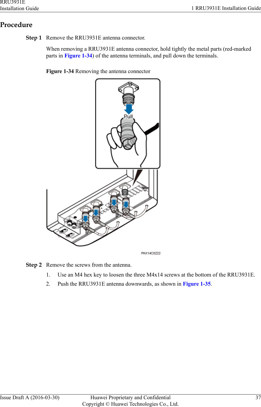
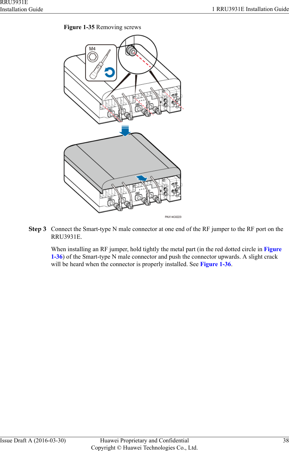
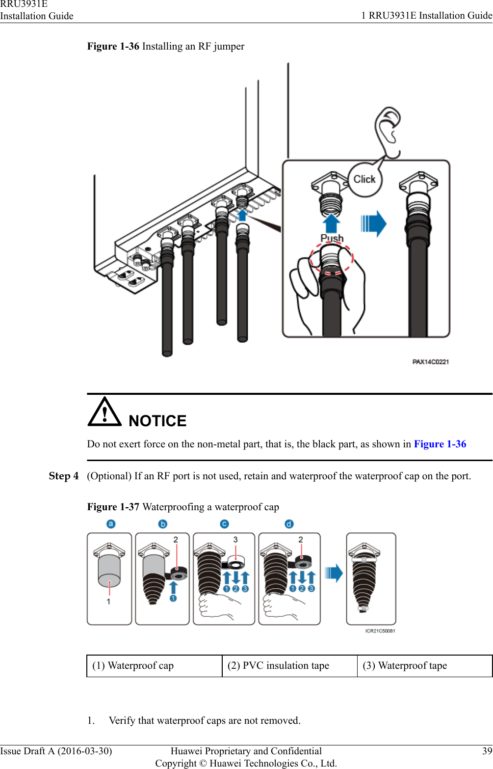
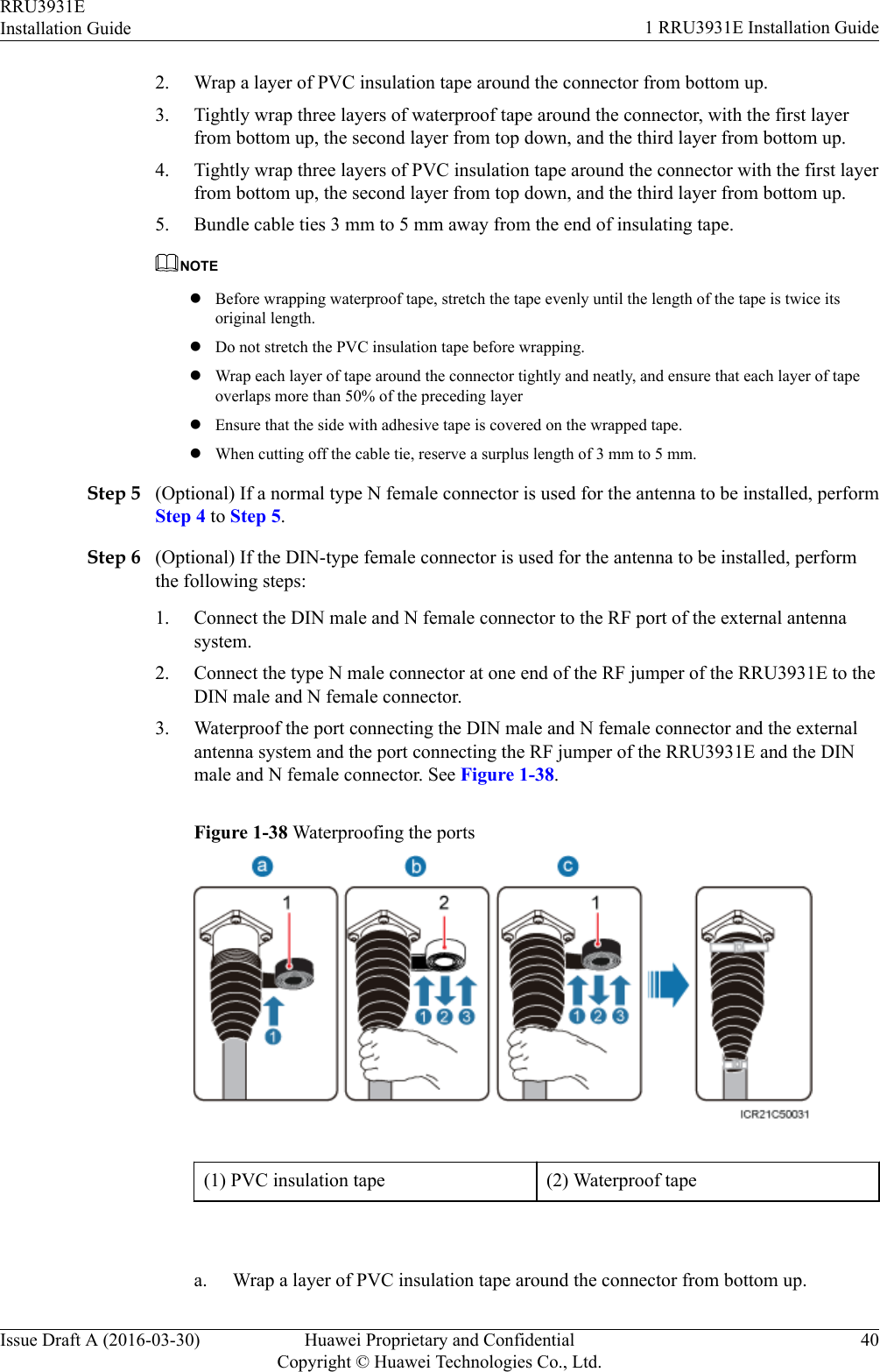
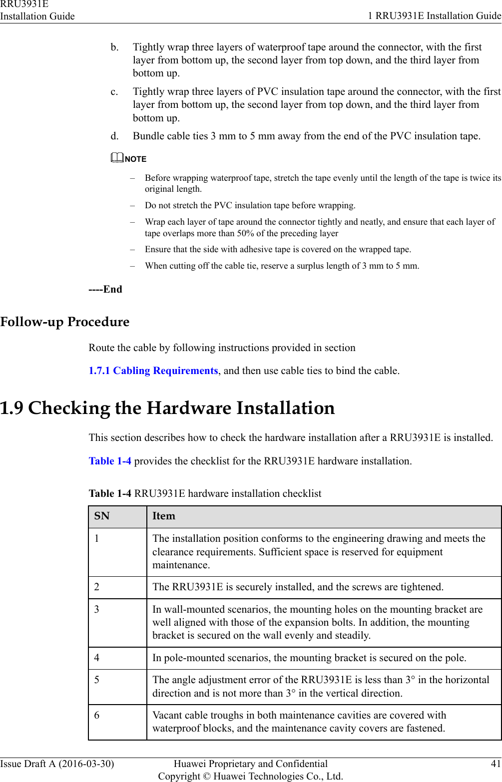
- 2. user manual rru3931e installation guide
- 3. user manual rru3931e site maintenance guid
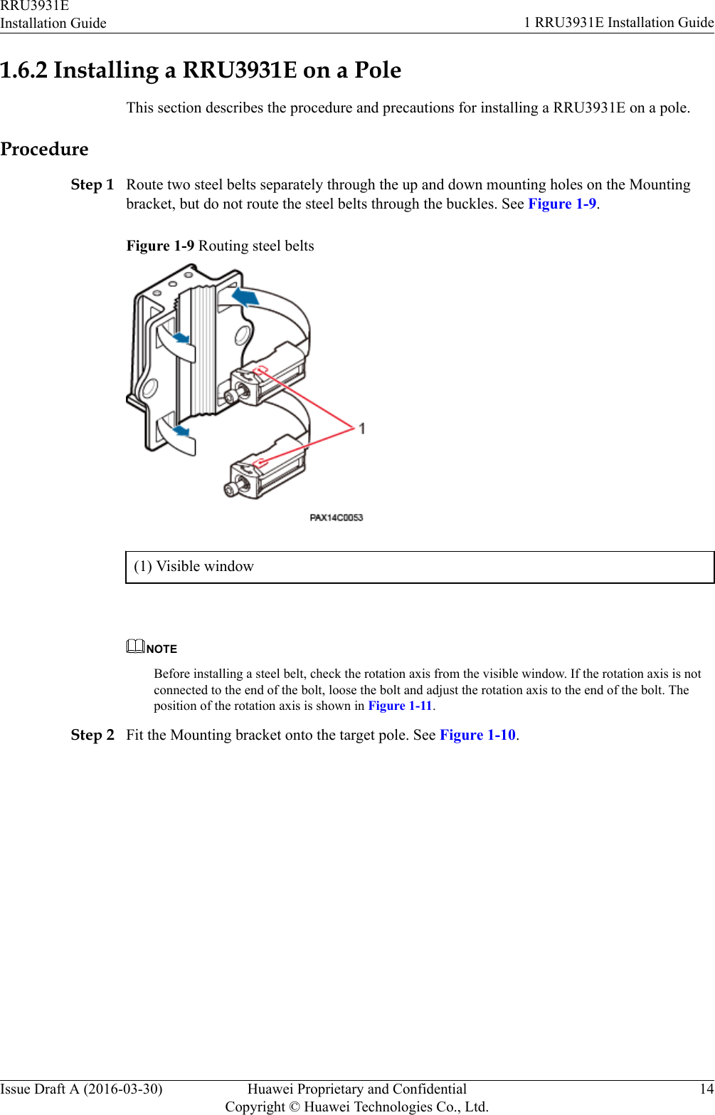
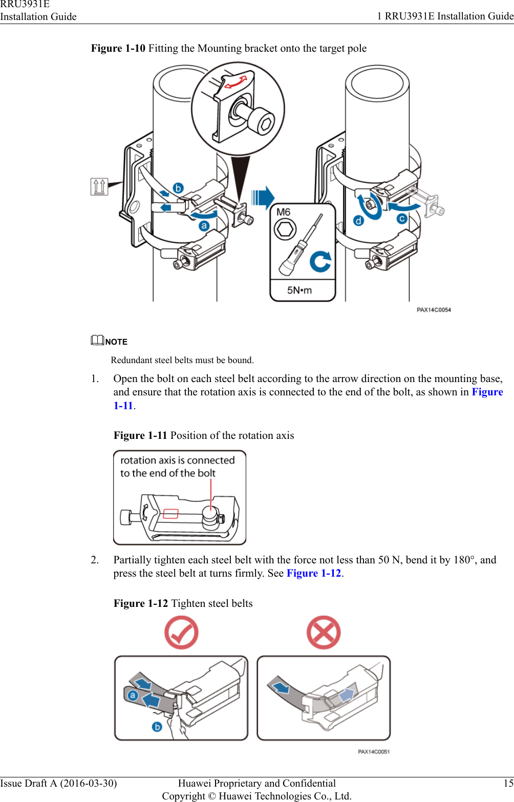
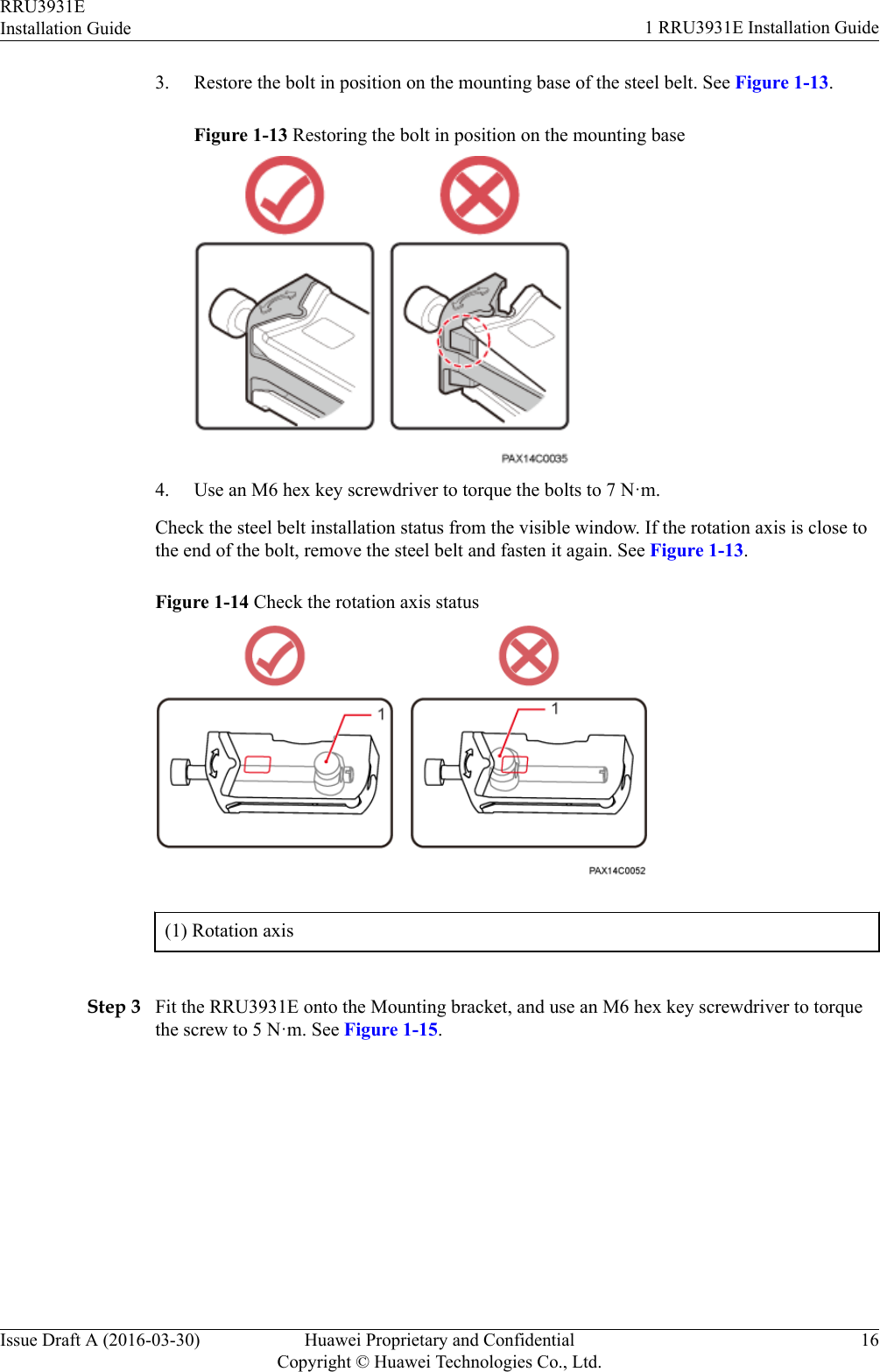
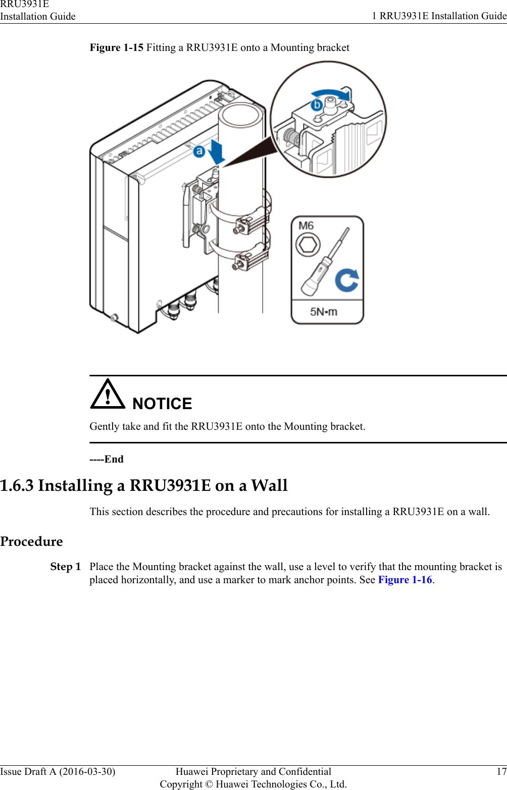
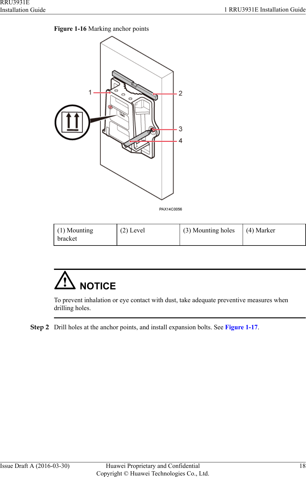
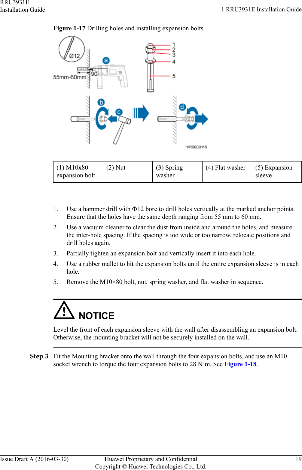
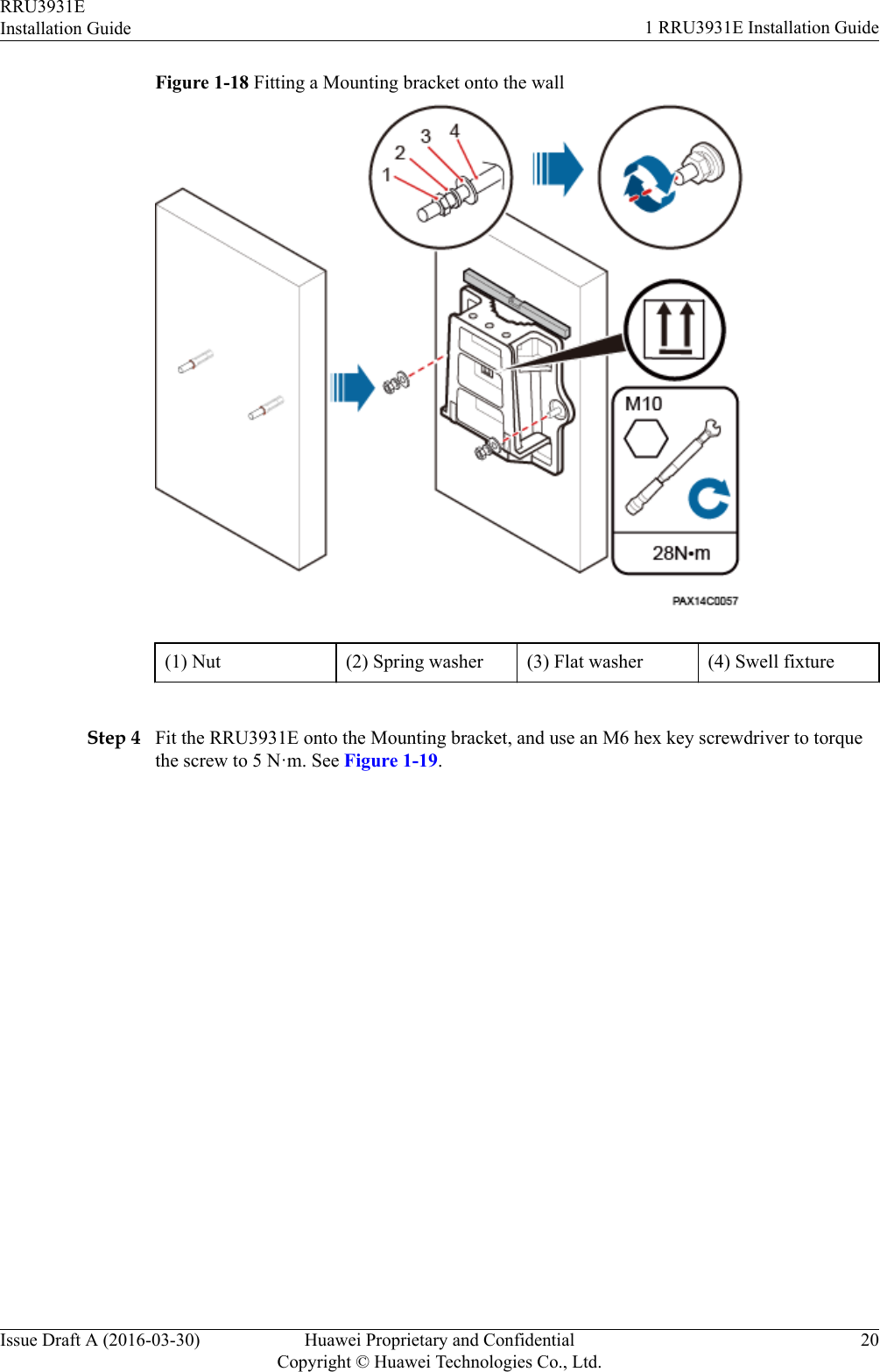
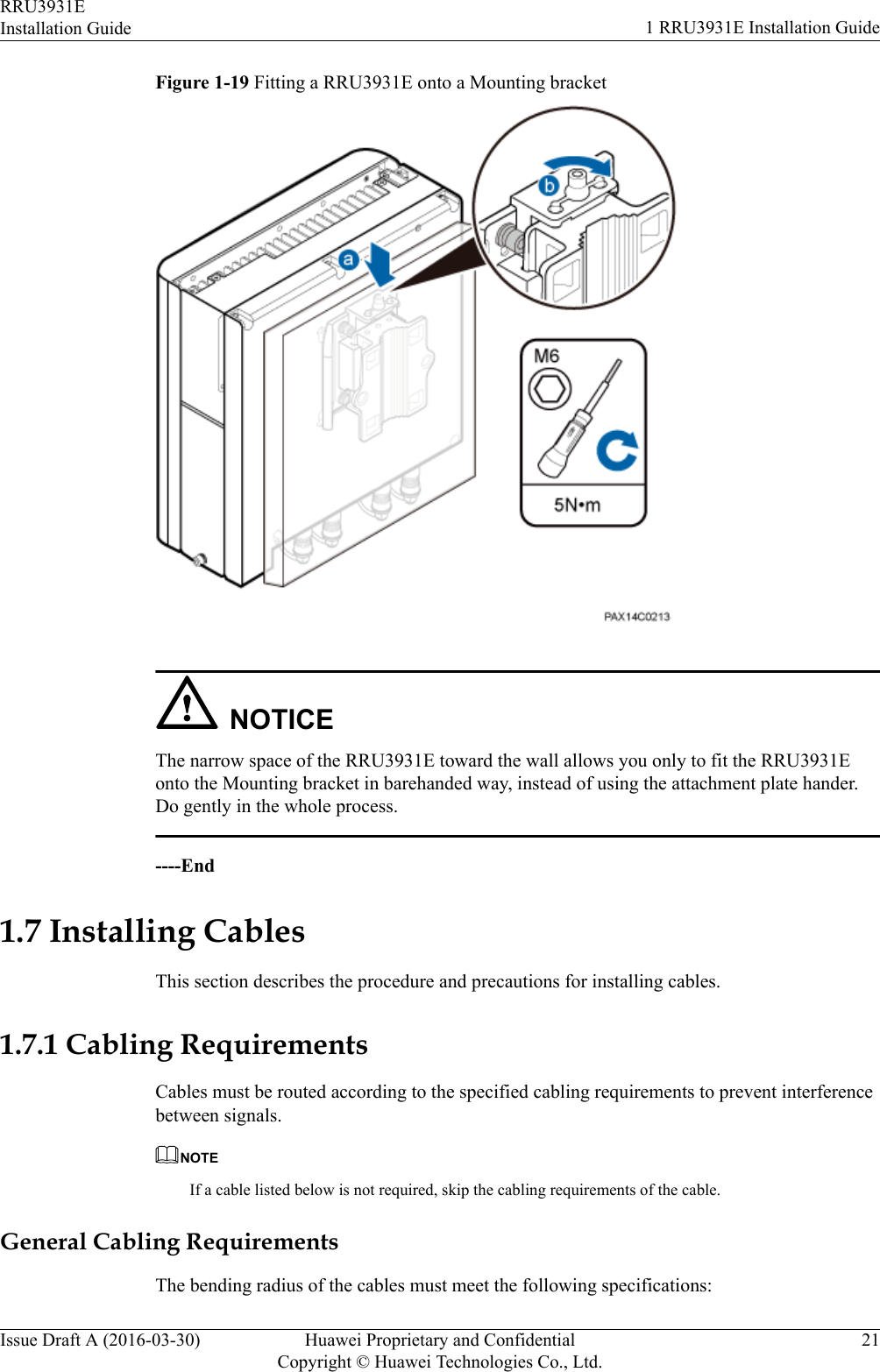
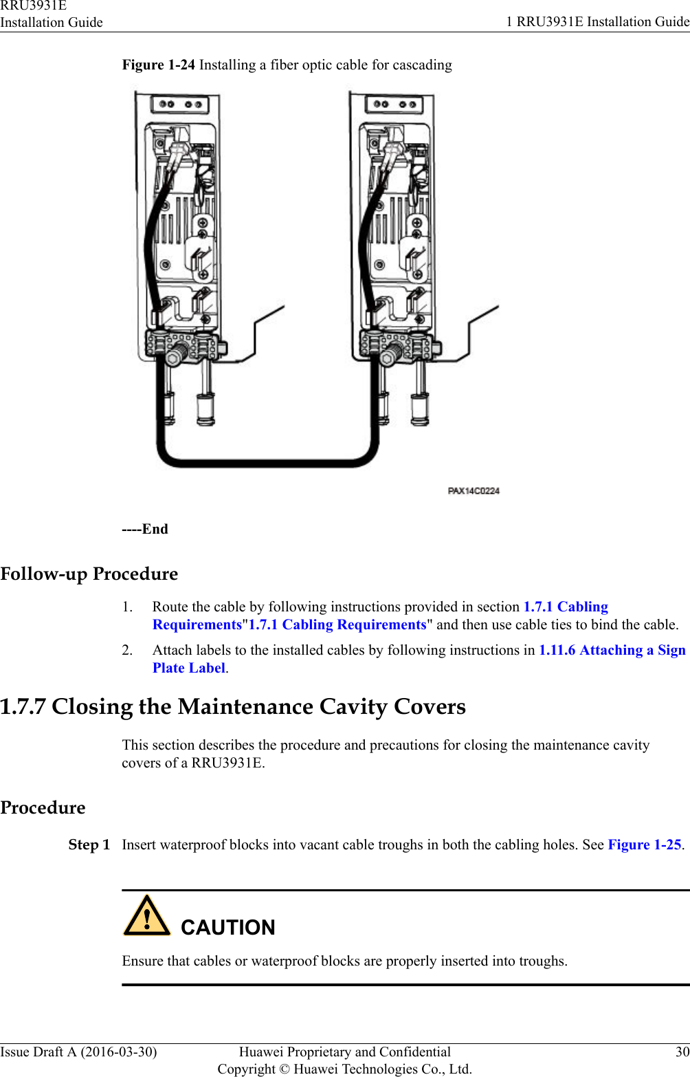
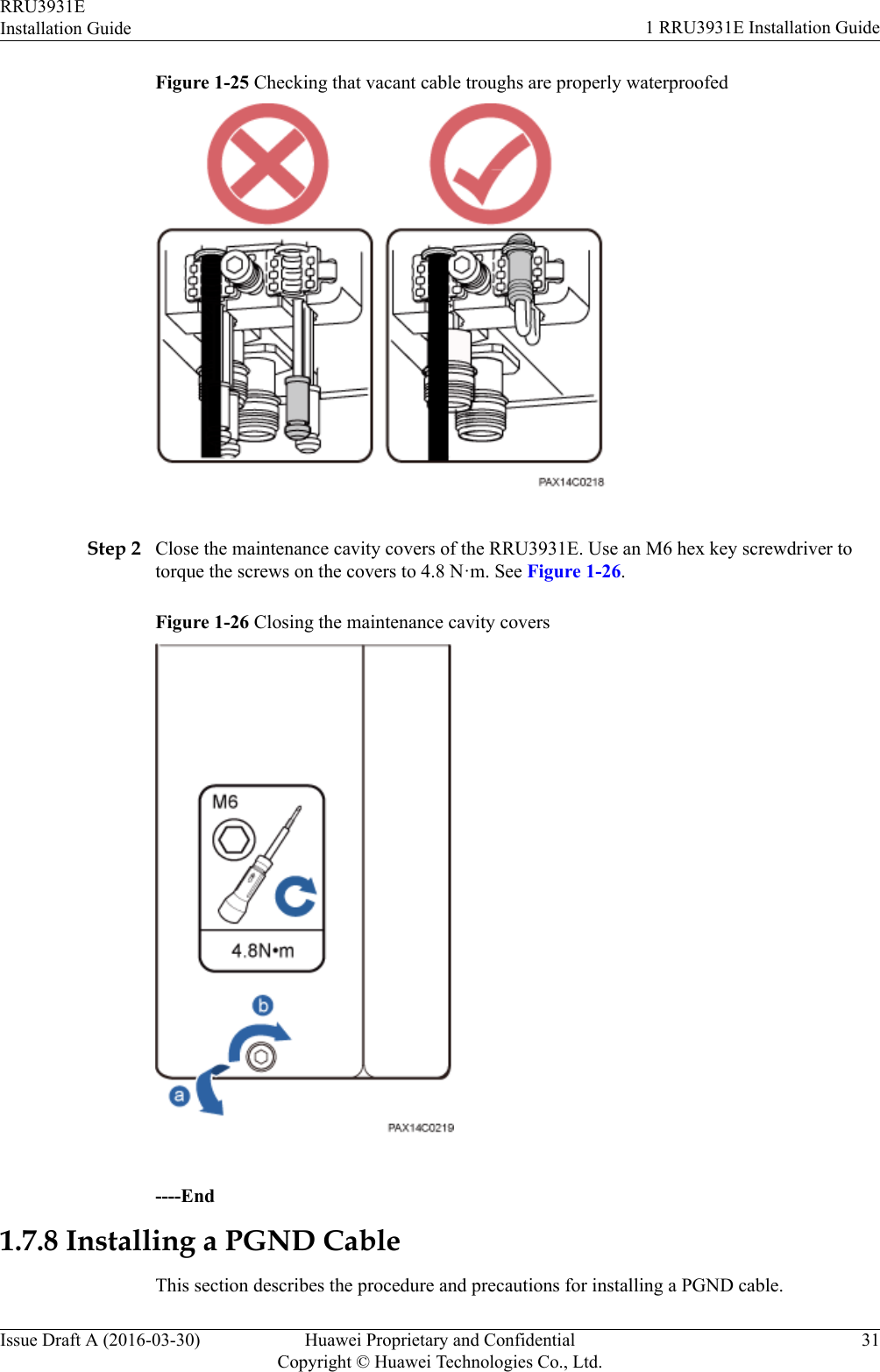
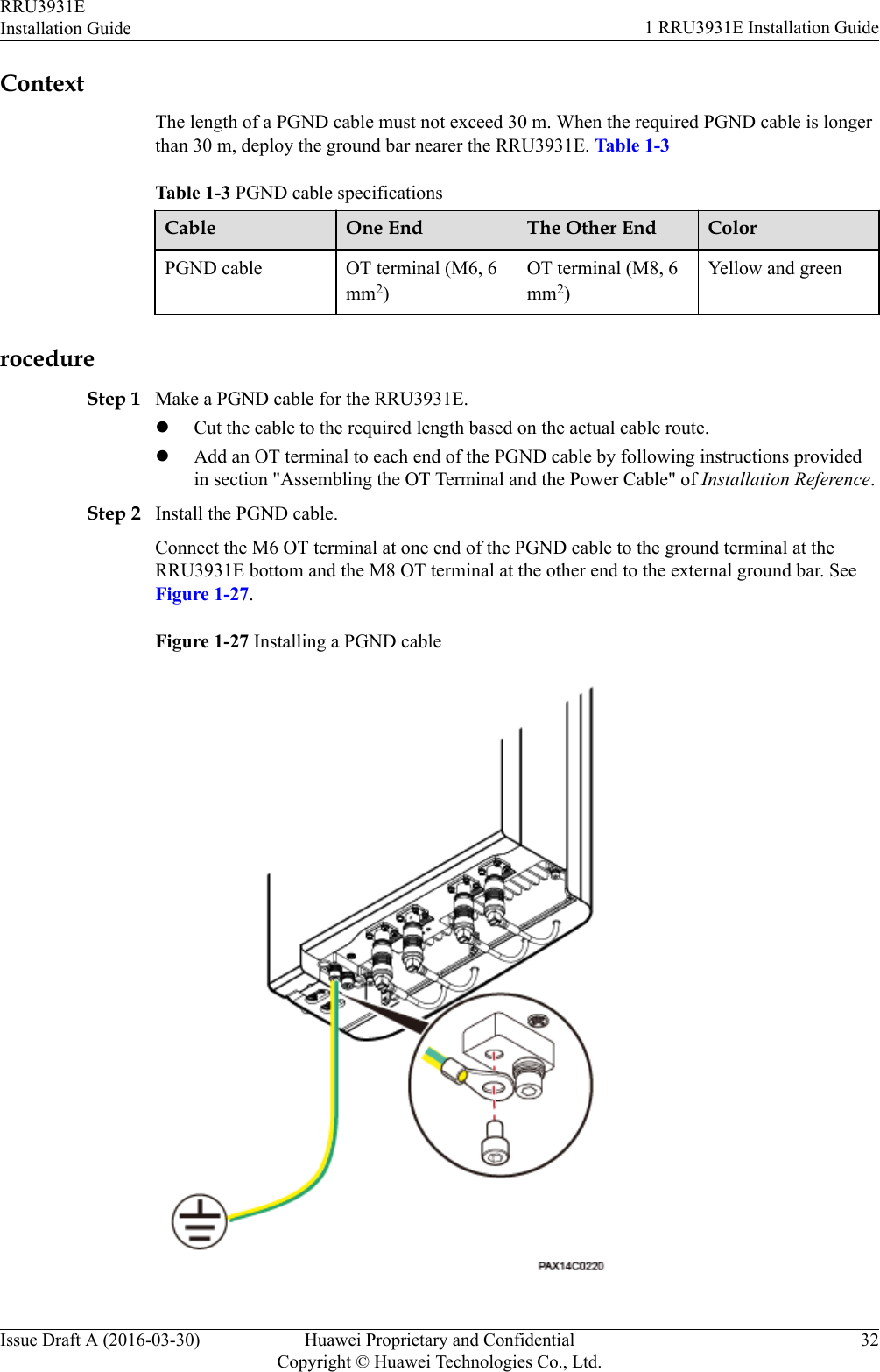
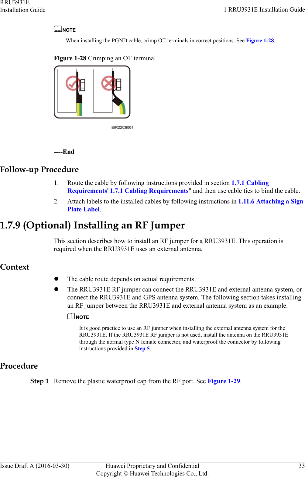
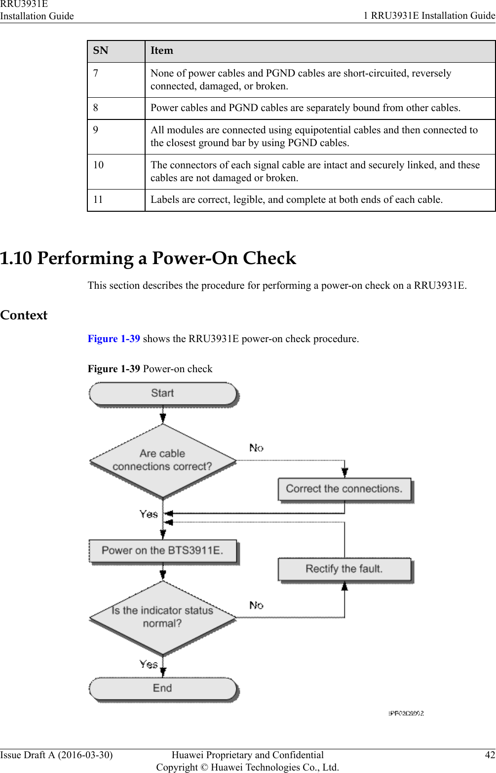
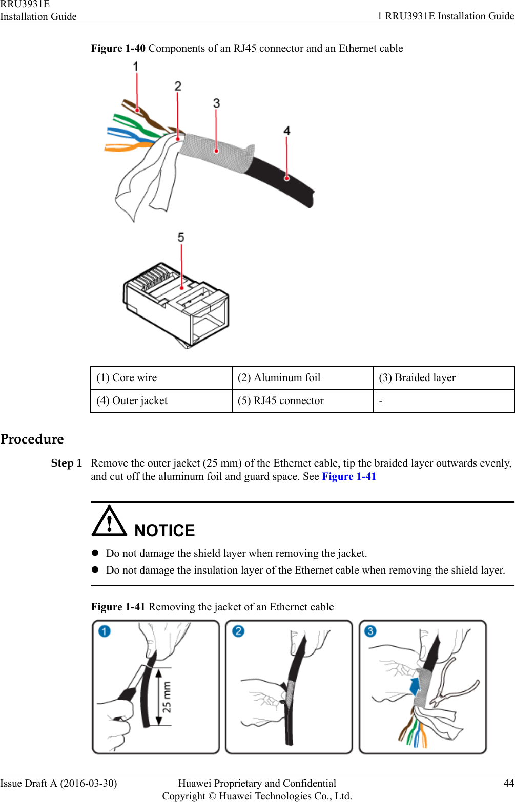
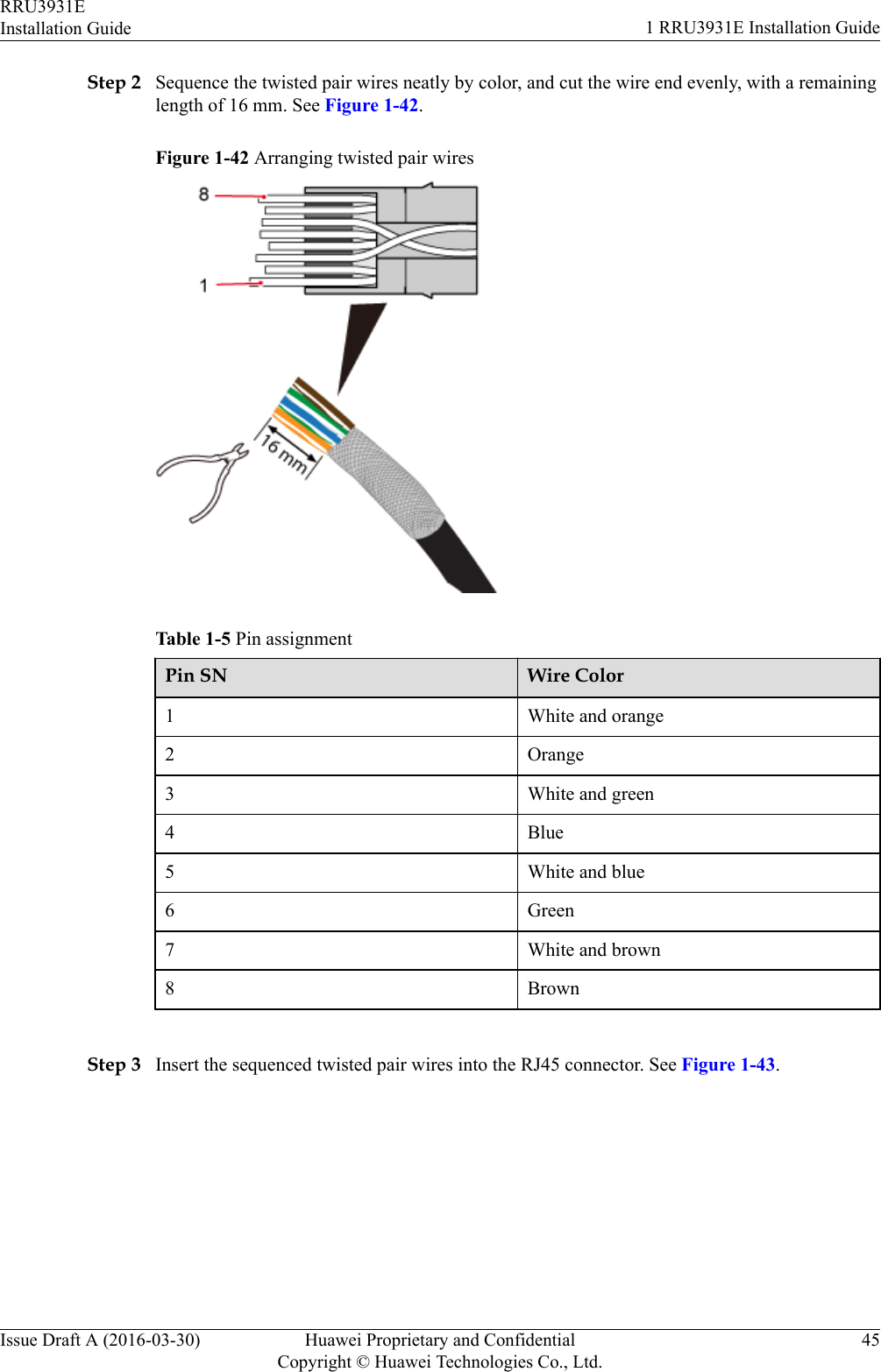
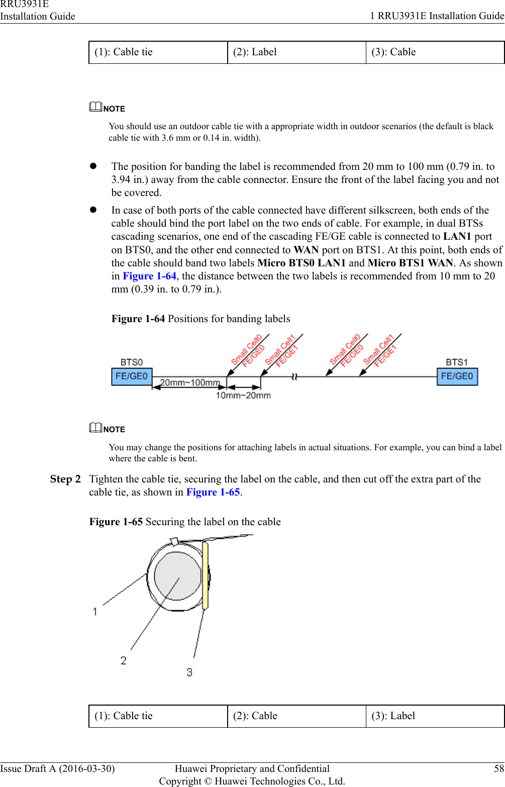
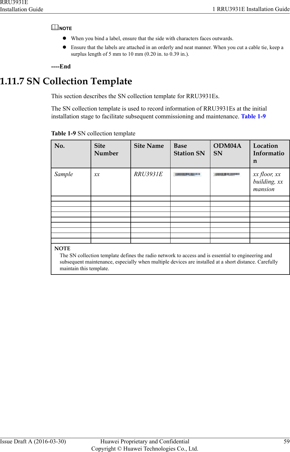
user manual rru3931e installation guide