Huawei Technologies RRU3931E Remote Radio Unit User Manual Installation Guide
Huawei Technologies Co.,Ltd Remote Radio Unit Installation Guide
Contents
- 1. user manual regulatory compliance statement v2
- 2. user manual rru3931e installation guide
- 3. user manual rru3931e site maintenance guid
user manual rru3931e installation guide

RRU3931E
V100R011C10
Installation Guide
Issue Draft A
Date 2016-03-30
HUAWEI TECHNOLOGIES CO., LTD.

Copyright © Huawei Technologies Co., Ltd. 2016. All rights reserved.
No part of this document may be reproduced or transmitted in any form or by any means without prior written
consent of Huawei Technologies Co., Ltd.
Trademarks and Permissions
and other Huawei trademarks are trademarks of Huawei Technologies Co., Ltd.
All other trademarks and trade names mentioned in this document are the property of their respective
holders.
Notice
The purchased products, services and features are stipulated by the contract made between Huawei and the
customer. All or part of the products, services and features described in this document may not be within the
purchase scope or the usage scope. Unless otherwise specified in the contract, all statements, information,
and recommendations in this document are provided "AS IS" without warranties, guarantees or
representations of any kind, either express or implied.
The information in this document is subject to change without notice. Every effort has been made in the
preparation of this document to ensure accuracy of the contents, but all statements, information, and
recommendations in this document do not constitute a warranty of any kind, express or implied.
Huawei Technologies Co., Ltd.
Address: Huawei Industrial Base
Bantian, Longgang
Shenzhen 518129
People's Republic of China
Website: http://www.huawei.com
Email: support@huawei.com
Issue Draft A (2016-03-30) Huawei Proprietary and Confidential
Copyright © Huawei Technologies Co., Ltd.
i

Contents
1 RRU3931E Installation Guide..................................................................................................... 1
1.1 Changes in RRU3931E Installation Guide.....................................................................................................................4
1.2 Installation Preparations................................................................................................................................................. 4
1.2.1 Installation Environment............................................................................................................................................. 4
1.2.2 Reference Documents..................................................................................................................................................5
1.2.3 Tools and Instruments..................................................................................................................................................5
1.2.4 Skills and Requirements for Installation Personnel.....................................................................................................6
1.2.5 Installation Scenarios...................................................................................................................................................7
1.2.6 Installation Clearance Requirements........................................................................................................................... 8
1.3 Unpacking Inspection..................................................................................................................................................... 9
1.4 Obtaining the SN.......................................................................................................................................................... 11
1.5 Installation Process....................................................................................................................................................... 11
1.6 Installing a RRU3931E.................................................................................................................................................12
1.6.1 Mounting Kits............................................................................................................................................................12
1.6.2 Installing a RRU3931E on a Pole..............................................................................................................................14
1.6.3 Installing a RRU3931E on a Wall............................................................................................................................. 17
1.7 Installing Cables........................................................................................................................................................... 21
1.7.1 Cabling Requirements............................................................................................................................................... 21
1.7.2 Cable Connections.....................................................................................................................................................23
1.7.3 Opening the Maintenance Cavity Covers..................................................................................................................24
1.7.4 Installing a Power Cable............................................................................................................................................25
1.7.5 Installing an CPRI Fiber Optic Cable........................................................................................................................27
1.7.6 (Optional) Installing an CPRI Fiber Optic Cable for Cascading...............................................................................29
1.7.7 Closing the Maintenance Cavity Covers................................................................................................................... 30
1.7.8 Installing a PGND Cable........................................................................................................................................... 31
1.7.9 (Optional) Installing an RF Jumper........................................................................................................................... 33
1.8 (Optional)Replacing the Internal Antenna with External Antennas.............................................................................36
1.9 Checking the Hardware Installation............................................................................................................................. 41
1.10 Performing a Power-On Check...................................................................................................................................42
1.11 References...................................................................................................................................................................43
1.11.1 Assembling a Shielded RJ45 Connector and an Ethernet Cable............................................................................. 43
1.11.2 Checking the Appearance of Metal Contact Strips..................................................................................................47
1.11.3 Testing the Connection of Assembled Cables......................................................................................................... 49
RRU3931E
Installation Guide Contents
Issue Draft A (2016-03-30) Huawei Proprietary and Confidential
Copyright © Huawei Technologies Co., Ltd.
ii

1.11.4 Assembling a Tool-less Female Connector (Pressfit Type) and a Power Cable......................................................53
1.11.5 Small Cell Engineering Label..................................................................................................................................56
1.11.6 Attaching a Sign Plate Label................................................................................................................................... 57
1.11.7 SN Collection Template...........................................................................................................................................59
RRU3931E
Installation Guide Contents
Issue Draft A (2016-03-30) Huawei Proprietary and Confidential
Copyright © Huawei Technologies Co., Ltd.
iii
1 RRU3931E Installation Guide
Introduction
This document describes how to install a RRU3931E in different scenarios and provides the
hardware installation checklist as a reference.
Product Version
The following table lists the product versions related to this document.
Product
Name
Solution Version Product Version
RRU3931E lSRAN11.1 and later versions
lRAN18.1 and later versions
leRAN11.1 and later versions
V100R011C10 and later versions
Intended Audience
This document is intended for:
lRRU3931E installation engineers
lSystem engineers
lSite maintenance engineers
Organization
1.1 Changes in RRU3931E Installation Guide1.1 Changes in RRU3931E Installation
Guide
This section describes the changes in RRU3931E Hardware Description.
1.2 Installation Preparations1.2 Installation Preparations
This section describes the preparations for installation. Before starting the installation, you
must get the installation environment ready, obtain the required reference documents, tools,
and instruments, and familiarize yourself with the skills required.
RRU3931E
Installation Guide 1 RRU3931E Installation Guide
Issue Draft A (2016-03-30) Huawei Proprietary and Confidential
Copyright © Huawei Technologies Co., Ltd.
1

1.3 Unpacking Inspection1.3 Unpacking Inspection
This section describes how to unpack and check the delivered materials to ensure that all the
materials are included and intact.
1.4 Obtaining the SN1.4 Obtaining the SN
This section describes how to obtain the serial number (SN) of a RRU3931E. Before
installing the RRU3931E, record its SN for future use during commissioning.
1.5 Installation Process1.5 Installation Process
This section describes the process for installing a RRU3931E. The process includes:
lInstalling a RRU3931E
lInstalling cables
lChecking the hardware installation
lPerforming a power-on check
1.6 Installing a RRU3931E1.6 Installing a RRU3931E
This section describes the procedure and precautions for installing a RRU3931E.
1.7 Installing Cables1.7 Installing Cables
This section describes the procedure and precautions for installing cables.
en-us_topic_0027706033.xmlen-us_topic_0027706033.xml
This section describes the procedure and precautions for adjusting the installation angles of a
RRU3931E.
1.9 Checking the Hardware Installation1.9 Checking the Hardware Installation
This section describes how to check the hardware installation after a RRU3931E is installed.
1.10 Performing a Power-On Check1.10 Performing a Power-On Check
This section describes the procedure for performing a power-on check on a RRU3931E.
1.11 References1.11 References
This section describes reference information and common operations involved during
installation.
1.1 Changes in RRU3931E Installation Guide
This section describes the changes in RRU3931E Hardware Description.
1.2 Installation Preparations
This section describes the preparations for installation. Before starting the installation, you
must get the installation environment ready, obtain the required reference documents, tools,
and instruments, and familiarize yourself with the skills required.
1.3 Unpacking Inspection
This section describes how to unpack and check the delivered materials to ensure that all the
materials are included and intact.
1.4 Obtaining the SN
This section describes how to obtain the serial number (SN) of a RRU3931E. Before
installing the RRU3931E, record its SN for future use during commissioning.
RRU3931E
Installation Guide 1 RRU3931E Installation Guide
Issue Draft A (2016-03-30) Huawei Proprietary and Confidential
Copyright © Huawei Technologies Co., Ltd.
2

1.5 Installation Process
This section describes the process for installing a RRU3931E.
1.6 Installing a RRU3931E
This section describes the procedure and precautions for installing a RRU3931E.
1.7 Installing Cables
This section describes the procedure and precautions for installing cables.
1.8 (Optional)Replacing the Internal Antenna with External Antennas
This section describes how to replace the RRU3931E internal antenna with external antennas.
1.9 Checking the Hardware Installation
This section describes how to check the hardware installation after a RRU3931E is installed.
1.10 Performing a Power-On Check
This section describes the procedure for performing a power-on check on a RRU3931E.
1.11 References
This section describes reference information and common operations involved during
installation.
RRU3931E
Installation Guide 1 RRU3931E Installation Guide
Issue Draft A (2016-03-30) Huawei Proprietary and Confidential
Copyright © Huawei Technologies Co., Ltd.
3

1.1 Changes in RRU3931E Installation Guide
This section describes the changes in RRU3931E Hardware Description.
Draft A (2016-03-30)
This is a draft.
1.2 Installation Preparations
This section describes the preparations for installation. Before starting the installation, you
must get the installation environment ready, obtain the required reference documents, tools,
and instruments, and familiarize yourself with the skills required.
1.2.1 Installation Environment
Before starting the installation, ensure that the power supply equipment, transmission
equipment, and related matching equipment are ready.
Precautions for Site Selection
lDo not install a RRU3931E near an interference source, such as a broadcast and
television tower, high and low-voltage substation, high-voltage tower, high-power radio
transmitter, and radar station.
lFor the sake of surge protection, the mounting height of a RRU3931E should not be
greater than 10 m. Do not install a RRU3931E along a highway or railway or on the
mountain top, tower, standalone pole in a suburban area or open field, or standalone
rooftop in a non-urban area.
Requirements for the Upper-level Circuit Breaker
Slow-blow fuses of the gL (DIN VDE)/gG (IEC) class in accordance with IEC60269-1 are
recommended. Fuses of the same specifications must be configured for L and N wires for the
sake of O&M security.
Type C bipolar circuit breakers in accordance with IEC60934 are recommended. Circuit
breakers must be configured for L and N wires for the sake of O&M security.
Table 1-1 describes the recommended specifications.
Table 1-1 Requirements on the upper-level circuit breakers and power cables
Power Supply Current of the Upper-
level AC Circuit
Breakers (or Fuses)
Cross-Sectional Area of
the Input Power Cable
220 V AC single-phase lMinimum value: 5 A
lRecommended value: 16
A
1.5 mm2 to 2.5 mm2
110 V AC dual-live-wire
RRU3931E
Installation Guide 1 RRU3931E Installation Guide
Issue Draft A (2016-03-30) Huawei Proprietary and Confidential
Copyright © Huawei Technologies Co., Ltd.
4
Power Supply Current of the Upper-
level AC Circuit
Breakers (or Fuses)
Cross-Sectional Area of
the Input Power Cable
110 V AC single-phase lMaximum value: 20 A
NOTE
lThe requirements provided in the preceding table are based on the peak power of a RRU3931E and
do not represent power consumption when the RRU3931E is running.
lMinimum value: Ensures that a RRU3931E can work normally under normal circumstances.
However, lightning strikes or abnormal voltage fluctuations may trip the circuit breaker or melt the
fuse.
lRecommended value: Ensures that a RRU3931E can work normally under normal circumstances
and that the circuit breaker does not trip in the event of lightning strikes or abnormal voltage
fluctuations.
lMaximum value: Indicates the maximum rated current allowed in the product design.
Requirements for Surge Protection and Grounding
Huawei by default uses a three-core power cable to connect a RRU3931E and external power
supply equipment. The power supply side must ensure that the PE wire of the three-core
power cable can be properly grounded. In outdoor installation scenarios or outdoor cabling
scenarios, PGND cables must be used to guarantee the surge protection and grounding for the
ground terminals of the mounting kits.
Requirements for power supply
During installation, power off the RRU3931E.
1.2.2 Reference Documents
This section describes reference documents required for installation.
Before starting the installation, you must be familiar with the following reference documents:
lSafety Information
lRRU3931E Hardware Description
1.2.3 Tools and Instruments
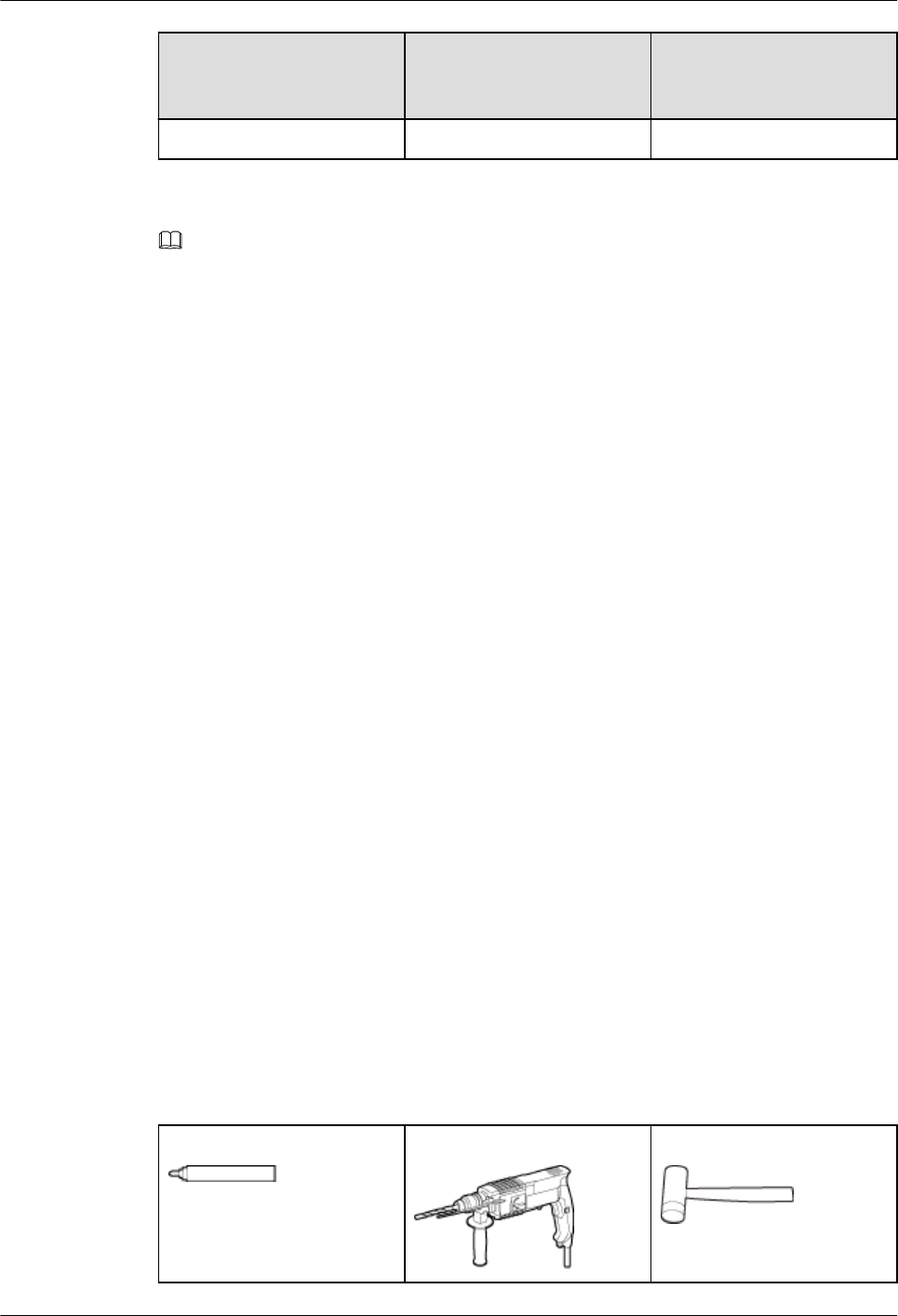
Before starting the installation, prepare the following tools and instruments.
Marker (diameter ≤ 10 mm) Hammer drill (Ø12 bore) Rubber mallet
RRU3931E
Installation Guide 1 RRU3931E Installation Guide
Issue Draft A (2016-03-30) Huawei Proprietary and Confidential
Copyright © Huawei Technologies Co., Ltd.
5
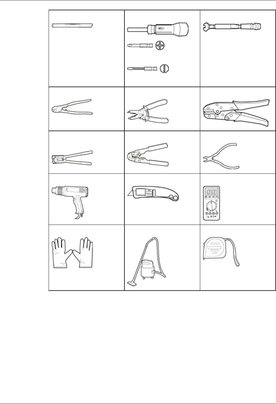
Level Torque screwdriver
Phillips (M3, M4)
Flat-head (M6, M8)
Torque wrench
Cable cutter Wire stripper COAX crimping tool
Crimping tool for power
cables
RJ45 crimping tool Diagonal pliers
Heat gun Utility knife Multimeter
ESD gloves Vacuum cleaner Measuring tape
1.2.4 Skills and Requirements for Installation Personnel
Installation personnel must be qualified, trained, and familiar with correct operation methods
and safety precautions before performing any operations.
Before starting the installation, pay attention to the following items:
lThe customer's technical engineers must be trained by Huawei and be familiar with the
proper installation and engineering methods.
lThe number of required installation personnel depends on the engineering schedule and
installation environment. Generally, three to five installation personnel are necessary.
RRU3931E
Installation Guide 1 RRU3931E Installation Guide
Issue Draft A (2016-03-30) Huawei Proprietary and Confidential
Copyright © Huawei Technologies Co., Ltd.
6
1.2.5 Installation Scenarios
The RRU3931E can be installed on a pole or a wall.
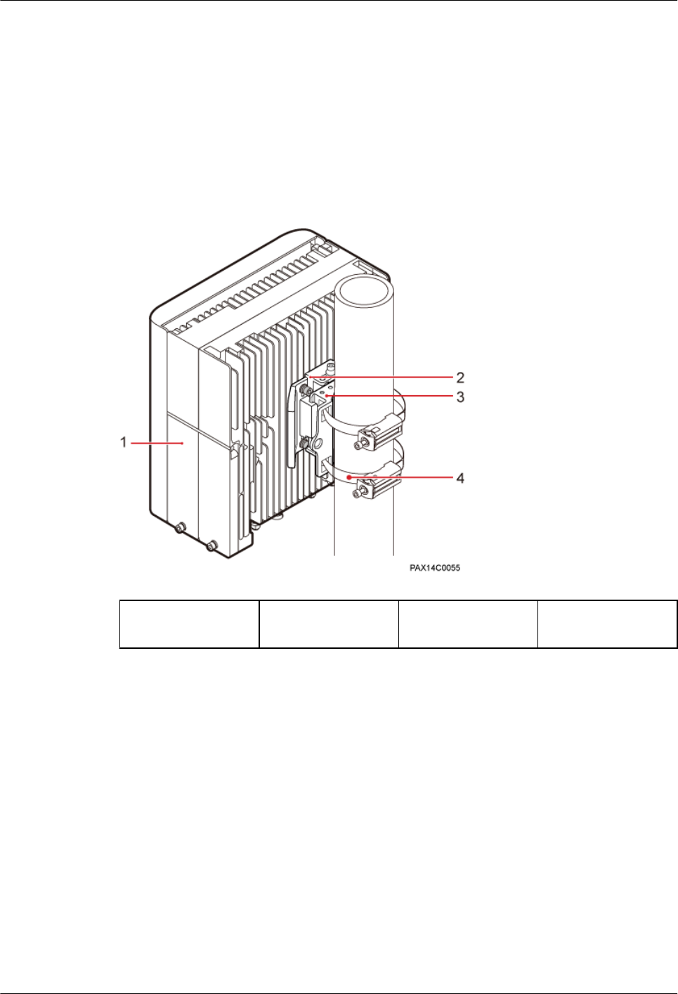
Pole-mounted Installation
A RRU3931E can be installed on a pole with a diameter of 60 mm to 381 mm.
Figure 1-1 illustrates a pole-mounted RRU3931E.
Figure 1-1 Pole-mounted installation
(1) RRU3931E (2) Attachment plate (3) Mounting
bracket
(4) Steel belt
Wall-mounted Installation
In wall-mounted installation scenarios, note the following:
lThe wall has a capacity of bearing at least four times the weight of the RRU3931E to be
installed without damage.
lExpansion bolts must be torqued to 28 N·m to ensure the bolts work properly without
causing cracks on the wall.
Figure 1-2 illustrates a wall-mounted RRU3931E.
RRU3931E
Installation Guide 1 RRU3931E Installation Guide
Issue Draft A (2016-03-30) Huawei Proprietary and Confidential
Copyright © Huawei Technologies Co., Ltd.
7
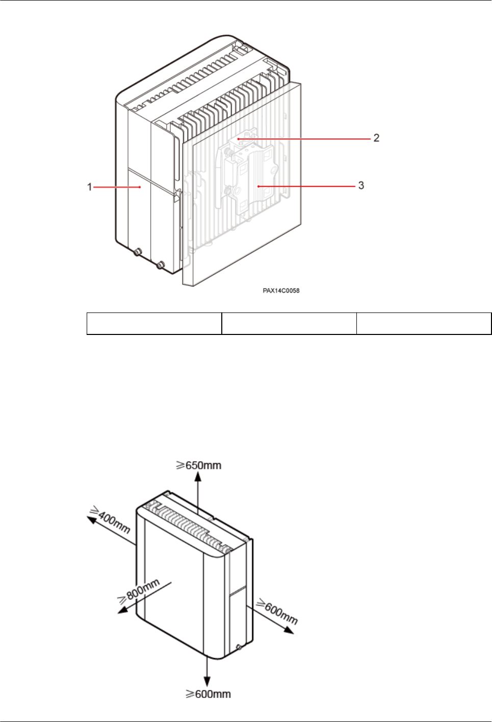
Figure 1-2 Wall-mounted installation
(1) RRU3931E (2) Attachment plate (3) Mounting bracket
1.2.6 Installation Clearance Requirements
This section describes the clearance requirements for installing a RRU3931E on a pole or
wall.
Figure 1-3 shows the recommended installation clearances around a RRU3931E.
Figure 1-3 Recommended installation clearances around a RRU3931E
RRU3931E
Installation Guide 1 RRU3931E Installation Guide
Issue Draft A (2016-03-30) Huawei Proprietary and Confidential
Copyright © Huawei Technologies Co., Ltd.
8
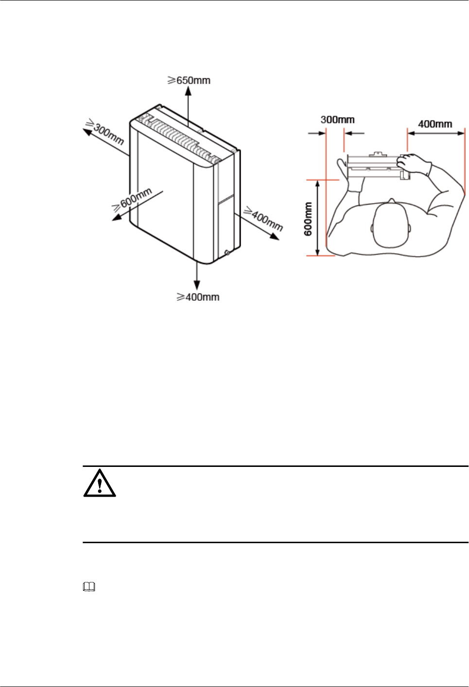
Figure 1-4 shows the minimum installation clearances around a RRU3931E.
Figure 1-4 Minimum installation clearances around a RRU3931E
1.3 Unpacking Inspection
This section describes how to unpack and check the delivered materials to ensure that all the
materials are included and intact.
Prerequisites
NOTICE
After a RRU3931E is unpacked, power it on within 24 hours. If the RRU3931E is powered
off for maintenance, restore power to it within 24 hours.
Context
NOTE
When transporting, moving, or installing the equipment, components, or parts, you must:
lPrevent them from colliding with doors, walls, shelves, or other objects.
lWear clean gloves, and avoid touching the equipment, components, or parts with bare hands, sweat-
soaked gloves, or dirty gloves.
RRU3931E
Installation Guide 1 RRU3931E Installation Guide
Issue Draft A (2016-03-30) Huawei Proprietary and Confidential
Copyright © Huawei Technologies Co., Ltd.
9
Procedure
Step 1 Check the total number of articles in each packing case against the packing list.
If... Then...
The total number tallies with the packing
list
Go to Step 2
The total number does not tally with the
packing list
Find out the cause and contact the local
Huawei office.
Step 2 Check the exterior of each packing case.
If... Then...
The outer packing is intact Go to Step 3.
The packing case is severely damaged or
soaked
Find out the cause and contact the local
Huawei office.
Step 3 Check the type and quantity of the equipment in each packing case against the packing list.
If... Then...
The type and quantity tallies with the
packing list
Sign the Packing List with the customer.
There is any shipment shortage or wrong
shipment
Fill in and submit the Cargo Shortage and
Mishandling Report.
There is damaged shipment Fill in and submit the Article Replacement
Report.
NOTICE
To protect the equipment from damage, keep the unpacked equipment and packing materials
indoors. To help find out the cause of any damage in the future, take photos of the storeroom,
rusted or eroded equipment, packing cases, and packing materials, and then file the photos.
----End
RRU3931E
Installation Guide 1 RRU3931E Installation Guide
Issue Draft A (2016-03-30) Huawei Proprietary and Confidential
Copyright © Huawei Technologies Co., Ltd.
10
1.4 Obtaining the SN
This section describes how to obtain the serial number (SN) of a RRU3931E. Before
installing the RRU3931E, record its SN for future use during commissioning.
Context
The SN uniquely identifies a device and is required during commissioning. The SN label of a
RRU3931E is attached to the surface of the RRU3931E.
Procedure
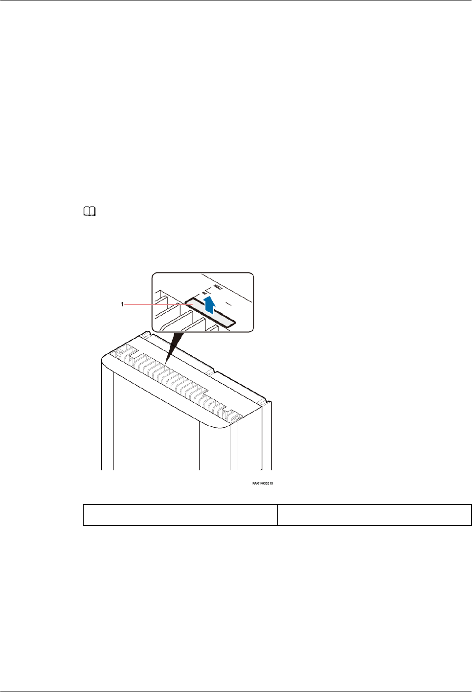
Step 1 Remove the backup SN label from the surface of the RRU3931E. See Figure 1-5
NOTE
Before removing the backup SN label, photograph it.
Figure 1-5 Removing the SN label
(1) Backup SN label -
Step 2 Record the SN by using the template described in section 1.11.7 SN Collection Template,
and report it to the RRU3931E commissioning personnel.
----End
1.5 Installation Process
This section describes the process for installing a RRU3931E.
The process includes:
RRU3931E
Installation Guide 1 RRU3931E Installation Guide
Issue Draft A (2016-03-30) Huawei Proprietary and Confidential
Copyright © Huawei Technologies Co., Ltd.
11
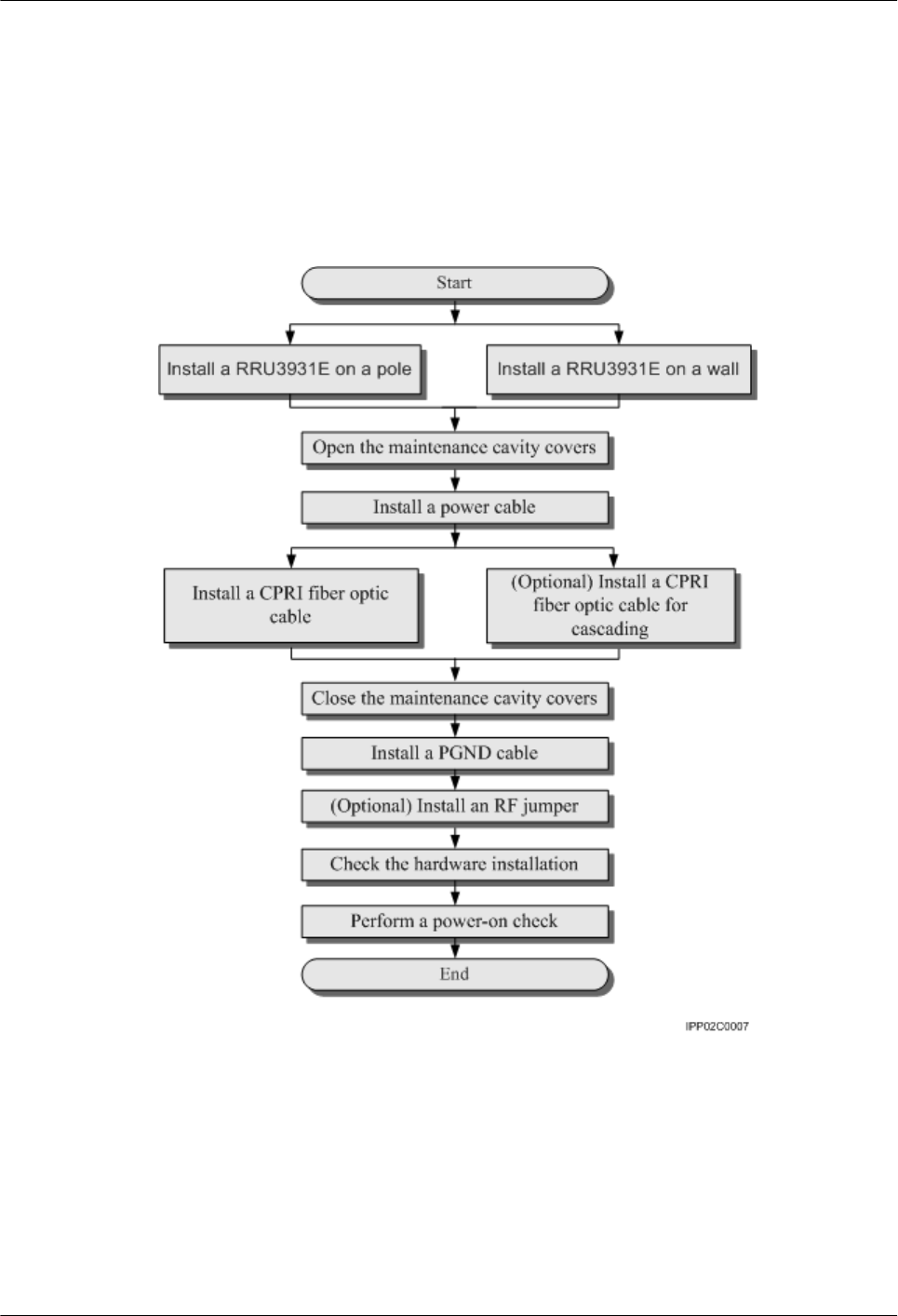
lInstalling a RRU3931E
lInstalling cables
lChecking the hardware installation
lPerforming a power-on check
Figure 1-6 outlines the process for installing a RRU3931E.
Figure 1-6 Process for installing a RRU3931E
1.6 Installing a RRU3931E
This section describes the procedure and precautions for installing a RRU3931E.
1.6.1 Mounting Kits
This section describes the kits for mounting a RRU3931E on a pole or wall.
RRU3931E
Installation Guide 1 RRU3931E Installation Guide
Issue Draft A (2016-03-30) Huawei Proprietary and Confidential
Copyright © Huawei Technologies Co., Ltd.
12
Slim Attachment Plate
Figure 1-7 shows the appearance of a slim attachment plate.
Figure 1-7 Slim attachment plate
(1) RRU3931E (2) Slim attachment plate
Mounting Bracket
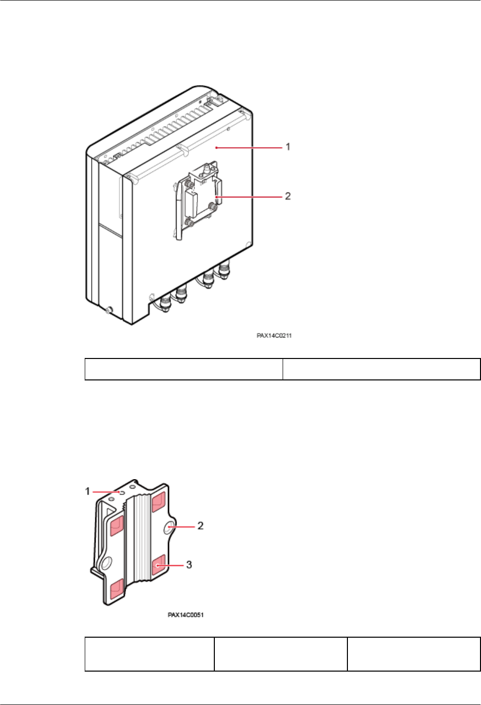
Figure 1-8 shows the appearance of a Mounting bracket.
Figure 1-8 Mounting bracket
(1) Hole for a fastening
screw
(2) Mounting hole for an
expansion bolt
(3) Mounting hole for a steel
belt
RRU3931E
Installation Guide 1 RRU3931E Installation Guide
Issue Draft A (2016-03-30) Huawei Proprietary and Confidential
Copyright © Huawei Technologies Co., Ltd.
13
1.6.2 Installing a RRU3931E on a Pole
This section describes the procedure and precautions for installing a RRU3931E on a pole.
Procedure
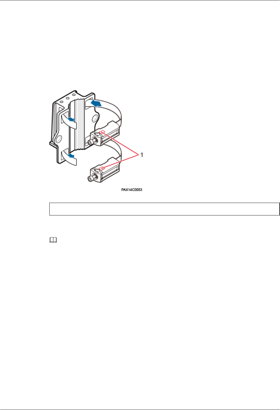
Step 1 Route two steel belts separately through the up and down mounting holes on the Mounting
bracket, but do not route the steel belts through the buckles. See Figure 1-9.
Figure 1-9 Routing steel belts
(1) Visible window
NOTE
Before installing a steel belt, check the rotation axis from the visible window. If the rotation axis is not
connected to the end of the bolt, loose the bolt and adjust the rotation axis to the end of the bolt. The
position of the rotation axis is shown in Figure 1-11.
Step 2 Fit the Mounting bracket onto the target pole. See Figure 1-10.
RRU3931E
Installation Guide 1 RRU3931E Installation Guide
Issue Draft A (2016-03-30) Huawei Proprietary and Confidential
Copyright © Huawei Technologies Co., Ltd.
14
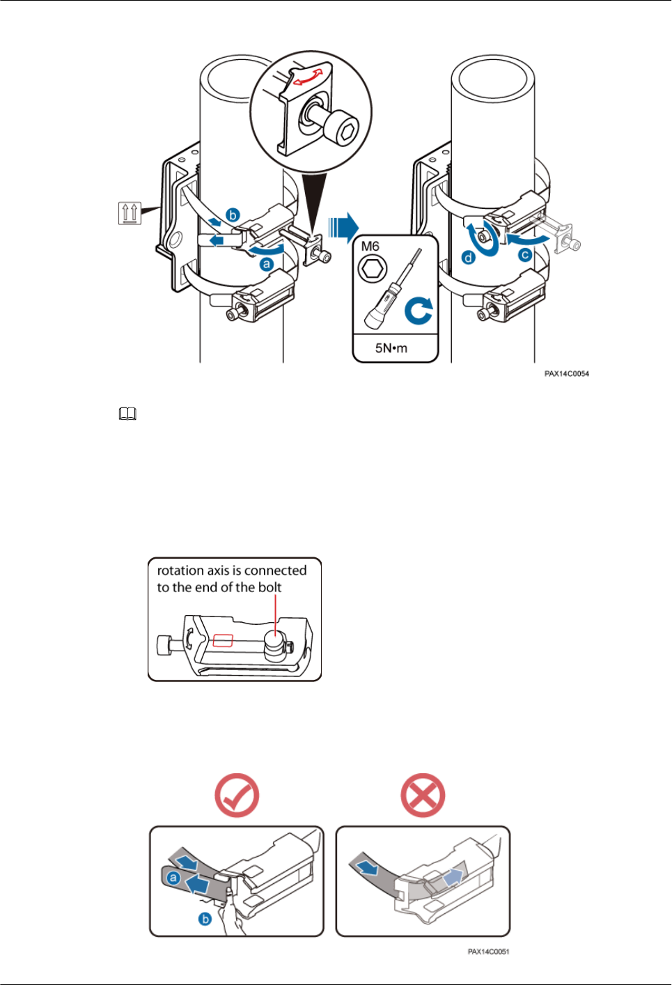
Figure 1-10 Fitting the Mounting bracket onto the target pole
NOTE
Redundant steel belts must be bound.
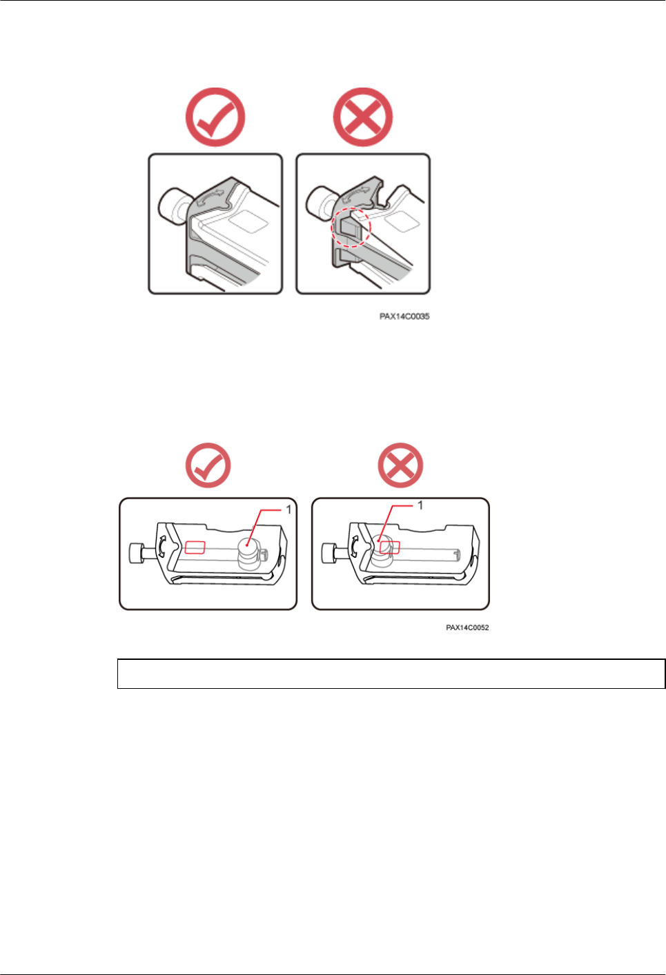
1. Open the bolt on each steel belt according to the arrow direction on the mounting base,
and ensure that the rotation axis is connected to the end of the bolt, as shown in Figure
1-11.
Figure 1-11 Position of the rotation axis
2. Partially tighten each steel belt with the force not less than 50 N, bend it by 180°, and
press the steel belt at turns firmly. See Figure 1-12.
Figure 1-12 Tighten steel belts
RRU3931E
Installation Guide 1 RRU3931E Installation Guide
Issue Draft A (2016-03-30) Huawei Proprietary and Confidential
Copyright © Huawei Technologies Co., Ltd.
15
3. Restore the bolt in position on the mounting base of the steel belt. See Figure 1-13.
Figure 1-13 Restoring the bolt in position on the mounting base
4. Use an M6 hex key screwdriver to torque the bolts to 7 N·m.
Check the steel belt installation status from the visible window. If the rotation axis is close to
the end of the bolt, remove the steel belt and fasten it again. See Figure 1-13.
Figure 1-14 Check the rotation axis status
(1) Rotation axis
Step 3 Fit the RRU3931E onto the Mounting bracket, and use an M6 hex key screwdriver to torque
the screw to 5 N·m. See Figure 1-15.
RRU3931E
Installation Guide 1 RRU3931E Installation Guide
Issue Draft A (2016-03-30) Huawei Proprietary and Confidential
Copyright © Huawei Technologies Co., Ltd.
16
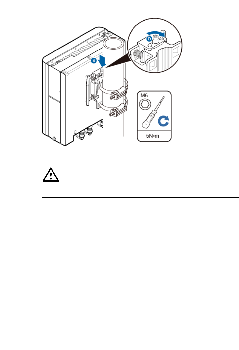
Figure 1-15 Fitting a RRU3931E onto a Mounting bracket
NOTICE
Gently take and fit the RRU3931E onto the Mounting bracket.
----End
1.6.3 Installing a RRU3931E on a Wall
This section describes the procedure and precautions for installing a RRU3931E on a wall.
Procedure
Step 1 Place the Mounting bracket against the wall, use a level to verify that the mounting bracket is
placed horizontally, and use a marker to mark anchor points. See Figure 1-16.
RRU3931E
Installation Guide 1 RRU3931E Installation Guide
Issue Draft A (2016-03-30) Huawei Proprietary and Confidential
Copyright © Huawei Technologies Co., Ltd.
17
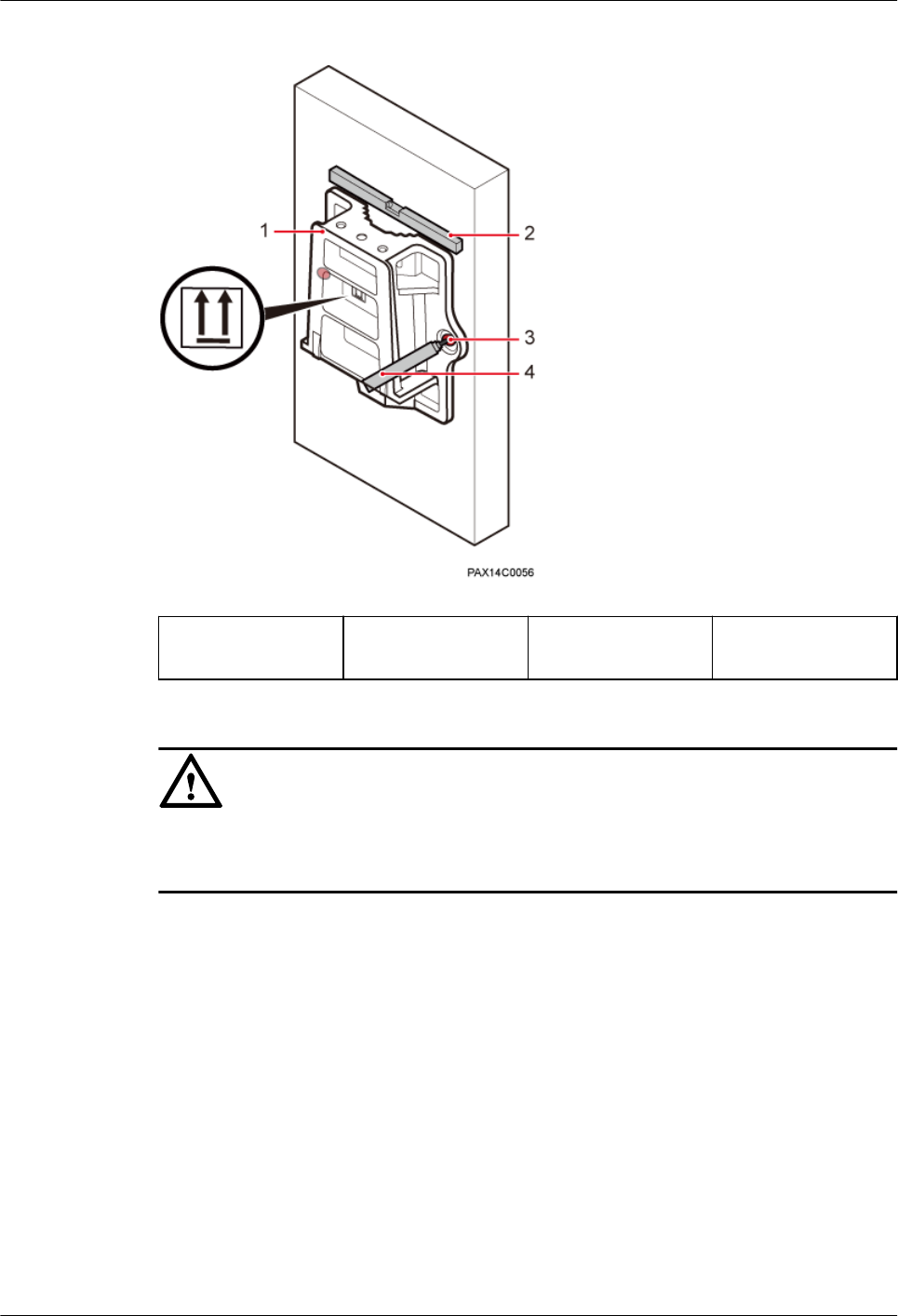
Figure 1-16 Marking anchor points
(1) Mounting
bracket
(2) Level (3) Mounting holes (4) Marker
NOTICE
To prevent inhalation or eye contact with dust, take adequate preventive measures when
drilling holes.
Step 2 Drill holes at the anchor points, and install expansion bolts. See Figure 1-17.
RRU3931E
Installation Guide 1 RRU3931E Installation Guide
Issue Draft A (2016-03-30) Huawei Proprietary and Confidential
Copyright © Huawei Technologies Co., Ltd.
18
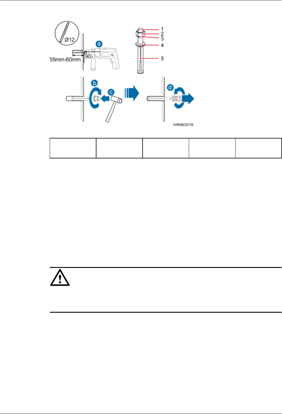
Figure 1-17 Drilling holes and installing expansion bolts
(1) M10x80
expansion bolt
(2) Nut (3) Spring
washer
(4) Flat washer (5) Expansion
sleeve
1. Use a hammer drill with Ф12 bore to drill holes vertically at the marked anchor points.
Ensure that the holes have the same depth ranging from 55 mm to 60 mm.
2. Use a vacuum cleaner to clear the dust from inside and around the holes, and measure
the inter-hole spacing. If the spacing is too wide or too narrow, relocate positions and
drill holes again.
3. Partially tighten an expansion bolt and vertically insert it into each hole.
4. Use a rubber mallet to hit the expansion bolts until the entire expansion sleeve is in each
hole.
5. Remove the M10×80 bolt, nut, spring washer, and flat washer in sequence.
NOTICE
Level the front of each expansion sleeve with the wall after disassembling an expansion bolt.
Otherwise, the mounting bracket will not be securely installed on the wall.
Step 3 Fit the Mounting bracket onto the wall through the four expansion bolts, and use an M10
socket wrench to torque the four expansion bolts to 28 N·m. See Figure 1-18.
RRU3931E
Installation Guide 1 RRU3931E Installation Guide
Issue Draft A (2016-03-30) Huawei Proprietary and Confidential
Copyright © Huawei Technologies Co., Ltd.
19
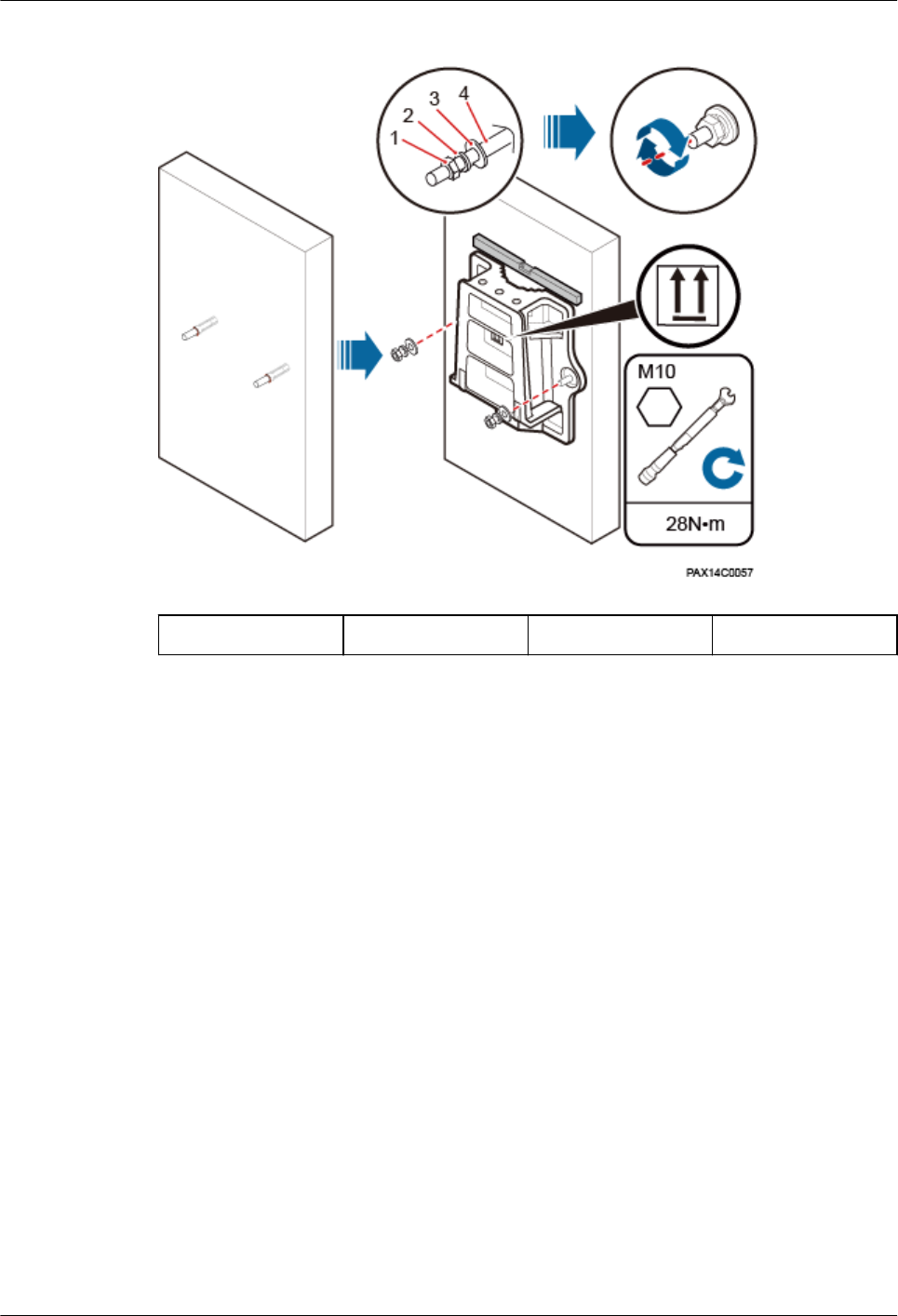
Figure 1-18 Fitting a Mounting bracket onto the wall
(1) Nut (2) Spring washer (3) Flat washer (4) Swell fixture
Step 4 Fit the RRU3931E onto the Mounting bracket, and use an M6 hex key screwdriver to torque
the screw to 5 N·m. See Figure 1-19.
RRU3931E
Installation Guide 1 RRU3931E Installation Guide
Issue Draft A (2016-03-30) Huawei Proprietary and Confidential
Copyright © Huawei Technologies Co., Ltd.
20
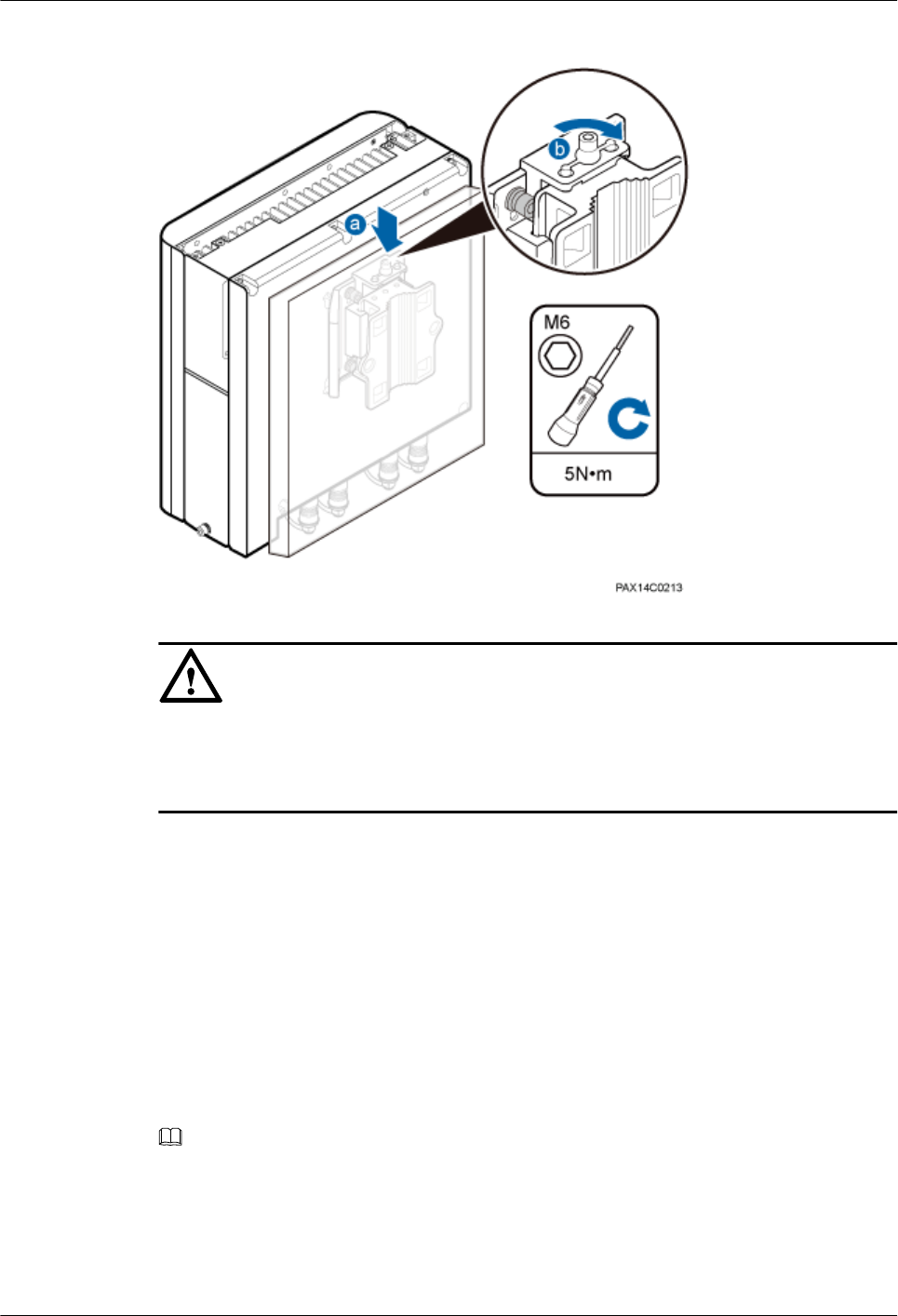
Figure 1-19 Fitting a RRU3931E onto a Mounting bracket
NOTICE
The narrow space of the RRU3931E toward the wall allows you only to fit the RRU3931E
onto the Mounting bracket in barehanded way, instead of using the attachment plate hander.
Do gently in the whole process.
----End
1.7 Installing Cables
This section describes the procedure and precautions for installing cables.
1.7.1 Cabling Requirements
Cables must be routed according to the specified cabling requirements to prevent interference
between signals.
NOTE
If a cable listed below is not required, skip the cabling requirements of the cable.
General Cabling Requirements
The bending radius of the cables must meet the following specifications:
RRU3931E
Installation Guide 1 RRU3931E Installation Guide
Issue Draft A (2016-03-30) Huawei Proprietary and Confidential
Copyright © Huawei Technologies Co., Ltd.
21

lThe bending radius of a 7/8'' feeder must be greater than 250 mm, and the bending radius
of a 5/4'' feeder must be greater than 380 mm.
lThe bending radius of a 1/4'' jumper must be greater than 35 mm. The bending radius of
a super-flexible 1/2'' jumper must be greater than 50 mm, and the bending radius of an
ordinary 1/2'' jumper must be greater than 127 mm.
lThe bending radius of a power cable or PGND cable must be at least five times its
diameter.
lThe bending radius of a fiber optic cable must be at least 20 times its diameter.
lThe bending radius of a signal cable must be at least five times its diameter.
The cables must be bound as follows:
lCables must be bound tightly and neatly. The sheaths of cables must not be damaged.
lCable ties must face the same direction, and those at the same horizontal line must be in
a straight line. The excess of cable ties must be cut off.
lLabels or nameplates must be attached to the cables after they are installed.
The cables must be routed as follows:
lCables of different types must be routed separately in an untangled and orderly fashion.
lCables of different types must be parallel to each other or separated by using dedicated
separators.
lCables must be routed away from sharp objects or wall burrs. If these positions are
inevitable, cables must be protected with protection pipes.
lCables must be routed away from heat sources, or heat-insulation materials must be
added between cables and heat sources.
lSufficient slack must be provided in cables at turns or the position close to a device,
facilitating cable and device maintenance. The recommended slack is 0.1 m.
lAC power cables and PGND cables must be tubed when routed.
lDrip loops must be reserved for cable layout at connection points and thru-wall points
indoors/outdoors.
lAll cables cannot be routed overhead. Cables laid out outdoors should be buried in the
ground.
Special Cabling Requirements
Power cables must be routed as follows:
lMultiple power cables must be bound when routed.
lPower cables must be installed in the positions specified in engineering design
documents.
lIf the length of power cables is insufficient, the power cables must be replaced instead of
adding connectors or soldering joints to lengthen the cables.
lCabling activities require strict organization and coordination, and are allowed only
when qualified personnel and communication facilities are available.
lCables must be routed in an untangled and orderly fashion.
lAC power cables must be tubed when routed.
PGND cables must be routed as follows:
RRU3931E
Installation Guide 1 RRU3931E Installation Guide
Issue Draft A (2016-03-30) Huawei Proprietary and Confidential
Copyright © Huawei Technologies Co., Ltd.
22

lPGND cables for a RRU3931E must be connected to the same ground bar.
lPGND cables must be buried in the ground or routed indoors. They must not be routed
overhead before they are led into the equipment room.
lThe exterior of a coaxial wire and the shield layer of a shielded cable must have proper
electrical contact with the metal surface of the equipment to which they are connected.
lPGND cables and signal cables must be bound separately in an untangled and orderly
fashion. A certain distance must be reserved between them to prevent mutual
interference.
lFuses or switches must not be installed on PGND cables.
lOther devices must not be used for electrical connections of PGND cables.
lAll the metal parts in the housing of the RRU3931E must be reliably connected to the
ground terminal.
lPGND cables must be tubed when routed.
Signal cables must be routed as follows:
lSignal cables must not cross power cables, PGND cables, or RF cables when routed. If
transmission cables are routed parallel to power cables, PGND cables, or RF cables, the
spacing between them must be greater than 30 mm.
lSignal cables must be routed straightly and bound neatly with cable ties.
lSufficient slack must be provided in signal cables at turns.
Fiber optic cables must be routed as follows:
lA minimum of three qualified and trained personnel are required to route fiber optic
cables.
lThe operating temperature of fiber optic cables ranges from -40oC to +60oC. If the
current temperature is out of the range, additional protection measures must be taken or
the cable routing must be changed.
lCables must be routed in an untangled and orderly fashion.
lFiber optic cables must not be bound at turns.
lFiber optic cables cannot be stretched with too much force or stepped on, and they must
be far away from sharp objects. Heavy objects cannot be placed on fiber optic cables.
lWhen fiber optic cables are routed, the excess of the cables must be coiled around
special devices, such as a fiber coiler.
lFiber optic cables must be coiled gently and must not be bent in a forcible manner.
lVacant optical connectors must be covered with dustproof caps.
lFiber optic cables cannot be squeezed by a cabinet door when routed through a cabinet.
lWhen routed on the tower platform, the fiber optic cables must be laid out along the
guardrail within the shortest distance.
lWhen routed close to a device on the tower, the fiber optic cables must be secured to the
guard rail or pole with cable clips. The RRU3931E must not be far away from the
position for securing the fiber optic cables.
lThe excess of the fiber optic cables must be coiled and secured on the tower.
1.7.2 Cable Connections
This section describes the connections of the canles.
Figure 1-20 shows the cable connections for a RRU3931E.
RRU3931E
Installation Guide 1 RRU3931E Installation Guide
Issue Draft A (2016-03-30) Huawei Proprietary and Confidential
Copyright © Huawei Technologies Co., Ltd.
23
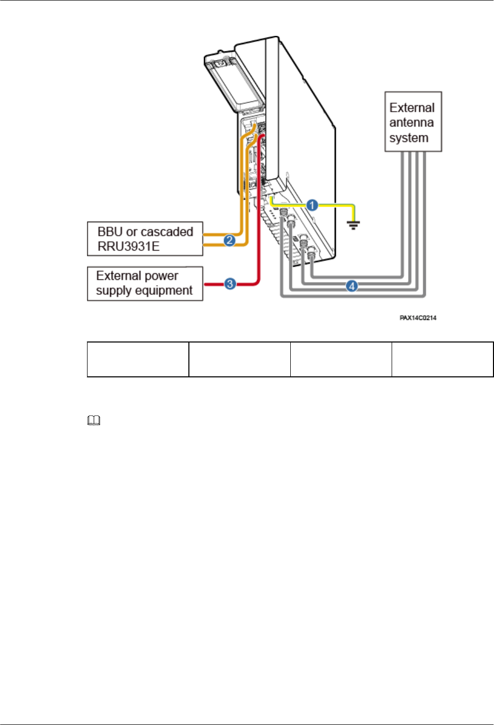
Figure 1-20 RRU3931E cable connections
(1) PGND cable (2) CPRI fiber optic
cable
(3) Power cable (4) RF Jumper
NOTE
When routing cables from a maintenance cavity, observe the following:
lRoute the power cable through the cable hole on the upper-layer rubber strip
lRoute the other cables (except power cables) through cable holes on the lower-layer rubber strip
preferentially
lRoute cables through cable holes on the same side of ports, and do not cross cables.
1.7.3 Opening the Maintenance Cavity Covers
This section describes the procedure and precautions for opening the maintenance cavity
covers of a RRU3931E.
Procedure
Step 1 Use an M6 hex key screwdriver to loosen the captive screw on both the maintenance cavity
covers. Open the maintenance cavity covers.
Figure 1-21 shows the maintenance cavity structure.
RRU3931E
Installation Guide 1 RRU3931E Installation Guide
Issue Draft A (2016-03-30) Huawei Proprietary and Confidential
Copyright © Huawei Technologies Co., Ltd.
24
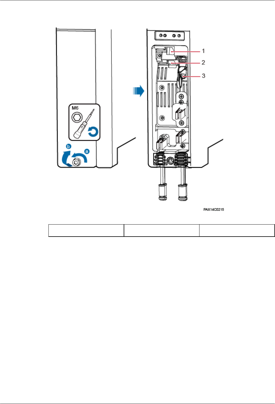
Figure 1-21 Maintenance cavity structure
(1) CPRI1 (2) CPRI0 (3) PWR
Step 2 Remove the waterproof blocks for the cables to be installed.
----End
1.7.4 Installing a Power Cable
This section describes the procedure and precautions for installing a power cable for a
RRU3931E. The power cable connects the RRU3931E and external power supply equipment.
Context
Table 1-2 lists the specifications of a power cable.
RRU3931E
Installation Guide 1 RRU3931E Installation Guide
Issue Draft A (2016-03-30) Huawei Proprietary and Confidential
Copyright © Huawei Technologies Co., Ltd.
25

Table 1-2 Power cable specifications
Cable Color One End The Other
End
Remarks
Input power
cable for a
RRU3931E
L Brown AC-EPC1
connector
Depends on
the external
power
supply
equipment.
Black jacket
N Blue
PE Yellow and
green
NOTE
The color and structure of a power cable varies with countries and regions. A locally purchased power
cable must be a pure copper outdoor three-core cable that has a cross-sectional area of 1.5 mm2 to 2.5
mm2 and a maximum outer diameter of 8.9 mm to 10.2 mm and complies with local specifications.
Procedure
Step 1 Make a power cable.
lCut the cable to a length suitable for the actual cable route.
lAdd a cord end terminal to one end of the cable by following instructions provided in
section 1.11.4 Assembling a Tool-less Female Connector (Pressfit Type) and a Power
Cable1.11.4 Assembling a Tool-less Female Connector (Pressfit Type) and a Power
Cable. At the other end, add a terminal that matches the external power supply
equipment.
Step 2 Installing the power cable. Connect the terminal of the power cable to the PWR port on the
RRU3931E. See Figure 1-22.
RRU3931E
Installation Guide 1 RRU3931E Installation Guide
Issue Draft A (2016-03-30) Huawei Proprietary and Confidential
Copyright © Huawei Technologies Co., Ltd.
26
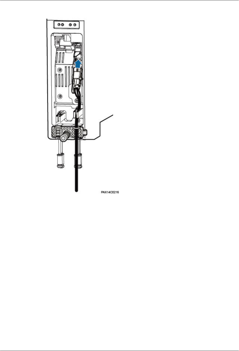
Figure 1-22 Installing a power cable
----End
Follow-up Procedure
1. Route the cable by following instructions provided in section 1.7.1 Cabling
Requirements"1.7.1 Cabling Requirements" and then use cable ties to bind the cable.
2. Attach labels to the installed cables by following instructions in 1.11.6 Attaching a Sign
Plate Label.
1.7.5 Installing an CPRI Fiber Optic Cable
This section describes the procedure and precautions for installing an CPRI fiber optic cable.
Context
lThe single-mode optical modules to be installed must match the data rate at the optical
ports.
lDo not twist, bend, stretch, or squeeze fiber optic cables during installation.
lThe cable route depends on actual requirements.
RRU3931E
Installation Guide 1 RRU3931E Installation Guide
Issue Draft A (2016-03-30) Huawei Proprietary and Confidential
Copyright © Huawei Technologies Co., Ltd.
27
NOTICE
Long-time exposure to the air causes performance exceptions on an optical module.
Therefore, optical modules must be connected to fiber optic cables within 20 minutes
after being unpacked.
Procedure
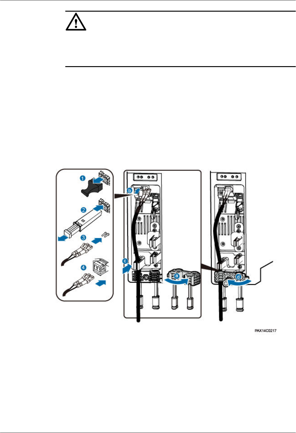
Step 1 Remove the dustproof cap from the CPRI0 or CPRI1 port. Keep the cap secure.
Step 2 Insert an optical module into the CPRI0 or CPRI1 port, and remove the dustproof cap from
the optical module.
Step 3 Remove the dustproof cap from the optical fiber connector, tidy the optical fibers, and insert
the DLC connector into the optical module. See Figure 1-23.
Figure 1-23 Installing a fiber optic cable
----End
Follow-up Procedure
1. Route the cable by following instructions provided in section 1.7.1 Cabling
Requirements"1.7.1 Cabling Requirements" and then use cable ties to bind the cable.
2. Attach labels to the installed cables by following instructions in 1.11.6 Attaching a Sign
Plate Label.
RRU3931E
Installation Guide 1 RRU3931E Installation Guide
Issue Draft A (2016-03-30) Huawei Proprietary and Confidential
Copyright © Huawei Technologies Co., Ltd.
28
1.7.6 (Optional) Installing an CPRI Fiber Optic Cable for
Cascading
This section describes the procedure and precautions for installing an CPRI fiber optic cable
used for cascading two RRU3931Es.
Context
lThe single-mode optical modules to be installed must match the data rate at the optical
ports.
lDo not twist, bend, stretch, or squeeze fiber optic cables during installation.
lThe cable route depends on actual requirements.
NOTICE
Long-time exposure to the air causes performance exceptions on an optical module.
Therefore, optical modules must be connected to fiber optic cables within 20 minutes
after being unpacked.
Procedure
Step 1 For both RRU3931Es, remove the dustproof cap from the CPRI0 or CPRI1 port. Keep the cap
secure.
Step 2 For both RRU3931Es, insert an optical module into the CPRI0 or CPRI1 port, and remove the
dustproof cap from the optical module.
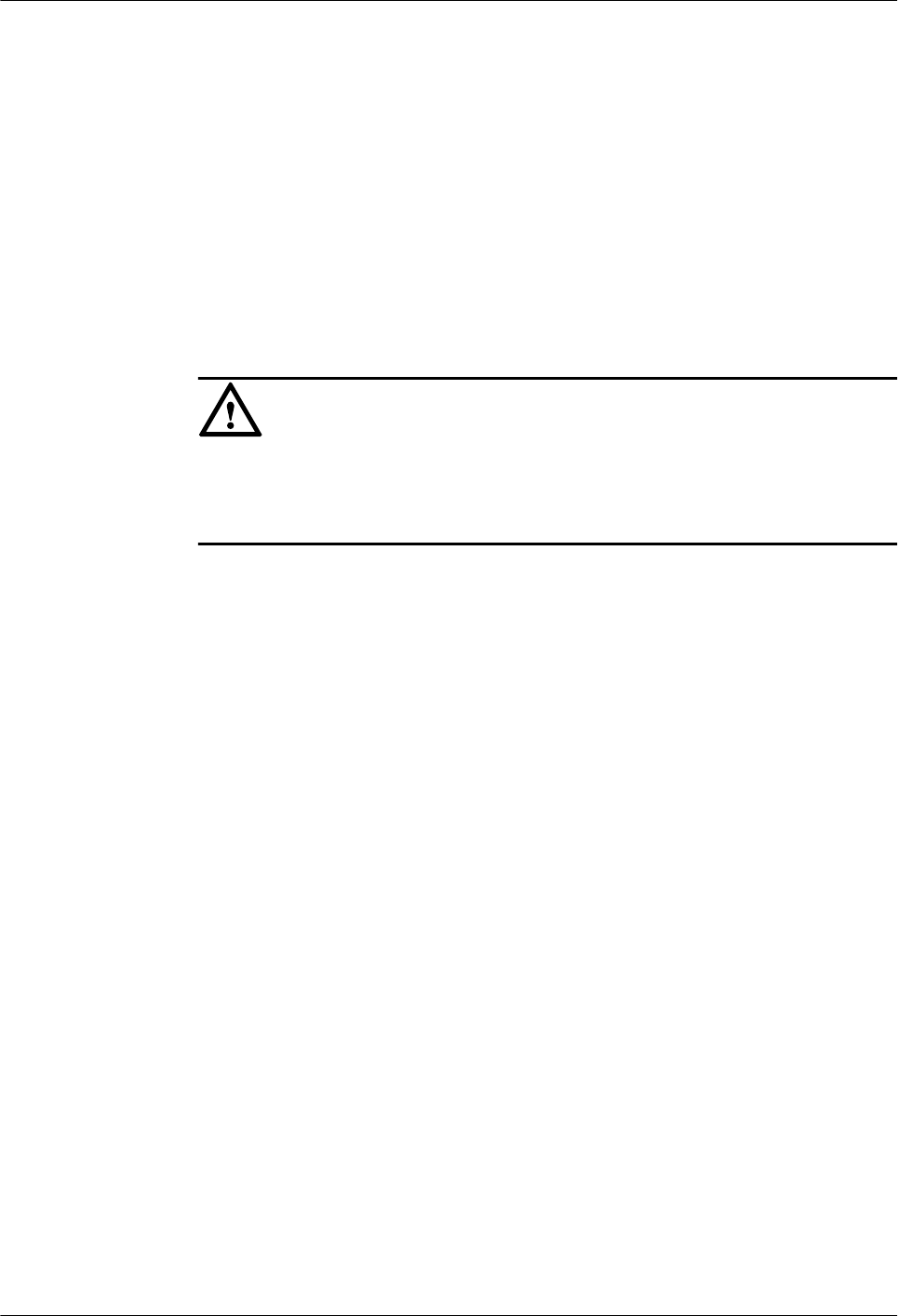
Step 3 Remove the dustproof cap from the optical fiber connector, tidy the optical fibers, and insert
the DLC connector into the optical module. See Figure 1-24.
RRU3931E
Installation Guide 1 RRU3931E Installation Guide
Issue Draft A (2016-03-30) Huawei Proprietary and Confidential
Copyright © Huawei Technologies Co., Ltd.
29
Figure 1-24 Installing a fiber optic cable for cascading
----End
Follow-up Procedure
1. Route the cable by following instructions provided in section 1.7.1 Cabling
Requirements"1.7.1 Cabling Requirements" and then use cable ties to bind the cable.
2. Attach labels to the installed cables by following instructions in 1.11.6 Attaching a Sign
Plate Label.
1.7.7 Closing the Maintenance Cavity Covers
This section describes the procedure and precautions for closing the maintenance cavity
covers of a RRU3931E.
Procedure
Step 1 Insert waterproof blocks into vacant cable troughs in both the cabling holes. See Figure 1-25.
CAUTION
Ensure that cables or waterproof blocks are properly inserted into troughs.
RRU3931E
Installation Guide 1 RRU3931E Installation Guide
Issue Draft A (2016-03-30) Huawei Proprietary and Confidential
Copyright © Huawei Technologies Co., Ltd.
30
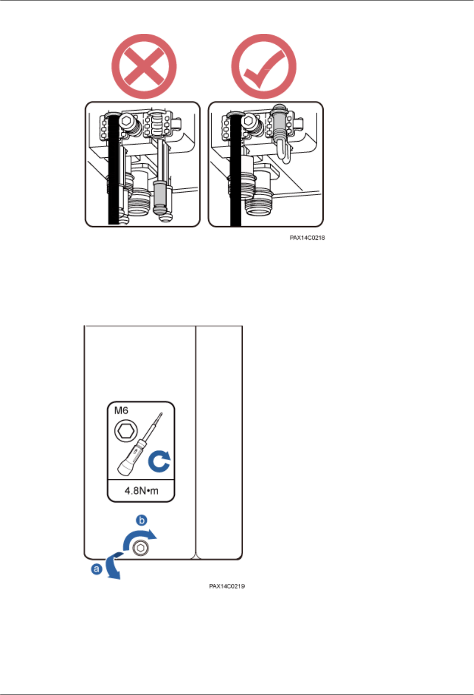
Figure 1-25 Checking that vacant cable troughs are properly waterproofed
Step 2 Close the maintenance cavity covers of the RRU3931E. Use an M6 hex key screwdriver to
torque the screws on the covers to 4.8 N·m. See Figure 1-26.
Figure 1-26 Closing the maintenance cavity covers
----End
1.7.8 Installing a PGND Cable
This section describes the procedure and precautions for installing a PGND cable.
RRU3931E
Installation Guide 1 RRU3931E Installation Guide
Issue Draft A (2016-03-30) Huawei Proprietary and Confidential
Copyright © Huawei Technologies Co., Ltd.
31
Context
The length of a PGND cable must not exceed 30 m. When the required PGND cable is longer
than 30 m, deploy the ground bar nearer the RRU3931E. Table 1-3
Table 1-3 PGND cable specifications
Cable One End The Other End Color
PGND cable OT terminal (M6, 6
mm2)
OT terminal (M8, 6
mm2)
Yellow and green
rocedure
Step 1 Make a PGND cable for the RRU3931E.
lCut the cable to the required length based on the actual cable route.
lAdd an OT terminal to each end of the PGND cable by following instructions provided
in section "Assembling the OT Terminal and the Power Cable" of Installation Reference.
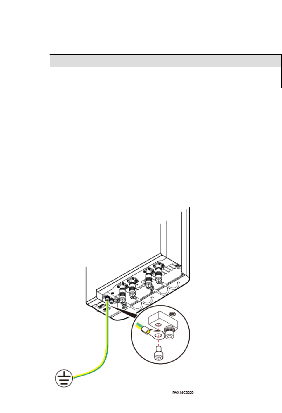
Step 2 Install the PGND cable.
Connect the M6 OT terminal at one end of the PGND cable to the ground terminal at the
RRU3931E bottom and the M8 OT terminal at the other end to the external ground bar. See
Figure 1-27.
Figure 1-27 Installing a PGND cable
RRU3931E
Installation Guide 1 RRU3931E Installation Guide
Issue Draft A (2016-03-30) Huawei Proprietary and Confidential
Copyright © Huawei Technologies Co., Ltd.
32
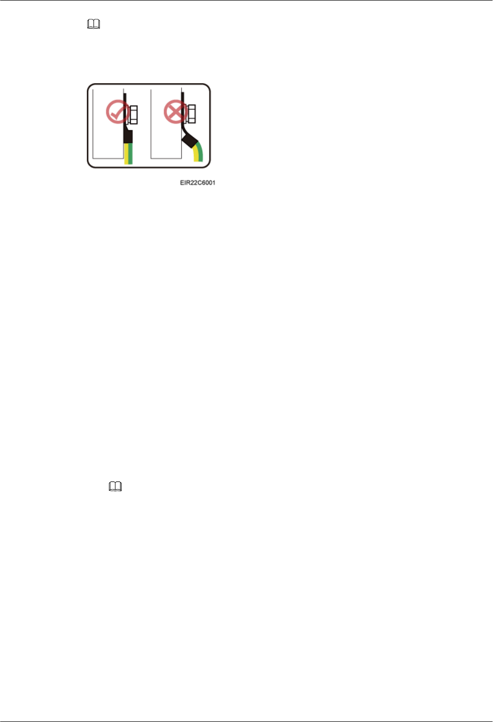
NOTE
When installing the PGND cable, crimp OT terminals in correct positions. See Figure 1-28.
Figure 1-28 Crimping an OT terminal
----End
Follow-up Procedure
1. Route the cable by following instructions provided in section 1.7.1 Cabling
Requirements"1.7.1 Cabling Requirements" and then use cable ties to bind the cable.
2. Attach labels to the installed cables by following instructions in 1.11.6 Attaching a Sign
Plate Label.
1.7.9 (Optional) Installing an RF Jumper
This section describes how to install an RF jumper for a RRU3931E. This operation is
required when the RRU3931E uses an external antenna.
Context
lThe cable route depends on actual requirements.
lThe RRU3931E RF jumper can connect the RRU3931E and external antenna system, or
connect the RRU3931E and GPS antenna system. The following section takes installing
an RF jumper between the RRU3931E and external antenna system as an example.
NOTE
It is good practice to use an RF jumper when installing the external antenna system for the
RRU3931E. If the RRU3931E RF jumper is not used, install the antenna on the RRU3931E
through the normal type N female connector, and waterproof the connector by following
instructions provided in Step 5.
Procedure
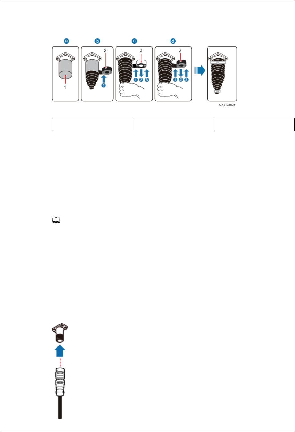
Step 1 Remove the plastic waterproof cap from the RF port. See Figure 1-29.
RRU3931E
Installation Guide 1 RRU3931E Installation Guide
Issue Draft A (2016-03-30) Huawei Proprietary and Confidential
Copyright © Huawei Technologies Co., Ltd.
33
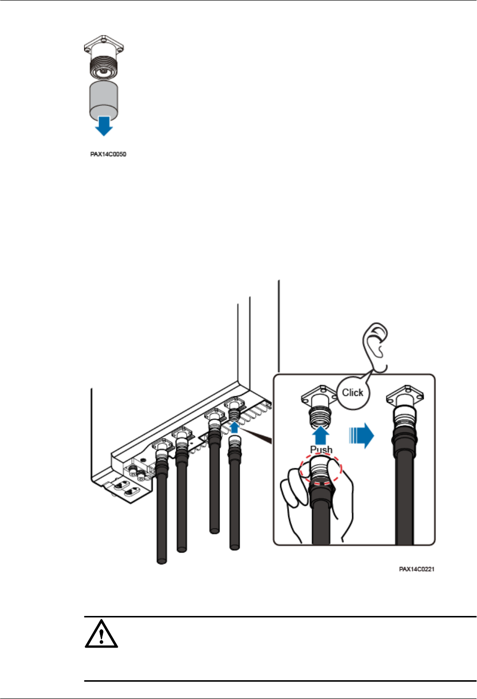
Figure 1-29 Removing a waterproof cap
Step 2 Connect the Smart-type N male connector at one end of the RF jumper to the RF port on the
RRU3931E.
When installing an RF jumper, hold tightly the metal part (in the red dotted circle in Figure
1-30) of the Smart-type N male connector and push the connector upwards. A slight crack
will be heard when the connector is properly installed. See Figure 1-30.
Figure 1-30 Installing an RF jumper
NOTICE
Do not exert force on the non-metal part, that is, the black part, as shown in Figure 1-30
RRU3931E
Installation Guide 1 RRU3931E Installation Guide
Issue Draft A (2016-03-30) Huawei Proprietary and Confidential
Copyright © Huawei Technologies Co., Ltd.
34
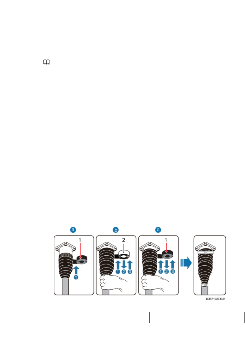
Step 3 (Optional) If an RF port is not used, retain and waterproof the waterproof cap on the port.
Figure 1-31 Waterproofing a waterproof cap
(1) Waterproof cap (2) PVC insulation tape (3) Waterproof tape
1. Verify that waterproof caps are not removed.
2. Wrap a layer of PVC insulation tape around the connector from bottom up.
3. Tightly wrap three layers of waterproof tape around the connector, with the first layer
from bottom up, the second layer from top down, and the third layer from bottom up.
4. Tightly wrap three layers of PVC insulation tape around the connector with the first layer
from bottom up, the second layer from top down, and the third layer from bottom up.
5. Bundle cable ties 3 mm to 5 mm away from the end of insulating tape.
NOTE
lBefore wrapping waterproof tape, stretch the tape evenly until the length of the tape is twice its
original length.
lDo not stretch the PVC insulation tape before wrapping.
lWrap each layer of tape around the connector tightly and neatly, and ensure that each layer of tape
overlaps more than 50% of the preceding layer
lEnsure that the side with adhesive tape is covered on the wrapped tape.
lWhen cutting off the cable tie, reserve a surplus length of 3 mm to 5 mm.
Step 4 Connect the type N male connector at the other end of the RRU3931E RF jumper to the RF
port on the external antenna system. See Figure 1-32.
Figure 1-32 Connecting an RF jumper to the external antenna system
RRU3931E
Installation Guide 1 RRU3931E Installation Guide
Issue Draft A (2016-03-30) Huawei Proprietary and Confidential
Copyright © Huawei Technologies Co., Ltd.
35
Step 5 Wrap the connector of the RF jumper. See Figure 1-33.
Figure 1-33 Wrapping the connector of an RF jumper
(1) PVC insulation tape (2) Waterproof tape
1. Wrap a layer of PVC insulation tape around the connector from bottom up.
2. Tightly wrap three layers of waterproof tape around the connector, with the first layer
from bottom up, the second layer from top down, and the third layer from bottom up.
3. Tightly wrap three layers of PVC insulation tape around the connector, with the first
layer from bottom up, the second layer from top down, and the third layer from bottom
up.
4. Bundle cable ties 3 mm to 5 mm away from the end of the PVC insulation tape.
NOTE
lBefore wrapping waterproof tape, stretch the tape evenly until the length of the tape is twice its
original length.
lDo not stretch the PVC insulation tape before wrapping.
lWrap each layer of tape around the connector tightly and neatly, and ensure that each layer of tape
overlaps more than 50% of the preceding layer
lEnsure that the side with adhesive tape is covered on the wrapped tape.
lWhen cutting off the cable tie, reserve a surplus length of 3 mm to 5 mm.
----End
Follow-up Procedure
1. Route the cable by following instructions provided in section 1.7.1 Cabling
Requirements"1.7.1 Cabling Requirements" and then use cable ties to bind the cable.
2. Attach labels to the installed cables by following instructions in 1.11.6 Attaching a Sign
Plate Label.
1.8 (Optional)Replacing the Internal Antenna with
External Antennas
This section describes how to replace the RRU3931E internal antenna with external antennas.
RRU3931E
Installation Guide 1 RRU3931E Installation Guide
Issue Draft A (2016-03-30) Huawei Proprietary and Confidential
Copyright © Huawei Technologies Co., Ltd.
36
Procedure
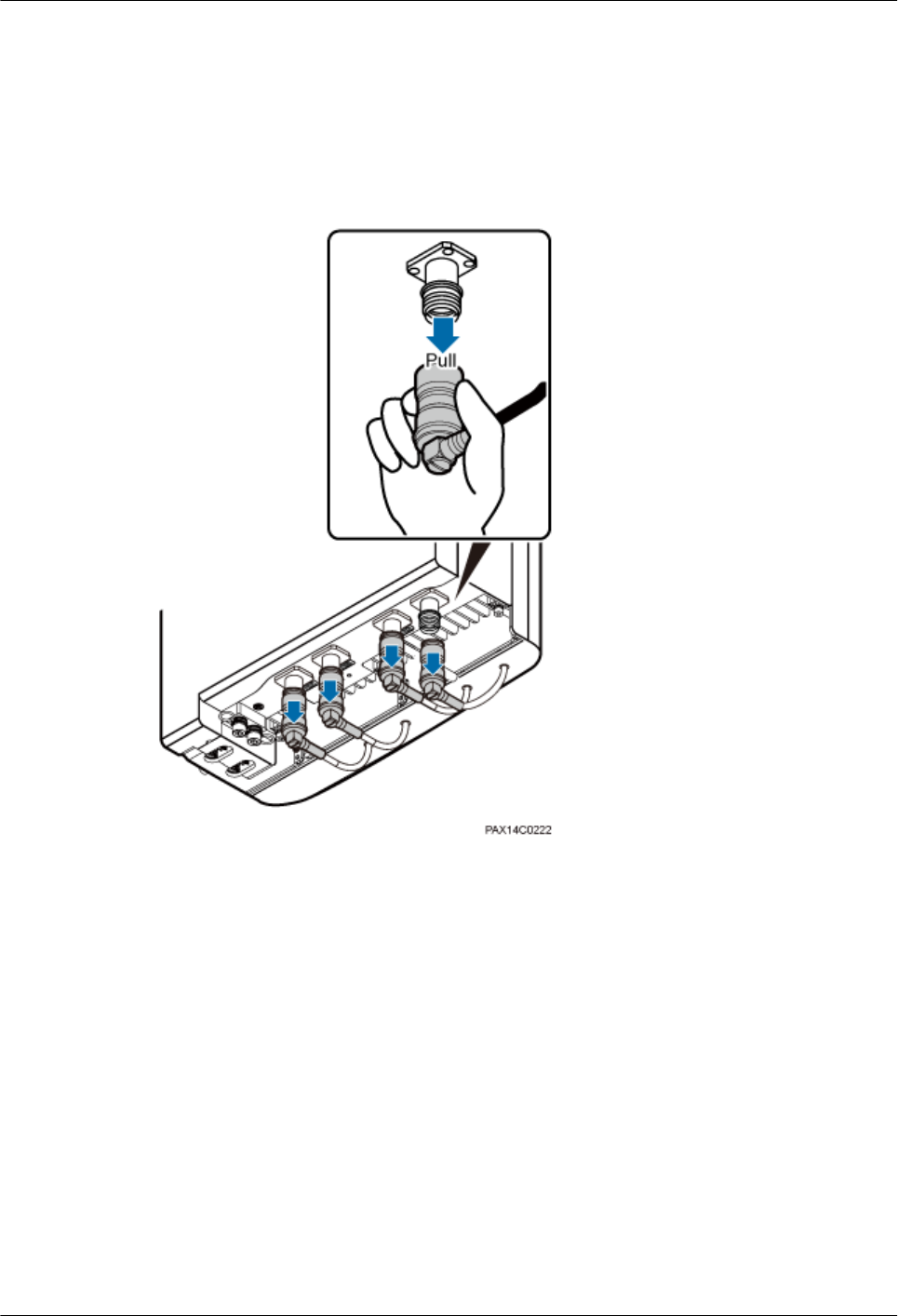
Step 1 Remove the RRU3931E antenna connector.
When removing a RRU3931E antenna connector, hold tightly the metal parts (red-marked
parts in Figure 1-34) of the antenna terminals, and pull down the terminals.
Figure 1-34 Removing the antenna connector
Step 2 Remove the screws from the antenna.
1. Use an M4 hex key to loosen the three M4x14 screws at the bottom of the RRU3931E.
2. Push the RRU3931E antenna downwards, as shown in Figure 1-35.
RRU3931E
Installation Guide 1 RRU3931E Installation Guide
Issue Draft A (2016-03-30) Huawei Proprietary and Confidential
Copyright © Huawei Technologies Co., Ltd.
37
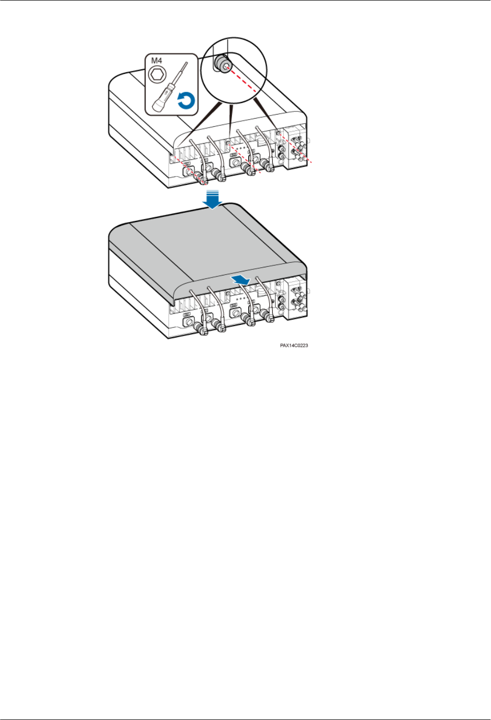
Figure 1-35 Removing screws
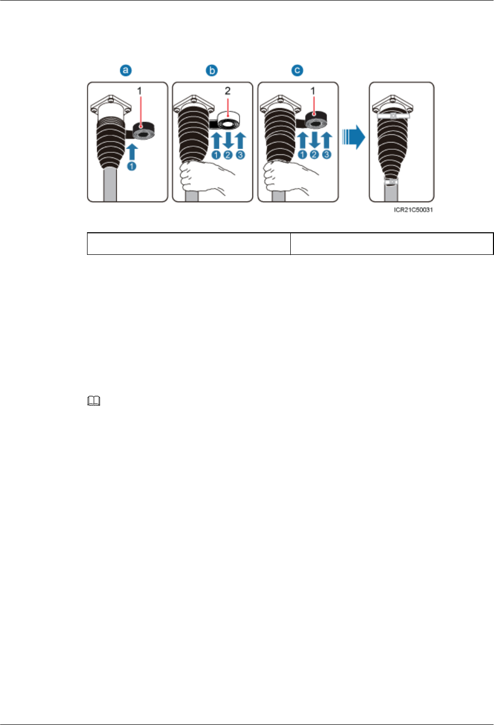
Step 3 Connect the Smart-type N male connector at one end of the RF jumper to the RF port on the
RRU3931E.
When installing an RF jumper, hold tightly the metal part (in the red dotted circle in Figure
1-36) of the Smart-type N male connector and push the connector upwards. A slight crack
will be heard when the connector is properly installed. See Figure 1-36.
RRU3931E
Installation Guide 1 RRU3931E Installation Guide
Issue Draft A (2016-03-30) Huawei Proprietary and Confidential
Copyright © Huawei Technologies Co., Ltd.
38
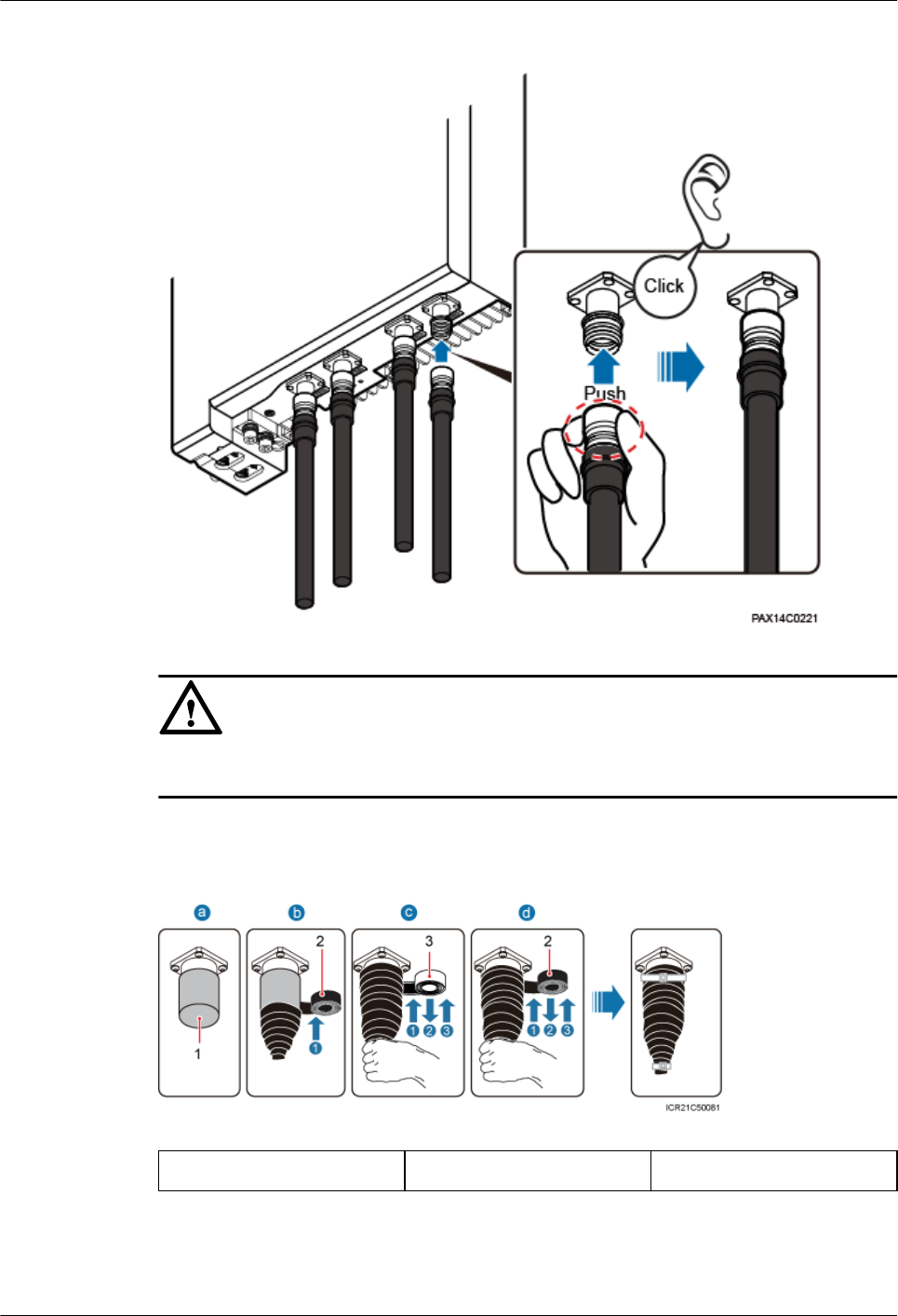
Figure 1-36 Installing an RF jumper
NOTICE
Do not exert force on the non-metal part, that is, the black part, as shown in Figure 1-36
Step 4 (Optional) If an RF port is not used, retain and waterproof the waterproof cap on the port.
Figure 1-37 Waterproofing a waterproof cap
(1) Waterproof cap (2) PVC insulation tape (3) Waterproof tape
1. Verify that waterproof caps are not removed.
RRU3931E
Installation Guide 1 RRU3931E Installation Guide
Issue Draft A (2016-03-30) Huawei Proprietary and Confidential
Copyright © Huawei Technologies Co., Ltd.
39
2. Wrap a layer of PVC insulation tape around the connector from bottom up.
3. Tightly wrap three layers of waterproof tape around the connector, with the first layer
from bottom up, the second layer from top down, and the third layer from bottom up.
4. Tightly wrap three layers of PVC insulation tape around the connector with the first layer
from bottom up, the second layer from top down, and the third layer from bottom up.
5. Bundle cable ties 3 mm to 5 mm away from the end of insulating tape.
NOTE
lBefore wrapping waterproof tape, stretch the tape evenly until the length of the tape is twice its
original length.
lDo not stretch the PVC insulation tape before wrapping.
lWrap each layer of tape around the connector tightly and neatly, and ensure that each layer of tape
overlaps more than 50% of the preceding layer
lEnsure that the side with adhesive tape is covered on the wrapped tape.
lWhen cutting off the cable tie, reserve a surplus length of 3 mm to 5 mm.
Step 5 (Optional) If a normal type N female connector is used for the antenna to be installed, perform
Step 4 to Step 5.
Step 6 (Optional) If the DIN-type female connector is used for the antenna to be installed, perform
the following steps:
1. Connect the DIN male and N female connector to the RF port of the external antenna
system.
2. Connect the type N male connector at one end of the RF jumper of the RRU3931E to the
DIN male and N female connector.
3. Waterproof the port connecting the DIN male and N female connector and the external
antenna system and the port connecting the RF jumper of the RRU3931E and the DIN
male and N female connector. See Figure 1-38.
Figure 1-38 Waterproofing the ports
(1) PVC insulation tape (2) Waterproof tape
a. Wrap a layer of PVC insulation tape around the connector from bottom up.
RRU3931E
Installation Guide 1 RRU3931E Installation Guide
Issue Draft A (2016-03-30) Huawei Proprietary and Confidential
Copyright © Huawei Technologies Co., Ltd.
40

b. Tightly wrap three layers of waterproof tape around the connector, with the first
layer from bottom up, the second layer from top down, and the third layer from
bottom up.
c. Tightly wrap three layers of PVC insulation tape around the connector, with the first
layer from bottom up, the second layer from top down, and the third layer from
bottom up.
d. Bundle cable ties 3 mm to 5 mm away from the end of the PVC insulation tape.
NOTE
– Before wrapping waterproof tape, stretch the tape evenly until the length of the tape is twice its
original length.
– Do not stretch the PVC insulation tape before wrapping.
– Wrap each layer of tape around the connector tightly and neatly, and ensure that each layer of
tape overlaps more than 50% of the preceding layer
– Ensure that the side with adhesive tape is covered on the wrapped tape.
– When cutting off the cable tie, reserve a surplus length of 3 mm to 5 mm.
----End
Follow-up Procedure
Route the cable by following instructions provided in section
1.7.1 Cabling Requirements, and then use cable ties to bind the cable.
1.9 Checking the Hardware Installation
This section describes how to check the hardware installation after a RRU3931E is installed.
Table 1-4 provides the checklist for the RRU3931E hardware installation.
Table 1-4 RRU3931E hardware installation checklist
SN Item
1 The installation position conforms to the engineering drawing and meets the
clearance requirements. Sufficient space is reserved for equipment
maintenance.
2 The RRU3931E is securely installed, and the screws are tightened.
3 In wall-mounted scenarios, the mounting holes on the mounting bracket are
well aligned with those of the expansion bolts. In addition, the mounting
bracket is secured on the wall evenly and steadily.
4 In pole-mounted scenarios, the mounting bracket is secured on the pole.
5 The angle adjustment error of the RRU3931E is less than 3° in the horizontal
direction and is not more than 3° in the vertical direction.
6 Vacant cable troughs in both maintenance cavities are covered with
waterproof blocks, and the maintenance cavity covers are fastened.
RRU3931E
Installation Guide 1 RRU3931E Installation Guide
Issue Draft A (2016-03-30) Huawei Proprietary and Confidential
Copyright © Huawei Technologies Co., Ltd.
41
SN Item
7 None of power cables and PGND cables are short-circuited, reversely
connected, damaged, or broken.
8 Power cables and PGND cables are separately bound from other cables.
9 All modules are connected using equipotential cables and then connected to
the closest ground bar by using PGND cables.
10 The connectors of each signal cable are intact and securely linked, and these
cables are not damaged or broken.
11 Labels are correct, legible, and complete at both ends of each cable.
1.10 Performing a Power-On Check
This section describes the procedure for performing a power-on check on a RRU3931E.
Context
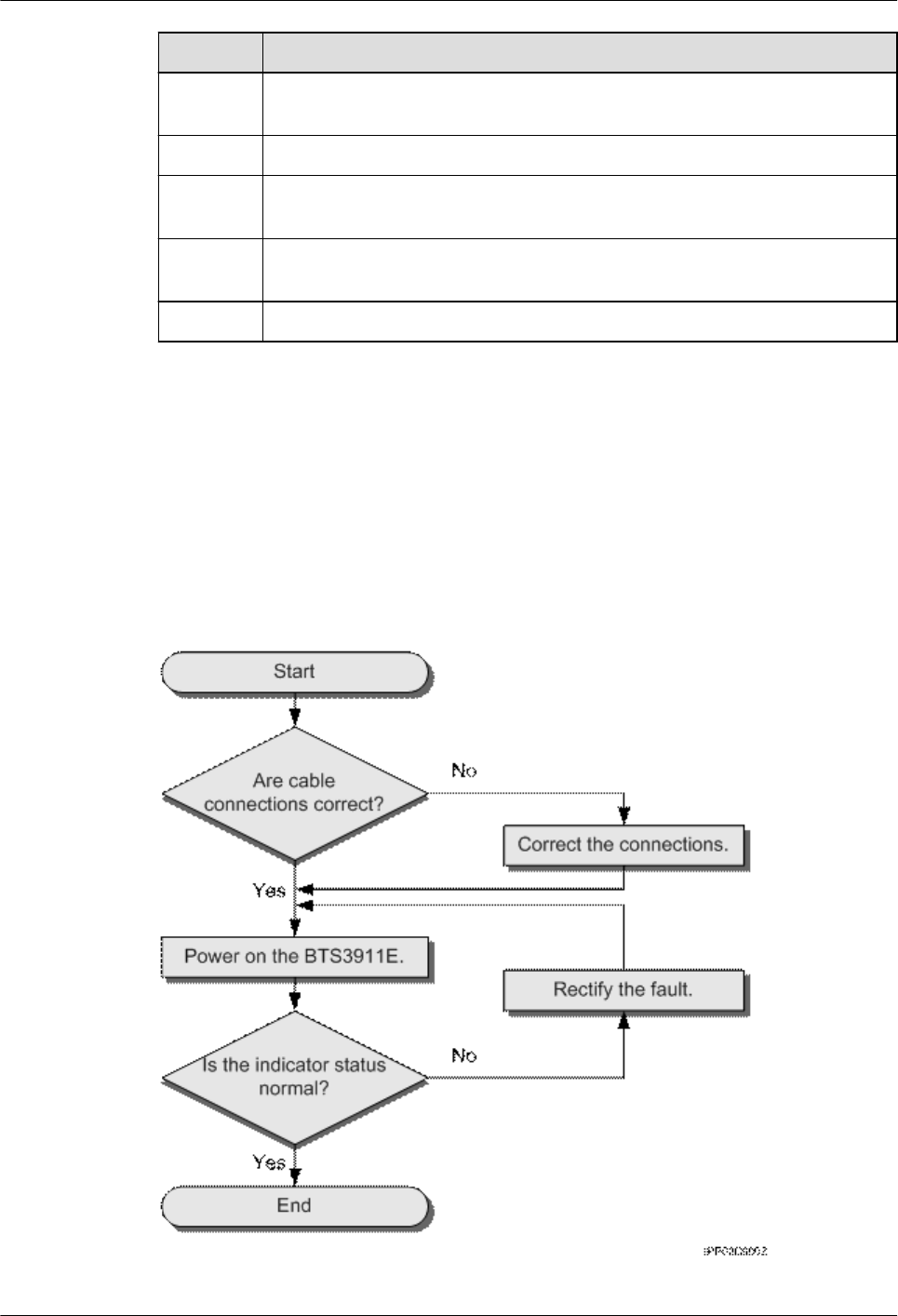
Figure 1-39 shows the RRU3931E power-on check procedure.
Figure 1-39 Power-on check
RRU3931E
Installation Guide 1 RRU3931E Installation Guide
Issue Draft A (2016-03-30) Huawei Proprietary and Confidential
Copyright © Huawei Technologies Co., Ltd.
42

Procedure
Step 1 Check that the cables are correctly connected.
Step 2 Check that the input voltage of the RRU3931E is 110 V AC to 240 V AC, and the frequency
ranges from 50 Hz to 60 Hz.
Step 3 Power on the RRU3931E. Wait 3 to 5 minutes and then observe the indicator status of the
RRU3931E. If the RUN indicator blinks (on for 1s and off for 1s) and the ALM indicator is
off, the RRU3931E is working properly.
NOTE
lA RRU3931E takes about 3 minutes to complete the startup procedure, during which the indicator
status is negligible.
lDuring a startup, a RRU3931E reads and writes the flash memory and therefore the indicators
blinking quickly may blink irregularly for 1s to 2s, which does not affect services.
----End
1.11 References
This section describes reference information and common operations involved during
installation.
1.11.1 Assembling a Shielded RJ45 Connector and an Ethernet
Cable
This section describes how to assemble a shielded RJ45 connector and an Ethernet cable. A
straight-through cable is used as an example.
Context
Figure 1-40 shows the components of an RJ45 connector and an Ethernet cable.
RRU3931E
Installation Guide 1 RRU3931E Installation Guide
Issue Draft A (2016-03-30) Huawei Proprietary and Confidential
Copyright © Huawei Technologies Co., Ltd.
43
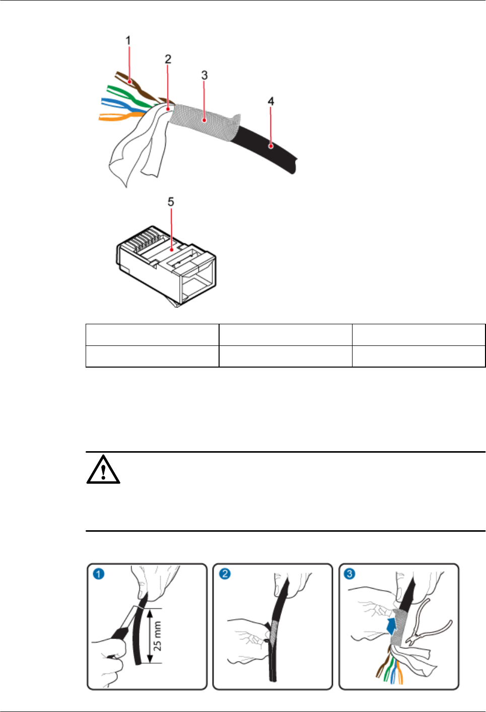
Figure 1-40 Components of an RJ45 connector and an Ethernet cable
(1) Core wire (2) Aluminum foil (3) Braided layer
(4) Outer jacket (5) RJ45 connector -
Procedure
Step 1 Remove the outer jacket (25 mm) of the Ethernet cable, tip the braided layer outwards evenly,
and cut off the aluminum foil and guard space. See Figure 1-41
NOTICE
lDo not damage the shield layer when removing the jacket.
lDo not damage the insulation layer of the Ethernet cable when removing the shield layer.
Figure 1-41 Removing the jacket of an Ethernet cable
RRU3931E
Installation Guide 1 RRU3931E Installation Guide
Issue Draft A (2016-03-30) Huawei Proprietary and Confidential
Copyright © Huawei Technologies Co., Ltd.
44
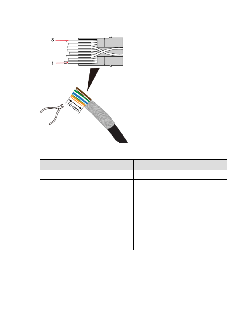
Step 2 Sequence the twisted pair wires neatly by color, and cut the wire end evenly, with a remaining
length of 16 mm. See Figure 1-42.
Figure 1-42 Arranging twisted pair wires
Table 1-5 Pin assignment
Pin SN Wire Color
1 White and orange
2 Orange
3 White and green
4 Blue
5 White and blue
6 Green
7 White and brown
8 Brown
Step 3 Insert the sequenced twisted pair wires into the RJ45 connector. See Figure 1-43.
RRU3931E
Installation Guide 1 RRU3931E Installation Guide
Issue Draft A (2016-03-30) Huawei Proprietary and Confidential
Copyright © Huawei Technologies Co., Ltd.
45
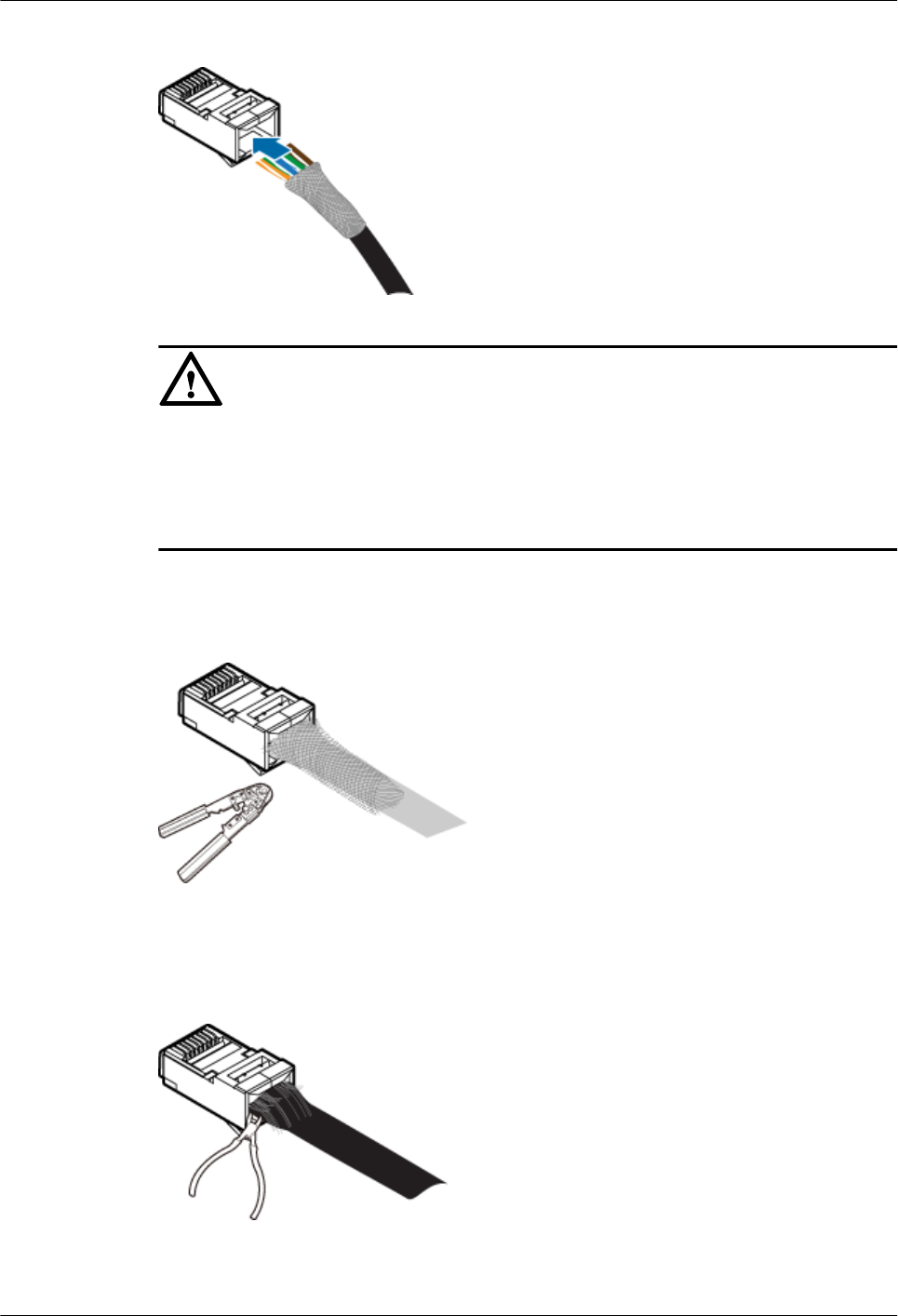
Figure 1-43 Inserting wires into the RJ45 connector
NOTICE
lWhen inserting the wires, ensure that the braided layer that was tipped outwards has
inserted inside the connector.
lObserve the side or front of the RJ45 connector to ensure that the core wires are inserted to
the bottom of the RJ45 connector.
Step 4 Use a crimping tool to crimp the connector. See Figure 1-44.
Figure 1-44 Crimping the connector
Step 5 Use a cable cutter to evenly cut off the protruding braided layer of the connector along the
wire holder. See Figure 1-45
Figure 1-45 Cutting off the excess braided layer
----End
RRU3931E
Installation Guide 1 RRU3931E Installation Guide
Issue Draft A (2016-03-30) Huawei Proprietary and Confidential
Copyright © Huawei Technologies Co., Ltd.
46
1.11.2 Checking the Appearance of Metal Contact Strips
This topic describes how to check the metal contact strips and how to check whether an
assembled RJ45 connector is qualified.
Context
lTo ensure proper contact between the crimped parts and the core wires, the heights and
sizes of the metal contact strips must be uniform and standard.
lThe metal contact strips must be parallel to each other, with an offset less than 5°. The
top margin of a strip must be parallel to the axis of the connector, with an offset less than
10°.
lTo ensure expedite conduction, the surface of the metal contact strips must be clean.
lThe metal contact strips must be in good contact with the RJ45 socket. The plastic septa
must remain intact and must be aligned properly.
lThe soldering edge of a metal contact strip must surpass the ends of the core wires. The
ends of the core wires must be in contact with the edge of the RJ45 trough. In principle,
the distance between them must be less than 0.5 mm (0.02 in.).
Procedure
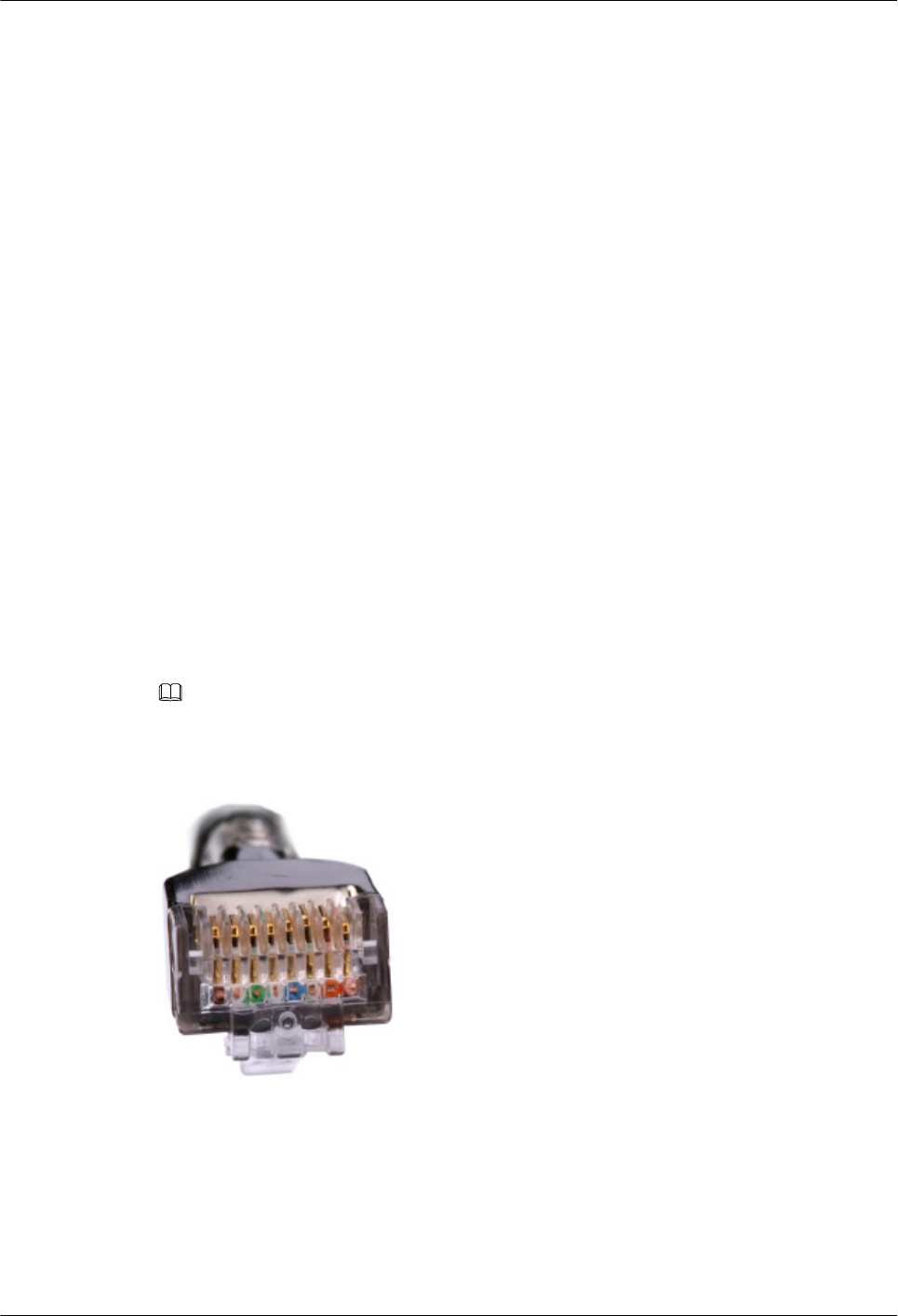
Step 1 Hold the crimped connector, with the front side facing you, and check whether the metal
contact strips are of the same height. In principle, the height is 6.02 mm (0.237 in.) ± 0.13 mm
(0.005 in.). If a measuring tool is not available, you can compare the connector with a
standard connector. Figure 1-46 shows an unqualified piece, and Figure 1-47 shows a
qualified piece.
NOTE
All unqualified pieces must be crimped again.
Figure 1-46 Metal contact strips of different heights
RRU3931E
Installation Guide 1 RRU3931E Installation Guide
Issue Draft A (2016-03-30) Huawei Proprietary and Confidential
Copyright © Huawei Technologies Co., Ltd.
47
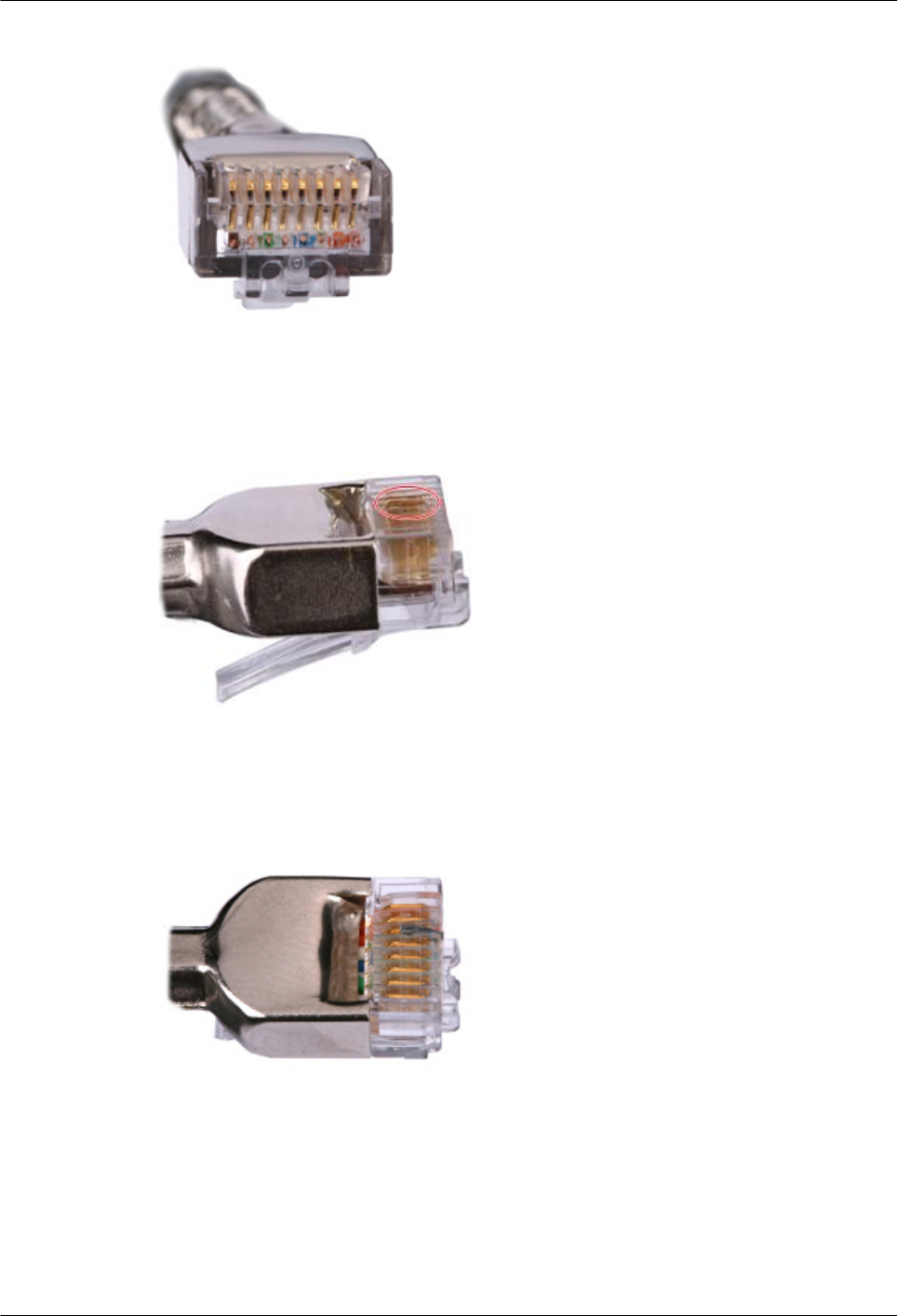
Figure 1-47 Metal contact strips of the same height
Step 2 Hold an RJ45 connector and turn it by 45°. Observe the top edges of the metal contact strips.
Figure 1-48 shows an unqualified piece.
Figure 1-48 Unparallel metal contact strips of different heights
Step 3 Check whether the metal contact strips are clean. If they are not clean and the dirt cannot be
removed, replace it with a new RJ45 connector. Figure 1-49 shows an unqualified piece.
Figure 1-49 Dirt on a metal contract strip
Step 4 Check whether the metal contact strips and the plastic septa are well aligned and intact. If a
part is skewed and it cannot be fixed, replace it with a new RJ45 connector. Figure 1-50
shows an unqualified piece.
RRU3931E
Installation Guide 1 RRU3931E Installation Guide
Issue Draft A (2016-03-30) Huawei Proprietary and Confidential
Copyright © Huawei Technologies Co., Ltd.
48
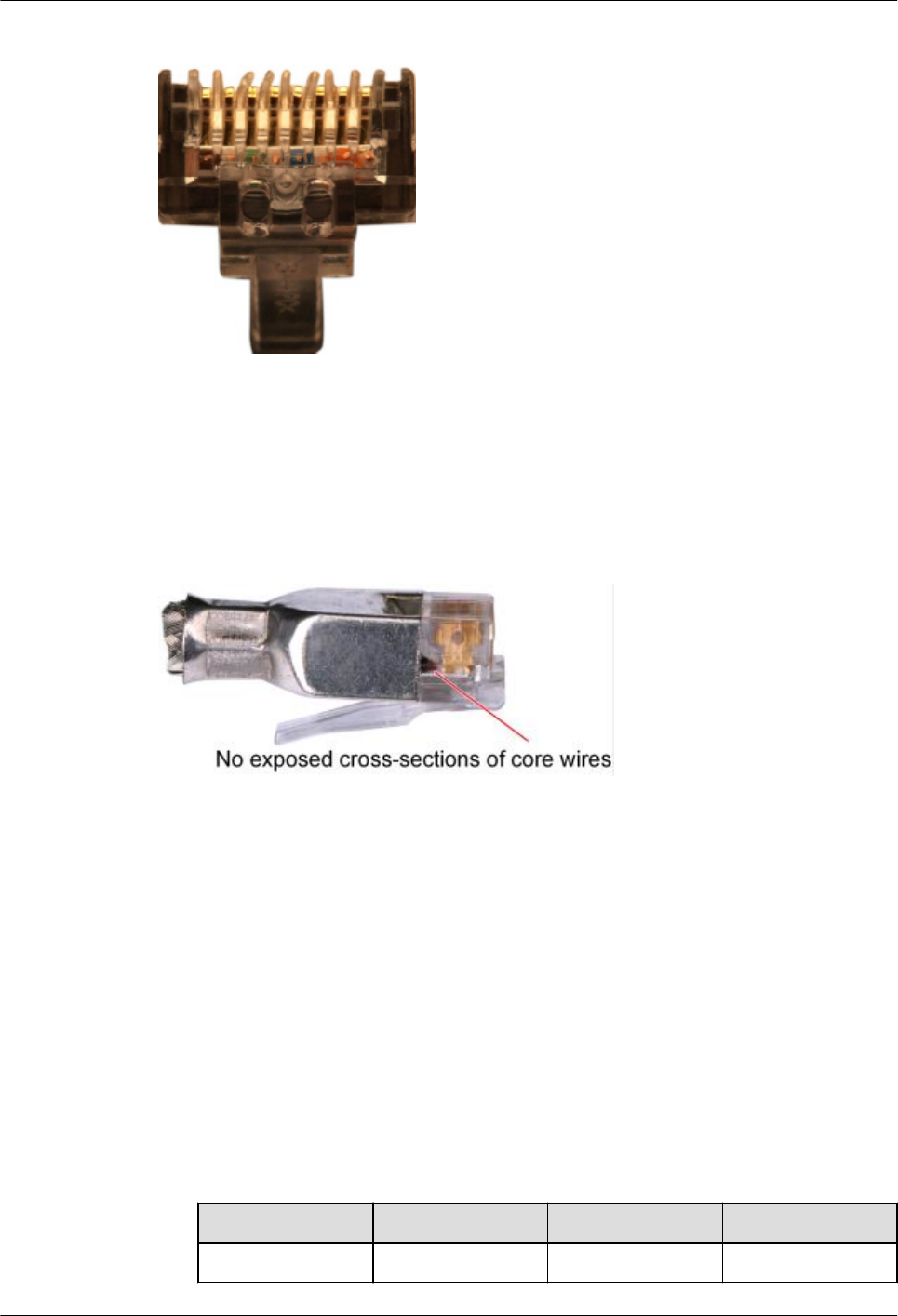
Figure 1-50 Skew plastic septa
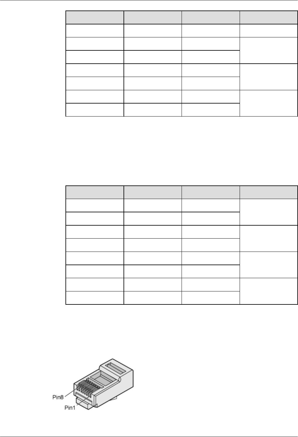
Step 5 Hold the connector, with the side facing towards you, and check whether you can see the
cross-sections of the core wires. Ensure that the ends of the core wires are in good contact
with the edge of the RJ45 trough, and that the soldering edge of a metal contact strip
surpasses the ends of the core wires and is reliably crimped with the core wires. If not, replace
it with a new RJ45 connector. Figure 1-51 shows an unqualified piece.
Figure 1-51 Core wires not in good contact with the edge of the RJ45 trough
----End
1.11.3 Testing the Connection of Assembled Cables
This topic describes how to test an assembled Ethernet cable, thus ensuring that the
connectors and wires at both ends are correctly connected. This topic illustrates how to test a
straight-through cable.
Context
Huawei provides two types of Ethernet cables: straight-through cables and crossover cables.
lStraight-through cables are connected in a one-to-one manner. They are used to connect
network adapters to equipment such as switches or hubs. Table 1-6 lists the connections
of core wires in a straight-through cable.
Table 1-6 Connections of core wires in a straight-through cable
RJ45 Connector 1 RJ45 Connector 2 Core Wire Color Twisted or Not
2 2 Orange Twisted
RRU3931E
Installation Guide 1 RRU3931E Installation Guide
Issue Draft A (2016-03-30) Huawei Proprietary and Confidential
Copyright © Huawei Technologies Co., Ltd.
49
RJ45 Connector 1 RJ45 Connector 2 Core Wire Color Twisted or Not
1 1 Orange-White
6 6 Green Twisted
3 3 Green-White
4 4 Blue Twisted
5 5 Blue-White
8 8 Brown Twisted
7 7 Brown-White
lCrossover cables are connected in a crossover manner. They are used to connect network
adapters to equipment such as switches or hubs. Table 1-7 lists the connections of core
wires in a crossover cable.
Table 1-7 Connections of core wires in a straight crossover cable
RJ45 Connector 1 RJ45 Connector 2 Core Wire Color Twisted or Not
6 2 Orange Twisted
3 1 Orange-White
2 6 Green Twisted
1 3 Green-White
4 4 Blue Twisted
5 5 Blue-White
8 8 Brown Twisted
7 7 Brown-White
Figure 1-52 shows the pins of an RJ45 connector.
Figure 1-52 Pins of an RJ45 connector
RRU3931E
Installation Guide 1 RRU3931E Installation Guide
Issue Draft A (2016-03-30) Huawei Proprietary and Confidential
Copyright © Huawei Technologies Co., Ltd.
50
Procedure
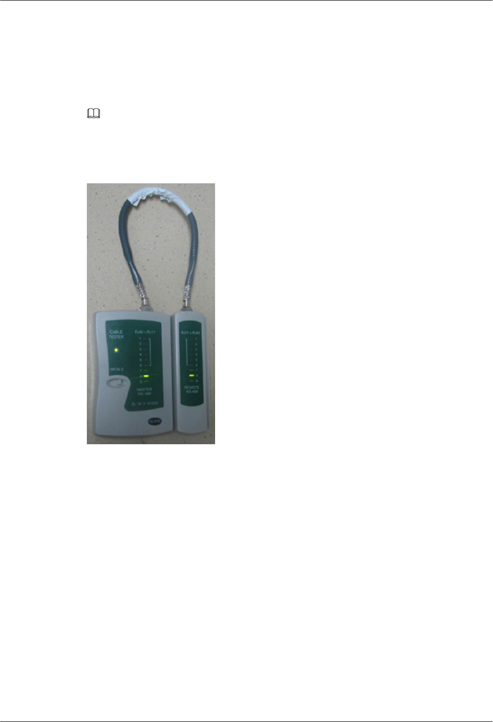
Step 1 Feed both connectors of the cable into the ports of the cable tester.
Step 2 After the connectors are properly inserted, turn on the tester. If the indicators from 1 to G turn
on simultaneously, you can infer that the pins work normally and the wires are correctly
connected.
NOTE
Turn the switch to the S position and check whether the indicators turn on simultaneously, as shown in
Figure 1-53.
Figure 1-53 Testing the conduction and connections of wires
Step 3 Gently shake the connector and repeat Step 2 to check whether the metal contact strips are in
good contact with the core wires and Ethernet ports, as shown in Figure 1-54.
RRU3931E
Installation Guide 1 RRU3931E Installation Guide
Issue Draft A (2016-03-30) Huawei Proprietary and Confidential
Copyright © Huawei Technologies Co., Ltd.
51
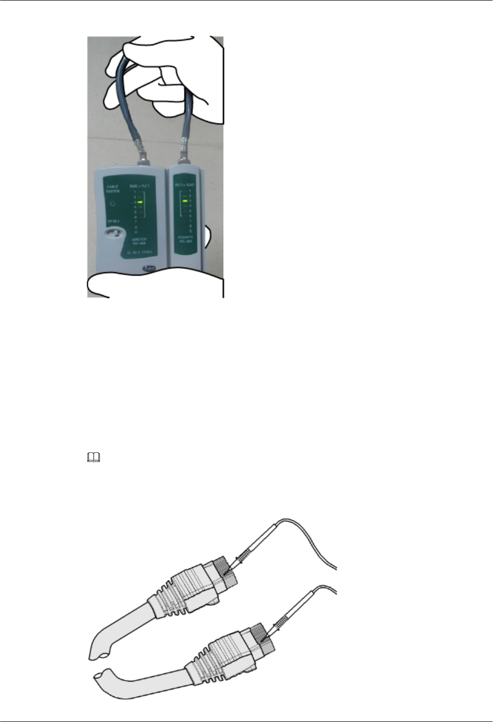
Figure 1-54 Checking the reliability
The procedure for testing a crossover cable is the same as that for testing a straight-through
cable except for the sequence in which the indicators turn on. You need to refer to the wire
connections of a crossover cable.
The Ethernet cable is qualified if the indicators turn on in the following sequence:
At the master (left) section of the tester, the indicators turn on in the sequence of 1-8-G. At the
slave (right) section of the tester, the indicators turn on in the sequence of 3-6-1-4-5-2-7-8-G.
Otherwise, the Ethernet cable is unqualified.
NOTE
If a tester is not available, you can use a multimeter to perform a simple test, as shown in Figure 1-55.
Figure 1-55 Testing the connection of an Ethernet cable
RRU3931E
Installation Guide 1 RRU3931E Installation Guide
Issue Draft A (2016-03-30) Huawei Proprietary and Confidential
Copyright © Huawei Technologies Co., Ltd.
52
----End
1.11.4 Assembling a Tool-less Female Connector (Pressfit Type)
and a Power Cable
This section describes the procedure for making a tool-less female connector (pressfit type)
for a RRU3931E power cable.
Context
DANGER
Strictly follow the procedure described herein to make a tool-less female connector (pressfit
type). Any incompliance may cause damage to the RRU3931E or personal injuries.
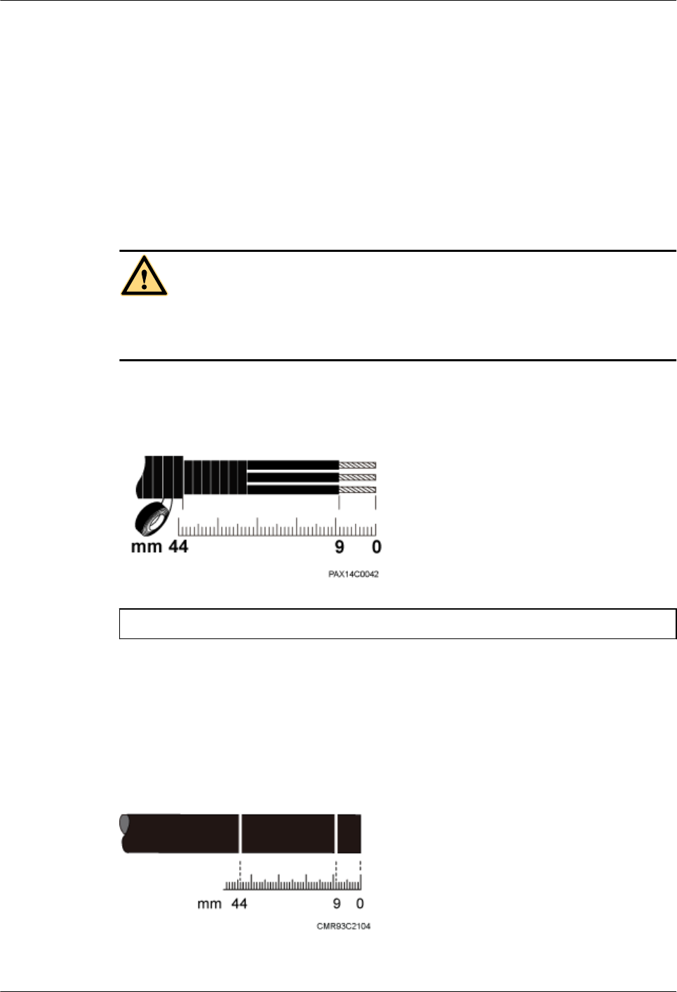
Figure 1-56 shows the scale for making a power cable for the RRU3931E.
Figure 1-56 RRU3931E power cable-making scale
(1) RRU3931E power cable-making scale
Procedure
Step 1 Unwind the required length of the power cable for different operations based on the scale. See
Figure 1-57
Figure 1-57 Determining the power cable length
Step 2 Remove the outer jacket of the power cable. See Figure 1-58
RRU3931E
Installation Guide 1 RRU3931E Installation Guide
Issue Draft A (2016-03-30) Huawei Proprietary and Confidential
Copyright © Huawei Technologies Co., Ltd.
53
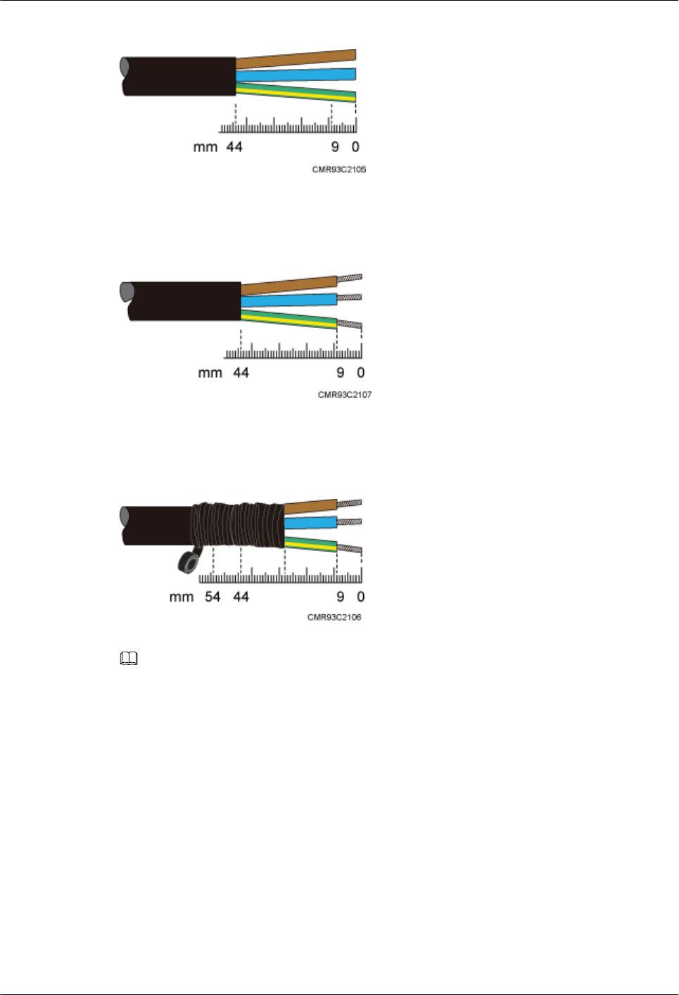
Figure 1-58 Removing the outer jacket of a cable
Step 3 Remove the outer jacket of each core wire. The length of the removed outer jacket must
match the tool-less female connector (pressfit type). See Figure 1-59.
Figure 1-59 Removing the outer jacket of core wires
Step 4 Use PVC insulation tapes to wrap the outer jackets of the three core wires and the adjacent
section of the AC power cable. See Figure 1-60.
Figure 1-60 Insulating a power cable
NOTE
It is good practice to wrap the three core wires for 16 mm and the adjacent section of the AC power
cable section for about 10 mm.
Step 5 Assemble a tool-less female connector (pressfit type) and the three core wires. See Figure
1-61.
RRU3931E
Installation Guide 1 RRU3931E Installation Guide
Issue Draft A (2016-03-30) Huawei Proprietary and Confidential
Copyright © Huawei Technologies Co., Ltd.
54
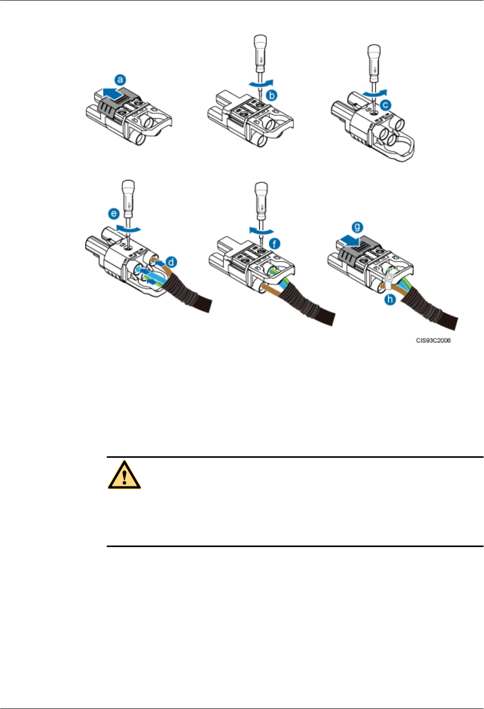
Figure 1-61 Adding a tool-less female connector (pressfit type) to core wires
1. Push the sliding block on the connector outwards along the arrow direction.
2. Use an M3 Phillips torque screwdriver to loosen the two screws.
3. Use the M3 Phillips torque screwdriver to loosen the screw on the other side.
4. Insert the brown core wire into the L port, the blue core wire into the N port, and the
yellowish green core wire to the PE port.
DANGER
Ensure that the positive and negative wires of all power cables are correctly connected.
Any incorrect power cable connection (such as reverse polarity connection) may cause
damage to equipment or unexpected personal injuries.
5. Use the M3 Phillips torque screwdriver to torque the screw to 0.5 N·m.
6. Use the M3 Phillips torque screwdriver to torque the two screws on the other side to 0.5
N·m.
7. Push the sliding block back in position along the arrow direction.
8. Use cable ties to bind the core wires to the connector.
Step 6 Gently pull each core wire to check that the connections are secure. The core wires can
remain fastened under external force of 30 N. Ensure that all copper wires are inserted into the
wiring terminal sockets and no copper wire is exposed outside the connector.
----End
RRU3931E
Installation Guide 1 RRU3931E Installation Guide
Issue Draft A (2016-03-30) Huawei Proprietary and Confidential
Copyright © Huawei Technologies Co., Ltd.
55
1.11.5 Small Cell Engineering Label
This section describes the content and presents the exterior of Small Cell engineering labels.
Label Content
The Small Cell engineering labels include the power label, ground label, alarm label, antenna
system label, optical transmission label, FE/GE electrical port label, and GPS label.
The labels are printed before delivery. Therefore, writing or printing is not required on site.
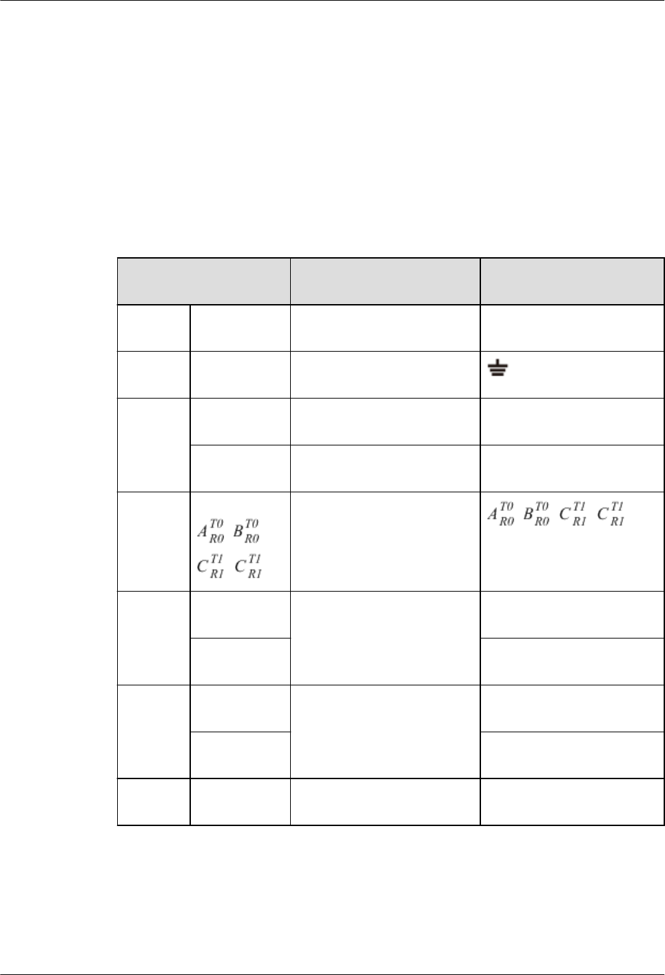
Table 1-8 describes the content of engineering labels.
Table 1-8 Small Cell Engineering Label Content
Label Content Description Corresponding port on
the base station
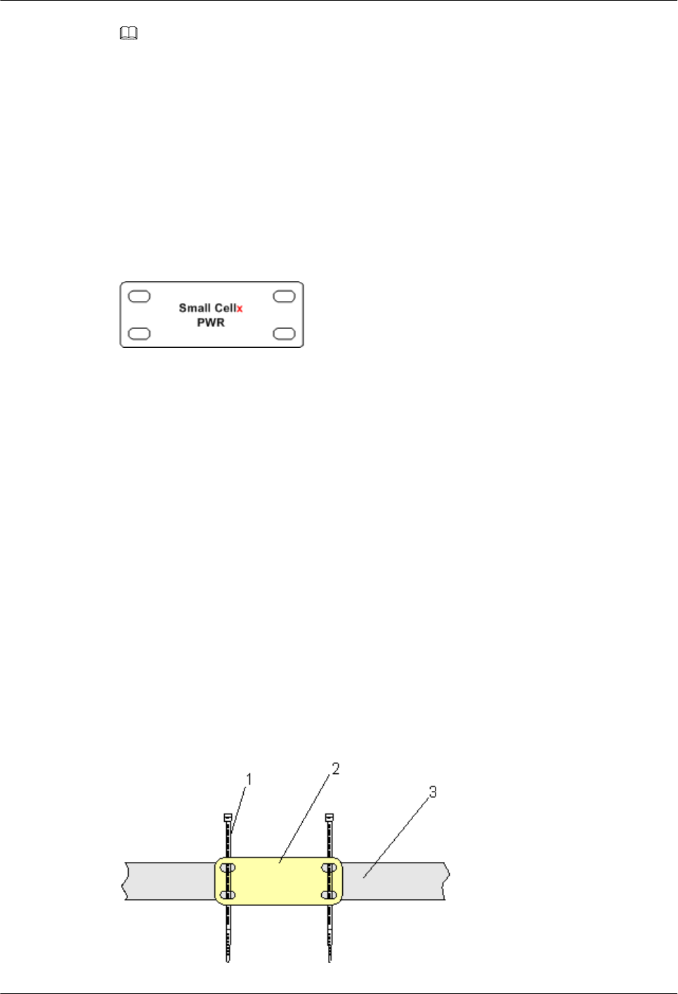
Power
label
Small Cellx
PWR
Label for the BTSx power
cable.
PWR
Ground
label
Small Cell
PGNDx
Label for the BTS ground
cable or equipotential cable.
Alarm
label
Small Cellx
EXT-ALM
Label for the BTSx alarm
cable.
EXT-ALM
Small Cellx
DBG
Label for the BTSx alarm
cable.
DBG
Antenna
system
label
Small Cellx
, ,
,
Label for the BTSx TX/RX
antenna port. , , ,
Optical
transmiss
ion label
Small Cellx
FE/GE2
Label for the BTSx fiber
optic cable.
FE/GE2
Small Cellx
FE/GE3
FE/GE3
FE/GE
electrical
port label
Small Cellx
FE/GE0
Label for the BTSx Ethernet
cable.
FE/GE0
Small Cellx
FE/GE1
FE/GE1
GPS
label
Small Cellx
GPS
Label for the BTSx GPS
cable.
GPS
RRU3931E
Installation Guide 1 RRU3931E Installation Guide
Issue Draft A (2016-03-30) Huawei Proprietary and Confidential
Copyright © Huawei Technologies Co., Ltd.
56
NOTE
lIn the label content, Small Cell identifies a Huawei micro base station.
lFor a single base station, only labels with Small Cell or Small Cell0 are used.
lFor two base stations at the same site: If UMTS and LTE base stations are located at the same site,
you are advised to label the UMTS base station as Small Cell0 and the LTE base station as Small
Cell1. If two base stations work in the same mode, label the one directly connected to external
devices as Small Cell0 and the cascaded one as Small Cell1.
Label Structure
Figure 1-62 shows the structure of a Small Cell engineering label.
Figure 1-62 Label structure
1.11.6 Attaching a Sign Plate Label
This section describes the procedures and precautions for attaching a sign plate label.
Context
lThis section applies to Huawei sign plate labels. If other engineering labels in
accordance with local standards are used on site, follow the local standards for attaching
sign plate labels.
lA sign plate label is usually used for a power cable, ground label, signal cable, and
antenna. This section uses 1.11.5 Small Cell Engineering Label as an example.
Procedure
Step 1 Lead the cable ties through the holes of a label, and then bind the label to the cable, as shown
in Figure 1-63. Ensure that the cable ties are led through the holes of the label in the same
direction.
Figure 1-63 Binding the label
RRU3931E
Installation Guide 1 RRU3931E Installation Guide
Issue Draft A (2016-03-30) Huawei Proprietary and Confidential
Copyright © Huawei Technologies Co., Ltd.
57
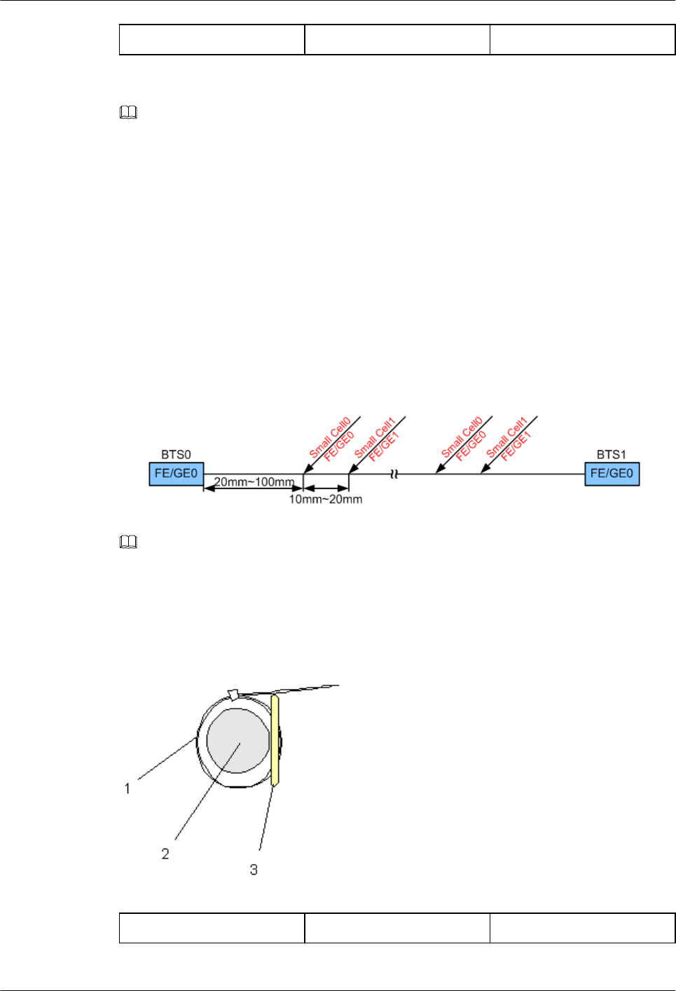
(1): Cable tie (2): Label (3): Cable
NOTE
You should use an outdoor cable tie with a appropriate width in outdoor scenarios (the default is black
cable tie with 3.6 mm or 0.14 in. width).
lThe position for banding the label is recommended from 20 mm to 100 mm (0.79 in. to
3.94 in.) away from the cable connector. Ensure the front of the label facing you and not
be covered.
lIn case of both ports of the cable connected have different silkscreen, both ends of the
cable should bind the port label on the two ends of cable. For example, in dual BTSs
cascading scenarios, one end of the cascading FE/GE cable is connected to LAN1 port
on BTS0, and the other end connected to WAN port on BTS1. At this point, both ends of
the cable should band two labels Micro BTS0 LAN1 and Micro BTS1 WAN. As shown
in Figure 1-64, the distance between the two labels is recommended from 10 mm to 20
mm (0.39 in. to 0.79 in.).
Figure 1-64 Positions for banding labels
NOTE
You may change the positions for attaching labels in actual situations. For example, you can bind a label
where the cable is bent.
Step 2 Tighten the cable tie, securing the label on the cable, and then cut off the extra part of the
cable tie, as shown in Figure 1-65.
Figure 1-65 Securing the label on the cable
(1): Cable tie (2): Cable (3): Label
RRU3931E
Installation Guide 1 RRU3931E Installation Guide
Issue Draft A (2016-03-30) Huawei Proprietary and Confidential
Copyright © Huawei Technologies Co., Ltd.
58
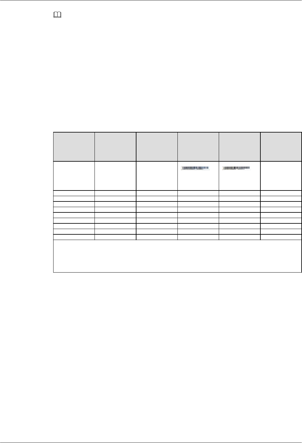
NOTE
lWhen you bind a label, ensure that the side with characters faces outwards.
lEnsure that the labels are attached in an orderly and neat manner. When you cut a cable tie, keep a
surplus length of 5 mm to 10 mm (0.20 in. to 0.39 in.).
----End
1.11.7 SN Collection Template
This section describes the SN collection template for RRU3931Es.
The SN collection template is used to record information of RRU3931Es at the initial
installation stage to facilitate subsequent commissioning and maintenance. Table 1-9
Table 1-9 SN collection template
No. Site
Number
Site Name Base
Station SN
ODM04A
SN
Location
Informatio
n
Sample xx RRU3931E xx floor, xx
building, xx
mansion
NOTE
The SN collection template defines the radio network to access and is essential to engineering and
subsequent maintenance, especially when multiple devices are installed at a short distance. Carefully
maintain this template.
RRU3931E
Installation Guide 1 RRU3931E Installation Guide
Issue Draft A (2016-03-30) Huawei Proprietary and Confidential
Copyright © Huawei Technologies Co., Ltd.
59