Huawei Technologies RRU3931E Remote Radio Unit User Manual Site Maintenance Guid
Huawei Technologies Co.,Ltd Remote Radio Unit Site Maintenance Guid
Contents
- 1. user manual regulatory compliance statement v2
- 2. user manual rru3931e installation guide
- 3. user manual rru3931e site maintenance guid
user manual rru3931e site maintenance guid

RRU3931E
V100R011C10
Site Maintenance Guid
Issue Draft A
Date 2016-03-30
HUAWEI TECHNOLOGIES CO., LTD.

Copyright © Huawei Technologies Co., Ltd. 2016. All rights reserved.
No part of this document may be reproduced or transmitted in any form or by any means without prior written
consent of Huawei Technologies Co., Ltd.
Trademarks and Permissions
and other Huawei trademarks are trademarks of Huawei Technologies Co., Ltd.
All other trademarks and trade names mentioned in this document are the property of their respective
holders.
Notice
The purchased products, services and features are stipulated by the contract made between Huawei and the
customer. All or part of the products, services and features described in this document may not be within the
purchase scope or the usage scope. Unless otherwise specified in the contract, all statements, information,
and recommendations in this document are provided "AS IS" without warranties, guarantees or
representations of any kind, either express or implied.
The information in this document is subject to change without notice. Every effort has been made in the
preparation of this document to ensure accuracy of the contents, but all statements, information, and
recommendations in this document do not constitute a warranty of any kind, express or implied.
Huawei Technologies Co., Ltd.
Address: Huawei Industrial Base
Bantian, Longgang
Shenzhen 518129
People's Republic of China
Website: http://www.huawei.com
Email: support@huawei.com
Issue Draft A (2016-03-30) Huawei Proprietary and Confidential
Copyright © Huawei Technologies Co., Ltd.
i

Contents
1 RRU3931E Site Maintenance Guide.......................................................................................... 1
1.1 Changes in RRU3931E Site Maintenance Guide........................................................................................................... 3
1.2 Turning On or Off Indicators..........................................................................................................................................3
1.2.1 Turning On Indicators..................................................................................................................................................3
1.2.2 Turning Off Indicators................................................................................................................................................. 3
1.3 Powering On or Off a RRU3931E..................................................................................................................................3
1.3.1 Powering On a RRU3931E..........................................................................................................................................3
1.3.2 Powering Off a RRU3931E.........................................................................................................................................5
1.4 Replacing a RRU3931E..................................................................................................................................................5
1.5 Replacing an Optical Module......................................................................................................................................... 8
RRU3931E
Site Maintenance Guid Contents
Issue Draft A (2016-03-30) Huawei Proprietary and Confidential
Copyright © Huawei Technologies Co., Ltd.
ii

1 RRU3931E Site Maintenance Guide
Introduction
This document describes routine maintenance items for a RRU3931E, such as power-on and
power-off operations. It also explains how to replace the components and modules.
Product Version
The following table lists the product versions related to this document.
Product Name Solution Version Product Version
RRU3931E lSRAN11.1 and later
versions
lRAN18.1 and later
versions
leRAN11.1 and later
versions
V100R011C10 and later versions
Intended Audience
This document is intended for:
lSystem engineers
lSite maintenance engineers
Organization
1.1 Changes in RRU3931E Site Maintenance Guide1.1 Changes in RRU3931E Site
Maintenance Guide
This section describes the changes in RRU3931E Site Maintenance Guide.
1.2 Turning On or Off Indicators1.2 Turning On or Off Indicators
Indicators on the RRU3931E can be turned on or off.
RRU3931E
Site Maintenance Guid 1 RRU3931E Site Maintenance Guide
Issue Draft A (2016-03-30) Huawei Proprietary and Confidential
Copyright © Huawei Technologies Co., Ltd.
1

1.3 Powering On or Off a RRU3931E1.3 Powering On or Off a RRU3931E
The indicator status of a RRU3931E must be observed following a power-on to determine its
running status. Normal power-off can be used to power off a RRU3931E.
1.4 Replacing a RRU3931E1.4 Replacing a RRU3931E
RRU3931Es employ modular design and faulty ones must be replaced promptly. Replacing a
RRU3931E interrupts all ongoing services carried by it.
1.5 Replacing an Optical Module1.5 Replacing an Optical Module
An optical module implements photoelectric conversion, enabling optical transmission
between a RRU3931E and other devices. Before replacing an optical module, disconnect the
fiber optic cable from the optical module. The disconnection interrupts transmission of optical
signals.
1.1 Changes in RRU3931E Site Maintenance Guide
This section describes changes in RRU3931E Site Maintenance Guide.
1.2 Turning On or Off Indicators
Indicators on the RRU3931E can be turned on or off.
1.3 Powering On or Off a RRU3931E
The indicator status of a RRU3931E must be observed following a power-on to determine its
running status. Normal power-off can be used to power off a RRU3931E.
1.4 Replacing a RRU3931E
RRU3931Es employ modular design and faulty ones must be replaced promptly. Replacing a
RRU3931E interrupts all ongoing services carried by it.
1.5 Replacing an Optical Module
An optical module implements photoelectric conversion, enabling optical transmission
between a RRU3931E and other devices. Before replacing an optical module, disconnect the
fiber optic cable from the optical module. The disconnection interrupts transmission of optical
signals.
RRU3931E
Site Maintenance Guid 1 RRU3931E Site Maintenance Guide
Issue Draft A (2016-03-30) Huawei Proprietary and Confidential
Copyright © Huawei Technologies Co., Ltd.
2

1.1 Changes in RRU3931E Site Maintenance Guide
This section describes changes in RRU3931E Site Maintenance Guide.
Draft A (2016-03-30)
This is a draft.
1.2 Turning On or Off Indicators
Indicators on the RRU3931E can be turned on or off.
1.2.1 Turning On Indicators
Indicators on a RRU3931E may need to be turned on before routine maintenance is
performed.
Procedure
Instruct the network operator to run the SET INDICATORSW command on the RRU3931E
to turn on the indicators.
Configuration example: SET INDICATORSW: INDICATORSWITCH=ON;
The installation or maintenance personnel can locally observe the indicator status.
1.2.2 Turning Off Indicators
After installation or maintenance is completed, indicators on a RRU3931E can be turned off
as required.
Procedure
Instruct the network operator to run the SET INDICATORSW command on the RRU3931E
to turn off the indicators.
Configuration example: SET INDICATORSW: INDICATORSWITCH=OFF;
The installation or maintenance personnel can locally observe that all the indicators except the
WIFI indicator are off.
1.3 Powering On or Off a RRU3931E
The indicator status of a RRU3931E must be observed following a power-on to determine its
running status. Normal power-off can be used to power off a RRU3931E.
1.3.1 Powering On a RRU3931E
This section describes how to power on a RRU3931E and determine its running status by its
indicator status.
RRU3931E
Site Maintenance Guid 1 RRU3931E Site Maintenance Guide
Issue Draft A (2016-03-30) Huawei Proprietary and Confidential
Copyright © Huawei Technologies Co., Ltd.
3
Prerequisites
lThe RRU3931E and its cables have been installed.
lThe input voltage of the RRU3931E ranges from 110 V AC to 220 V AC, and the
frequency ranges from 50 Hz to 60 Hz.
Context
NOTICE
After a RRU3931E is unpacked, power it on within 24 hours. If the RRU3931E is powered
off for maintenance, restore power to it within 24 hours.
Procedure
Step 1 Power on the RRU3931E.
DANGER
Do not look into optical modules without eye protection after the RRU3931E is powered on.
Step 2 Wait for 3 to 5 minutes, and observe the indicator status. Then, take actions based on the
indicator status.
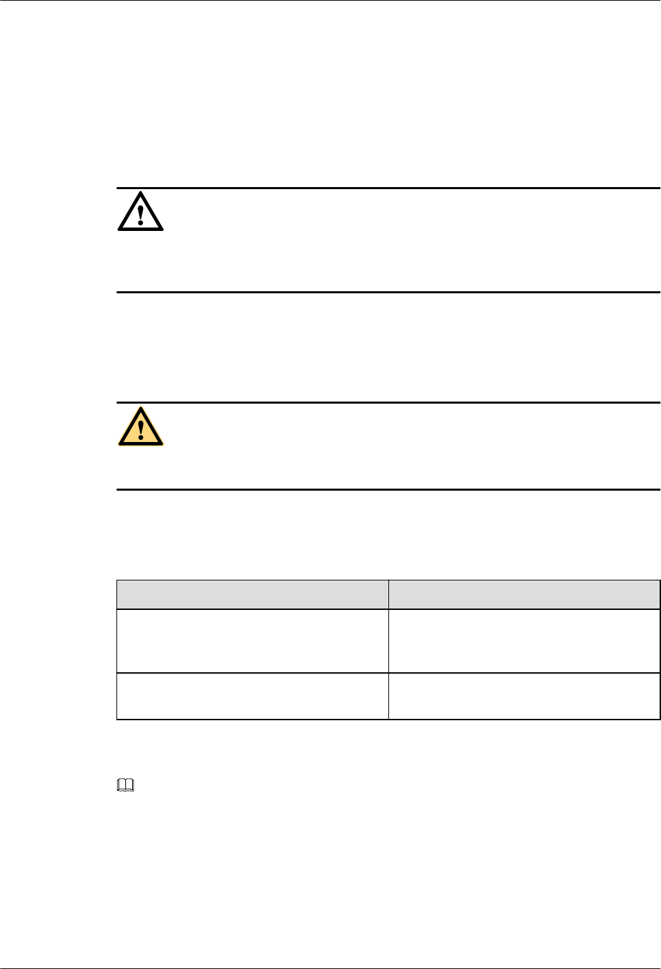
Table 1-1 RRU3931E indicator status
If... Then...
The RUN indicator blinks (on for 1s and off
for 1s), the ALM indicator is off, and the
RRU3931E is running correctly
End the power-on check task.
Any other indicator status is observed The RRU3931E is faulty. Rectify the faults,
and go to Step 1
NOTE
lCheck the status of indicators on all cascaded RRU3931Es in cascading networking.
lA RRU3931E takes about 3 minutes to complete the startup procedure, during which the
indicator status is negligible.
lDuring a startup, a RRU3931E reads and writes the flash memory and therefore the
indicators blinking quickly may blink irregularly for 1s to 2s, which does not affect
services.
----End
RRU3931E
Site Maintenance Guid 1 RRU3931E Site Maintenance Guide
Issue Draft A (2016-03-30) Huawei Proprietary and Confidential
Copyright © Huawei Technologies Co., Ltd.
4

1.3.2 Powering Off a RRU3931E
This section describes how to power off a RRU3931E.
Procedure
Step 1 Switch off the external power supply equipment for the RRU3931E.
----End
1.4 Replacing a RRU3931E
RRU3931Es employ modular design and faulty ones must be replaced promptly. Replacing a
RRU3931E interrupts all ongoing services carried by it.
Prerequisites
lTools and materials, such as electrostatic discharge (ESD) gloves, torque wrench, and
M10 hex key screwdriver, are ready.
lThe RRU3931E to be replaced has been confirmed, and a new RRU3931E has been
prepared.
lYou have obtained site visit permission.
Procedure
Step 1 Ask the network operator to perform the following preparations for a RRU3931E
replacement:
1. Block all the cells served by the RRU3931E to be replaced.
–Run the BLK CELL command if the RRU3931E works in LTE mode.
–Run the BLK ULOCELL command if the RRU3931E works in UMTS mode.
2. Change the SN to that of the new RRU3931E.
3. Upload a configuration file for the new RRU3931E over FTP. For details, see
RRU3931E Commissioning Guide.
4. Copy the configuration file and required software package to a TF card or a laptop where
the LMT has been installed.
NOTICE
Do not touch the RRU3931E that is just powered off until it cools down.
Step 2 Switch off the external power supply equipment for the RRU3931E to be replaced.
NOTICE
Take proper ESD protection measures, for example, wear ESD gloves, to prevent electrostatic
damage to the RRU3931E or its electronic components.
RRU3931E
Site Maintenance Guid 1 RRU3931E Site Maintenance Guide
Issue Draft A (2016-03-30) Huawei Proprietary and Confidential
Copyright © Huawei Technologies Co., Ltd.
5
Step 3 Put on ESD gloves.
Step 4 Record the horizontal angle and vertical angle of the RRU3931E. Pay attention to the
direction.
Step 5 Record cable connection positions on the bottom and side maintenance cavities of the
RRU3931E.
Step 6 Remove the cables on the RRU3931E bottom and side maintenance cavities from external
devices.
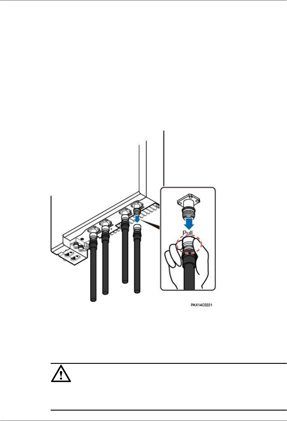
When removing an RF jumper, hold tightly the metal part (in the red dotted circle in Figure
1-1) of the Smart-type N male connector and pull it down with proper force. See Figure 1-1.
Figure 1-1 Removing an RF jumper
Step 7 Use an M10 hex key screwdriver to remove the angle adjusting screw on the top of the
RRU3931E attachment plate. Push the RRU3931E and its attachment plate upward out of the
angle adjusting mounting bracket. See Figure 1-2.
NOTICE
When demounting a RRU3931E, hold the handles tight and gently lift the RRU3931E to
prevent it from falling.
RRU3931E
Site Maintenance Guid 1 RRU3931E Site Maintenance Guide
Issue Draft A (2016-03-30) Huawei Proprietary and Confidential
Copyright © Huawei Technologies Co., Ltd.
6
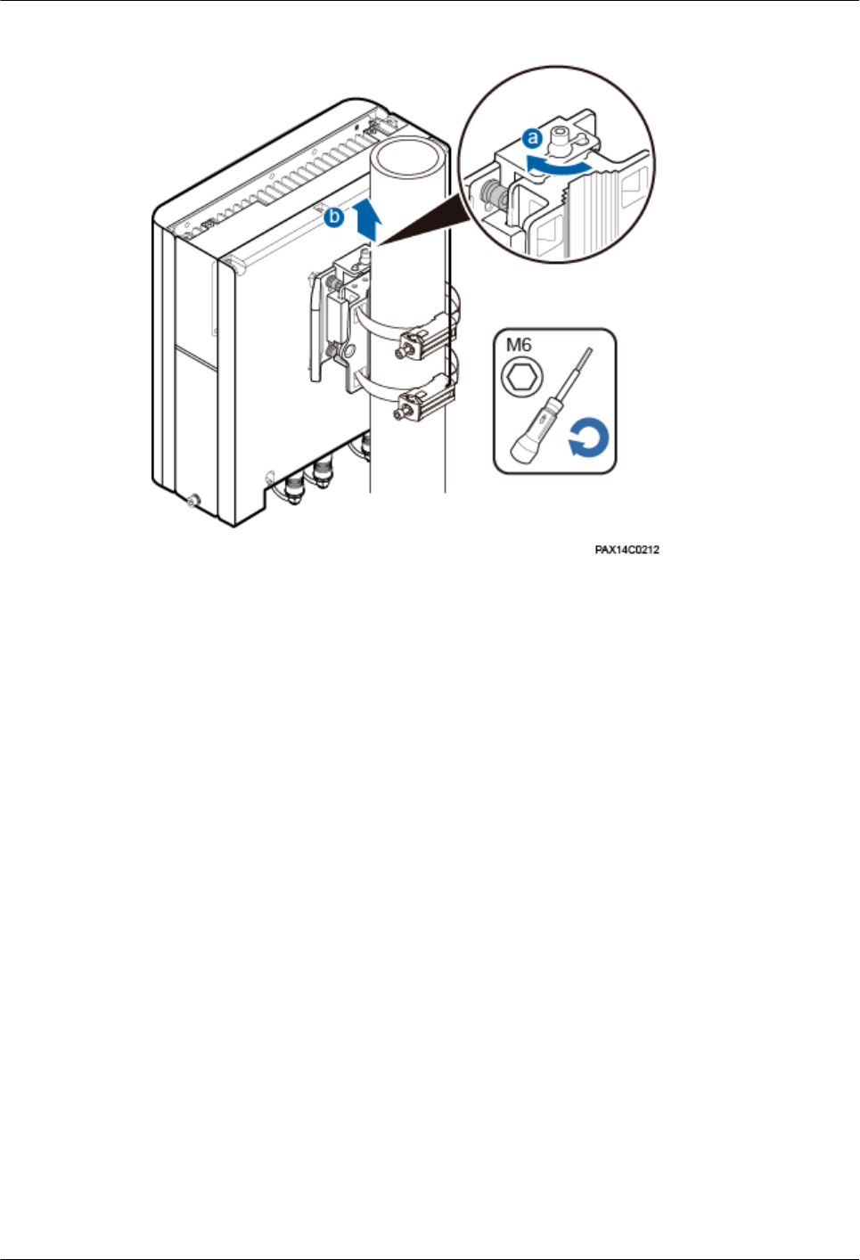
Figure 1-2 Demounting a RRU3931E
Step 8 Install a new RRU3931E and adjust the horizontal and vertical angles to be the same as those
recorded in Step 3. Use the M10 hex key screwdriver to torque the angle adjusting screw on
the top to 28 N·m.
Step 9 Connect all the cables on the new RRU3931E and seal the vacant ports with waterproof
rubber plugs.
Step 10 Power on the new RRU3931E by following instructions provided in 1.3.1 Powering On a
RRU3931E"1.3.1 Powering On a RRU3931E."
Step 11 Check the operating status of the new RRU3931E by its indicator status. For the meanings of
the indicator status, see section "Ports and Indicators" in RRU3931E Hardware Description.
Step 12 Download the configuration file and software package to the new RRU3931E using either of
the following methods:
lUsing the LMT
–On the Upgrade Software tab page, select Download Configuration File and
Download Version Software to download the configuration file and software
package. Select Activate Configuration File and Activate Version Software to
activate the configuration file and software package. After the activation is
completed, the RRU3931E automatically restarts and runs the new software. For
details, see LMT User Guide.
–Check that no alarm is generated on the new RRU3931E. For details, see LMT User
Guide.
lUsing a TF card. For details, see RRU3931E Commissioning Guide.
Step 13 Request the network operator to perform the following operations:
1. Unblock all cells served by the RRU3931E.
RRU3931E
Site Maintenance Guid 1 RRU3931E Site Maintenance Guide
Issue Draft A (2016-03-30) Huawei Proprietary and Confidential
Copyright © Huawei Technologies Co., Ltd.
7

–Run the UBL CELL command if the RRU3931E works in LTE mode.
–Run the UBL ULOCELL command if the RRU3931E works in UMTS mode.
2. Manually synchronize inventory data.
3. Manually change the RRU3931E status from TESTING to NORMAL.
Step 14 Take off the ESD gloves and pack up all the tools.
----End
Follow-up Procedure
lPlace the replaced RRU3931E into an ESD bag. Then, place the ESD bag into a foam-
padded carton or the packing box of the new RRU3931E.
lFill in the fault form with the detail information of the replaced RRU3931E.
lContact the local Huawei office to handle the faulty RRU3931E.
1.5 Replacing an Optical Module
An optical module implements photoelectric conversion, enabling optical transmission
between a RRU3931E and other devices. Before replacing an optical module, disconnect the
fiber optic cable from the optical module. The disconnection interrupts transmission of optical
signals.
Prerequisites
lThe type and number of optical modules to be replaced are confirmed, and new optical
modules are ready.
lTools and materials, such as ESD gloves, M10 Phillips screwdrivers, ESD box or ESD
bag, are ready.
Context
lOptical modules are inserted in FE/GE2 and FE/GE3 ports of the RRU3931E.
lOptical modules are hot-swappable.
lOptical module replacement involves disconnecting the fiber optic cable, removing the
faulty optical module, inserting a new optical module, connecting the fiber optic cable to
the new module, and waiting for the link on the Ethernet optical port to resume. The
whole process takes about 5 minutes.
Procedure
Step 1 Put on ESD gloves.
NOTICE
Take proper ESD protection measures, for example, wear ESD gloves, to prevent electrostatic
damage to the boards, modules, or electronic components.
RRU3931E
Site Maintenance Guid 1 RRU3931E Site Maintenance Guide
Issue Draft A (2016-03-30) Huawei Proprietary and Confidential
Copyright © Huawei Technologies Co., Ltd.
8
Step 2 Switch off the external power supply equipment for the RRU3931E.
Step 3 Opening the maintenance cavity covers. If the maintenance cavity covers cannot be opened
because the RRU3931E is installed on a wall with large-angle adjustment, perform the
following operations:
1. Record the adjusted angle for the RRU3931E.
2. Adjust the horizontal angle of the RRU3931E.
3. Open the maintenance cavity covers.
Step 4 Record the connection positions of the faulty optical module and fiber optic cable.
Step 5 Press the bulge on the optical connector and remove the connector from the faulty optical
module.
NOTICE
Do not look into the disconnected fiber optic cable or optical module without eye protection.
Step 6 Lower the puller on the faulty optical module, and then pull the puller until the optical module
is removed from the RRU3931E.
Step 7 According to the label on the faulty optical module, prepare a new one of the same type.
Install the new optical module into the FE/GE optical port on the RRU3931E.
NOTE
The new optical module must match the rate at the optical FE/GE port.
Step 8 Insert the optical connector into the optical module, and closing the maintenance cavity
covers.
Step 9 Power on the new RRU3931E by following instructions provided in 1.3.1 Powering On a
RRU3931E"1.3.1 Powering On a RRU3931E."
Step 10 Check the transmission of FE/GE signals by the indicator status. For the meanings of the
indicator status, see section "Ports and Indicators" in RRU3931E Hardware Description.
Step 11 Take off the ESD gloves and pack up all the tools.
----End
Follow-up Procedure
lPlace the replaced optical module into the ESD box or bag. Then, place the ESD box or
bag into a foam-padded carton or the packing box of the new optical module.
lFill in the fault form with the detail information of the replaced optical module.
lContact the local Huawei office to handle the faulty optical module.
RRU3931E
Site Maintenance Guid 1 RRU3931E Site Maintenance Guide
Issue Draft A (2016-03-30) Huawei Proprietary and Confidential
Copyright © Huawei Technologies Co., Ltd.
9