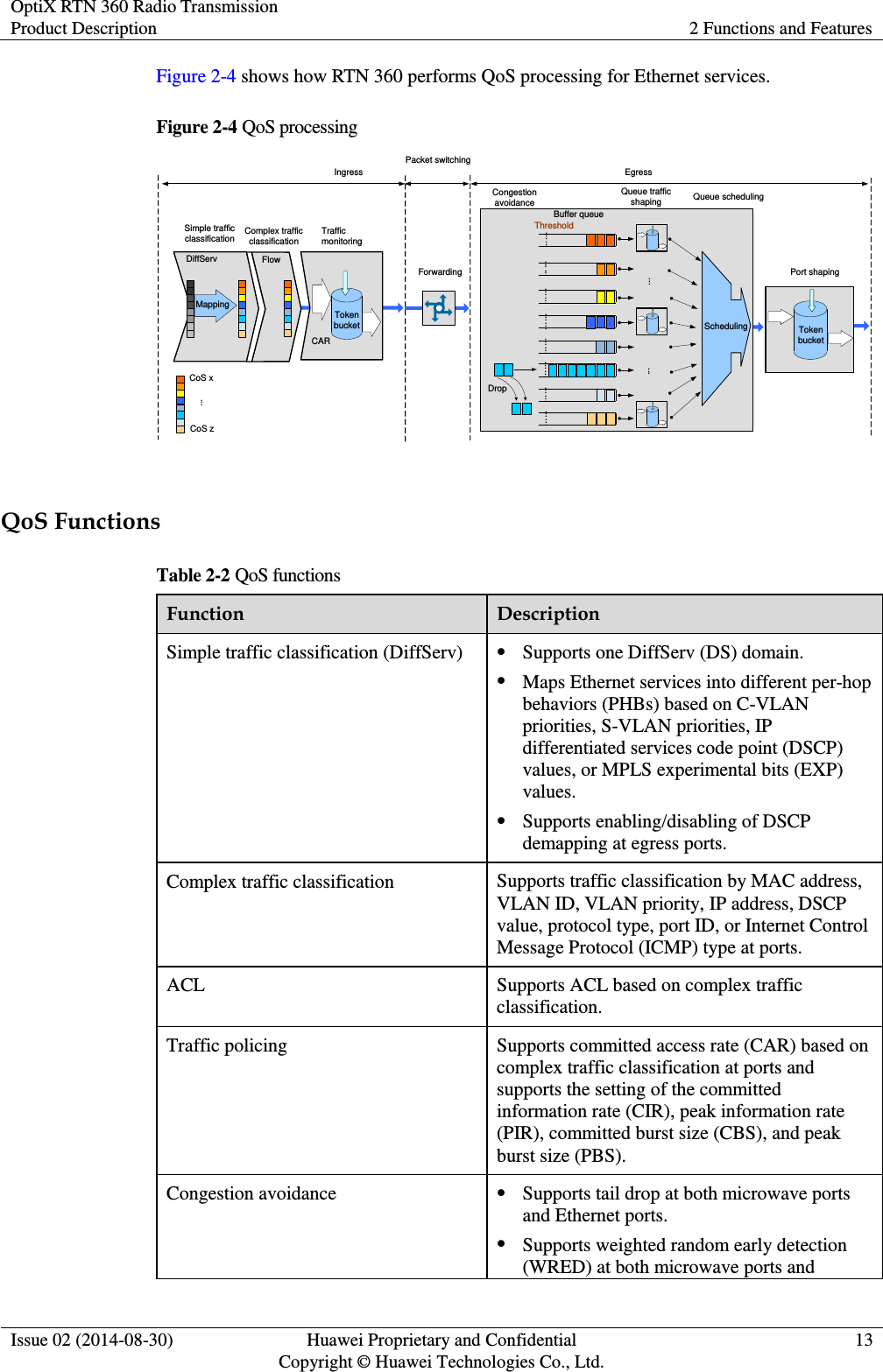
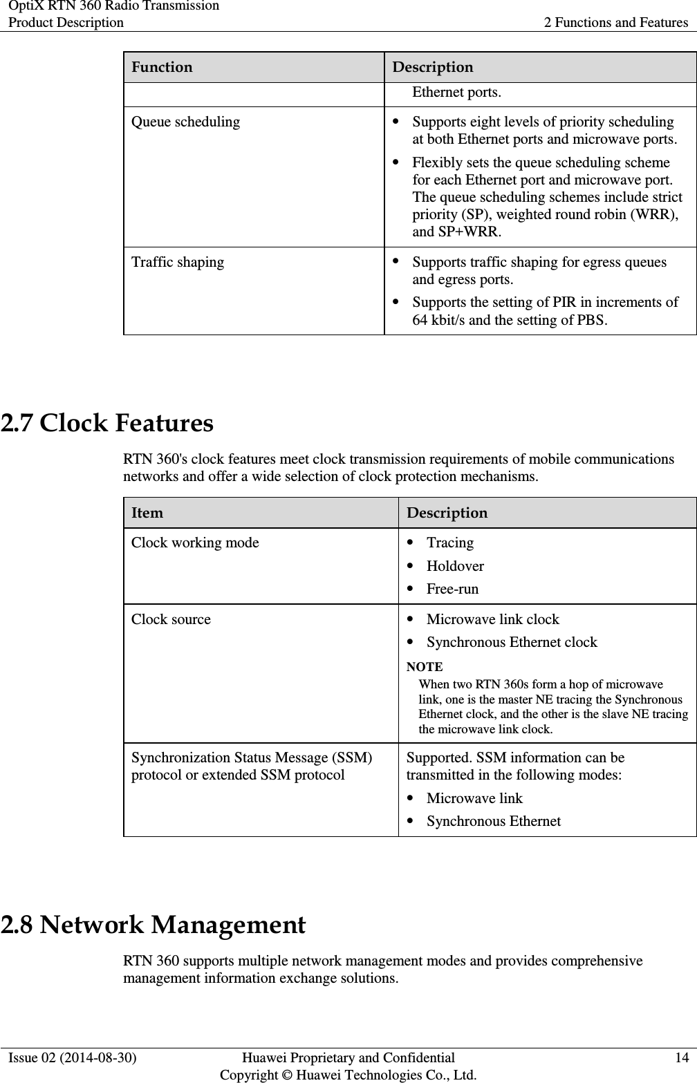
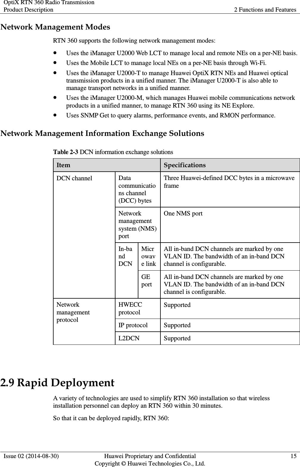
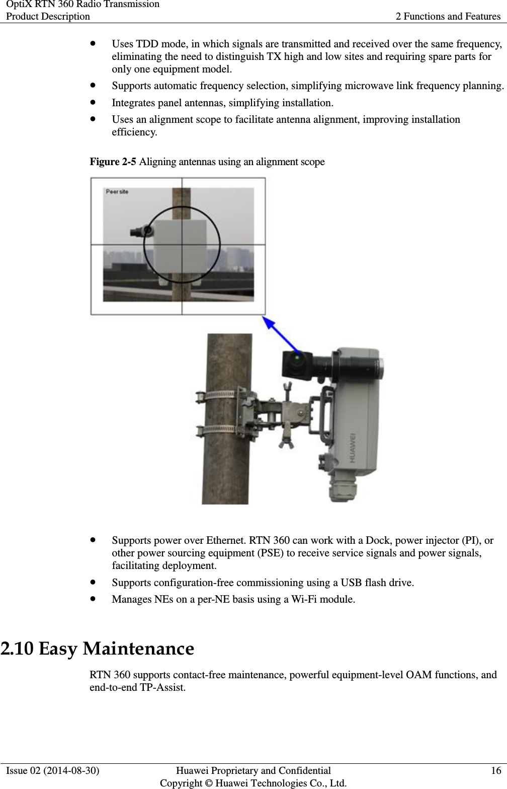
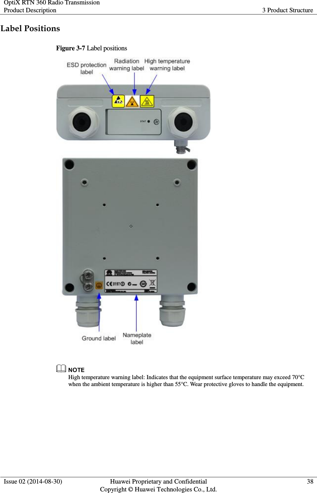
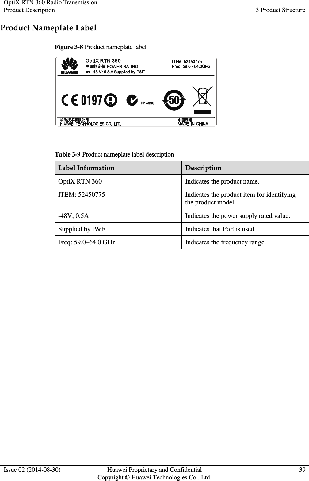
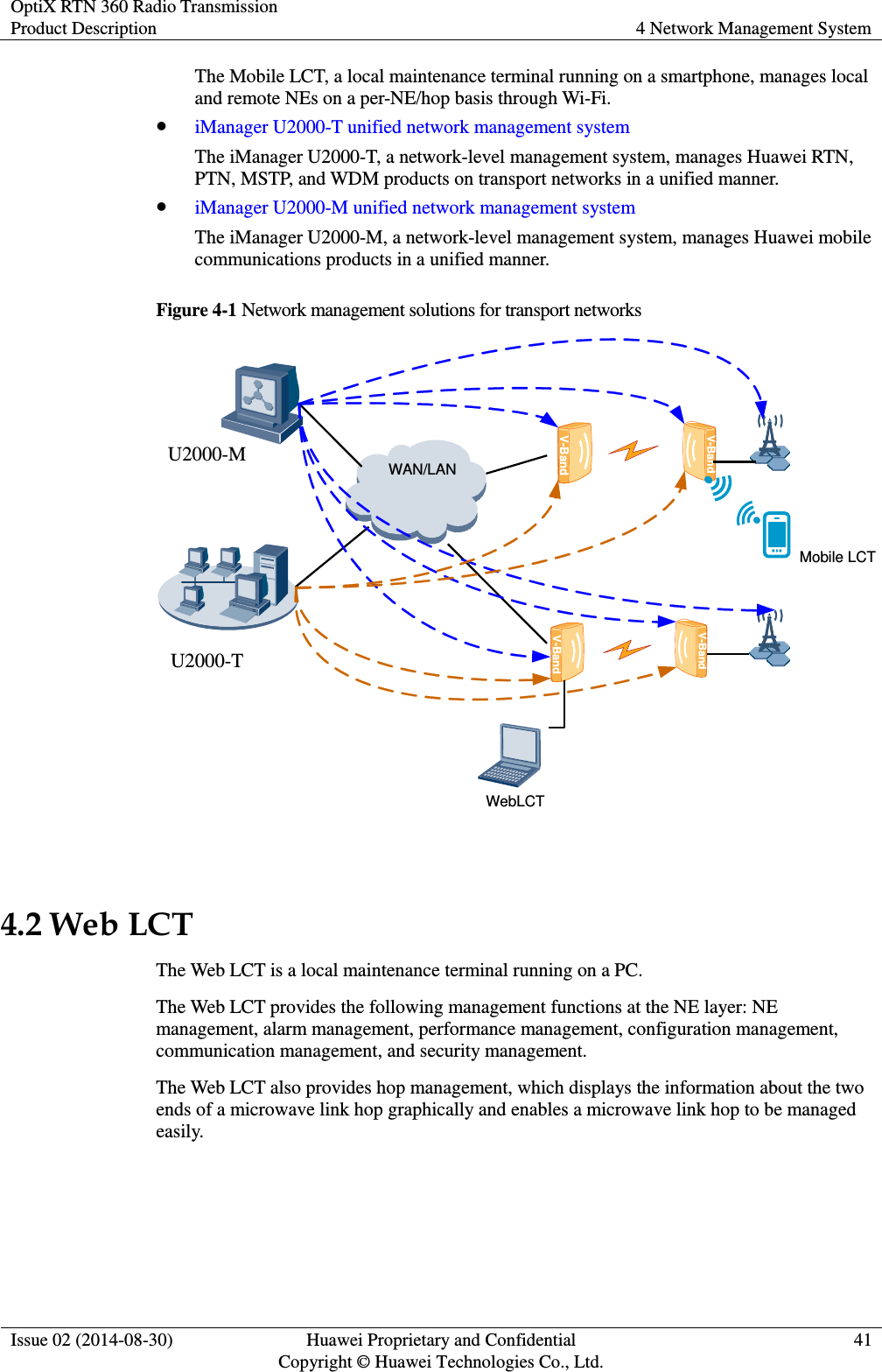
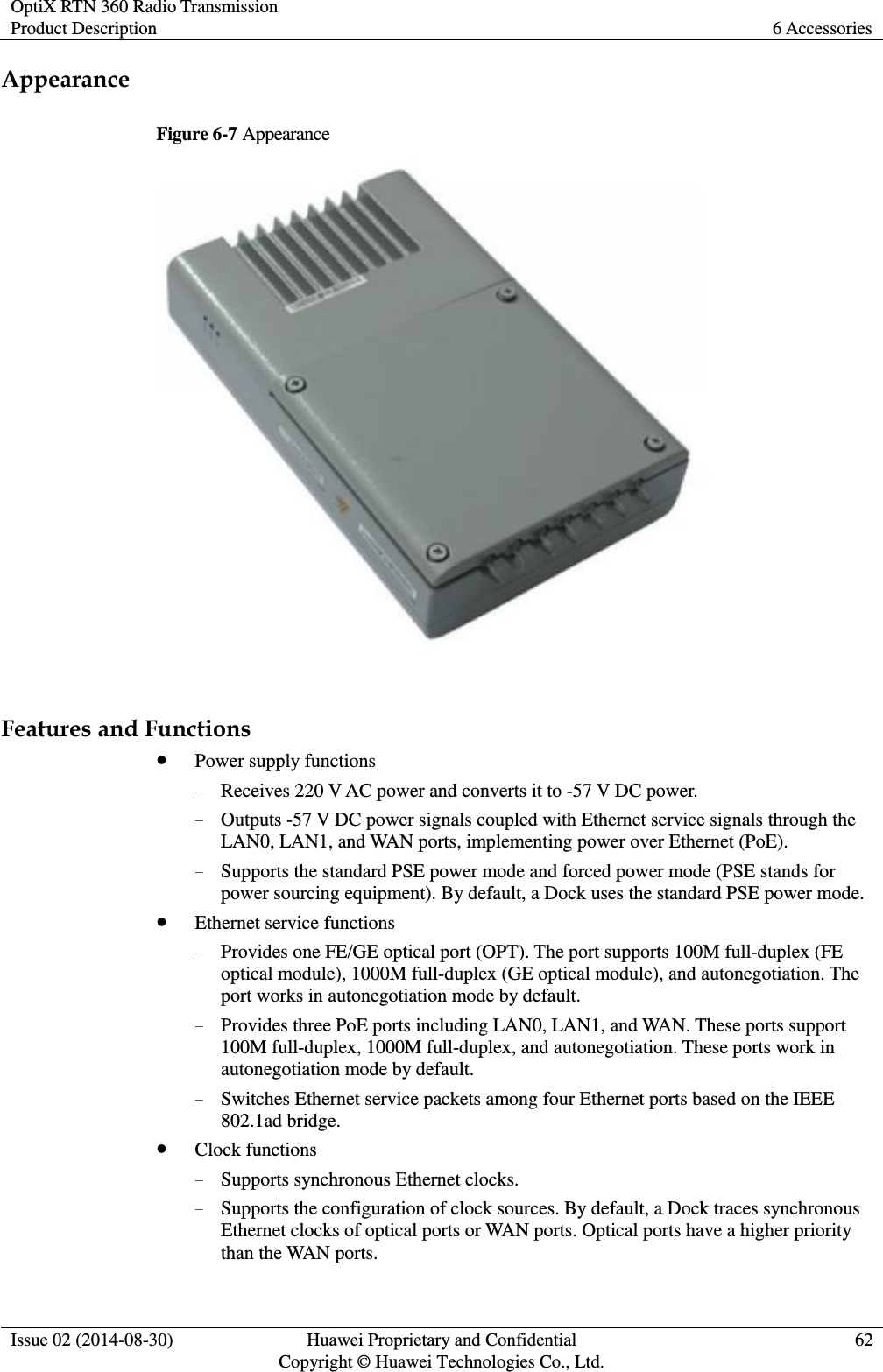
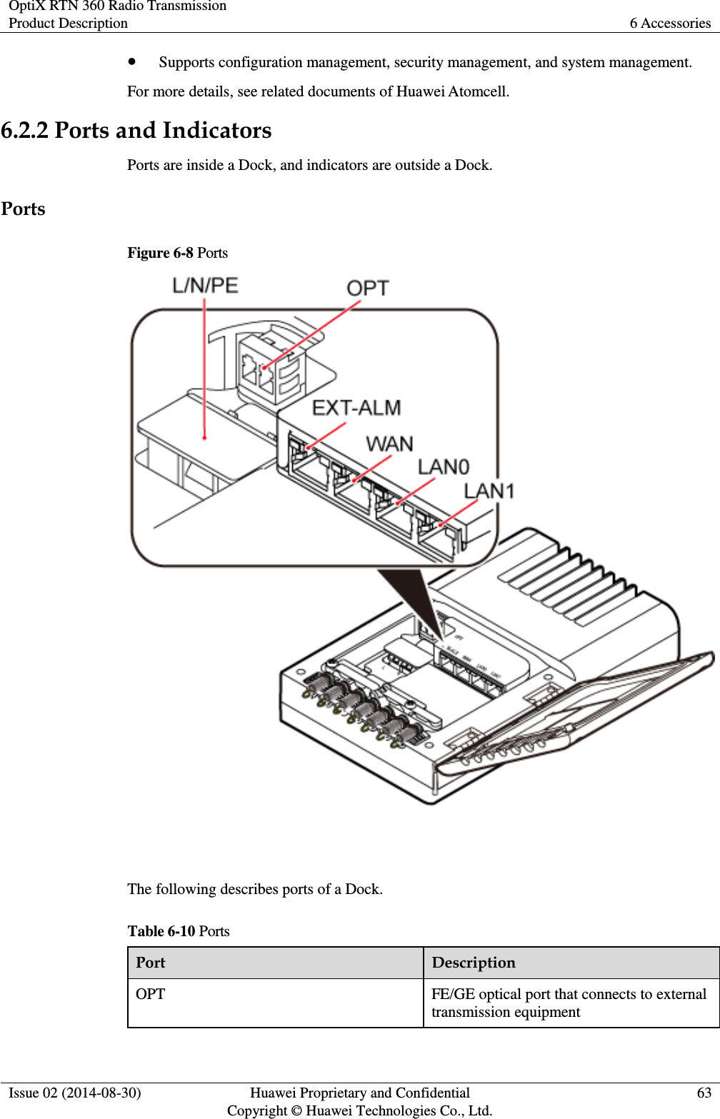
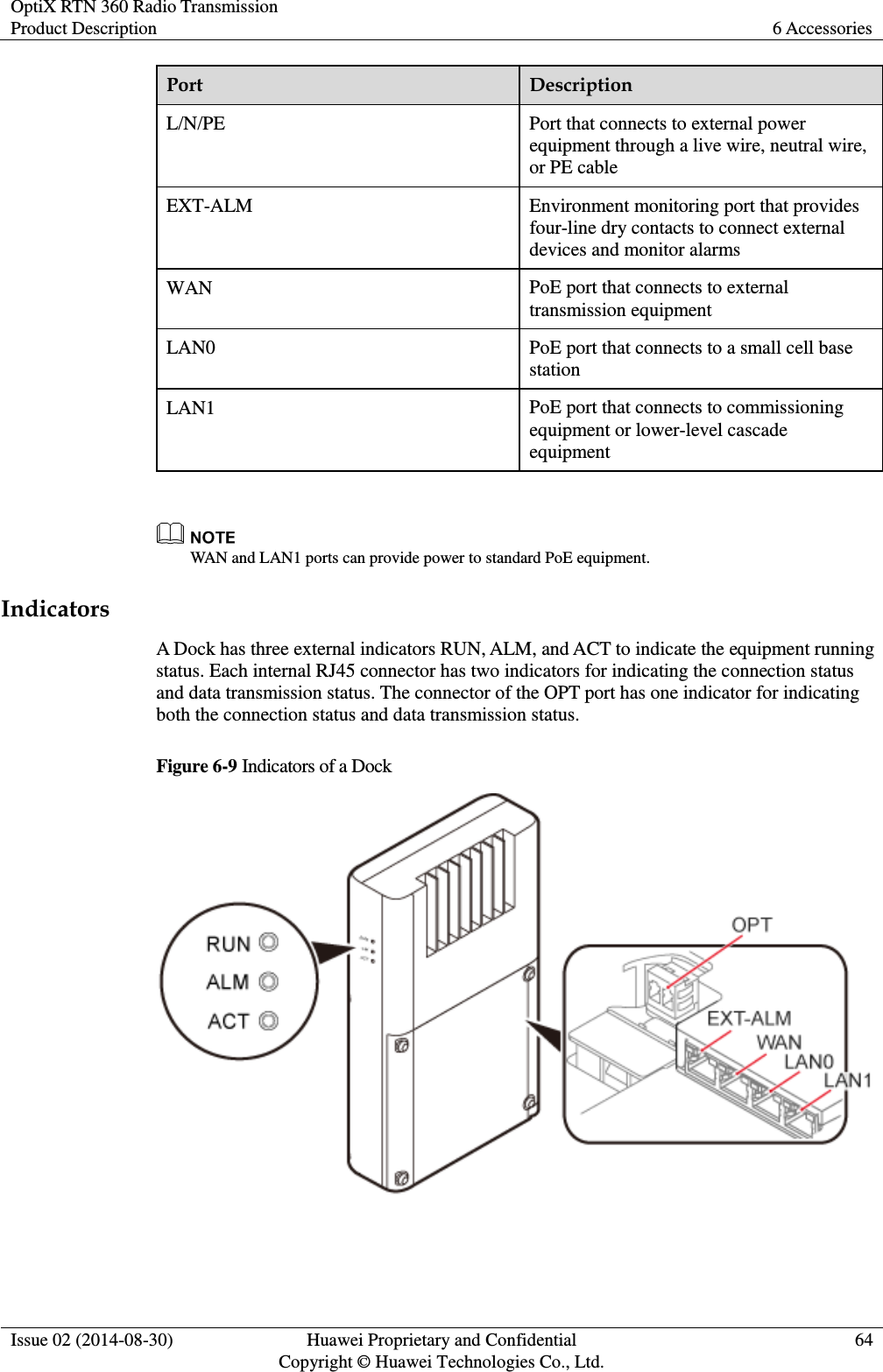
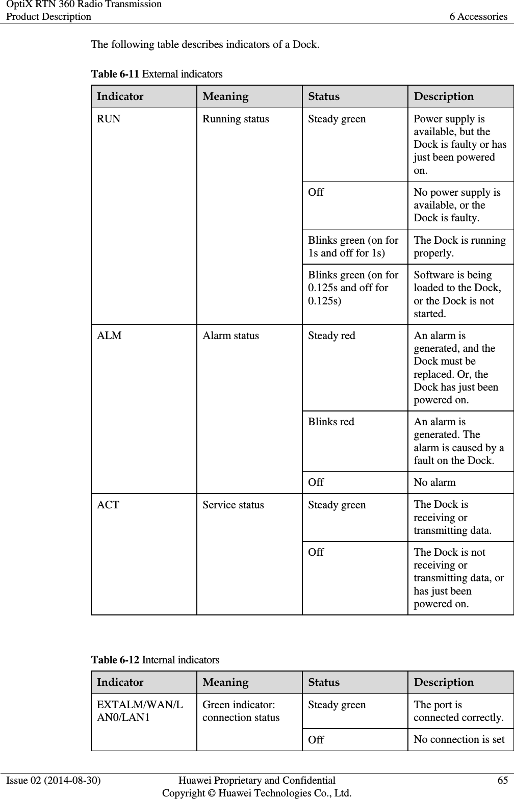
Huawei Technologies RTN360 Radio Transmission System User Manual Product Description

Huawei Technologies Co.,Ltd Radio Transmission System Product Description

Users Manual

        OptiX RTN 360 Radio Transmission V100R001C00 Product Description   Issue 02 Date 2014-08-30 HUAWEI TECHNOLOGIES CO., LTD.
 Issue 02 (2014-08-30) Huawei Proprietary and Confidential                                     Copyright © Huawei Technologies Co., Ltd. i    Copyright © Huawei Technologies Co., Ltd. 2014. All rights reserved. No part of this  document  may be reproduced or transmitted in any form or by any means without prior written consent of Huawei Technologies Co., Ltd.  Trademarks and Permissions   and other Huawei trademarks are trademarks of Huawei Technologies Co., Ltd. All  other  trademarks  and  trade  names  mentioned  in  this  document  are  the  property  of  their  respective holders.  Notice The purchased products, services and features are stipulated by the contract made between Huawei and the customer.  All or part of the products, services and features described in this document may not be within the purchase scope or the usage scope. Unless otherwise specified in the contract, all statements, information, and recommendations in this document are provided "AS IS" without warranties, guarantees or representations of any kind, either express or implied. The information in this document is subject to change without notice. Every effort has been made in the preparation  of  this  document  to  ensure  accuracy  of  the  contents,  but  all  statements,  information,  and recommendations in this document do not constitute a warranty of any kind, express or implied.     Huawei Technologies Co., Ltd. Address: Huawei Industrial Base Bantian, Longgang Shenzhen 518129 People's Republic of China Website: http://www.huawei.com Email: support@huawei.com
OptiX RTN 360 Radio Transmission Product Description About This Document  Issue 02 (2014-08-30) Huawei Proprietary and Confidential                                     Copyright © Huawei Technologies Co., Ltd. ii  About This Document Related Versions The following table lists the product versions related to this document. Product Name Version OptiX RTN 360 V100R001C00 iManager U2000–T V200R014C50 iManager U2000–M V200R014C00  Intended Audience This document is intended for:  Network planning engineer    Hardware installation engineer    Installation and commissioning engineer    Field maintenance engineer    Data configuration engineer    System maintenance engineer   Familiarity with the basic knowledge related to digital microwave communication technology will help you apply the information in this document.   Symbol Conventions The symbols that may be found in this document are defined as follows. Symbol Description   Indicates an imminently hazardous situation which, if not avoided, will result in death or serious injury.
OptiX RTN 360 Radio Transmission Product Description About This Document  Issue 02 (2014-08-30) Huawei Proprietary and Confidential                                     Copyright © Huawei Technologies Co., Ltd. iii  Symbol Description   Indicates a potentially hazardous situation which, if not avoided, could result in death or serious injury.  Indicates a potentially hazardous situation which, if not avoided, may result in minor or moderate injury.  Indicates a potentially hazardous situation which, if not avoided, could result in equipment damage, data loss, performance deterioration, or unanticipated results. NOTICE is used to address practices not related to personal injury.   Calls attention to important information, best practices and tips. NOTE is used to address information not related to personal injury, equipment damage, and environment deterioration.  General Conventions The general conventions that may be found in this document are defined as follows. Convention Description Times New Roman Normal paragraphs are in Times New Roman. Boldface Names of files, directories, folders, and users are in boldface. For example, log in as user root. Italic Book titles are in italics. Courier New Examples of information displayed on the screen are in Courier New.  Change History Changes between document issues are cumulative. The latest document issue contains all the changes made in earlier issues. Updates in Issue 02 (2014-08-30) Based on Product Version V100R001C00 This issue is the second release for the product version V100R001C00.
OptiX RTN 360 Radio Transmission Product Description About This Document  Issue 02 (2014-08-30) Huawei Proprietary and Confidential                                     Copyright © Huawei Technologies Co., Ltd. iv  Updates are as follows. Update Description 1.2 Product Specifications Optimized the table containing product specifications. 3.4 Indicators Added an explanation for the link status of the STAT indicator. 5.1 Ethernet Service Specifications Optimized the table containing Ethernet service throughput specifications. A.2 Component Photos Added section "Component Photos." A.3 Compliance Standards Added section "Compliance Standards." Entire document Fixed known defects.  Issue 01 (2014-04-30) This issue is the first release for the product version V100R001C00.
OptiX RTN 360 Radio Transmission Product Description Contents  Issue 02 (2014-08-30) Huawei Proprietary and Confidential                                     Copyright © Huawei Technologies Co., Ltd. v  Contents About This Document .................................................................................................................... ii 1 Product Introduction .................................................................................................................... 1 1.1 Network Application ........................................................................................................................................ 1 1.2 Product Specifications ...................................................................................................................................... 2 1.3 Site Configurations ........................................................................................................................................... 3 1.3.1 Sites Providing One-Direction Microwave Links ................................................................................... 3 1.3.2 Sites Providing Two-Direction Microwave Links ................................................................................... 4 1.3.3 Sites Providing Multi-direction Microwave Links .................................................................................. 5 2 Functions and Features ................................................................................................................ 7 2.1 Integration ........................................................................................................................................................ 8 2.2 TDD ................................................................................................................................................................. 9 2.3 Automatic Frequency Selection...................................................................................................................... 10 2.4 Power over Ethernet ....................................................................................................................................... 10 2.5 Ethernet Service Processing Capability.......................................................................................................... 11 2.6 QoS................................................................................................................................................................. 12 2.7 Clock Features ................................................................................................................................................ 14 2.8 Network Management .................................................................................................................................... 14 2.9 Rapid Deployment ......................................................................................................................................... 15 2.10 Easy Maintenance ........................................................................................................................................ 16 2.10.1 Contact-Free Maintenance .................................................................................................................. 17 2.10.2 Equipment-Level OAM ...................................................................................................................... 18 2.10.3 Packet OAM (TP-Assist) .................................................................................................................... 20 2.11 Security Management ................................................................................................................................... 22 2.12 Energy Saving .............................................................................................................................................. 24 2.13 Environmental Protection ............................................................................................................................. 24 3 Product Structure......................................................................................................................... 26 3.1 System Architecture ....................................................................................................................................... 26 3.2 Service Signal Processing Flow ..................................................................................................................... 29 3.3 Ports ............................................................................................................................................................... 30 3.4 Indicators ........................................................................................................................................................ 35 3.5 Labels ............................................................................................................................................................. 37
OptiX RTN 360 Radio Transmission Product Description Contents  Issue 02 (2014-08-30) Huawei Proprietary and Confidential                                     Copyright © Huawei Technologies Co., Ltd. vi  4 Network Management System ................................................................................................. 40 4.1 Network Management Solutions .................................................................................................................... 40 4.2 Web LCT ........................................................................................................................................................ 41 4.3 Mobile LCT .................................................................................................................................................... 42 4.4 U2000-T ......................................................................................................................................................... 44 4.5 U2000-M ........................................................................................................................................................ 46 5 Technical Specifications ............................................................................................................ 47 5.1 Ethernet Service Specifications ...................................................................................................................... 47 5.2 RF Performance ............................................................................................................................................. 48 5.3 Antenna Performance ..................................................................................................................................... 48 5.4 Predicted Reliability ....................................................................................................................................... 49 5.5 Integrated System Performance...................................................................................................................... 50 6 Accessories.................................................................................................................................... 52 6.1 Power Injector ................................................................................................................................................ 52 6.1.1 Appearance, Functions, and Features .................................................................................................... 53 6.1.2 Ports and Indicators ............................................................................................................................... 54 6.1.3 PI Labels ............................................................................................................................................... 59 6.1.4 Technical Specifications ........................................................................................................................ 60 6.2 Dock ............................................................................................................................................................... 61 6.2.1 Appearance, Functions, and Features .................................................................................................... 61 6.2.2 Ports and Indicators ............................................................................................................................... 63 6.2.3 Technical Specifications ........................................................................................................................ 66 6.3 USB Flash Drives ........................................................................................................................................... 67 6.4 Wi-Fi Module ................................................................................................................................................. 69 7 Cables ............................................................................................................................................ 71 7.1 Outdoor Network Cables ................................................................................................................................ 71 7.2 RSSI Cables ................................................................................................................................................... 73 7.3 Power Cables .................................................................................................................................................. 74 7.4 RTN 360 PGND Cables ................................................................................................................................. 74 7.5 PI PGND Cables ............................................................................................................................................ 75 A Appendix ..................................................................................................................................... 76 A.1 Port Loopbacks .............................................................................................................................................. 76 A.2 Component Photos ........................................................................................................................................ 76 A.3 Compliance Standards ................................................................................................................................... 81 A.3.1 ITU-R Standards .................................................................................................................................. 81 A.3.2 ITU-T Standards ................................................................................................................................... 82 A.3.3 ETSI Standards..................................................................................................................................... 83 A.3.4 CEPT Standards ................................................................................................................................... 85 A.3.5 IEC Standards....................................................................................................................................... 86 A.3.6 IETF Standards..................................................................................................................................... 87
OptiX RTN 360 Radio Transmission Product Description Contents  Issue 02 (2014-08-30) Huawei Proprietary and Confidential                                     Copyright © Huawei Technologies Co., Ltd. vii  A.3.7 IEEE Standards .................................................................................................................................... 88 A.3.8 Other Standards .................................................................................................................................... 89
OptiX RTN 360 Radio Transmission Product Description 1 Product Introduction  Issue 02 (2014-08-30) Huawei Proprietary and Confidential                                     Copyright © Huawei Technologies Co., Ltd. 1  1 Product Introduction About This Chapter The OptiX RTN 360 radio transmission system (RTN 360 for short) is a full-outdoor radio transmission product that operates at the V-band (a frequency band ranging from 59 GHz to 64 GHz). 1.1    Network Application RTN 360 is tailored for service backhaul for small cell base stations that are deployed on buildings or at the street level. RTN 360 plays an important role in the Huawei radio backhaul solution for small cell base stations. 1.2    Product Specifications RTN 360's specifications meet the requirements of service backhaul for small cell base stations. In addition, RTN 360 features excellent immunity to interference, and is easy to install and maintain. 1.3    Site Configurations RTN 360s are usually powered by Docks or other standard power sourcing equipment (PSE). RTN 360s can form sites providing one-direction, two-direction, or multi-direction microwave links. 1.1 Network Application RTN 360 is tailored for service backhaul for small cell base stations that are deployed on buildings or at the street level. RTN 360 plays an important role in the Huawei radio backhaul solution for small cell base stations. As V-band full-outdoor radio equipment, RTN 360 has the following characteristics:  RTN 360 operates at the frequency band ranging from 59 GH to 64 GHz. It requires unobstructed line of sight (LOS) and features low inter-site interference and rich idle frequency spectrum resources. A V-band link can span a maximum distance of 300 m, meeting the requirements of service backhaul for small cell base stations. RTN 360 can provide large-capacity microwave links for small cell base stations densely deployed in downtown areas.
OptiX RTN 360 Radio Transmission Product Description 1 Product Introduction  Issue 02 (2014-08-30) Huawei Proprietary and Confidential                                     Copyright © Huawei Technologies Co., Ltd. 2   RTN 360 is a highly integrated full-outdoor radio transmission product. Its antenna, RF unit, and baseband unit are integrated into an outdoor unit that supports zero-footprint installation, providing carriers with cost-effective full-outdoor radio solutions. RTN 360 provides backhaul links for small cell base stations on buildings or at the street level in downtown areas. See Figure 1-1. Figure 1-1 RTN 360 backhaul link solution for small cell base stations        V-BandV-BandV-BandV-BandV-Band V-BandMacro cell RTN 360 Small cellV-Band     V-BandV-Band  1.2 Product Specifications RTN 360's specifications meet the requirements of service backhaul for small cell base stations. In addition, RTN 360 features excellent immunity to interference, and is easy to install and maintain. Table 1-1 Product Specifications Product Specifications Appearance  Dimensions (H x W x D)/Weight 192.5 mm x 192.5 mm x 70 mm/2.5 kg
OptiX RTN 360 Radio Transmission Product Description 1 Product Introduction  Issue 02 (2014-08-30) Huawei Proprietary and Confidential                                     Copyright © Huawei Technologies Co., Ltd. 3  Product Specifications Antenna Built-in panel antenna Operating frequency band 59 GHz to 64 GHz Duplex mode TDD Radio working mode (modulation scheme/channel spacing) 16QAM/200 MHz Air-interface throughput ≥ 480 Mbit/s Maximum transmission distance 300 m Service port Two GE electrical service ports RF configuration mode 1+0 configuration Power supply mode Power over Ethernet (PoE), supplied by the DC power injector (PI), Dock, and other standard power sourcing equipment (PSE) Basic Ethernet features  E-Line/E-LAN  QinQ  QoS  Synchronous Ethernet  1.3 Site Configurations RTN 360s are usually powered by Docks or other standard power sourcing equipment (PSE). RTN 360s can form sites providing one-direction, two-direction, or multi-direction microwave links. 1.3.1 Sites Providing One-Direction Microwave Links If a small cell base station is located at the end of a transmission link, an RTN 360 is required to provide a 1+0 unprotected microwave link. The RTN 360 receives power signals and service signals from the Dock of the small cell base station. Figure 1-2 illustrates configurations of a site providing a one-direction microwave link.
OptiX RTN 360 Radio Transmission Product Description 1 Product Introduction  Issue 02 (2014-08-30) Huawei Proprietary and Confidential                                     Copyright © Huawei Technologies Co., Ltd. 4  Figure 1-2 Site providing a one-direction microwave link WAN LAN0To a small cell base stationP&ERTN 360DockDownlink serviceFrom a remote RTN 360LAN Switch   If a small cell base station can serve as standard PSE, RTN 360s can directly receive power signals and service signals from the small cell base station. 1.3.2 Sites Providing Two-Direction Microwave Links If a small cell base station is an intermediate node on a transmission link, two RTN 360s are required to provide two 1+0 unprotected microwave links in different directions. RTN 360s receive power signals and service signals from the Dock of the small cell base station. Figure 1-3 illustrates configurations of a site providing two microwave links in different directions.
OptiX RTN 360 Radio Transmission Product Description 1 Product Introduction  Issue 02 (2014-08-30) Huawei Proprietary and Confidential                                     Copyright © Huawei Technologies Co., Ltd. 5  Figure 1-3 Site providing two microwave links in different directions WANLAN0To a small cell base stationP&ERTN 360DockDownlink serviceLAN1RTN 360From a remote RTN 360 To a remote RTN 360LAN Switch  1.3.3 Sites Providing Multi-direction Microwave Links If a macro base station connects to multiple small cell base stations in a star topology, in addition to multiple RTN 360s, an OptiX RTN 900 (IDU) (for example, an IDU 950A) or other power sourcing equipment (PSE) is required. The IDU supplies power to the RTN 360s through a PoE board (for example, an EG4P board) and aggregates services. Figure 1-4 illustrates configurations of a site providing multi-direction microwave links.
OptiX RTN 360 Radio Transmission Product Description 1 Product Introduction  Issue 02 (2014-08-30) Huawei Proprietary and Confidential                                     Copyright © Huawei Technologies Co., Ltd. 6  Figure 1-4 Site providing multi-direction microwave links EG4PISV3ISV3EG4PP&E P&EIDU 950ATo a remote RTN 360 To a remote RTN 360To a remote RTN 360From EPCP&ECSHODownlink service   In addition to RTN 360s, the OptiX RTN 900 IDU may connect to FOs or ODUs operating at other frequency bands to implement backhaul.
OptiX RTN 360 Radio Transmission Product Description 2 Functions and Features  Issue 02 (2014-08-30) Huawei Proprietary and Confidential                                     Copyright © Huawei Technologies Co., Ltd. 7  2 Functions and Features About This Chapter RTN 360 provides a variety of functions and features. 2.1    Integration RTN 360 integrates a built-in antenna and uses a wide frequency band design, which allows a single chassis to cover the entire V-band. 2.2    TDD Time division duplex (TDD) has unique advantages over frequency division duplex (FDD) in asymmetric transmission and high frequency spectrum resource utilization. 2.3    Automatic Frequency Selection RTN 360 supports automatic frequency selection, which enables it to automatically select an interference-free channel as the working channel. 2.4    Power over Ethernet RTN 360 provides a P&E port through which it supports power over Ethernet (PoE) as a powered device (PD). 2.5    Ethernet Service Processing Capability RTN 360 can process native Ethernet services. 2.6    QoS RTN 360 supports quality of service (QoS) functions, including traffic classification, traffic policing, congestion avoidance, queue scheduling, and traffic shaping. 2.7    Clock Features RTN 360's clock features meet clock transmission requirements of mobile communications networks and offer a wide selection of clock protection mechanisms. 2.8    Network Management RTN 360 supports multiple network management modes and provides comprehensive management information exchange solutions. 2.9    Rapid Deployment
OptiX RTN 360 Radio Transmission Product Description 2 Functions and Features  Issue 02 (2014-08-30) Huawei Proprietary and Confidential                                     Copyright © Huawei Technologies Co., Ltd. 8  A variety of technologies are used to simplify RTN 360 installation so that wireless installation personnel can deploy an RTN 360 within 30 minutes. 2.10    Easy Maintenance RTN 360 supports contact-free maintenance, powerful equipment-level OAM functions, and end-to-end TP-Assist. 2.11    Security Management RTN 360 works with its network management system (NMS) to prevent unauthorized logins and operations, ensuring equipment management security. 2.12    Energy Saving RTN 360 consumes less energy by using:   2.13    Environmental Protection RTN 360 is designed to meet environmental protection requirements. The product complies with restriction of hazardous substances (RoHS) directives. 2.1 Integration RTN 360 integrates a built-in antenna and uses a wide frequency band design, which allows a single chassis to cover the entire V-band. Built-in Antenna RTN 360 integrates its system control unit, clock unit, power unit, baseband unit, RF unit, and antenna into a single chassis. See Figure 2-1. Figure 2-1 Integrated chassis with a built-in antenna Panel antennaBaseband board  Such a highly integrated design facilitates quick and flexible installation of RTN 360s in full-outdoor scenarios.
OptiX RTN 360 Radio Transmission Product Description 2 Functions and Features  Issue 02 (2014-08-30) Huawei Proprietary and Confidential                                     Copyright © Huawei Technologies Co., Ltd. 9  Wide Frequency Band RTN 360 uses a wide frequency band design, which enables a single chassis to cover the entire V-band from 59 GHz to 64 GHz. This eliminates the need to distinguish TX high and low sites, which means that spare parts need to be prepared for only one equipment model. Both RTN 360 and Huawei small cell base stations can be installed on walls and poles. They are similar in appearance and look harmonious when installed together. 2.2 TDD Time division duplex (TDD) has unique advantages over frequency division duplex (FDD) in asymmetric transmission and high frequency spectrum resource utilization. In FDD mode, symmetric frequencies are required to function as the uplink and downlink channels. The V-band is license-free in most areas and may be used by multiple users, and it is difficult to obtain interference-free symmetric frequencies. Therefore, RTN 360 uses TDD mode. In TDD mode, asymmetric frequencies are used. Uplink and downlink data is transmitted in different time periods. The ratio of timeslots for uplink data to those for downlink data can be configured based on service requirements, flexibly using frequency resources. Figure 2-2 Comparison between FDD and TDD modes t0 t1FDDf1f2t0 t1TDD f1 or f2Downlink data Uplink data  Using TDD mode, RTN 360 has the following advantages:  One RTN 360 can cover the operating frequency band (59 GHz to 64 GHz), eliminating the need to distinguish TX high and low sites.  Timeslots for uplink and downlink data can be flexibly adjusted based on actual traffic. The ratio of timeslots for uplink data to those for downlink data can be configured to 3:1, 2:1, 1:1, 1:2, or 1:3.
OptiX RTN 360 Radio Transmission Product Description 2 Functions and Features  Issue 02 (2014-08-30) Huawei Proprietary and Confidential                                     Copyright © Huawei Technologies Co., Ltd. 10  2.3 Automatic Frequency Selection RTN 360 supports automatic frequency selection, which enables it to automatically select an interference-free channel as the working channel. RTN 360 scans frequencies within a specified range to select interference-free channels. See Figure 2-3. Automatic frequency selection applies to the following two scenarios:  During commissioning in site deployment, this function is used to obtain interference-free channels, releasing engineers from planning microwave link frequencies.  For an in-service RTN 360, this function is used to reselect and switch to an interference-free channel if the current microwave link is interrupted or fails due to interference on the working channel, improving microwave links' immunity to interference. Figure 2-3 Automatic frequency selection diagram f0 f1 f2 f3V-BandV-Bandf0Interference signal strength f0 f1 f2 f3V-BandV-Bandf2f0 interference signal becoming strongerAutomatically selecting f2V-BandRTN 360 Small cell base stationInterference signal thresholdInterference signal threshold  2.4 Power over Ethernet RTN 360 provides a P&E port through which it supports power over Ethernet (PoE) as a powered device (PD).
OptiX RTN 360 Radio Transmission Product Description 2 Functions and Features  Issue 02 (2014-08-30) Huawei Proprietary and Confidential                                     Copyright © Huawei Technologies Co., Ltd. 11  In PoE mode, an outdoor network cable carries Ethernet service signals along with DC power signals. PoE has the following advantages:  Reduces the number of power cables and simplifies installation.  Enables RTN 360 to share power supplies with small cell base stations.  Enables RTN 360 to work with the power injector (PI) or other power sourcing equipment (PSE) such as an RTN 900 IDU or a Dock so that RTN 360 is connected to the network while being supplied with power. 2.5 Ethernet Service Processing Capability RTN 360 can process native Ethernet services. Table 2-1 Ethernet service processing capability Item Description Service ports Two GE service ports  The first GE port is a P&E port.  The second GE port is a fixed electrical port. Port attributes The GE electrical port supports 10M full-duplex, 100M full-duplex, 1000M full-duplex, and auto-negotiation. Ethernet service types  E-Line  E-LAN Range of maximum frame length 1518 bytes to 9600 bytes VLAN  Adds, deletes, and swaps VLAN tags that comply with IEEE 802.1Q/P, and forwards packets based on VLAN tags.  Processes packets based on the port tag attribute (Tag/Hybrid/Access).  The VLAN ID ranges from 1 to 4094. QinQ  Adds, deletes, and swaps S-TAG tags, and forwards packets based on S-VLAN tags.  The S-VLAN ID ranges from 1 to 4094.  The QinQ type domain is configurable. The default value is 88A8. MAC address management  Supports MAC address self-learning for E-LAN services in two learning modes: SVL and IVL.  Filters blacklisted MAC addresses.    Sets static MAC address entries.    Supports a MAC address table with a maximum of 16K capacity (including static and blacklist entries).
OptiX RTN 360 Radio Transmission Product Description 2 Functions and Features  Issue 02 (2014-08-30) Huawei Proprietary and Confidential                                     Copyright © Huawei Technologies Co., Ltd. 12  Item Description Link-state pass through (LPT) Supports simple LPT. When a microwave link is faulty, the related RTN 360 automatically disables the remote Ethernet port that is connected to a user-to-network interface (UNI) device. Quality of service (QoS) Supports QoS. For details, see 2.6 QoS. Traffic control Supports IEEE 802.3x-compliant traffic control. ETH OAM  Supports IEEE 802.1ag- and IEEE 802.3ah-compliant ETH OAM.    Supports ITU-T Y.1731-compliant packet loss measurement, delay measurement, and delay variation measurement. Ethernet performance monitoring  Supports IETF RFC 2819-compliant remote network monitoring (RMON).    Supports measurement of real-time and historical traffic, bandwidth utilization, and packet loss for ports.   Synchronous Ethernet Supported Link Layer Discovery Protocol (LLDP) Supported    RTN 360 supports a maximum of 64 E-Line services. The supported E-Line services fall into the following types:  Port-based E-Line services  Port+VLAN-based E-Line services  Port+QinQ-based E-Line services  RTN 360 supports only one E-LAN service. The supported E-LAN services fall into the following types:  IEEE 802.1d bridge-based E-LAN services  IEEE 802.1Q bridge-based E-LAN services  IEEE 802.1ad bridge-based E-LAN services 2.6 QoS RTN 360 supports quality of service (QoS) functions, including traffic classification, traffic policing, congestion avoidance, queue scheduling, and traffic shaping. QoS Processing Flow QoS provides different levels of service quality in certain aspects of services as required, such as bandwidth, delay, jitter, and packet loss ratio. This ensures that the request and response of a user or application reaches an expected quality level.
OptiX RTN 360 Radio Transmission Product Description 2 Functions and Features  Issue 02 (2014-08-30) Huawei Proprietary and Confidential                                     Copyright © Huawei Technologies Co., Ltd. 13  Figure 2-4 shows how RTN 360 performs QoS processing for Ethernet services. Figure 2-4 QoS processing ForwardingQueue schedulingIngress EgressPacket switchingCongestion avoidanceBuffer queueThresholdQueue trafficshapingSchedulingDrop.........Port shapingToken bucket... ... ... ............ ...... ..................Simple traffic classificationMappingDiffServCoS x...CoS zTraffic monitoringCARToken bucket FlowComplex traffic classification  QoS Functions Table 2-2 QoS functions Function Description Simple traffic classification (DiffServ)  Supports one DiffServ (DS) domain.  Maps Ethernet services into different per-hop behaviors (PHBs) based on C-VLAN priorities, S-VLAN priorities, IP differentiated services code point (DSCP) values, or MPLS experimental bits (EXP) values.  Supports enabling/disabling of DSCP demapping at egress ports.   Complex traffic classification Supports traffic classification by MAC address, VLAN ID, VLAN priority, IP address, DSCP value, protocol type, port ID, or Internet Control Message Protocol (ICMP) type at ports. ACL Supports ACL based on complex traffic classification.   Traffic policing Supports committed access rate (CAR) based on complex traffic classification at ports and supports the setting of the committed information rate (CIR), peak information rate (PIR), committed burst size (CBS), and peak burst size (PBS). Congestion avoidance  Supports tail drop at both microwave ports and Ethernet ports.  Supports weighted random early detection (WRED) at both microwave ports and
OptiX RTN 360 Radio Transmission Product Description 2 Functions and Features  Issue 02 (2014-08-30) Huawei Proprietary and Confidential                                     Copyright © Huawei Technologies Co., Ltd. 14  Function Description Ethernet ports. Queue scheduling  Supports eight levels of priority scheduling at both Ethernet ports and microwave ports.    Flexibly sets the queue scheduling scheme for each Ethernet port and microwave port. The queue scheduling schemes include strict priority (SP), weighted round robin (WRR), and SP+WRR. Traffic shaping  Supports traffic shaping for egress queues and egress ports.  Supports the setting of PIR in increments of 64 kbit/s and the setting of PBS.  2.7 Clock Features RTN 360's clock features meet clock transmission requirements of mobile communications networks and offer a wide selection of clock protection mechanisms. Item Description Clock working mode  Tracing  Holdover  Free-run Clock source  Microwave link clock  Synchronous Ethernet clock NOTE When two RTN 360s form a hop of microwave link, one is the master NE tracing the Synchronous Ethernet clock, and the other is the slave NE tracing the microwave link clock. Synchronization Status Message (SSM) protocol or extended SSM protocol Supported. SSM information can be transmitted in the following modes:  Microwave link  Synchronous Ethernet  2.8 Network Management RTN 360 supports multiple network management modes and provides comprehensive management information exchange solutions.
OptiX RTN 360 Radio Transmission Product Description 2 Functions and Features  Issue 02 (2014-08-30) Huawei Proprietary and Confidential                                     Copyright © Huawei Technologies Co., Ltd. 15  Network Management Modes RTN 360 supports the following network management modes:  Uses the iManager U2000 Web LCT to manage local and remote NEs on a per-NE basis.  Uses the Mobile LCT to manage local NEs on a per-NE basis through Wi-Fi.  Uses the iManager U2000-T to manage Huawei OptiX RTN NEs and Huawei optical transmission products in a unified manner. The iManager U2000-T is also able to manage transport networks in a unified manner.    Uses the iManager U2000-M, which manages Huawei mobile communications network products in a unified manner, to manage RTN 360 using its NE Explore.  Uses SNMP Get to query alarms, performance events, and RMON performance. Network Management Information Exchange Solutions Table 2-3 DCN information exchange solutions Item Specifications DCN channel Data communications channel (DCC) bytes Three Huawei-defined DCC bytes in a microwave frame Network management system (NMS) port One NMS port In-band DCN Microwave link All in-band DCN channels are marked by one VLAN ID. The bandwidth of an in-band DCN channel is configurable. GE port All in-band DCN channels are marked by one VLAN ID. The bandwidth of an in-band DCN channel is configurable. Network management protocol HWECC protocol Supported IP protocol Supported L2DCN Supported  2.9 Rapid Deployment A variety of technologies are used to simplify RTN 360 installation so that wireless installation personnel can deploy an RTN 360 within 30 minutes. So that it can be deployed rapidly, RTN 360:
OptiX RTN 360 Radio Transmission Product Description 2 Functions and Features  Issue 02 (2014-08-30) Huawei Proprietary and Confidential                                     Copyright © Huawei Technologies Co., Ltd. 16   Uses TDD mode, in which signals are transmitted and received over the same frequency, eliminating the need to distinguish TX high and low sites and requiring spare parts for only one equipment model.  Supports automatic frequency selection, simplifying microwave link frequency planning.  Integrates panel antennas, simplifying installation.  Uses an alignment scope to facilitate antenna alignment, improving installation efficiency. Figure 2-5 Aligning antennas using an alignment scope    Supports power over Ethernet. RTN 360 can work with a Dock, power injector (PI), or other power sourcing equipment (PSE) to receive service signals and power signals, facilitating deployment.  Supports configuration-free commissioning using a USB flash drive.  Manages NEs on a per-NE basis using a Wi-Fi module. 2.10 Easy Maintenance RTN 360 supports contact-free maintenance, powerful equipment-level OAM functions, and end-to-end TP-Assist.
OptiX RTN 360 Radio Transmission Product Description 2 Functions and Features  Issue 02 (2014-08-30) Huawei Proprietary and Confidential                                     Copyright © Huawei Technologies Co., Ltd. 17  2.10.1 Contact-Free Maintenance RTN 360 supports contact-free maintenance with its Wi-Fi module. The Mobile LCT or Web LCT can use Wi-Fi to connect to a local RTN 360 with a Wi-Fi module. Figure 2-6 Contact-free maintenance
OptiX RTN 360 Radio Transmission Product Description 2 Functions and Features  Issue 02 (2014-08-30) Huawei Proprietary and Confidential                                     Copyright © Huawei Technologies Co., Ltd. 18  Figure 2-7 Access process through Wi-Fi   After connecting to a local NE through Wi-Fi, the Mobile LCT or Web LCT can be used to configure the NE, and query NE alarms, and the Web LCT can also be used to query performance and logs, facilitating commissioning and maintenance. 2.10.2 Equipment-Level OAM RTN 360 provides a variety of operation, administration and maintenance (OAM) functions that effectively reduce equipment maintenance costs.   Table 2-4 describes the OAM functions supported by RTN 360.
OptiX RTN 360 Radio Transmission Product Description 2 Functions and Features  Issue 02 (2014-08-30) Huawei Proprietary and Confidential                                     Copyright © Huawei Technologies Co., Ltd. 19  Table 2-4 Equipment-level OAM functions Function Description Management and monitoring  Supports unified management of microwave transmission networks and optical transmission networks, and end-to-end service creation and management using the iManager U2000-T.  Supports creation, configuration, and operation management of an RTN 360 using the iManager U2000-M.  Reports a variety of alarms and performance events.    Supports RMON performance events.    Measures real-time and historical traffic and bandwidth utilization for ports.    Measures congestion-caused packet loss information by traffic class and egress queue for ports.  Queries equipment temperatures.  Monitors key radio transmission performance indicators, such as the microwave transmit power, receive power, signal-to-noise ratio (SNR), and air-interface bit error rate (BER), and displays them graphically.    Supports frequency scanning to help identify co-channel interference and adjacent-channel interference.    Collects one-click fault diagnosis information.    Supports the connection of the Mobile LCT or Web LCT to the equipment using Wi-Fi during equipment commissioning or maintenance. Diagnosis tests  Supports pseudo random binary sequence (PRBS) tests at microwave ports.    Simulates Ethernet meters to test the packet loss ratio, delay, and throughput.  Supports various loopback functions at service ports and microwave ports.   ETH OAM  Supports IEEE 802.1ag- and IEEE 802.3ah-compliant ETH OAM.    Supports ITU-T Y.1731-compliant packet loss measurement, delay measurement, and delay variation measurement.    Supports loopback tests for Ethernet services.   Database management  Backs up and restores NE databases remotely using the iManager U2000-T.    Backs up and restores NE data using USB flash drives.  Backs up and restores databases of peer NEs on microwave links. Software management  Supports remote loading of NE software and data using the iManager U2000-T and provides a complete NE upgrade solution, allowing rapid upgrades of the entire network.    Upgrades NE software using USB flash drives.    Supports the not-stop forwarding (NSF) function, which prevents Ethernet services from being interrupted by warm NE software resets.    Supports hot patches so that you can upgrade software without interrupting services.    Supports software version rollback so that original system services are restored in case of software upgrade failures.
OptiX RTN 360 Radio Transmission Product Description 2 Functions and Features  Issue 02 (2014-08-30) Huawei Proprietary and Confidential                                     Copyright © Huawei Technologies Co., Ltd. 20  2.10.3 Packet OAM (TP-Assist) In compliance with the network-centered, service-centered, and intelligent packet network O&M trend, Huawei promotes a brand new O&M system based on the TP-Assist solution. The O&M system covers the entire O&M process from network planning to fault diagnosis.   Table 2-5 describes the packet OAM functions supported by RTN 360.   Table 2-5 Functions of the TP-Assist O&M system Function Description Purpose Professional planning service and planning tools Experienced planning expert teams provide professional planning service.   Planning tool UniSTAR Designer, embedded with the common network HLD/LLD design templates and device/board/interface capacity parameter templates, is used. This tool is applicable to various network planning scenarios including new network construction, network expansion, network migration, and service adjustment.   Improves planning efficiency.   Improves planning accuracy.   End-to-end service deployment Deploys Native Ethernet (E-Line and E-LAN) services and hybrid services in an end-to-end manner. Deploys services across microwave and optical fibers in an end-to-end manner. Quick service configuration Improves configuration accuracy. Automatic deployment of alarm management with service deployment Deploying ETH-OAM or MPLS-TP OAM when deploying Ethernet services and MPLS tunnels in an end-to-end manner.   Avoids extra OAM deployment operations. Allows the NE to automatically report alarms when a service fault occurs. One-click service connectivity test Supports one-click service connectivity test for Ethernet services and MPLS tunnels that are deployed in an end-to-end manner.   Quick commissioning Lowers project acceptance costs.   One-click service performance test Supports one-click packet loss, delay, and delay jitter tests for Ethernet services and MPLS tunnels that are deployed in an end-to-end manner.   Automatic tests with no need for any instrument Simulating the Smartbits function, supports delay, throughput, short-term packet loss ratio, and long-term packet loss ratio tests for VLAN-based E-Line services.   Performance monitoring and Network-level performance The PMS embedded in the U2000 supports unified monitoring and measurement of Optimized monitoring points,
OptiX RTN 360 Radio Transmission Product Description 2 Functions and Features  Issue 02 (2014-08-30) Huawei Proprietary and Confidential                                     Copyright © Huawei Technologies Co., Ltd. 21  Function Description Purpose measurement monitoring and measurement system any measurement object and performance indicator in the network.   It supports 24-hour service status pre-warning and monitoring, and provides equipment performance threshold-crossing alarms and network performance threshold-crossing alarms. rich service monitoring methods Visualized monitoring; network-level and service-centered monitoring 360-degree traffic statistics and monitoring based on service paths Allows all-service-layer (port, MPLS tunnel, PW, and VLAN) traffic statistics and monitoring in a service view. Supports QoS packet loss detection. Visualized O&M Queries and display of service paths based on VLANs For E-Line services, allows users to find the service working path and protection path views based VLANs.   For E-LAN services, allows users to find the VLAN domain views based on VLANs.   Service visualization Queries and display of service paths based on MAC addresses For E-LAN services, allows users to find the actual MAC address forwarding path views based on MAC addresses. Intelligent fault diagnosis Performs automatic fault diagnosis for Ethernet services by layer (service/PW/tunnel/port) and by level (connectivity/performance/configuration).   Quickly outputs fault diagnosis reports on a one-click operation GUI. Intelligent fault diagnosis Cross-product fault diagnosis IP ping Responds to IP ping packets sent from client equipment and then quickly narrows down the fault location to the client equipment or the transport network.   Support near-end or far-end IP ping responding. Supports initiating an IP ping test to the near-end or far-end. Network-level E-LAN service loop detection Quickly detects an E-LAN loop (if any) in the service view.   Automatically shuts down a looped service. Displays the loopback path.
OptiX RTN 360 Radio Transmission Product Description 2 Functions and Features  Issue 02 (2014-08-30) Huawei Proprietary and Confidential                                     Copyright © Huawei Technologies Co., Ltd. 22  2.11 Security Management RTN 360 works with its network management system (NMS) to prevent unauthorized logins and operations, ensuring equipment management security. Overview of Hardware Security RTN 360 uses the following hardware security measures:  Microwave ports: The forward error correction (FEC) encoding mode is adopted and the adaptive time-domain equalizer for baseband signals is used. This enables the microwave ports to withstand strong interference. An interceptor cannot restore the content in a data frame if coding details and service configurations are not obtained.  Modular design: Control units are separated from service units, and service units are separated from each other. In this manner, a fault on any unit can be isolated, minimizing the impact of the fault on other units in the system.    CPU flow control: The data flow sent to the CPU for processing is classified and controlled to prevent CPU resources from being exhausted by a large number of packets. This ensures that the CPU operates properly under attacks.    Management port control: The protective cover for the maintenance compartment is kept closed when the management port is not being used, preventing unauthorized access. Overview of Software Security RTN 360 processes two types of data: O&M data and service data. The two types of data are transmitted over independent paths and do not affect each other. This enables services running on an RTN 360 to be processed on two planes:  Management plane The management plane provides access to the required equipment and management functions, such as managing accounts and passwords, communication protocols, and alarm reporting. Security features on the management plane implement secure access, integrated security management, and all-round security audits.    Data plane The data plane processes the service data flow entering the equipment and forwards service packets according to the forwarding table. Security features on the data plane ensure confidentiality and integration of user data by preventing malicious theft, modification, and removal of user service packets. These features ensure reliable data forwarding by protecting forwarding entries against malicious attacks and falsification.   Table 2-6 describes security functions provided by RTN 360. Table 2-6 Security functions Plane Function Description Management plane Account and password management Manages and stores maintenance accounts and passwords. Local authentication and authorization Authenticates and authorizes accounts. RADIUS authentication and Authenticates and authorizes
OptiX RTN 360 Radio Transmission Product Description 2 Functions and Features  Issue 02 (2014-08-30) Huawei Proprietary and Confidential                                     Copyright © Huawei Technologies Co., Ltd. 23  Plane Function Description authorization remote accounts in a centralized manner to reduce maintenance costs. Security log Records events related to account management. Operation log Records non-query operations. Syslog management Provides a standard solution to offline storage of logs, addressing insufficient storage space. TCP/IP attack defense Provides defense against TCP/IP attacks, such as error IP packet attacks, Internet Control Message Protocol (ICMP) ping and Jolt attacks, and DoS attacks. Access control list Provides access control lists based on IP addresses and port IDs. SSL/TLS encryption communication (SSL is the abbreviated form of Secure Sockets Layer, and TLS is the abbreviated form of Transport Layer Security.) Uses the SSL3.0 and TLS1.0 protocols to establish an encryption channel based on a security certificate. Secure File Transfer Protocol (SFTP) Provides SFTP services. Open Shortest Path First (OSPF) Uses the OSPFv2 protocol for standard MD5 authentication. Network Time Protocol (NTP) Uses the NTPv3 protocol for MD5 authentication and permission control. Simple Network Management Protocol (SNMP) Uses the SNMPv3 protocol for authentication and data encryption. USB flash drive connection control Supports connection of only authorized USB flash drives based on a certificate file. Wi-Fi connection control Supports Wi-Fi connection with correct passwords.
OptiX RTN 360 Radio Transmission Product Description 2 Functions and Features  Issue 02 (2014-08-30) Huawei Proprietary and Confidential                                     Copyright © Huawei Technologies Co., Ltd. 24  Plane Function Description Data plane Flow control Controls traffic at ports. Broadcast packets are suppressed. Unknown unicast packets and multicast packets are discarded. QoS is used to control service traffic. Discarding of incorrect packets Discards incorrect packets, such as an Ethernet packet shorter than 64 bytes. Loop prevention Detects self-loops at service ports and blocks self-looped ports. Access control of Layer 2 services Filters static MAC addresses in the static MAC address table, provides a blacklist, enables and disables the MAC address learning function, and filters packets based on traffic classification. Service separation Includes Layer 2 logical separation, split horizon, and physical path separation.  2.12 Energy Saving RTN 360 consumes less energy by using:    Streamlined design with minimum components  High-efficient power modules  Low-power components 2.13 Environmental Protection RTN 360 is designed to meet environmental protection requirements. The product complies with restriction of hazardous substances (RoHS) directives.  The product complies with RoHS, waste from electrical and electronic equipment (WEEE), and Registration, Evaluation, Authorization and Restriction of Chemicals (REACH) directives.  The product complies with compulsory packing restrictions that limit the size of the package containing the equipment and accessories to three times that of the equipment dimensions.
OptiX RTN 360 Radio Transmission Product Description 2 Functions and Features  Issue 02 (2014-08-30) Huawei Proprietary and Confidential                                     Copyright © Huawei Technologies Co., Ltd. 25   All hazardous substances contained in the package can degrade quickly.  Every plastic component that weighs over 25 g is labeled according to the ISO 11469 and ISO 1043-1 to ISO 1043-4 standards. All components and packaging come with standard recycling labels.  Plugs and connectors are easy to find and are compatible with standard tools.    All the attached materials, such as labels, are easy to remove. Certain types of identifying information, such as silkscreens, are printed on the chassis.
OptiX RTN 360 Radio Transmission Product Description 3 Product Structure  Issue 02 (2014-08-30) Huawei Proprietary and Confidential                                     Copyright © Huawei Technologies Co., Ltd. 26  3 Product Structure About This Chapter This chapter describes RTN 360's system architecture, service signal processing flow, external ports, indicators, and labels. 3.1    System Architecture RTN 360 integrates its functional units into a single chassis. 3.2    Service Signal Processing Flow This section describes how the functional units of RTN 360 process power over Ethernet (PoE) signals. 3.3    Ports An RTN 360 has one GE port, one P&E port, and one maintenance compartment. 3.4    Indicators RTN 360 has an STAT indicator and a USB port indicator. 3.5    Labels A product nameplate label, electrostatic discharge (ESD) warning label, radiation warning label, grounding label, and high temperature warning label are affixed on a chassis. Adhere to any warnings on the labels when performing tasks to avoid personal injury and damage to equipment. 3.1 System Architecture RTN 360 integrates its functional units into a single chassis. An RTN 360 has a panel antenna and one physical board, the SLV1SHUA2 board. The SLV1SHUA2 board is displayed as SHUA2 on the network management system (NMS) and occupies logical slot 1. The SHUA2 board is physically divided into multiple functional units based on logical functions.
OptiX RTN 360 Radio Transmission Product Description 3 Product Structure  Issue 02 (2014-08-30) Huawei Proprietary and Confidential                                     Copyright © Huawei Technologies Co., Ltd. 27  Block Diagram Figure 3-1 Block diagram of RTN 360 USB flash drive or Wi-Fi module System control unitPower unitClock unit Provides clock signal to other units.Panel antennaEthernet switching unitEthernet access unitRF processing unitClock signalPoE signalProvides power to other units.SHUA2MUX unit Modem unitBaseband processing unitControl signalRSSI portRSSI test level signalOptiX RTN 360NMS portGE signal GE signalUSB port-48 VRJ45 portTDD unitFE/GE signal  Functional Units Table 3-1 Functional units Functional Unit Description Ethernet access unit  Receives/Transmits one channel of Ethernet service signals and one channel of PoE signals.  Splits PoE signals into -48 V power signals and FE/GE signals.  Transmits the power signals to the power unit.    Converts serial Ethernet signals into parallel Ethernet signals.    Performs frame delimitation, preamble stripping, and cyclic redundancy checks (CRCs). Ethernet switching unit  Processes VLAN tags in Ethernet service signals.  Performs quality of service (QoS) processing for Ethernet frames.  Grooms services and processes
OptiX RTN 360 Radio Transmission Product Description 3 Product Structure  Issue 02 (2014-08-30) Huawei Proprietary and Confidential                                     Copyright © Huawei Technologies Co., Ltd. 28  Functional Unit Description protocols. Baseband processing unit  Maps and demaps service signals to/from microwave frame signals.  Processes overhead bytes in microwave frames.  Performs forward error correction (FEC) coding and decoding.  Modulates and demodulates digital signals.  Converts between analog and digital signals.  Uses the TDD unit to control signal receiving/transmitting according to the specified ratio of receive/transmit timeslots. RF processing unit  Performs frequency conversion and power amplification, and sends RF signals to antennas in the transmit direction.  Performs isolation, filtering, down-conversion, and power amplification for RF signals, and converts RF signals into low-frequency analog signals in the receive direction. Antenna Performs conversion between RF signals and electromagnetic waves. System control unit  Configures and manages the system.  Collects alarms and monitors performance.  Processes signals to and from the USB port.  Processes Wi-Fi connection signals. Clock unit  Traces the specified clock source signals.  Provides clock signals required by the system. Power unit  Processes power over Ethernet signals.  Performs DC/DC conversion and provides power signals to other units.
OptiX RTN 360 Radio Transmission Product Description 3 Product Structure  Issue 02 (2014-08-30) Huawei Proprietary and Confidential                                     Copyright © Huawei Technologies Co., Ltd. 29  3.2 Service Signal Processing Flow This section describes how the functional units of RTN 360 process power over Ethernet (PoE) signals. Figure 3-2 Signal processing flow Ethernet access unitRF processing unitEthernet switching unitPoE signalService bus Service bus Modulated signal RF signalOptiX RTN 360MUX unit Modem unitBaseband processing unitTDD unit–48 VPower unit  Table 3-2 Signal processing in the transmit direction Step Functional Unit Processing Flow 1 Ethernet access unit  Receives PoE signals.  Splits PoE signals into Ethernet service signals and -48 V power signals.  Transmits the power signals to the power unit.  Extracts Ethernet frames from Ethernet service signals. 2 Ethernet switching unit  Performs Layer 2 protocol processing and quality of service (QoS) processing for the Ethernet frames.  Transmits processed Ethernet service signals to the baseband processing unit. 3 Baseband processing unit  Receives Ethernet service signals from the Ethernet switching unit.  Combines Ethernet service signals and microwave frame overheads into microwave frames.  Performs forward error correction (FEC) coding.  Selects a proper modulation scheme based on the current channel quality.  Performs modulation and converts digital signals to analog signals.  Transmits the modulated signals to the RF processing unit using the transmit timeslot specified by the TDD electronic switch. 4 RF processing unit  Performs up-conversion and power amplification to convert the modulated signals into RF signals.  Transmits the RF signals to the antenna through a
OptiX RTN 360 Radio Transmission Product Description 3 Product Structure  Issue 02 (2014-08-30) Huawei Proprietary and Confidential                                     Copyright © Huawei Technologies Co., Ltd. 30  Step Functional Unit Processing Flow flexible waveguide.  Table 3-3 Signal processing in the receive direction Step Functional Unit Processing Flow 1 RF processing unit  Isolates and filters RF signals.  Performs down-conversion and power amplification.  Transmits the modulated signals to the baseband processing unit. 2 Baseband processing unit  Receives modulated signals from the RF processing unit using the receive timeslot specified by the TDD electronic switch.  Converts analog signals to digital signals.  Demodulates signals.  Performs FEC decoding.  Extracts overhead signals and Ethernet frames from microwave frames.  Transmits the Ethernet frames to the Ethernet switching unit. 3 Ethernet switching unit  Receives Ethernet frames from the baseband processing unit.  Processes the Ethernet frames based on service configurations and Layer 2 protocols.  Transmits the Ethernet frames to the Ethernet access unit. 4 Ethernet access unit Converts parallel Ethernet signals to serial Ethernet signals and transmits them.  3.3 Ports An RTN 360 has one GE port, one P&E port, and one maintenance compartment.
OptiX RTN 360 Radio Transmission Product Description 3 Product Structure  Issue 02 (2014-08-30) Huawei Proprietary and Confidential                                     Copyright © Huawei Technologies Co., Ltd. 31  Port Positions Figure 3-3 Port positions   The maintenance compartment contains a USB port, RSSI port, and an NMS port. See Figure 3-4. When RTN 360 is running, the protective cover of the maintenance compartment must be closed.
OptiX RTN 360 Radio Transmission Product Description 3 Product Structure  Issue 02 (2014-08-30) Huawei Proprietary and Confidential                                     Copyright © Huawei Technologies Co., Ltd. 32  Figure 3-4 Front view of the management ports   Table 3-4 Ports No. Port Description Connector Type 1 GE(e) GE electrical port NOTE Do not remove the protective connector of a vacant GE electrical port. RJ45 connector 2 P&E Power over Ethernet port, which can concurrently receive FE/GE electrical signals and -48 V power signals RJ45 connector 3 USB port  A USB flash drive can connect to the USB port to import initial configuration data, back up NE data, or upgrade software.    A Wi-Fi module can connect to the USB port to enable connection of the Mobile USB connector
OptiX RTN 360 Radio Transmission Product Description 3 Product Structure  Issue 02 (2014-08-30) Huawei Proprietary and Confidential                                     Copyright © Huawei Technologies Co., Ltd. 33  No. Port Description Connector Type LCT or Web LCT to the equipment. 4 RSSI port You can obtain the received signal level (RSL) of an RTN 360 by testing the voltage at the RSSI port using a multimeter. RJ45 connector NOTE RSSI port and NMS port share an RJ45 connector. 5 NMS port The NMS port transmits network management signals. 6 PGND point - M5 screw  P&E Port and GE(e) Port The P&E port can simultaneously receive GE electrical signals and -48 V power signals. It connects to a power injector (PI), a Dock, or power sourcing equipment (PSE). The GE(e) port is a common GE electrical port.  On the NMS, the P&E port is displayed as GE1 and the GE(e) port is displayed as GE2. Both the P&E and GE(e) ports use RJ45 connectors. Figure 3-5 Front view of an RJ45 connector 123 4 5 6 7 8  Table 3-5 Pin assignments for RJ45 connectors of the P&E and GE(e) ports Pin No. P&E Port GE(e) Port Signal Function Signal Function 1 BIDA+/BGND Bidirectional data wire A (+)/BGND BIDA+ Bidirectional data wire A (+) 2 BIDA-/BGND Bidirectional data wire A (-)/BGND BIDA- Bidirectional data wire A (-) 3 BIDB+/-48 V Bidirectional data wire B (+)/-48 V BIDB+ Bidirectional data wire B (+)
OptiX RTN 360 Radio Transmission Product Description 3 Product Structure  Issue 02 (2014-08-30) Huawei Proprietary and Confidential                                     Copyright © Huawei Technologies Co., Ltd. 34  Pin No. P&E Port GE(e) Port Signal Function Signal Function 4 BIDB-/BGND Bidirectional data wire B (-)/BGND BIDB- Bidirectional data wire B (-) 5 BIDC+/BGND Bidirectional data wire C (+)/BGND BIDC+ Bidirectional data wire C (+) 6 BIDC-/-48 V Bidirectional data wire C (-)/-48 V BIDC- Bidirectional data wire C (-) 7 BIDD+/-48 V Bidirectional data wire D (+)/-48 V BIDD+ Bidirectional data wire D (+) 8 BIDD-/-48 V Bidirectional data wire D (-)/-48 V BIDD- Bidirectional data wire D (-)  USB Port The USB port can either connect to a USB flash drive for importing configurations, upgrading software, or backing up data or to a Wi-Fi module for enabling connection of the Mobile LCT or Web LCT to the equipment. RSSI Port/NMS Port Table 3-6 provides the pin assignments for the RJ45 connector of the RSSI port/NMS port. Table 3-6 Pin assignments for the RJ45 connector of the RSSI port/NMS port Pin No. Signal 1 Signal output (+)   2 Signal output (-) 3 Signal input (+)   4 Ground 5 Reserved 6 Signal input (-) 7 RSSI test level signal 8 Reserved
OptiX RTN 360 Radio Transmission Product Description 3 Product Structure  Issue 02 (2014-08-30) Huawei Proprietary and Confidential                                     Copyright © Huawei Technologies Co., Ltd. 35  The RJ45 connector has two indicators that indicate the NMS port connection status. Table 3-7 describes what the indicator statuses mean. Table 3-7 Indicator status explanation Indicator Status Meaning LINK (yellow) On The NMS port connection is normal. Off The NMS port connection is interrupted. ACT (green) On or blinks The NMS port is receiving or transmitting data. Off The NMS port is not receiving or transmitting data.  3.4 Indicators RTN 360 has an STAT indicator and a USB port indicator. The two indicators are in the maintenance compartment. You can observe the STAT indicator even when the protective cover of the maintenance compartment is closed, but you can observe the USB port indicator only if the protective cover of the maintenance compartment is open.
OptiX RTN 360 Radio Transmission Product Description 3 Product Structure  Issue 02 (2014-08-30) Huawei Proprietary and Confidential                                     Copyright © Huawei Technologies Co., Ltd. 36  Figure 3-6 Indicator positions   Table 3-8 Indicator status explanation Indicator Status Meaning Indicator that indicates system operating status and link status (STAT) Operating status Steady green The equipment is working properly and services at the air interface are normal. Steady red The hardware is faulty (for example, the equipment fails to start, or a HARD_BAD alarm is reported). Off The equipment is not powered on. Link status Blinks red The equipment is working properly but services at the air interface are interrupted. Steady green  The microwave link is available. No expected receive power is set according to the network plan.  The microwave link is available. The expected receive power is set according to the network plan. The difference between the actual receive power and the expected receive power is less than 3 dB. Blinks green The microwave link is available. The
OptiX RTN 360 Radio Transmission Product Description 3 Product Structure  Issue 02 (2014-08-30) Huawei Proprietary and Confidential                                     Copyright © Huawei Technologies Co., Ltd. 37  Indicator Status Meaning difference between the actual receive power and the expected receive power is greater than 3 dB. USB port indicator Wi-Fi module Steady green The Wi-Fi module has been identified and is working properly. Steady red The Wi-Fi module is faulty.   Off  No Wi-Fi module is connected to the USB port.  The Wi-Fi module connected to the USB port cannot be identified. USB flash drive Steady green Backing up or restoring data is complete. Blinks green Data is being backed up or restored. Steady red  The USB flash drive is faulty.  Backing up or restoring data fails. Blinks red The hardware is faulty and fails to initialize the USB flash drive. Off  No USB flash drive is connected to the USB port.  The USB flash drive connected to the USB port cannot be identified.   After you load data to an RTN 360 using a USB flash drive, the RTN 360 automatically resets. All the indicators are off during the reset. After the reset is complete, observe the STAT indicator to learn about the status of the RTN 360.   3.5 Labels A product nameplate label, electrostatic discharge (ESD) warning label, radiation warning label, grounding label, and high temperature warning label are affixed on a chassis. Adhere to any warnings on the labels when performing tasks to avoid personal injury and damage to equipment.
OptiX RTN 360 Radio Transmission Product Description 3 Product Structure  Issue 02 (2014-08-30) Huawei Proprietary and Confidential                                     Copyright © Huawei Technologies Co., Ltd. 38  Label Positions Figure 3-7 Label positions    High temperature warning label: Indicates that the equipment surface temperature may exceed 70°C when the ambient temperature is higher than 55°C. Wear protective gloves to handle the equipment.
OptiX RTN 360 Radio Transmission Product Description 3 Product Structure  Issue 02 (2014-08-30) Huawei Proprietary and Confidential                                     Copyright © Huawei Technologies Co., Ltd. 39  Product Nameplate Label Figure 3-8 Product nameplate label   Table 3-9 Product nameplate label description Label Information Description OptiX RTN 360 Indicates the product name. ITEM: 52450775 Indicates the product item for identifying the product model. -48V; 0.5A Indicates the power supply rated value. Supplied by P&E Indicates that PoE is used. Freq: 59.0–64.0 GHz Indicates the frequency range.
OptiX RTN 360 Radio Transmission Product Description 4 Network Management System  Issue 02 (2014-08-30) Huawei Proprietary and Confidential                                     Copyright © Huawei Technologies Co., Ltd. 40  4 Network Management System About This Chapter This chapter describes network management solutions and the network management system (NMS) software used in these solutions. 4.1    Network Management Solutions Huawei provides complete transport network management solutions that satisfy the telecommunications management network (TMN) requirements for various function domains and customer groups of telecommunications networks. 4.2    Web LCT The Web LCT is a local maintenance terminal running on a PC. 4.3    Mobile LCT The Mobile LCT is a local maintenance terminal running on a smartphone. 4.4    U2000-T The iManager U2000-T is a network-level management system (NMS) that manages Huawei fixed-line network products in a unified manner. 4.5    U2000-M The U2000-M is a network-level management system that manages Huawei mobile communications products in a unified manner. 4.1 Network Management Solutions Huawei provides complete transport network management solutions that satisfy the telecommunications management network (TMN) requirements for various function domains and customer groups of telecommunications networks. The following network management solutions are available:  iManager U2000 Web LCT local maintenance terminal The Web LCT, a web-based local maintenance terminal, manages local and remote NEs on a per-NE/hop basis.  iManager U2000 Mobile LCT local maintenance terminal
OptiX RTN 360 Radio Transmission Product Description 4 Network Management System  Issue 02 (2014-08-30) Huawei Proprietary and Confidential                                     Copyright © Huawei Technologies Co., Ltd. 41  The Mobile LCT, a local maintenance terminal running on a smartphone, manages local and remote NEs on a per-NE/hop basis through Wi-Fi.  iManager U2000-T unified network management system The iManager U2000-T, a network-level management system, manages Huawei RTN, PTN, MSTP, and WDM products on transport networks in a unified manner.  iManager U2000-M unified network management system The iManager U2000-M, a network-level management system, manages Huawei mobile communications products in a unified manner. Figure 4-1 Network management solutions for transport networks WAN/LANV-BandV-BandV-BandV-BandWebLCTU2000-MU2000-TMobile LCT  4.2 Web LCT The Web LCT is a local maintenance terminal running on a PC. The Web LCT provides the following management functions at the NE layer: NE management, alarm management, performance management, configuration management, communication management, and security management. The Web LCT also provides hop management, which displays the information about the two ends of a microwave link hop graphically and enables a microwave link hop to be managed easily.
OptiX RTN 360 Radio Transmission Product Description 4 Network Management System  Issue 02 (2014-08-30) Huawei Proprietary and Confidential                                     Copyright © Huawei Technologies Co., Ltd. 42  Figure 4-2 NE management window   Figure 4-3 HOP management window   4.3 Mobile LCT The Mobile LCT is a local maintenance terminal running on a smartphone. The Mobile LCT manages an NE after connecting to the NE using Wi-Fi. Figure 4-4 shows a typical application scenario.
OptiX RTN 360 Radio Transmission Product Description 4 Network Management System  Issue 02 (2014-08-30) Huawei Proprietary and Confidential                                     Copyright © Huawei Technologies Co., Ltd. 43  Figure 4-4 Mobile LCT application scenario   The Mobile LCT can create NEs by searching NEs, configure NE attributes, microwave links, and DCN, and query alarms.
OptiX RTN 360 Radio Transmission Product Description 4 Network Management System  Issue 02 (2014-08-30) Huawei Proprietary and Confidential                                     Copyright © Huawei Technologies Co., Ltd. 44  Figure 4-5 Workbench of the Mobile LCT   4.4 U2000-T The iManager U2000-T is a network-level management system (NMS) that manages Huawei fixed-line network products in a unified manner. The U2000-T provides topology management, which displays NE positions and connections between NEs. See Figure 4-6. The U2000-T manages network-level alarms, performance, inventory, and security, and end-to-end service configurations. See Figure 4-7. The U2000-T provides a built-in NE Explorer to manage all NEs on the topology. See Figure 4-8.
OptiX RTN 360 Radio Transmission Product Description 4 Network Management System  Issue 02 (2014-08-30) Huawei Proprietary and Confidential                                     Copyright © Huawei Technologies Co., Ltd. 45  Figure 4-6 Topology management interface of the U2000-T   Figure 4-7 End-to-end service configuration interface of the U2000-T
OptiX RTN 360 Radio Transmission Product Description 4 Network Management System  Issue 02 (2014-08-30) Huawei Proprietary and Confidential                                     Copyright © Huawei Technologies Co., Ltd. 46  Figure 4-8 NE Explorer interface of the U2000-T   4.5 U2000-M The U2000-M is a network-level management system that manages Huawei mobile communications products in a unified manner. The U2000-M displays connections between RTN 360s and base stations. The U2000-M can manage RTN 360s using its built-in NE Explorer.
OptiX RTN 360 Radio Transmission Product Description 5 Technical Specifications  Issue 02 (2014-08-30) Huawei Proprietary and Confidential                                     Copyright © Huawei Technologies Co., Ltd. 47  5 Technical Specifications About This Chapter This chapter describes the technical specifications of OptiX RTN 360. 5.1    Ethernet Service Specifications This section describes the service throughput for Native Ethernet services on a hop of microwave link. 5.2    RF Performance This section describes major RF performance of RTN 360, including the frequency band, transmit power, and receiver sensitivity. 5.3    Antenna Performance This section describes the major antenna performance of RTN 360, including the antenna gain, standing wave ratio (SWR), and cross polarization discrimination (XPD). 5.4    Predicted Reliability This section describes the predicted equipment reliability of a single RTN 360 and the predicted link reliability of a hop of microwave link forming by two RTN 360s. 5.5    Integrated System Performance Integrated system performance includes the dimensions, weight, power consumption, and power supply. 5.1 Ethernet Service Specifications This section describes the service throughput for Native Ethernet services on a hop of microwave link. The bit error performance of Ethernet services on RTN 360 complies with IETF RFC2544.
OptiX RTN 360 Radio Transmission Product Description 5 Technical Specifications  Issue 02 (2014-08-30) Huawei Proprietary and Confidential                                     Copyright © Huawei Technologies Co., Ltd. 48  Throughput of Ethernet Services Ratio of Timeslots for Uplink Data to Those for Downlink Data (Uplink:Downlink) Uplink Throughput (Mbit/s) Downlink Throughput (Mbit/s) 1:1 244 to 313 244 to 313 1:2 161 to 206 328 to 419 2:1 328 to 419 161 to 206 1:3 118 to 152 372 to 476 3:1 372 to 476 118 to 152   The throughput is measured assuming that untagged Ethernet frames with length ranging from 64 bytes to 9600 bytes are transmitted. 5.2 RF Performance This section describes major RF performance of RTN 360, including the frequency band, transmit power, and receiver sensitivity. Table 5-1 RF performance Item Performance Working mode 200 MHz/16QAM Operating frequency band 59 GHz to 64 GHz Transmit power 3 dBm Receive power  Maximum receive power: -23 dBm  Minimum receive power: -70 dBm Receiver Sensitivity (BER = 10-6) -60 dBm Ratio of timeslots for uplink data to those for downlink data 3:1, 2:1, 1:1, 1:2, and 1:3  5.3 Antenna Performance This section describes the major antenna performance of RTN 360, including the antenna gain, standing wave ratio (SWR), and cross polarization discrimination (XPD).
OptiX RTN 360 Radio Transmission Product Description 5 Technical Specifications  Issue 02 (2014-08-30) Huawei Proprietary and Confidential                                     Copyright © Huawei Technologies Co., Ltd. 49  Table 5-2 Antenna performance Item Performance Antenna gain 34.5 dBi SWR 10 dB 3 dB beamwidth   1.9º XPD 21 dB Front-to-back ratio (FBR) > 48 dB Regulatory compliance ETSI class 2  5.4 Predicted Reliability This section describes the predicted equipment reliability of a single RTN 360 and the predicted link reliability of a hop of microwave link forming by two RTN 360s. Predicted Equipment Reliability The equipment reliability shows the reliability of a single piece of equipment. Table 5-3 Predicted equipment reliability Item Performance MTBF (hour) 66.22 x 10⁴ MTBF (year) 75.59 MTTR (hour) 0.79 Availability 99.99985%  Predicted Link Reliability The link reliability shows the reliability of a microwave link hop and all components involved. Table 5-4 Predicted link reliability Item Performance MTBF (hour) 33.11 x 10⁴ MTBF (year) 37.79 Availability 99.99970%
OptiX RTN 360 Radio Transmission Product Description 5 Technical Specifications  Issue 02 (2014-08-30) Huawei Proprietary and Confidential                                     Copyright © Huawei Technologies Co., Ltd. 50   5.5 Integrated System Performance Integrated system performance includes the dimensions, weight, power consumption, and power supply. Mechanical Performance and Power Consumption Item Performance Dimensions (H x W x D) 192.5 mm x 192.5 mm x 70 mm Weight 2.5 kg Typical power consumption 20 W Power supply  Supports power over Ethernet.  The input PoE voltage ranges from –38.4 V to –57.6 V.    Electromagnetic Compatibility  Passed CE authentication  Compliant with ETSI EN 301 489-1  Compliant with ETSI EN 301 489-4  Compliant with EN 55022 class B Lightning Protection  Compliant with ITU-T K.20  Compliant with ITU-T K.21  Compliant with ITU-T K.27  Compliant with ETSI EN 300 253. Safety  Passed CE authentication  Compliant with IEC 60825  Compliant with IEC 60215  Compliant with IEC 60950-1  Compliant with IEC 60950-22  Compliant with K.20  Compliant with K.21  Compliant with GB 12638-1990  Compliant with EN 41003
OptiX RTN 360 Radio Transmission Product Description 5 Technical Specifications  Issue 02 (2014-08-30) Huawei Proprietary and Confidential                                     Copyright © Huawei Technologies Co., Ltd. 51  Environment RTN 360 is used outdoors. Table 5-5 Environment performance Item Performance Major reference standards Operating Compliant with EN 300 019-2-4 Transportation Compliant with EN 300 019-2-3 class 2.3 Storage Compliant with EN 300 019-2-4 Temperature Operating -33ºC to +55ºC Transportation and storage -40ºC to +70ºC Protection class IP65 Relative humidity 5% to 100% Earthquake resistant design Compliant with ETSI 300 019-2-4 Mechanical stress Compliant with ETSI EN 300 019-2-1
OptiX RTN 360 Radio Transmission Product Description 6 Accessories  Issue 02 (2014-08-30) Huawei Proprietary and Confidential                                     Copyright © Huawei Technologies Co., Ltd. 52  6 Accessories About This Chapter RTN 360 describes all the accessories. 6.1    Power Injector A power injector (PI) transmits GE signals together with -48 V power signals to an RTN 360 through a network cable. 6.2    Dock Dock is a type of outdoor power sourcing equipment (PSE) with the built-in Layer 2 switching function. It often provides power to both RTN 360 and Huawei small cell base stations. 6.3    USB Flash Drives Configuring, replacing, and upgrading RTN 360s is simple with USB flash drives, which store NE data and new software to be installed and are also used to back up configuration data. 6.4    Wi-Fi Module A Wi-Fi module for an RTN 360 enables the Mobile LCT or Web LCT to connect to the RTN 360 using Wi-Fi, implementing contact-free configuration and maintenance. 6.1 Power Injector A power injector (PI) transmits GE signals together with -48 V power signals to an RTN 360 through a network cable.  Huawei provides various types of PIs with similar functions and working principles. PIs will be detailed latter by taking OptiX RTN PI-DC A11 as an example.
OptiX RTN 360 Radio Transmission Product Description 6 Accessories  Issue 02 (2014-08-30) Huawei Proprietary and Confidential                                     Copyright © Huawei Technologies Co., Ltd. 53  Table 6-1 Differences between PIs Type OptiX RTN PI-DC A10 OptiX RTN PI-DC B10 OptiX RTN PI-DC A11 Appearance    Application scenario Indoor equipment room and outdoor cabinet Outdoor (not on a tower) Indoor equipment room and outdoor cabinet Dimensions 38.6 mm x 145.6 mm x 185 mm 43.6 mm x 164 mm x 226 mm 36.0 mm x 145.6 mm x 84 mm Weight 0.8 kg 1.3 kg 0.5 kg Input power supply –38.4 V to –57.6 V –38.4 V to –57.6 V –38.4 V to –57.6 V Number of P&E ports, Mode One, Forced power mode One, Forced power mode One, Standard PSE or forced power mode  6.1.1 Appearance, Functions, and Features A power injector (PI) transmits GE electrical signals, -48 V power signals, and network management signals to an RTN 360 through an outdoor network cable. Appearance Figure 6-1 Appearance
OptiX RTN 360 Radio Transmission Product Description 6 Accessories  Issue 02 (2014-08-30) Huawei Proprietary and Confidential                                     Copyright © Huawei Technologies Co., Ltd. 54  Features and Functions  Switches between the standard PSE power mode or forced power mode through a dual in-line package (DIP) switch.  Receives/Transmits a channel of electrical GE service signals.  Receives a channel of -48 V DC power signals.  Couples -48 V power signals to eight pins of the GE electrical port and transmits them to an RTN 360 through an outdoor network cable. See Figure 6-2. Figure 6-2 -48 V power signal coupling 12364578-48V12364578DC ConverterBIDA+ BIDA+BIDA-BIDB+BIDB-BIDC+BIDC-BIDD+BIDD-BIDA+BIDA-BIDB+BIDB-BIDC+BIDD+BIDD-(PI)(FO)BIDC-BGND-48V  There is no interference between DC power signals and Ethernet service signals, which can be transmitted over the same twisted pair. Installation Modes An indoor PI can be installed:  In a 300 mm deep European Telecommunications Standards Institute (ETSI) cabinet  In a 600 mm deep ETSI cabinet  In a 450 mm deep 19-inch cabinet  In a 600 mm deep 19-inch cabinet  In a 19-inch open rack  In an outdoor cabinet for wireless equipment  On an indoor wall 6.1.2 Ports and Indicators A power injector (PI) has one GE service port, one network management system (NMS) port, one P&E port, one power input port, indicators, and labels on its front panel.
OptiX RTN 360 Radio Transmission Product Description 6 Accessories  Issue 02 (2014-08-30) Huawei Proprietary and Confidential                                     Copyright © Huawei Technologies Co., Ltd. 55  Ports Figure 6-3 and Figure 6-4 show the ports on a PI. Figure 6-3 Ports on the front panel of a PI   Figure 6-4 Port on the rear side of a PI   Table 6-2 Ports on a PI Port Description Connector Type Required Cable RTN (+) BGND 2-pin terminal block 7.3 Power Cables NEG (-) -48 V GE GE electrical port RJ45 Ordinary network cable NMS NMS port (reserved) MGMT NMS port (reserved) RJ45 7.1 Outdoor Network Cables P&E Ethernet service and -48 V power port Power Output Mode Power output mode switch:  If the DIP switch is on the PSE-PD side, the standard PSE power mode, which applies to standard PoE equipment such as RTN 360 is DIP switch -
OptiX RTN 360 Radio Transmission Product Description 6 Accessories  Issue 02 (2014-08-30) Huawei Proprietary and Confidential                                     Copyright © Huawei Technologies Co., Ltd. 56  Port Description Connector Type Required Cable used.  If the DIP switch is on the FORCE side, the forced power mode is used.RTN 360 does not use the forced power mode. NOTE The switch should be set to the planned value before the PI is powered on. After the PI is powered on, the mode cannot be changed.    The GE service port, NMS port, and P&E port use RJ45 connectors. Figure 6-5 shows the front view of an RJ45 connector. Figure 6-5 Front view of an RJ45 connector 87654321  The GE electrical port is compatible with an FE electrical port and supports the MDI, MDI-X, and auto-MDI/MDI-X modes. Table 6-3 and Table 6-4 provide the pin assignments for an RJ45 port in different modes. Table 6-3 Pin assignments for an RJ45 connector in MDI mode (Ethernet service signals) Pin 10/100BASE-T(X) 1000BASE-T Signal Function Signal Function 1 TX+ Transmitting data (+) BIDA+ Bidirectional data wire A (+) 2 TX- Transmitting data (-) BIDA- Bidirectional data wire A (-) 3 RX+ Receiving data (+) BIDB+ Bidirectional data wire B (+) 4 Reserved - BIDC+ Bidirectional data wire C (+) 5 Reserved - BIDC- Bidirectional data wire C
OptiX RTN 360 Radio Transmission Product Description 6 Accessories  Issue 02 (2014-08-30) Huawei Proprietary and Confidential                                     Copyright © Huawei Technologies Co., Ltd. 57  Pin 10/100BASE-T(X) 1000BASE-T Signal Function Signal Function (-) 6 RX- Receiving data (-) BIDB- Bidirectional data wire B (-) 7 Reserved - BIDD+ Bidirectional data wire D (+) 8 Reserved - BIDD- Bidirectional data wire D (-)  Table 6-4 Pin assignments for an RJ45 connector in MDI-X mode (Ethernet service signals) Pin 10/100BASE-T(X) 1000BASE-T Signal Function Signal Function 1 RX+ Receiving data (+) BIDB+ Bidirectional data wire B (+) 2 RX- Receiving data (-) BIDB- Bidirectional data wire B (-) 3 TX+ Transmitting data (+) BIDA+ Bidirectional data wire A (+) 4 Reserved - BIDD+ Bidirectional data wire D (+) 5 Reserved - BIDD- Bidirectional data wire D (-) 6 TX- Transmitting data (-) BIDA- Bidirectional data wire A (-) 7 Reserved - BIDC+ Bidirectional data wire C (+) 8 Reserved - BIDC- Bidirectional data wire C (-)  The P&E port couples Ethernet service signals and power signals and transmits them. Whether the port uses MDI or MDI-X mode to transmit Ethernet service signals does not affect the pin assignments for the power signals. Table 6-5 Pin assignments for an RJ45 connector (power signals) Pin Signal 1 BGND
OptiX RTN 360 Radio Transmission Product Description 6 Accessories  Issue 02 (2014-08-30) Huawei Proprietary and Confidential                                     Copyright © Huawei Technologies Co., Ltd. 58  Pin Signal 2 BGND 3 Power signal (-48 V) 4 BGND 5 BGND 6 Power signal (-48 V) 7 Power signal (-48 V) 8 Power signal (-48 V)  The NMS and MGMT ports transmit network management signals. Table 6-6 lists their pin assignments. Table 6-6 Pin assignments for the NMS and MGMT ports Pin Signal Function 1 TX+ Transmitting data (+) 2 TX- Transmitting data (-) 3 RX+ Receiving data (+) 4 Reserved - 5 Reserved - 6 RX- Receiving data (-) 7 Reserved - 8 Reserved -  Indicators Table 6-7 Indicator status explanation Indicator Status Meaning DC IN Steady green Power is supplied. Off Power is not supplied. P&E OUT Steady green P&E is being output normally. Blinks green In PSE-PD mode, the equipment is in handshake status.
OptiX RTN 360 Radio Transmission Product Description 6 Accessories  Issue 02 (2014-08-30) Huawei Proprietary and Confidential                                     Copyright © Huawei Technologies Co., Ltd. 59  Indicator Status Meaning Off P&E is not being output.  6.1.3 PI Labels This section lists the labels that are attached to a power injector (PI). Adhere to any warnings or instructions on the labels when performing various tasks to avoid any personal injury or damage to equipment. Figure 6-6 Label positions on an indoor PI    High temperature warning label: Indicates that the equipment surface temperature may exceed 70°C when the ambient temperature is higher than 55°C. Wear protective gloves to handle the equipment. Table 6-8 Product nameplate label description Example of the Label Content   Parameter Parameter Description OptiX  RTN PI – DC  A 1112 3 4 5 1: Product name - 2: Power supply mode DC: direct current 3: Application environment  A: indoor  B:
OptiX RTN 360 Radio Transmission Product Description 6 Accessories  Issue 02 (2014-08-30) Huawei Proprietary and Confidential                                     Copyright © Huawei Technologies Co., Ltd. 60  Example of the Label Content   Parameter Parameter Description outdoor 4: Number of channels 1: one power-over-Ethernet channel 5: Version number - 电源额定值 POWER RATING :-48V; 2.2A2.6A - PI power supply rated value    6.1.4 Technical Specifications The technical specifications of power injectors (PIs) include electromagnetic compatibility, anti-interference capability, safety, and environmental standards. Power Supply Item Specifications Input voltage range -38.4 V to -57.6 V Number of PoE outputs One PoE mode Standard PSE power mode and forced power mode  Dimensions and Weight Item Specifications Dimensions (H x W x D) 36 mm x 145.6 mm x 84 mm Weight 0.5 kg  Electromagnetic Compatibility  Passed CE authentication    Compliant with ETSI EN 301 489-1  Compliant with ETSI EN 301 489-4  Compliant with ETSI EN 300 386
OptiX RTN 360 Radio Transmission Product Description 6 Accessories  Issue 02 (2014-08-30) Huawei Proprietary and Confidential                                     Copyright © Huawei Technologies Co., Ltd. 61  Safety  Passed CE authentication  Compliant with EN60950-22  Compliant with IEC60950-22  Compliant with IEC60950-1  Compliant with EN60950-1 Environment Table 6-9 Environment performance Item Specifications Major reference standards Operating Compliant with EN 300 019-1-4 class 4.1 Transportation Compliant with ETSI EN 300 019-1-2 class 2.3 Storage Compliant with ETSI EN 300 019-1-1 class 1.2 Operating temperature -33ºC to +55ºC Relative humidity 5% to 100% Earthquake resistant design Compliant with GR3108 Zone 4 and ETSI 300 019-2-4/YD5083  6.2 Dock Dock is a type of outdoor power sourcing equipment (PSE) with the built-in Layer 2 switching function. It often provides power to both RTN 360 and Huawei small cell base stations.  Huawei provides various types of Docks with similar functions and working principles. The following details Docks by taking Dock V318R001C00 working with Huawei small cell base stations as an example. 6.2.1 Appearance, Functions, and Features A Dock switches Ethernet services between equipment and provides power to other equipment. It transmits DC power signals which are converted from AC power signals together with Ethernet signals.
OptiX RTN 360 Radio Transmission Product Description 6 Accessories  Issue 02 (2014-08-30) Huawei Proprietary and Confidential                                     Copyright © Huawei Technologies Co., Ltd. 62  Appearance Figure 6-7 Appearance   Features and Functions  Power supply functions − Receives 220 V AC power and converts it to -57 V DC power. − Outputs -57 V DC power signals coupled with Ethernet service signals through the LAN0, LAN1, and WAN ports, implementing power over Ethernet (PoE). − Supports the standard PSE power mode and forced power mode (PSE stands for power sourcing equipment). By default, a Dock uses the standard PSE power mode.  Ethernet service functions − Provides one FE/GE optical port (OPT). The port supports 100M full-duplex (FE optical module), 1000M full-duplex (GE optical module), and autonegotiation. The port works in autonegotiation mode by default. − Provides three PoE ports including LAN0, LAN1, and WAN. These ports support 100M full-duplex, 1000M full-duplex, and autonegotiation. These ports work in autonegotiation mode by default. − Switches Ethernet service packets among four Ethernet ports based on the IEEE 802.1ad bridge.  Clock functions − Supports synchronous Ethernet clocks. − Supports the configuration of clock sources. By default, a Dock traces synchronous Ethernet clocks of optical ports or WAN ports. Optical ports have a higher priority than the WAN ports.
OptiX RTN 360 Radio Transmission Product Description 6 Accessories  Issue 02 (2014-08-30) Huawei Proprietary and Confidential                                     Copyright © Huawei Technologies Co., Ltd. 63   Supports configuration management, security management, and system management. For more details, see related documents of Huawei Atomcell. 6.2.2 Ports and Indicators Ports are inside a Dock, and indicators are outside a Dock. Ports Figure 6-8 Ports   The following describes ports of a Dock. Table 6-10 Ports Port Description OPT FE/GE optical port that connects to external transmission equipment
OptiX RTN 360 Radio Transmission Product Description 6 Accessories  Issue 02 (2014-08-30) Huawei Proprietary and Confidential                                     Copyright © Huawei Technologies Co., Ltd. 64  Port Description L/N/PE Port that connects to external power equipment through a live wire, neutral wire, or PE cable EXT-ALM Environment monitoring port that provides four-line dry contacts to connect external devices and monitor alarms WAN PoE port that connects to external transmission equipment LAN0 PoE port that connects to a small cell base station LAN1 PoE port that connects to commissioning equipment or lower-level cascade equipment   WAN and LAN1 ports can provide power to standard PoE equipment. Indicators A Dock has three external indicators RUN, ALM, and ACT to indicate the equipment running status. Each internal RJ45 connector has two indicators for indicating the connection status and data transmission status. The connector of the OPT port has one indicator for indicating both the connection status and data transmission status. Figure 6-9 Indicators of a Dock
OptiX RTN 360 Radio Transmission Product Description 6 Accessories  Issue 02 (2014-08-30) Huawei Proprietary and Confidential                                     Copyright © Huawei Technologies Co., Ltd. 65  The following table describes indicators of a Dock. Table 6-11 External indicators Indicator Meaning Status Description   RUN Running status Steady green Power supply is available, but the Dock is faulty or has just been powered on. Off No power supply is available, or the Dock is faulty. Blinks green (on for 1s and off for 1s) The Dock is running properly. Blinks green (on for 0.125s and off for 0.125s) Software is being loaded to the Dock, or the Dock is not started. ALM Alarm status Steady red An alarm is generated, and the Dock must be replaced. Or, the Dock has just been powered on.   Blinks red An alarm is generated. The alarm is caused by a fault on the Dock. Off No alarm ACT Service status Steady green The Dock is receiving or transmitting data.   Off The Dock is not receiving or transmitting data, or has just been powered on.  Table 6-12 Internal indicators Indicator Meaning Status Description   EXTALM/WAN/LAN0/LAN1 Green indicator: connection status   Steady green The port is connected correctly. Off No connection is set
OptiX RTN 360 Radio Transmission Product Description 6 Accessories  Issue 02 (2014-08-30) Huawei Proprietary and Confidential                                     Copyright © Huawei Technologies Co., Ltd. 66  Indicator Meaning Status Description   up on the port. Orange indicator: data transmission Blinks orange The port is receiving or transmitting data. Off The port is not receiving or transmitting data. OPT Optical port status Steady green The port connection status is normal, and the port is not receiving or transmitting data. Blinks green The port is receiving or transmitting data. Off No connection is set up on the port.  6.2.3 Technical Specifications The technical specifications of Docks include dimensions and weight, power supplies, and power consumption. Dimensions and Weight Item Specifications Dimensions (H x W x D) 52 mm x 160 mm x 250 mm Weight 2.8 kg  Power Supply Item Specifications Input voltage range 90 V AC to 290 V AC, frequency being 45 Hz to 65 Hz Output PoE voltage -57 V DC Number of PoE outputs Three Output power of PoE ports  Output power of the LAN0 port: 150 W  Total output power of WAN and LAN1 ports: 60 W
OptiX RTN 360 Radio Transmission Product Description 6 Accessories  Issue 02 (2014-08-30) Huawei Proprietary and Confidential                                     Copyright © Huawei Technologies Co., Ltd. 67  Power Consumption Power consumption ≤ 35 W 6.3 USB Flash Drives Configuring, replacing, and upgrading RTN 360s is simple with USB flash drives, which store NE data and new software to be installed and are also used to back up configuration data. Functions and Features USB flash drives prepared for RTN 360s store NE software and configuration data (including databases, system parameters, and scripts).  Equipment software and scripts stored in USB flash drives are installed on RTN 360s for deployment and commissioning. With this system, users do not need to configure data onsite.  Software, patch packages, NE databases, and system parameters are backed up to USB flash drives. This avoids the need to reconfigure data when replacing a RTN 360.  Software of target versions stored in USB flash drives are imported to RTN 360s. Application Scenario  For deployment and commissioning of an RTN 360, scripts, and software are stored on a USB flash drive. After the USB flash drive is plugged in and functioning, the RTN 360 downloads software, and scripts in sequence.  For an upgrade or downgrade of an RTN 360, only the software of the target version is stored on a USB flash drive. After the USB flash drive is plugged in and functioning, the RTN 360 compares the versions of the running software and the software stored on the USB flash drive. If the versions are not the same, the RTN 360 automatically downloads the software from the USB flash drive for an upgrade or downgrade.  During RTN 360 replacement, an empty USB flash drive is inserted into a faulty device, which automatically backs up its data to the drive. After the faulty device is replaced, the drive holding the backup data is inserted into the new device, which automatically downloads the backed up NE data, software, and system parameters and restores the NE data. Data uploading A USB flash drive contains the following folders:  The USB flash drive partition format is FAT32.  The root directory stores a RTN.CER file.  The RTN.CER file, which stores administrator-level account and password information (with password information encrypted), is used for authenticating the USB flash drive. The file is generated by a system administrator at the network management center (NMC) using a dedicated tool.  pkg: stores the NE software.
OptiX RTN 360 Radio Transmission Product Description 6 Accessories  Issue 02 (2014-08-30) Huawei Proprietary and Confidential                                     Copyright © Huawei Technologies Co., Ltd. 68   Data is saved in the \pkg folder only when the NE software is upgraded. Otherwise, keep the folder empty.  patch: stores the patch software.  sysdata: stores system parameters.  script: stores scripts.  db: stores NE databases.  license: stores a license.  The license directory cannot be backed up or restored. It is usually empty.  devicetype: stores device type parameters. When a USB flash drive is connected to an RTN 360, the RTN 360 checks the folders on the USB flash drive in the following order: 1. Checks for the RTN.CER file in the root directory. If the file exists, the USB flash drive is authenticated. Otherwise, the USB flash drive fails to be identified. 2. Checks the NE software folder pkg. If the NE software version is different from that of the local RTN 360, the RTN 360 upgrades its software. 3. Checks the patch software folder patch. If the patch software version is different from that of the local RTN 360, the RTN 360 loads the patch software from the folder. 4. Checks the system parameter folder sysdata. If the folder contains data, the RTN 360 imports system parameters from the folder. 5. Checks the script folder script. If the folder contains data, the RTN 360 imports script data from the folder. 6. Checks  the  database  folder  db.  If  the  folder  contains data and  the  device  type  under \Devicetype is the same as the NE device type, the RTN 360 loads the database from the folder. 7. If any of the preceding folders contains no data or does not exist, the RTN 360 checks the next folder. If the RTN 360 finds none of the preceding folders, it exports its data to the USB flash drive. Ensure that USB flash drives have only the preceding folders, as extra folders may lead to malfunctions.  A device reads data from a USB flash drive at different rates in different scenarios. The user can check whether the device is reading data from a USB flash drive by observing the USB port or USB flash drive indicator. Types of USB Flash Drives Table 6-13 lists the types of USB flash drives supported by RTN 360. Not all USB flash drives are supported by RTN 360. If a USB flash drive of another model or capacity is required, confirm with the local Huawei office that the USB flash drive is supported by RTN 360.
OptiX RTN 360 Radio Transmission Product Description 6 Accessories  Issue 02 (2014-08-30) Huawei Proprietary and Confidential                                     Copyright © Huawei Technologies Co., Ltd. 69  Table 6-13 Types of USB flash drives No. Manufacturer Model Capacity 1 Netac U208 4 GB  6.4 Wi-Fi Module A Wi-Fi module for an RTN 360 enables the Mobile LCT or Web LCT to connect to the RTN 360 using Wi-Fi, implementing contact-free configuration and maintenance. Appearance Figure 6-10 Wi-Fi module   Specifications Table 6-14 Wi-Fi module specifications Item Specifications Port USB2.0 high-speed connector Dimensions (H x W x D) 20 mm x 14 mm x 6 mm   Wireless mode Compatible with IEEE 802.11b/g/n Maximum wireless rate  IEEE 802.11n: 150 Mbit/s  IEEE 802.11g: 54 Mbit/s  IEEE 802.11b: 11 Mbit/s Frequency range 2.4 GHz to 2.4835 GHz Wireless transmit power Maximum power: 20 dBm  IEEE 802.11b: 18±1 dBm    IEEE 802.11g: 15±1 dBm    IEEE 802.11n: 12±1 dBm   Receiver sensitivity  130 Mbit/s: -68 dBm@10% PER  108 Mbit/s: -68 dBm@10% PER
OptiX RTN 360 Radio Transmission Product Description 6 Accessories  Issue 02 (2014-08-30) Huawei Proprietary and Confidential                                     Copyright © Huawei Technologies Co., Ltd. 70  Item Specifications  54 Mbit/s: -68 dBm@10% PER  11 Mbit/s: -85 dBm@8% PER  6 Mbit/s: -88 dBm@10% PER  1 Mbit/s: -90 dBm@8% PER Wi-Fi encryption mode WPA2-PSK Setting of the service set identifier (SSID) Supported Setting whether to enable Wi-Fi Supported Setting of Wi-Fi passwords Supported Maximum transmission distance  30 m (laptop/mobile phone)  70 m (laptop + external Wi-Fi network adapter) NOTE 30 m is obtained based on tests in which a laptop (such as Lenovo Thinkpad X230) or mobile phone (such as Huawei 8815) is used and there is no obstacle between the laptop/mobile phone and NE. The actual transmission distance may vary according to performance of the laptop or mobile phone used. 70 m is obtained based on tests in which a laptop works with an external Wi-Fi network adapter (such as Tenda W311U+) and there is no obstacle between the laptop and NE. It is recommended that an external Wi-Fi network adapter with 18 dBm transmit power, -86 dBm receiver sensitivity, and an antenna of more than 4.2 dBi gain be used or an external Wi-Fi network adapter with better performance be used.
OptiX RTN 360 Radio Transmission Product Description 7 Cables  Issue 02 (2014-08-30) Huawei Proprietary and Confidential                                     Copyright © Huawei Technologies Co., Ltd. 71  7 Cables About This Chapter This chapter describes the purpose, physical appearance, and connections of various cables used with OptiX RTN 360s. 7.1    Outdoor Network Cables Fitted with RJ45 connectors at both ends, outdoor network cables connect Ethernet ports. 7.2    RSSI Cables Received signal strength indicator (RSSI) cables connect RSSI ports of RTN 360s to multimeters. 7.3    Power Cables Power cables connect PIs to power supply devices and supply them with -48 V power. 7.4    RTN 360 PGND Cables PGND cables are connected to ground screws and outdoor ground points (such as ground points on towers) so that RTN 360 is connected to the outdoor ground grid.   7.5    PI PGND Cables Power injector (PI) PGND cables connect the ground points on the left of indoor PIs to external equipment's ground points (for example, cabinets' ground columns), so indoor PIs and external equipment share the same ground.   7.1 Outdoor Network Cables Fitted with RJ45 connectors at both ends, outdoor network cables connect Ethernet ports. The GE electrical ports of PIs support the medium dependent interface (MDI), MDI crossover (MDI-X), and auto-MDI/MDI-X modes. Straight-through cables and crossover cables can be used to connect the NMS ports and GE electrical ports to MDIs or MDI-Xs. Straight-through cables are recommended if network cables are made onsite.
OptiX RTN 360 Radio Transmission Product Description 7 Cables  Issue 02 (2014-08-30) Huawei Proprietary and Confidential                                     Copyright © Huawei Technologies Co., Ltd. 72  Cable Diagram Figure 7-1 Network cable   Pin Assignments Table 7-1 Pin assignments for straight-through cables Connector X1 Connector X2 Color Relationship X1.1 X2.1 White/Orange Twisted pair X1.2 X2.2 Orange X1.3 X2.3 White/Green Twisted pair X1.6 X2.6 Green X1.4 X2.4 Blue Twisted pair X1.5 X2.5 White/Blue X1.7 X2.7 White/Brown Twisted pair X1.8 X2.8 Brown Braided shield  Table 7-2 Pin assignments for crossover cables Connector X1 Connector X2 Color Relationship X1.1 X2.3 White/Green Twisted pair X1.2 X2.6 Green X1.3 X2.1 White/Orange Twisted pair X1.6 X2.2 Orange X1.4 X2.4 Blue Twisted pair X1.5 X2.5 White/Blue X1.7 X2.7 White/Brown Twisted pair X1.8 X2.8 Brown Braided shield
OptiX RTN 360 Radio Transmission Product Description 7 Cables  Issue 02 (2014-08-30) Huawei Proprietary and Confidential                                     Copyright © Huawei Technologies Co., Ltd. 73     Straight-through cables are used between MDIs and MDI-Xs, and crossover cables are used between MDIs or between MDI-Xs. The only difference between straight-through cables and crossover cables is with regard to their pin assignments.  Either straight-through cables or crossover cables can be used to connect RTN 360 to common Ethernet equipment since Ethernet electrical ports support the MDI, MDI-X, and auto-MDI/MDI-X modes. If RTN 360 connects to power sourcing equipment (PSE) through a P&E port, pin assignments for power signals output from the PSE determines whether to use straight-through cables or crossover cables.  A network cable transmits power signals and Ethernet signals simultaneously. Therefore, the impedance difference between cores of a network cable must be less than 5%; otherwise, Ethernet service packets may be lost. 7.2 RSSI Cables Received signal strength indicator (RSSI) cables connect RSSI ports of RTN 360s to multimeters. Cable Diagram Figure 7-2 RSSI cable Connected to a multimeter testing RSSI Connected to the RSSI portTinH.S. tubeMain labelView AWA  Pin Assignments An RSSI cable uses two cores to detect level signals. Table 7-3 Pin assignments for RSSI cables Pin Signal 4 Ground signal 7 RSSI test level signal
OptiX RTN 360 Radio Transmission Product Description 7 Cables  Issue 02 (2014-08-30) Huawei Proprietary and Confidential                                     Copyright © Huawei Technologies Co., Ltd. 74  7.3 Power Cables Power cables connect PIs to power supply devices and supply them with -48 V power. Cable Diagram Figure 7-3 PI power cable   Cable Parameters Table 7-4 Cable parameters Cable Cable Parameter Terminal Parameter Indoor-PI power cable Power cable, 600 V, UL3386, 1.5 mm2, 16 AWG, blue/black, XLPE Common connector, 2-pin, single row, 5.08 mm (pitch)  7.4 RTN 360 PGND Cables PGND cables are connected to ground screws and outdoor ground points (such as ground points on towers) so that RTN 360 is connected to the outdoor ground grid.   Cable Diagram Figure 7-4 RTN 360 PGND cable 1 1. Bare crimp terminal, OT
OptiX RTN 360 Radio Transmission Product Description 7 Cables  Issue 02 (2014-08-30) Huawei Proprietary and Confidential                                     Copyright © Huawei Technologies Co., Ltd. 75   7.5 PI PGND Cables Power injector (PI) PGND cables connect the ground points on the left of indoor PIs to external equipment's ground points (for example, cabinets' ground columns), so indoor PIs and external equipment share the same ground.   Cable Diagram Figure 7-5 Indoor-PI PGND cable Main label1 1. Bare crimp terminal, OT
OptiX RTN 360 Radio Transmission Product Description A Appendix  Issue 02 (2014-08-30) Huawei Proprietary and Confidential                                     Copyright © Huawei Technologies Co., Ltd. 76  A Appendix A.1    Port Loopbacks The loopback capabilities of ports on RTN 360 differ based on the port type. A.2    Component Photos This section provides photos of major components of an RTN 360. A.3    Compliance Standards A.1  Port Loopbacks The loopback capabilities of ports on RTN 360 differ based on the port type. Table A-1 Port loopbacks Port Type Loopback Capability Microwave port  Inloops at the IF port  Inloops at the composite port   GE port  Inloops at the MAC layer  Inloops at the PHY layer  A.2  Component Photos This section provides photos of major components of an RTN 360. RTN 360 Figure A-1 Front view
OptiX RTN 360 Radio Transmission Product Description A Appendix  Issue 02 (2014-08-30) Huawei Proprietary and Confidential                                     Copyright © Huawei Technologies Co., Ltd. 77    Figure A-2 Rear view
OptiX RTN 360 Radio Transmission Product Description A Appendix  Issue 02 (2014-08-30) Huawei Proprietary and Confidential                                     Copyright © Huawei Technologies Co., Ltd. 78  Figure A-3 Ports   PI Figure A-4 OptiX RTN PI-DC A10   Figure A-5 OptiX RTN PI-DC B10
OptiX RTN 360 Radio Transmission Product Description A Appendix  Issue 02 (2014-08-30) Huawei Proprietary and Confidential                                     Copyright © Huawei Technologies Co., Ltd. 79    Figure A-6 OptiX RTN PI-DC B10 (interior)   Figure A-7 OptiX RTN PI-DC A11
OptiX RTN 360 Radio Transmission Product Description A Appendix  Issue 02 (2014-08-30) Huawei Proprietary and Confidential                                     Copyright © Huawei Technologies Co., Ltd. 80    Dock Figure A-8 Dock
OptiX RTN 360 Radio Transmission Product Description A Appendix  Issue 02 (2014-08-30) Huawei Proprietary and Confidential                                     Copyright © Huawei Technologies Co., Ltd. 81  A.3  Compliance Standards A.3.1  ITU-R Standards OptiX RTN 360 complies with the ITU-R standards designed for radio equipment. Table A-2 ITU-R standard Standard Description ITU-R F.1093 Effects of multipath propagation on the design and operation of line-of-sight digital fixed wireless systems ITU-R F.1094 Maximum allowable error performance and availability degradations to digital fixed wireless systems arising from radio interference from emissions and radiations from other sources ITU-R F.1102 Characteristics of fixed wireless systems operating in frequency bands above about 17 GHz      ITU-R F.1191 Bandwidths and unwanted emissions of digital fixed service systems      ITU-R F.1565 Performance degradation due to interference from other services sharing the same frequency bands on a co-primary basis with real digital fixed wireless systems used in the international and national portions of a 27 500 km hypothetical reference path at or above the primary rate ITU-R F.1605 Error performance and availability estimation for synchronous digital hierarchy terrestrial fixed wireless systems      ITU-R F.1668 Error performance objectives for real digital fixed wireless links used in 27 500 km hypothetical reference paths and connections      ITU-R F.1703 Availability objectives for real digital fixed wireless links used in 27 500 km hypothetical reference paths and connections      ITU-R F.592 Vocabulary of terms for the fixed service ITU-R F.746 Radio-frequency arrangements for fixed service systems      ITU-R F.752 Diversity techniques for point-to-point fixed wireless systems      ITU-R F.758 Considerations in the development of criteria for sharing between the terrestrial fixed service and other services      ITU-R SM.329 Unwanted emissions in the spurious domain ITU-R P.525 Calculation of free-space attenuation ITU-R P.530 Propagation data and prediction methods required for the design of terrestrial line-of-sight systems ITU-R P.676 Attenuation by atmospheric gases ITU-R P.837 Characteristics of precipitation for propagation modelling ITU-R P.838 Specific attenuation model for rain for use in prediction methods
OptiX RTN 360 Radio Transmission Product Description A Appendix  Issue 02 (2014-08-30) Huawei Proprietary and Confidential                                     Copyright © Huawei Technologies Co., Ltd. 82  Standard Description ITU-R P.836 Information on water vapour density   ITU-R F.2107 characteristics and applications of fixed wireless systems operating in frequency ranges between 57 GHz and 134 GHz ITU-R SM.328 Spectra and bandwidth of emissions   ITU-R SM.1045 Frequency tolerance of transmitters ITU-R SM.1539-1 Variation of the boundary between the out-of-band and spurious domains required for the application of Recommendations ITU-R SM.1541 and ITU-R SM.329 ITU-R SM.1541 Unwanted emissions in the out-of-band domain ITU-R F.1519 Guidance on frequency arrangements based on frequency blocks for systems in the fixed service  A.3.2  ITU-T Standards OptiX RTN 360 complies with the ITU-T standards. Table A-3 ITU-T standard Standard Description ITU-T G.8011 Ethernet over Transport - Ethernet services framework ITU-T G.8011.1 Ethernet private line service ITU-T G.8011.2 Ethernet virtual private line service ITU-T G.8261 Timing and synchronization aspects in packet networks ITU-T G.8262 Timing characteristics of synchronous ethernet equipment slave clock (EEC)      ITU-T G.8264 Timing distribution through packet networks       ITU-T G.8032 Ethernet ring protection switching ITU-T G.8012 Ethernet UNI and Ethernet over transport NNI ITU-T Y.1730 Requirements for OAM functions in Ethernet based networks and Ethernet services ITU-T Y.1731 OAM functions and mechanisms for Ethernet based networks ITU-T G.8031 Ethernet protection switching
OptiX RTN 360 Radio Transmission Product Description A Appendix  Issue 02 (2014-08-30) Huawei Proprietary and Confidential                                     Copyright © Huawei Technologies Co., Ltd. 83  Standard Description ITU-T G.8010 Architecture of Ethernet layer networks ITU-T G.8021 Characteristics of Ethernet transport network equipment functional blocks ITU-T Y.1291 An architectural framework for support of quality of service (QoS) in packet networks ITU-T K.20 Resistibility of telecommunication equipment installed in a telecommunications centre to overvoltages and overcurrents ITU-T K.21 Resistibility of telecommunication equipment installed in customer premises to overvoltages and overcurrents ITU-T K.27 Bonding configurations and earthing inside a telecommunication building ITU-T K.41 Resistibility of internal interfaces of telecommunication centres to surge overvoltages ITU-T K.45 Resistibility of telecommunication equipment installed in the access and trunk networks to overvoltages and overcurrents  A.3.3  ETSI Standards OptiX RTN 360 complies with the ETSI standards designed for radio equipment. Table A-4 ETSI standard Standard Description ETSI EN 301 489-1   Electromagnetic compatibility and Radio spectrum Matters(ERM); Electromagnetic Compatibility(EMC) standard for radio equipment and services; Part 1: Common technical requirements ETSI EN 301 489-4   Electromagnetic compatibility and Radio spectrum Matters(ERM); Electromagnetic Compatibility(EMC) standard for radio equipment and services; Part 4: Specific conditions for fixed radio links and ancillary equipment and services ETSI EN 301 390 Fixed Radio Systems; Point-to-point and Multipoint Systems; Spurious emissions and receiver immunity limits at equipment/antenna port of Digital Fixed Radio Systems ETSI TR 102 457 Transmission and Multiplexing (TM);Study on the electromagnetic radiated field in fixed radio systems for environmental issuesStudy on the electromagnetic radiated field in fixed radio systems for environmental issues   ETSI EN 300 132-2 Environmental Engineering (EE); Power supply interface at the
OptiX RTN 360 Radio Transmission Product Description A Appendix  Issue 02 (2014-08-30) Huawei Proprietary and Confidential                                     Copyright © Huawei Technologies Co., Ltd. 84  Standard Description input to telecommunications equipment; Part 2: Operated by direct current (dc) ETSI EN 300 019-1-1 (Class 1.2) Environmental conditions and environmental tests for telecommunications equipment; Part 1-1: Classification of environmental conditions;Storage Class 1.2 ETSI EN 300 019-1-2 (Class 2.3) Environmental conditions and environmental tests for telecommunications equipment; Part 1-2: Classification of environmental conditions; Transportation Class 2.3 ETSI EN 300 019-1-3 (Indoor Unit Class 3.2) Environmental Engineering (EE); Environmental conditions and environmental tests for telecommunications equipment; Part 1-3: Classification of environmental conditions; Stationary use at weatherprotected locations ETSI EN 300 019-1-4 (Outdoor Unit Class 4.1) Environmental Engineering (EE); Environmental conditions and environmental tests for telecommunications equipment; Part 1-4: Classification of environmental conditions; Stationary use at non-weather protected locations ETSI EN 300 019-2-1 Environmental Engineering (EE); Environmental conditions and environmental tests for telecommunications equipment; Part 2-1: Specification of environmental tests; Storage ETSI EN 300 019-2-2 Environmental Engineering (EE); Environmental conditions and environmental tests for telecommunications equipment; Part 2-2: Specification of environmental tests; Transportation ETSI EN 300 019-2-4 Environmental Engineering (EE); Environmental conditions and environmental tests for telecommunications equipment; Part 2-4: Specification of environmental tests; Stationary use at non-weatherprotected locations ETSI TR 102 489 Thermal Management Guidance for equipment and its deployment ETSI EN 301 126-1 Fixed Radio Systems; Conformance testing;Part 1: Point-to-point equipment - Definitions, general requirements and test procedures   ETSI EN 301 126-3-1 Fixed Radio Systems; Conformance testing;Part 3-1: Point-to-Point antennas; Definitions, general requirements and test procedures   ETSI EN 302 217-1 Fixed Radio Systems; Characteristics and requirements for point-to-point equipment and antennas; Part 1: Overview and system-independent common characteristics ETSI EN 302 217-2-1 Fixed Radio Systems; Characteristics and requirements for point-to-point equipment and antennas; Part 2-1: System-dependent requirements for digital systems operating in frequency bands where frequency co-ordination is applied ETSI EN 302 217-3 Fixed Radio Systems; Characteristics and requirements for point-to-point equipment and antennas; Part 3: Equipment operating in frequency bands where both frequency coordinated or uncoordinated deployment might be applied; Harmonized EN covering the essential requirements of article 3.2 of the R&TTE
OptiX RTN 360 Radio Transmission Product Description A Appendix  Issue 02 (2014-08-30) Huawei Proprietary and Confidential                                     Copyright © Huawei Technologies Co., Ltd. 85  Standard Description Directive   ETSI EN 302 217-4-1 Fixed Radio Systems; Characteristics and requirements for point-to-point equipment and antennas; Part 4-1: System-dependent requirements for antennas ETSI EN 302 217-4-2 Fixed Radio Systems; Characteristics and requirements for point-to-point equipment and antennas; Part 4-2: Antennas; Harmonized EN covering the essential requirements of article 3.2 of the R&TTE Directive ETSI TR 102 565 Fixed Radio Systems (FRS); Point-to-point systems; Requirements and bit rates of PtP Fixed Radio Systems with packet data interfaces, effects of flexible system parameters, use of mixed interfaces and implications on IP/ATM networksReq.s and bit rates of systems wit packet data interfaces applying RIC-rates not covered by PDH/SDH.   ETSI EN 300 253 Environmental Engineering (EE); Earthing and bonding of telecommunication equipment in telecommunication centres ETSI EN 300 119 Environmental Engineering (EE); European telecommunication standard for equipment practice; ETSI ES 201 468 Ver. 1.3.1   Electromagnetic compatibility and Radio spectrum Matters (ERM); Additional ElectroMagnetic Compatibility (EMC) requirements and resistibility requirements for telecommunications equipment for enhanced availability of service in specific applications   ETSI TR 103 820     Fixed Radio Systems;Energy efficiency metrics and test procedures for Point-to-point fixed radio systems ETSI TR 103 053     Access, Terminals, Transmission and Multiplexing (ATTM)Fixed Radio Systems;Parameters affecting the Signal-to-Noise Ratio (SNR) and the Receiver Signal Level (RSL) threshold in point-to-point receivers; Theory and practice   ETSI TR 102 243-1 Fixed Radio Systems; Representative values for transmitter power and antenna gain to support inter- and intra-compatibility and sharing analysis; Part 1: Digital point-to-point systems  A.3.4  CEPT Standards OptiX RTN 360 complies with the CEPT standards. Table A-5 CEPT Standards Standard Description ERC/REC 74-01 Unwanted Emissions in the Spurious Domain ECC/REC/(02)05   Use of the 64-66 GHz frequency band for Fixed Service
OptiX RTN 360 Radio Transmission Product Description A Appendix  Issue 02 (2014-08-30) Huawei Proprietary and Confidential                                     Copyright © Huawei Technologies Co., Ltd. 86  A.3.5  IEC Standards OptiX RTN 360 complies with the IEC standards related to the waveguide.   Table A-6 IEC standards Standard Description IEC 60154-1 Flanges for waveguides. Part 1: General requirements IEC 60154-2 Flanges for waveguides. Part 2: Relevant specifications for flanges for ordinary rectangular waveguides IEC 60154-3 Flanges for waveguides. Part 3: Relevant specifications for flanges for flat rectangular waveguides IEC 60154-4 Flanges for waveguides. Part 4: Relevant specifications for flanges for circular waveguides IEC 60154-6 Flanges for waveguides. Part 6: Relevant specifications for flanges for medium flat rectangular waveguides IEC 60154-7 Flanges for waveguides-Part 7: Relevant specifications for flanges for square waveguides IEC 60153-1 Hollow metallic waveguides. Part 1 : General requirements and measuring methods IEC 60153-2 Hollow metallic waveguides. Part 2 : Relevant specifications for ordinary rectangular waveguides IEC 60153-3 Hollow metallic waveguides. Part 3 : Relevant specifications for flat rectangular waveguides IEC 60153-4 Hollow metallic waveguides. Part 4 : Relevant specifications for circular waveguides IEC 60153-6 Hollow metallic waveguides. Part 6 : Relevant specifications for medium flat rectangular waveguides IEC 60153-7 Hollow metallic waveguides. Part 7 : Relevant specifications for square waveguides IEC 60215 Safety requirements for radio transmitting equipment IEC 60529 Degrees of protection provided by enclosures IEC 60825 Safety of laser products IEC 60950-1 Information technology equipment — Safety — Part 1 General requirements IEC 60950-22 Information technology equipment — Safety — Part 22 Equipment installed outdoors IEC 60657   Non-ionizing radiation hazards in the frequency range from 10 MHz to 300 000 MHz IEC 60297 Dimensions of mechanical structures of the 482.6 mm (19 in) series
OptiX RTN 360 Radio Transmission Product Description A Appendix  Issue 02 (2014-08-30) Huawei Proprietary and Confidential                                     Copyright © Huawei Technologies Co., Ltd. 87  Standard Description IEC 60529 Degrees of protection provided by enclosures IEC 721-3-4 Classes 4K2/4Z5/4Z7/4B1/4C2(4C3)/4S2/4M5 (Outdoor Unit) Classification of environmental conditions - Part 3: Classification of groups of environmental parameters and their severities - Section 4: Stationary use at non-weather protected locations. Classes 4K2/4Z5/4Z7/4B1/4C2(4C3)/4S2/4M5 IEC 61000-4-2 Electromagnetic compatibility(EMC)    Part 2:Testing and measurement techniques Section 2:Electrostatic discharge immunity test Basic EMC Publication IEC 61000-4-3 Electromagnetic compatibility; Part 3:Testing and measurement techniques    Section 3 radio frequency electromagnetic fields; immunity test. IEC 61000-4-4 Electromagnetic compatibility(EMC)    Part 4:Testing and measurement techniques Section 4:Electrical fast transient/burst immunity test Basic EMC publication IEC 61000-4-5 Electromagnetic compatibility(EMC)    Part 5:Testing and measurement techniques    Section 5:Sruge immunity test IEC 61000-4-6 Electromagnetic compatibility:Part 6:Testing and measurement techniques:Section 6 conducted disturbances induced by radio-frequency fields;immunity test IEC 61000-4-29 Electromagnetic compatibility:Part 29:Testing and measurement techniques -Voltage dips,short interruptinns and voltage   variations on DC input power port immunity tests  A.3.6  IETF Standards OptiX RTN 360 complies with IETF standards. Table A-7 IETF standards Standard Description RFC 791 Internet Protocol RFC 2819 Remote Network Monitoring Management Information Base RFC 1661 The Point-to-Point Protocol(PPP) RFC 1662 PPP in HDLC-like Framing   RFC 2615 PPP over SONET/SDH draft-ietf-l2vpn-oam-req-frmk-05 L2VPN OAM requirements and framework draft-ietf-l2vpn-signaling-08 Provisioning, autodiscovery, and signaling in L2VPNs
OptiX RTN 360 Radio Transmission Product Description A Appendix  Issue 02 (2014-08-30) Huawei Proprietary and Confidential                                     Copyright © Huawei Technologies Co., Ltd. 88  Standard Description RFC 4664 Framework for layer 2 virtual private networks (L2VPNs) RFC 3289 Management information base for the differentiated services architecture RFC 3644 Policy quality of service (QoS) Information model RFC 3670   Information model for describing network device QoS datapath mechanisms RFC 2212 Specification of guaranteed quality of service RFC 2474 Definition of the Differentiated Services Field(DS Field) in the IPv4 and IPv6 Headers RFC 2475 An architecture for differentiated services RFC 2597 Assured forwarding PHB group RFC 3140 Per hop behavior identification codes RFC 3246 An expedited forwarding PHB (Per-hop behavior) STD 0062 An Architecture for Describing Simple Network Management Protocol (SNMP) Management Frameworks  A.3.7  IEEE Standards OptiX RTN 360 complies with the IEEE standards designed for Ethernet networks. Table A-8 IEEE standards Standard Description IEEE 802.1D Media Access Control (MAC) Bridges IEEE 802.3 Carrier Sense Multiple Access with Collision Detection (CSMA/CD) access method and physical layer specifications IEEE 802.1Q Virtual Bridged Local Area Networks IEEE 802.1ag Virtual Bridged Local Area Networks — Amendment 5: Connectivity Fault Management IEEE 802.3ah Media Access Control Parameters, Physical Layers, and Management Parameters for Subscriber Access Networks IEEE 802.3x Supplements to Carrier Sense Multiple Access With Collision Detection (CSMA/CD) Access Method and Physical Layer Specifications
OptiX RTN 360 Radio Transmission Product Description A Appendix  Issue 02 (2014-08-30) Huawei Proprietary and Confidential                                     Copyright © Huawei Technologies Co., Ltd. 89  A.3.8  Other Standards This section describes other standards with which OptiX RTN 360 complies. Table A-9 Other standards Standard Description EN 50289 Communication cables - Specifications for test methods EN 50392 Generic standard to demonstrate the compliance of electronic and electrical apparatus with the basic restrictions related to human exposure to electromagnetic fields (0 Hz - 300 GHz) EN 62311 Assessment of electronic and electrical equipment related to human exposure restrictions for electromagnetic fields (0 Hz – 300 GHz) EN 50383 Basic standard for the calculation and measurement of electromagnetic field strength and SAR related to human exposure from radio base stations and fixed terminal stations for wireless telecommunications system (110 MHz - 40 GHz) EN 50385 Product standard to demonstrate the compliances of radio base stations and fixed terminal stations for wireless telecommunication systems with the basic restrictions or the reference levels related to human exposure to ratio frequency electromagnetic fields(110MHz-40GHz)-General public EN 55022 Information technology equipment - Radio disturbance characteristics - Limits and methods of measurement (IEC/CISPR 22:1997, modified + A1:2000); German version EN 55022:1998 + Corrigendum:2001 + A1:2000 EN 55024 Information technology equipment - Immunity characteristics - Limits and methods of measurement   EN 41003 Particular safety requirements for equipment to be connected to telecommunication networks; EN 60215 safty requirements for radio transmitting equipment EN 60950-1 Information technology equipment — Safety — Part 1 General requirements EN 60950-22 Information technology equipment — Safety — Part 22 Equipment installed outdoors EN 60529 Degrees of protection provided by enclosures (IP code) (IEC 60529:1989 + A1:1999); German version EN 60529:1991    + A1:2000 EN 61000-3-2 Electromagnetic compatibility (EMC) —      Part 3-2: Limits — Limits for harmonic    current emissions (equipment input current< 16 A per phase) EN 61000-3-3   Electromagnetic compatibility(EMC) ––Part 3-3: Limits — Limitation of voltage changes, voltage fluctuations and flicker in public low-voltage supply systems, for equipment with rated current
OptiX RTN 360 Radio Transmission Product Description A Appendix  Issue 02 (2014-08-30) Huawei Proprietary and Confidential                                     Copyright © Huawei Technologies Co., Ltd. 90  Standard Description < – 16 A per phase and not subject toconditional connection EN 61000-4-2 CENELEC. EMC Part 4: Testing and measurement techniques -  Section 2: Electrostatic discharge immunity test     EN 61000-4-3 CENELEC. EMC Part 4:    Testing and measurement techniques -   Section 3: Radiated, radio-frequency, electromagnetic    field immunity test.   EN 61000-4-4 CENELEC. EMC Part 4:    Testing and measurement techniques -  Section 4: Electrical fast transient/burst immunity test.   EN 61000-4-5 CENELEC. EMC Part 4:    Testing and measurement techniques -   Section 5: Surge Immunity test.   EN 61000-4-6 CENELEC. EMC Part 4:    Testing and measurement techniques -   Section 6: Immunity to conducted disturbances induced by      radio frequency field.   AF-PHY-0086.001 AF-PHY-0086.001 Inverse Multiplexing for ATM Specification Version 1.1 AF-TM-0121.000 Traffic Management Specification MEF2 Requirements and Framework for Ethernet Service Protection in Metro Ethernet Networks MEF4 Metro Ethernet network architecture framework - Part 1: generic framework MEF10 Ethernet services attributes phase 1 MEF9 Abstract Test Suite for Ethernet Services at the UNI MEF14 Abstract Test Suite for Traffic Management Phase 1 CISPR 22(2010) limits and methods of measurement of radio disturbance characteristics of information CISPR 24(2010) Information Technology Equipment -Immunity    characteristics -Limits and methods measurement

Navigation menu