Huawei Technologies RTN360 Radio Transmission System User Manual 1
Huawei Technologies Co.,Ltd Radio Transmission System 1
UserManual.wiki
>
Huawei Technologies
>
RTN360 User Manual
>
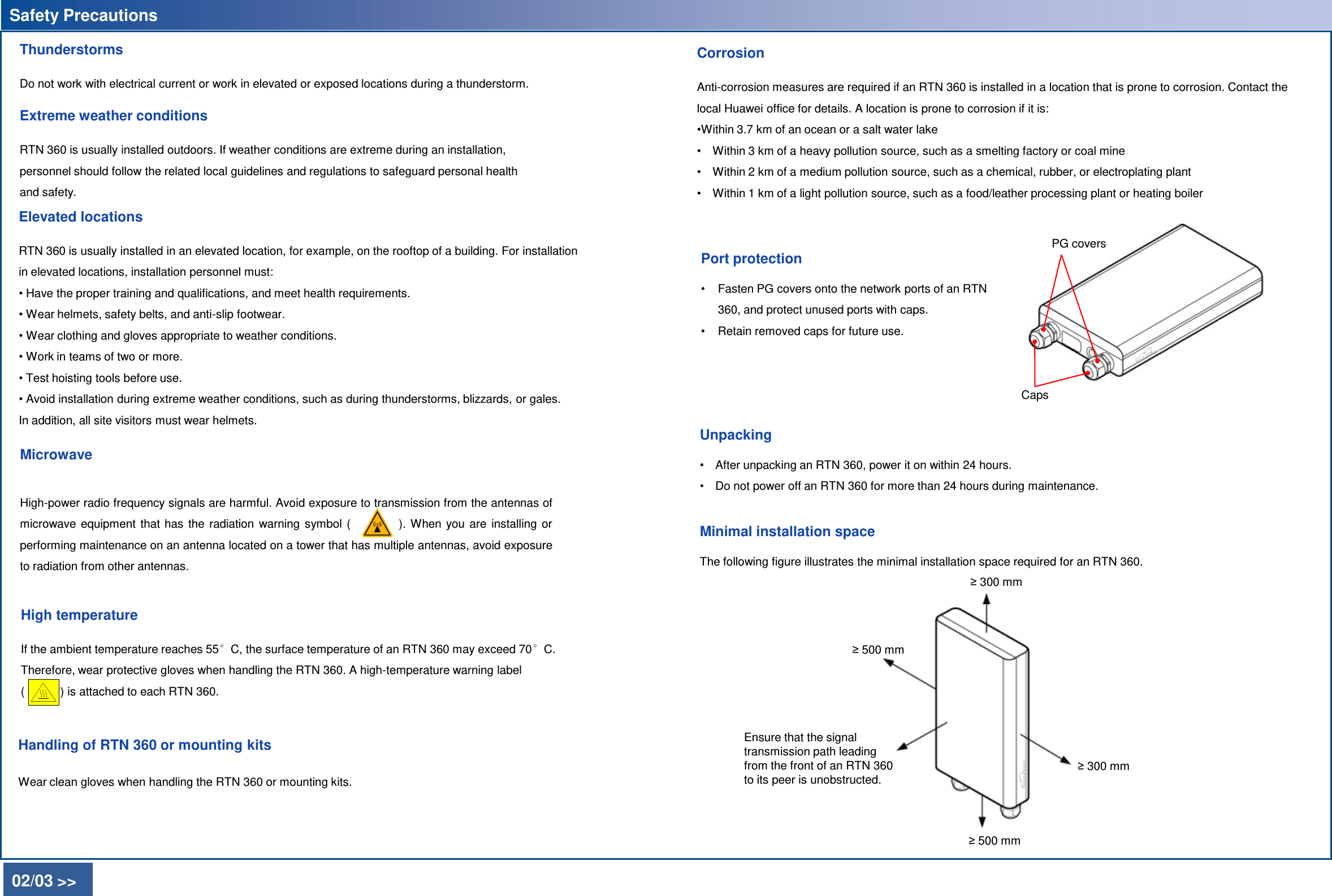
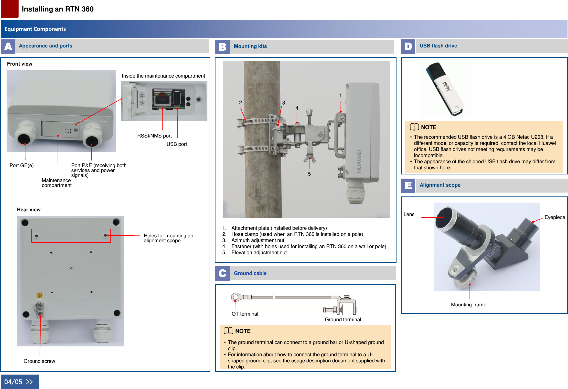
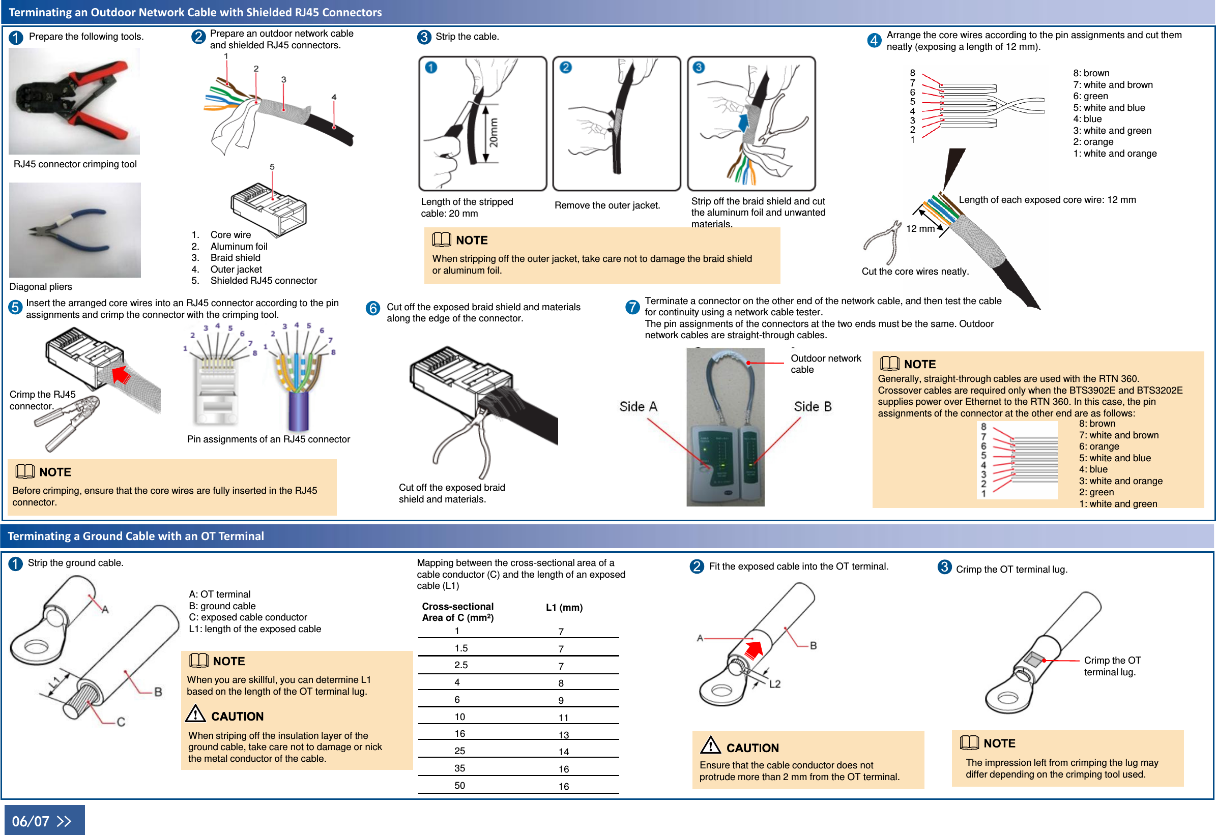
Quick Installation Guide
Contents
1.
Users Manual
2.
Compliance and Safety Manual
3.
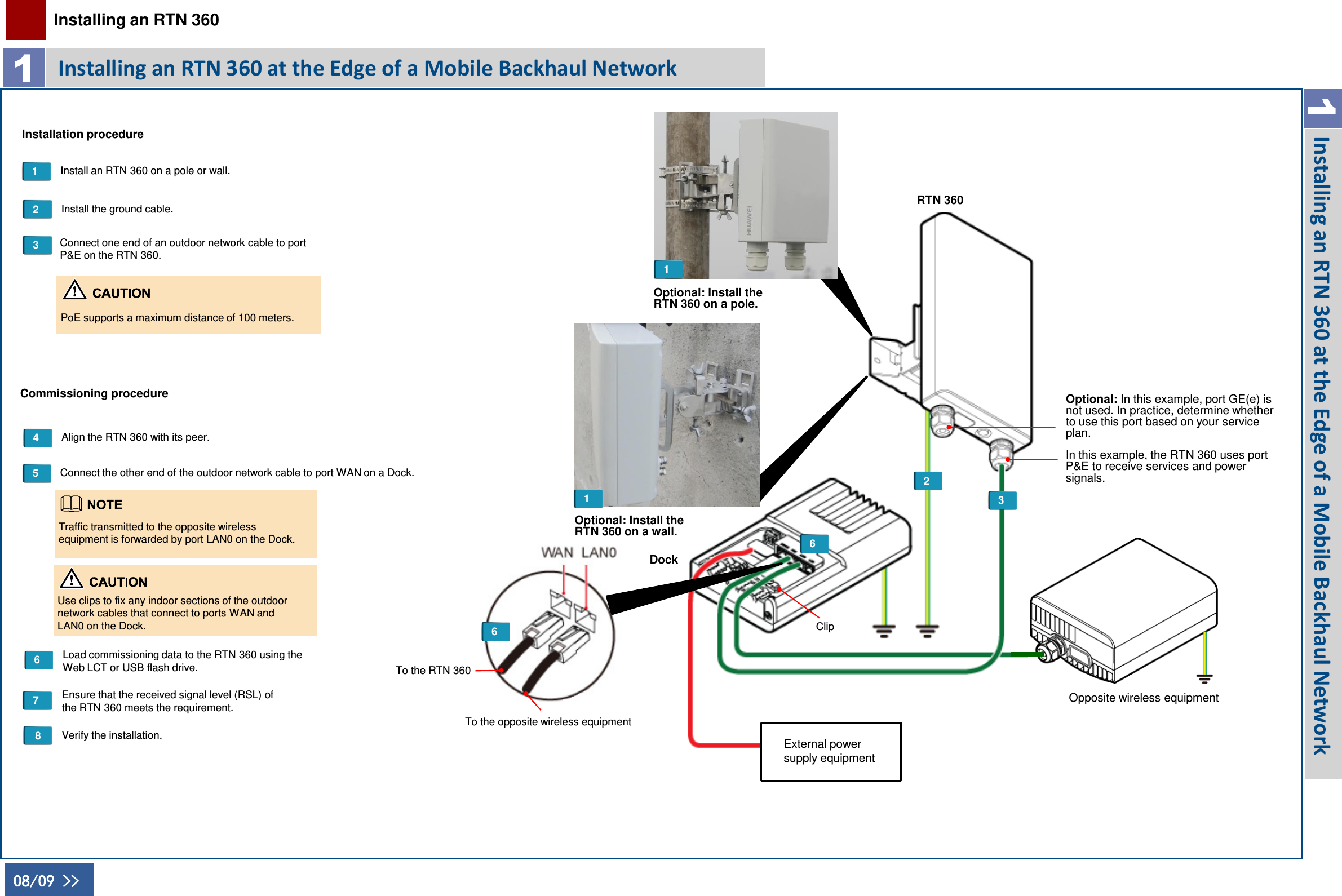
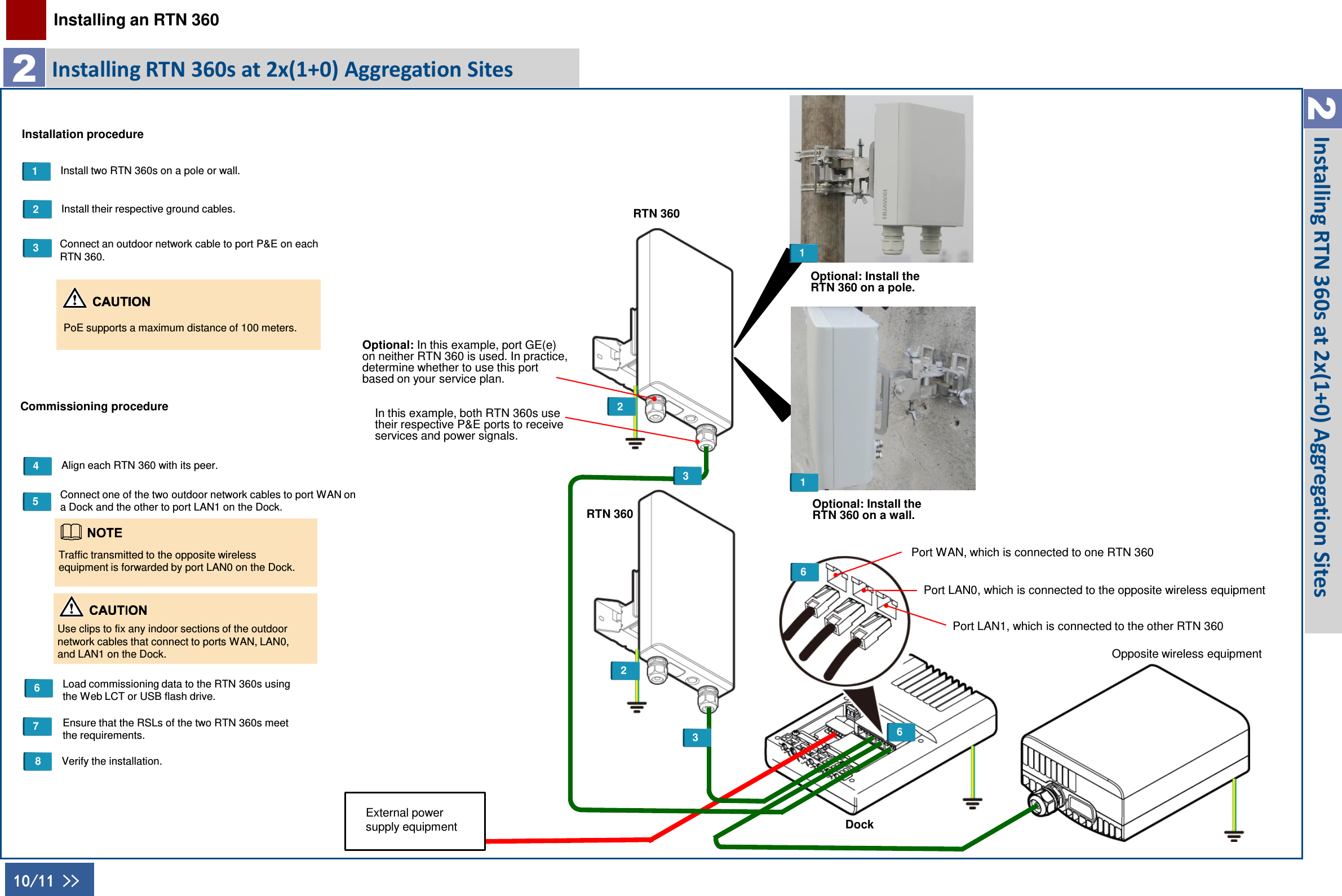
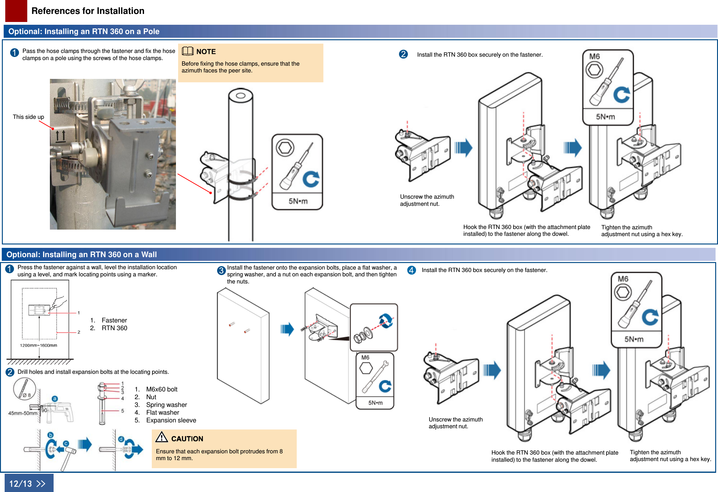
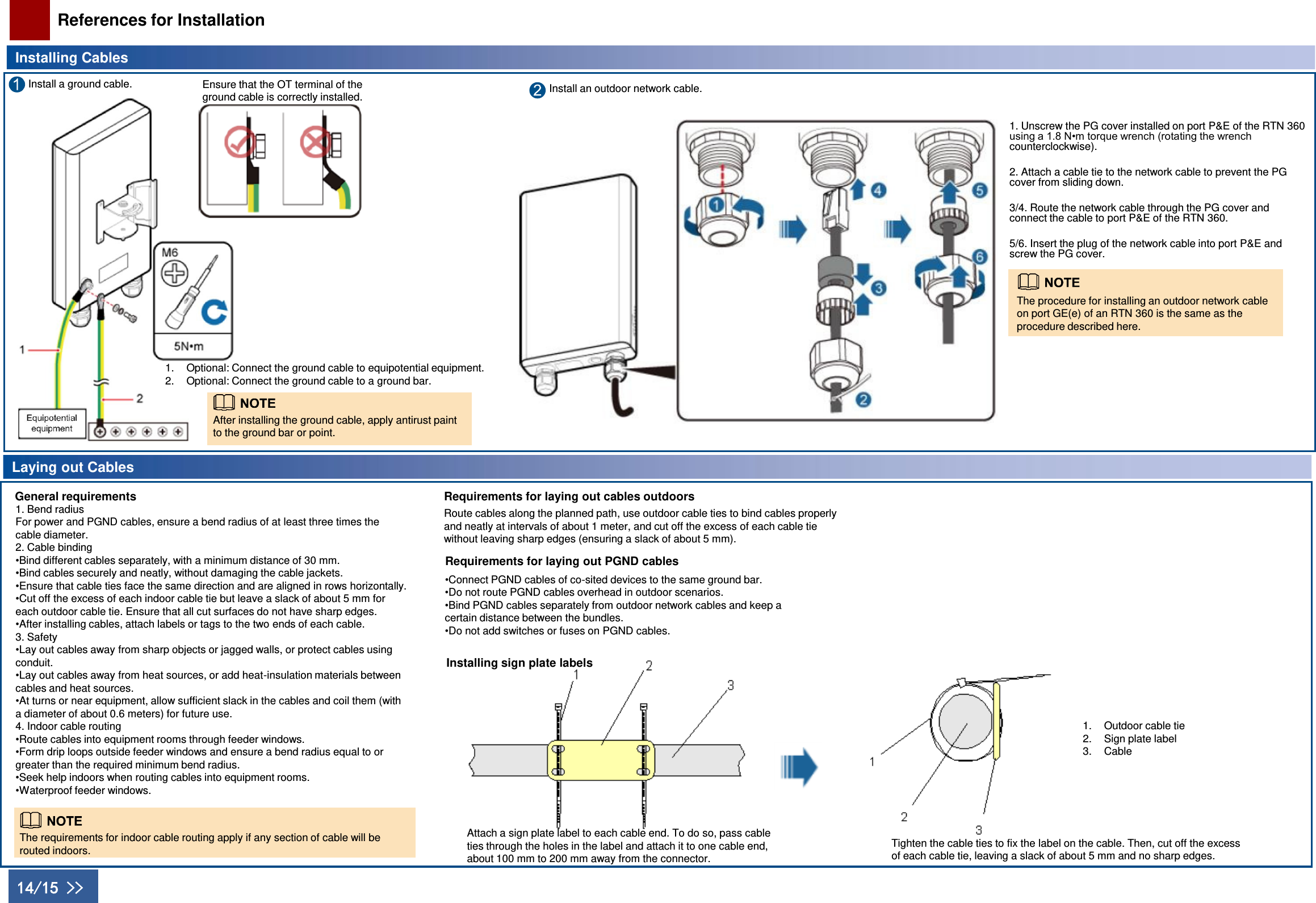
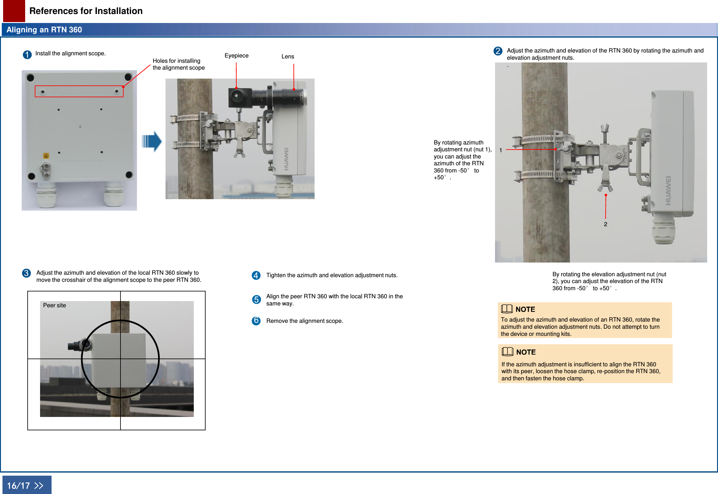
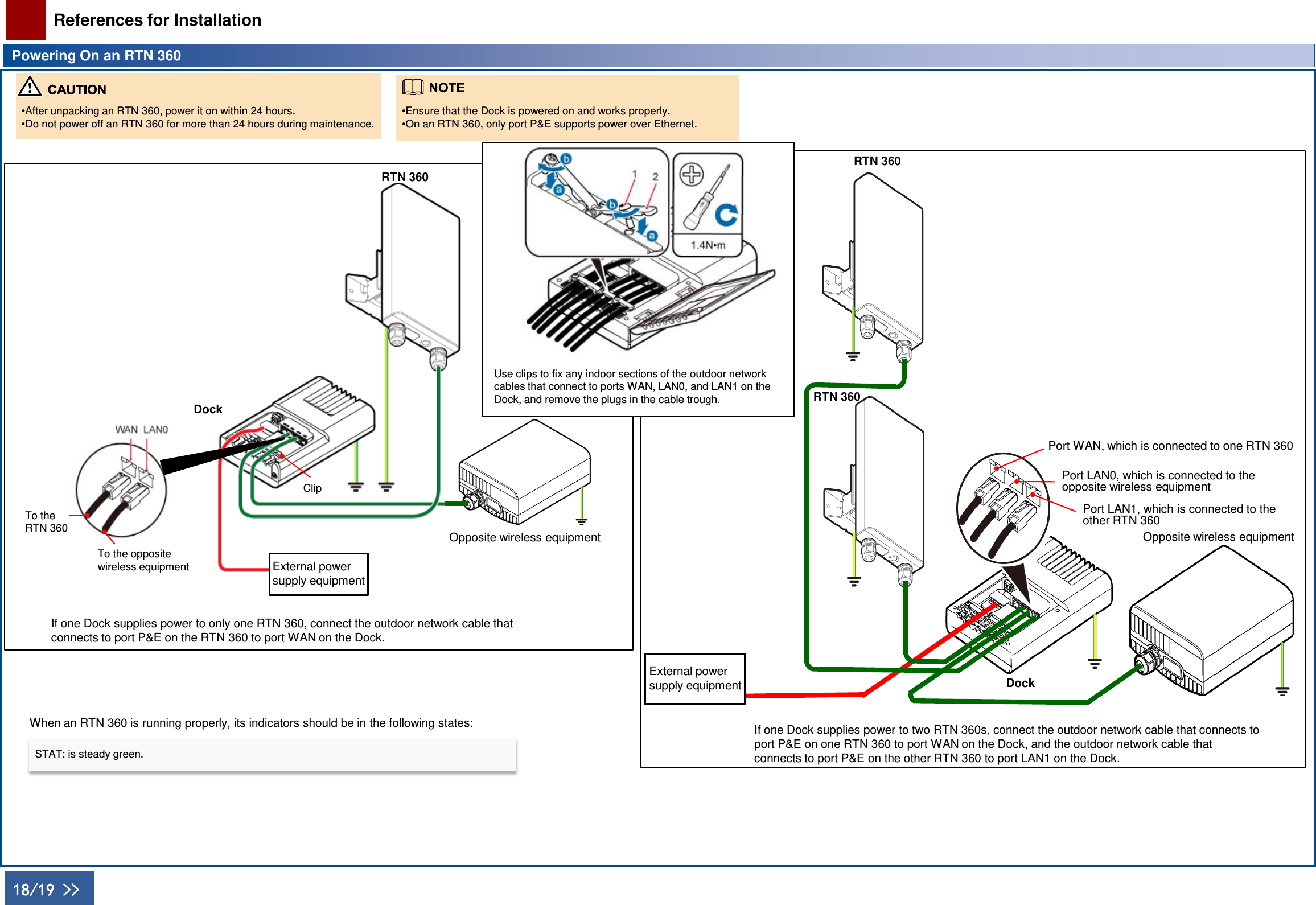
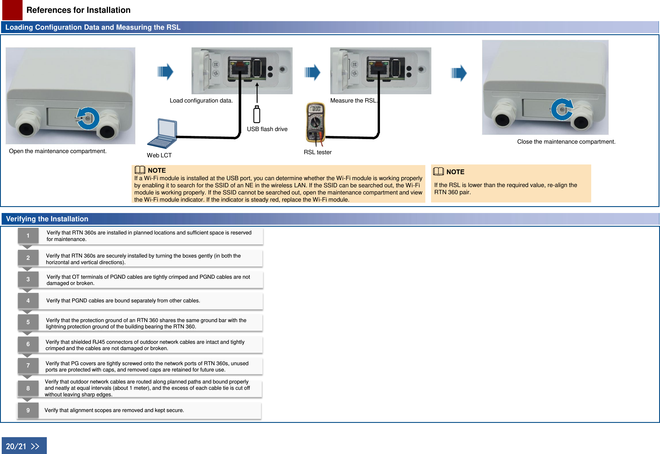
Quick Installation Guide
Quick Installation Guide
Navigation menu
Upload a User Manual
Namespaces
Wiki Guide
HTML
PDF
Info
Views
User Manual
Discussion / Help
Navigation