Huawei Release Notes F Tanjim Qmobile Call Centre Singer Y200 U8655 1. 51053288 U8655N(MTC965) Maintenance Manual V1.0
2014-08-11
User Manual: Huawei
Open the PDF directly: View PDF ![]() .
.
Page Count: 72

U8655N
Maintenance Manual
Issue
1.0
Date
2012-09-27
HUAWEI TECHNOLOGIES CO., LTD.

Issue 1.0 (2012-02-23)
Huawei Proprietary and Confidential
Copyright © Huawei Technologies Co., Ltd.
i
Copyright © Huawei Technologies Co., Ltd. 2012. All rights reserved.
No part of this document may be reproduced or transmitted in any form or by any means without prior
written consent of Huawei Technologies Co., Ltd.
Trademarks and Permissions
and other Huawei trademarks are trademarks of Huawei Technologies Co., Ltd.
All other trademarks and trade names mentioned in this document are the property of their respective
holders.
Notice
The purchased products, services and features are stipulated by the contract made between Huawei and
the customer. All or part of the products, services and features described in this document may not be
within the purchase scope or the usage scope. Unless otherwise specified in the contract, all statements,
information, and recommendations in this document are provided "AS IS" without warranties, guarantees or
representations of any kind, either express or implied.
The information in this document is subject to change without notice. Every effort has been made in the
preparation of this document to ensure accuracy of the contents, but all statements, information, and
recommendations in this document do not constitute a warranty of any kind, express or implied.
Huawei Technologies Co., Ltd.
Address:
Huawei Industrial Base
Bantian, Longgang
Shenzhen 518129
People's Republic of China
Website:
http://www.huawei.com
Email:
support@huawei.com
U8655
Maintenance Manual
About This Document
Issue 1.0 (2012-02-23)
Huawei Proprietary and Confidential
Copyright © Huawei Technologies Co., Ltd.
ii
About This Document
Purpose
Prepared by
R&D
Date
Reviewed by
Maintenance support team
Date
Approved by
Service representative
Date
Change History
Date
Version
Change Reason
Revised Section
Description
Author
2012-02-20
V1.0
Released the first issue.
R&D

U8655
Maintenance Manual
Contents
Issue 1.0 (2012-02-23)
Huawei Proprietary and Confidential
Copyright © Huawei Technologies Co., Ltd.
iii
Contents
About This Document .................................................................................................................... ii
1 Product Introduction .................................................................................................................... 1
1.1 Appearance ....................................................................................................................................................... 1
1.2 Specifications ................................................................................................................................................... 1
2 Applicable Scope and Precautions ............................................................................................ 3
2.1 Applicable Scope .............................................................................................................................................. 3
2.2 Precautions ....................................................................................................................................................... 3
2.3 How to Obtain Product and Repair Information .............................................................................................. 3
3 Exploded View............................................................................................................................... 4
4 Components on the PCBA ........................................................................................................... 6
5 Software Upgrade ......................................................................................................................... 8
5.1 Upgrade Preparation ......................................................................................................................................... 8
5.2 Upgrade Procedure ........................................................................................................................................... 8
6 Maintenance Tools ...................................................................................................................... 10
7 Disassembly Procedure .............................................................................................................. 12
8 Assembly Procedure ................................................................................................................... 17
9 Principles and Failure Analysis ............................................................................................... 21
9.1 Block Diagram ............................................................................................................................................... 21
9.1.1 Function Description of the PCBA ....................................................................................................... 22
9.2 Baseband Unit ................................................................................................................................................ 25
9.2.1 Power-on Management Circuits ............................................................................................................ 25
9.2.2 Charging Management Circuits ............................................................................................................ 29
9.3 RF Unit ........................................................................................................................................................... 30
9.3.1 RF Failure ............................................................................................................................................. 30
9.3.2 GPS ....................................................................................................................................................... 33
9.3.3 Wi-Fi/Bluetooth/FM Module ................................................................................................................ 33
9.4 Peripheral Circuits .......................................................................................................................................... 34
9.4.1 Display .................................................................................................................................................. 34
9.4.2 Camera .................................................................................................................................................. 37

U8655
Maintenance Manual
Contents
Issue 1.0 (2012-02-23)
Huawei Proprietary and Confidential
Copyright © Huawei Technologies Co., Ltd.
iv
9.4.3 USB ....................................................................................................................................................... 39
9.4.4 Headset Jack.......................................................................................................................................... 40
9.4.5 Keys ...................................................................................................................................................... 42
9.4.6 Status Indicator and Touch Key Backlight Circuits .............................................................................. 43
9.4.7 Battery Connector ................................................................................................................................. 44
9.4.8 Accelerometer ....................................................................................................................................... 45
9.4.9 Proximity and Illuminance Sensor ........................................................................................................ 45
9.4.10 Vibration Motor ................................................................................................................................... 47
9.4.11 Receiver .............................................................................................................................................. 48
9.4.12 Microphone ......................................................................................................................................... 50
9.4.13 Touchscreen Panel ............................................................................................................................... 51
9.4.14 SIM Card ............................................................................................................................................. 52
9.4.15 microSD Card ..................................................................................................................................... 53
9.4.16 NFC ..................................................................................................................................................... 54
10 Solder Points on the PCB and BGA Chip............................................................................. 59
11 Functional Tests......................................................................................................................... 64
11.1 MMI Test ...................................................................................................................................................... 64
11.2 Voice Call Test .............................................................................................................................................. 67
U8655
Maintenance Manual
1 Product Introduction
Issue 1.0 (2012-02-23)
Huawei Proprietary and Confidential
Copyright © Huawei Technologies Co., Ltd.
1
1 Product Introduction
1.1 Appearance
1.2 Specifications
Category
Description
Dimensions (H x W x D)
116.9 mm x 61.4 mm x 12.2 mm
Technical standard
U8655N: W2100/W900, GSM850/900/1800/1900
U8655
Maintenance Manual
1 Product Introduction
Issue 1.0 (2012-02-23)
Huawei Proprietary and Confidential
Copyright © Huawei Technologies Co., Ltd.
2
Category
Description
Frequency bands
U8655N:
- WCDMA 900MHz: 880–915 MHz (UL), 925–960 MHz (DL))
- WCDMA 2100 MHz: 1920–1980 MHz (UL), 2110–2170 MHz (DL)
- GSM 850 MHz: 824–849 MHz (UL), 869–894 MHz (DL)
- GSM 900 MHz: 880–915 MHz (UL), 925–960 MHz (DL)
- GSM 1800 MHz: 1710–1785 MHz (UL), 1805–1880 MHz (DL)
- GSM 1900 MHz: 1850–1910 MHz (UL), 1930–1990 MHz (DL)
Weight
< 125 g with battery
Form factor
Bar
Antenna
Built-in
UIM
SIM, USIM
Charger
5 V, 1000 mA
Battery
Type: Li-ion
Capacity: 1250 mAh
Standby time: 220–250 hours (network dependent)
Talk time: 210 minutes (network dependent)
Display
Resolution
320 x 480 pixels
Type
TFT LCD
Color
262K
Size
3.5 inches
Connectors
Charging port
micro-USB connector
USB port
micro-USB connector
microSD card
interface
microSD card interface
Headset jack
3.5 mm (LRGM)
Maximum
transmission
power
23–33 dBm
Static
sensitivity
≤ 104 dBm
Temperature
Operating temperature: 0°C to +40°C
Storage temperature: –20°C to +50°C
Humidity
Operating humidity: 5% to 95% RH
U8655
Maintenance Manual
2 Applicable Scope and Precautions
Issue 1.0 (2012-02-23)
Huawei Proprietary and Confidential
Copyright © Huawei Technologies Co., Ltd.
3
2 Applicable Scope and Precautions
2.1 Applicable Scope
This document provides repair instructions for technicians at service centers authorized by
Huawei. This maintenance manual is confidential and accessible to authorized service centers
(ASCs) and authorized service providers (ASPs) only. While every effort has been made to
ensure the accuracy of this document, errors may still exist. If you find any errors or have any
suggestions, please contact Huawei’s customer service.
2.2 Precautions
- Only qualified technicians are allowed to perform repair and calibration.
- Perform all operations in electrostatic discharge (ESD) rooms and wear ESD wrist straps
throughout the operations.
- Ensure that all components, screws and insulators are properly installed after repair and
calibration, and that all cables and wires are installed and connected correctly.
- Ensure that the soldering is lead-free and compliant with eco-friendly requirements.
2.3 How to Obtain Product and Repair Information
To obtain description and repair information about Huawei's products, please visit
http://www.huaweidevice.com/worldwide/technicaIndex.do.
ESD is the main cause of damage to electrostatic-sensitive components. Each
ASC must exercise caution to avoid ESD damage and comply with the ESD
protection requirements in this manual.
U8655
Maintenance Manual
3 Exploded View
Issue 1.0 (2012-02-23)
Huawei Proprietary and Confidential
Copyright © Huawei Technologies Co., Ltd.
4
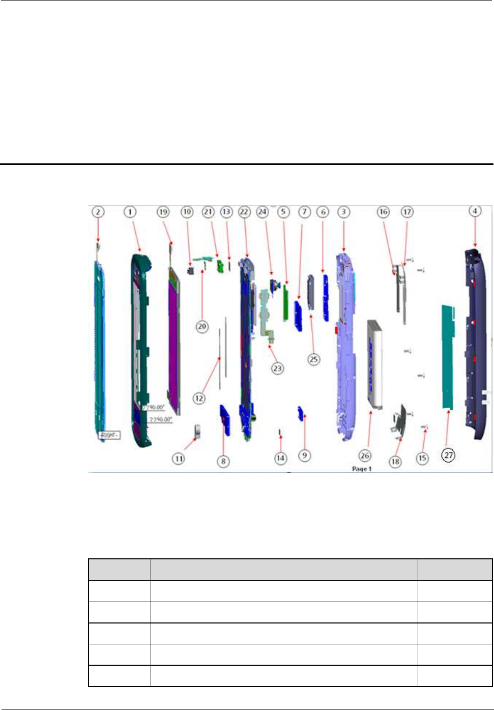
3 Exploded View
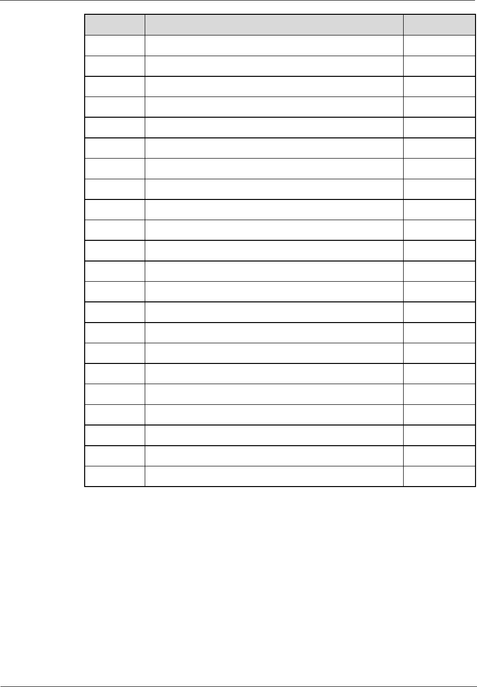
The components listed in the following table are structural parts of the phone, and cannot be
used as reference when requesting spare parts.
Table 3-1 List of components in the exploded view drawing
No.
Item
Quantity
1
U8655N_Cover A assembly
1
2
Touchscreen panel
1
3
U8655N_Cover B assembly
1
4
U8655N_Battery cover assembly
1
5
U8655N_Volume key
1
1
5
U8655
Maintenance Manual
3 Exploded View
Issue 1.0 (2012-02-23)
Huawei Proprietary and Confidential
Copyright © Huawei Technologies Co., Ltd.
5
No.
Item
Quantity
6
U8655N_Speaker shielding cover
1
7
U8655N_CPU shielding cover
1
8
U8655N_RTR shielding cover
1
9
U8655N_PA shielding cover
1
10
U8655N_Proximity and illuminance sensor sealing sheath
1
11
U8655N_MIC_sheath
1
12
U8655N_LCD_conductive fabric
2
13
U8655N_Headset insulation film
1
14
U8655N_USB_adhesive film
1
15
Screw M1.4*3.5
1
16
Diversity antenna and Wi-Fi antenna
1
17
Bluetooth antenna
1
18
Main antenna
1
19
LCD
1
20
Power key flexible flat cable (FFC)
1
21
Receiver
1
22
PCBA
1
23
Volume key FFC
1
24
Camera
1
25
Speaker
1
26
Battery
1
27
NFC antenna
1
U8655
Maintenance Manual
4 Components on the PCBA
Issue 1.0 (2012-02-23)
Huawei Proprietary and Confidential
Copyright © Huawei Technologies Co., Ltd.
6
4 Components on the PCBA
J1001camera connector
Failure of this component
can cause:
Camera shooting failure.
J1401 SIM card holder
Failure of this component
can cause:
SIM card failure.
J1402 SD card holder
Failure of this component
can cause:
SD card failure.
U601 Flash memory chip
Failure of this component
can cause:
Power-on failure, software
are malfunction.
U401 CPU, MSM7225A
Failure of this component
can cause:
Power-on failure, phone
system crash, RF failure.
U4401 NFC module
Failure of this component
can cause:
NFC function failure.
U3302 power module, PA
Failure of this component
can cause:
W2100MHz transmission
failure.
U902 motor
Failure of this component
can cause:
Vibration failure.
U3304 duplexer
Failure of this component
can cause:
W2100MHz transmission
and reception failure.
U1402 SD card filter
Failure of this component
can cause:
SD card failure.
U1303 voltage regulator
Failure of this component
can cause:
LCD backlight failure.
U6000 Wi-Fi/Bluetooth/FM
3-in-1 chip
Failure of this component
can cause:
WiFi, Bluetooth and FM
failure.
U201 power management
chip, PM8029
Failure of this component
can cause:
Power-on failure.
X301 crystal oscillator
32.768KHz
Failure of this component
can cause:
Power-on failure.
J1605 ZIF connector
Failure of this component
can cause:
Volume key failure.
U1204 accelerator
Failure of this component
can cause:
Accelerator failure.
U3202 RF switch
Failure of this component
can cause:
RF failure.
U3201 RF connector
Failure of this component
can cause:
RF failure.
J1101 headset jack
Failure of this component
can cause:
Headset failure.
J1601 BTB connector
Failure of this component
can cause:
Touchscreen panel failure.
J902 battery connector
Failure of this component
can cause:
Power-on failure.
U4101 GPS LNA
Failure of this component
can cause:
GPS failure.
J11302 BTB connector
Failure of this component
can cause:
Display failure.
U8655
Maintenance Manual
4 Components on the PCBA
Issue 1.0 (2012-02-23)
Huawei Proprietary and Confidential
Copyright © Huawei Technologies Co., Ltd.
7
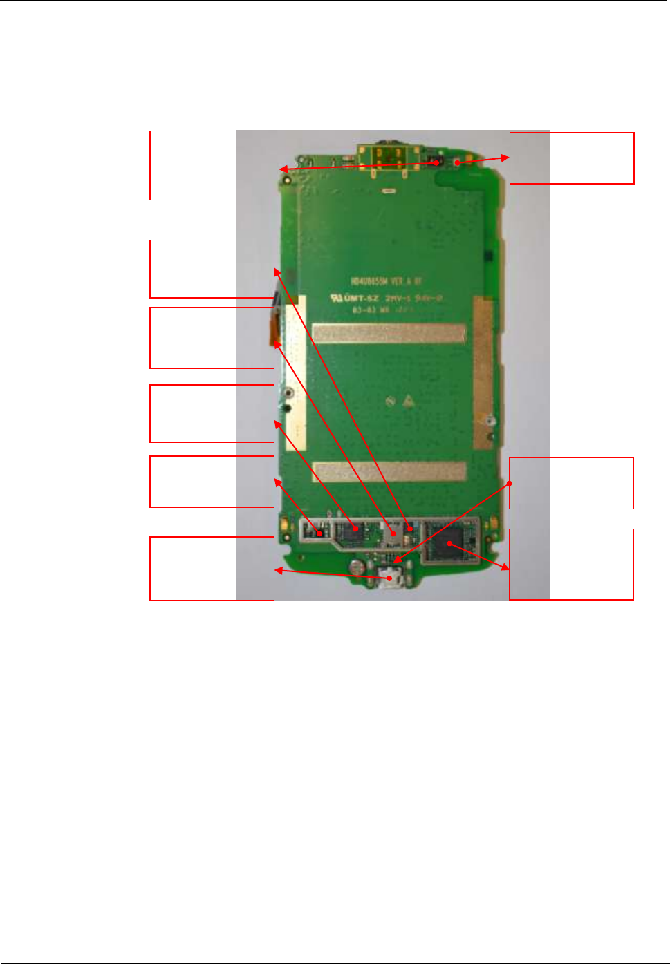
U1207 proximity and
illuminance sensor
Failure of this component
can cause:
Proximity and illuminance
detection failure.
U3404 duplexer
Failure of this component
can cause:
W900MHz transmission
and reception failure.
U3501 power module, PA
Failure of this component
can cause:
GSM transmission failure.
J901 IO connector
Failure of this component
can cause:
Charging failure.
data communication failure.
D1200 tricolor indicator
Failure of this component
can cause:
Tricolor indicator failure.
F901 fuse
Failure of this component
can cause:
Charging failure.
U3401 power module, PA
Failure of this component
can cause:
W900MHz transmission
failure.
U901 DCDC control chip
Failure of this component
can cause:
Charging failure.
U3801 WCDMA/GSM
transmission and
reception chip
Failure of this component
can cause:
RF failure.
U8655
Maintenance Manual
5 Software Upgrade
Issue 1.0 (2012-02-23)
Huawei Proprietary and Confidential
Copyright © Huawei Technologies Co., Ltd.
8
5 Software Upgrade
5.1 Upgrade Preparation
Category
Item
Description
Upgrade
environment
Computer
To copy upgrade software
microSD card
With more than 512 MB free space
Battery
With at least 30% power remaining
Upgrade file
Main upgrade pack
dload/UPDATE.APP
Vendor upgrade pack
vendor_XXX_XXX/UPDATE.APP
Upgrade
method
Using the microSD card
Normal upgrade
Forcible upgrade
5.2 Upgrade Procedure
1. Format the microSD card.
2. Create a folder named dload in the root directory of the microSD card.
3. Copy the upgrade file to the dload folder.
4. Install the microSD card on the phone. Power the phone on, and enter *#*#2846579#*#*
on the idle screen.
5. Select SD Upgrade then Yes to start the upgrade.
6. Before the upgrade, NV items backup is performed (if the phone's NV items has not
been backed up before). Then the phone restarts and the upgrade starts.
7. The upgrade progress is displayed on the LCD.

U8655
Maintenance Manual
5 Software Upgrade
Issue 1.0 (2012-02-23)
Huawei Proprietary and Confidential
Copyright © Huawei Technologies Co., Ltd.
9
8. After the upgrade is completed, the phone restarts and the NV items are restored.
9. After the main upgrade pack is upgraded, upgrade the vendor upgrade pack using the
same upgrade method.
If the phone cannot be properly powered on, use one of the following two methods to forcibly
upgrade the phone:
- Install the battery on the phone (if the screen is jittering, remove the battery and wait for
five seconds before installing the battery again). Press and hold the Volume+ and
Volume– keys, and press the Power key. The phone enters the SD forcible upgrade mode
in which the upgrade process is similar to the normal upgrade.
- While the phone has no battery installed, press and hold the Volume+ and Volume– keys,
and connect the charger to the phone.
The phone enters the SD forcible upgrade. This method is recommended. If the forcible
upgrade still fails, use another microSD card and try forcible upgrade again.
U8655
Maintenance Manual
6 Maintenance Tools
Issue 1.0 (2012-02-23)
Huawei Proprietary and Confidential
Copyright © Huawei Technologies Co., Ltd.
10
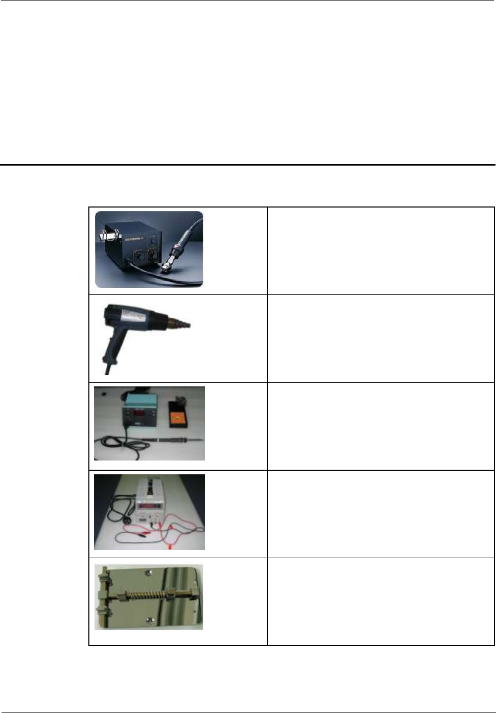
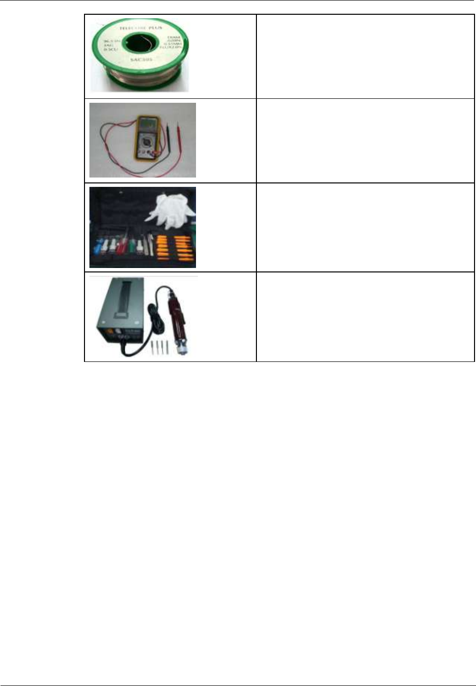
6 Maintenance Tools
Name: constant-temperature hot air blower gun
Usage: to heat components
Name: constant-temperature heat gun
Usage: to heat components
Name: soldering iron
Usage: to solder components
Name: DC regulated power supply
Usage: to supply DC power
Name: soldering table
Usage: to secure the main PCBA
U8655
Maintenance Manual
6 Maintenance Tools
Issue 1.0 (2012-02-23)
Huawei Proprietary and Confidential
Copyright © Huawei Technologies Co., Ltd.
11
Name: lead-free solder wire
Usage: soldering
Name: digital multimeter
Usage: to measure during repair
Name: toolkit
Usage: to assemble and disassemble components
Name: electric screwdriver
Usage: to fasten and remove screws
U8655
Maintenance Manual
7 Disassembly Procedure
Issue 1.0 (2012-02-23)
Huawei Proprietary and Confidential
Copyright © Huawei Technologies Co., Ltd.
12
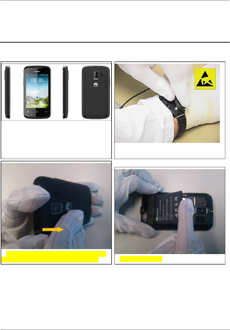
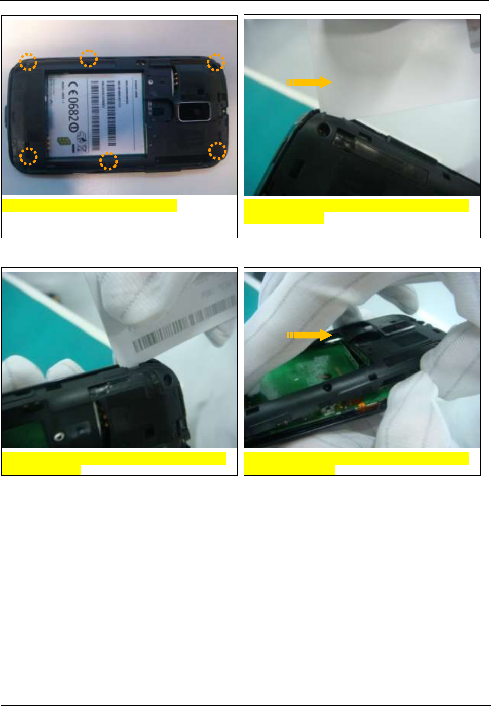
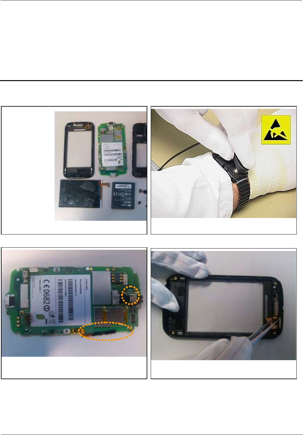
7 Disassembly Procedure
1. Wear an ESD wrist strap, and ensure that the strap is
grounded properly.
2. Remove the battery cover: Press the upper part of
the battery cover and push it towards the bottom.
3. Remove the battery.
U8655N before disassembly
U8655
Maintenance Manual
7 Disassembly Procedure
Issue 1.0 (2012-02-23)
Huawei Proprietary and Confidential
Copyright © Huawei Technologies Co., Ltd.
13
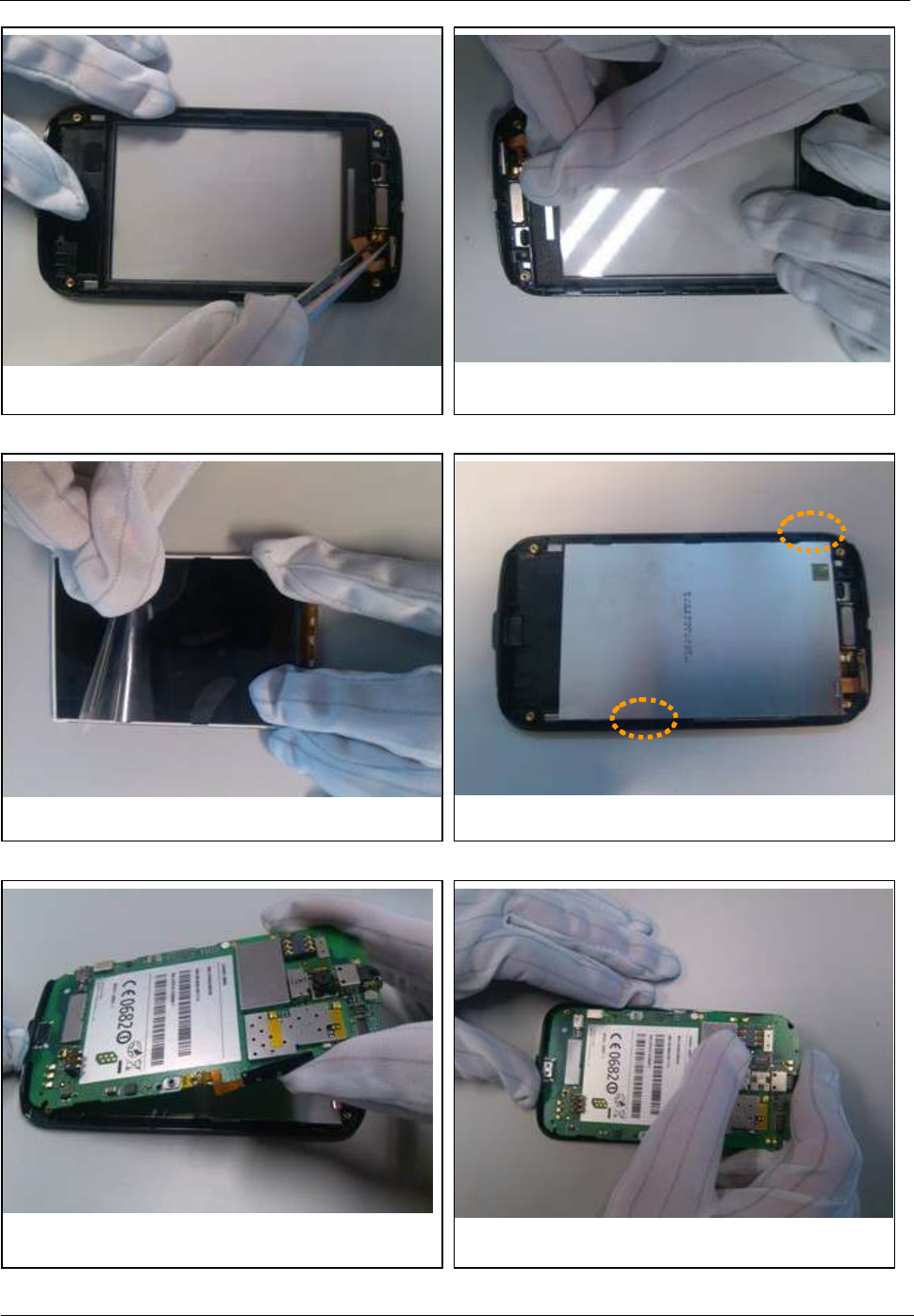
4. Remove the six screws from cover B.
5. Use the disassembly tab to release the latch in the
upper right corner.
6. Use the disassembly tab to release the latch in the
upper left corner.
7. Use a cover opener to release the latches between
cover A and cover B.
U8655
Maintenance Manual
7 Disassembly Procedure
Issue 1.0 (2012-02-23)
Huawei Proprietary and Confidential
Copyright © Huawei Technologies Co., Ltd.
14
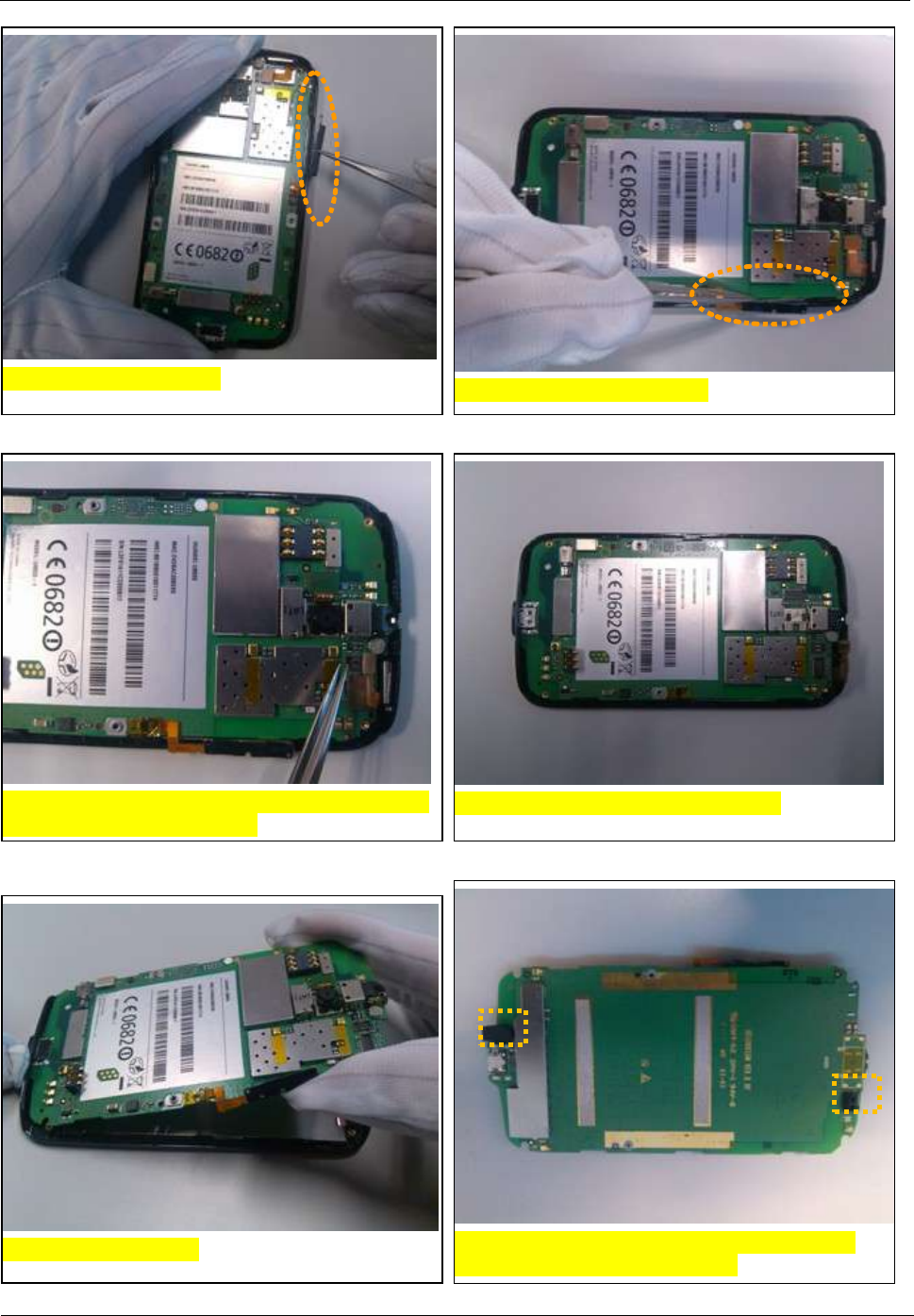
13. Remove the proximity and illuminance sensor
sheath and the microphone sheath.
11. Release the two latches in the PCBA.
10. Disconnect the BTB connector cable between the
touchscreen panel and the LCD.
8. Remove the volume key.
9. Release the volume key FPC.
12. Remove the PCBA.
U8655
Maintenance Manual
7 Disassembly Procedure
Issue 1.0 (2012-02-23)
Huawei Proprietary and Confidential
Copyright © Huawei Technologies Co., Ltd.
15
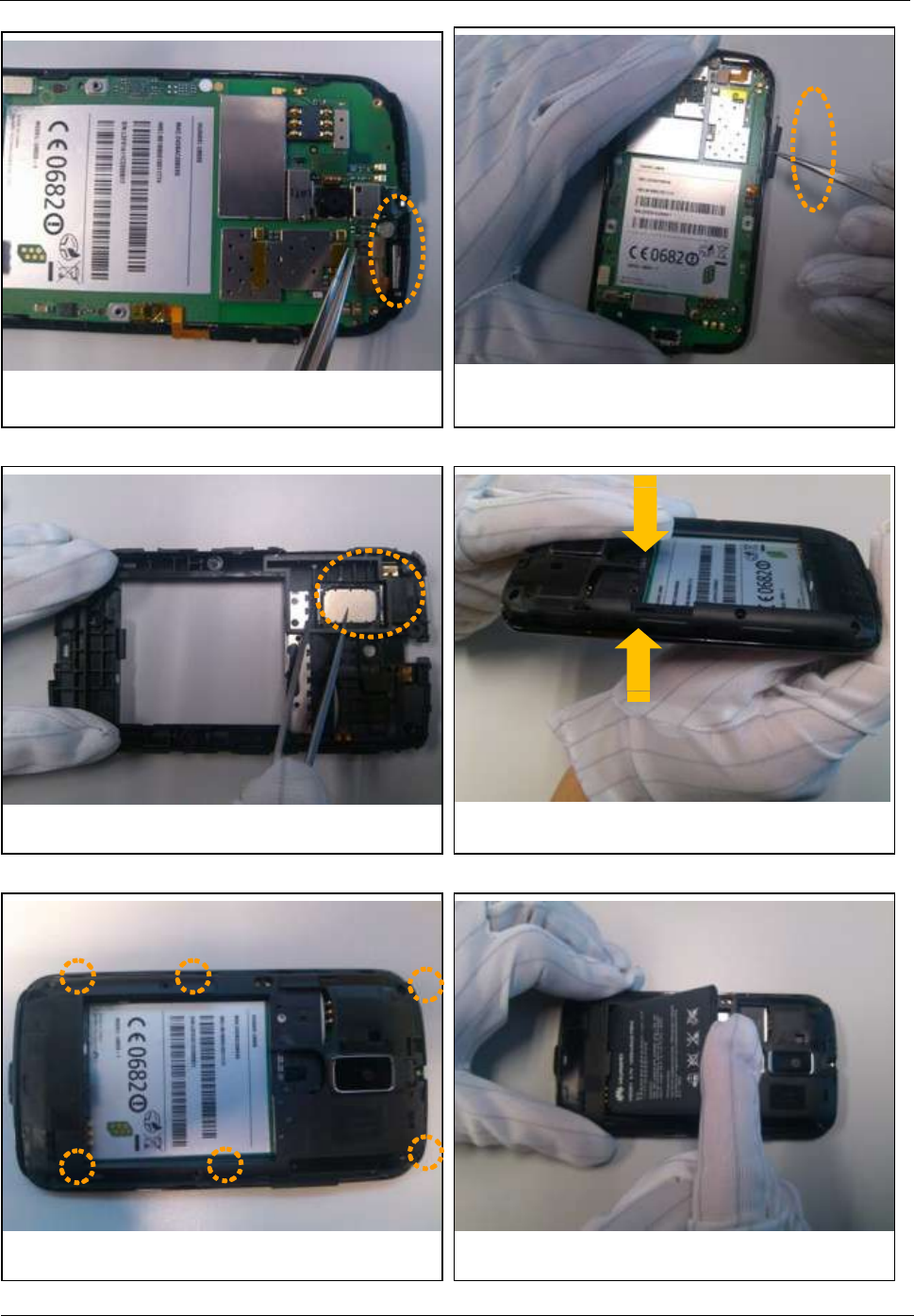
16. Apply a protective film on the LCD.
14. Release the BTB connector, and remove the
camera. Release the ZIF connector, and remove the
volume key FPC.
15. Release the LCD latches, and remove the LCD.
17. Apply a protective film on the inner side of the
touchscreen panel.
U8655
Maintenance Manual
7 Disassembly Procedure
Issue 1.0 (2012-02-23)
Huawei Proprietary and Confidential
Copyright © Huawei Technologies Co., Ltd.
16
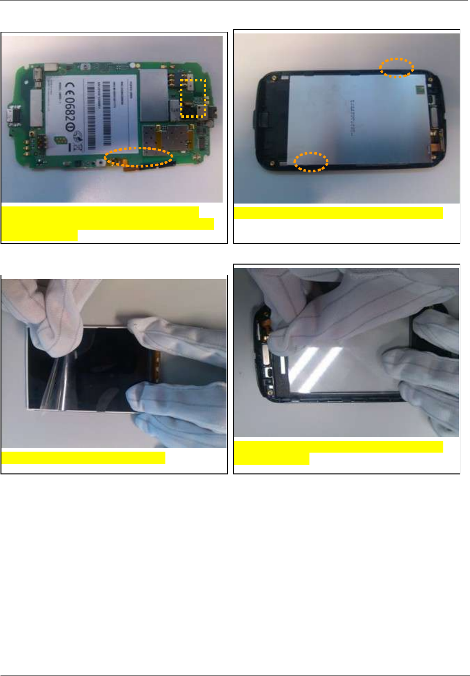
19. Remove the receiver.
20. Remove the speaker.
21. The phone is now disassembled.
18. Remove the Power key FPC.
U8655
Maintenance Manual
8 Assembly Procedure
Issue 1.0 (2012-02-23)
Huawei Proprietary and Confidential
Copyright © Huawei Technologies Co., Ltd.
17
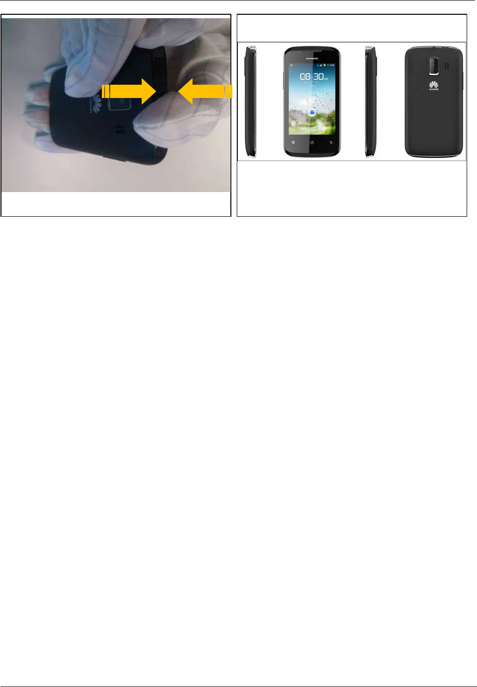
8 Assembly Procedure
U8655N before assembly
1. Wear an ESD wrist strap, and ensure that the strap is
grounded properly.
2. Install the camera on the PCBA, and snap the BTB
connector in place. Install the volume key FPC into the
ZIF connector, and attach the adhesive film.
3. Install the receiver.
U8655
Maintenance Manual
8 Assembly Procedure
Issue 1.0 (2012-02-23)
Huawei Proprietary and Confidential
Copyright © Huawei Technologies Co., Ltd.
18
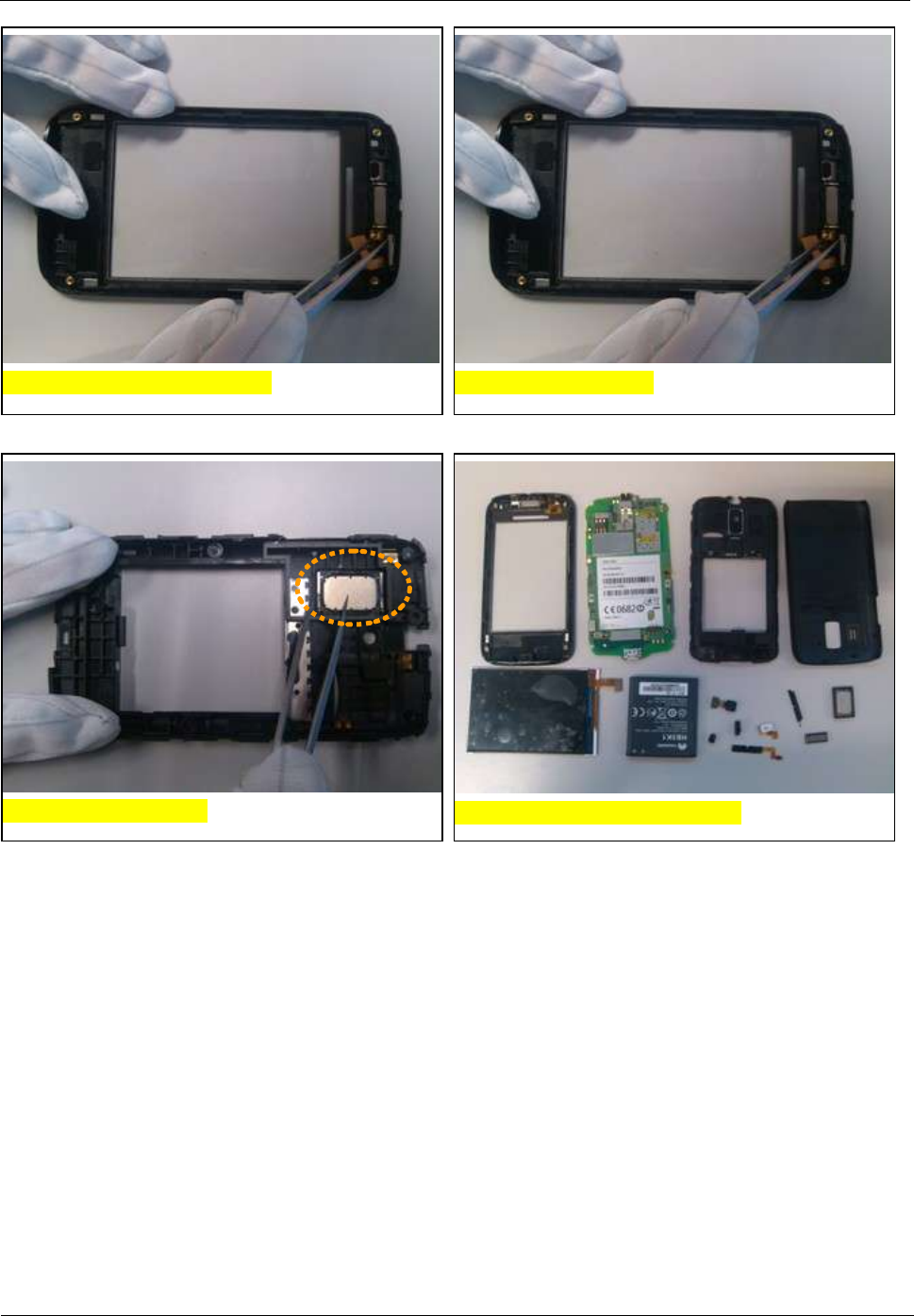
4. Install the Power key FPC.
5. Remove the protective film from the touchscreen
panel.
6. Remove the protective film from the LCD.
7. Install the LCD. Ensure that the two latches are
snapped in place and that the LCD is even.
8. Install the PCBA: Insert the USB port into cover A,
and then snap the PCBA downward in place.
9. Gently press the PCBA to close the latches to secure
the PCBA.
U8655
Maintenance Manual
8 Assembly Procedure
Issue 1.0 (2012-02-23)
Huawei Proprietary and Confidential
Copyright © Huawei Technologies Co., Ltd.
19
14. Install the six screws into cover B.
10. Snap the LCD's BTB connector and then the
touchscreen panel's BTB connector in place.
11. Install the volume key: Attach the volume key FPC
to the metal piece on cover A, and then install the
volume key.
12. Install the speaker.
15. Install the battery: Insert it into the battery
compartment bottom first.
13. Install cover B: Snap cover B's bottom, and press
its top.
U8655
Maintenance Manual
8 Assembly Procedure
Issue 1.0 (2012-02-23)
Huawei Proprietary and Confidential
Copyright © Huawei Technologies Co., Ltd.
20
17. The phone is now assembled.
16. Install the battery cover.
U8655
Maintenance Manual
9 Principles and Failure Analysis
Issue 1.0 (2012-02-23)
Huawei Proprietary and Confidential
Copyright © Huawei Technologies Co., Ltd.
21
9 Principles and Failure Analysis
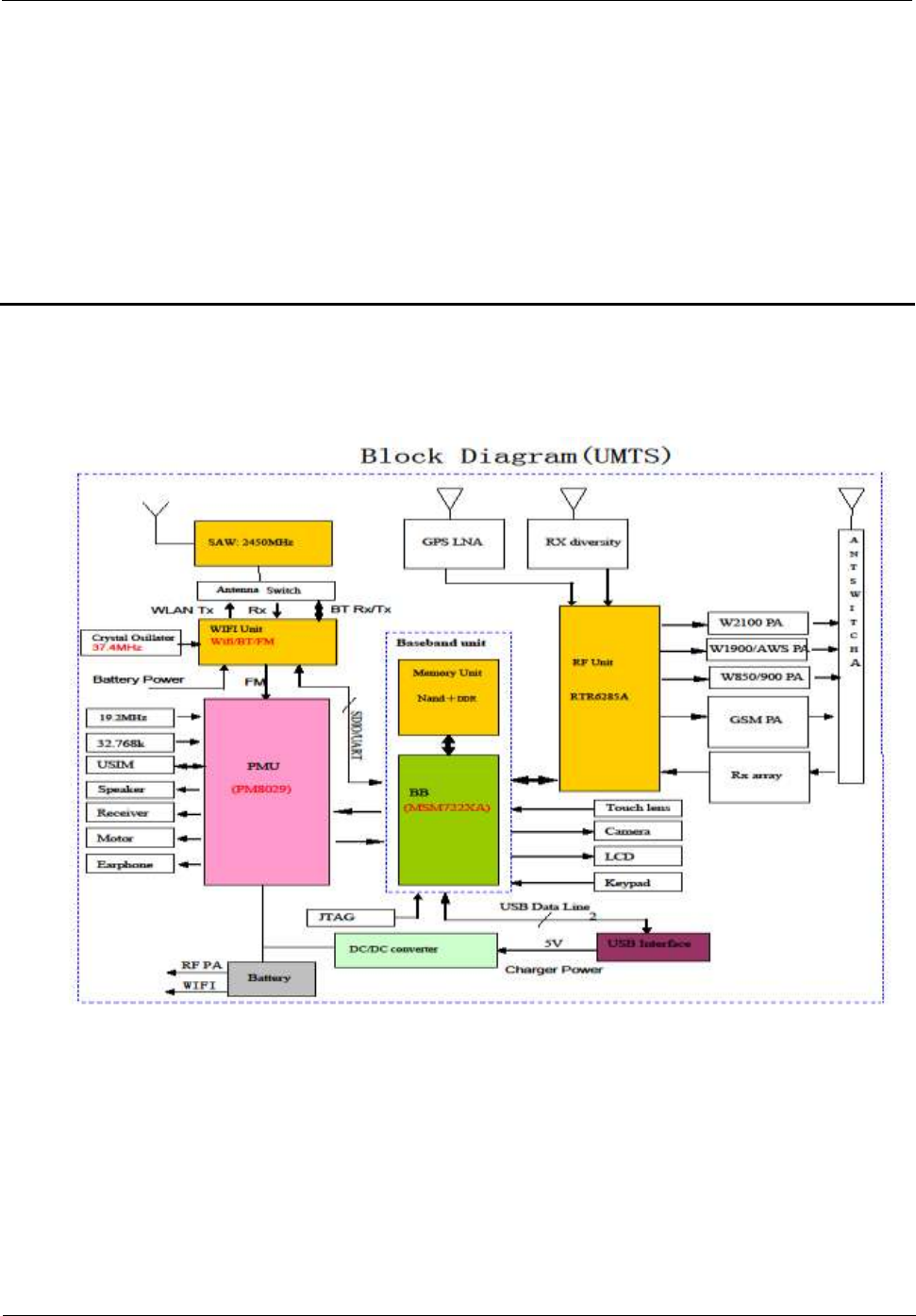
9.1 Block Diagram
The MSM7X2XA (the U8655N uses the MSM7225A) is the baseband signal processing chip,
mainly responsible for processing the input and output of IMGE, VIDEO, AUDIO, MEMEO
SUPPORT, RF INTERFACES, and CONECTIVITY signals. The baseband chip provides
keypad, LCD, SD card, Wi-Fi, Bluetooth, camera, and microphone interfaces.
The PM8029 is mainly responsible for:
Detecting the connection and disconnection of the external power supply.
Supplying power to the phone.
U8655
Maintenance Manual
9 Principles and Failure Analysis
Issue 1.0 (2012-02-23)
Huawei Proprietary and Confidential
Copyright © Huawei Technologies Co., Ltd.
22
Providing analog multi-channel switch, real-time clock circuit, TCXO clock circuit, motor
driver circuit, and speaker driver circuit.
The RTR6285A is the RF signal processing chip, responsible for converting UMTS/GSM
uplink/downlink RF signals and using I/Q signals to exchange data with the baseband chip.
9.1.1 Function Description of the PCBA
The PCBA can be divided into four sub-systems: baseband, RF, power supply, and user
interfaces. The following table describes the subsystems' modules and units, as well as their
functions.
Table 9-1 PCBA subsystems' modules, units, and functions
Subsystem
Module
Unit
Function
Baseband
subsystem
MSM7225A
Modem subsystem
The modem subsystem includes the ARM11
processor, modem DSP, modem AHB bus,
interruption controller, and sleep controller.
The ARM9 is a 400 MHz modem processor,
responsible for modulation and demodulation of
WCDMA, GPS, and GSM signals.
Application
subsystem
The subsystem includes ARM A5 processor,
application DSP, and dedicated data mover.
The A5 processor has a clock rate of 800 MHz,
supporting function modules such as the microSD
card, EBI2, UART/USIM, I2C, GPIO, and clock
modules.
User interface
processing unit
Provides camera, PCM, broadband codec, vocoder,
RF, HKADC, LCD, SD card, USB, UART, USIM
card, SBI, GPIO, JTAG/ETM, and keypad
interfaces.
Multimedia and
game engine
The multimedia and game engine is an MPEG/JPEG
hardware engine providing Java acceleration and
MP3/MMS/MIDI/VR processing functions.
PM8029
Power supply voltage
monitoring
Lists objects being monitored, such as the external
power supply input, Li-ion battery, and charger.
Temperature
monitoring
Monitors the battery temperature.
NAND flash
memory
File system support
Stores applications and NV items. Capacity: 4 GB.
DDR1 RAM
Random access
memory
Provide storage space for running applications.
Capacity: 2 GB.
RF
subsystem
WCDMA, and
GSM/DCS
signal
transmission and
reception
AFC circuit, APC
circuit, AGC circuit
Performs the RF function of WCDMA signal
reception and transmission.
Mainly includes the RTR6285A RF chip and the
peripheral circuit.
U8655
Maintenance Manual
9 Principles and Failure Analysis
Issue 1.0 (2012-02-23)
Huawei Proprietary and Confidential
Copyright © Huawei Technologies Co., Ltd.
23
Subsystem
Module
Unit
Function
GPS
GPS reception
Receives and processes GPS signals.
Mainly includes the RTR6285A chip and the
peripheral circuit.
Bluetooth
interface
Bluetooth/Wi-Fi/FM
3-in-1 module
Performs baseband functions for Bluetooth, Wi-Fi
and FM signals.
Transmits and receives Bluetooth, Wi-Fi and FM
signals.
Mainly includes the Bluetooth/Wi-Fi/FM module
and its peripheral circuit.
Wi-Fi interface
Same as the
Bluetooth interface
Same as the Bluetooth interface
Oscillator and
frequency
synthesizer
Crystal oscillators
Generates highly accurate VCTCXO frequency for
the 19.2 MHz local reference clock. The RTR6285A
has a built-in local oscillator (LO) providing clock
frequency for transmitting and receiving WCDMA
and GPS signals.
Antenna
External antenna,
internal interface
component, antenna
protection
The phone uses internal antennas for wireless
communication, supporting WCDMA high and low
frequency bands.
The antennas are the main antenna, GPS antenna,
diversity antenna, Wi-Fi/Bluetooth antenna, FM
antenna (headset) and NFC antenna.
Coupler
Power coupler
Couples part of the power output from the WCDMA
power amplifier to the RTR6285A for power
monitoring.
User
interface
subsystem
UART interface
MSM7225A subsystem's UART1 interface for
Bluetooth.
USB interface
Driver, protection
circuit, output
interface component
The peripheral circuit, protection circuit and
interface connectors of the USB interface in the
MSM7225A subsystem.
It is the major data service channel for the
engineering sample, and can be used to debug and
test devices during R&D.
USIM card
interface
Power supply,
protection circuit,
USIM card holder
Mainly includes the USIM card holder and related
connection circuits.
Keypad and
backlight
Keypad driver
circuit, external
keypad, backlight
LED control circuit
Supports GPIO for keypad scanning.
Provides backlight LED. When a key is pressed, the
backlight is on.
Works in conjunction with PM8029 to provide the
keypad backlight brightness adjustment function.
Color LCD and
backlight
LCD driver, interface
mode, and backlight
control
The phone's LCD with 256K colors. The brightness
of the LCD backlight can be adjusted by users.
U8655
Maintenance Manual
9 Principles and Failure Analysis
Issue 1.0 (2012-02-23)
Huawei Proprietary and Confidential
Copyright © Huawei Technologies Co., Ltd.
24
Subsystem
Module
Unit
Function
Speaker
Driver mode,
connection mode,
speaker component
Plays polyphonic ringtones for incoming calls.
The maximum power of the speaker is 500 mW.
It has good frequency response for playing
20–20000 Hz ringtones. It can also play
monophonic MP3 audio files.
Receiver
Driver mode,
connection mode,
receiver component
Emits sound during a call.
Microphone
Interface circuit,
connection mode,
microphone
component
The phone has two built-in microphones to
eliminate the environmental noise.
Earphone
Earphone, headset
interface circuit,
microphone interface
circuit
The phone provides a headset jack to output music
playback audio or voice during a call. The
microphone on the headset cable can pick sound and
input it into the phone. TheU8655N supports only
the LRGM headsets.
Vibration motor
interface
Driver mode,
connection mode,
motor
When there is an incoming call, the motor can
vibrate notify the user of the call.
NFC
I2C interface control
Performs proximity sensing function.
Proximity and
illuminance
sensor
I2C interface control
Senses the intensity of environmental light for
adjusting the LCD and keypad backlight brightness.
Detects the distance between the phone and the
user's skin and turns the LCD and touchscreen panel
off when the distance is smaller than the specified
value.
Accelerometer
I2C interface control
Senses acceleration to help implement game
functions.
Battery
Li-ion battery
3.7 V/1250 mAh (the battery must be certified and
comply with relevant safety regulations).
Power
supply
subsystem
External power
supply (travel
charger)
Adapter, and
interface component
The charger meets the requirements of China,
Europe, the USA, and Australia.
Charger specifications: 90–240 V, 45–55 Hz, AC
input. The model differs with different markets.
The output voltage of the charger is 5±0.25 V.The
charger must be CE and CCC certified.
The charger's output current must be able to charge
the battery and supply power to the phone for
normal operation at the same time.
U8655
Maintenance Manual
9 Principles and Failure Analysis
Issue 1.0 (2012-02-23)
Huawei Proprietary and Confidential
Copyright © Huawei Technologies Co., Ltd.
25
Subsystem
Module
Unit
Function
Power
distribution
network and
power
management
function
Power distribution
network
Includes filter networks and PCB traces for the
power supply.
PM8029
enhanced
function
Battery management,
charging circuit,
charging mode, and
charging protection
Manages battery charging and discharging, provides
overcharging and over-discharging protection, and
charges the capacitor that supplies power to
maintain the real-time clock (RTC).
Board circuit power
management
(power-on/off
analysis)
Mainly controls the low-dropout (LDO) regulator
power supply to flexibly manage power supply.
Based on the service status and the requirements of
the interface power supply specifications and
power-saving analysis, the board software manages
the power supplies to the units on the board to
reduce power consumption.
RTC
The built-in RTC circuit uses a sleep clock of
32.768 kHz to provide precise time.
HKADC
Contains 8 MPP interfaces. Analog-to-digital
conversion can be implemented inside the PM8029.
TCXO driver
The PM8029 has a built-in TCXO driver providing
two analog signal output channels and two digital
signal output channels.
UVLO
Provides the Undervoltage-Lockout (UVLO)
function. When the input voltage is lower than the
threshold for a specific period of time, the phone
powers off.
Over temperature
protection
When the on-chip junction temperature exceeds
150°C, the phone powers off.
Internal driver circuit
Provides one vibration motor driver and one speaker
driver.
Interrupt
management
The built-in interrupt manager handles related
interrupt signals.
USB driver
Supports USB 2.0; does not support USB OTG.
9.2 Baseband Unit
9.2.1 Power-on Management Circuits
On the U8655N, most power supplies are provided by the power management chip PM8029.
U8655
Maintenance Manual
9 Principles and Failure Analysis
Issue 1.0 (2012-02-23)
Huawei Proprietary and Confidential
Copyright © Huawei Technologies Co., Ltd.
26
The PM8029 provides two types (switched-mode power supply and LDO regulators) of
programmable voltage regulators with a total of 24 output channels.
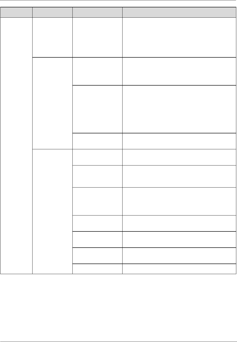
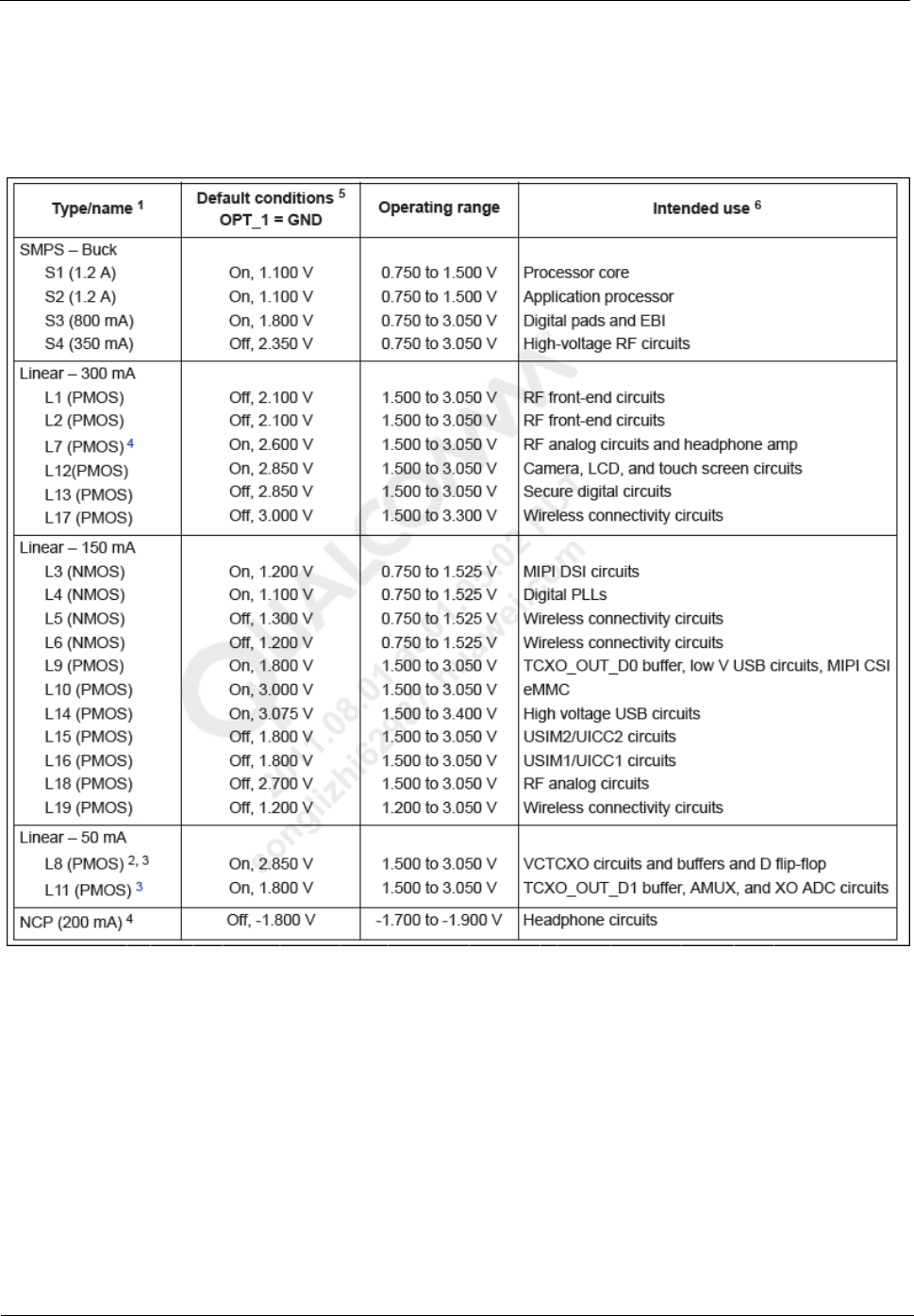
The follow table lists the voltage regulator parameters.
Table 9-2 Voltage regulator specifications
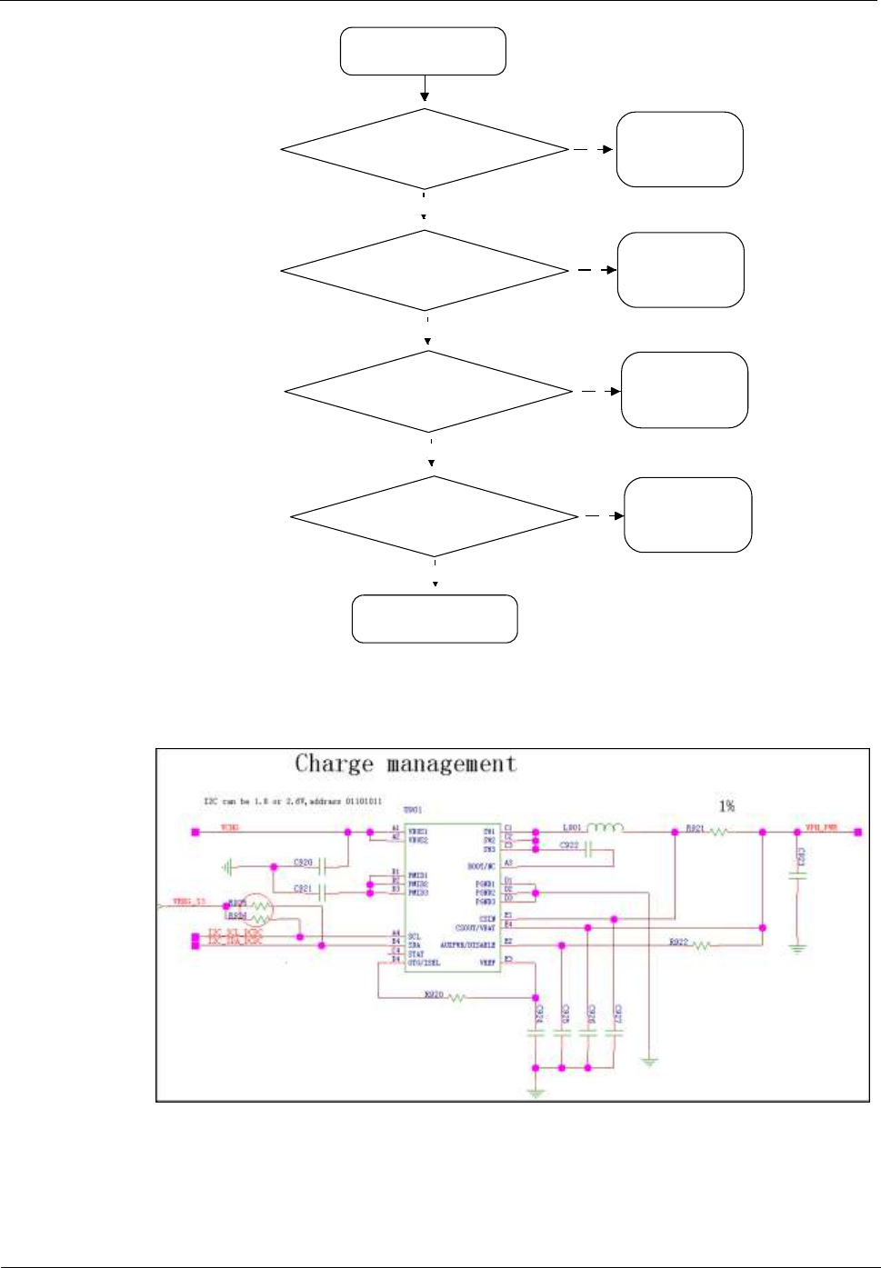
Troubleshooting Process
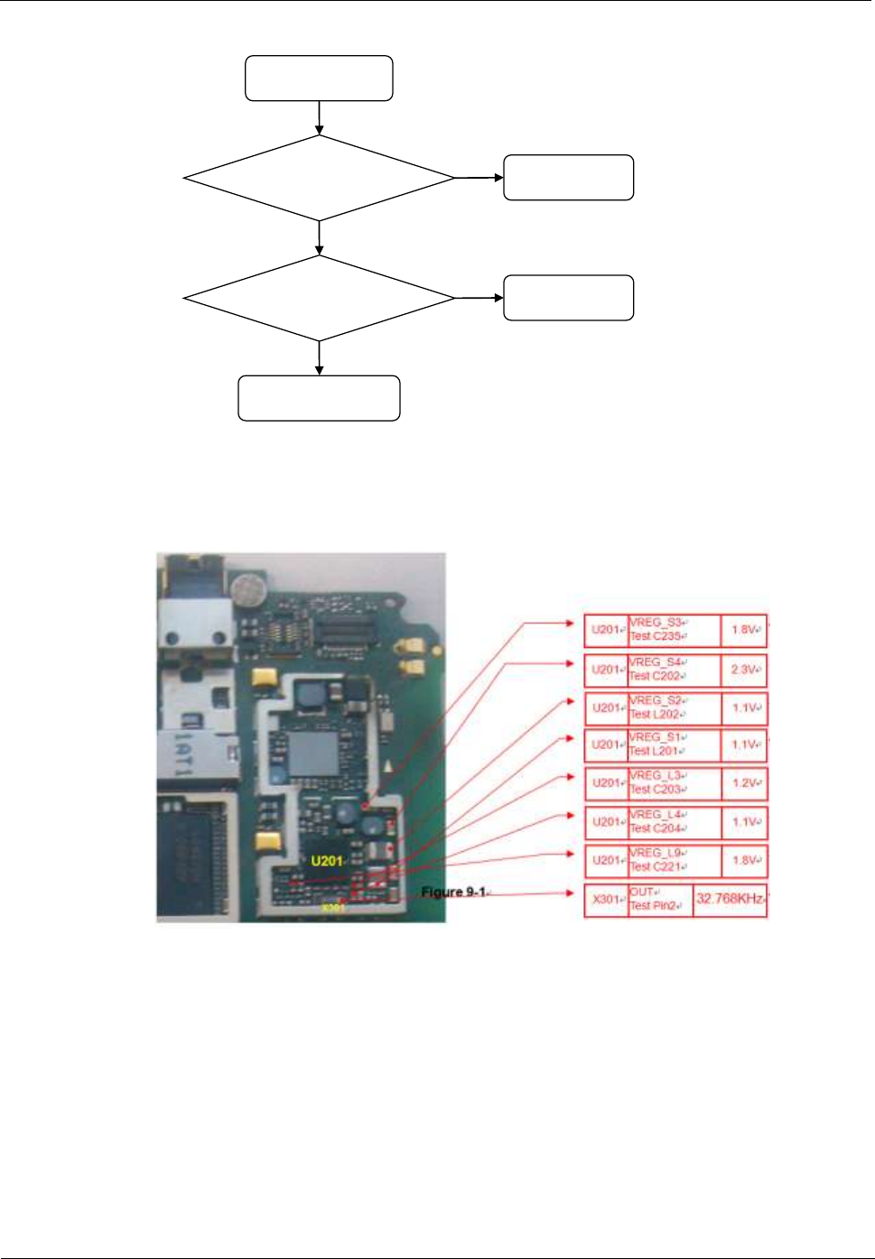
To troubleshoot the power-on failure, firstly check whether the I/O connector (battery
connector) is damaged. If the I/O connector (battery connector) is not damaged, use a DC
regulated power supply to supply power to the phone, and test the phone's current.
The power-on failure may be caused by any of the following conditions:
- No current
U8655
Maintenance Manual
9 Principles and Failure Analysis
Issue 1.0 (2012-02-23)
Huawei Proprietary and Confidential
Copyright © Huawei Technologies Co., Ltd.
27
Replace J902
N
Power-on failure:
no current
Is the battery
connector J902
normal?
Replace Q201
N
Is Q201 normal?
Y
Re-solder or replace
U201
Y
- Weak current
U8655
Maintenance Manual
9 Principles and Failure Analysis
Issue 1.0 (2012-02-23)
Huawei Proprietary and Confidential
Copyright © Huawei Technologies Co., Ltd.
28
YY
Reinstall the phone's
firmware. Is the problem
solved
NN
NN
NN
YY
Powe-on failure:
weak current
End
Is U201'output
Voltage normal
YY
Does X301 have
32.768 kHz output?
Replace U601 and reinstall
The phone's firmware. Is the
Problem solved?
YY
Replace U401
NN
Replace U201
Replace X301
End
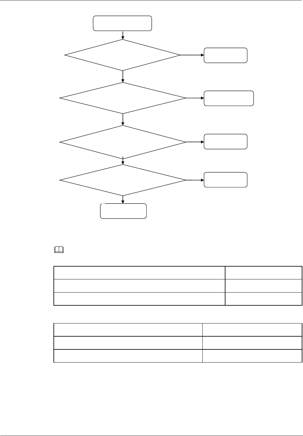
- Excessive current
Excessive current is caused by short circuits. When excessive current occurs, to prevent
damage to components, do not connect the charger to the phone. Power-on failure due to
excessive current is usually the result of short-circuited VBAT circuit.
U8655
Maintenance Manual
9 Principles and Failure Analysis
Issue 1.0 (2012-02-23)
Huawei Proprietary and Confidential
Copyright © Huawei Technologies Co., Ltd.
29
NN
Test the VBAT circuit.Is it
a short circuit
YY
NN
NN
YY
Powe-on failure:
excessive current
Check whether
VPH_PWR and
PM output are
short-circuited
Is J902 normal?
YY
Is Q201 normal?
Remove U201.Do short
circuits still exist?
YY
Replace U401
NN
Re-solder or
replace J902
Replacec Q201
Replace U201
9.2.2 Charging Management Circuits
U8655
Maintenance Manual
9 Principles and Failure Analysis
Issue 1.0 (2012-02-23)
Huawei Proprietary and Confidential
Copyright © Huawei Technologies Co., Ltd.
30
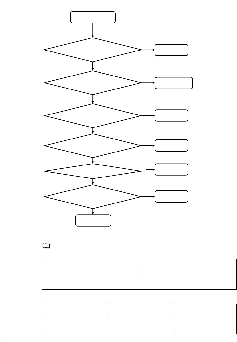
Troubleshooting Charging Failure
NN
Is the charger working
properly?
YY
YY
NN
NN
Charging failure
Replace the
charger
Is J901 poorly
soldered?
NN
Is the battery's in good
contact with the battery
connector?
Does VPH_PWR have
voltage?
YY
End
YY
Re-solder J901
Repair or replace
J902
Replace U901
Is there voltage difference
between Q201's pin 2 and
pin 3? NN Replace Q201
YY
Is the battery damaged? YY Replace the
battery
NN
9.3 RF Unit
9.3.1 RF Failure
Troubleshooting Transmission Failure
- GSM/DCS transmission failure
Before starting the following process, make sure that the USIM card and the antenna are well
connected.
U8655
Maintenance Manual
9 Principles and Failure Analysis
Issue 1.0 (2012-02-23)
Huawei Proprietary and Confidential
Copyright © Huawei Technologies Co., Ltd.
31
GSM/DCS transmission
failure
When the RF cable is not
inserted, are U3201's pin
1 and pin 2 connected? Check U3201
Are U3202's control signals
normal?
Check U401
Are U3501's GSM output
and DCS output
approximately 33 dBm and
30 dBm respectively?
Check U3202 and
U401
Check U3501
Y
N
Y
Y
Y
N
N
Do U3801's pin A10 and pin
A9 have output? Check U3801
N
Y
NOTE
- The following tables describe the working status of the GSM/DCS power amplifier U3501.
GSM_PA_EN
PA
H
ON
L
OFF
GSM_PA_BAND
MODE
L
GSM850/900
H
DCS1800/1900
- H: voltage higher than 1.3 V. L: voltage lower than 0.5 V.
- WCDMA transmission failure (use W2100 as an example)
Before starting the following process, make sure that the USIM card and the antenna are well
connected.
U8655
Maintenance Manual
9 Principles and Failure Analysis
Issue 1.0 (2012-02-23)
Huawei Proprietary and Confidential
Copyright © Huawei Technologies Co., Ltd.
32
W2100 transmission
failure
When the RF cable is not
inserted, are U3201's pin 1
and pin 2 connected? Check U3201
Are U3202's control signals
normal?
Check U401
Is the insertion loss
between U3304's pin 1 and
pin 3 approximately 1.1–1.4
dB?
Check U3202 and
U401
Check U3304
Y
N
Y
Y
Y
N
N
Is U3301's output 24 dB? Check U3301
N
Y
Y
Y
Is the insertion loss
between U3302's pin 2 and
pin 9 approximately 0.6 dB? Check U3302
N
Check U3801
N
Does U3801's pin A7 have
output?
NOTE
- The following tables describe the working status of the WCDMA power amplifier.
PA_ON
PA
H
ON
L
OFF
PA_R
PA_R1
MODE
L
L
HI Power
L
H
MI Power
U8655
Maintenance Manual
9 Principles and Failure Analysis
Issue 1.0 (2012-02-23)
Huawei Proprietary and Confidential
Copyright © Huawei Technologies Co., Ltd.
33
H
H
LO Power
- H: 1.3–1.8 V. L: < 0.5 V.
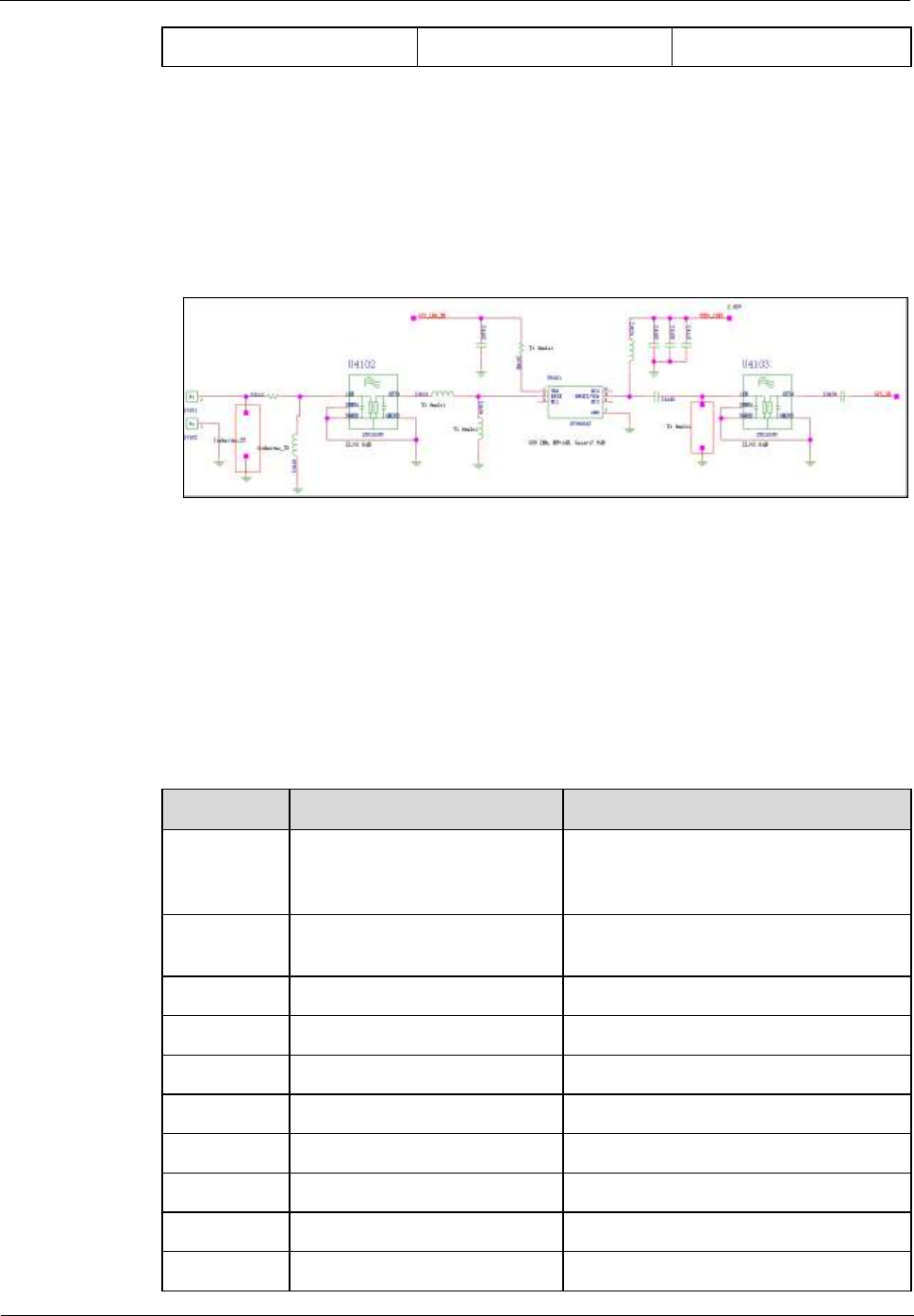
9.3.2 GPS
The GPS channel consists of filter U4102, filter U4103 and LNA U4101. GPS signals are sent
to the RTR6285A's input interface after going through the filters and LNA. The following
figure shows the circuit.
9.3.3 Wi-Fi/Bluetooth/FM Module
The U8655N uses a Wi-Fi/Bluetooth/FM 3-in-1 module (Broadcom's BCM4330).
The Bluetooth and Wi-Fi functions share one antenna and one SP3T RF switch.
The MSM7225A provides PCM and UART interfaces that are directly connected with the
Bluetooth module's PCM and UART signal output. The following table describes the signals'
definitions.
MSM7225A
Signal
Definition
GPIO_44
UART1_CTS_N
The "ready to receive" signal from the
host (the MSM7225A) to the slave (the
BCM4330).
GPIO_43
UART1_RFR_N
The "clear to send" signal sent from the
slave to the host.
GPIO_46
UART1_TX
Transmission signal
GPIO_45
UART1_RX
Reception signal
GPIO_69
AUX_PCM_DIN
PCM input
GPIO_68
AUX_PCM_DOUT
PCM output
GPIO_70
AUX_PCM_SYNC
PCM synchronization
GPIO_71
AUX_PCM_CLK
PCM clock
GPIO_107
MSM_WAKES_BT
Waking up the host
GPIO_83
BT_WAKES_MSM
Waking up the Bluetooth
U8655
Maintenance Manual
9 Principles and Failure Analysis
Issue 1.0 (2012-02-23)
Huawei Proprietary and Confidential
Copyright © Huawei Technologies Co., Ltd.
34
The MSM7225A provides SDIO3 interfaces that are directly connected with the Wi-Fi
module's SDIO signal output. The following table describes the signals' definitions.
MSM7225A
Signal
Function
GPIO_64
SDC2_DATA3
Data
GPIO_65
SDC2_DATA2
GPIO_66
SDC2_DATA1
GPIO_67
SDC2_DATA0
GPIO_62
SDC2_CLK
Clock
GPIO_63
SDC2_CMD
Control signal
The PM8029 provides audio input interfaces that are directly connected with the FM module's
left and right channels. The following table describes the signals' definitions.
BCM4330
Network
MSM7225A
Description
FM_RXP
FM_ANT
FM antenna (headset)
FM_RXN
-
-
-
FM_VDD2P5
SR_AVDD2P5
-
FM_AOUT1
FM_OUT_L
PM8029
LINE_IN_LP
FM OUTPUT
FM_AOUT2
FM_OUT_R
PM8029
LINE_IN_RM
FM OUTPUT
9.4 Peripheral Circuits
9.4.1 Display
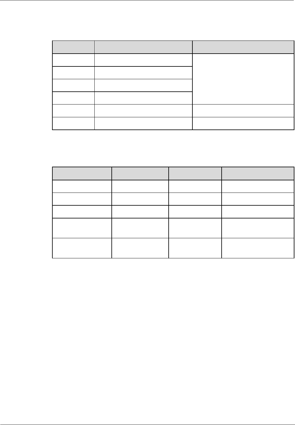
The MSM7225A uses MIPI interfaces to send instructions and data to the LCD. The
U8655N's LCD uses MIPI interfaces, supporting a 60 Hz refresh rate, and requiring only one
pair of differential clock signals and one pair of differential signals. The LCD also supports
frame synchronization, using the MDP_VSYNC signals (GPIO_097) as data transmission
synchronization signals to avoid screen tearing.
- Resolution: HVGA (480 x 320 pixels)
- Color: 256K colors
The following figure shows the connections between the MSM7225A and the LCD.
U8655
Maintenance Manual
9 Principles and Failure Analysis
Issue 1.0 (2012-02-23)
Huawei Proprietary and Confidential
Copyright © Huawei Technologies Co., Ltd.
35
The following table describes the signal definitions.
Category
Description
Name in the Circuit
Network
MSM7225A GPIO/PM8029
MPP
Power supply
Digital power supply
input
VREG_S3
VREG_S3 (PM8029)
Analog power input
VREG_L12_2P85
VREG_L12_2P85 (PM8029)
Data
MIPI data
MIPI_DSI_LANE1_P
MIPI_DSI_LANE1_P
MIPI data
MIPI_DSI_LANE1_N
MIPI_DSI_LANE1_N
Synchronization
signal
Frame synchronization
clock
MDP_VSYNC_P
GPIO97
Clock signal
MIPI clock
MIPI_DSI_CLK_P
MIPI_DSI_CLK_P
MIPI clock
MIPI_DSI_CLK_N
MIPI_DSI_CLK_N
Control signal
Reset signal
LCD_RESET_N
GPIO129
Identification
signal
LCD model identification
LCD_ID0
GPIO9 (PM8029)
LCD model identification
LCD_ID1
GPIO10 (PM8029)
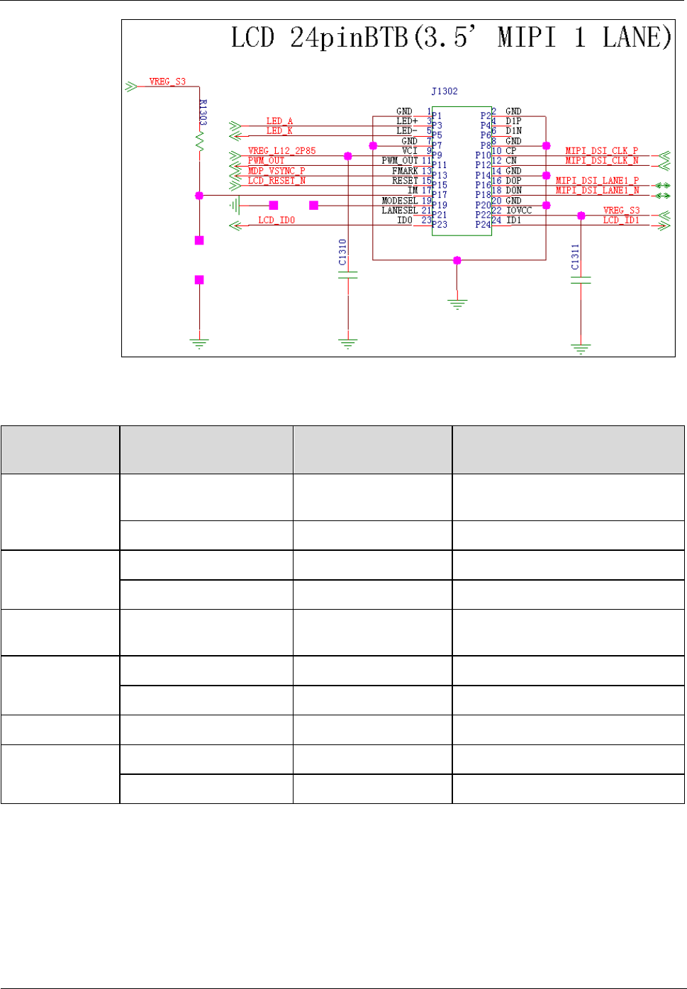
U8655N's LCD backlight control:
The U8655N uses a 3.5-inch LCD whose backlight is provided by six LEDs connected in
series. The backlight LEDs are controlled by the backlight driver chip TPS61160A. The
ground resistance of the driver chip pin FB is set to 10 Ω, providing up to 20 mA current to
the LEDs (duty:100%). The backlight brightness (driver output current) is controlled by the
PWM signal.
U8655
Maintenance Manual
9 Principles and Failure Analysis
Issue 1.0 (2012-02-23)
Huawei Proprietary and Confidential
Copyright © Huawei Technologies Co., Ltd.
36
Backlight
signals
The anode of the
backlight LED
LED_A
The anode of the backlight
LED
The cathode of the
backlight LED
LED_K
The cathode of the backlight
LED
Brightness control
signals from the LCD
PWM_OUT
Reserved
Brightness control
signals from the
phone's main chip
LCD_BL_PWM
GPIO1 (PM8029)
U8655
Maintenance Manual
9 Principles and Failure Analysis
Issue 1.0 (2012-02-23)
Huawei Proprietary and Confidential
Copyright © Huawei Technologies Co., Ltd.
37
Troubling Display Failure
LCD fails to display
Return the phone
to the factory
Check whether J1302 is
snapped in place. If it is not
in place, snap it again. Is the
problem solved?
End
Y
N
Reinstall the phone's
firmware. Is the problem
solved?
End
Y
N
Replace the LCD. Is the
problem solved? End
Y
N
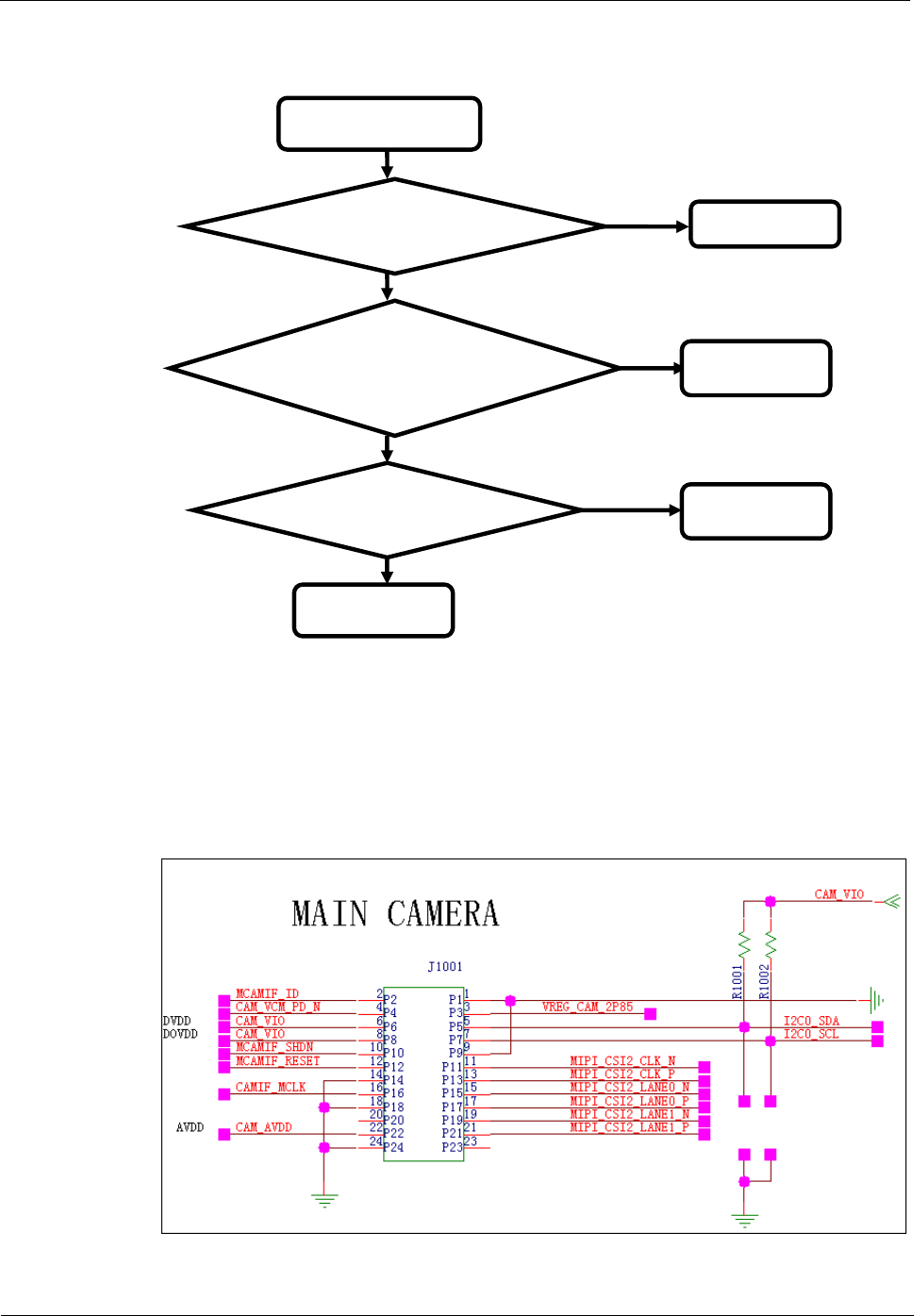
9.4.2 Camera
The U8655N uses a 3.2-megapixel full-frame camera.
The 3.2-megapixel full-frame camera uses a 24-pin BTB connector and is controlled by the
I2C bus. The data is transmitted in MIPI mode.
U8655
Maintenance Manual
9 Principles and Failure Analysis
Issue 1.0 (2012-02-23)
Huawei Proprietary and Confidential
Copyright © Huawei Technologies Co., Ltd.
38
Signal Name
Pin
Voltage
Description
CAM_VIO
VREG_S3
1.8
Controlled by the power
supply switch.
CAM_VIO
VREG_S3
1.8
Controlled by the power
supply switch.
VREG_CAM_2P85
VREG_L17(PM8029)
2.85
Power supply to the
camera autofocus motor
CAM_AVDD
VREG_L17(PM8029)
2.85
CAMIF_MCLK
GPIO_015(MSM7225A)
1.8
Camera reference clock
MCAMIF_SHDN
GPIO_119(MSM7225A)
1.8
Camera shutdown signal
CAM_VCM_PD_N
GPIO_07(MSM7225A)
1.8
Camera autofocus motor
control signal
I2C0_SCL
GPIO_060(MSM7225A)
1.8
I2C control signal
I2C0_SDA
GPIO_061(MSM7225A)
1.8
MCAMIF_RESET
GPIO_049(MSM7225A)
1.8
Reset signal
MCAMIF_ID
GPIO_9(MSM7225A)
1.8
Module supplier
identification
MIPI_CSI2_CLK_P
MIPI_CSI2_CLK_P
MIPI clock
MIPI_CSI2_CLK_N
MIPI_CSI2_CLK_N
MIPI clock
MIPI_CSI2_LANE1_P
MIPI_CSI2_LANE1_P
Data communication
signal
MIPI_CSI2_LANE1_N
MIPI_CSI2_LANE1_N
Data communication
signal
MIPI_CSI2_LANE0_P
MIPI_CSI2_LANE0_P
Data communication
signal
MIPI_CSI2_LANE0_N
MIPI_CSI2_LANE0_N
Data communication
signal
NOTE
The camera interface circuit is designed for compatibility with multiple types of cameras. The U8655N
uses a 3.2-megapixel full-frame camera, so the CAM_VCM_PD_N and VREG_CAM_2P85 lines are
not used.
U8655
Maintenance Manual
9 Principles and Failure Analysis
Issue 1.0 (2012-02-23)
Huawei Proprietary and Confidential
Copyright © Huawei Technologies Co., Ltd.
39
Troubleshooting Camera Failure
Failure to take photos or
record video using the
camera
Replace the
camera. Is the
problem solved? End
Is J1001 poorly soldered or
are its contacts defective?
Return the phone
to the factory
Re-solder or replace
J1001
Y
N
Y
Reinstall the phone's
firmware. Is the
problem solved?
End
Y
N
N
9.4.3 USB
U8655
Maintenance Manual
9 Principles and Failure Analysis
Issue 1.0 (2012-02-23)
Huawei Proprietary and Confidential
Copyright © Huawei Technologies Co., Ltd.
40
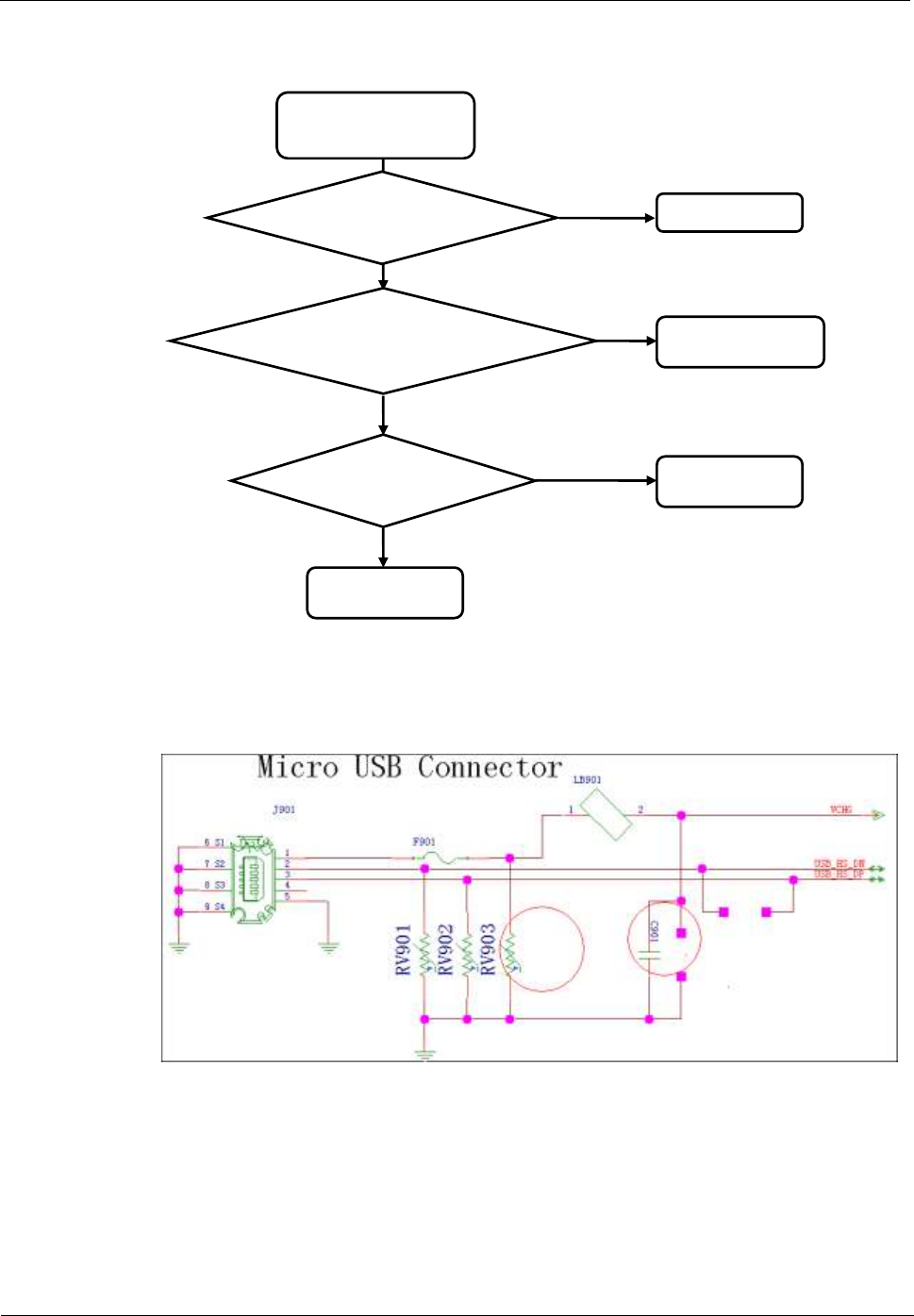
Troubleshooting USB Connection Failure
USB connection failure
Reinstall the
phone's firmware.
Is the problem
solved?
End
Is the 5-pin mini USB
connector poorly soldered?
Return the phone
to the factory
Re-solder the USB
connector
Y
N
Y
Use a normal USB
cable. Is the problem
solved? End
Y
N
N
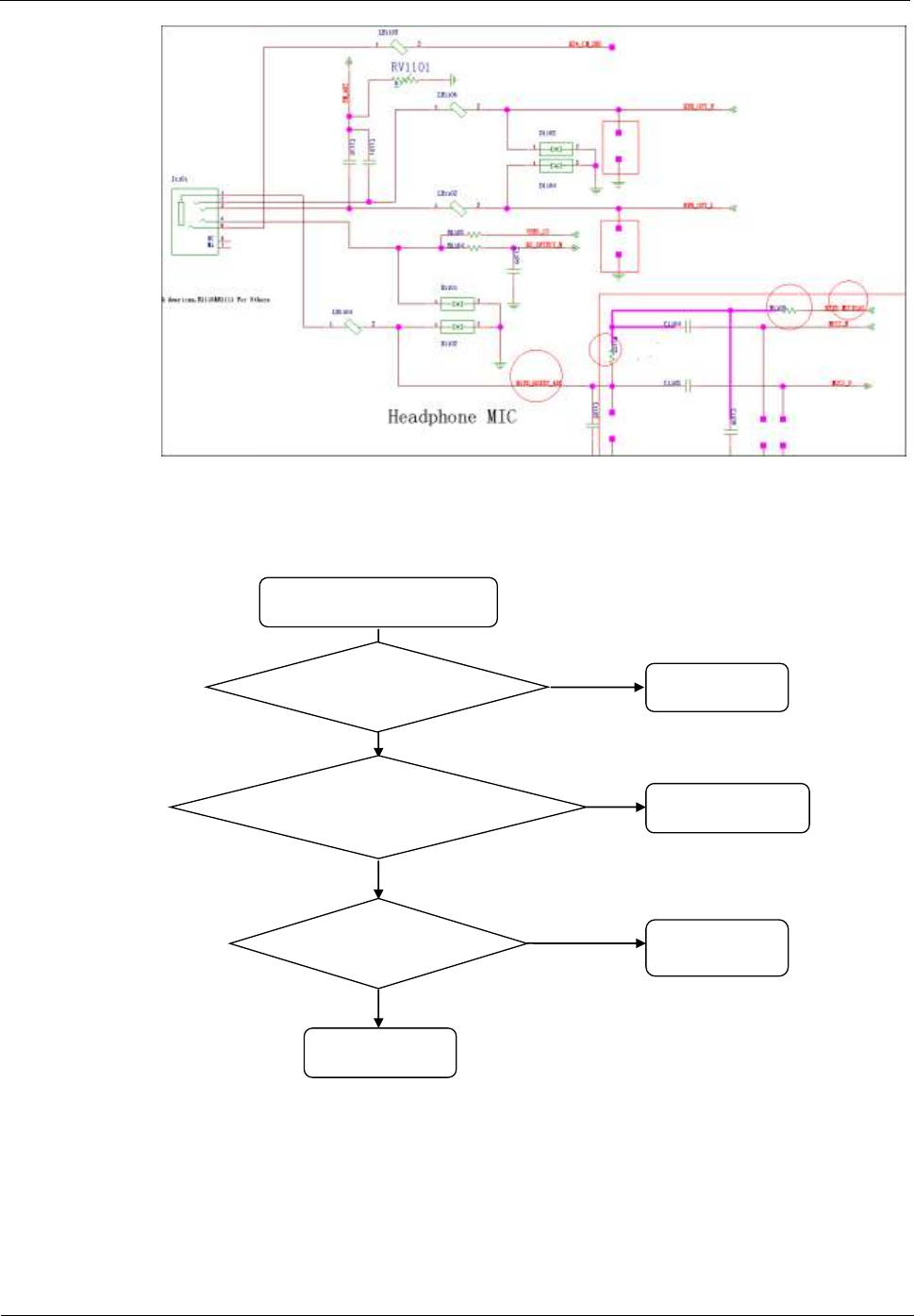
9.4.4 Headset Jack
The headset jack is a 3.5-mm headset jack. When the headset jack has no headset inserted, the
headset jack's pin 3 and pin 4 are open, and the headset detection voltage is at high level.
After a headset is inserted, pin 3 and pin 4 are closed, and the headset detection voltage is at
low level, indicating the insertion of a headset. The HS_DETECT (GPIO86) pin is used to
detect the headset insertion.
The HSED_MICBIAS (PM8029/HSED_BIAS1) supplies power to the headset microphone.
The HSED_HSKEY_ADC (PM8029 MPP5) is used to detect the headset button press.
NOTE
The U8655N supports only LRGM headsets, and does not support LRMG headsets.
U8655
Maintenance Manual
9 Principles and Failure Analysis
Issue 1.0 (2012-02-23)
Huawei Proprietary and Confidential
Copyright © Huawei Technologies Co., Ltd.
41
- No sound comes from the headset during a call
After a call is established, no
sound can be heard from the
headset
Is a headset icon
displayed on the
screen?
Replace the
headset jack
Replace the headset. Is the
problem solved?
Return the phone
to the factory
End
Y
Y
N
Is the in-call volume
set to a normal level? End
N
N
Y
- The headset button cannot be used to answer a call
U8655
Maintenance Manual
9 Principles and Failure Analysis
Issue 1.0 (2012-02-23)
Huawei Proprietary and Confidential
Copyright © Huawei Technologies Co., Ltd.
42
The headset button cannot be
used to answer a call
Is the voltage on J1101's
pin 4 at low level after the
headset is inserted?
Return the phone
to the factory
Check that J1101 is
properly soldered.
N
Replace the headset.
Is the problem solv ed? End
Y
Y
N
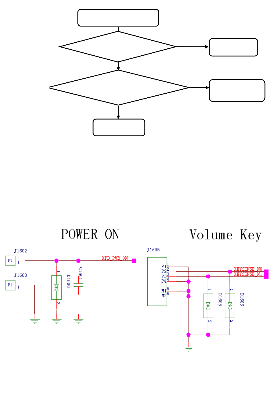
9.4.5 Keys
The U8655N has six keys, three of which are the Menu, Home and Back keys on the
touchscreen panel.
The MSM7225A's GPIO_42 and GPIO_41 pins are connected to the volume up and down
keys. The side key FPC is connected to the PCBA via the ZIF connector J1605.
The Power key press is detected by the PM8029's KPD_PWR_ON pin. The Power key FPC is
connected to the PCBA using press-fit contacts.
U8655
Maintenance Manual
9 Principles and Failure Analysis
Issue 1.0 (2012-02-23)
Huawei Proprietary and Confidential
Copyright © Huawei Technologies Co., Ltd.
43
Troubleshooting Key Failure
Key failure
Are the FPC and ZIF
connector connected
properly? Re-connect them
Return the phone
to the factory
Y
N
Is the keypad on the
FPC in good contact
with the dome sheet?
Clean the
keypad and the
dome sheet
N
Y
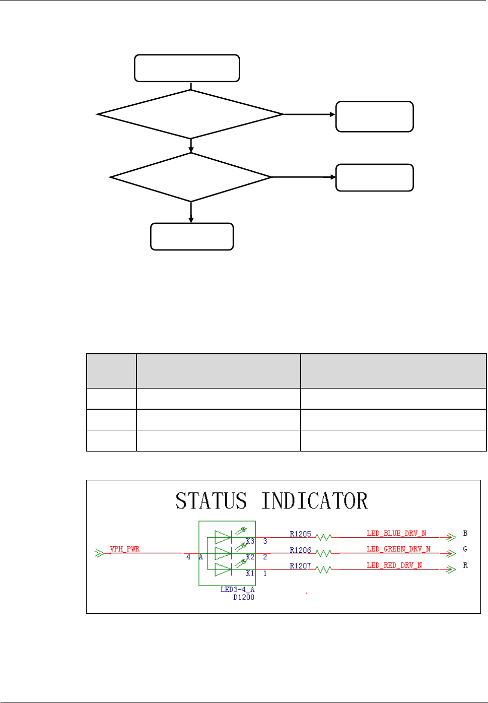
9.4.6 Status Indicator and Touch Key Backlight Circuits
The U8655N's status indicator (tricolor indicator) provides red, green and blue light sources
that are driven by the PM8029's three LED drivers.
Light
Source
Driver Pin (PM8029)
Description
Red
LED_RED_DRV_N (MPP3)
Adjusted using electric current
Green
LED_GREEN_DRV_N (MPP5)
Adjusted using electric current
Blue
LED_BLUE_DRV_N (MPP8)
Adjusted using electric current
The KYPD_DRV_N (PM8029) is used to adjust the brightness of the keypad's backlight, and
VPH_PWR is used to supply power to the backlight LEDs. The keypad backlight is provided
by two white LEDs. The light from the LEDs are transmitted to the key area using a light
guide film.
U8655
Maintenance Manual
9 Principles and Failure Analysis
Issue 1.0 (2012-02-23)
Huawei Proprietary and Confidential
Copyright © Huawei Technologies Co., Ltd.
44
Keypad Backlight Driver
VPH_PWR
Power supply
Backlight power supply
KPD_DRV_N
Backlight driver pin
When this pin's voltage is at low
level, the two backlight LEDs
turns on.
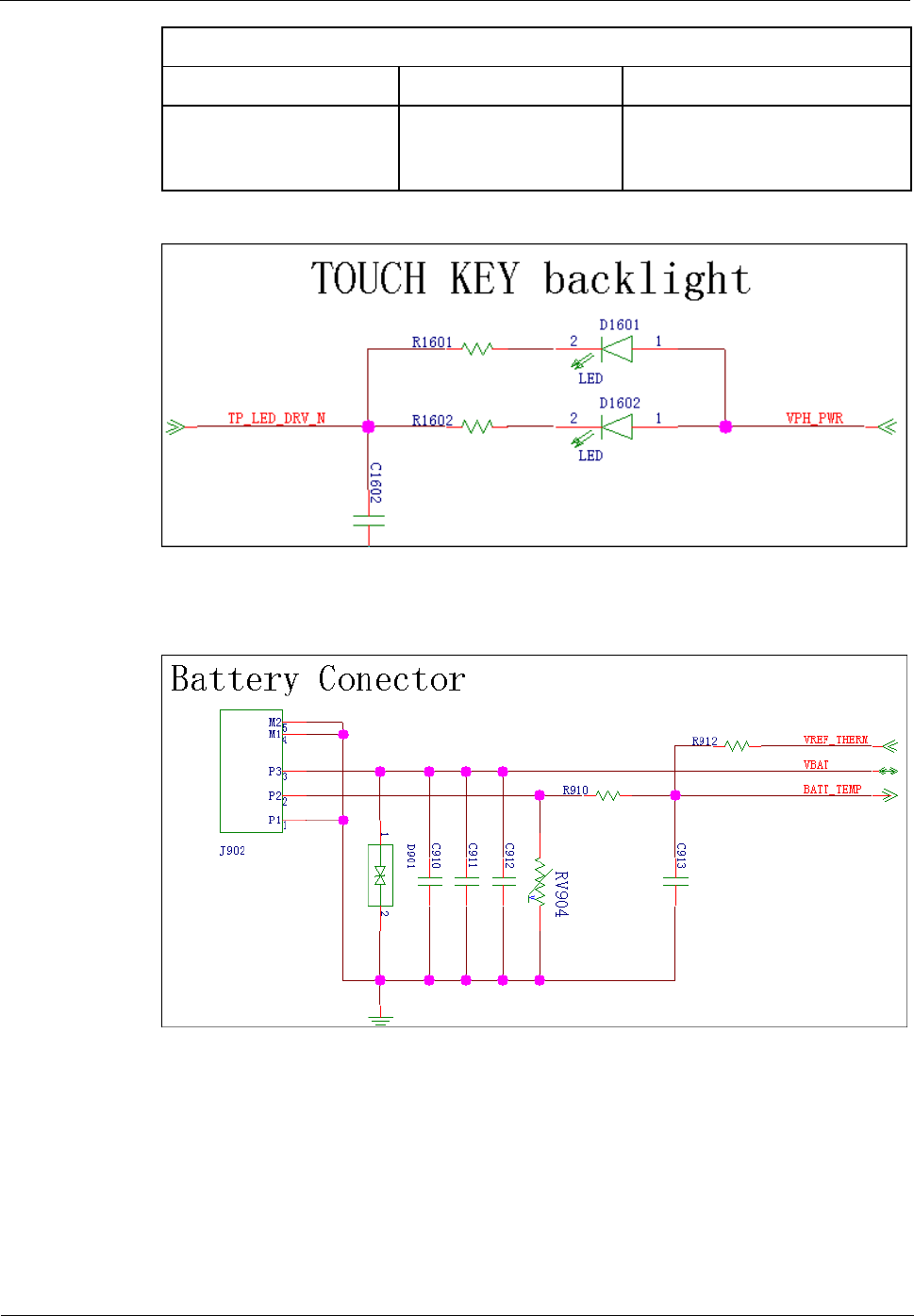
9.4.7 Battery Connector
U8655
Maintenance Manual
9 Principles and Failure Analysis
Issue 1.0 (2012-02-23)
Huawei Proprietary and Confidential
Copyright © Huawei Technologies Co., Ltd.
45
9.4.8 Accelerometer
Component
Pin
Network
MSM7225A Pin
Description
SCL
I2C1_SCL
GPIO_131
I2C bus
SDA
I2C1_SDA
GPIO_132
INT1
MEMS_INT1
GPIO_28
Accelerometer interrupt
signal
INT2
MEMS_INT2
GPIO_111
Accelerometer interrupt
signal (sleep)
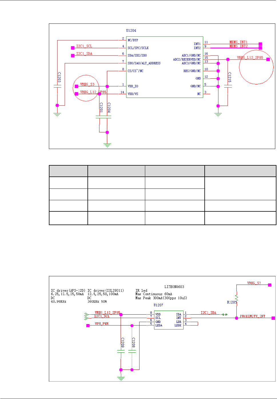
9.4.9 Proximity and Illuminance Sensor
The U8655N has a proximity and illuminance sensor. The following figure shows the sensor
circuit.
U8655
Maintenance Manual
9 Principles and Failure Analysis
Issue 1.0 (2012-02-23)
Huawei Proprietary and Confidential
Copyright © Huawei Technologies Co., Ltd.
46
Component Pin
Network
MSM7225A-0 Pin
Description
SCL
I2C1_SCL
GPIO_131
I2C bus
SDA
I2C1_SDA
GPIO_132
INT
PRO_INT
GPIO_17
3-in-1 interrupt signal
Functions
- Detect the intensity of environmental light.
- Detect the proximity of objects.
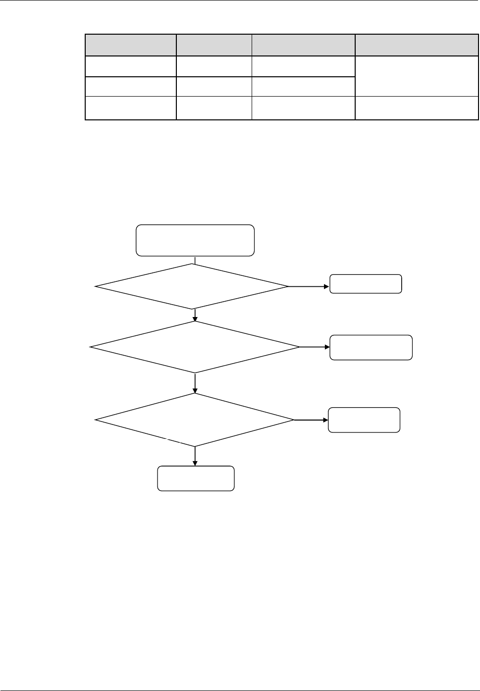
The phone's display does not
turn off when near the user's
ear during a call
Is U1207 poorly soldered
or dirty? Re-solder, clean
or replace U1207
Reinstall the phone's
firmware. Is the problem
solved?
Return the phone
to the factory
End
Y
N
Y
Is the touchscreen panel's
illuminance sensor hole dirty
or blocked?
Clean the hole
Y
N
N
U8655
Maintenance Manual
9 Principles and Failure Analysis
Issue 1.0 (2012-02-23)
Huawei Proprietary and Confidential
Copyright © Huawei Technologies Co., Ltd.
47
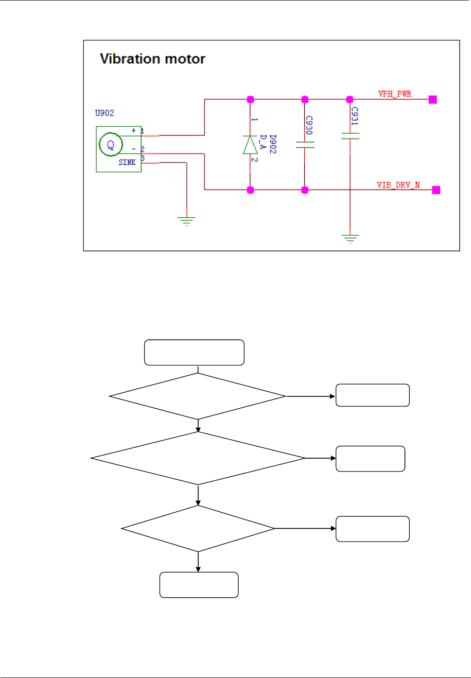
9.4.10 Vibration Motor
The motor driver current is controlled by PM VIB_DRV_N.
Troubleshooting Vibration Failure
Vibration failure
Is the voltage on
VIB_DRV_N equal to
the battery voltage? Replace D902
Replace the motor. Is the
problem solved?
Return the phone
to the factory
End
Y
N
Y
Reinstall the phone's
firmware. Is the
problem solved?
End
Y
N
N
U8655
Maintenance Manual
9 Principles and Failure Analysis
Issue 1.0 (2012-02-23)
Huawei Proprietary and Confidential
Copyright © Huawei Technologies Co., Ltd.
48
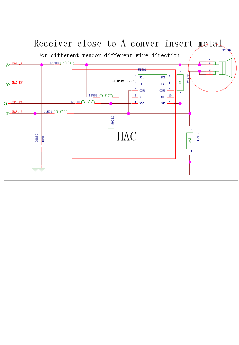
9.4.11 Receiver
The receiver receives differential earphone output from the MSM chip. The following figure
shows the circuit.
The MSM chip's EARI output signal is connected to the receiver. Bypass capacitors are added
to the signal traces. The circuit shown in the previous figure is designed for compatibility.
L1508, L1510 and U1501 are reserved for the HAC function and are not soldered on the
U8655N. D1503 and D1504 are the ESD protection components on the receiver.
U8655
Maintenance Manual
9 Principles and Failure Analysis
Issue 1.0 (2012-02-23)
Huawei Proprietary and Confidential
Copyright © Huawei Technologies Co., Ltd.
49
Troubleshooting the Failure that No Sound Can Be Heard During a Call
No sound is heard
during a call
Replace the
receiver. Is the
problem solved? End
Does the phone mistakenly
detect the insertion of a
headset?
Return the phone
to the factory
Replace the
headset connector
Y
N
Y
Is the in-call volume
set to a normal level? End
N
N
Y
U8655
Maintenance Manual
9 Principles and Failure Analysis
Issue 1.0 (2012-02-23)
Huawei Proprietary and Confidential
Copyright © Huawei Technologies Co., Ltd.
50
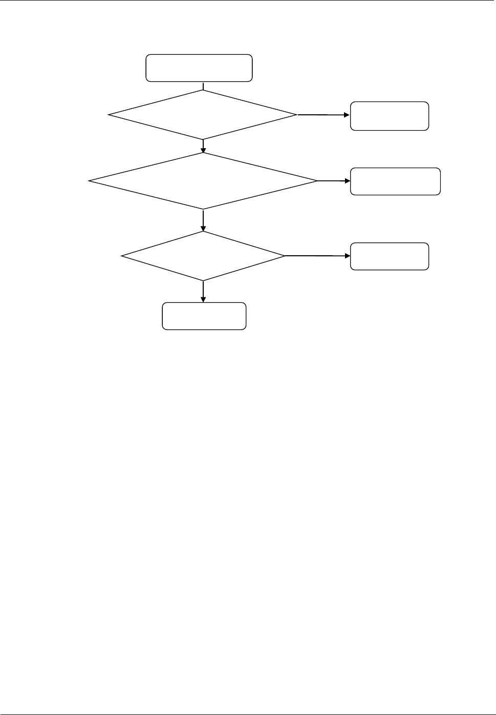
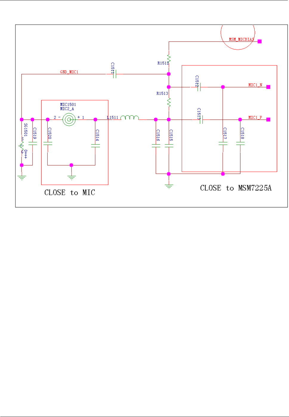
9.4.12 Microphone
U8655
Maintenance Manual
9 Principles and Failure Analysis
Issue 1.0 (2012-02-23)
Huawei Proprietary and Confidential
Copyright © Huawei Technologies Co., Ltd.
51
Troubleshooting the Failure that No Sound Can Be Heard by the Other Party
During a Call
No sound can be heard by
the other party during a call
Replace the
microphone. Is the
problem solved? End
Is the MIC_BIAS voltage
equal to 1.8 V?
Return the phone
to the factory
Check U201
N
N
Y
Reinstall the phone's
firmware. Is the
problem solved? End
Y
Y
N
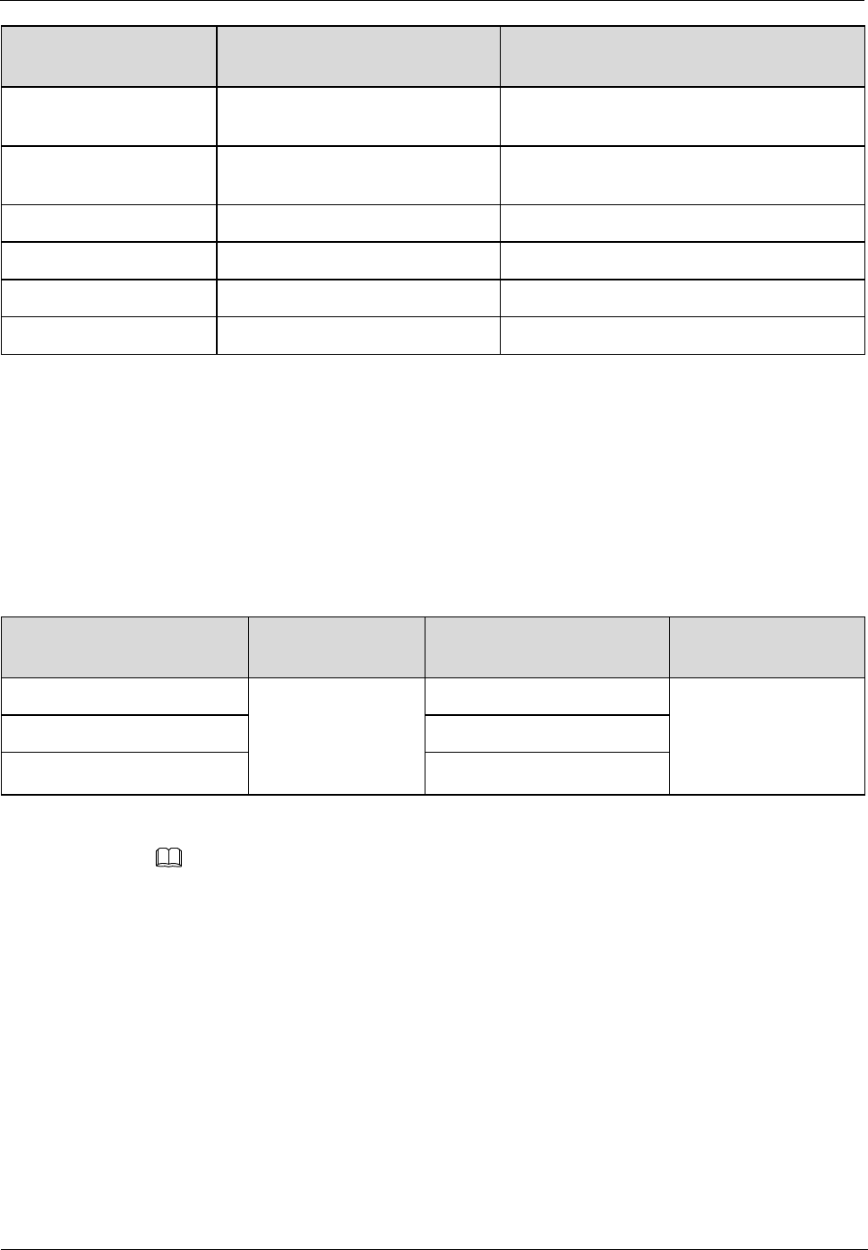
9.4.13 Touchscreen Panel
The U8655N's 3.5-inch capacitive touchscreen panel has a touch key area containing three
touch keys. The backlight LEDs for the three touch keys are located on the PCBA. A light
guide film is used to guide light from the LEDs to the touch key area.
The following table describes the interfaces between the touchscreen panel, MSM7225A and
PM8029.
U8655
Maintenance Manual
9 Principles and Failure Analysis
Issue 1.0 (2012-02-23)
Huawei Proprietary and Confidential
Copyright © Huawei Technologies Co., Ltd.
52
Touchscreen Panel
Interface
Pin
Description
VDD_2V8_TP
VREG_L12_2P85 (PM8029)
Touchscreen panel analog power supply,
2.85 V
VREG_S3
VREG_S3 (PM8029)
Touchscreen panel digital power supply and
I/O connector power supply, 1.8 V
TOUCH_INT
GPIO_82 (MSM7225A)
Touchscreen panel interrupt signal
I2C1_SCL
GPIO_131 (MSM7225A)
Touchscreen panel's I2C clock
I2C1_SDA
GPIO_132 (MSM7225A)
Touchscreen panel's I2C data
TOUCH_RST_N
GPIO_96 (MSM7225A)
Touchscreen panel reset signal
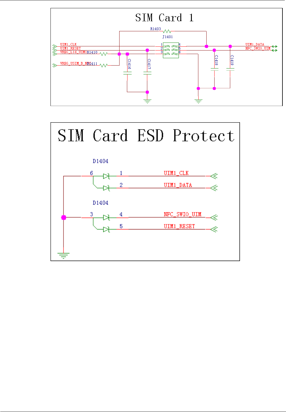
9.4.14 SIM Card
The MSM7225A is not compatible with the SIM card interface. The PM8029's MPP pins are
used to convert voltage levels of the signals for communication between the MSM7225A and
the SIM card.
The voltage of VREG_L16_UIM1 can be set to 1.5–3.05 V. The USIM interface's operating
voltage is usually 1.8 V or 3.0 V. The following table describes the voltage level conversion
interface of the PM8029.
Signal for Interfacing
with the MSM
Voltage Level
Signal for Interfacing
with the USIM Card
Voltage Level
VREG_S3
UIM1_RESET
VREG_L16_UIM1
(configured by the
phone's firmware)
UIM1_MSM_CLK
UIM1_CLK
UIM1_MSM_DATA
UIM1_DATA
NOTE
Considering that SIM card operations are frequent, transient-voltage-suppression (TVS) diodes are
added to the circuit to provide ESD and surge protection.
USIM card circuit
U8655
Maintenance Manual
9 Principles and Failure Analysis
Issue 1.0 (2012-02-23)
Huawei Proprietary and Confidential
Copyright © Huawei Technologies Co., Ltd.
53
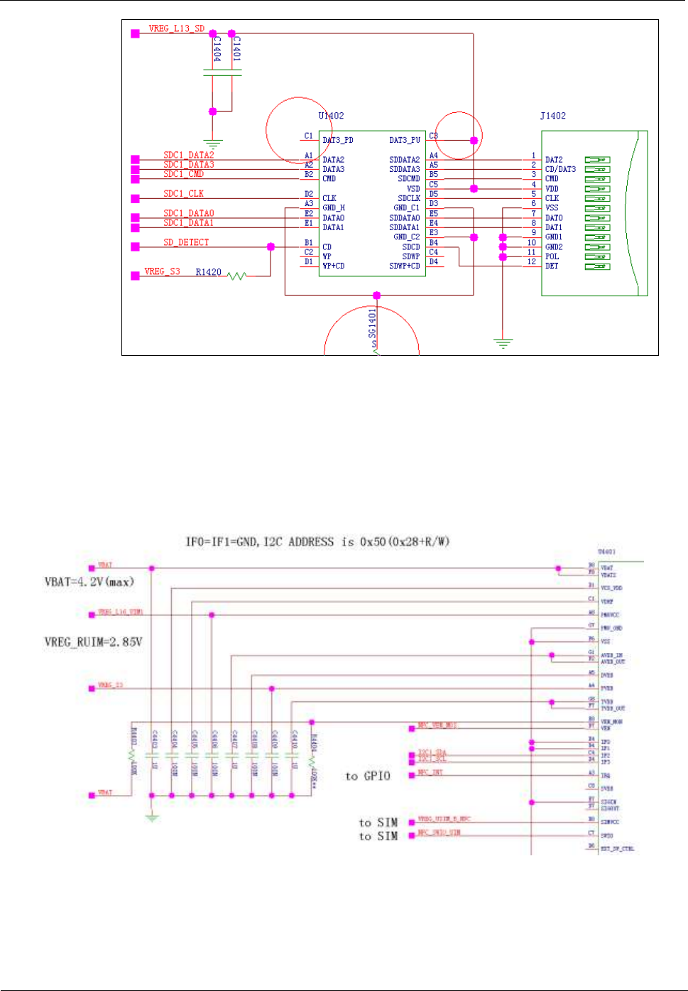
9.4.15 microSD Card
The microSD card connector's SD_DETECT pin is used to detect the insertion of a microSD
card. When a microSD card is inserted, the pin is grounded and its voltage is at low level.
When no microSD is inserted, its voltage is at high level. The U1402 is an EMI and ESD
protection component for the microSD card.
The following figure shows the circuit.
U8655
Maintenance Manual
9 Principles and Failure Analysis
Issue 1.0 (2012-02-23)
Huawei Proprietary and Confidential
Copyright © Huawei Technologies Co., Ltd.
54
9.4.16 NFC
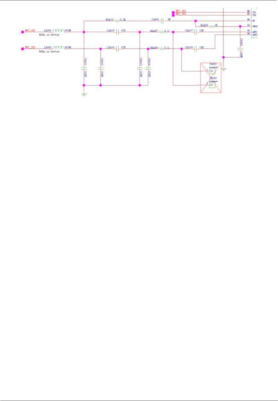
U8655N supports NFC module function, and uses NFC control chip of NXP to receive and
process signal. when use NFC function normally, the battery cover must be covered because
of built-in antenna. the signal NFC_VEN_MOS which is the reset signal of NFC module is
controlled by NFC_VEN signal, this module uses a clock of 19.2MHz to ensure module work
properly.
U8655
Maintenance Manual
9 Principles and Failure Analysis
Issue 1.0 (2012-02-23)
Huawei Proprietary and Confidential
Copyright © Huawei Technologies Co., Ltd.
55
U8655
Maintenance Manual
9 Principles and Failure Analysis
Issue 1.0 (2012-02-23)
Huawei Proprietary and Confidential
Copyright © Huawei Technologies Co., Ltd.
56
U8655
Maintenance Manual
9 Principles and Failure Analysis
Issue 1.0 (2012-02-23)
Huawei Proprietary and Confidential
Copyright © Huawei Technologies Co., Ltd.
57
Troubleshooting the Failure of NFC swiping
YY
Update the phone's software,
Is the problem solved?
NN
NN
NN
Swiping card
failure
End
Is the antenna in
good contact with
metal dome?
YY
Is power output
Voltage normal?
YY
Return to factory
Replace battery
covere with antenna
Re-solder U4401
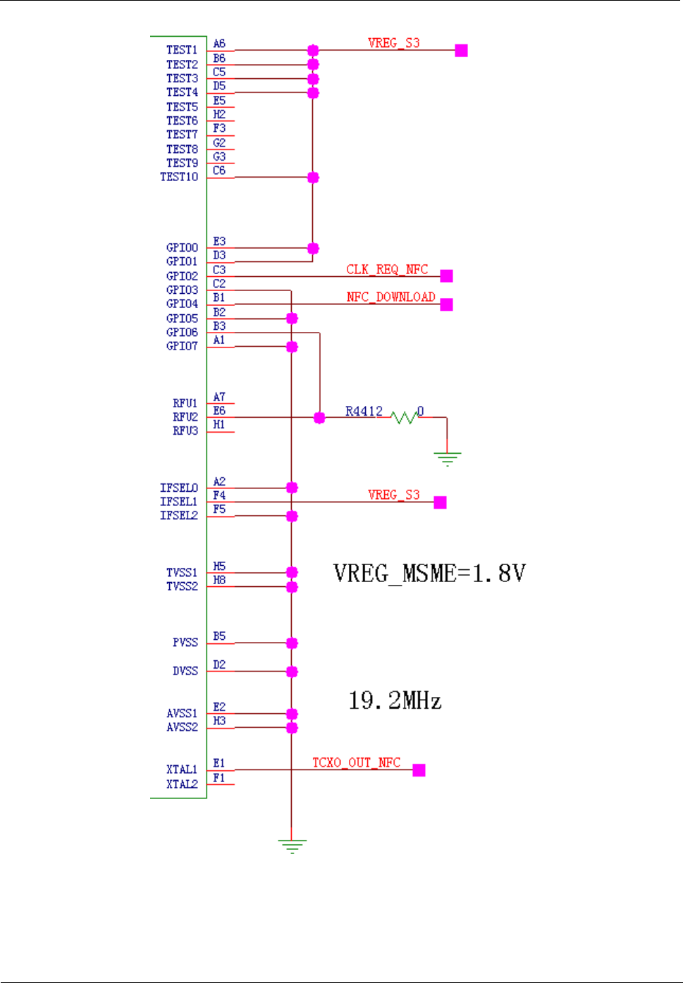
Signal name
Description
Voltage or Waveform
NFC_VEN_MOS
NFC chip reset signal
The same voltage of battery

U8655
Maintenance Manual
9 Principles and Failure Analysis
Issue 1.0 (2012-02-23)
Huawei Proprietary and Confidential
Copyright © Huawei Technologies Co., Ltd.
58
Signal name
Description
Voltage or Waveform
NFC_VEN
The reset signal from CPU
1.8V
NFC_TX1
Contactless Transmitter output1
-
NFC_TX2
Contactless Transmitter output2
-
VBAT
Battery power
Battery voltage 3.6V-4.2V
VREG_S3
power
1.8V
TCXO_OUT_NFC
Clock signal
19.2MHz
U8655
Maintenance Manual
10 Solder Points on the PCB and BGA Chip
Issue 1.0 (2012-02-23)
Huawei Proprietary and Confidential
Copyright © Huawei Technologies Co., Ltd.
59
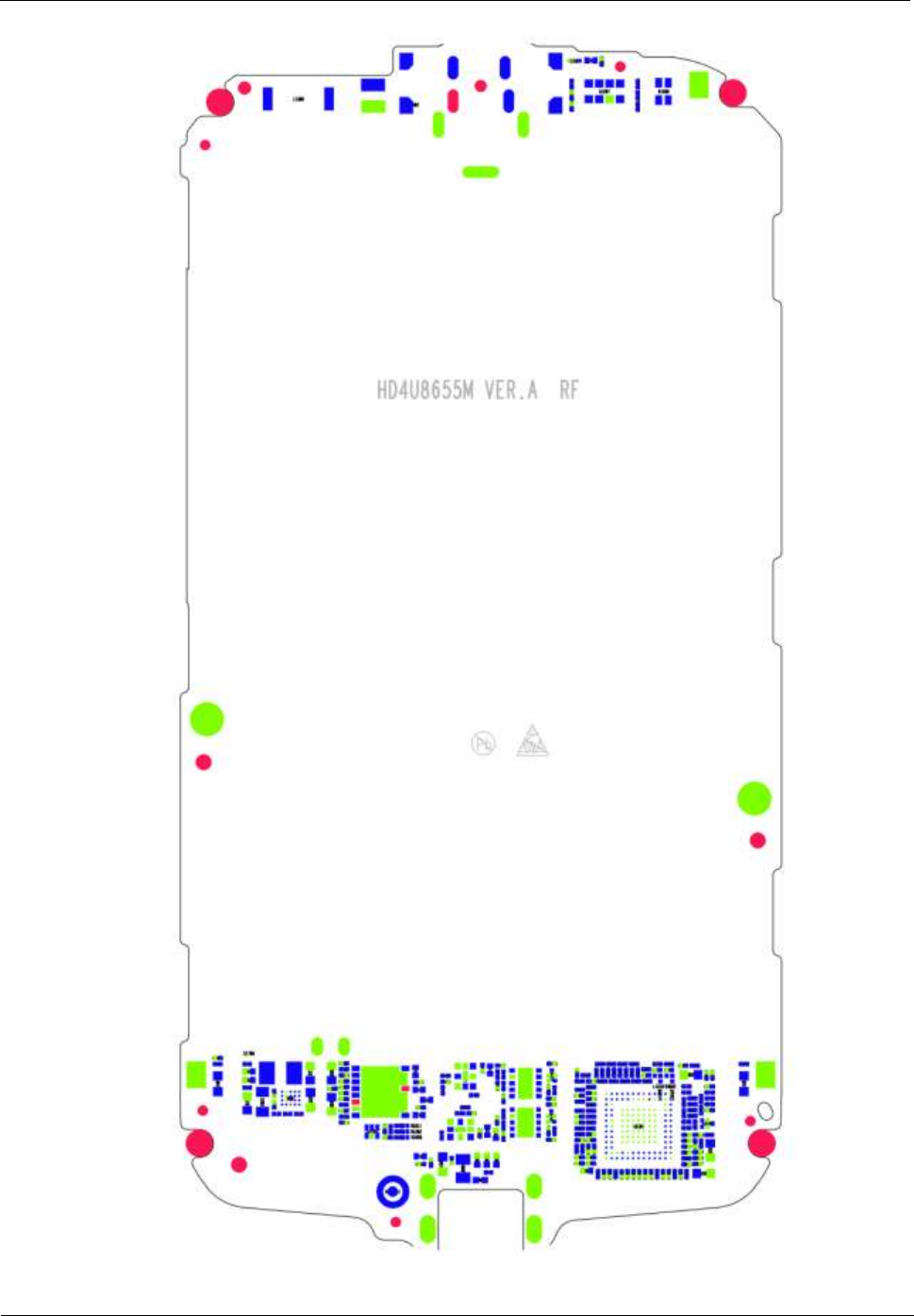
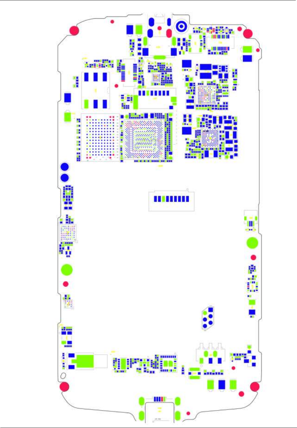
10 Solder Points on the PCB and BGA
Chip
Red (R: 255, G: 0, B: 0) : Vacant point
Green (R: 0, G: 255, B: 0) : Ground point
Blue (R: 0, G: 0, B: 255) : Solder point
Magnified views of sections:
PM section
MSM7225A+NAND MCP section
U8655
Maintenance Manual
10 Solder Points on the PCB and BGA Chip
Issue 1.0 (2012-02-23)
Huawei Proprietary and Confidential
Copyright © Huawei Technologies Co., Ltd.
60
Wi-Fi/Bluetooth/FM section
RTR8285A section
U8655
Maintenance Manual
10 Solder Points on the PCB and BGA Chip
Issue 1.0 (2012-02-23)
Huawei Proprietary and Confidential
Copyright © Huawei Technologies Co., Ltd.
61
Complete PCB view:
U8655
Maintenance Manual
10 Solder Points on the PCB and BGA Chip
Issue 1.0 (2012-02-23)
Huawei Proprietary and Confidential
Copyright © Huawei Technologies Co., Ltd.
62
U8655
Maintenance Manual
10 Solder Points on the PCB and BGA Chip
Issue 1.0 (2012-02-23)
Huawei Proprietary and Confidential
Copyright © Huawei Technologies Co., Ltd.
63
U8655
Maintenance Manual
11 Functional Tests
Issue 1.0 (2012-02-23)
Huawei Proprietary and Confidential
Copyright © Huawei Technologies Co., Ltd.
64
11 Functional Tests
11.1 MMI Test
On the Home, enter *#*#2846579#*#* to enter the MMI test mode. Press the Volume– key to
start a test. Touch the Menu key on the touchscreen panel to skip the current test and go to the
next step. Touch the Back key to return to the previous test.
NOTE
- When no battery is installed or the battery voltage is low, the phone will indicate that the battery is
low and the MMI test cannot be started.
- During a test, if you touch the Menu key on the touchscreen panel, the test will be skipped and
marked as a failed test.
No.
Category
Item
Test Method
1
SD card test
microSD card test
Automatically test the microSD card functions. If a
microSD card is found and is available, the test passes.
Otherwise, the test fails.
If this test passes, the next test automatically starts.
2
SIM card test
SIM card test
Automatically test whether the SIM card can be
recognized. If the SIM card cannot be recognized, a
message will be displayed, indicating that this test fails.
If this test passes, the next test automatically starts.
3
Battery test
Battery test
Automatically test whether the battery is in place and
whether its power is sufficient. If this test fails, a message
will be displayed.
If this test passes, the next test automatically starts.
4
Keypad test
Keys
Press or touch all the keys.
When a key is pressed or touched, the color of the
corresponding key displayed on the screen will change
(from white to blue, or from blue to white). After all keys
are tested, press the Volume– key to start the next test.
5
LCD test
White screen
The LCD displays a white screen.
Press the Volume– key to start the next test.

U8655
Maintenance Manual
11 Functional Tests
Issue 1.0 (2012-02-23)
Huawei Proprietary and Confidential
Copyright © Huawei Technologies Co., Ltd.
65
No.
Category
Item
Test Method
Black screen
The LCD displays a black screen.
Press the Volume– key to start the next test.
Red and blue bars
The LCD displays red and blue bars.
Press the Volume– key to start the next test.
6
LCD backlight
and status
indicator test
LCD backlight and
status indicator
If the LCD backlight repeatedly turns on and off, the
LCD backlight is normal. The status indicator is normal if
its color repeatedly changes in the sequence of red, green
and blue.
Press the Volume– key to start the next test.
7
Keypad LED
test
Keypad backlight LEDs
If the keypad backlight repeatedly turns on and off, the
backlight LEDs are normal.
Press the Volume– key to start the next test.
8
Camera test
Camera test
Automatically test the camera. The phone's camera is
turned on, and the LCD displays the preview. Check the
image quality visually and test the camera's response
speed to determine the camera's performance.
Press the Volume– key to start the next test.
9
Touch screen
test
Touch screen panel
There are three vertical gridlines which are composed of
a group of squares, one is in middle, the other are on
edge, Place your figure on the touch screen panel, and
slide your figure sweep each square along the gridline.
The areas near the route that your figure passes should
turn red. it will fail if the finger sweeps outside of these
squares.
Press the Volume– key to start the next test.
10
Approach test
The proximity and
illuminance sensor's
proximity detection
function
Place the light shielding plate approximately 4 mm above
the light hole. If a phone icon is displayed nearby the
portrait, the function is normal.
If this test passes, the next test automatically starts.
11
Environmental
light test
The proximity and
illuminance sensor's
function to sense
environmental light
Check whether the environmental light sensing data is
detected: Use your hand to block the light hole, the light
sensing number will decrease approximately 10 if the
illuminance sensor functions properly.
If this test passes, the next test automatically starts.
12
Vibration test
Vibration motor
The motor will vibrate intermittently.
Check whether the vibration (including the vibration
sound) is normal.
Press the Volume– key to start the next test.
13
Speaker test
Speaker test
Automatically test the speaker. (Do not insert the
headset.) If the speaker emits sound during the test, it is
normal.
Press the Volume– key to start the next test.

U8655
Maintenance Manual
11 Functional Tests
Issue 1.0 (2012-02-23)
Huawei Proprietary and Confidential
Copyright © Huawei Technologies Co., Ltd.
66
No.
Category
Item
Test Method
14
Mobile phone
mic loopback
test
Main microphone
(located near the USB
port)
Do not insert the headset. Touch the Record button.
Speak to the main microphone, and then touch the Play
button. If the main microphone is normal, you can hear
the voice recording from the receiver.
Press the Volume– key to start the next test.
15
Mobile phone
loopback test
Secondary microphone
(located above the
camera at the phone's
rear)
Do not insert the headset. Touch the Record button.
Speak to the secondary microphone, and then touch the
Play button. If the secondary microphone is normal, you
can hear the voice recording from the receiver.
Press the Volume– key to start the next test.
16
Dual MIC test
Main and secondary
microphones
Do not insert the headset. Touch the Record button.
Speak to the phone as you do during a call, and then
touch the Play button. If the main and secondary
microphones are normal, you can hear the voice
recording from the receiver.
Press the Volume– key to start the next test.
17
Mobile phone
Headset
loopback test
Headset
Insert the headset. Touch the Record button. Speak to the
headset microphone, and then touch the Play button. If
the headset is normal, you can hear the voice recording
from the headset's earphones.
Keep the headset inserted. Press the Volume– key to start
the next test.
18
FM test
FM test
The testing software will detect whether a headset is
inserted. If no headset is inserted, a message requesting a
headset to be inserted will be displayed. After a headset is
inserted, the phone will search for and play an FM
channel. Three frequencies (88 MHz, 98 MHz and 107
MHz) will be tested. The 88 MHZ frequency will be
tested first. To test the next frequency, touch Next
Channel.
Remove the headset. Press the Volume– key to start the
next test.
19
Headset Wire
control test
Headset button test
Insert the headset. The IN icon will turn green.
Press the headset button, and the round dot will become
smaller. Remove the headset, and the OUT icon will turn
green.
Press the Volume– key to start the next test.
20
Bluetooth test
Bluetooth test
Automatically test the Bluetooth functions.
During the test, the phone will search for Bluetooth
devices, and display the MAC addresses of the Bluetooth
devices that have been found. (Note: This test requires
another device with Bluetooth enabled.)
Press the Volume– key to start the next test.

U8655
Maintenance Manual
11 Functional Tests
Issue 1.0 (2012-02-23)
Huawei Proprietary and Confidential
Copyright © Huawei Technologies Co., Ltd.
67
No.
Category
Item
Test Method
21
Gravity sensor
test
Accelerometer
The LCD displays the current acceleration in the X, Y
and Z axes. Place the phone in a position where the
angles between the X, Y and Z axes are 45°. If the
acceleration in the X, Y and Z axes is equal to each other,
the phone passes this test.
If this test passes, the next test automatically starts.
22
WiFi test
Wi-Fi test
Automatically test the Wi-Fi functions.
During the test, the phone will search for nearby hotspots,
and display the MAC addresses of the hotspots that have
been found. (Note: This test requires an active hotspot in
the testing environment.)
Press the Volume– key to start the next test.
23
Display test
Displaying test results
Display the MMI test results.
Failed test items will be listed.
11.2 Voice Call Test
1. Install a UIM card and a battery on the phone.
2. Press the Power key to power the phone on.
3. Check whether the signal strength displayed on the LCD is normal (given that the
network is normal).
4. Make a call to a fixed-line phone, and check the voice quality during the call.
5. If no problems are found during the test, finish the voice call test. If any problems are
found, troubleshoot the phone or send it to an advanced service site for repair.
