Huf Tools LFSPG125218 KeyReader for 21,8kHz and IR Communication User Manual Einleitung
Huf Tools GmbH KeyReader for 21,8kHz and IR Communication Einleitung
UserManual.pdf

Huf Tools
Automation · Prüftechnik · Formenbau · Kunststofftechnik · RFID Systeme · Lasertechnik
2015-12-07 User Manual LF-SPG V1.0 Page 1 of 18
User Manual
Daimler LF-SPG
History of changes
Version
Date
Editor
Changes / Comments
1.0
07.12.2015
Sven Berling,
Daniel Klenner

Huf Tools
Automation · Prüftechnik · Formenbau · Kunststofftechnik · RFID Systeme · Lasertechnik
2015-12-07 User Manual LF-SPG V1.0 Page 2 of 18
Regulatory Information for USA and Canada
NOTICE:
This device complies with Part 15 of the FCC Rules and with Industry Canada licence-
exempt RSS standard.
Operation is subject to the following two conditions:
(1) This device may not cause harmful interference, and
(2) this device must accept any interference received, including interference that may
cause undesired operation.
Changes or modifications made to this equipment not expressly approved by Huf Tools
may void the FCC authorization to operate this equipment.
FCC ID: PD6LFSPG125218
IC ID: 4008A-LFSPG125218
List of abbreviations / Glossary
API.DLL
Software interface to enable interaction between the application and a device.
Download
Firmware Installation of the Key Programmer
Driver
Software Interface between hardware device and operating system
Firmware
Program which is installed on the Key Programmer
Flash Tool
Windows Software to install the Key Programmer Firmware
IR
Infrared
LED
Light Emitting Diode
LF
Low Frequency
LF-SPG
Key Reading Station
SPG.DLL
Software interface to enable interaction between the application and the LF-SPG
Key Programmer
USB
Universal Serial Bus

Huf Tools
Automation · Prüftechnik · Formenbau · Kunststofftechnik · RFID Systeme · Lasertechnik
2015-12-07 User Manual LF-SPG V1.0 Page 3 of 18
Contents
1. INTRODUCTION ..................................................................................................................................................... 4
1.1. TRADE MARKS .................................................................................................................................................... 4
1.2. SYSTEM REQUIREMENTS FOR OPERATING THE KEY READING STATION .............................................................. 4
1.3. UNPACKING THE LF-SPG KEY PROGRAMMER ................................................................................................... 4
1.4. SCOPE OF SUPPLY ................................................................................................................................................ 4
2. OPERATION ............................................................................................................................................................. 5
3. INSTALLATION ...................................................................................................................................................... 6
3.1. CHOICE OF LOCATION ......................................................................................................................................... 6
3.2. INSTALLING THE HARDWARE .............................................................................................................................. 6
3.3. INSTALLING THE DRIVER ..................................................................................................................................... 6
3.3.1. Installing the USB driver on Windows XP .................................................................................................... 7
3.3.2. Installing the USB driver on Windows 7 ..................................................................................................... 10
3.4. INSTALLATION OF SPG.DLL ............................................................................................................................ 14
3.4.1. 32bit operating system ................................................................................................................................ 14
3.4.2. 64bit operating system ................................................................................................................................ 14
4. STATUS INDICATION BY LED .......................................................................................................................... 15
5. FLASHING FIRMWARE ...................................................................................................................................... 16
6. ERROR LIST........................................................................................................................................................... 17
7. DECLARATION OF CONFORMITY .................................................................................................................. 18

Huf Tools
Automation · Prüftechnik · Formenbau · Kunststofftechnik · RFID Systeme · Lasertechnik
2015-12-07 User Manual LF-SPG V1.0 Page 4 of 18
1. Introduction
1.1. Trade marks
Windows, Windows NT and other names of Microsoft products which are mentioned in this manual are trade
Marks or registered trade marks of the Microsoft Corporation. Other trade marks and product names
mentioned in this manual are trade marks belonging to their legal owners and are hereby acknowledged as
such.
1.2. System requirements for operating the Key Reading Station
To install and start the Key Reading Station software, your system must meet the following minimum
requirements:
Pentium (at least 100) or higher processor
Windows 2000, Windows XP, Windows Vista (32bit or 64bit) Windows 7 (32bit or 64bit)
Installed Java Runtime Environment
9 MB free storage space
A free serial or USB interface
1.3. Unpacking the LF-SPG Key Programmer
Please check the packaging for possible damage during transport. If the packaging is badly damaged, you
should not install the device.
1.4. Scope of supply
Key Programmer with standard USB connection cable
Power Supply
Fig. 1: Key Programming Station

Huf Tools
Automation · Prüftechnik · Formenbau · Kunststofftechnik · RFID Systeme · Lasertechnik
2015-12-07 User Manual LF-SPG V1.0 Page 5 of 18
2. Operation
The Key Programmer is able to read and write data to different Daimler car and truck keys
After successful installation, as described in chapter 3, the device is ready for operation. The device status is
indicated by the upper LED, illuminate in green light when ready for operation. If the LED’s show any other
indication please refer to the Table of states on page 15.
Carry an ignition key into the key receptacle of the LF-SPG. The detection of the key will start automatically.
When the key is recognized the lower LED shows this by a green light.
Recent keys (Gen.6) are detected by placing them on the lower tray. A successful detection is indicated by
green light of the lower LED.

Huf Tools
Automation · Prüftechnik · Formenbau · Kunststofftechnik · RFID Systeme · Lasertechnik
2015-12-07 User Manual LF-SPG V1.0 Page 6 of 18
3. Installation
To install the driver under all specified Windows operating systems you must have
administrator rights. This is a default setting from Microsoft.
3.1. Choice of location
Please do not install the Key Reading Station at locations in which the device is exposed to the following
environmental conditions:
Strong vibrations
Strong electromagnetic fields, elder types of monitors.
Temperatures beyond 5°C - 40°C,
Moist environment (IP30 Device)
For optimal use of the Key Programmer, you should set up the device as follows:
Near the computer on which the software has been installed, whereby the distance to the nearest
CRT monitor should be at least 0.5 m
On a level, stable surface
3.2. Installing the Hardware
1. Plug in the USB connector coming from the Key Programmer Station into a free USB connection on
your computer
Fig.2: USB Device Connection to the computer
2. Connect the power adapter into the socket provided on the back of the key programmer
3.3. Installing the driver
To install the driver you need operating system independent administrator rights. This is a
Windows default.
The installation of the drivers is analogous with the 32Bit and 64Bit versions of each
operating system.

Huf Tools
Automation · Prüftechnik · Formenbau · Kunststofftechnik · RFID Systeme · Lasertechnik
2015-12-07 User Manual LF-SPG V1.0 Page 7 of 18
3.3.1. Installing the USB driver on Windows XP
After connecting the LF-SPG to the computer, it will be recognized automatically by Windows. A message is
displayed on the screen indicating „Welcome to the Found New Hardware Wizard“.
In the following dialog, select the option: No, not this time and press Next
Fig. 3: Start dialog for driver installation
Please insert CD delivered with the package and select the option: Install the software automatically
(recommended) and press Next.
Fig.4: Selection of automatic or manual installation
Huf Tools
Automation · Prüftechnik · Formenbau · Kunststofftechnik · RFID Systeme · Lasertechnik
2015-12-07 User Manual LF-SPG V1.0 Page 8 of 18
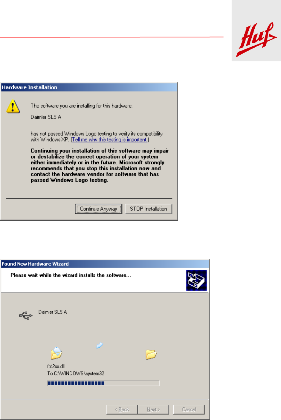
When the following dialog appears, click on: Continue Anyway
Fig.5: Installation warning
Wait for the files to be installed.
Fig. 6: Installation screen

Huf Tools
Automation · Prüftechnik · Formenbau · Kunststofftechnik · RFID Systeme · Lasertechnik
2015-12-07 User Manual LF-SPG V1.0 Page 9 of 18
After completion click on: Finish
Fig. 7: Completing the installation
Installation is complete now.
Huf Tools
Automation · Prüftechnik · Formenbau · Kunststofftechnik · RFID Systeme · Lasertechnik
2015-12-07 User Manual LF-SPG V1.0 Page 10 of 18
3.3.2. Installing the USB driver on Windows 7
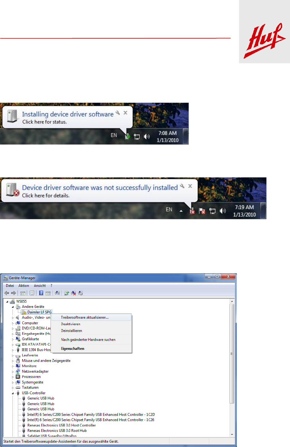
After connecting the LF-SPG to the computer for the first time it will be recognized automatically by Windows.
A message is shown on the screen, that the driver will be installed.
Fig. 8: Windows install message
After a short time an error message appears, indicating the driver was not installed.
Fig.9: Error Message
The driver has to be installed manually. Please open the device Manager. The device Manager is a
component of the operating system. To obtain more information about the device manager, please refer to the
Help of the operating system. Now there is displayed the unknown device with a Daimler LF SPG description.
Right click on the device and choose Update Driver Software.
Fig. 10: Device Manager

Huf Tools
Automation · Prüftechnik · Formenbau · Kunststofftechnik · RFID Systeme · Lasertechnik
2015-12-07 User Manual LF-SPG V1.0 Page 11 of 18
In the next dialog click on: Browse my computer for driver software.
Fig.11: Selection of automatic or manual installation
The driver files are in the USB Treiber folder on the CD ROM. Choose the folder and press Next.
Huf Tools
Automation · Prüftechnik · Formenbau · Kunststofftechnik · RFID Systeme · Lasertechnik
2015-12-07 User Manual LF-SPG V1.0 Page 12 of 18
Fig.12: Search for the driver
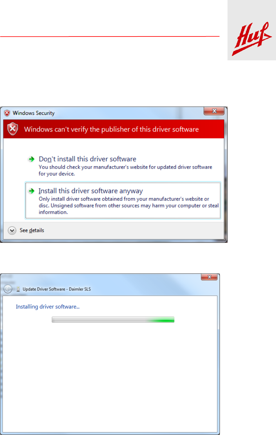
When the following dialog appears, click on: Install this driver software anyway.
Fig.13: Installation warning
Wait for the files to be installed.
Fig. 14: Installation screen
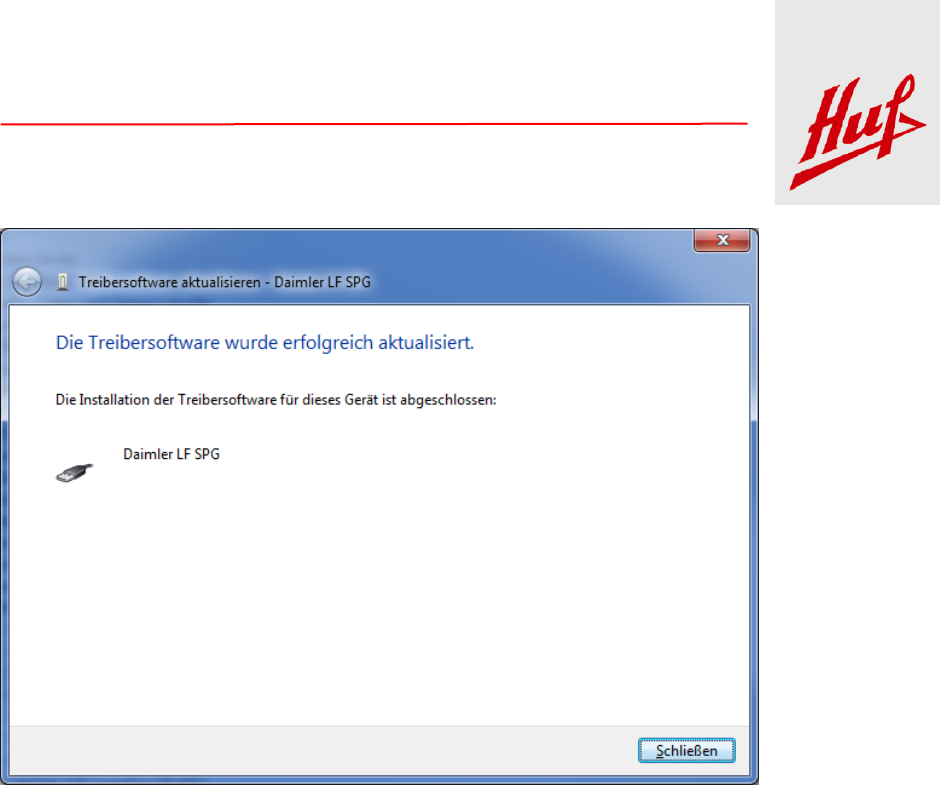
After completion click on: Close
Huf Tools
Automation · Prüftechnik · Formenbau · Kunststofftechnik · RFID Systeme · Lasertechnik
2015-12-07 User Manual LF-SPG V1.0 Page 13 of 18
Fig. 15: Completing the installation
Now installation is complete.

Huf Tools
Automation · Prüftechnik · Formenbau · Kunststofftechnik · RFID Systeme · Lasertechnik
2015-12-07 User Manual LF-SPG V1.0 Page 14 of 18
3.4. Installation of SPG.DLL
The SPG.DLL represents the software interface between an application program and the SPG. You must be
present on the target system, so that Daimler can access applications on their functions. The path where the
SPG.DLL must reside is different for 32-bit and 64-bit operating system versions.
3.4.1. 32bit operating system
When using the 32-bit DLL which SPG.DLL must be copied into the Windows System32 subdirectory.
3.4.2. 64bit operating system
The 32-bit DLL must be copied to the Windows subdirectory SysWOW64.
The 64-bit DLL must be copied into the Windows System32 subdirectory.

Huf Tools
Automation · Prüftechnik · Formenbau · Kunststofftechnik · RFID Systeme · Lasertechnik
2015-12-07 User Manual LF-SPG V1.0 Page 15 of 18
4. Status Indication by LED
Two status indicating LED’s are integrated in the LF-SPG. The upper LED indicates the status of the device
hardware, the second LED indicates the status of communication between the LF-SPG and car key.
Both LED’s can be illuminated in different colours and show the states described hereafter:
Description
Upper LED
Lower LED
SLS-Status
LF-SPG not working
off
off
LF-SPG in working condition
green
X
Firmware Download in progress
blue
off
Mercedes Car Key
Communication Status
Communication with the key
X
blue
Car key recognized
X
green
Error while communicating with car key
X
red
Table 1: LED’s color indication
Huf Tools
Automation · Prüftechnik · Formenbau · Kunststofftechnik · RFID Systeme · Lasertechnik
2015-12-07 User Manual LF-SPG V1.0 Page 16 of 18
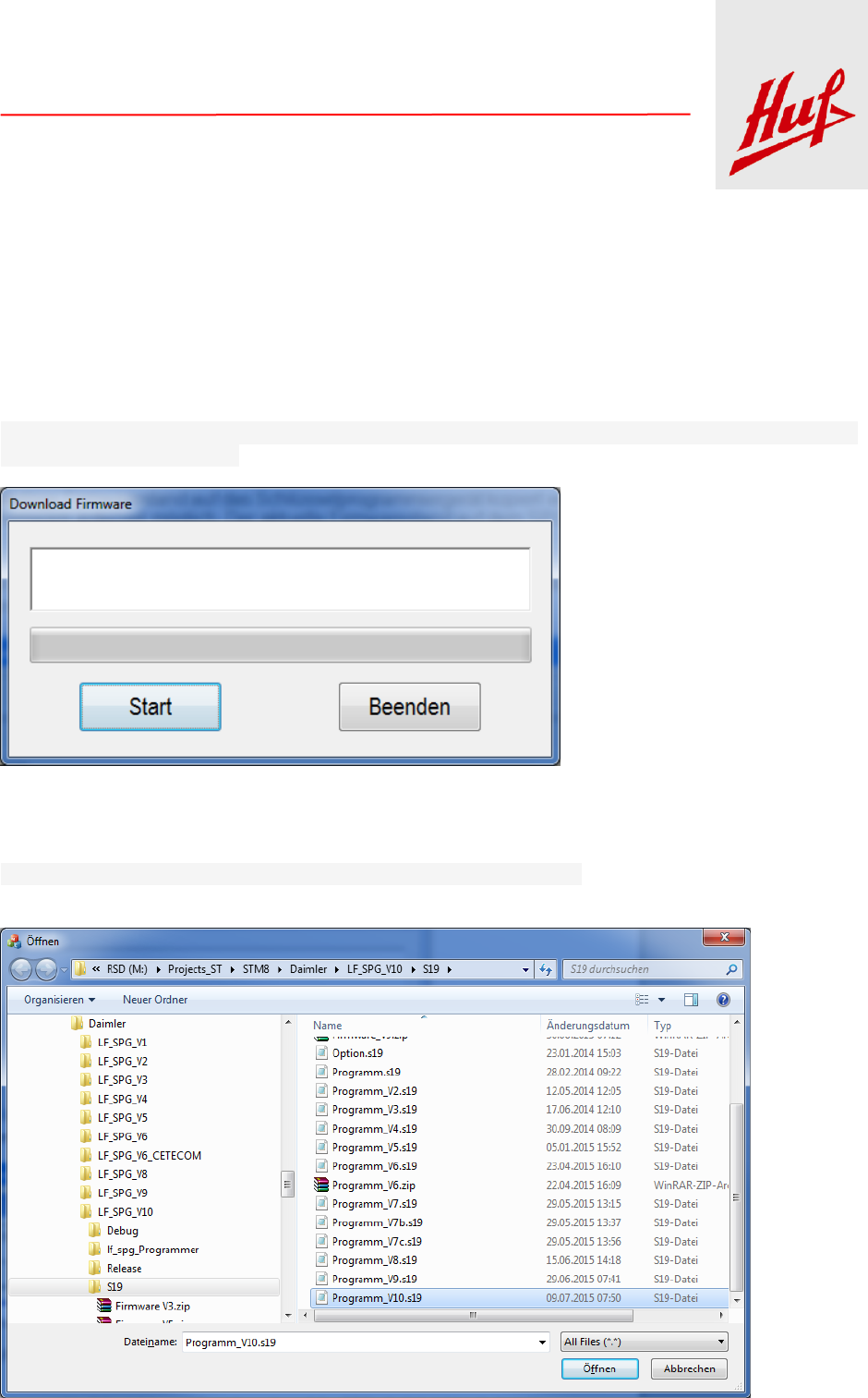
5. Flashing Firmware
To change the firmware of the device a separate Windows program (Flash Tool) is used. Before starting the
Flash Tool, any programs that access the key programmer, must be terminated.
Any firmware version can be copied to the key programmer, thus also downgrade the firmware is possible at
any time. The current firmware version on the SPG can not be saved.
To Flash the firmware, the Flash Tool needs to be launched. The execution location is irrelevant. No
additional files are required.
Fig. 16: User Interface of Flash Tool
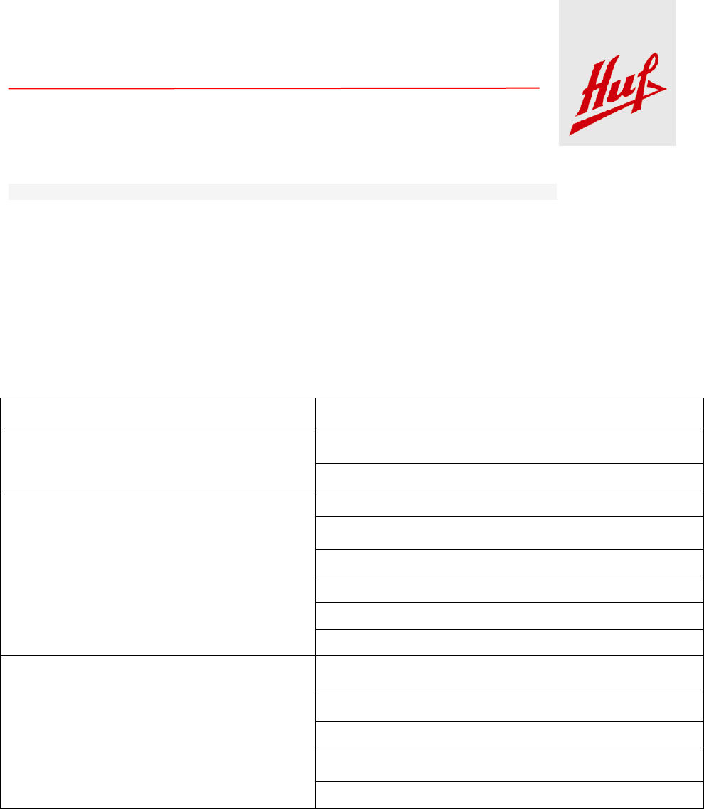
With "Start", a file dialog is opened, so you can select the firmware file to Flash into the LF-SPG. The Flash-
process is started by pressing the Open button.
The top LED of the SPS lights blue for the duration of the operation.
Fig. 17: File Dialog to choose the Firmware
Huf Tools
Automation · Prüftechnik · Formenbau · Kunststofftechnik · RFID Systeme · Lasertechnik
2015-12-07 User Manual LF-SPG V1.0 Page 17 of 18
The LF-SPG is restarted after successful Flash process and the new firmware is active.
After closing the program, the LF-SPG can be used again by another application program.
If the Flash process was not completed correctly or the LF-SPG is not working anymore, restart the Flash
process.
6. Error list
Possible errors are listed in the table below :
Description
Actions
Upper LED doesn’t light
SLS might be not correctly connected. Check the USB
connection and the Power supply connection
Hardware Error, return the device
No connection to the LF-SPG
Download interrupted. Start Download again
LF-SPG might be not correctly connected. Check the USB
connection and if your PC is working
Driver not installed, please install the driver
Application not installed, please install the application
Check power supply, properly connected?
Hardware Error, please return the device
Communication with the car key not successful
IR connection disturbed, insert key all the way into the
receptacle
IR connection disturbed, Key defect? Please try another
car key.
LF connection disturbed, please hang up key again
LF connection disturbed, defect key? Please try a different
key.
Hardware Error, please return the device
Table 2: Error list

Huf Tools
Automation · Prüftechnik · Formenbau · Kunststofftechnik · RFID Systeme · Lasertechnik
2015-12-07 User Manual LF-SPG V1.0 Page 18 of 18
7. Declaration of Conformity
Fig. 18: Declaration of Conformity

Huf Tools
Automation · Prüftechnik · Formenbau · Kunststofftechnik · RFID Systeme · Lasertechnik
2015-12-14 regulatory notices for Canada in French Page 1 of 1
Le modèle d'homologation au Canada pour notre modelé
LFSPG125218
Le présent appareil est conforme aux CNR d'Industrie Canada applicables aux appareils
radio
exempts de licence. L'exploitation est autorisée aux deux conditions suivantes:
(1) l'appareil ne doit pas produire de brouillage, et
(2) l'appareil doit accepter tout brouillage radioélectrique subi, même si le brouillage
est susceptible d'en compromettre le fonctionnement.
IC ID: 4008A-LFSPG125218
Avec plaisir,
Daniel Klenner
Huf Tools GmbH Velbert (Reg. Nr. IC: 4008A)
Güterstr. 17 42551 Velbert Allemagne
Tel.: +49 2051 2767-773: Fax:+49 2051 2767-1773
Daniel.Klenner@huf-tools.de: