Humatics P440-A Ultra Wideband (UWB) radio transceiver User Manual
TDC Acquisition Holdings Inc. Ultra Wideband (UWB) radio transceiver
UserManual.wiki
>
Humatics
>
P440 A User Manual
User Manual
Navigation menu
Upload a User Manual
Namespaces
Wiki Guide
HTML
PDF
Info
Views
User Manual
Discussion / Help
Navigation
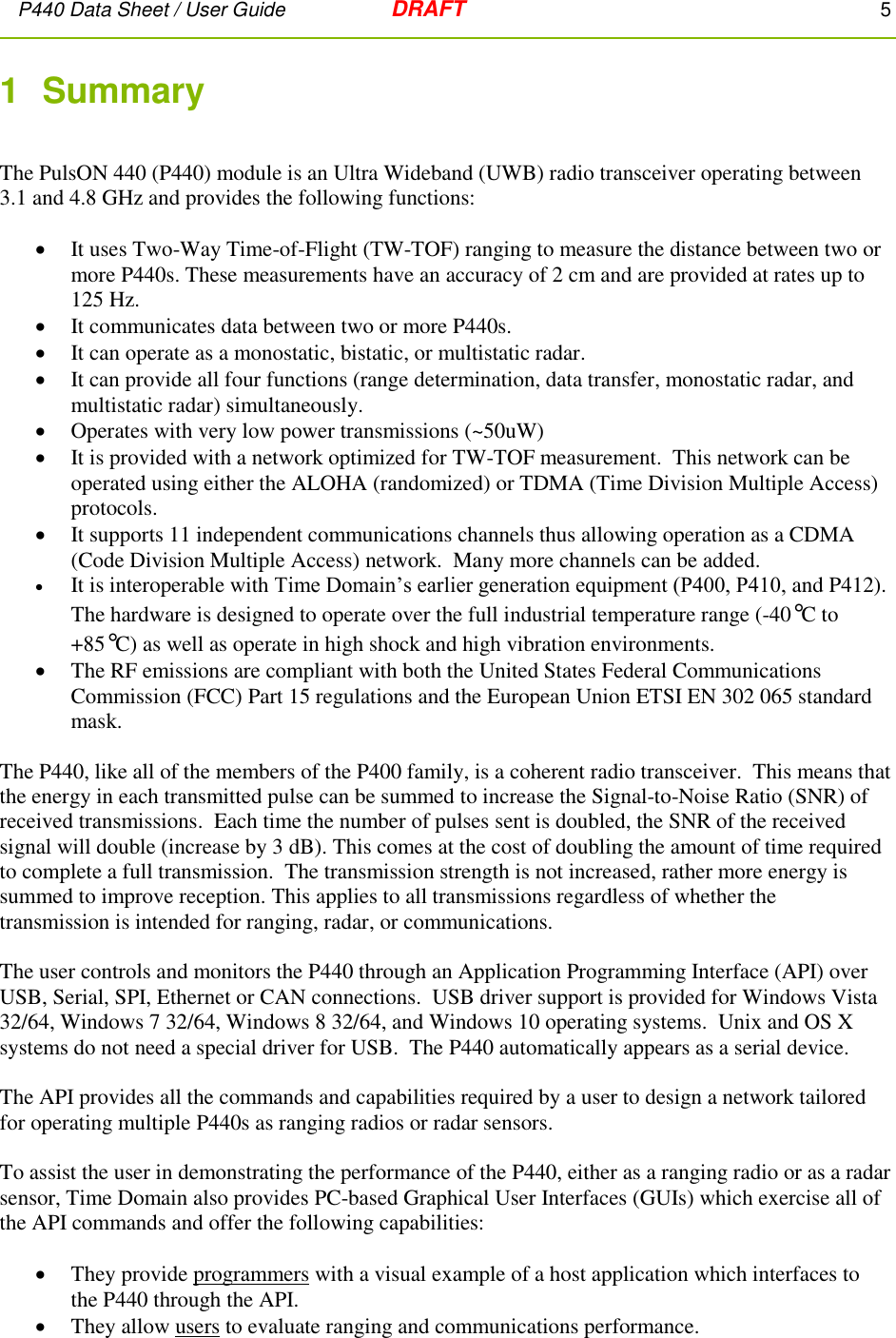
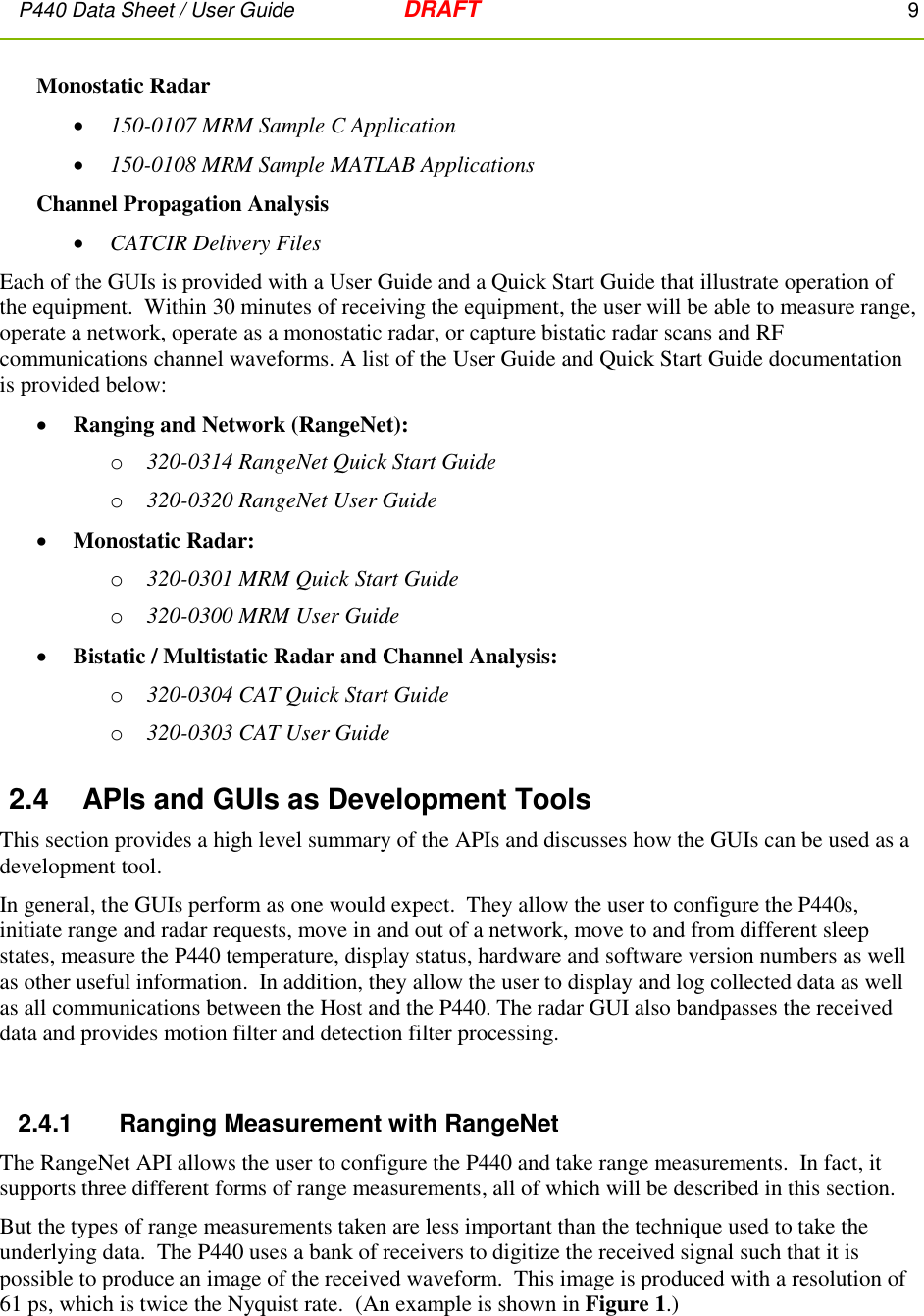
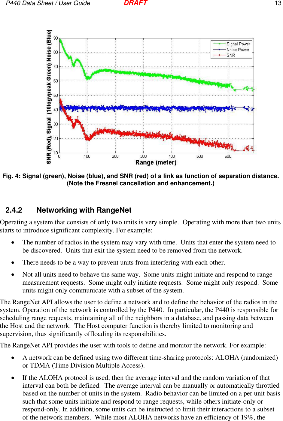
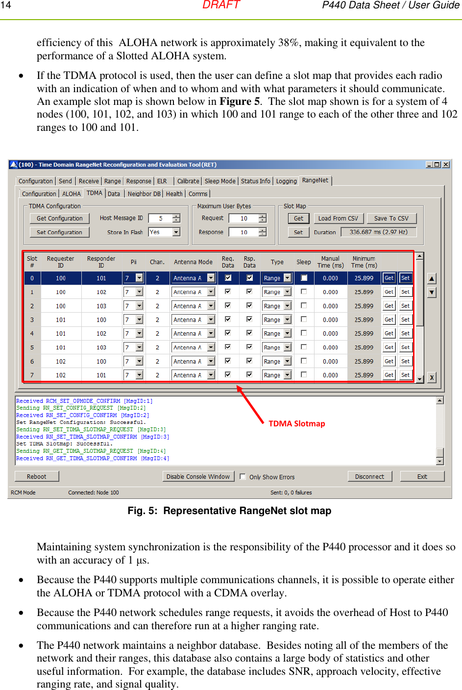
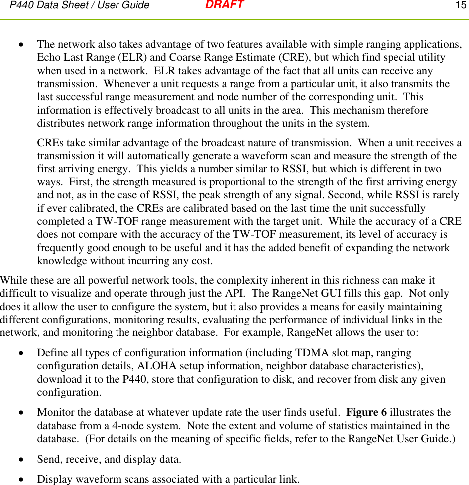
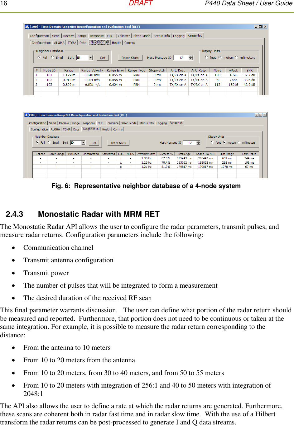
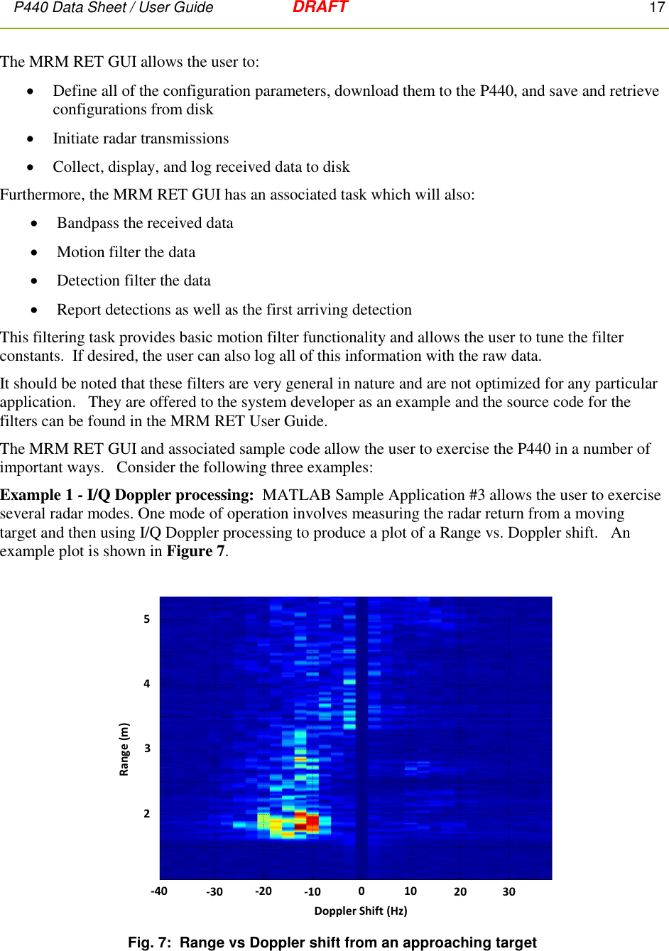
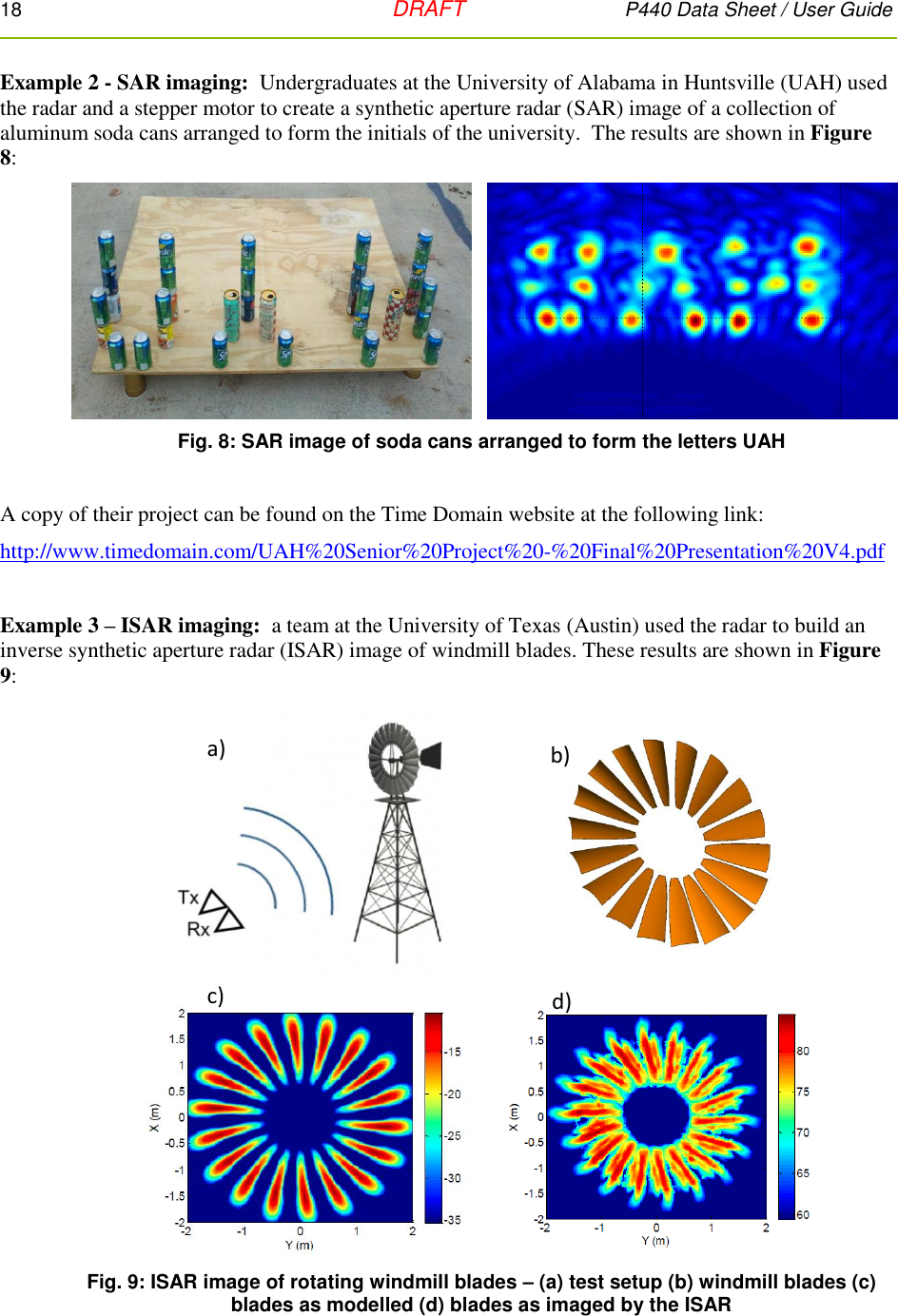
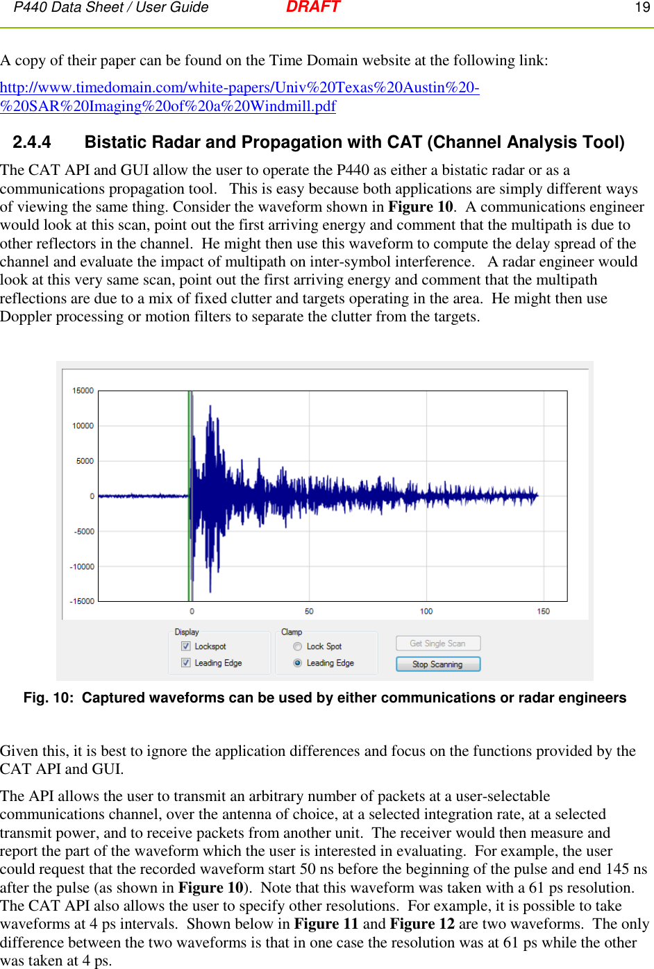
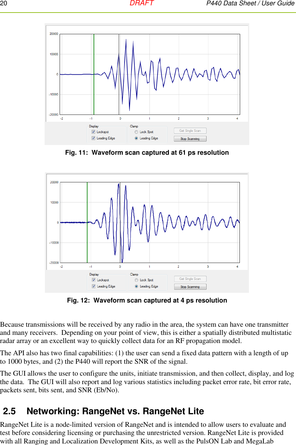
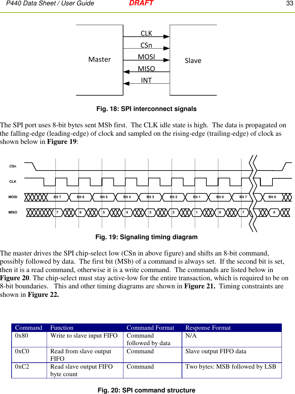
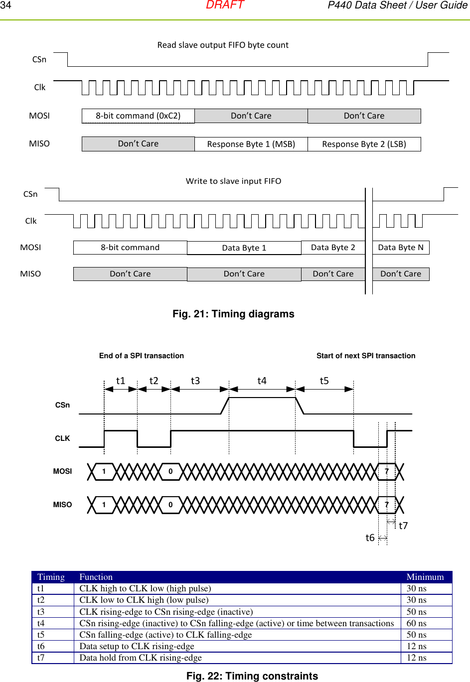
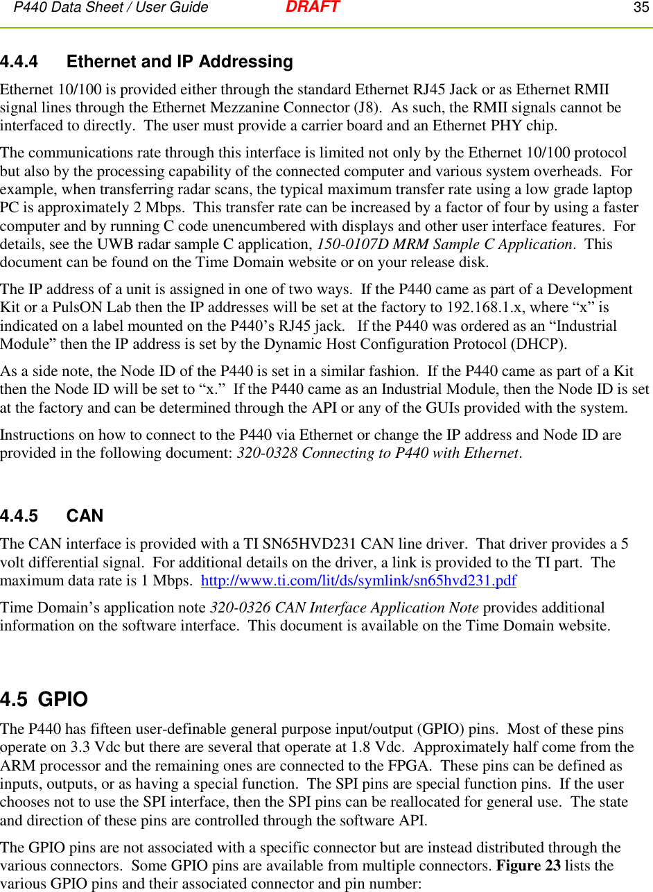
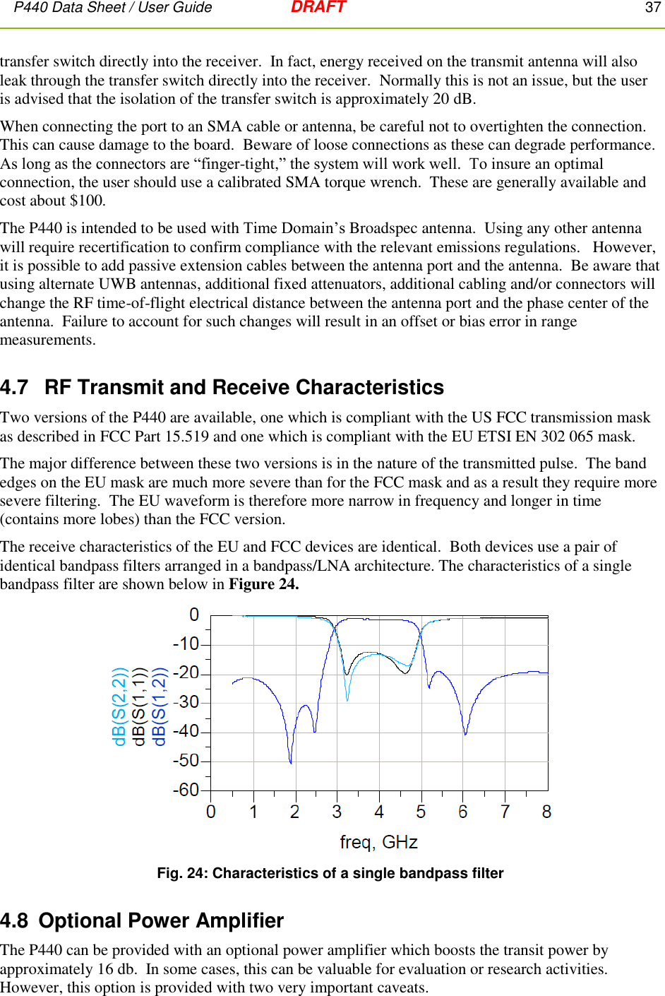
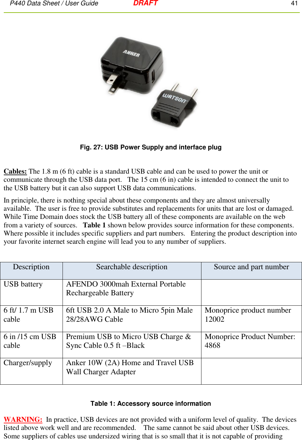
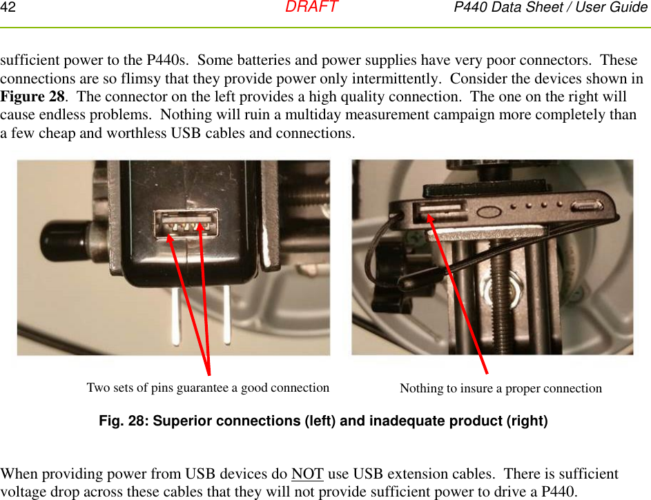
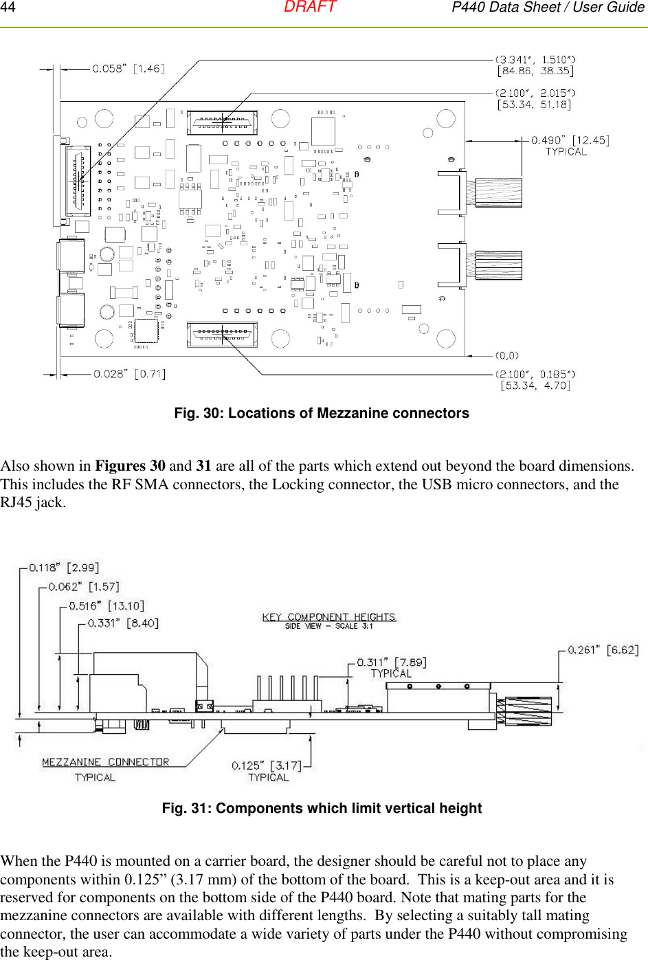
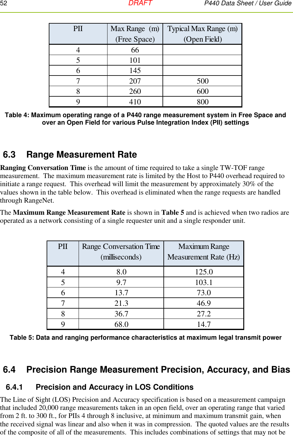
![P440 Data Sheet / User Guide DRAFT 43 5 Mechanical Interface Figures 29, 30, 31, 32, and 33 provide the information which defines the board size, the height of key components, as well as the location and dimensions of all connectors. Dimensions are shown in British Imperial units (inches). Dimensions shown in [brackets] are in metric (millimeters). Table 2 lists the part numbers of all connectors and their respective mating pair. Fig. 29: P440 board dimensions The six mounting holes have an inside diameter of 0.125 inches (3.175 mm) and are sized for a #4 screw. The pads have an outside diameter of 0.250 inches (6.35 mm). The minimum distance between the center of the hole and the closest component or circuit trace is 0.140” (3.556 mm). It is anticipated that the number of mounting holes, size of the holes and placement separations are sufficient to satisfy most vibration requirements. Several customers have already satisfactorily tested the vibration performance of the P440 in extremely challenging end applications. The P440 board is built to IPC Class 2 standards. The tolerances associated with hole size and centering are consistent with this standard.](https://usermanual.wiki/Humatics/P440-A/User-Guide-2878444-Page-43.png)