Humatics P440-A Ultra Wideband (UWB) radio transceiver User Manual
TDC Acquisition Holdings Inc. Ultra Wideband (UWB) radio transceiver
Humatics >
User Manual


2 DRAFT P440 Data Sheet / User Guide
Copyright
All rights reserved. Time Domain® 2001-2015. All rights reserved.
Trademarks
Time Domain®, PulsON®, and “PulsON Triangle” logo are registered trademarks of Time Domain. Microsoft® and
Windows Vista®, Windows 7®, Windows 8®, and Windows 10® are registered trademarks of Microsoft Corporation.
MATLAB® is a registered trademark of MathWorks, Inc. Any trademarks, trade names, service marks or service names
owned or registered by any other company and used in this manual are the property of its respective company.
Rights
Rights to use this documentation are set forth in the PulsON Products Terms and Conditions of Sale.
Document Information
Time Domain reserves the right to change product specifications without notice. Any changes to the functionality or
specifications will be issued as specific errata sheets or will be incorporated in new versions of this document. The latest
version of this document and future documents can be found on the Time Domain website. The name/number and date of
this document can be found on the left side of the cover page.
Regulatory Approvals
The P440, as supplied by Time Domain, has not yet been certified for use in any particular geographic region by the
appropriate regulatory body governing radio emissions in that region. However, other members of the P400 series of
devices have received such certification for use in the United States and the P440 is currently in the process of being tested
for certification in the US. This certification is expected to be received later in 2015. This will be followed by a similar
effort in Europe in 2016.
All final products developed by the user which incorporate the P440 must be approved by the relevant authority governing
radio emissions for the target market country(s). The User bears all responsibility for obtaining such approval(s).

P440 Data Sheet / User Guide DRAFT 3
Table of Contents
1 SUMMARY ................................................................................................................... 5
2 P440 SOFTWARE ....................................................................................................... 7
2.1 P440 Embedded Software ....................................................................................................... 7
2.2 Application Programming Interfaces (APIs) ......................................................................... 7
2.3 Graphical User Interfaces (GUIs) and Sample Code ............................................................ 8
2.4 APIs and GUIs as Development Tools .................................................................................. 9
2.4.1 Ranging Measurement with RangeNet ................................................................................................ 9
2.4.2 Networking with RangeNet ................................................................................................................ 13
2.4.3 Monostatic Radar with MRM RET ...................................................................................................... 16
2.4.4 Bistatic Radar and Propagation with CAT (Channel Analysis Tool) ................................................... 19
2.5 Networking: RangeNet vs. RangeNet Lite ........................................................................... 20
2.6 Software Support ................................................................................................................... 21
3 HARDWARE BLOCK DIAGRAM ................................................................................22
4 ELECTRICAL INTERFACES ......................................................................................24
4.1 Connecting to the P440 ......................................................................................................... 25
4.2 Connector Pinouts ................................................................................................................ 25
4.3 Powering and Grounding the Unit ....................................................................................... 29
4.3.1 Powering the P440 through the USB Power jack vs Locking & Mezzanine connectors ..................... 29
4.3.2 Reverse polarity protection ................................................................................................................ 29
4.3.3 Two means of powering the P440 ...................................................................................................... 29
4.3.4 Chassis Ground ................................................................................................................................. 30
4.3.5 Fused_Ground and Digital_Ground ................................................................................................... 30
4.3.6 P440 Power requirements ................................................................................................................. 30
4.4 Host to P440 Interface Options ............................................................................................ 31
4.4.1 USB 2.0 High Speed Device .............................................................................................................. 32
4.4.2 User Serial ......................................................................................................................................... 32
4.4.3 SPI ..................................................................................................................................................... 32
4.4.4 Ethernet and IP Addressing ............................................................................................................... 35
4.4.5 CAN ................................................................................................................................................... 35
4.5 GPIO ........................................................................................................................................ 35
4.6 Antenna Ports ........................................................................................................................ 36
4.7 RF Transmit and Receive Characteristics .......................................................................... 37

4 DRAFT P440 Data Sheet / User Guide
4.8 Optional Power Amplifier ..................................................................................................... 37
4.9 Indicator Lights ..................................................................................................................... 38
4.10 Heat Management ................................................................................................................. 39
4.11 Accessories ........................................................................................................................... 39
4.11.1 Enclosure ......................................................................................................................................40
4.11.2 Power Supply/Charger with Battery and cables. ...........................................................................40
5 MECHANICAL INTERFACE ....................................................................................... 43
6 TECHNICAL SPECIFICATIONS ................................................................................. 47
6.1 Summary of Key Performance Parameters. ....................................................................... 47
6.2 Maximum Operating Range of a P440 Radio ..................................................................... 50
6.3 Range Measurement Rate .................................................................................................... 52
6.4 Precision Range Measurement Precision, Accuracy, and Bias ....................................... 52
6.4.1 Precision and Accuracy in LOS conditions. ........................................................................................52
6.4.2 Precision and Accuracy in NLOS conditions ......................................................................................53
6.4.3 Bias and Calibration ...........................................................................................................................53
6.5 CRE Range Measurement Precision and Accuracy .......................................................... 54
6.6 Data Communications Rate and Throughput .................................................................... 54
6.7 Operating Range of P440 Radar .......................................................................................... 55
6.8 P440 Version Differences ..................................................................................................... 55
7 BROADSPEC ANTENNA ........................................................................................... 56
8 REGULATORY COMPLIANCE .................................................................................. 57
8.1 Compliance with the U.S. FCC regulations ........................................................................ 57
8.2 Compliance with the EU ETSI standards ............................................................................ 59
9 IMPORT/EXPORT CONSIDERATIONS ..................................................................... 60
10 CONFIGURATION AND ORDERING INFORMATION ............................................... 61

P440 Data Sheet / User Guide DRAFT 5
1 Summary
The PulsON 440 (P440) module is an Ultra Wideband (UWB) radio transceiver operating between
3.1 and 4.8 GHz and provides the following functions:
It uses Two-Way Time-of-Flight (TW-TOF) ranging to measure the distance between two or
more P440s. These measurements have an accuracy of 2 cm and are provided at rates up to
125 Hz.
It communicates data between two or more P440s.
It can operate as a monostatic, bistatic, or multistatic radar.
It can provide all four functions (range determination, data transfer, monostatic radar, and
multistatic radar) simultaneously.
Operates with very low power transmissions (~50uW)
It is provided with a network optimized for TW-TOF measurement. This network can be
operated using either the ALOHA (randomized) or TDMA (Time Division Multiple Access)
protocols.
It supports 11 independent communications channels thus allowing operation as a CDMA
(Code Division Multiple Access) network. Many more channels can be added.
It is interoperable with Time Domain’s earlier generation equipment (P400, P410, and P412).
The hardware is designed to operate over the full industrial temperature range (-40°C to
+85°C) as well as operate in high shock and high vibration environments.
The RF emissions are compliant with both the United States Federal Communications
Commission (FCC) Part 15 regulations and the European Union ETSI EN 302 065 standard
mask.
The P440, like all of the members of the P400 family, is a coherent radio transceiver. This means that
the energy in each transmitted pulse can be summed to increase the Signal-to-Noise Ratio (SNR) of
received transmissions. Each time the number of pulses sent is doubled, the SNR of the received
signal will double (increase by 3 dB). This comes at the cost of doubling the amount of time required
to complete a full transmission. The transmission strength is not increased, rather more energy is
summed to improve reception. This applies to all transmissions regardless of whether the
transmission is intended for ranging, radar, or communications.
The user controls and monitors the P440 through an Application Programming Interface (API) over
USB, Serial, SPI, Ethernet or CAN connections. USB driver support is provided for Windows Vista
32/64, Windows 7 32/64, Windows 8 32/64, and Windows 10 operating systems. Unix and OS X
systems do not need a special driver for USB. The P440 automatically appears as a serial device.
The API provides all the commands and capabilities required by a user to design a network tailored
for operating multiple P440s as ranging radios or radar sensors.
To assist the user in demonstrating the performance of the P440, either as a ranging radio or as a radar
sensor, Time Domain also provides PC-based Graphical User Interfaces (GUIs) which exercise all of
the API commands and offer the following capabilities:
They provide programmers with a visual example of a host application which interfaces to
the P440 through the API.
They allow users to evaluate ranging and communications performance.

6 DRAFT P440 Data Sheet / User Guide
They allow users to evaluate the radar performance through use of a sample Motion Filter,
sample Detection Processor, and a graphical display of raw and processed radar scans.
They allow system analysts to visualize, collect, and log raw ranging and radar data such that
it is possible to develop algorithms/strategies optimized for the chosen product application.
They allow users to operate multiple P440s to form a network of ranging radios.
Time Domain also provides sample C and MATLAB code for demonstrating the interface and
performance of the hardware.
The objective of providing the GUIs, sample C and sample MATLAB code is to supply programmers
with several example interfaces and implementations which the user may then replace or tailor with
custom code optimized for their particular needs and applications.
This technology has been used in a wide variety of applications. For example, it has been used:
To report safe distances between rail vehicles
To allow robots to follow leaders at a safe distance
To provide robots with location knowledge
To guide drones as they fly
To precisely locate vehicles in tunnels and mines
To maintain safe distances between construction vehicles
To measure the respiration rate of patients
To locate and track people as they move through an area
To precisely measure the length of long structures
To precisely measure the location of specific features in buildings
To track forklifts as they move through an area
For various doctoral and post-doctoral research projects
To teach university undergraduates about RF, radar, and signal processing
This document describes the P440 hardware and software. This discussion is subdivided into the
following subsections.
Section 2 P440 Software
Section 3 Hardware Block Diagram
Section 4 Electrical Interfaces
Section 5 Mechanical Interface
Section 6 Technical Specifications
Section 7 Broadspec Antenna
Section 8 Regulatory Compliance
Section 9 Import/Export Considerations
Section 10 Configuration and Ordering Information
Additional information including all of the documents referenced in this section can be found on the
web at www.timedomain.com. This includes: the API, software manuals, application notes, white
papers, examples, published papers, sample C code, sample MATLAB code, and more.

P440 Data Sheet / User Guide DRAFT 7
2 P440 Software
The P440 software consists of five elements:
Embedded software operating on the P440 module
The Application Programming Interface (API) which defines the interface between the P440
and a Host processor
GUIs provided to (1) illustrate operation of the P440 and (2) provide an analytical tool for
characterizing performance
Sample C and MATLAB code to assist the user in developing custom applications
Network support to enable systems of P440s to range and communicate efficiently
In addition, Time Domain is committed to periodically adding new features and capabilities through
software upgrades.
2.1 P440 Embedded Software
The P440 is a microprocessor-based UWB platform. The onboard processor has three principal
functions:
It is responsible for transmitting and receiving UWB pulses.
It handles all communications with the user’s Host processor (typically a PC or single-board
computer). The format of these communications is defined by a set of three APIs, each
tailored to a specific application. The user has a choice of communicating with the P440 over
5 different physical interfaces: Ethernet, USB, SPI, Serial, and CAN.
When instructed to act as a network, the onboard processor:
o Assumes all responsibilities for scheduling communications and range requests
o Provides the Host with status update information
o Handles supervisory commands sent by the Host
This increases the ranging update rate and significantly offloads the Host processor.
For details on interfaces, refer to:
320-087 Using the USB and Serial Interfaces
2.2 Application Programming Interfaces (APIs)
There are three different APIs:
Range measurement and network commands are defined in the document
320-0313 RangeNet API Specification

8 DRAFT P440 Data Sheet / User Guide
Monostatic Radar commands are defined in the document
320-0298 Monostatic Radar API Specification
Bistatic radar and communications channel modeling commands are defined in the document
330-0305 Channel Analysis Tool API Specification
While useful, this separation is artificial in that the embedded software in the P440 can handle all
three APIs. If the embedded code in the P440 is updated, then all three APIs will be updated as well.
Furthermore, the user is free to develop applications that incorporate commands from any or all of
these APIs. For example, this ability allows the user to create ranging measurement networks that
incorporate bistatic and multistatic radar and also communicate data.
The high-level features of the APIs are discussed in Section 2.4 – APIs and GUIs as Development
Tools.
2.3 Graphical User Interfaces (GUIs) and Sample Code
Mastering all of the commands in an API (or in this case, a set of three APIs) can be a time-
consuming task, especially when the APIs have a rich command set. To accelerate this learning
process, Time Domain provides three example Graphical User Interfaces (GUIs). These GUIs
operate on a PC and exercise all of the API commands. They also display received data and allow the
user to log all received data or API messages sent or received by the Host. Each GUI focuses on one
particular API:
RangeNet RET is used to demonstrate simple point-to-point ranging and communications
under the control of a host processor as well as operation as a full ranging network under
control of the P440.
MRM RET is used to demonstrate monostatic radar.
Channel Analysis Tool (CAT) is used to demonstrate either (a) bistatic and multistatic radar
or (b) communications channel propagation analysis.
In addition, Time Domain also provides sample C and sample MATLAB code for each application
area. The sample C code enables embedded programmers to quickly interface to the P440. The
sample MATLAB code enables system analysts to quickly construct experiments to investigate and
evaluate performance. The sample code also includes parsers for extracting information from the
logfiles.
The sample code includes the following:
Ranging and Network (RangeNet)
150-0117 – RangeNet Sample C Applications
150-0123 – RangeNet Localization Demo (MATLAB-based executable)
150-0124 – Localization Demo (command line based executable)
150-0118 – RangeNet Sample MATLAB Applications
150-0103 – Ranging Sample C Applications
150-0104 – Ranging Sample MATLAB Applications

P440 Data Sheet / User Guide DRAFT 9
Monostatic Radar
150-0107 MRM Sample C Application
150-0108 MRM Sample MATLAB Applications
Channel Propagation Analysis
CATCIR Delivery Files
Each of the GUIs is provided with a User Guide and a Quick Start Guide that illustrate operation of
the equipment. Within 30 minutes of receiving the equipment, the user will be able to measure range,
operate a network, operate as a monostatic radar, or capture bistatic radar scans and RF
communications channel waveforms. A list of the User Guide and Quick Start Guide documentation
is provided below:
Ranging and Network (RangeNet):
o 320-0314 RangeNet Quick Start Guide
o 320-0320 RangeNet User Guide
Monostatic Radar:
o 320-0301 MRM Quick Start Guide
o 320-0300 MRM User Guide
Bistatic / Multistatic Radar and Channel Analysis:
o 320-0304 CAT Quick Start Guide
o 320-0303 CAT User Guide
2.4 APIs and GUIs as Development Tools
This section provides a high level summary of the APIs and discusses how the GUIs can be used as a
development tool.
In general, the GUIs perform as one would expect. They allow the user to configure the P440s,
initiate range and radar requests, move in and out of a network, move to and from different sleep
states, measure the P440 temperature, display status, hardware and software version numbers as well
as other useful information. In addition, they allow the user to display and log collected data as well
as all communications between the Host and the P440. The radar GUI also bandpasses the received
data and provides motion filter and detection filter processing.
2.4.1 Ranging Measurement with RangeNet
The RangeNet API allows the user to configure the P440 and take range measurements. In fact, it
supports three different forms of range measurements, all of which will be described in this section.
But the types of range measurements taken are less important than the technique used to take the
underlying data. The P440 uses a bank of receivers to digitize the received signal such that it is
possible to produce an image of the received waveform. This image is produced with a resolution of
61 ps, which is twice the Nyquist rate. (An example is shown in Figure 1.)
10 DRAFT P440 Data Sheet / User Guide
Fig.1: A typical received waveform: signal magnitude (relative strength) vs time (increments of
61ps)
This is a powerful capability for several reasons:
Oversampling enables correlation processing, thereby producing reliable sub-centimeter
range estimates.
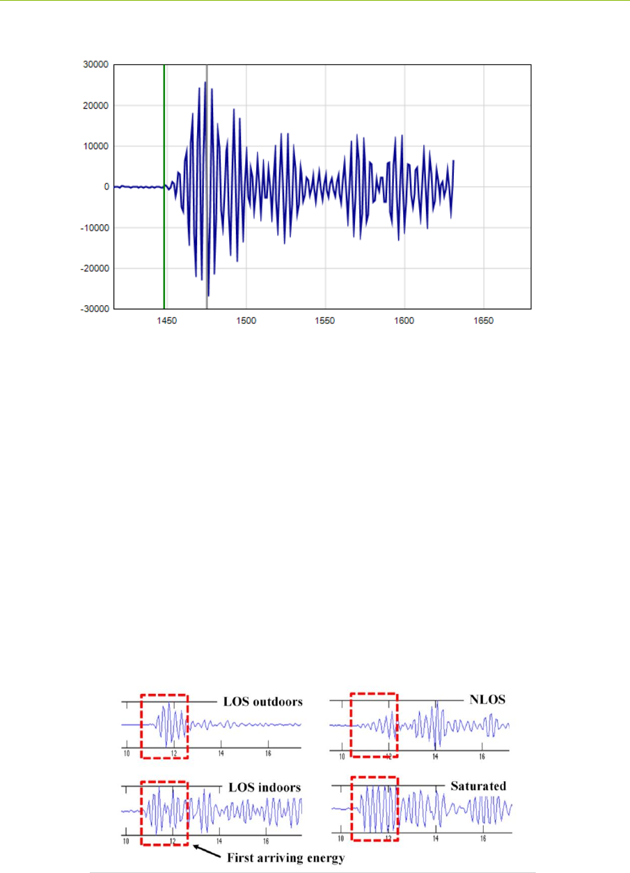
By analyzing the shape of the received waveform it is possible to determine importation
characteristics of the channel such as (a) whether or not the signal is clear or non-line-of -
sight (NLOS), (b) determine if the signal is in compression, and (c) whether or not the signal
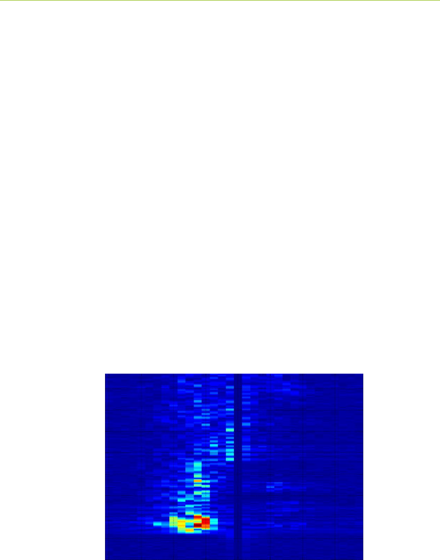
is corrupted by multipath or Fresnel effects. This is illustrated in Figure 2.
It is possible to measure the signal strength of the first arriving pulse as opposed to the
strength of the largest multipath signal.
It is possible to measure the background noise level. That, in conjunction with the signal
strength measurement, allows the measurement of the received SNR.
It is possible to characterize the received waveform and produce an error estimate of the
range measurement estimate.
Fig.2: Received waveforms captured at 61ps intervals (2x Nyquist) in a variety of
environments

P440 Data Sheet / User Guide DRAFT 11
This underlying capability allows the generation of the following three different types of range
measurements:
Precision Range Measurements (PRM) are taken using the TW-TOF ranging technique. These
readings typically have high accuracy and are provided with estimates of range error as well as flags
that warn of possible errors. The user can use these range error estimates to drive a Kalman Filter.
The flags can be used to disregard inaccurate readings.
Coarse Range Estimates (CRE) are analogous to RSSI (received signal strength indication) range
estimates produced by continuous wave RF ranging systems in that they relate the strength of the
received signal to range. They are different in two important ways. First, the signal strength reported
is based on the strength of the first arriving energy and not on the strongest overall energy. This
ensures that large signals produced by constructive multipath do not introduce false readings.
Second, the signal strength reported is automatically calibrated based on the last successful Precision
Range Measurement.
Echo Last Range (ELR) measurements are Precision Range Measurements which have been taken
between two other radios in the system. In other words, any time a unit takes a PRM it will broadcast
the last range measurement to any other radios in the area. For example, if Unit A measures the
distance between Unit A and Unit B, it will broadcast this range measurement to Units C, D, E, etc.,
whenever it next initiates a range measurement. This is an alternate way of automatically distributing
range information through a system.
Finally, the P440 uses the API to make the range measurements, error flags, range error estimates,
signal strength measurements, measurements of background noise, and waveform measurements
available to the Host processor.
The RangeNet GUI exercises each of the API commands, thereby allowing the user to configure the
unit and take range measurements. But the GUI adds an extra level of system software in that it will
allow the user to:
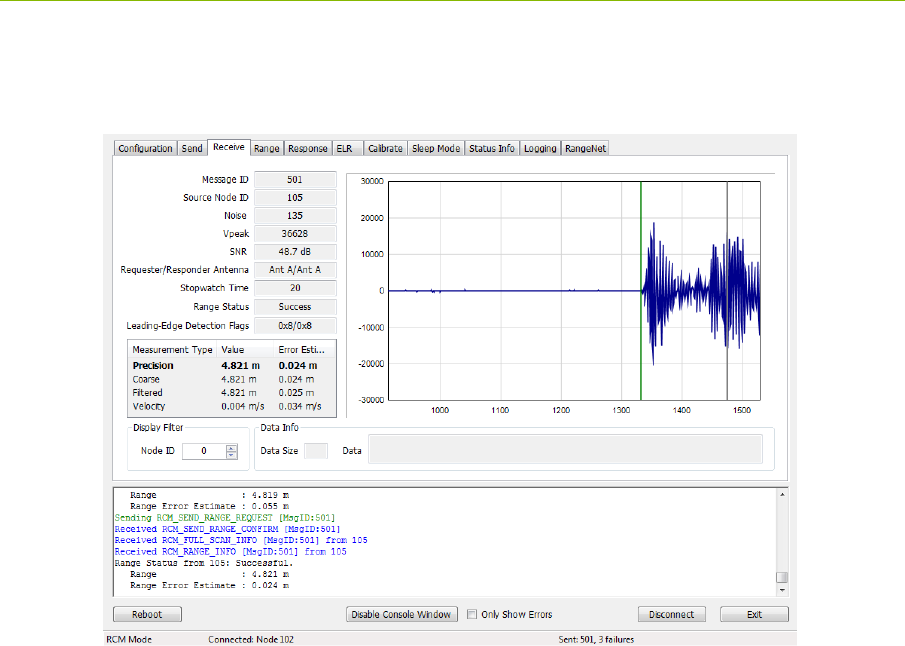
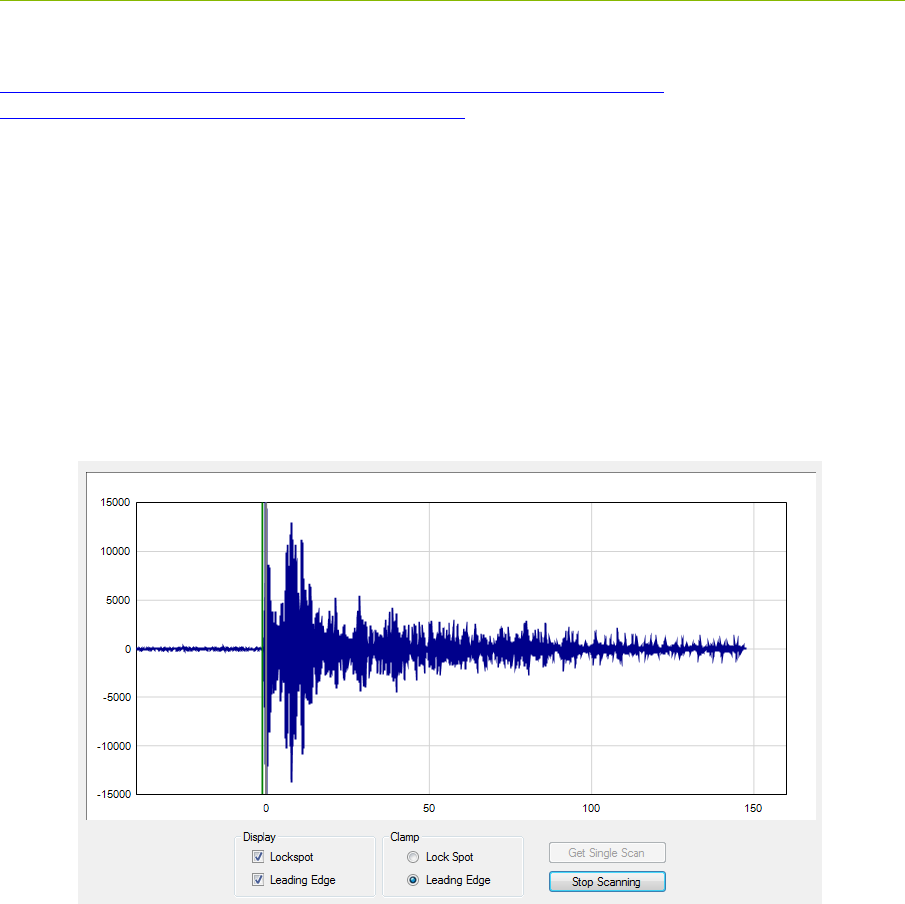
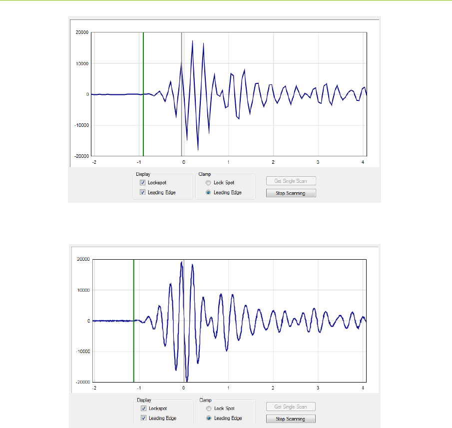
Capture, display to the screen, and log waveforms to disk. Figure 3 illustrates a
representative waveform as displayed by the GUI.
Request a single range measurement, a fixed number of measurements, or a continuous series
of range measurements.
Display the signal strength, noise, and SNR of the received signal.
Display quality metrics that provide a warning if the reading is suspect.
Calculate performance statistics. For example, if the user requests a finite number of ranges,
the GUI will compute the range success rate, the average range, the standard deviation of the
range measurements, the average SNR of the readings, and the standard deviation of the
SNR. These statistics are valuable for determining the quality of service the user can expect.
The system will also filter the received readings using the quality metrics and provide the
same statistics.
Determine if there are interference sources in the area.
Recalibrate a given link such that the bias or offset inherent in a range measurement can be
compensated.
Allow the user to easily enter and transmit data.
Allow the user to receive and display data.
Log all messages exchanged between the host and connected P440.
12 DRAFT P440 Data Sheet / User Guide
Display range measurements taken between other units in the area for which the connected
P440 is not a direct participant.
Fig. 3: Typical waveform as displayed by the GUI
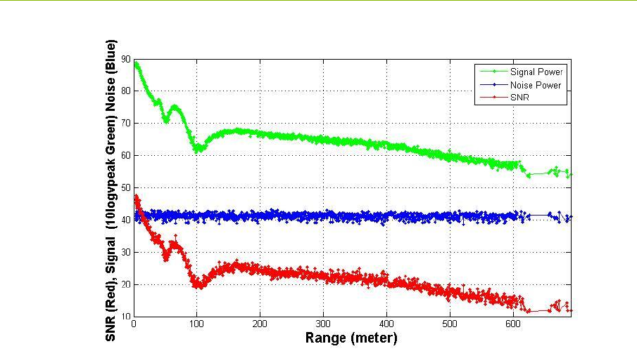
The ability to log data also allows the user to plot performance as a function of range. This is an
excellent tool for evaluating signal propagation in a given area. For example, the information shown
in Figure 4 was collected as the distance between two units was increased. Basically, one unit was
stationary while the second unit was slowly driven away. Figure 4 shows a plot of the Signal, Noise,
and SNR as a function of separation distance. In this figure one can observe several items of note:
There is a Fresnel cancellation at 40, 60, and 100 meters.
There is a Fresnel enhancement at ranges greater than 120 meters.
The noise floor is constant; therefore there are no significant interference sources in the
vicinity.
P440 Data Sheet / User Guide DRAFT 13
Fig. 4: Signal (green), Noise (blue), and SNR (red) of a link as function of separation distance.
(Note the Fresnel cancellation and enhancement.)
2.4.2 Networking with RangeNet
Operating a system that consists of only two units is very simple. Operating with more than two units
starts to introduce significant complexity. For example:
The number of radios in the system may vary with time. Units that enter the system need to
be discovered. Units that exit the system need to be removed from the network.
There needs to be a way to prevent units from interfering with each other.
Not all units need to behave the same way. Some units might initiate and respond to range
measurement requests. Some might only initiate requests. Some might only respond. Some
units might only communicate with a subset of the system.
The RangeNet API allows the user to define a network and to define the behavior of the radios in the
system. Operation of the network is controlled by the P440. In particular, the P440 is responsible for
scheduling range requests, maintaining all of the neighbors in a database, and passing data between
the Host and the network. The Host computer function is thereby limited to monitoring and
supervision, thus significantly offloading its responsibilities.
The RangeNet API provides the user with tools to define and monitor the network. For example:
A network can be defined using two different time-sharing protocols: ALOHA (randomized)
or TDMA (Time Division Multiple Access).
If the ALOHA protocol is used, then the average interval and the random variation of that
interval can both be defined. The average interval can be manually or automatically throttled
based on the number of units in the system. Radio behavior can be limited on a per unit basis
such that some units initiate and respond to range requests, while others initiate-only or
respond-only. In addition, some units can be instructed to limit their interactions to a subset
of the network members. While most ALOHA networks have an efficiency of 19%, the
14 DRAFT P440 Data Sheet / User Guide
efficiency of this ALOHA network is approximately 38%, making it equivalent to the
performance of a Slotted ALOHA system.
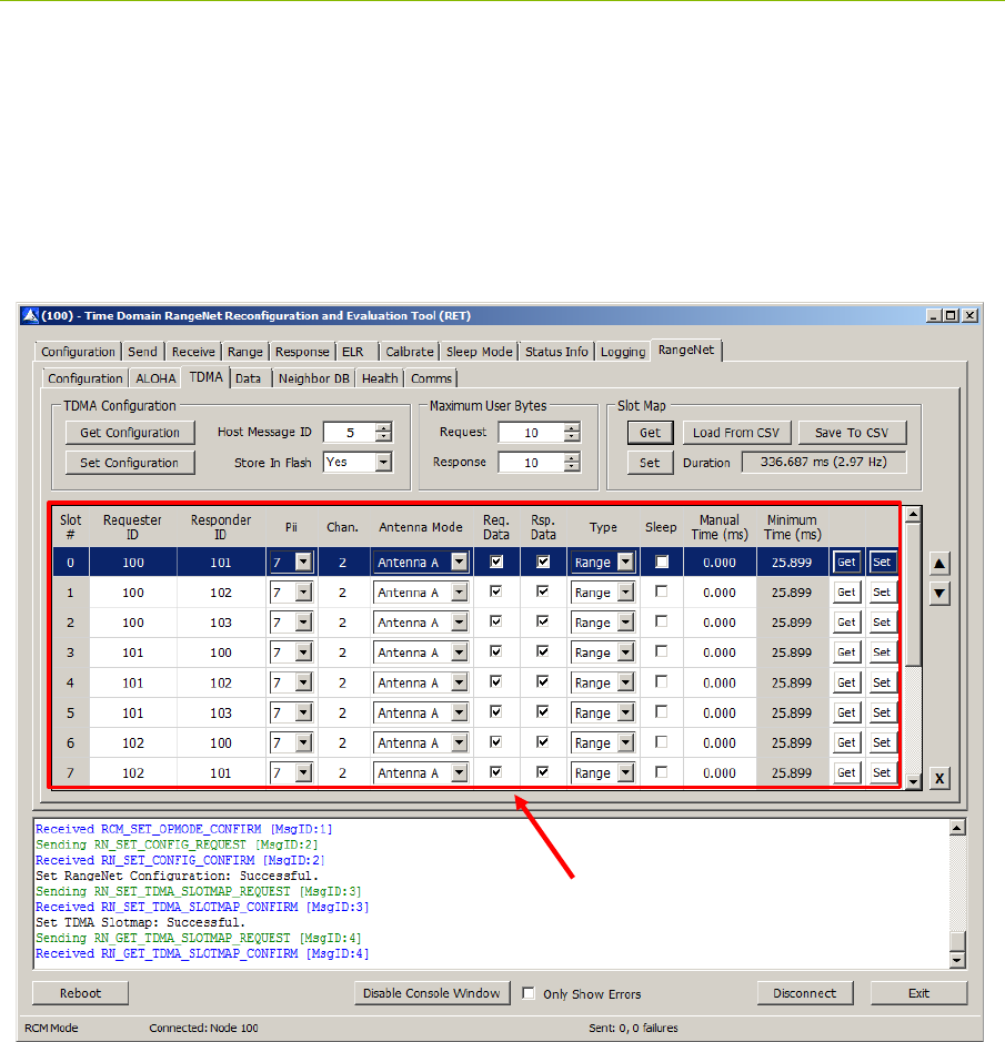
If the TDMA protocol is used, then the user can define a slot map that provides each radio
with an indication of when and to whom and with what parameters it should communicate.
An example slot map is shown below in Figure 5. The slot map shown is for a system of 4
nodes (100, 101, 102, and 103) in which 100 and 101 range to each of the other three and 102
ranges to 100 and 101.
Fig. 5: Representative RangeNet slot map
Maintaining system synchronization is the responsibility of the P440 processor and it does so
with an accuracy of 1 μs.
Because the P440 supports multiple communications channels, it is possible to operate either
the ALOHA or TDMA protocol with a CDMA overlay.
Because the P440 network schedules range requests, it avoids the overhead of Host to P440
communications and can therefore run at a higher ranging rate.
The P440 network maintains a neighbor database. Besides noting all of the members of the
network and their ranges, this database also contains a large body of statistics and other
useful information. For example, the database includes SNR, approach velocity, effective
ranging rate, and signal quality.
TDMA Slotmap

P440 Data Sheet / User Guide DRAFT 15
The network also takes advantage of two features available with simple ranging applications,
Echo Last Range (ELR) and Coarse Range Estimate (CRE), but which find special utility
when used in a network. ELR takes advantage of the fact that all units can receive any
transmission. Whenever a unit requests a range from a particular unit, it also transmits the
last successful range measurement and node number of the corresponding unit. This
information is effectively broadcast to all units in the area. This mechanism therefore
distributes network range information throughout the units in the system.
CREs take similar advantage of the broadcast nature of transmission. When a unit receives a
transmission it will automatically generate a waveform scan and measure the strength of the
first arriving energy. This yields a number similar to RSSI, but which is different in two
ways. First, the strength measured is proportional to the strength of the first arriving energy
and not, as in the case of RSSI, the peak strength of any signal. Second, while RSSI is rarely
if ever calibrated, the CREs are calibrated based on the last time the unit successfully
completed a TW-TOF range measurement with the target unit. While the accuracy of a CRE
does not compare with the accuracy of the TW-TOF measurement, its level of accuracy is
frequently good enough to be useful and it has the added benefit of expanding the network
knowledge without incurring any cost.
While these are all powerful network tools, the complexity inherent in this richness can make it
difficult to visualize and operate through just the API. The RangeNet GUI fills this gap. Not only
does it allow the user to configure the system, but it also provides a means for easily maintaining
different configurations, monitoring results, evaluating the performance of individual links in the
network, and monitoring the neighbor database. For example, RangeNet allows the user to:
Define all types of configuration information (including TDMA slot map, ranging
configuration details, ALOHA setup information, neighbor database characteristics),
download it to the P440, store that configuration to disk, and recover from disk any given
configuration.
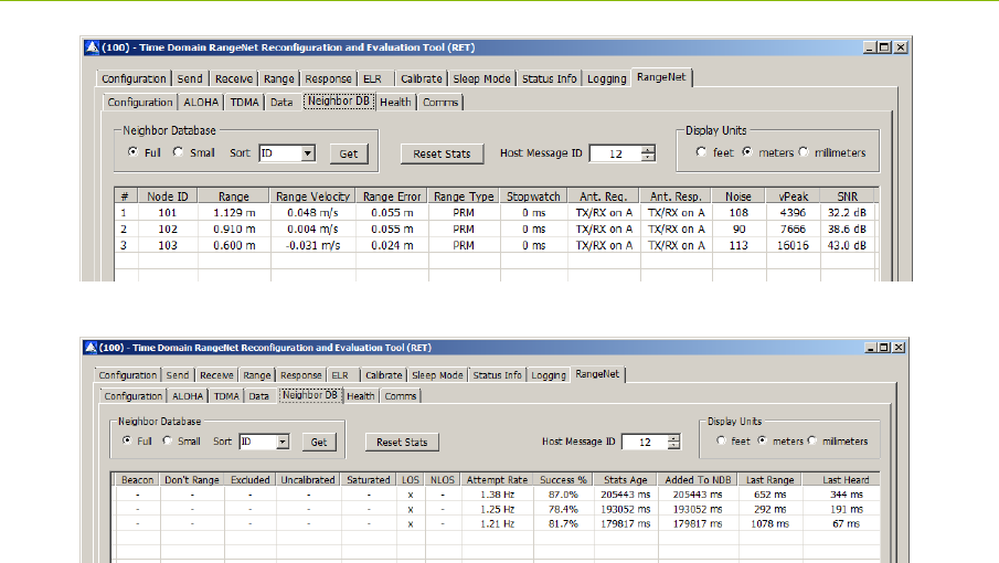
Monitor the database at whatever update rate the user finds useful. Figure 6 illustrates the
database from a 4-node system. Note the extent and volume of statistics maintained in the
database. (For details on the meaning of specific fields, refer to the RangeNet User Guide.)
Send, receive, and display data.
Display waveform scans associated with a particular link.
16 DRAFT P440 Data Sheet / User Guide
Fig. 6: Representative neighbor database of a 4-node system
2.4.3 Monostatic Radar with MRM RET
The Monostatic Radar API allows the user to configure the radar parameters, transmit pulses, and
measure radar returns. Configuration parameters include the following:
Communication channel
Transmit antenna configuration
Transmit power
The number of pulses that will be integrated to form a measurement
The desired duration of the received RF scan
This final parameter warrants discussion. The user can define what portion of the radar return should
be measured and reported. Furthermore, that portion does not need to be continuous or taken at the
same integration. For example, it is possible to measure the radar return corresponding to the
distance:
From the antenna to 10 meters
From 10 to 20 meters from the antenna
From 10 to 20 meters, from 30 to 40 meters, and from 50 to 55 meters
From 10 to 20 meters with integration of 256:1 and 40 to 50 meters with integration of
2048:1
The API also allows the user to define a rate at which the radar returns are generated. Furthermore,
these scans are coherent both in radar fast time and in radar slow time. With the use of a Hilbert
transform the radar returns can be post-processed to generate I and Q data streams.
P440 Data Sheet / User Guide DRAFT 17
The MRM RET GUI allows the user to:
Define all of the configuration parameters, download them to the P440, and save and retrieve
configurations from disk
Initiate radar transmissions
Collect, display, and log received data to disk
Furthermore, the MRM RET GUI has an associated task which will also:
Bandpass the received data
Motion filter the data
Detection filter the data
Report detections as well as the first arriving detection
This filtering task provides basic motion filter functionality and allows the user to tune the filter
constants. If desired, the user can also log all of this information with the raw data.
It should be noted that these filters are very general in nature and are not optimized for any particular
application. They are offered to the system developer as an example and the source code for the
filters can be found in the MRM RET User Guide.
The MRM RET GUI and associated sample code allow the user to exercise the P440 in a number of
important ways. Consider the following three examples:
Example 1 - I/Q Doppler processing: MATLAB Sample Application #3 allows the user to exercise
several radar modes. One mode of operation involves measuring the radar return from a moving
target and then using I/Q Doppler processing to produce a plot of a Range vs. Doppler shift. An
example plot is shown in Figure 7.
Fig. 7: Range vs Doppler shift from an approaching target
2
5
-30
-40
4
3
Range (m)
20
-20 -10 30
0
Doppler Shift (Hz)
10
18 DRAFT P440 Data Sheet / User Guide
Example 2 - SAR imaging: Undergraduates at the University of Alabama in Huntsville (UAH) used
the radar and a stepper motor to create a synthetic aperture radar (SAR) image of a collection of
aluminum soda cans arranged to form the initials of the university. The results are shown in Figure
8:
Fig. 8: SAR image of soda cans arranged to form the letters UAH
A copy of their project can be found on the Time Domain website at the following link:
http://www.timedomain.com/UAH%20Senior%20Project%20-%20Final%20Presentation%20V4.pdf
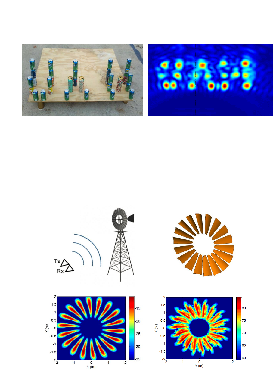
Example 3 – ISAR imaging: a team at the University of Texas (Austin) used the radar to build an
inverse synthetic aperture radar (ISAR) image of windmill blades. These results are shown in Figure
9:
Fig. 9: ISAR image of rotating windmill blades – (a) test setup (b) windmill blades (c)
blades as modelled (d) blades as imaged by the ISAR
a) b)
c) d)
P440 Data Sheet / User Guide DRAFT 19
A copy of their paper can be found on the Time Domain website at the following link:
http://www.timedomain.com/white-papers/Univ%20Texas%20Austin%20-
%20SAR%20Imaging%20of%20a%20Windmill.pdf
2.4.4 Bistatic Radar and Propagation with CAT (Channel Analysis Tool)
The CAT API and GUI allow the user to operate the P440 as either a bistatic radar or as a
communications propagation tool. This is easy because both applications are simply different ways
of viewing the same thing. Consider the waveform shown in Figure 10. A communications engineer
would look at this scan, point out the first arriving energy and comment that the multipath is due to
other reflectors in the channel. He might then use this waveform to compute the delay spread of the
channel and evaluate the impact of multipath on inter-symbol interference. A radar engineer would
look at this very same scan, point out the first arriving energy and comment that the multipath
reflections are due to a mix of fixed clutter and targets operating in the area. He might then use
Doppler processing or motion filters to separate the clutter from the targets.
Fig. 10: Captured waveforms can be used by either communications or radar engineers
Given this, it is best to ignore the application differences and focus on the functions provided by the
CAT API and GUI.
The API allows the user to transmit an arbitrary number of packets at a user-selectable
communications channel, over the antenna of choice, at a selected integration rate, at a selected
transmit power, and to receive packets from another unit. The receiver would then measure and
report the part of the waveform which the user is interested in evaluating. For example, the user
could request that the recorded waveform start 50 ns before the beginning of the pulse and end 145 ns
after the pulse (as shown in Figure 10). Note that this waveform was taken with a 61 ps resolution.
The CAT API also allows the user to specify other resolutions. For example, it is possible to take
waveforms at 4 ps intervals. Shown below in Figure 11 and Figure 12 are two waveforms. The only
difference between the two waveforms is that in one case the resolution was at 61 ps while the other
was taken at 4 ps.
20 DRAFT P440 Data Sheet / User Guide
Fig. 11: Waveform scan captured at 61 ps resolution
Fig. 12: Waveform scan captured at 4 ps resolution
Because transmissions will be received by any radio in the area, the system can have one transmitter
and many receivers. Depending on your point of view, this is either a spatially distributed multistatic
radar array or an excellent way to quickly collect data for an RF propagation model.
The API also has two final capabilities: (1) the user can send a fixed data pattern with a length of up
to 1000 bytes, and (2) the P440 will report the SNR of the signal.
The GUI allows the user to configure the units, initiate transmission, and then collect, display, and log
the data. The GUI will also report and log various statistics including packet error rate, bit error rate,
packets sent, bits sent, and SNR (Eb/No).
2.5 Networking: RangeNet vs. RangeNet Lite
RangeNet Lite is a node-limited version of RangeNet and is intended to allow users to evaluate and
test before considering licensing or purchasing the unrestricted version. RangeNet Lite is provided
with all Ranging and Localization Development Kits, as well as the PulsON Lab and MegaLab

P440 Data Sheet / User Guide DRAFT 21
packages. It is node-locked in that the Lite version will support all of the features of RangeNet as
long as the system size is limited to 10 nodes or less. More specifically, the first 10 nodes that join
the system will operate normally. They can join and leave the network normally, but the 11th unit
and all subsequent units will not be recognized by the system. These units will still operate but will
likely interfere with the first 10 units and significantly degrade network performance for the first 10
units.
For information on upgrading from RangeNet Lite, please contact Time Domain directly at
sales@timedomain.com.
2.6 Software Support
Time Domain is committed to maintaining full-featured software support for the hardware platforms.
We believe that the success of UWB will be largely determined not by the capability of the hardware
but by the richness of the software which drives the hardware. This includes improvements to both
the embedded software (where the basic functionality of the UWB technology can be changed) and
the API interface (where upper layers can be added).
For example, consider recent releases:
2010 – Ranging capability demonstrated with P400
2011 – Monostatic radar functionality added
2012 – Ranging performance enhanced
2013 – Channel analysis and bistatic / multistatic radar functionality added
2014 – RangeNet provides networking capability based on the ALOHA and
TDMA protocol support added
2015 – RangeNet Lite added
It is Time Domain’s intention to continue increasing the capability of UWB by adding new and
significant software functionality.
22 DRAFT P440 Data Sheet / User Guide
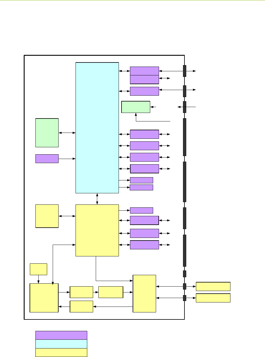
3 Hardware Block Diagram
This section provides and discusses at a high level the P440 functional hardware block diagram
shown in Figure 13. Additional detail on the various interfaces is provided in Section 4.
Fig. 13: P440 hardware functional block diagram
P400
FIFE
T/R Switch RF Port A
Filters &
LNA
Processor
FPGA
P440
UWB Antenna
RF Port B
Temp
UWB Antenna
Serial
USB USB Data Jack
Ethernet Jack
Ethernet
Can
J9
J5
Regulators
4.5-48Volts
Flash
and RAM
Memory
Flash
Memory
Blue LED
Green LED
Optional
Power Amp
Regulatory
Filter
16MHz
Osc
USB Power Jack
SPI (5)
3.3V GPIO (3)
3.3V GPIO (3)
J10 User Mezzanine
- VCC_Main
- Power Enable
- Fused Ground
- SPI (5)
- Serial
- CAN
- ARM 3.3V GPIO (2)
- FPGA 3.3V GPIO (2)
J11 Locking Connector
- VCC_Main
- Fused Ground
- SPI (5)
- Serial
- CAN
- ARM 3.3V GPIO (1)
- FPGA 3.3V GPIO (3)
Power Enable
Ethernet RMII
J13
J8 Ethernet Mezzanine
- Digital Ground
- Ethernet
- ARM 1.8V GPIO (2)
- Ext 16MHz CLK (reserved)
1.8V GPIO (2)
1.8V GPIO (2)
J6 Factory Mezzanine
- Digital Ground
- FPGA 1.8V GPIO (2)
- ARM 3.3V GPIO (1)
- Factory Reserved
Chassis Ground
VCC_Main
Green LED
UWB Components
Non-UWB Component
User Interface

P440 Data Sheet / User Guide DRAFT 23
The P440 requires less than 2.5 Watts from a DC supply that provides any voltage between 4.5 and
48 volts. This power can be provided through Time Domain’s standard external power supply, a
battery, or a user-supplied power source. Indicator lights provide operating status information.
The user can interface to the P440 through Ethernet, USB, SPI, Serial, or CAN. Ten GPIO pins are
available. If the SPI interface is not used, then these pins can be reassigned yielding an additional
five GPIOs for a total of 15.
In addition, the user can request that the P440 report the board temperature.
A variety of means have been provided to physically interface to the P440. These means include
USB connectors, an Ethernet RJ45 connector, a locking connector, and three mezzanine connectors.
See Section 4 for details. The mezzanine connectors are suitable for mating directly with a customer-
provided board. Mating mezzanine connectors can be ordered with a variety of mated heights,
thereby allowing the user to mount low profile devices on their carrier board underneath the P440.
See Section 5 for details.
Two SMA connectors are provided for antennas. Most ranging applications require only one antenna
but there are cases where two can provide additional functionality. Most radar applications require
two antennas.
The processor controls the UWB front end through a Digital Baseband FPGA interface. More
specifically, the FPGA acts as a digital baseband to configure and control Time Domain’s Fully
Integrated Front End (FIFE) UWB ASIC such that it is possible to transmit and receive packets to
measure range and to send/receive data.
There are four other items of note concerning the RF section:
The FIFE Pulser is provided with a variable attenuator that allows the user to reduce the
transmit power by approximately 20 dB below the regulatory limit. The exact amount or
reduction will vary a bit from unit to unit.
The T/R switch supports several configurations: Transmit/Receive on Port A,
Transmit/Receive on Port B, Transmit on A and Receive on B, and Transmit on B and
Receive on A.
The Receive chain has a series of gain stages and band pass filters.
An optional power amplifier can be provided to boost the transmitted signal power by up to
10 dB. Additional details are provided in Section 4 – Electrical Interfaces. This option is
intended for experimentation and evaluation only. Using it for any other purpose will exceed
regulatory limits in the US. Using the power amplifier in other countries, even for
experimentation, may require special permission.
24 DRAFT P440 Data Sheet / User Guide
4 Electrical Interfaces
This section provides a detailed description of the various P440 electrical interfaces. A standard P440
has the following connections:
Two antenna ports
Communications via Low Speed Serial, USB 2.0, Ethernet, CAN, SPI
Connections for up to 15 GPIO pins
Connections for power (4.5 to 48V), Ground, and Chassis Ground
There are also five indicator LEDs, three on the board and two on the RJ45 jack.
The physical interface to Communications, GPIO, and Power are through a mix of connectors (see
Figure 14) including the following:
Three mezzanine connectors
One locking connector
One Ethernet RJ45 connector
Two USB connectors (one power-only, one for data-only)
One 0.1” DIP header
This arrangement provides the user with a great deal of flexibility. However, some users may prefer
a reduced set of interfaces. In this case, it is possible to no-load undesired components. Doing so
saves a bit of cost and minimizes the board footprint. (Such configurations are possible but not
standard and should only be considered for large volume applications of >1000 units. For further
details, contact Time Domain directly at sales@timedomain.com.) For standard optional
configurations see Section 10 – Configuration and Ordering Information.
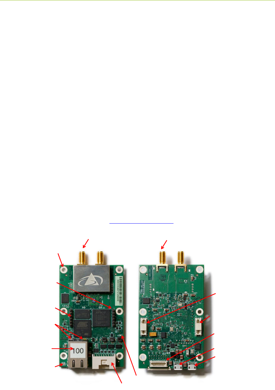
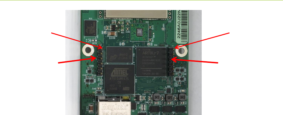
Fig. 14: Top and Bottom assembly drawing of the P440 highlighting key interfaces
Top Side Bottom Side
Chassis
Ground
J11- Locking
Ethernet Jack
with Kit
IP Address/Node Label
J10- User Mezzanine
J13- USB Power
J5- USB Data
J8- Ethernet Mezzanine
J6- Factory Mezzanine
J7 –User
Serial Header
J4 - Reserved
Header
Port A Port B
UWB LEDs
FPGA LED
Ethernet
LEDs

P440 Data Sheet / User Guide DRAFT 25
Finally, the physical interface for the Chassis Ground is through the designated mounting screw hole
shown in Figure 14. (For additional details, see Section 4.3 – Powering and Grounding the Unit).
4.1 Connecting to the P440
The user can connect to the P440 in a number of different ways. For example, it is possible to:
Connect directly to the USB or Ethernet connectors
Build a special purpose cable and connect through the locking connector
Mount the P440 on a carrier board and communicate through one or more mezzanine
connectors
The following are examples of the electrical connections:
Option 1: USB. The user can connect to the board via the USB Data jack (J5) and power
the unit through the USB Power jack (J13).
Option 2: Ethernet. The user can connect to the P440 via the Ethernet RJ45 jack and then
power the unit through the USB Power jack (J13). Details on how the Ethernet IP address is
assigned can be found in Section 4.4.5 – Ethernet and IP Addressing.
Option 3: Locking Connector. The user can use the locking connector to connect via SPI,
User Serial, or CAN. This connector also provides power and ground. Details on the
pinouts for the locking connector and the part number for mating connector are provided in
the following section.
Option 4: User Mezzanine Connector. The User Mezzanine connector supports SPI, User
Serial, and CAN. It also provides power and ground. See the following section for details.
Option 5: Ethernet Mezzanine Connector. This connector provides power, ground, and all
of the Ethernet MAC signal lines necessary to communicate with the unit. However this
requires that the user provide an Ethernet PHY chip on a carrier board.
Several of these connection approaches offer access to the GPIO pins. See the following section for
details.
4.2 Connector Pinouts
The pinouts of the various connectors are shown in Figures 15a, 15b, 15c, 15d, and 15e. The
numbering convention that defines pin numbers with connector pins is shown on Figures 15f and
15g.
All signal lines are provided with Electrostatic Discharge (ESD) protection (+/- 8 kV contact
discharge and +/-15 kV air-gap discharge). The signal line voltage levels are 3.3 Vdc, 1.8 Vdc, or (in
the case of CAN) are differential. These inputs are not tolerant to other voltages. Overdriving these
lines with too large a voltage or requiring them to source too much current will cause damage to the
P440. Please take care to avoid damage. Not only will this compromise or damage the performance
of the system but this class of damage is not covered by warranty.
Some of the mezzanine connector pins are marked as “Reserved.” The function of these pins may
change with time. If the user intends to mount the P440 on a carrier board, then it is advisable to
connect any pin marked “Reserved” to a landing point but to NOT connect the landing point to any
other trace on the carrier board.
The part numbers of all of the connectors and their mates can be found in Section 5 – Mechanicals.

26 DRAFT P440 Data Sheet / User Guide
Finally, it may be useful to clarify the directions associated with the Serial transmit (TX) and receive
(RX) lines. “User Serial TX” means transmitted by the P440 to the Host. “User Serial RX” means
received by the P440 from the Host. All user serial lines operate at 3.3v.
Fig. 15a: J11 - Locking connector
Fig. 15b: J10 – User Mezzanine connector
SPI users should take note that the SPI interrupt line is pin 4 on the User Mezzanine and pin 2 on the
locking connector.
Pin Name Function
1 SPI_MOSI SPI Master Out Slave In
2 SPI_INT SPI interrupt
3 SPI_MISO SPI Master In Slave Out
4 FPGA_GPIO_1_3.3V FPGA General Purpose IO #1, 3.3VDC
5 Fused_GND Ground
6 FPGA_GPIO_2_3.3V FPGA General Purpose IO #2, 3.3VDC
7 SPI_CLK SPI Clock
8 Fused_GND Ground
9 SPI_CS SPI Chip Select
10 User_Serial_TX User serial transmit
11 ARM_GPIO_0_3.3V ARM General Purpose IO #3, 3.3VDC
12 User_Serial_RX User serial receive
13 Fused_GND Ground
14 Fused_GND Ground
15 FPGA_GPIO_3_3.3V FPGA General Purpose IO #3, 3.3VDC
16 CAN_HIGH CAN differential high
17 VCC_Main Input power (4.5 to 48v)
18 CAN_LOW CAN differential low
Pin Name Function
1 SPI_MOSI SPI Master Out, Slave In
2Fused_GND Ground
3 SPI_MISO SPI Master In, Slave Out
4 SPI_INT SPI interrupt
5Fused_GND Ground
6 FPGA_GPIO_1_3.3V FPGA General Purpose IO #1, 3.3VDC
7 SPI_CLK SPI clock
8 FPGA_GPIO_2_3.3V FPGA General Purpose IO #2, 3.3VDC
9 SPI_CS SPI Chip Select
10 Fused_GND Ground
11 ARM_GPIO_0_3.3V ARM General Purpose IO #0, 3.3VDC
12 User_Serial_TX User serial transmit
13 Fused_GND Ground
14 User_Serial_Rx User serial receive
15 ARM_GPIO_1_3.3V ARM General Purpose IO #1, 3.3VDC
16 Fused_GND Ground
17 Power_Enable_H
Signal line to enable/disable on-board
regulators. This allows the user to turn power
to the board on and off with a single digital
control line. 0-2.1Vdc = off, 2.1Vdc to
VCC_Main = on
18 CAN_HIGH CAN differential high
19 Fused_GND Ground
20 CAN_LOW CAN differential low
21 VCC_MAIN Input power (4.5 to 48v)

P440 Data Sheet / User Guide DRAFT 27
Fig. 15c: J8 – Ethernet Mezzanine connector
Fig. 15d: J6 – Factory Mezzanine connector
The Factory Mezzanine connector has a number of GPIO pins and grounds which the user is free to
use. However the remaining lines are NOT available for use. All of these lines are active and are
used by the factory to test the unit as it moves through production. This connector can be used by the
Pin Name Function
1 Digital_GND Digital Ground
2 E_Rx1 Ethernet Rx1
3 E_Rxer Ethernet Rxer
4 E_TxEn Ethernet TxEn
5 E_Tx0 Ethernet Tx0
6 Digital_GND Digital Ground
7 E_Tx1 Ethernet Tx1
8 E_CrsDv Ethernet CrsDv
9 Digital_GND Digital Ground
10 E_TxCk Ethernet TxCk
11 E_Rx0 Ethernet Rx0
12 Digital_GND Digital Ground
13 E_MDIO Ethernet MDIO
14 E_MDC Ethernet MDC
15 Digital_GND Digital Ground
16 Digital_GND Digital Ground
17 ARM_GPIO_0_1.8V ARM General Purpose IO #0, 1.8VDC
18 ARM_GPIO_1_1.8V ARM General Purpose IO #1, 1.8VDC
19 Digital_GND Digital Ground
20 Digital_GND Digital Ground
21 Ext_16MHz_In Reserved
Pin Name Function
1 Reserved
2 Reserved
3 Reserved
4 Reserved
5 Digital_GND Digital Ground
6 Digital_GND Digital Ground
7 Reserved
8 Reserved
9 Reserved
10 Reserved
11 Digital_GND Digital Ground
12 FPGA_GPIO_1_1.8V FPGA General Purpose IO # 1, 1.8VDC
13 Reserved
14 Reserved
15 Reserved
16 Reserved
17 Reserved
18 FPGA_GPIO_0_1.8V FPGA General Purpose IO #0, 1.8VDC
19 Reserved
20 ARM_GPIO_2_3.3V ARM General Purpose IO #2, 3.3VDC
21 Digital_GND Digital Ground
28 DRAFT P440 Data Sheet / User Guide
customer but it is critical that the reserved pins should never be connected to any signal, ground, or
power lines. This can result in extreme damage to the unit.
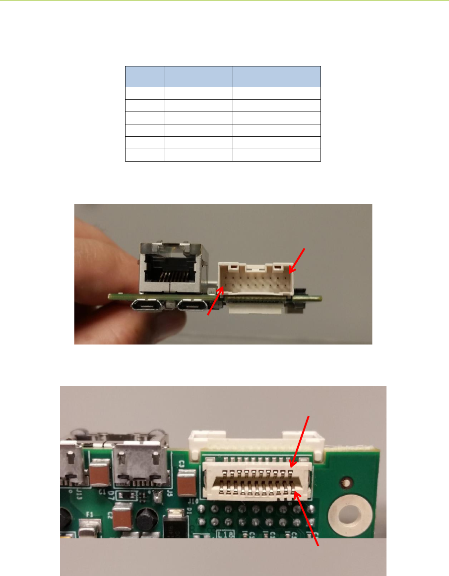
Fig. 15e: J7 – User Serial 0.1” Header
Fig. 15f: Locking connector pinouts
Fig. 15g: J10 Mezzanine connector pinouts
Pin Name Function
1 Digital_GND Digital ground
2 No Connection Reserved
3 No Connection Reserved
4 User_Serial_RX User serial receive
5 User_Serial_TX User serial transmit
6 No Connection Reserved
17 15 13 11 9 7 5 3 1
18 16 14 12 10 8 6 4 2
20 18 16 14 12 10 8 6 4 2
21 19 17 15 13 11 9 7 5 3 1
P440 Data Sheet / User Guide DRAFT 29
Fig. 15h: User Serial pinouts
4.3 Powering and Grounding the Unit
4.3.1 Powering the P440 through the USB Power Jack vs Locking &
Mezzanine Connectors
The P440 is provided in Development Kits or Labs as a “Kit Radio” and individually as an “Industrial
Module.” The difference between the two is a configuration option. P440s provided as Kit Radios
are powered through the USB Power jack (J13). P440s provided as Industrial Modules can be
powered either through the Locking connector (J11) or the User Mezzanine connector (J10). Kit
Radios cannot be powered through the Locking or User Mezzanine connectors and Industrial
Modules cannot be powered though the USB Power jack.
This is a safety feature intended to insure that the user cannot accidentally connect power through the
Locking connector at voltages as high as 48 volts while simultaneously connecting power through the
USB Power jack at 5 volts. Allowing this to happen would put both the P440 and any computer
connected to the USB Data jack at risk of severe damage.
4.3.2 Reverse polarity protection
The power input (VCC_Main) is reverse polarity-protected and can be driven by any voltage between
4.5 and 48 volts.
4.3.3 Two means of Powering the P440
There are two techniques for supplying power to the P440. One can connect and disconnect the
power connectors or one can power the board continuously and use the Power_Enable_H pin on the
J10 User Mezzanine connector to turn on and off the P440 main power regulators. This capability
gives the user the opportunity to do a hard reboot of the board without needing to physically break a
connection.
J7 –User
Serial Header J4 - Reserved
Header
Pin 1
Pin 1

30 DRAFT P440 Data Sheet / User Guide
4.3.4 Chassis Ground
The P440 is provided with a chassis ground. Each of the six mounting holes is copper plated on the
top, bottom, and inside of the hole. The mounting holes are not covered with silk screen. These
holes are not connected to any ground planes or signals of any sort. The one exception to this rule is
connected to Digital_Ground through the parallel combination of a 0.01uF capacitor and 1.0 MOhm
resistor. The position of this hole is shown in Figure 14.
4.3.5 Fused_Ground and Digital_Ground
Connecting power to the board is relatively straightforward, but there is subtlety associated with the
ground. The subtlety is associated with the difference between Fused_Ground and Digital_ Ground.
As a general rule, it is best to connect to the Fused_Ground and avoid the Digital_Ground. This is
not a concern for developers who will typically interface to the P440 using either the Ethernet or the
USB connectors and power the unit through the USB Power jack. It is also not a concern when the
P440 is integrated into a final product through either the Locking Connector or the User Mezzanine
connector.
It might be an issue if the user intends to connect to either the Ethernet Mezzanine connector or GPIO
pins on the Factory Mezzanine connector. Normally the Fused_Ground is the preferred connection,
but there are some cases in which it might be better to connect to the Digital_Ground. Customers
intending to make use of these connections should contact the factory and discuss the issue in more
detail.
4.3.6 P440 Power Requirements
When operating continuously, a standard P440 requires approximately 2 watts. However, two other
factors need to be considered. First the power consumption of electronics will vary with temperature.
Second, the efficiency of the regulators declines with increasing input voltage. Basically, the
regulators have been designed for optimum efficiency when operated at 5 volts.
Figure 16 indicates how the power consumed from a 5 volt supply changes with temperature for two
different P440s. The temperatures shown were measured by the onboard temperature sensor. Note
that the units require a bit more power when operated as a receiver than as a transmitter. These
results are typical.
Fig. 16: Power Consumption as a function of board temperature for two representative P440s
(red and blue) when operated as a transmitter (left) and as a receiver (right)
Figure 17 indicates how the efficiency of the onboard regulators changes with input voltage. This
data was measured while the P440 was transmitting and the onboard temperature sensor indicated a
temperature of 37°C.
Power Consumption (Watts)
Temp (Deg C)
Power Consumption (Watts)
Temp (Deg C)
1.0
1.2
1.4
1.6
1.8
2.0
2.2
2.4
2.6
2.8
3.0
-40 -20 0 20 40 60 80 100
1.0
1.2
1.4
1.6
1.8
2.0
2.2
2.4
2.6
2.8
3.0
-40 -20 0 20 40 60 80 100

P440 Data Sheet / User Guide DRAFT 31
Fig. 17: Increase in P440 power consumption with increased supply voltage
When selecting a power supply to drive the P440, the system designer should take both of these
factors into consideration and apply a safety margin. For example, a P440 which is intended to
operate at 5 volts and at a maximum board temperature of 85°C should be provided with at least 2.8
watts. If the same system was operated at 48 volts and 85°C, then the P440 should be provided with
at least 144% more power or 4.032 watts. These values do not include any additional safety margin
which the application might require.
The P440 also has an idle state during which it is neither transmitting nor receiving. In this idle state
the power consumption is reduced by approximately 30%.
4.4 Host to P440 Interface Options
The P440 supports five different host interfaces: USB, Serial, SPI, Ethernet, and CAN. This wide
choice of interfaces provides the user with the freedom to experiment with and to optimize the means
by which the overall system (P440 plus the user Host) communicates for their specific application.
The characteristics of these interfaces are summarized below. For information on pin assignments see
Section 4.2 – Connector Pinouts.
Supply
(Volts)
Current
(ma)
Power
Consumption
(Watts)
Power increase
due to loss in
efficiency
5.06 395 1.999 100%
5.95 337 2.005 100%
7.02 287 2.015 101%
8.04 253 2.034 102%
9.07 225 2.041 102%
10.04 205 2.058 103%
12.16 171 2.079 104%
14.07 150 2.111 106%
16.04 134 2.149 108%
18.03 121 2.182 109%
20.07 111 2.228 111%
22.09 102 2.253 113%
24.01 95 2.281 114%
26.05 89 2.318 116%
28.07 84 2.358 118%
30.06 80 2.405 120%
32.15 76 2.443 122%
34.12 73 2.491 125%
36.05 70 2.524 126%
38.07 68 2.589 130%
40.08 66 2.645 132%
42.03 64 2.690 135%
44.07 62 2.732 137%
46.08 61 2.811 141%
48.03 60 2.882 144%

32 DRAFT P440 Data Sheet / User Guide
The protocol used to communicate with the P440 is fully defined in the various Time Domain API
Specifications, various C and MATLAB examples, and in the document “Using the USB and Serial
specifications. All of these resources are provided on the delivery disks and are also available on the
Time Domain website, www.timedomain.com.
4.4.1 USB 2.0 High Speed Device
The P440 supports USB 2.0 High Speed Device connection through the USB Data microUSB jack
(J5). When connecting through J5 it is important to remember that this jack only provides the data
communications lines to the P440. To power the board, the user should apply power to the board
either through the USB Power microUSB jack (J13), through the locking connector (J11) or through
pin 21 on the User Mezzanine connector.
The maximum data rate for the USB is 480 Mbps. However, the maximum effective throughput will
be limited by many factors, including the speed of the Host computer, the specific implementation of
the USB driver, processing overhead at the P440, and processor overhead at the Host computer.
4.4.2 User Serial
The User Serial interface is RS-232 Universal Asynchronous Receiver/Transmitter (UART) Serial
operating at 3.3V TTL logic levels. The maximum speed of the interface is 115.2 kbps. Lower rates
of 9.6, 19.2, 38.4, and 57.6 kbps are also supported. The default rate is 115.2 kbps.
However, the maximum rate is largely a function of the ability of the system to drive the cable
capacitance. If a shorter cable is used or if the user provides an external line driver, then the
communications rate can be increased by factors of 2 up to 921.6 kbps. Operation at these higher
ranges is also limited by the serial interface circuit on the user-provided Host computer. The
maximum length of cable must be determined empirically. Time Domain has found that a cable
length of 1 foot (30 cm) will support the 460.8 kbps rate quite reliably.
User Serial is provided on the Locking connector (J11), the User Mezzanine connector (J10), and the
User Header (J7).
The Serial interface uses 3.3 volt logic. Do not connect 5 volt serial cables to the P440. In fact, do not
connect any serial cables that operate at greater than 3.3 volts. The increased voltage will physically
damage the P440.
4.4.3 SPI
The SPI interface is designed to operate at a maximum clock rate of 16.0 MHz with signals operating
at 3.3V TTL levels. The actual throughput of the link is limited by the various communications
overheads. However, transfer rates of 6-7 Mbps have been achieved using an un-optimized system.
The SPI port consists of five signals. Four of these are the typical SPI signals: CLK, CSn, MOSI, and
MISO, each with a 100k pull-up resistor to 3.3 V. The fifth signal (INT) is active-high and is used to
indicate that data exists in the slave output FIFO. The INT signal does not have a pull-up resistor and
is not driven during initial power-up. The signals are illustrated in Figure 18. The SPI slave RX and
TX FIFOs are 4k x 8.
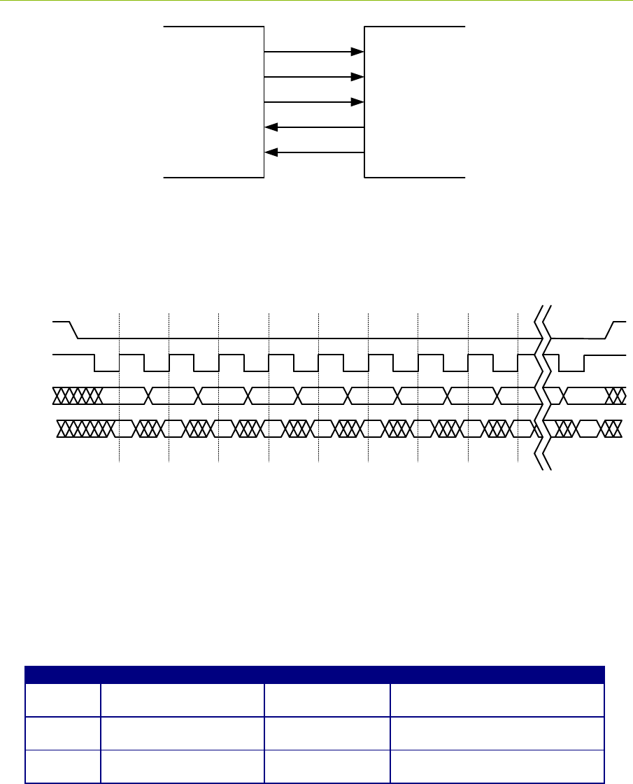
P440 Data Sheet / User Guide DRAFT 33
Fig. 18: SPI interconnect signals
The SPI port uses 8-bit bytes sent MSb first. The CLK idle state is high. The data is propagated on
the falling-edge (leading-edge) of clock and sampled on the rising-edge (trailing-edge) of clock as
shown below in Figure 19:
CSn
CLK
MOSI
MISO 76543210
Bit 7 Bit 6 Bit 5 Bit 4 Bit 3 Bit 2 Bit 1 Bit 0 Bit 7
7
Bit 0
0
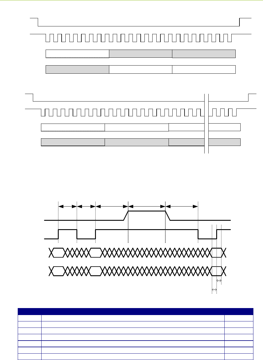
Fig. 19: Signaling timing diagram
The master drives the SPI chip-select low (CSn in above figure) and shifts an 8-bit command,
possibly followed by data. The first bit (MSb) of a command is always set. If the second bit is set,
then it is a read command, otherwise it is a write command. The commands are listed below in
Figure 20. The chip-select must stay active-low for the entire transaction, which is required to be on
8-bit boundaries. This and other timing diagrams are shown in Figure 21. Timing constraints are
shown in Figure 22.
Command
Function
Command Format
Response Format
0x80
Write to slave input FIFO
Command
followed by data
N/A
0xC0
Read from slave output
FIFO
Command
Slave output FIFO data
0xC2
Read slave output FIFO
byte count
Command
Two bytes: MSB followed by LSB
Fig. 20: SPI command structure
Master Slave
CLK
CSn
MOSI
MISO
INT
34 DRAFT P440 Data Sheet / User Guide
CSn
Clk
MOSI
MISO
8-bit command (0xC2)
Response Byte 1 (MSB) Response Byte 2 (LSB)
Don’t Care Don’t Care
Don’t Care
Read slave output FIFO byte count
CSn
Clk
MOSI
MISO
8-bit command Data Byte 1 Data Byte 2
Don’t Care Don’t Care
Don’t Care
Write to slave input FIFO
Data Byte N
Don’t Care
Fig. 21: Timing diagrams
CSn
CLK
MOSI
MISO
1 0 7
1 0 7
End of a SPI transaction Start of next SPI transaction
t1 t2 t3 t4 t5
t6
t7
Timing
Function
Minimum
t1
CLK high to CLK low (high pulse)
30 ns
t2
CLK low to CLK high (low pulse)
30 ns
t3
CLK rising-edge to CSn rising-edge (inactive)
50 ns
t4
CSn rising-edge (inactive) to CSn falling-edge (active) or time between transactions
60 ns
t5
CSn falling-edge (active) to CLK falling-edge
50 ns
t6
Data setup to CLK rising-edge
12 ns
t7
Data hold from CLK rising-edge
12 ns
Fig. 22: Timing constraints

P440 Data Sheet / User Guide DRAFT 35
4.4.4 Ethernet and IP Addressing
Ethernet 10/100 is provided either through the standard Ethernet RJ45 Jack or as Ethernet RMII
signal lines through the Ethernet Mezzanine Connector (J8). As such, the RMII signals cannot be
interfaced to directly. The user must provide a carrier board and an Ethernet PHY chip.
The communications rate through this interface is limited not only by the Ethernet 10/100 protocol
but also by the processing capability of the connected computer and various system overheads. For
example, when transferring radar scans, the typical maximum transfer rate using a low grade laptop
PC is approximately 2 Mbps. This transfer rate can be increased by a factor of four by using a faster
computer and by running C code unencumbered with displays and other user interface features. For
details, see the UWB radar sample C application, 150-0107D MRM Sample C Application. This
document can be found on the Time Domain website or on your release disk.
The IP address of a unit is assigned in one of two ways. If the P440 came as part of a Development
Kit or a PulsON Lab then the IP addresses will be set at the factory to 192.168.1.x, where “x” is
indicated on a label mounted on the P440’s RJ45 jack. If the P440 was ordered as an “Industrial
Module” then the IP address is set by the Dynamic Host Configuration Protocol (DHCP).
As a side note, the Node ID of the P440 is set in a similar fashion. If the P440 came as part of a Kit
then the Node ID will be set to “x.” If the P440 came as an Industrial Module, then the Node ID is set
at the factory and can be determined through the API or any of the GUIs provided with the system.
Instructions on how to connect to the P440 via Ethernet or change the IP address and Node ID are
provided in the following document: 320-0328 Connecting to P440 with Ethernet.
4.4.5 CAN
The CAN interface is provided with a TI SN65HVD231 CAN line driver. That driver provides a 5
volt differential signal. For additional details on the driver, a link is provided to the TI part. The
maximum data rate is 1 Mbps. http://www.ti.com/lit/ds/symlink/sn65hvd231.pdf
Time Domain’s application note 320-0326 CAN Interface Application Note provides additional
information on the software interface. This document is available on the Time Domain website.
4.5 GPIO
The P440 has fifteen user-definable general purpose input/output (GPIO) pins. Most of these pins
operate on 3.3 Vdc but there are several that operate at 1.8 Vdc. Approximately half come from the
ARM processor and the remaining ones are connected to the FPGA. These pins can be defined as
inputs, outputs, or as having a special function. The SPI pins are special function pins. If the user
chooses not to use the SPI interface, then the SPI pins can be reallocated for general use. The state
and direction of these pins are controlled through the software API.
The GPIO pins are not associated with a specific connector but are instead distributed through the
various connectors. Some GPIO pins are available from multiple connectors. Figure 23 lists the
various GPIO pins and their associated connector and pin number:

36 DRAFT P440 Data Sheet / User Guide
Fig. 23: GPIO and associated connector and pin locations
As of this date, there is currently no software support (i.e. API commands) for controlling the state of
the GPIOs. Similarly, the function of the SPI lines is currently fixed such that these lines can only be
used for SPI. Time Domain expects to provide expanded support for GPIOs in an upcoming
software release.
4.6 Antenna Ports
The P440 has two antenna ports, designated Port A and Port B. The connector used on each port is a
standard polarity female SMA connector (Digi-Key part number J801-ND). The two ports enable
single and dual antenna modes of operation.
An RF transfer switch on the P440 controls how the RF electronics are connected to the SMA
connector. Normal operation can be defined as:
1) Transmit/Receive on Port A
2) Transmit on A, Receive on B
3) Transmit/Receive on Port B
4) Transmit on B, Receive on A
RF energy generated by the UWB FIFE chip for radiation from the antenna will travel through the RF
transfer switch on its way to the antenna. In doing so, some of the energy will leak through the
J11 - Locking
1 SPI_MOSI
2 SPI_INT
3 SPI_MISO
7 SPI_CLK
9 SPI_CS
4 FPGA_GPIO_1_3.3V
6 FPGA_GPIO_2_3.3V
11 ARM_GPIO_0_3.3V
15 FPGA_GPIO_3_3.3V
J10 - User Mezzanine
1 SPI_MOSI
3 SPI_MISO
4 SPI_INT
6 FPGA_GPIO_1_3.3V
7 SPI_CLK
8 FPGA_GPIO_2_3.3V
9 SPI_CS
11 ARM_GPIO_0_3.3V
15 ARM_GPIO_1_3.3V
J8 - Ethernet Mezzanine
17 ARM_GPIO_0_1.8V
18 ARM_GPIO_1_1.8V
J6 - Factory Mezzanine
12 FPGA_GPIO_1_1.8V
18 FPGA_GPIO_0_1.8V
20 ARM_GPIO_2_3.3V
P440 Data Sheet / User Guide DRAFT 37
transfer switch directly into the receiver. In fact, energy received on the transmit antenna will also
leak through the transfer switch directly into the receiver. Normally this is not an issue, but the user
is advised that the isolation of the transfer switch is approximately 20 dB.
When connecting the port to an SMA cable or antenna, be careful not to overtighten the connection.
This can cause damage to the board. Beware of loose connections as these can degrade performance.
As long as the connectors are “finger-tight,” the system will work well. To insure an optimal
connection, the user should use a calibrated SMA torque wrench. These are generally available and
cost about $100.
The P440 is intended to be used with Time Domain’s Broadspec antenna. Using any other antenna
will require recertification to confirm compliance with the relevant emissions regulations. However,
it is possible to add passive extension cables between the antenna port and the antenna. Be aware that
using alternate UWB antennas, additional fixed attenuators, additional cabling and/or connectors will
change the RF time-of-flight electrical distance between the antenna port and the phase center of the
antenna. Failure to account for such changes will result in an offset or bias error in range
measurements.
4.7 RF Transmit and Receive Characteristics
Two versions of the P440 are available, one which is compliant with the US FCC transmission mask
as described in FCC Part 15.519 and one which is compliant with the EU ETSI EN 302 065 mask.
The major difference between these two versions is in the nature of the transmitted pulse. The band
edges on the EU mask are much more severe than for the FCC mask and as a result they require more
severe filtering. The EU waveform is therefore more narrow in frequency and longer in time
(contains more lobes) than the FCC version.
The receive characteristics of the EU and FCC devices are identical. Both devices use a pair of
identical bandpass filters arranged in a bandpass/LNA architecture. The characteristics of a single
bandpass filter are shown below in Figure 24.
Fig. 24: Characteristics of a single bandpass filter
4.8 Optional Power Amplifier
The P440 can be provided with an optional power amplifier which boosts the transit power by
approximately 16 db. In some cases, this can be valuable for evaluation or research activities.
However, this option is provided with two very important caveats.

38 DRAFT P440 Data Sheet / User Guide
First, operation with the power amp will exceed the transmit power of most (but not all) regulations in
most (but not all) countries. For example, in the US and Europe it will be very difficult to certify a
commercial product that makes use of this power amp.
Second, not only does the power amp increase the in-band transmit power but it also increases the
out-of-band transmit power. The increase in out-of-band power does not necessarily increase in a
linear fashion relative to the increase in-band power.
Units which are provided with an optional power amplifier will not carry an FCC certification mark.
While this option is available for experimentation and research, the user is responsible for ensuring
that its use is permitted by their country’s regulatory authorities.
4.9 Indicator Lights
The P440 is provided with five indicator LEDs. See Figure 14 for exact locations. The following is
an explanation of the LED functions.
Ethernet LEDs (located on the back of the RJ45 connector)
Green: Lit indicates operation at 100 Mbps, off means the link is operating at 10 Mbps.
Yellow: Lit indicates the link is available, flashing indicates activity, and off means no link.
UWB LEDs (located adjacent to the RJ45 connector)
Blue (Built in Test – BIT): flashing slowly (approximately 0.5 Hz) indicates that the unit is
operating normally. Flashing quickly (approximately 10 Hz) or solidly on or solidly off also
indicates a failure.
Green (UWB activity): Toggles (if off, turns on – if on, turns off) as follows:
o On initiation of a Range or Network Request packet transmission
o On initiation of a Range or Network Response packet transmission
o On initiation of a Range or Network Data packet transmission
o On initiation of a Network Beacon transmission
o On initiation of a CAT packet transmission
o On initiation of a CAT packet reception
o On completion of an MRM monostatic radar scan
FPGA LED (located on the same side but opposite edge from the UWB LEDs)
Green: Blinking indicates that the FPGA is loaded, acting as baseband, and is ready to
transmit or receive. Off indicates an FPGA fault or that the FPGA is in a low power sleep
mode.
The following is a description of the LED activity when the unit powers up. When power is applied
to the P440, the FPGA LED will begin blinking at approximately a 2 Hz rate. At the same time, the
Green UWB LED will turn off and the Blue LED will be on. The Blue LED will stay on for
approximately 5 seconds. This period is the boot time of the radio. Once the unit has successfully
booted, the Blue LED will blink approximately every 2 seconds. The Green UWB LED will blink
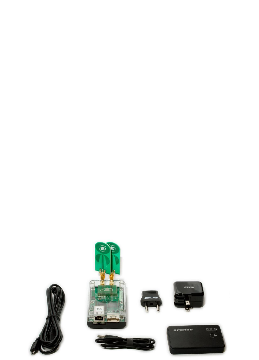
P440 Data Sheet / User Guide DRAFT 39
every time a packet is transmitted.
Any behavior other than what is described above should be considered to be a fault.
4.10 Heat Management
The P440 consumes approximately 2 watts. By way of reference this is approximately the same
power consumption as a typical cell phone. While this isn’t very much power, this energy is
sufficient to warm the board. In some extreme cases, this can cause issues. For example, if the board
is operated in a sealed enclosure, in a high ambient temperature, with solar heating then the resulting
thermal rise can raise the board temperature above its rated limit.
The P440 is equipped with a built in temperature sensor which will report the board temperature.
The user should monitor this temperature sensor and insure that the unit is not operated in excess of
the maximum rated temperature.
The following examples are provided to illustrate the effect of self heating on temperature rise.
Case 1: Ambient 23°C, bare board sitting on a table with light air circulation. Board Temp: 32°C
Case 2: Ambient 23°C, bare board sitting on a table in still air. Board Temp: 41°C
Case 3: Ambient 23°C, board mounted in Time Domain enclosure accessory. Board Temp: 47°C
4.11 Accessories
When the P440 is ordered as part of a Development Kit or Lab, it is provided with a number of
accessories. These accessories include: a custom plastic enclosure, a power supply, USB battery and
cabling and antennas. Ranging Kits are supplied with 1 antenna per P440 while Radar Kits and Labs
are provided with 2 antennas per P440. Units shipped outside the US are typically provided with a
power plug adapter to ensure compatibility with the user’s AC power plugs. This is illustrated in
Figure 25.
Fig. 25: P440 with full set of accessories
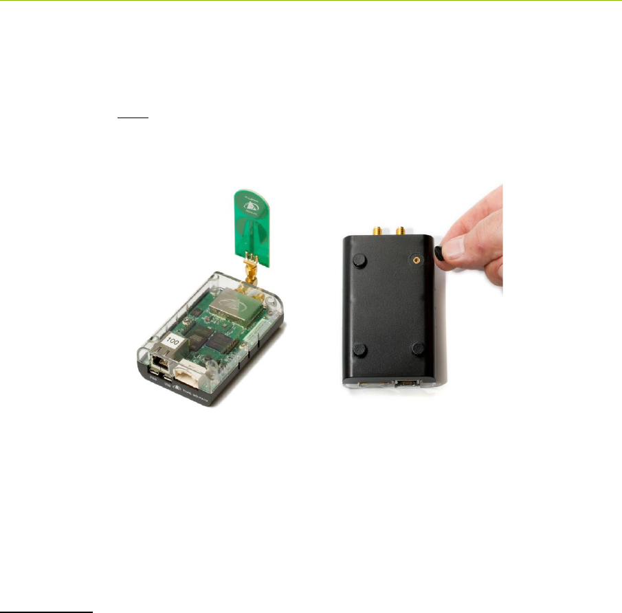
40 DRAFT P440 Data Sheet / User Guide
4.11.1 Enclosure
The enclosure is intended to provide a modest level of protection for the boards. The primary goal is
to avoid damage from light handling, accidental drops on the floor, coffee spills, and the like. The
enclosures also make it easy to safely and conveniently take measurements in buildings and outdoors.
The enclosures are NOT waterproof or rain proof. A photo of the enclosure is shown in Figure 26.
Note that underneath the enclosure are 4 rubber feet which conceal four 4-40 (not metric) mounting
holes. Those holes are suitable for attaching the unit to a fixed object.
Fig. 26: P440 in standard enclosure (left) and view of enclosure bottom showing feet and
mounting holes for 4-40 screw
4.11.2 Power Supply/Charger with Battery and Cables
P440s provided with Kits and Labs are powered through the USB Power jack. Time Domain also
provides each P440 with a USB Power Supply/battery charger, two USB cables (1.8 m and 15 cm)
and a 3000mAh USB battery.
Power supply: The power supply is intended for use with the standard North American wall plugs.
For units shipped outside North America, the power supply is also provided with an interface plug
(see Figure 27). Every attempt is made to provide an adapter compatible with the end user’s power
system, but this cannot be guaranteed. Please indicate your preference when ordering your
equipment.
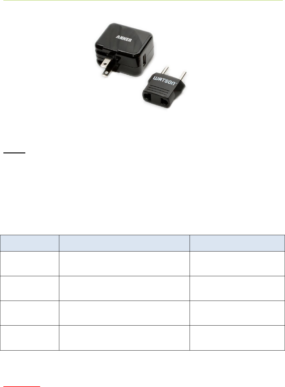
P440 Data Sheet / User Guide DRAFT 41
Fig. 27: USB Power Supply and interface plug
Cables: The 1.8 m (6 ft) cable is a standard USB cable and can be used to power the unit or
communicate through the USB data port. The 15 cm (6 in) cable is intended to connect the unit to
the USB battery but it can also support USB data communications.
In principle, there is nothing special about these components and they are almost universally
available. The user is free to provide substitutes and replacements for units that are lost or damaged.
While Time Domain does stock the USB battery all of these components are available on the web
from a variety of sources. Table 1 shown below provides source information for these components.
Where possible it includes specific suppliers and part numbers. Entering the product description into
your favorite internet search engine will lead you to any number of suppliers.
Description
Searchable description
Source and part number
USB battery
AFENDO 3000mah External Portable
Rechargeable Battery
6 ft/ 1.7 m USB
cable
6ft USB 2.0 A Male to Micro 5pin Male
28/28AWG Cable
Monoprice product number
12002
6 in /15 cm USB
cable
Premium USB to Micro USB Charge &
Sync Cable 0.5 ft –Black
Monoprice Product Number:
4868
Charger/supply
Anker 10W (2A) Home and Travel USB
Wall Charger Adapter
Table 1: Accessory source information
WARNING: In practice, USB devices are not provided with a uniform level of quality. The devices
listed above work well and are recommended. The same cannot be said about other USB devices.
Some suppliers of cables use undersized wiring that is so small that it is not capable of providing
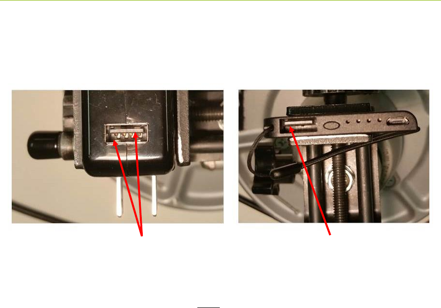
42 DRAFT P440 Data Sheet / User Guide
sufficient power to the P440s. Some batteries and power supplies have very poor connectors. These
connections are so flimsy that they provide power only intermittently. Consider the devices shown in
Figure 28. The connector on the left provides a high quality connection. The one on the right will
cause endless problems. Nothing will ruin a multiday measurement campaign more completely than
a few cheap and worthless USB cables and connections.
Fig. 28: Superior connections (left) and inadequate product (right)
When providing power from USB devices do NOT use USB extension cables. There is sufficient
voltage drop across these cables that they will not provide sufficient power to drive a P440.
Two sets of pins guarantee a good connection Nothing to insure a proper connection
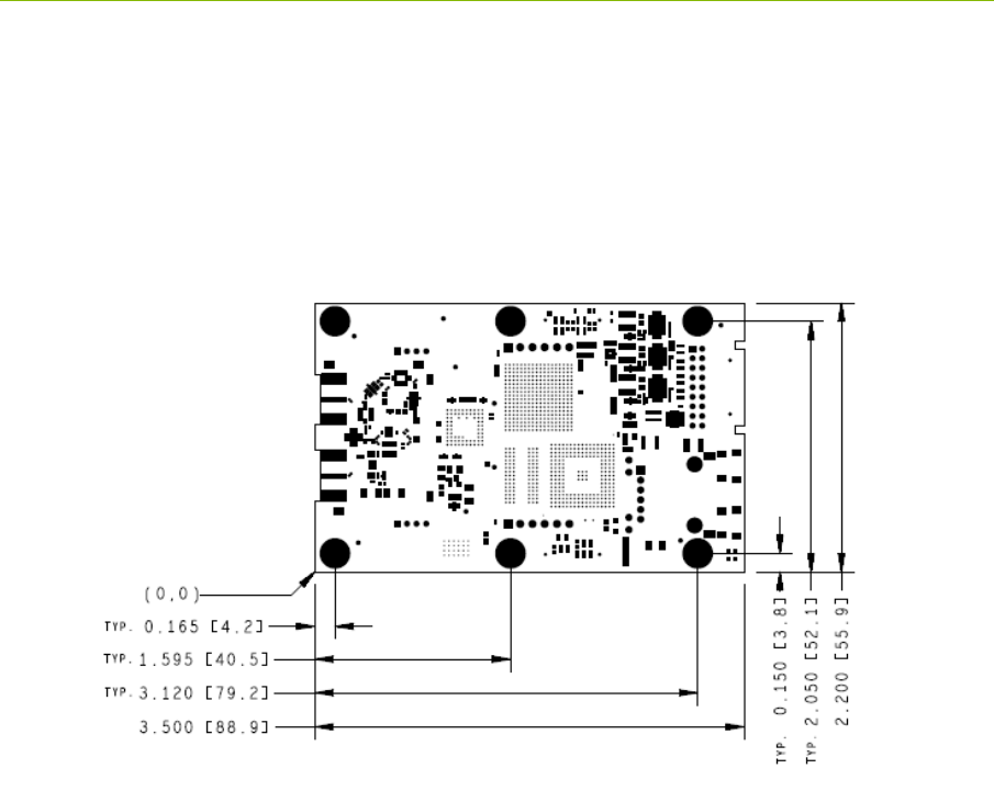
P440 Data Sheet / User Guide DRAFT 43
5 Mechanical Interface
Figures 29, 30, 31, 32, and 33 provide the information which defines the board size, the height of key
components, as well as the location and dimensions of all connectors. Dimensions are shown in
British Imperial units (inches). Dimensions shown in [brackets] are in metric (millimeters). Table 2
lists the part numbers of all connectors and their respective mating pair.
Fig. 29: P440 board dimensions
The six mounting holes have an inside diameter of 0.125 inches (3.175 mm) and are sized for a #4
screw. The pads have an outside diameter of 0.250 inches (6.35 mm). The minimum distance
between the center of the hole and the closest component or circuit trace is 0.140” (3.556 mm).
It is anticipated that the number of mounting holes, size of the holes and placement separations are
sufficient to satisfy most vibration requirements. Several customers have already satisfactorily tested
the vibration performance of the P440 in extremely challenging end applications.
The P440 board is built to IPC Class 2 standards. The tolerances associated with hole size and
centering are consistent with this standard.
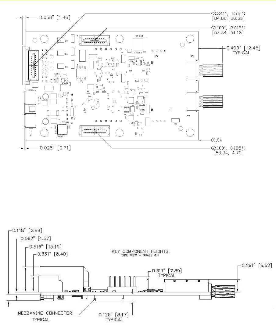
44 DRAFT P440 Data Sheet / User Guide
Fig. 30: Locations of Mezzanine connectors
Also shown in Figures 30 and 31 are all of the parts which extend out beyond the board dimensions.
This includes the RF SMA connectors, the Locking connector, the USB micro connectors, and the
RJ45 jack.
Fig. 31: Components which limit vertical height
When the P440 is mounted on a carrier board, the designer should be careful not to place any
components within 0.125” (3.17 mm) of the bottom of the board. This is a keep-out area and it is
reserved for components on the bottom side of the P440 board. Note that mating parts for the
mezzanine connectors are available with different lengths. By selecting a suitably tall mating
connector, the user can accommodate a wide variety of parts under the P440 without compromising
the keep-out area.
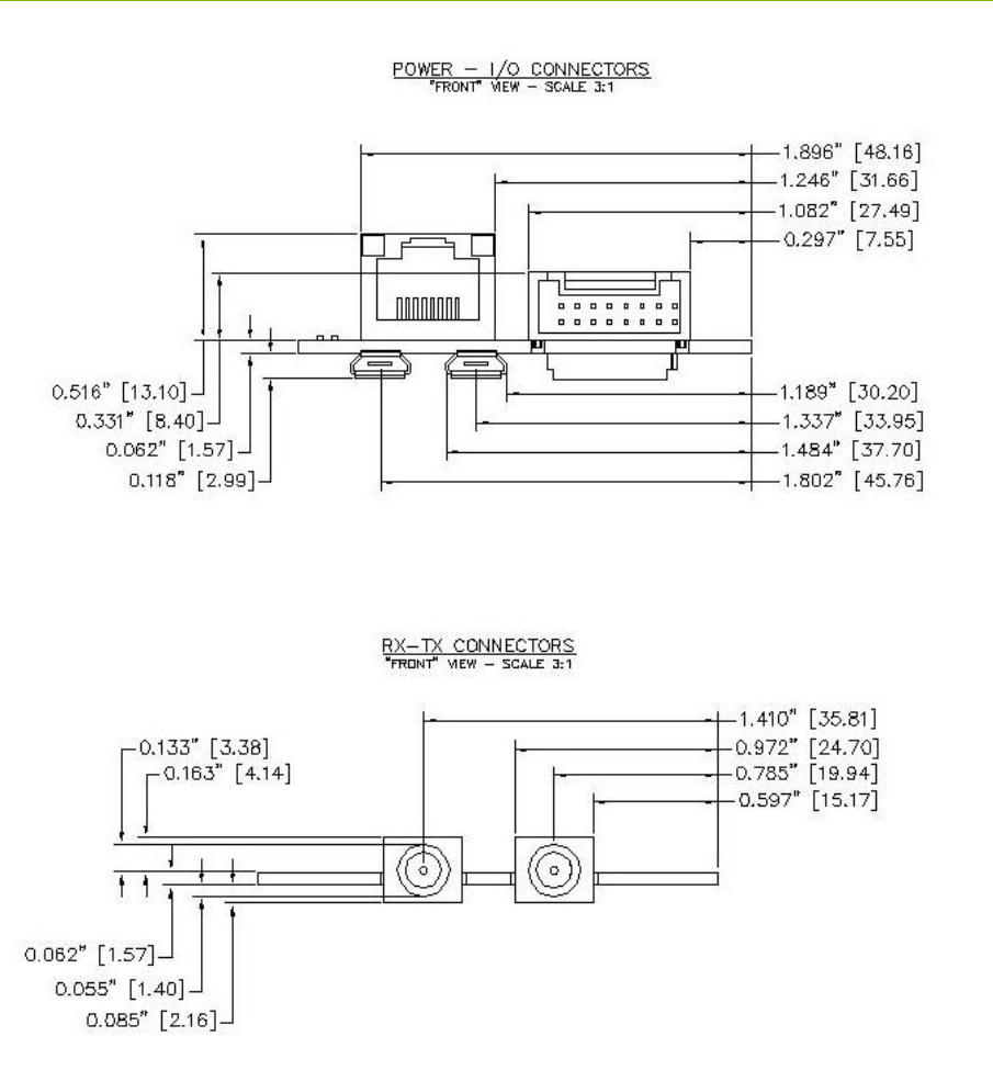
P440 Data Sheet / User Guide DRAFT 45
Fig. 32: Locations and dimensions of Power and I/O connectors at the rear of the P440
Fig. 33: Locations and dimensions of RF SMA connectors
The part numbers for the P440 connectors and their mating pair are shown in Table 2.

46 DRAFT P440 Data Sheet / User Guide
Table 2: Connector part numbers
* These are standard SMA, USB, or 0.1” headers, for which the user has a very large number of
choices. The right choice is application-specific. Fortunately, there is an option for almost every
conceivable application.
Name and Number P440 Connector Part Number Mating Connector Part Number
J2 - SMA Port A
Cinch Connectivity# 142-0701-871,
Digikey# J610-ND
Many different choices. *
J3 - SMA Port B
Cinch Connectivity# 142-0701-871,
Digikey# J610-ND
Many different choices. *
J5 - USB Data
FCI# 10103594-0001LF, Digikey# 609-
4050-1-ND
Many different choices. *
J6 - Factory Mezzanine
FCI# 91931-31121LF, Digikey# 609-
3520-2-ND
FCI# 91911-31321LF, Digikey# 609-
3424-2-ND
J7 - User Header
3M# 961106-6404-AR, Digikey#
3M9451-ND
Many different choices. *
J8 - Ethernet Mezzanine
FCI# 91931-31121LF, Digikey# 609-
3520-2-ND
FCI# 91911-31321LF, Digikey# 609-
3424-2-ND
J10 - User Mezzanine
FCI# 91931-31121LF, Digikey# 609-
3520-2-ND
FCI# 91911-31321LF, Digikey# 609-
3424-2-ND
J11 - Locking
JST Sales America: S18B-PUDSS-
1(LF)(SN), Digikey# 455-2490-ND
JST Sales America: PUDP-(18)V-S,
Digikey# 455-2473-ND
J13 - USB Power
FCI# 10103594-0001LF, Digikey# 609-
4050-1-ND
Many different choices. *

P440 Data Sheet / User Guide DRAFT 47
6 Technical Specifications
6.1 Summary of Key Performance Parameters
Table 3 summarizes the P440 specifications and key performance parameters.
P440 Specs
Value
Physical Parameters
Board Dimensions (without SMAs):
3.5 x 2.2 inches (89 x 56 mm)
Assembly height (bottom to top
connectors):
0.703 inches (17.9 mm)
Weight:
1.6 ounces (45 grams)
Storage Temperature:
-40oC to 85oC
Operating Temperature range:
-40oC to 85oC
Max allowable board temperature:
85oC (as reported by on board temp sensor)
Humidity:
Up to 95%, non-condensing
Vibration:
Designed to meet most vibration specs. Existing
customers have already tested the P440 for operation in
extreme vibration environments.
Power & Ground & Boot Times
Input Power Range:
4.5 V to 48 V DC
Input Power Ripple:
100 mV pk-pk
Power Protection:
Reverse voltage
Electrostatic Discharge Protection:
+/-8kV contact discharge and
+/-15kV air-gap discharge
Chassis Ground:
Available. See Section 4.3.4 for details
Time from power on to completion of
boot:
11 seconds (no cables connected, with Serial connected
or USB connected, or no cables connected)
7 seconds (Ethernet connected)
Minimum time the power must be
turned off to force the processor to reboot:
1 second
Power & Temperature when Operating
as a Ranging Radio
Typical Power Consumption (board
temp 40oC, Vin= 5.0 V with state
transition times shown)
See Section 4.3.6 for details
- Active (transmitting)
- Active (receiving)
- IDLE, Standby_E, Standby_S
2.0 Watts
2.1 Watts
1.4 Watts (Enter: 1.2 ms, Exit: 1.2 ms)
Typical Power Consumption (board
temp 40oC, Vin= 48.0 V with state
transition time shown)
See Section 4.3.6 for details
- Active (transmitting)
- Active (receiving)
- IDLE, Standby_E, Standby_S
2.9 Watts
3.0 Watts
2.0 Watts (Enter: 1.2 ms, Exit: 1.2 ms)

48 DRAFT P440 Data Sheet / User Guide
Operating Temperature 23oC:
- On flat surface, receiving, light air
circulation
- On flat surface, receiving, no air
circulation
- In Time Domain standard
enclosure, receiving
32oC (9o over ambient)
41oC (18o over ambient)
47oC (24o over ambient)
Power &Temperature when Operating
as a Radar
Typical Power Consumption (board
temp 45oC, Vin= 5.0 V with state
transition times shown)
See Section 4.3.6 for details
- Active and scanning
- Active but not scanning
- IDLE, Standby_E, Standby_S
2.2 Watts
1.5 Watts
1.5 Watts (Enter: 1.2 ms, Exit: 1.2 ms)
Typical Power Consumption (board
temp 40oC, Vin= 48.0V with state
transition time shown)
See Section 4.3.6 for details
- Active and scanning
- Active but not scanning
- IDLE, Standby_E, Standby_S
3.2 Watts
2.2 Watts
2.2 Watts (Enter: 1.2 ms, Exit: 1.2 ms)
Operating Temperature 21oC:
- On flat surface, scanning, light air
circulation
- On flat surface, scanning, no air
circulation
- In Time Domain standard
enclosure, receiving
27oC (6o over ambient)
43oC (21o over ambient)
46oC (25o over ambient)
User Interfaces/Devices
USB:
USB 2.0 Client – Micro-B connector
Maximum rate: 480 Mbps
See Section 4.4.2 for more details
Serial:
3.3V TTL Serial UART (8, n, 1) 115.2kbps (typical)
921.6kbps (over short, ~15cm cable)
See Section 4.4.3 for more details
Ethernet:
10/100
See Section 4.4.5 for more details
SPI:
3.3V TTL levels
16Mbps maximum clock rate
See Section 4.4.4 for more details
CAN:
See Section 4.4.6 for details
GPIO available:
3 Processor GPIO pin (3.3V)
2 Processor GPIO pin (1.8V)
8 FPGA GPIO pins (3.3V), 5 of which can be used
for SPI
2 FPGA GPIO pins (1.8V)
See Section 4.5 for more details
On Board Temperature Sensor:
-40oC to 125oC, +/- 2.0oC

P440 Data Sheet / User Guide DRAFT 49
RF Characteristics
Transmit Operating Band:
Generally 3.1 to 4.8 GHz
Region 1:
Designed for compliance to US FCC mask with
certification expected late 2015
Region 2:
Designed for compliance to ETSI 302 065 mask
See Sections 4.7 and 8.0 for more details
Receiver Operating Band:
3.1 to 4.8 GHz
Performance set by a pair of band pass filters
See Section 4.7 for more details
Center Frequency:
4.3 GHz
Average Transmit Power:
Max power spectral density: -41 dBm/MHz
(This spectral density equates to approximately ~50 uW
or -13 dBm with an adjustability range: ~ -33 to -13
dBm)
Antenna Ports A&B:
Standard 50 Ohm SMA coaxial connector
Antennas Supported:
Compatible with Time Domain BroadspecTM Toroidal
Dipole Antenna (0 dB) as well as a wide variety of 3rd
party antennas
Antenna Control:
Transfer switch allows user to configure antennas as
either a) Tx/Rx on either, or b) Transmit on one, Receive
on the other
Transfer Switch Transmit to Receive
Isolation:
~20 dB
Dynamic Range:
Integration: 1 (instantaneous)
30 dB
Integration: 16:1 (PII=4)
42 dB (Min Ranging Integration)
Integration: 64:1 (PII=6)
48 dB (Min Radar Integration)
Integration: 1024:1 (PII=10)
60 dB (Max Ranging Integration)
Integration: 32768:1 (PII=15)
75 dB (Max Radar Integration)
Nominal Pulse Repetition Rate
10.0 MHz (others available)
RF Communications
Channelization:
11 user selectable pseudo-random pulse interval
channels. Others available for special applications.
Max Range (with standard
Broadspec Antennas):
Free Space: 240m
Level ground: 1000m (3200ft)
See Section 6.2 for details
Communications Type:
Packet transmission
Max Data Throughput:
19.2 kbps to 612 kbps. See Section 6.6 for details
Max User Bytes/packet:
1000
Pulse Integration Rates (PII):
4 (16:1), 5 (32:1), 6 (64:1), 7 (128:1) 8 (256:1),
9 (512:1)

50 DRAFT P440 Data Sheet / User Guide
Ranging Performance
Ranging Techniques:
Pulsed Two-Way Time-of-Flight (TW-TOF) and
Coarse Range Estimation (CRE)
Two-Way Time-of-Flight
Max Range (standard
Broadspec Antennas)
Free Space: 240 m
Level ground: 1000 m (3200 ft)
See Section 6.2 for details
Precision ( 3 Standard Deviations)
2.3 cm (See Section 6.4)
Accuracy (Bias error):
2.1 cm (See Section 6.4)
Range Measurement Rate
14 – 125 Hz (See Section 6.3)
Non-Line of Sight Performance
See Section 6.4
Coarse Range Estimation (LOS only)
See Section 6.5
Radar Performance
Approximate Detection Range
(high power transmission)
Person Walking: 80 m
Person Crawling: 40 m
Vehicle: 100 m
(See Section 6.7)
Table 3: P440 performance characteristics
From time to time changes will be made to the P440 design. Section 6.8 describes how the version
number of any given board can be determined and describes the version to version differences.
6.2 Maximum Operating Range of a P440 Radio
Operating range in any given application will be a function of various obstructions, the height of the
antennas above the ground, various interference and Fresnel constructive and destructive cancellation.
For example, when operating over open fields the Fresnel ground bounce provides signal
enhancement which increases overall range. When operating at PII=8 with antennas 2.5 meters above
the ground one can expect to operate out to 600 meters. An example is shown in Figure 34. There
are also exceptional cases. For example, where the antennas are ideally placed or the ground
topology is providing significant antenna gain, it is possible to operate out to 1000 meters. One
customer has reported operating in a tunnel (without clear line of sight) to a range of 3000 meters.
There are also cases where Fresnel destructive interference (cancellation) can be the dominating
factor. Consider the deep null at 100m in Figure 34. At this point, the Fresnel cancellation is at a
maximum. If the system were operating at a much lower PII, then the received SNR would drop. At
some point, the SNR would be too low for the radio to operate. Note that in Figure 34 the radio
works well until the SNR drops below about 15 dB. For the sake of argument let us assume that the
radio does not operate when the SNR drops below 24 dB. (In practice this reduction could be
accomplished by reducing the PII by 3 steps from PII=8 to PII=5). This 24 dB limit is represented by
the dashed black line. In this case, the radio would range successfully between 0 and 90 meters and
from 120 to 210 meters. But between 90 and 120 meters it would not operate because the SNR is
below the 22 dB needed for the receiver to operate.
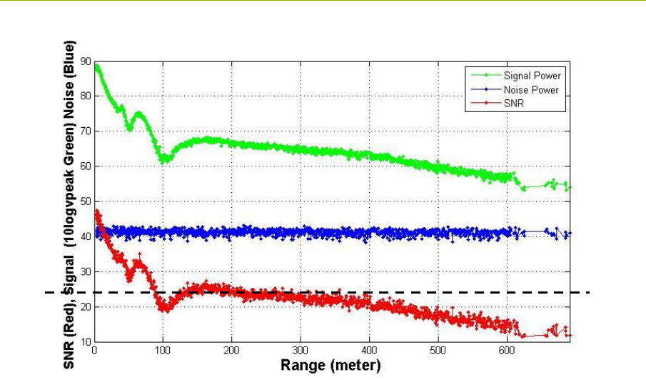
P440 Data Sheet / User Guide DRAFT 51
Fig. 34: Fresnel cancellation at 100 m can limit performance. If the SNR required to operate
was 23 dB as shown by the black line, then the radio will work out to 210 m but not between 90
and 120 m.
When operating long distance one must take Fresnel into consideration. If the operating environment
is such that Fresnel is neither a help nor a hindrance, then the operating range will be set using free
space propagation. If Fresnel is both a help and a hindrance, then the maximum operating distance
should be determined by the Fresnel enhancement, assuming that the Fresnel cancellation is not so
deep as to cause a problem.
The magnitude of the ambient RF noise can also be a limiting factor. In Figure 34, the blue line is a
measurement of the magnitude of the noise as a function of receiver location. If the ambient RF noise
were 9 dB higher than shown, then the received SNR would be 9 dB lower. In this case, the
maximum range of the link operated in Figure 34 would be 200 meters and there would be a
coverage gap between 90 and 120 meters. Ambient noise can be increased by an exceptionally strong
out-of-band transmitter or other transmitters operating in the P440’s operating band.
Assuming that ambient noise is not a factor, and there are no other factors in play, then a standard
P440 with a standard Broadspec antenna should operate as shown in Table 4. Two performance
columns are shown, one for Free Space and the second for Open Field. The difference between the
two reflects that fact that the Open Field performance benefits from Fresnel constructive interference
caused by the ground reflection. The Free Space performance would be expected if the ground
reflection were not a factor. Examples include operation between two drones well above the ground
and operation at short range (<70 m) where the Fresnel benefit is not significant.
This data for the Free Space calculation was taken with the units placed at 1 meter separation, in a
low noise environment, with fixed attenuators inserted to provide loss associated with distance. Max
Range in this case means the maximum range at which >98% of the range requests completed
successfully. At longer ranges, the range request success rate will drop. If a 50% success rate can be
tolerated, then the maximum ranges can be extended by about 20%. The Open Field data was taken
experimentally with actual P440s operating in an actual open field.

52 DRAFT P440 Data Sheet / User Guide
Table 4: Maximum operating range of a P440 range measurement system in Free Space and
over an Open Field for various Pulse Integration Index (PII) settings
6.3 Range Measurement Rate
Ranging Conversation Time is the amount of time required to take a single TW-TOF range
measurement. The maximum measurement rate is limited by the Host to P440 overhead required to
initiate a range request. This overhead will limit the measurement by approximately 30% of the
values shown in the table below. This overhead is eliminated when the range requests are handled
through RangeNet.
The Maximum Range Measurement Rate is shown in Table 5 and is achieved when two radios are
operated as a network consisting of a single requester unit and a single responder unit.
Table 5: Data and ranging performance characteristics at maximum legal transmit power
6.4 Precision Range Measurement Precision, Accuracy, and Bias
6.4.1 Precision and Accuracy in LOS Conditions
The Line of Sight (LOS) Precision and Accuracy specification is based on a measurement campaign
that included 20,000 range measurements taken in an open field, over an operating range that varied
from 2 ft. to 300 ft., for PIIs 4 through 8 inclusive, at minimum and maximum transmit gain, when
the received signal was linear and also when it was in compression. The quoted values are the results
of the composite of all of the measurements. This includes combinations of settings that may not be
PII
Max Range (m)
(Free Space)
Typical Max Range (m)
(Open Field)
466
5101
6145
7207 500
8260 600
9410 800
PII
Range Conversation Time
(milliseconds)
Maximum Range
Measurement Rate (Hz)
48.0 125.0
59.7 103.1
613.7 73.0
721.3 46.9
836.7 27.2
968.0 14.7

P440 Data Sheet / User Guide DRAFT 53
reasonable (e.g., operation at minimum range and maximum transmit power). It is believed to be a
conservative estimate of the system’s ranging Precision and Accuracy.
The precision of measurements can be improved with averaging. Measuring 6 readings will
normally improve the accuracy by a factor of 2. Averaging more than 6 readings will have only
marginal improvements.
The measurement campaign referenced above was conducted in 2011. Since that time several
significant improvements have been made to the range measurement algorithm. The overall
measurement accuracy (precision and bias) has been field-verified using a survey-grade laser. While
the test was limited in scope, the results suggest that the overall measurement accuracy is
substantially better than the value quoted in this specification. These tests were conducted in an open
field and indicate overall accuracy closer to 1 cm. While the tests’ size is too limited to warrant a
change in the published specification, the user should expect similar results, especially when
operating in a similar environment.
By constraining operation to a narrower field of application, users have achieved higher performance.
One user has reported accuracies of 0.5 cm while a second reports 2 mm accuracy.
6.4.2 Precision and Accuracy in NLOS Conditions
Time Domain does not have a specification for accuracy in Non-Line of Sight (NLOS) environments.
This is because of the wide variety of conditions that can be encountered. For example, if one is
measuring range inside a building that is constructed of wood frame and drywall (also known as
sheetrock or gypsum board), then one will experience a level of performance that is less than but
close to LOS conditions. This is because wood and drywall do not significantly attenuate or disperse
RF signals at the P440’s operating frequency. At the opposite end of the propagation spectrum would
be operation inside a metal ship. Because metal blocks radio frequencies, the operating range would
be limited to the size of the room. Operation in NLOS conditions must be determined empirically.
Having said that, we routinely measure range from one side of our office space to the other (a
distance of 30 meters through an environment that is not only NLOS but is also occluded by large
amounts of metal) with an accuracy of better than +/- 1 meter.
6.4.3 Bias and Calibration
The Precision (Standard Deviation) and Accuracy (Bias error) of the TW-TOF range measurement
are called out in Section 6.1, Table 3 and discussed in Section 6.4.1.
It should be noted that Bias is measured using the standard Broadspec antenna with a 90-degree SMA
connector.
When a P440 leaves the factory its bias will be zeroed to within a few centimeters. This ensures that
when a user takes a range measurement, the result should compare favorably with a measurement
taken with a laser. This assumes that the measurement is clear line of sight, not in compression and
not affected by Fresnel cancellation or enhancement. If that is the case, then most users will find the
result satisfactory. Furthermore, this result will not change materially over the operating temperature
range.
However, sometimes it is necessary to use a different cable, connector or antenna. In this case the
Bias will change. Furthermore, some applications may require a more accurate zeroing of the Bias
than what is normally provided from the factory. In either of these cases it will be necessary to
characterized and adjust individual P440s. Application note 320-0327 Distributed Calibration of
Time Domain UWB Radios describes such a process. Once the user has determined by how many cm
the calibration needs to be adjusted, then this number should be converted to picoseconds and entered
through the RCM_Set_Config_Request API message or through the Configuration Tab on the

54 DRAFT P440 Data Sheet / User Guide
RangeNet RET GUI. To convert from cm to picoseconds, use the following equation:
0.2993 mm of delay = 1 picoseconds
In other words, if you add a cable between an antenna and an antenna port which has exactly 1 meter
of delay, then you should increase the value of the antenna delay for that antenna port by 3341ps.
6.5 CRE Range Measurement Precision and Accuracy
There are three key factors that affect the Precision and Accuracy of a CRE measurement: stability of
the RF channel, changes in antenna pattern and signal strength.
If RF channel characteristics are stable, then the accuracy of the CRE measurement should be close to
that of the reference precision range measurement (PRM). However, if the P440 is physically
moving, such that the associated antenna pattern changes, then the RF channel will change with time.
Therefore, the recalibrating PRMs should be taken frequently enough such that the rate of change
(“drift”) of the RF channel will be small. This rate of change will vary with node speed and change
in orientation and must be determined empirically.
Random effects, including sampling variability, can cause a static node’s signal strength measurement
to vary by as much as 10%. The CRE error is also a function of distance between the transmitter and
receiver largely because as a weaker signal contains a higher proportion of noise elements. This
translates into a CRE standard deviation error of approximately 10% at short distances, growing up to
30% at very long distances. CRE should not be used at distances greater than 100 meters. At these
distances, the change in signal strength with distance is very small and can be less than the average
reading-to-reading variation at any given point. In addition, one will normally encounter Fresnel
enhancement beyond about 100 meters. In these cases the SNR will actually increase with distance.
This is illustrated in Figure 34.
6.6 Data Communications Rate and Throughput
The P440 has been optimized for operation either as a Radar or as a Ranging Radio. While the P440
can be used to transmit large quantities of data, this capability will come at the expense of ranging
update rate. It is also important to note that data transmissions are limited to a maximum of 1000
bytes per packet. While fewer bytes can be transmitted, the highest throughput is achieved when the
bytes sent per packet are maximized. Table 6 shows the relationship between PII (Pulse Integration
Index) and data throughput.
Table 6: Throughput for different Pulse Integrations and buffer sizes
It should also be noted that the bit rate will vary by a few percent depending on which Code Channel
is selected.
Bytes sent using Code Channel 2
100 1000
PII Bit rate (kbps) Bit rate (kbps)
4270.46 612.48
5192.77 308.48
6138.56 144.64
762.14 76.80
834.88 39.04
917.41 19.20
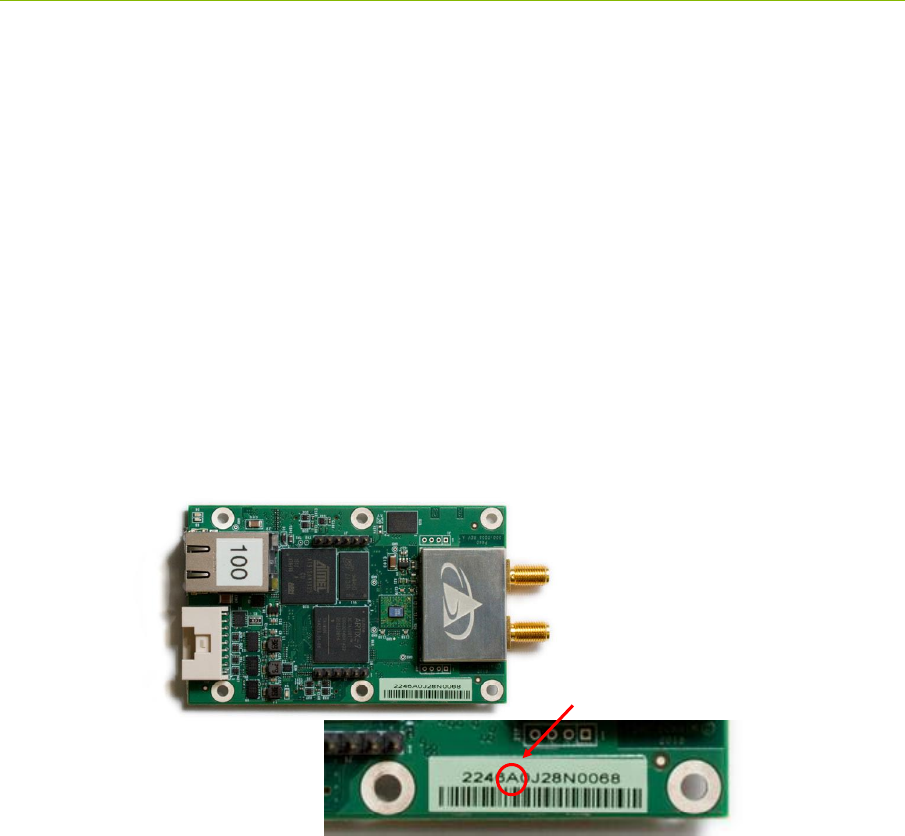
P440 Data Sheet / User Guide DRAFT 55
6.7 Operating Range of P440 Radar
The detection range of a UWB Radar is a strong function of the antennas used, the ambient
environment, clutter, target size and movement characteristics, as well as the robustness of the user
developed signal processing. The quoted detection ranges have been achieved by others and
represent close to the maximum detection range achieved to date without using heroic measures.
Users limited to the legal maximum transmit power and with no antenna flexibility should half the
numbers shown in Table 3.
For additional insight into this subject, a validated Radar Range Equation for the P440 is provided on
the Time Domain website.
6.8 P440 Version Differences
From time to time slight changes or improvements are made to the P440 design. The version or
revision level of any given P440 is indicated in the bar code of that particular P440 (See Figure 35
below).
Fig. 35: P440 Version indicated in bar code. Unit shown is a Rev A board.
The following is a list, by revision level, of any deviations or changes/improvements from this data
sheet.
P440 Rev A
Ethernet through the mezzanine connector is not supported.
Operation of the unit at the temperature limits is not recommended. Failures have been
reported. Avoid using the equipment in extreme outdoor temperatures.
Avoid operating units in high vibration.
If failures do occur in either high vibration or extreme temperature contact Time Domain
customer service.
P440 Rev B
Ethernet through the mezzanine connector is not supported.
Rev A board
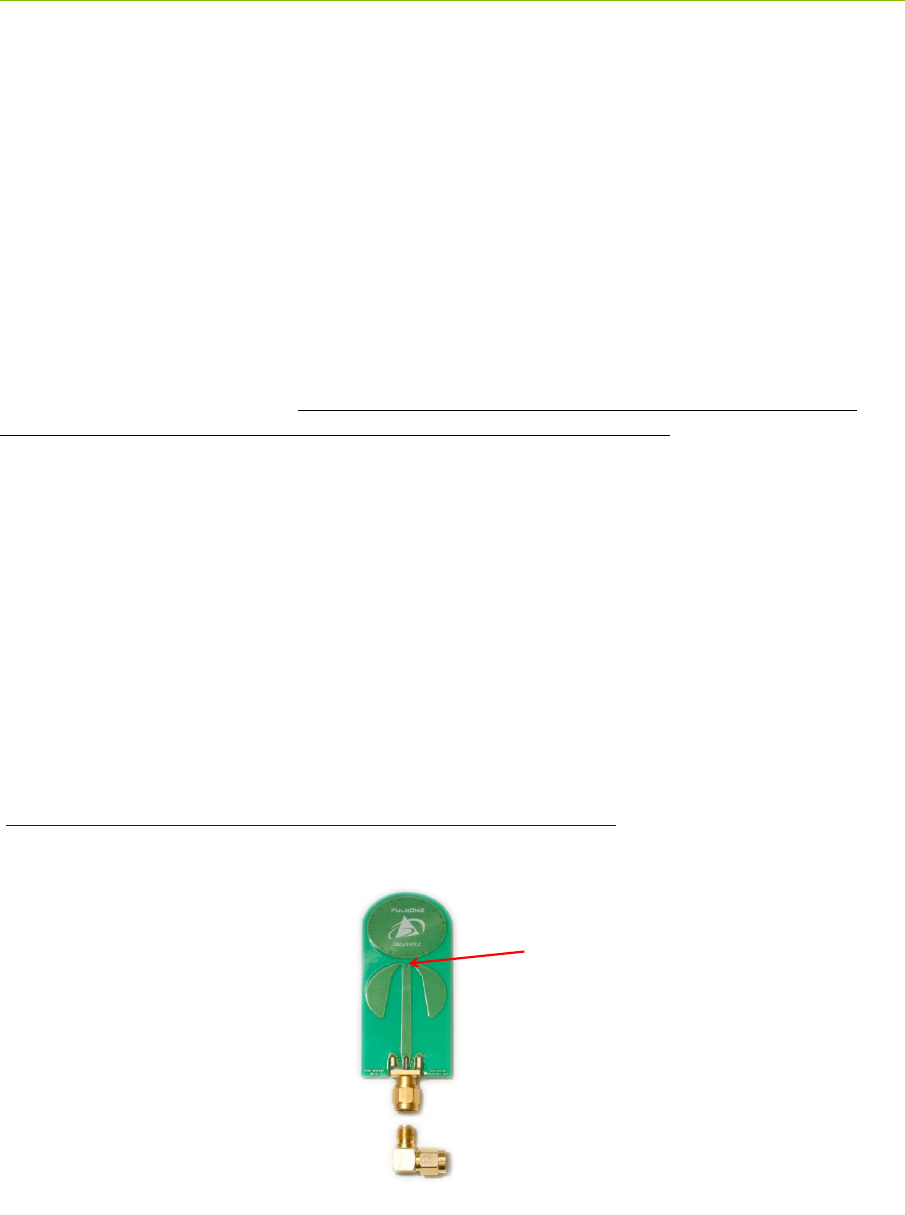
56 DRAFT P440 Data Sheet / User Guide
7 Broadspec Antenna
The P440 is designed to operate with the Broadspec antennas shown in Figure 36. While this is the
antenna provided with the P440, the unit can accommodate a wide variety of standard and custom
antennas. The only electrical requirement is that the antenna used has a 50 ohm SMA connection.
Using a different antenna will likely change the beam pattern and gain, either of which will affect
certification. Using a different antenna may change the phase linearity and compromise the pulse
shape and integrity. This can affect the performance of the range measurement algorithms.
However, all of the transmit settings have been set assuming that the P440 is connected to the
Broadspec. In fact, the pending US certification effort will require use with the Broadspec antenna.
Using any other antenna (or even adding cabling between the P440 and the antenna) will require
recertification of the equipment.
For example, as per FCC 15.203, the Broadspec antenna must be professionally installed and the
installer has the responsibility to insure that the Broadspec antenna is used.
EU regulations have similar restrictions.
The P440 can be operated with a single antenna (used for transmit and receive) or with two antennas
(where one is dedicated for transmit and the second for receive).
The Broadspec antenna (~3 dBi) provides an omni-directional transmit/receive pattern supporting a
frequency range of 3.1-5.3 GHz. It has a standard SMA male connector and measures 1.2” x 2.5” x
0.063” (3.0 x 63.5 x 1.6 mm). When ordered with a Kit it is also provided with a 90-degree connector
as shown in Figure 36.
The connector can also be ordered with a standard SMA female connector. See Section 10 for
ordering details.
Specifications are available on the web at:
http://www.timedomain.com/datasheets/TD_Broadspec_Antenna.pdf
Fig. 36: Broadspec antenna with phase center indicated
Phase Center

P440 Data Sheet / User Guide DRAFT 57
8 Regulatory Compliance
The P440 has been designed to be in compliance with both the U.S. FCC Part 15 subpart F
regulations, sections 15.519 and 15.521 and with the European Union ETSI EN 302 065 standards.
Two different versions of the P440 are available, one version supports the FCC emissions mask
(Region 1) and the second supports the ETSI standard mask (Region 2). This is discussed in greater
detail in the following subsections and in Section 10 – Configuration and Ordering Information.
Any version provided with the optional power amplifier is not certified.
The P440 with Broadspec antenna is currently in the process of being certified in the US as a
standalone device. This certification is expected late in 2015.
Integration of the P440 into other user equipment will require certification of the resultant system.
While that certification is the responsibility of the end user, Time Domain will be happy to assist in
this process.
The design difference between a Region 1 and Region 2 device is very slight. The key difference is
then severity of the filter band edges. Since the Region 2 device (EU) has the more severe
requirement, that design is inherently also in compliance with the Region 1 regulations.
8.1 Compliance with the U.S. FCC Regulations
The standard Region 1 P440 has been designed to be in compliance with the FCC regulations
governing UWB hand-held systems (Part 15.519) also known as “battery powered devices” or
“mobile devices.” This means that the device can be incorporated in a wide variety of products
including mobile tracking systems, mobile locators, radar-based locators, guidance and position
systems, and communication devices. Note that there are other applications which are specifically
forbidden, such as use of the devices in toys. See FCC Parts 15.519 and 15.521 for more details.
More specifically:
This device complies with 47 CFR Part 15 of the FCC Rules. Operation is subject to the
following two conditions: (1) This device may not cause harmful interference, and (2) this
device must accept any interference received, including interference that may cause
undesired operation.
Furthermore:
The user is cautioned that changes or modifications not expressly approved by the party
responsible for compliance could void the user’s authority to operate the equipment.
The label which provides the certification number is shown below in Figure 37. (Note: This
certification is currently in process with formal certification expected in late 2015.)
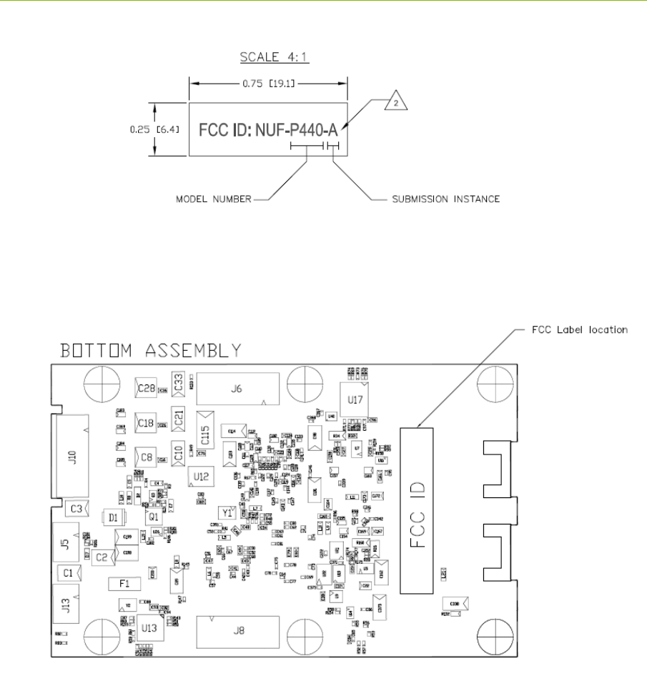
58 DRAFT P440 Data Sheet / User Guide
Figure 37: FCC ID number
This label is located on the back or bottom side of the P440. See Figure 38.
Fig. 38: Location of certification number
If the P440 is incorporated into a different enclosure it is possible that the enclosure can alter the
unintentional and intentional emissions respectively.
Based on requirements from a number of government and site-license customers, the P440 is capable
of transmitting at power levels in excess of the FCC limits for enhanced performance. In order to use
these higher powers, please consult and seek authorization from the appropriate regulatory agencies.
Time Domain has expertise in working with regulatory agencies and can help as needed. However,
the responsibility for obtaining such authorization rests with the end user.
Additionally, the FCC regulations do not apply for US government or military applications. Proper
governmental use is described in “Government Regulations for Non-Licensed UWB Systems - Annex

P440 Data Sheet / User Guide DRAFT 59
K.” Developers interested in building a device for a particular government agency should discuss
their application and Annex K with that agency’s spectrum manager.
Time Domain is available to assist you with the certification process.
8.2 Compliance with the EU ETSI Standards
The standard Region 2 P440 has been designed to be in compliance with the emissions mask defined
in the ETSI EN 302 065 standard.
The user is free to buy the equipment for evaluation and demonstration purposes. But before the
device can be generally marketed as an end product, its operation must be compliant with the ETSI
standard. The ETSI standard places additional requirements on operation of UWB devices beyond
just the emission mask. These requirements are related to the specific end application. For example,
depending on the user’s intended application, there can be additional limitations (or flexibilities) on
the location of fixed and mobile transmitters as well as on the rate at which transmissions can be
generated. There are also alternate mitigation strategies which can be used to accomplish the intent of
the standard. These strategies need to be considered in the context of the target application.
The ETSI regulations also evolve over time with changes being introduced periodically. Product
developers need to keep this in mind as they evaluate applications and target products.
Finally, the P440 by itself cannot be certified. The P440 must be certified by the relevant body in the
context of the final product in which it is to be used.
Time Domain is available to assist you with the certification process.

60 DRAFT P440 Data Sheet / User Guide
9 Import/Export Considerations
Time Domain has self-certified the P440 in all its variations under Export Commodity Control
Number (ECCN) 5A001b.4 pending formal classification from the U.S. Department of Commerce’s
Bureau of Industry and Security. This self-certification is based upon the Bureau’s previous
assignment of ECCN 5A001b.4 to the company’s P400 modules. Products falling under ECCN
5A001b.4 are controlled for export purposes pursuant to the Commerce Control List for National
Security and Antiterrorism. For the latest information from the Commerce Department on Export,
please go to: http://www.bis.doc.gov/licensing/exportingbasics.htm.
While Time Domain has shipped product to more than a dozen countries (and takes pride in doing so)
there are a small number of countries for which export license approval may be required.
Furthermore, these rules change with time. Therefore, the company reluctantly reserves the right to
refrain from selling P440s if there is a significant export concern.

P440 Data Sheet / User Guide DRAFT 61
10 Configuration and Ordering Information
The P440 is available either as a single board (Industrial Module) or as part of a Development Kit or
Lab package (Kit module). When ordered as part of a Kit, the P440 module is provided with a
number of hardware and software accessories. Also Kit modules are powered through the USB
connector while Industrial Modules are typically powered through the Locking connector. For
details on how the IP address and Node Id are defined for Kit and Industrial Modules see Section
4.4.5 – Ethernet and IP Addressing.
The hardware accessories include the following:
Enclosure for P440 module: Housing made of damage-resistant plastic with clear
polycarbonate cover. Provides protection from improper handling during evaluation, testing,
and development activities.
Broadspec antenna: Time Domain’s standard UWB antenna as described in Section 7.
USB wall charger, battery, and cables: The USB battery can drive the P440 directly for
approximately 5.5 hours. The USB wall charger can drive the P440 directly from an AC
power source or can be used to recharge the battery. A short USB cable is provided for
connecting the battery to the P440 and a longer cable is provided for driving the P440 from
an AC plug or for USB communications. Most (but not all) commercially available USB
battery packs will drive the unit, so the user has the freedom to experiment with alternate
battery approaches.
The P440 software offerings include the following:
RangeNet / RangeNet Lite: RangeNet is Time Domain’s GUI for demonstrating two
different capabilities. First, it allows the user to measure the distance between two P440 units
using TW-TOF ranging. Second, it allows the user to define a network of P440s. More
importantly, this network has been optimized for use with TW-TOF ranging. RangeNet
supports both the ALOHA and TDMA network protocols. It can also be configured to
transfer low rate data. RangeNet “Lite” is a node-locked version of RangeNet in that it is
limited to operation with 10 nodes. RangeNet Lite is provided to allow the user to easily
experiment with units both as standalone pairs and as members of a network. Users
interested in unrestricted operation of RangeNet should contact the factory for information on
purchase and licensing options.
MRM RET: This is Time Domain’s GUI for demonstrating the operation of the P440 as a
monostatic radar. MRM RET can be used as a training tool to familiarize the user with the
API commands or as an actual development tool.
CAT: The Channel Analysis Tool (CAT) allows the user to operate the P440 either as a
bistatic or multistatic radar. It is also well-suited for performing studies to determine the RF
channel propagation studies.
All of the software packages come with sample C code and sample MATLAB code to illustrate the
API interface from a Host computer to the P440.

62 DRAFT P440 Data Sheet / User Guide
The following table provides the name of the configuration, a part number, and short description of
the part or kit. Two hardware versions are available and are designated as Region 1 or Region 2.
Region 1 hardware is intended for those countries that follow the U.S. FCC emissions regulations and
Region 2 hardware is intended for those countries that follow the EU ETSI standards.
KIT Series
Part number
Description
P440 Ranging and
Localization
Development Kit
440RL01 (Region 1)
440RL02 (Region 2)
Contains
5 P440 modules
o 140RM01 for Region 1
o 140RM02 for Region 2
5 Broadspec antennas (100ANR3)
5 enclosures
5 rechargeable USB batteries
5 USB wall chargers
5 long USB cables (6 ft./1.8 m)
5 short USB cables (6 in./15cm)
RangeNet Lite (ranging and
network software, node-locked to
10 nodes)
5 hours of technical support
MATLAB-based localization
demonstration
P440 Radar
Development Kit
440MR01 (Region 1)
440MR02 (Region 2)
Contains
2 P440 modules
o 140RM01 for Region 1
o 140RM02 for Region 2
4 Broadspec antennas (100ANR3)
2 enclosures
2 rechargeable USB batteries
2 USB wall chargers
2 long USB cables (6 ft./1.8 m)
2 short USB cables (6 in./15cm)
MRM and CAT (monostatic and
multistatic radar as well as the
Channel Analysis Tool for
communication RF channel
analysis and modeling)
5 hours of technical support
LAB Series
P440 PulsON Lab
540PL01 (Region 1)
540PL02 (Region 2)
Contains
10 P440 modules
o 140RM01 for Region 1
o 140RM02 for Region 2
20 Broadspec antennas (100ANR3)
10 enclosures
10 rechargeable USB batteries
10 USB wall chargers
10 long USB cables (6 ft./1.8 m)
10 short USB cables (6 in./15cm)

P440 Data Sheet / User Guide DRAFT 63
RangeNet Lite (ranging and
network software, node-locked to
10 nodes)
MRM and CAT (monostatic and
multistatic radar as well as the
Channel Analysis Tool for
communication RF channel
analysis and modeling)
10 hours of technical support
P440 PulsON MegaLab
540PL04(Region 1)
540PL05 (Region 2)
Contains
20 P440 modules
o 140RM01 for Region 1
o 140RM02 for Region 2
40 Broadspec antennas (100ANR3)
20 enclosures
20 rechargeable USB batteries
20 USB wall chargers
20 long USB cables (6 ft./1.8 m)
20 short USB cables (6 in./15cm)
RangeNet Lite (ranging and
network software, node-locked to
10 nodes)
MRM and CAT (monostatic and
multistatic radar as well as the
Channel Analysis Tool for
communication RF channel analysis
and modeling)
10 hours of technical support
Single P440 boards
P440 Kit Module
140RM01 (Region 1)
140RM02 (Region 2)
Single P440 Module (board only, no
accessories)
P440 Kit Module with
high power amp
140RM03
Single P440 Module (board only, no
accessories) with onboard power amp
P440 Industrial Module
140RM04 (Region 1)
140RM05 (Region 2)
Single P440 Module (board only, no
accessories)
Antenna Series
Broadspec Antenna
100ANR1
Single Time Domain UWB Antenna (3-6
GHz) female SMA connector and right
angle SMA connector
Broadspec Antenna
100ANR2
Single Time Domain UWB Antenna (3-6
GHz) male SMA connector
Broadspec Antenna
100ANR3
Single Time Domain UWB Antenna (3-6
GHz) male SMA connector and right angle
SMA connector
Accessory Series
P440 Enclosure
340EN01
Single P440 Enclosure

64 DRAFT P440 Data Sheet / User Guide
High Power Amplifier Option: These boards can also be provided with an optional high power
amplifier. This amplifier will boost the transmit power of the P440 by 16 dB above the regulatory
limit. This capability is provided as an aid in evaluating the performance or performance potential of
UWB. Approval to operate at these higher powers is the responsibility of the end user.
While this capability can be used for evaluation or demonstration, resale of P440s with this option
will require recertification of the unit to the relevant RF emissions requirements. Even recertification
to overcome extra cable loss will require recertification. If the goal is to increase radiated power, it
should be noted that most (but not all) regulations and regulators are unsympathetic to requests to
radiate above the published limits. See Section 8 – Regulatory Compliance for additional
information.
When ordering, please specify whether or not the high power amplifier option is required.
For pricing and ordering information, please contact sales@timedomain.com.