Humatics PLUS-0309 PLUS Name Tag User Manual Manual
TDC Acquisition Holdings Inc. PLUS Name Tag Manual
UserManual.wiki
>
Humatics
>
PLUS 0309 User Manual
Manual
Navigation menu
Upload a User Manual
Namespaces
Wiki Guide
HTML
PDF
Info
Views
User Manual
Discussion / Help
Navigation


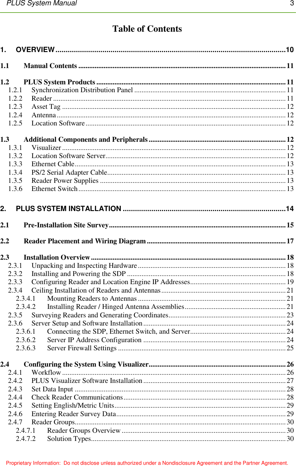
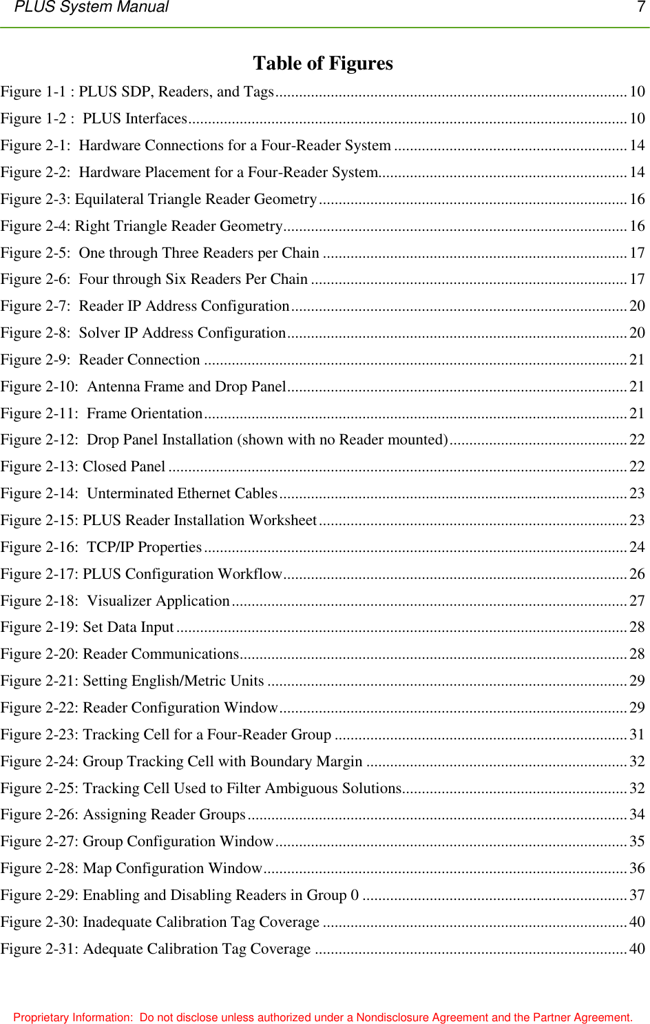


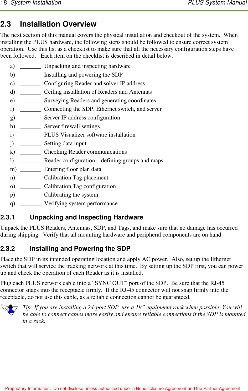

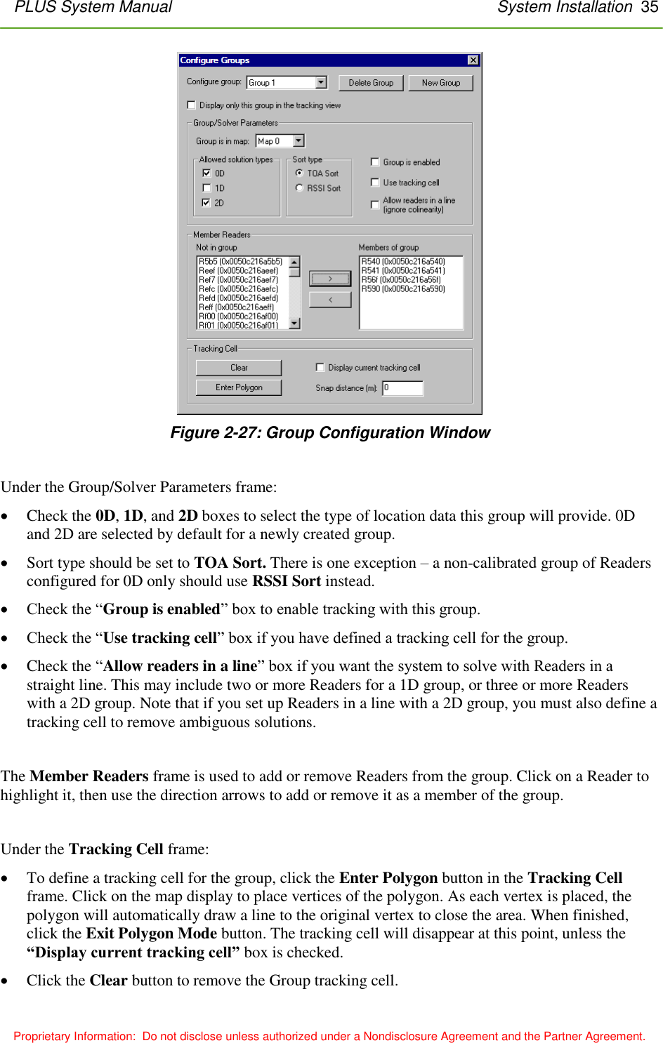
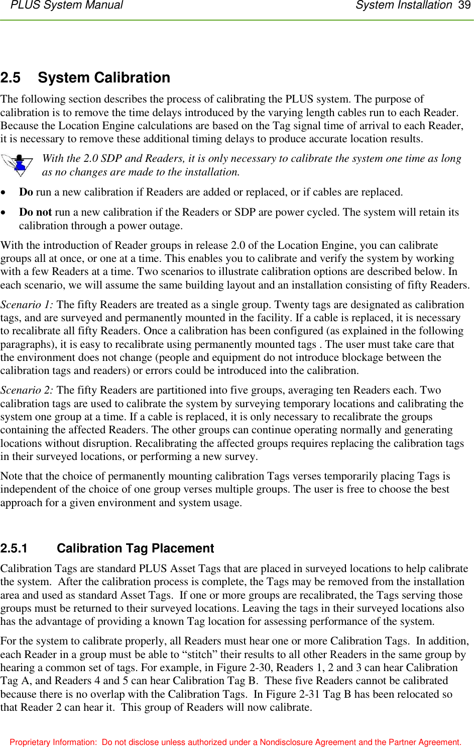
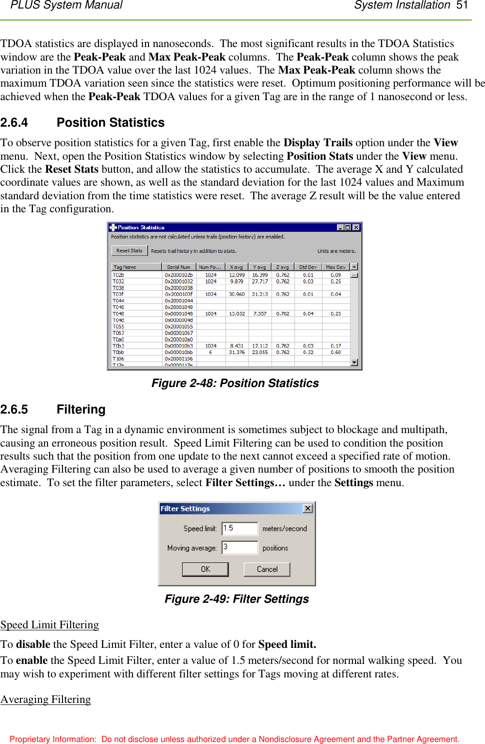
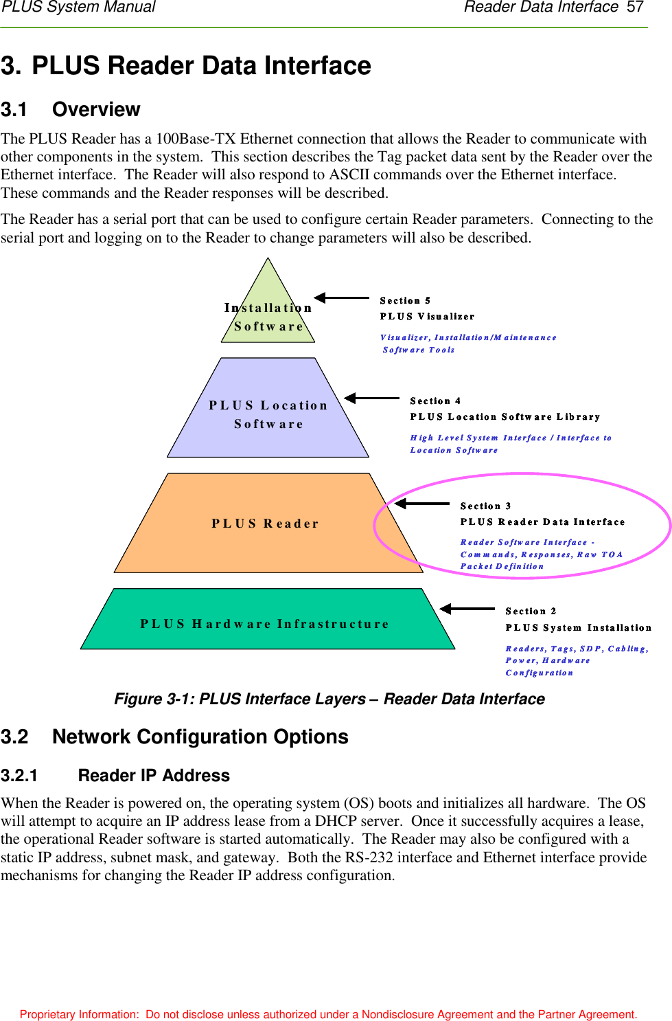
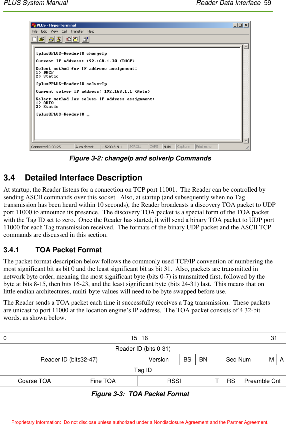
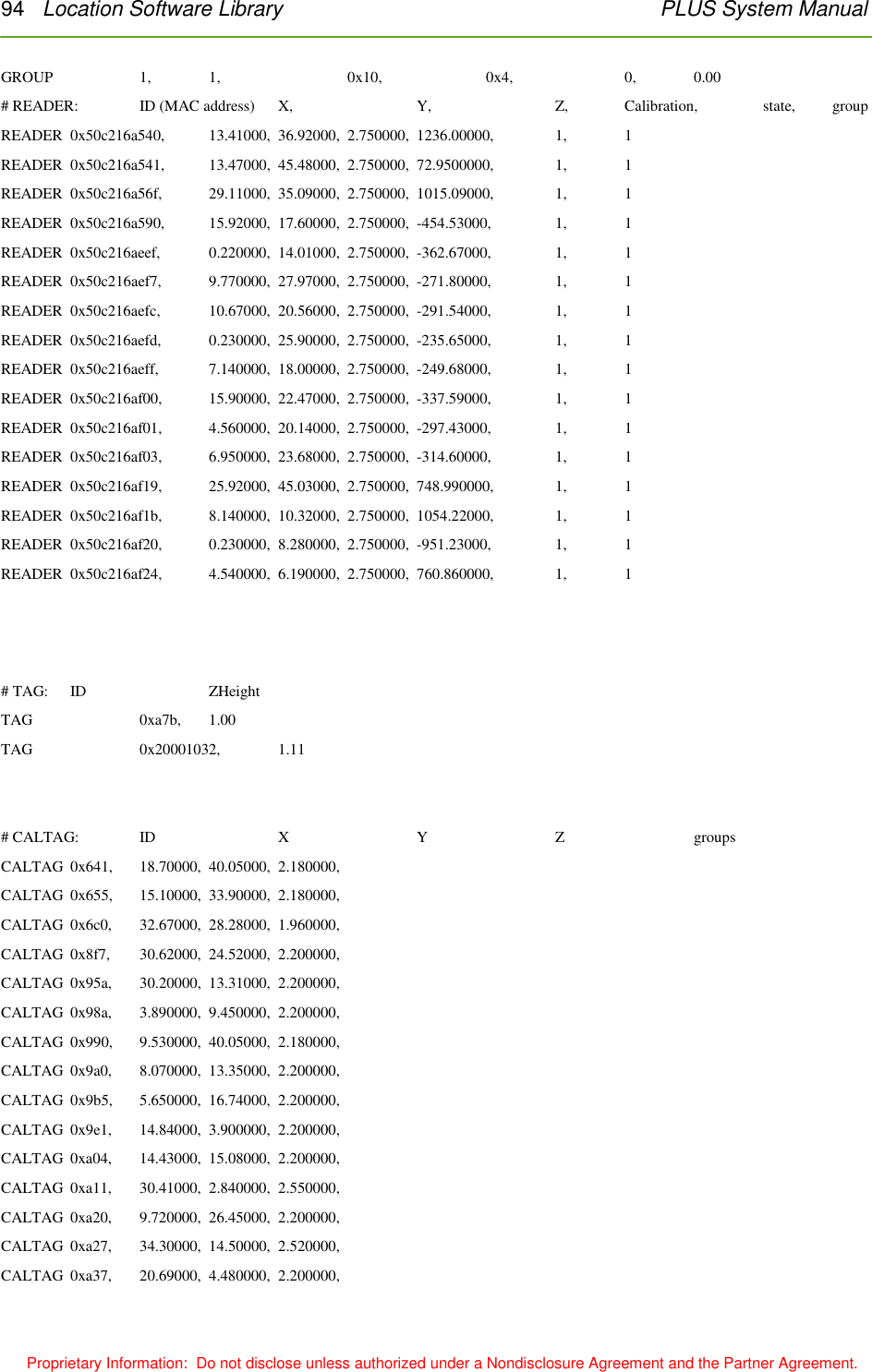
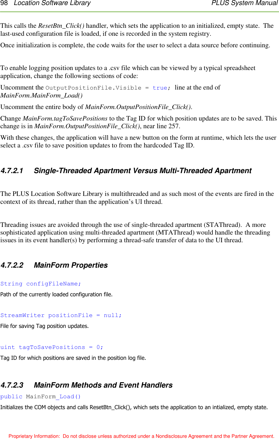
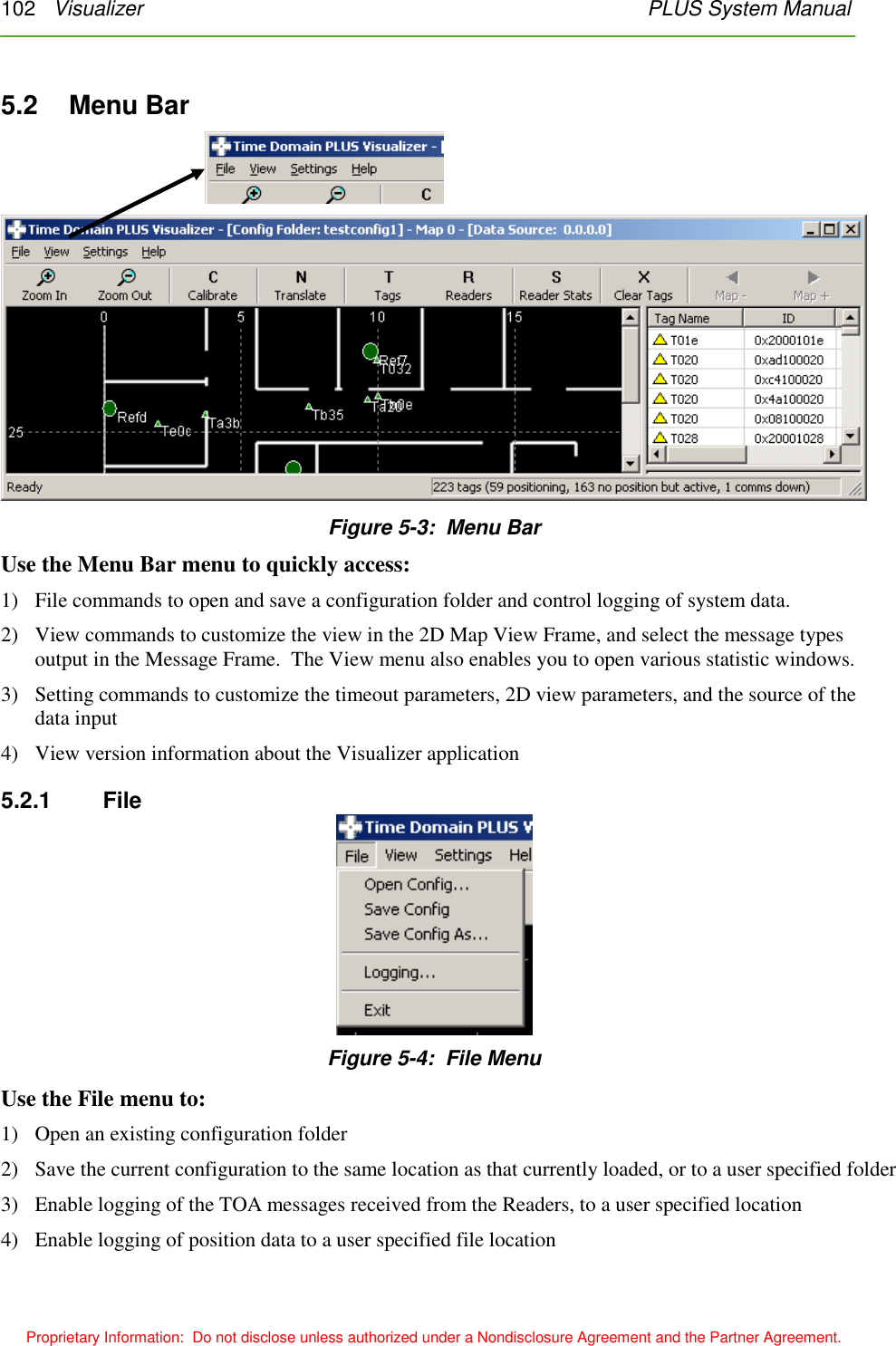
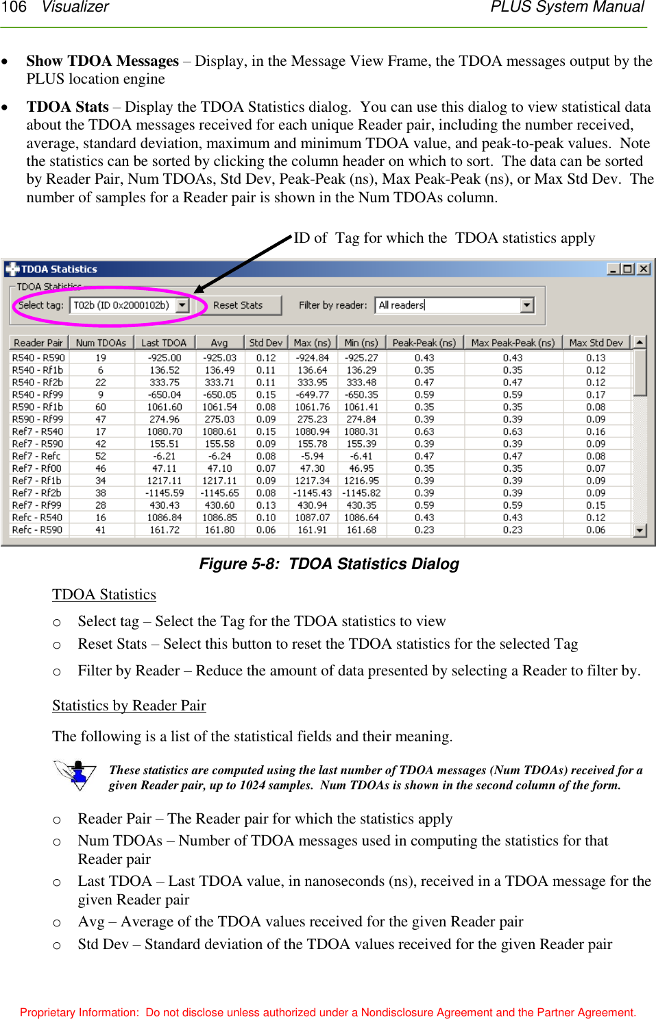
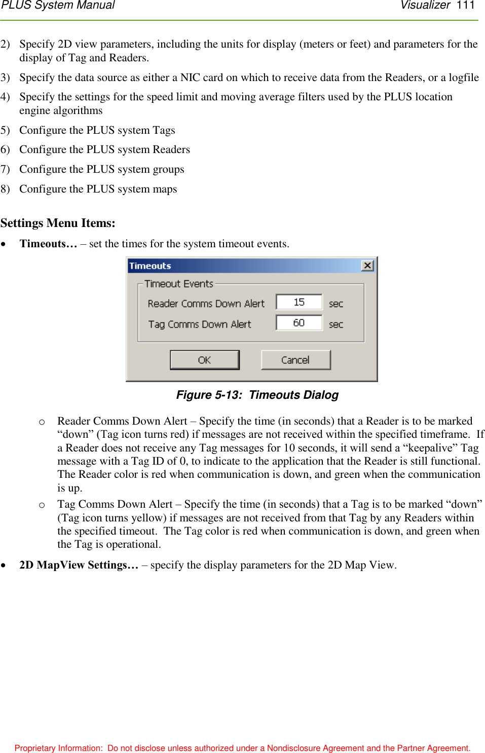
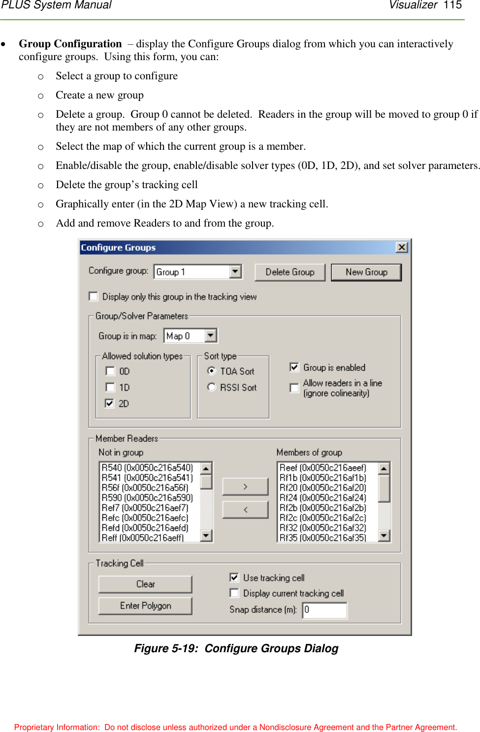
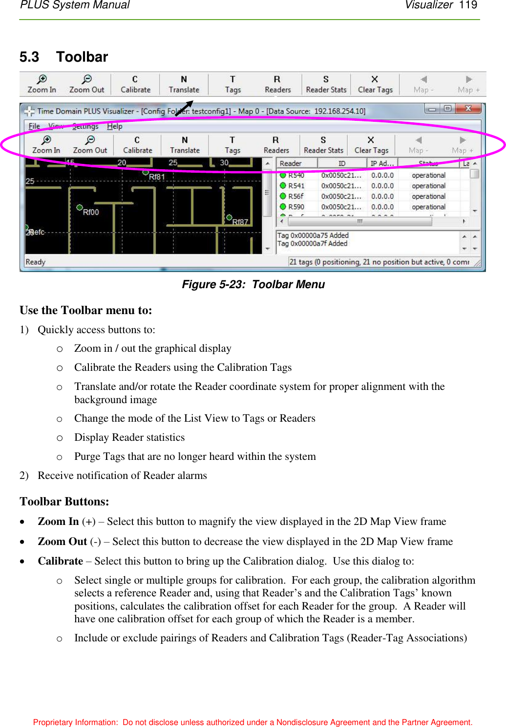
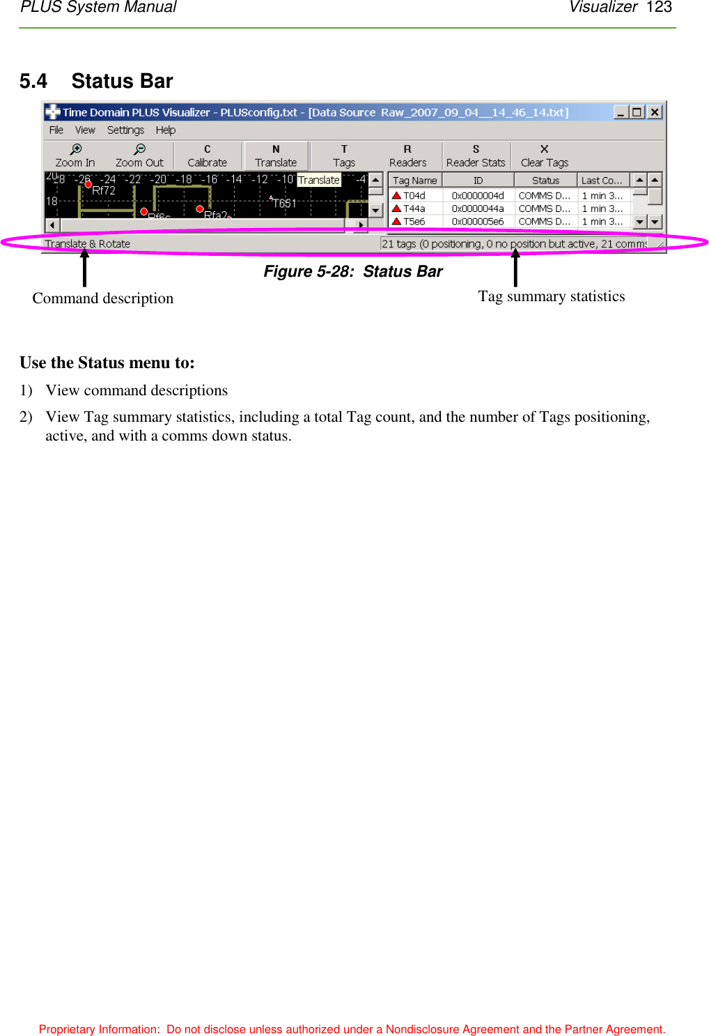
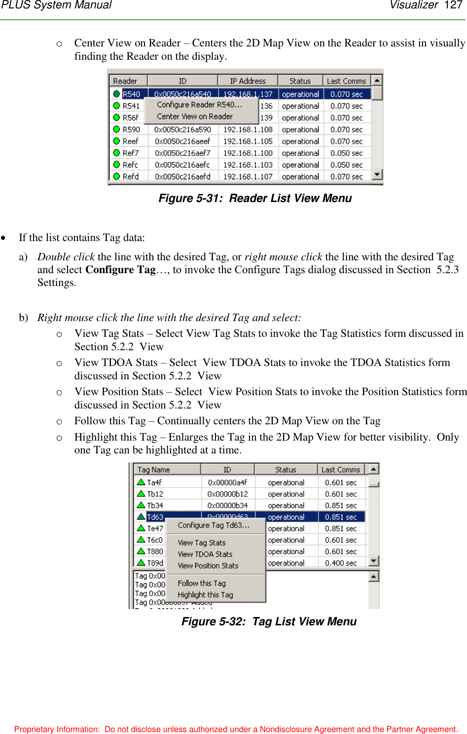
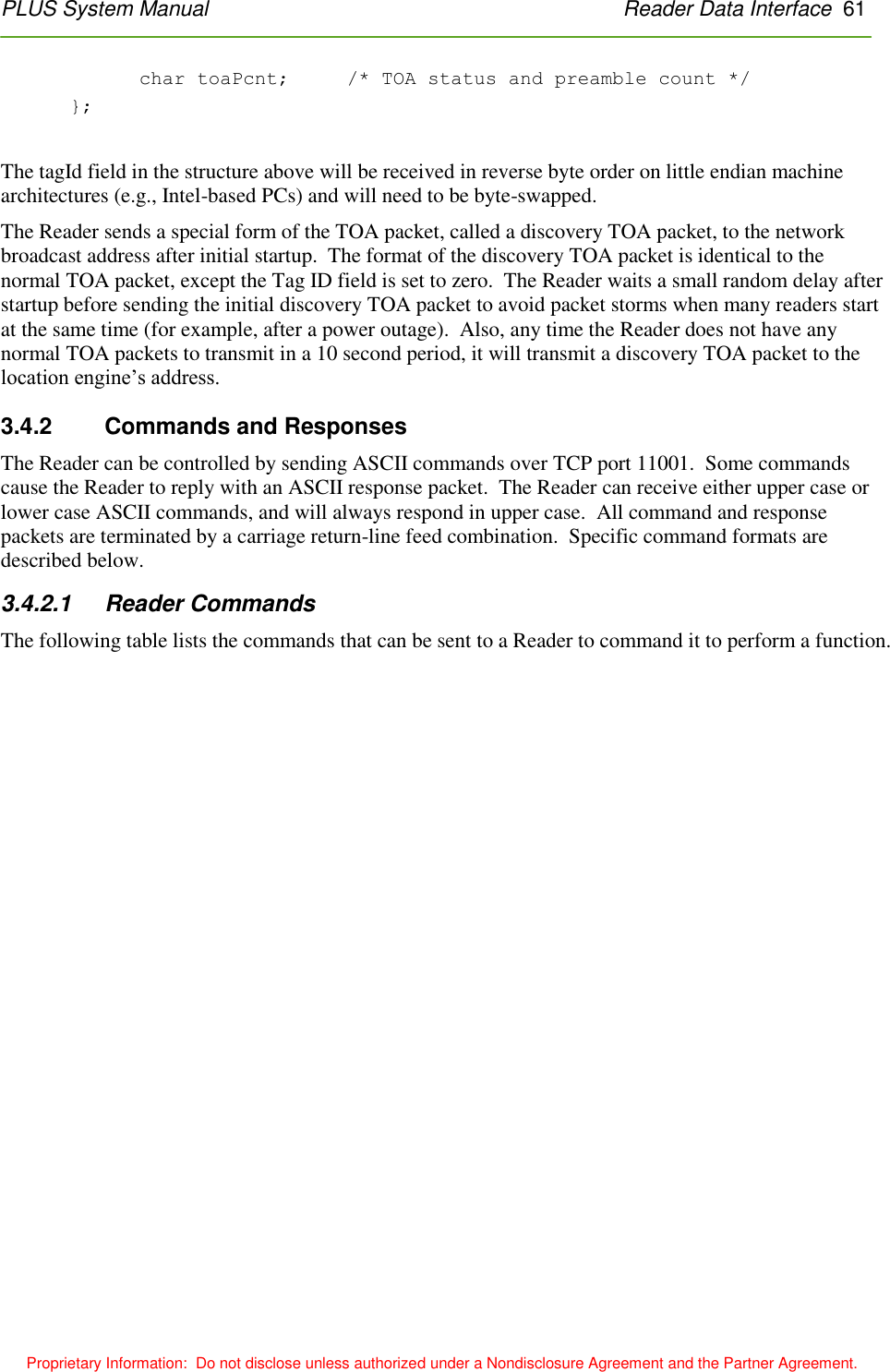
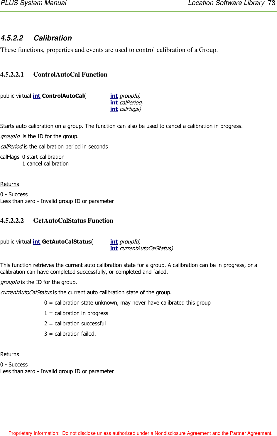
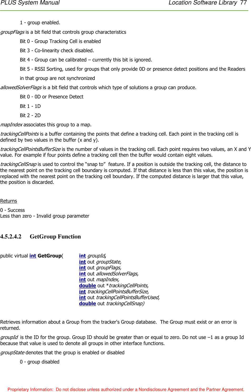
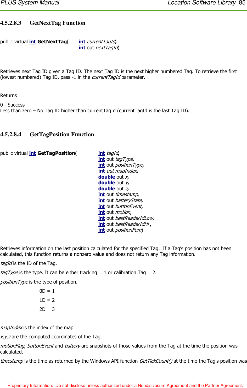
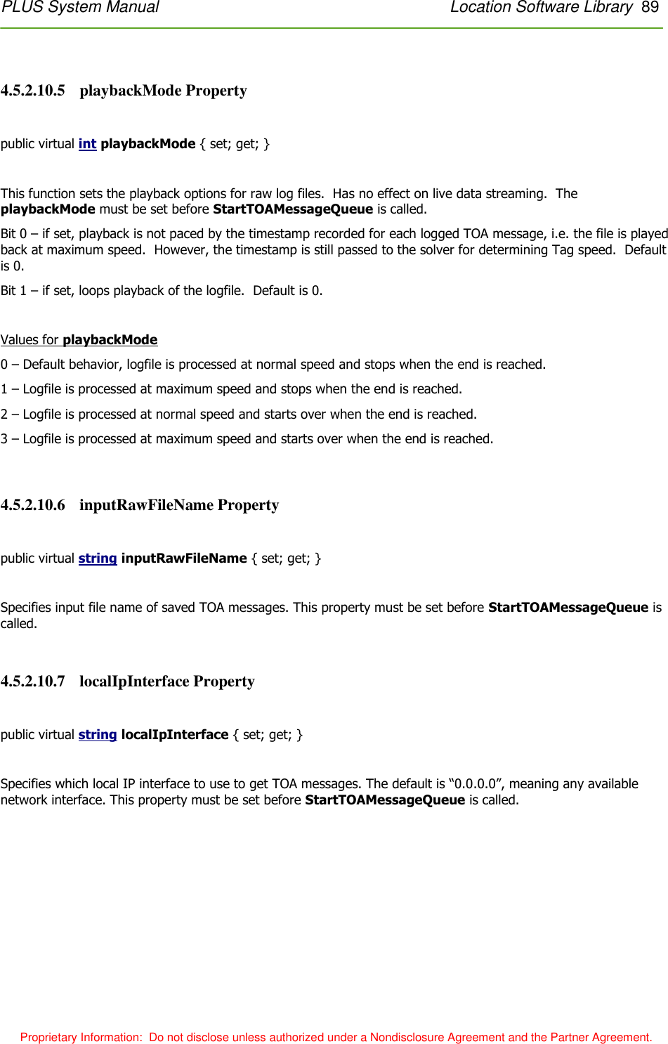
![60 Reader Data Interface PLUS System Manual Proprietary Information: Do not disclose unless authorized under a Nondisclosure Agreement and the Partner Agreement. Each field in the packet is discussed in detail below: Reader ID – The Reader’s 48-bit MAC address Version – 4-bit field that denotes the version of the data format. This document describes version 2. Each time the format of the TOA packet changes, the version number will also change. BS – 2-bit battery status reported by the Tag BN – 2-bit button event field from the Tag payload. A button event of 0 means that the button is not pressed. A value of 1 indicates a single button push event. A value of 2 indicates that the button was pressed twice. A value of 3 indicates a push-and-hold event (the button was depressed for longer than 2 seconds). Sequence number – 6-bit sequence number from the Tag payload M – 1-bit motion detect field from the Tag payload. This field is currently not implemented. A – 1-bit alarm field that indicates the Reader has encountered an error condition. Additional information can be found by querying the Reader’s alarm status and statistics. Tag ID – 32-bit ID of the transmitting Tag. This field will be zero for discovery packets. Coarse TOA – 8-bit field containing the coarse time-of-arrival value. Each bit represents 10 ns. This field is undefined if field T below is 1. Fine TOA – 8-bit field containing the fine TOA value. Each bit represents 1/256 of a 10 ns coarse interval. Thus, each bit is 39.0625 ps. This field is undefined if field T below is 1. RSSI – Received Signal Strength Indication. This 8-bit field is an estimate of the received Tag’s signal strength. The minimum RSSI value is around 20, and the strongest compressed signals peak at approximately 230. T – 1-bit field that indicates valid Coarse and Fine TOA values. A value of 0 indicates a valid TOA. A value of 1 indicates an invalid TOA and the Coarse and Fine TOA fields are undefined. RS – 2-bit field reserved for future use. Preamble Cnt – 5-bit field that indicates how many bits remained in the acquisition preamble after the acquisition threshold was passed. Higher numbers indicate stronger signals. Valid values range from 17-23. An example structure declaration in the C programming language that would hold a TOA packet is as follows: struct toa { char readerId[6]; /* reader ID */ char versionBsBn; /* version, battery status, and button event */ char seqNumMA; /* sequence number, motion detect, and alarm */ int tagId; /* tag ID */ char coarseToa; /* coarse TOA value */ char fineToa; /* fine TOA value */ char rssi; /* received signal strength indicator */](https://usermanual.wiki/Humatics/PLUS-0309/User-Guide-1077039-Page-60.png)
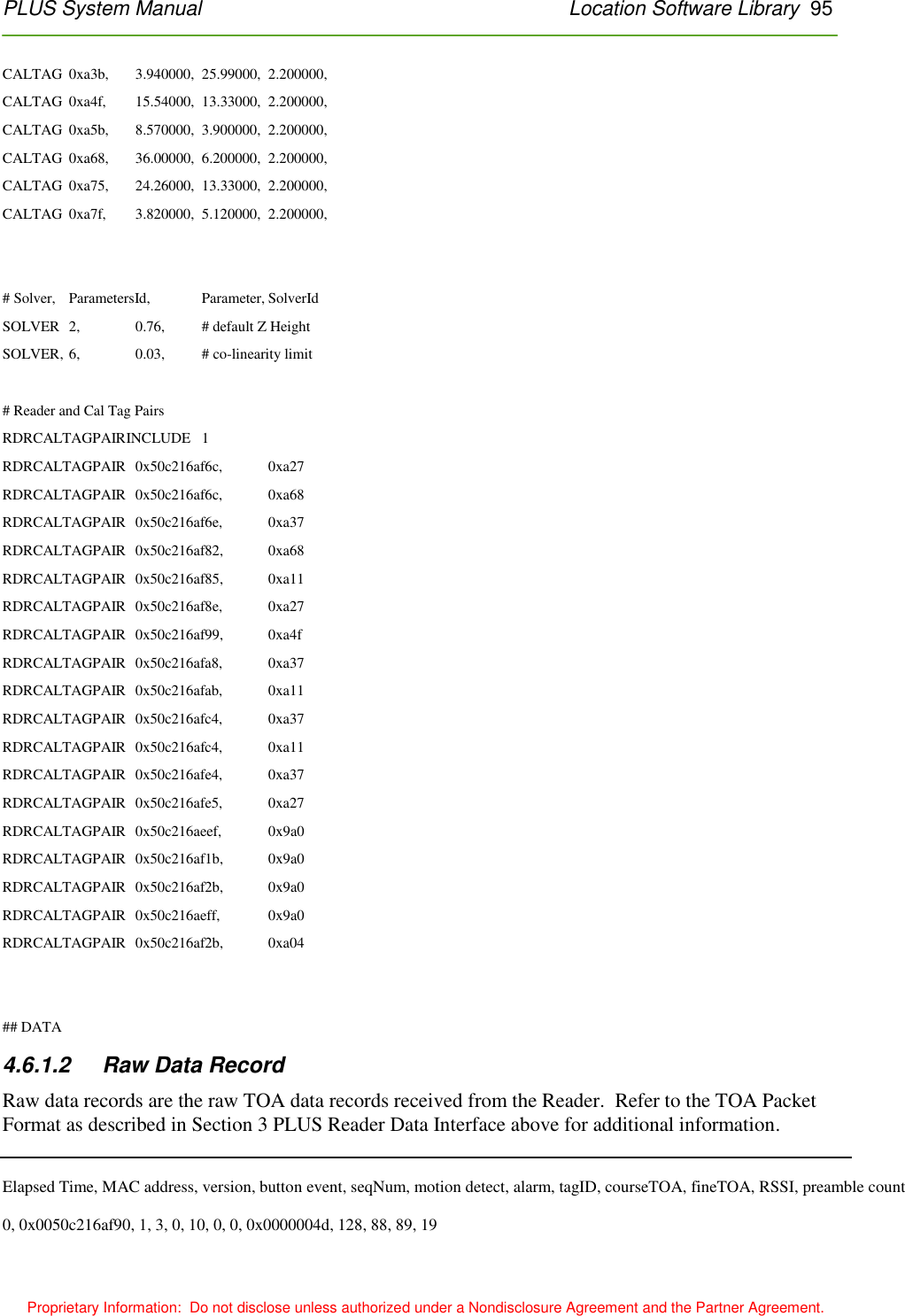
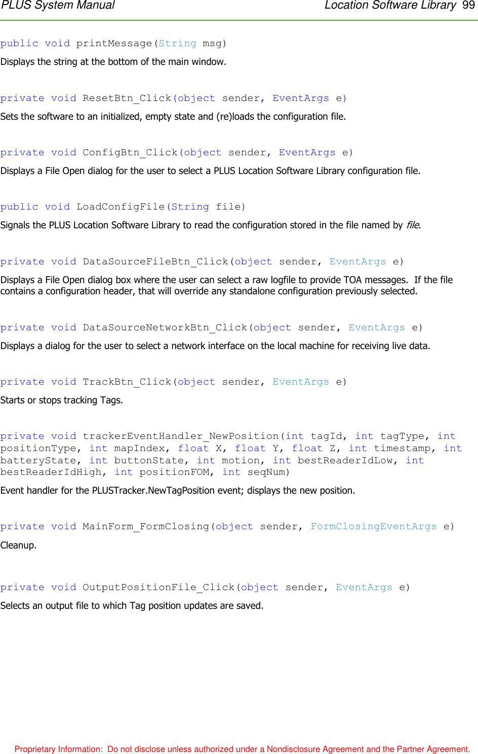
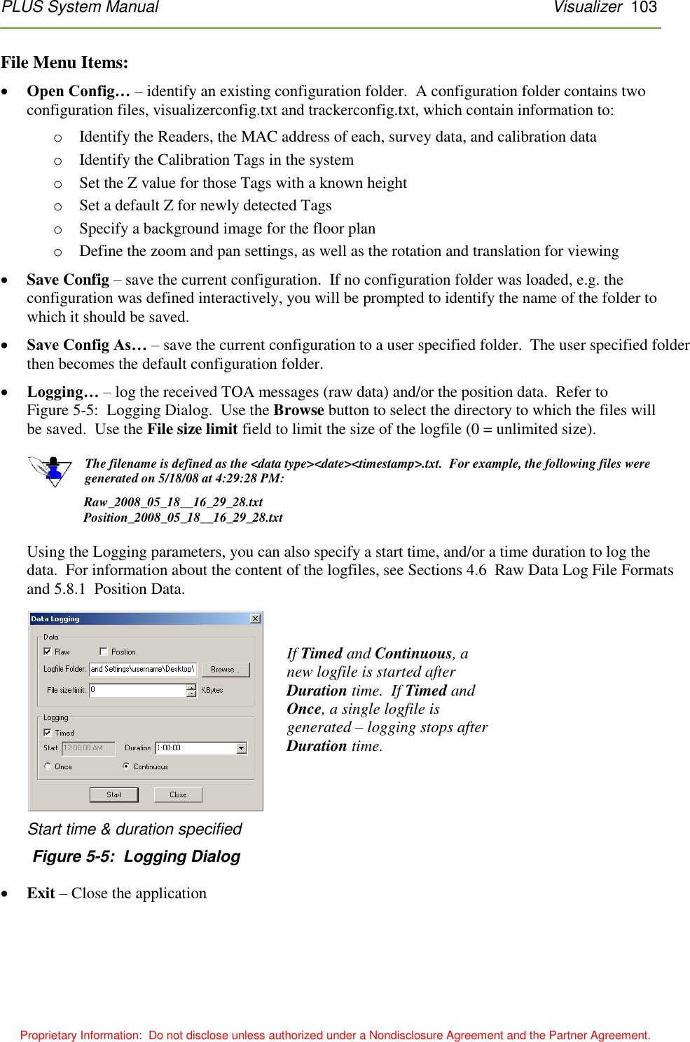
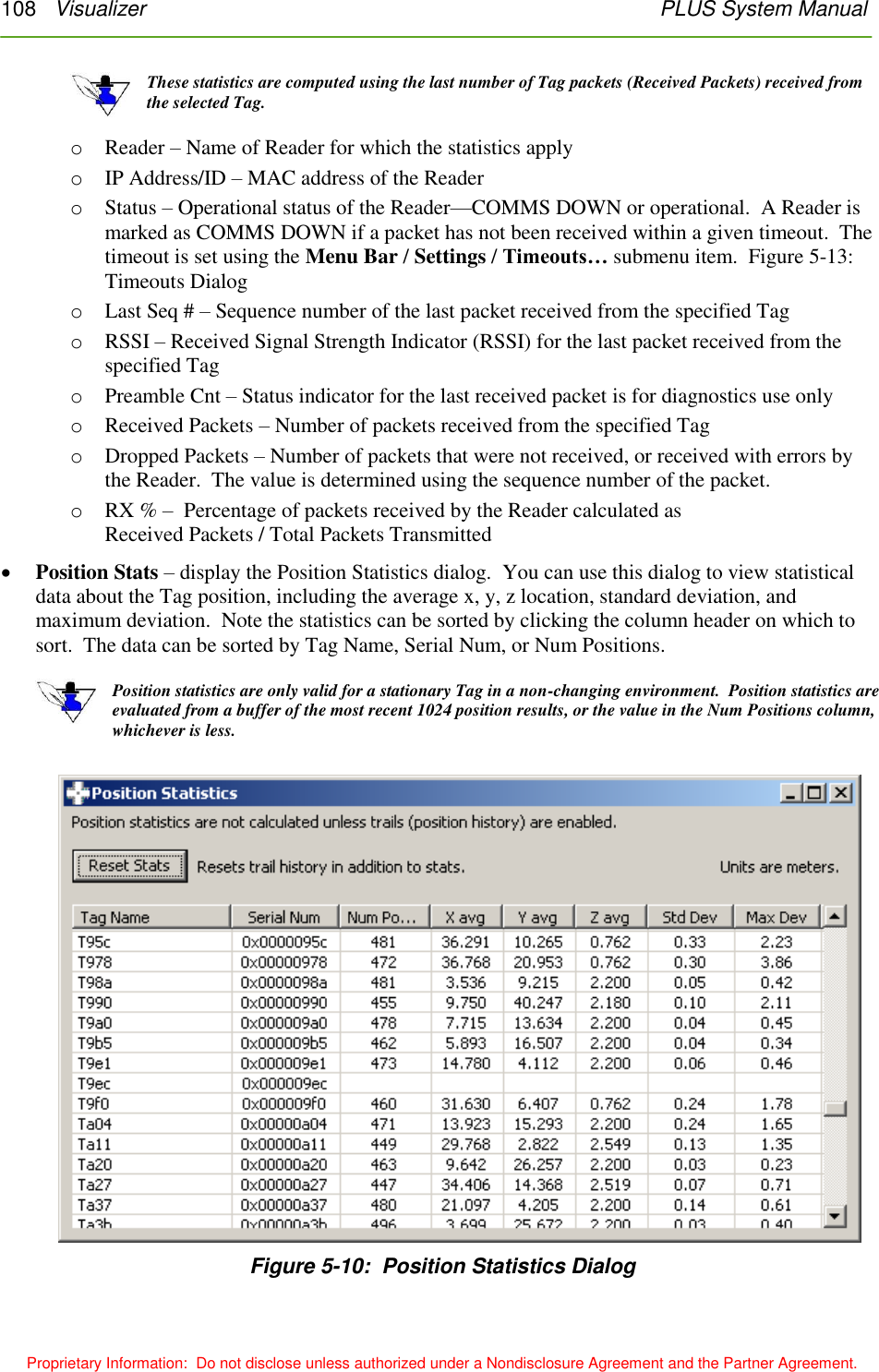
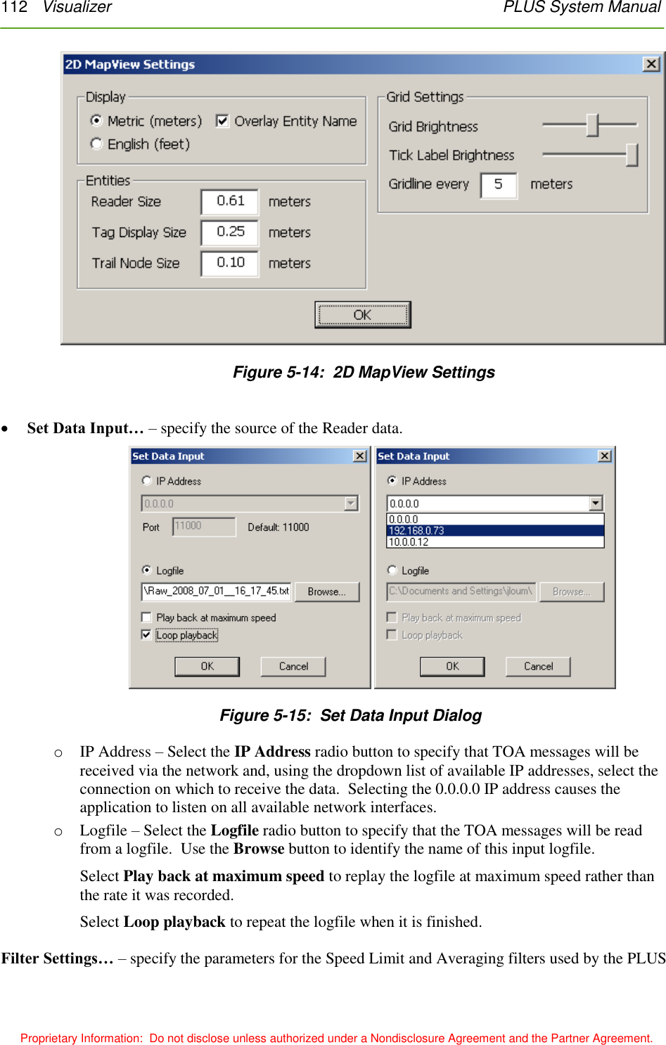
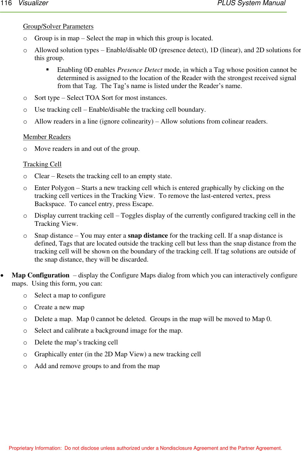
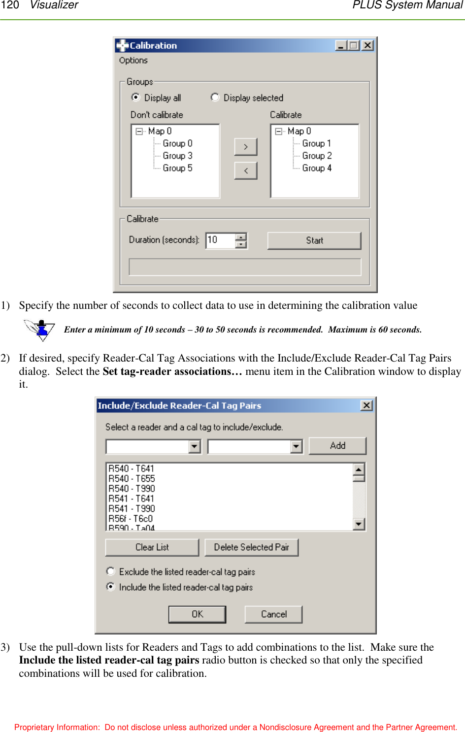
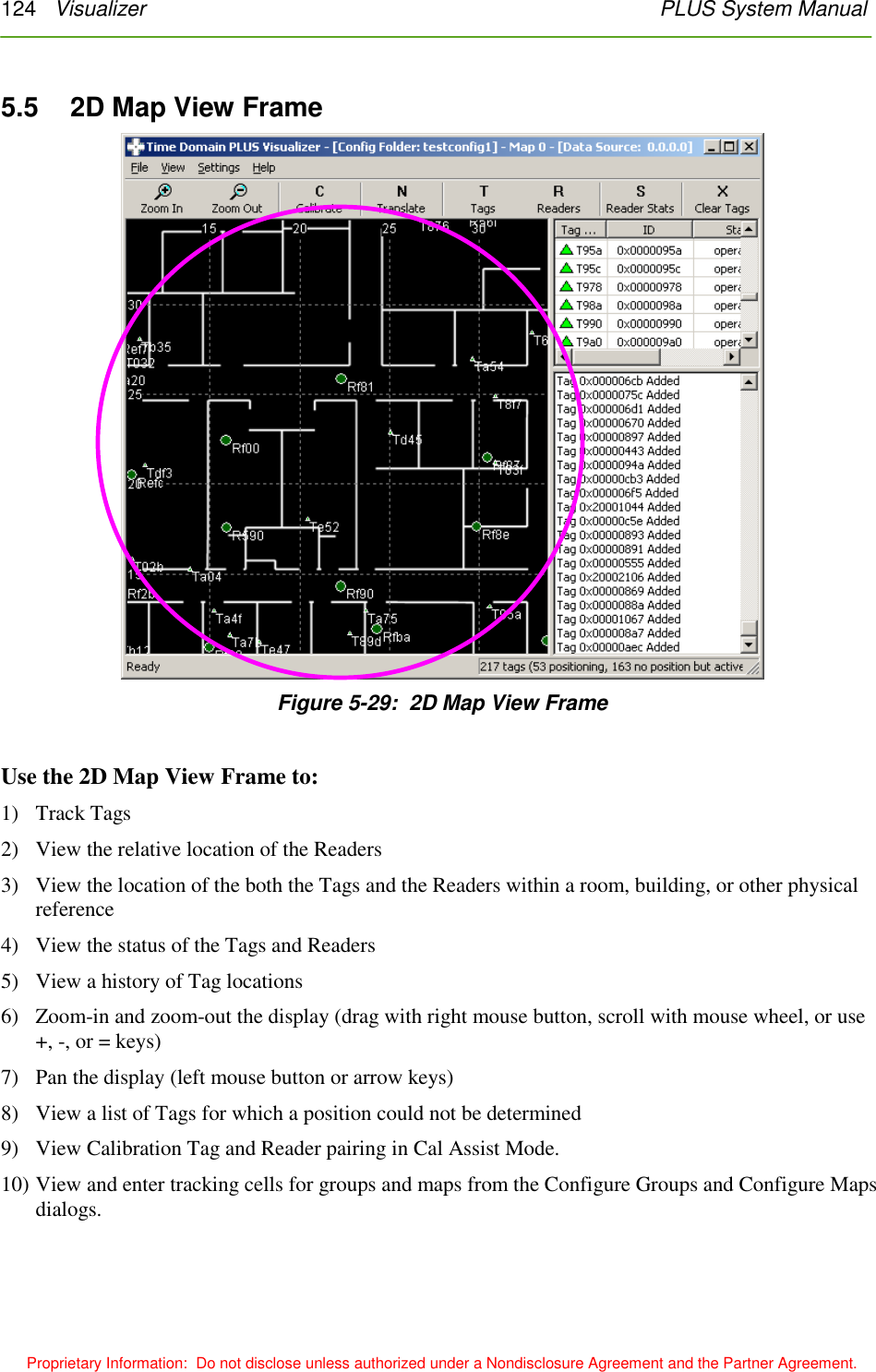
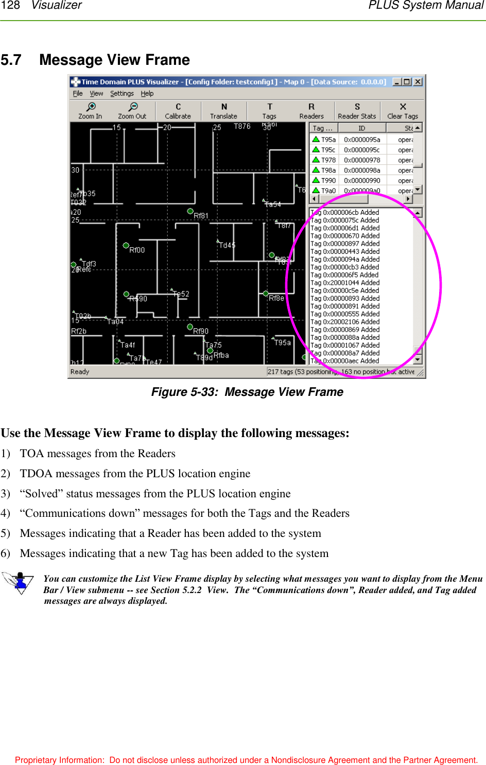
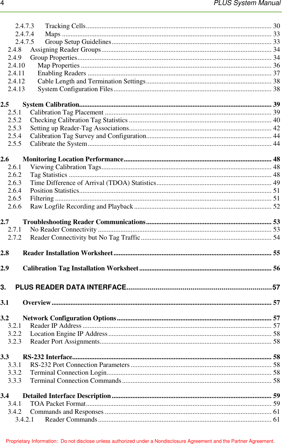
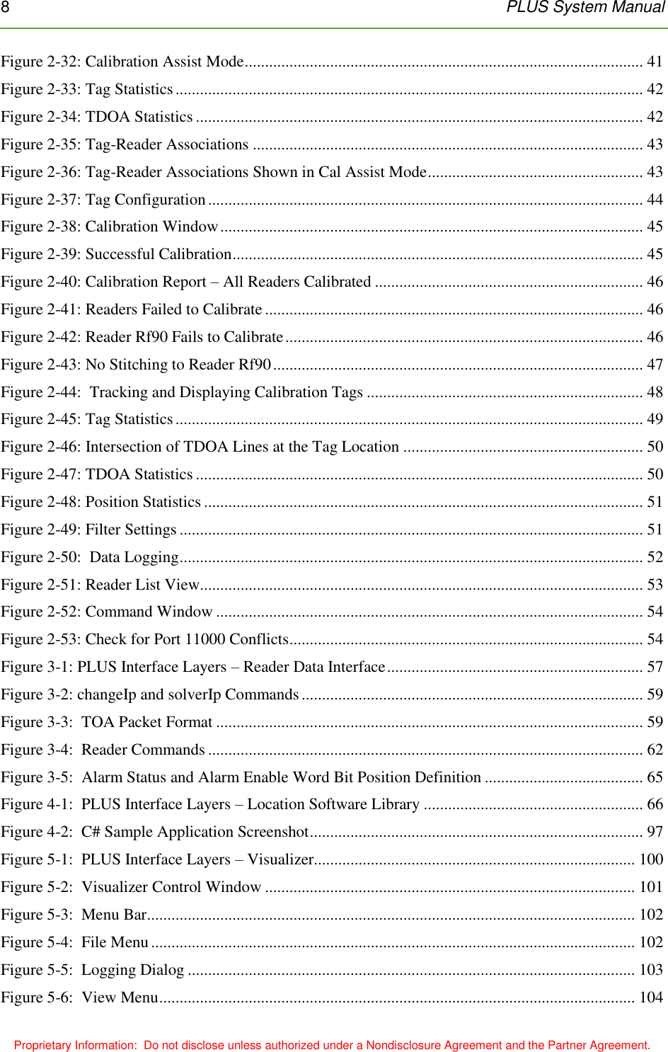
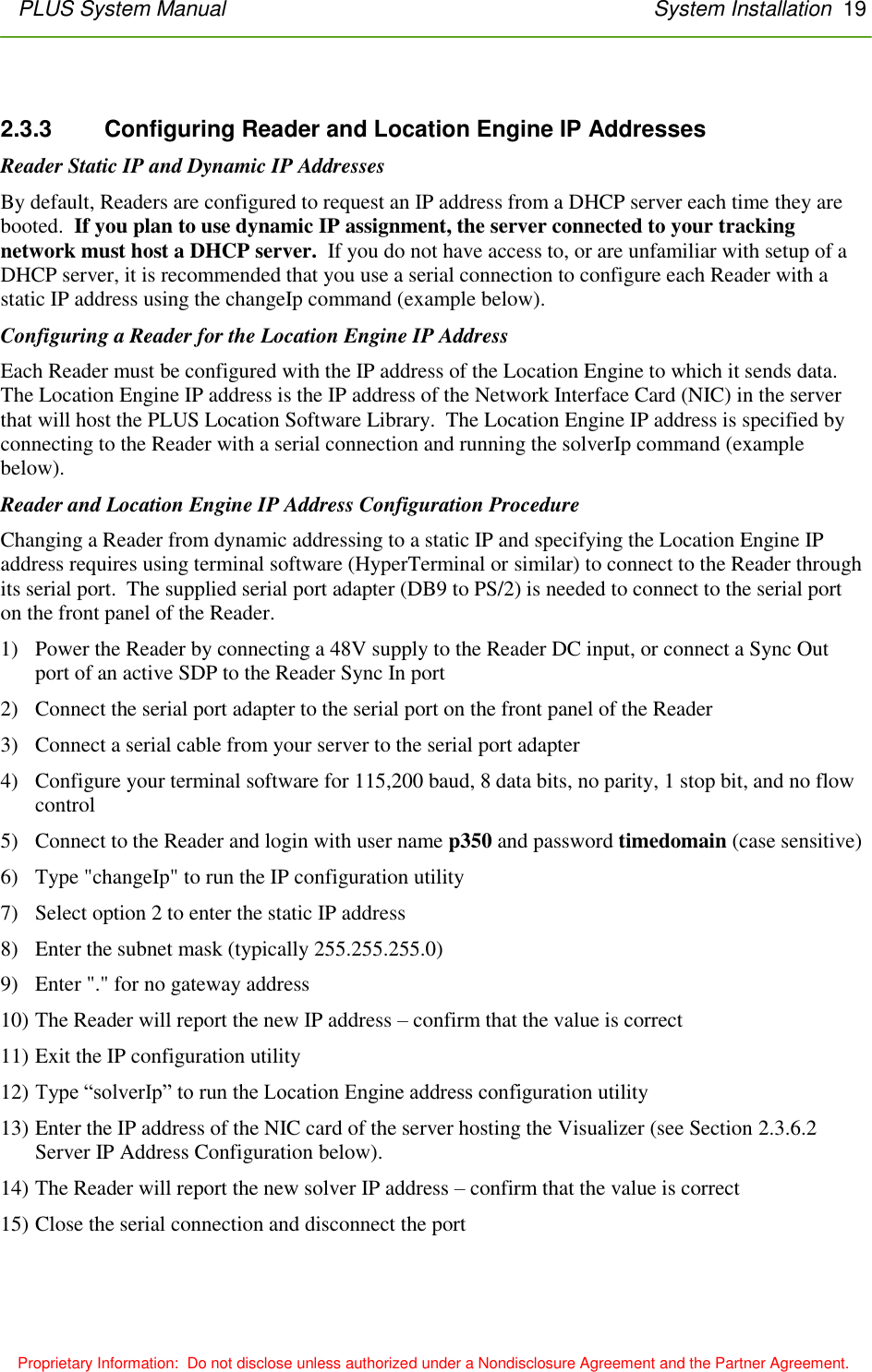
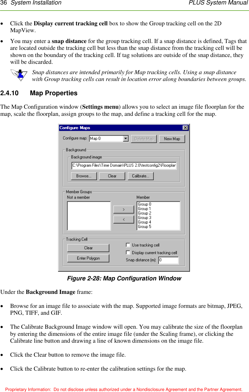
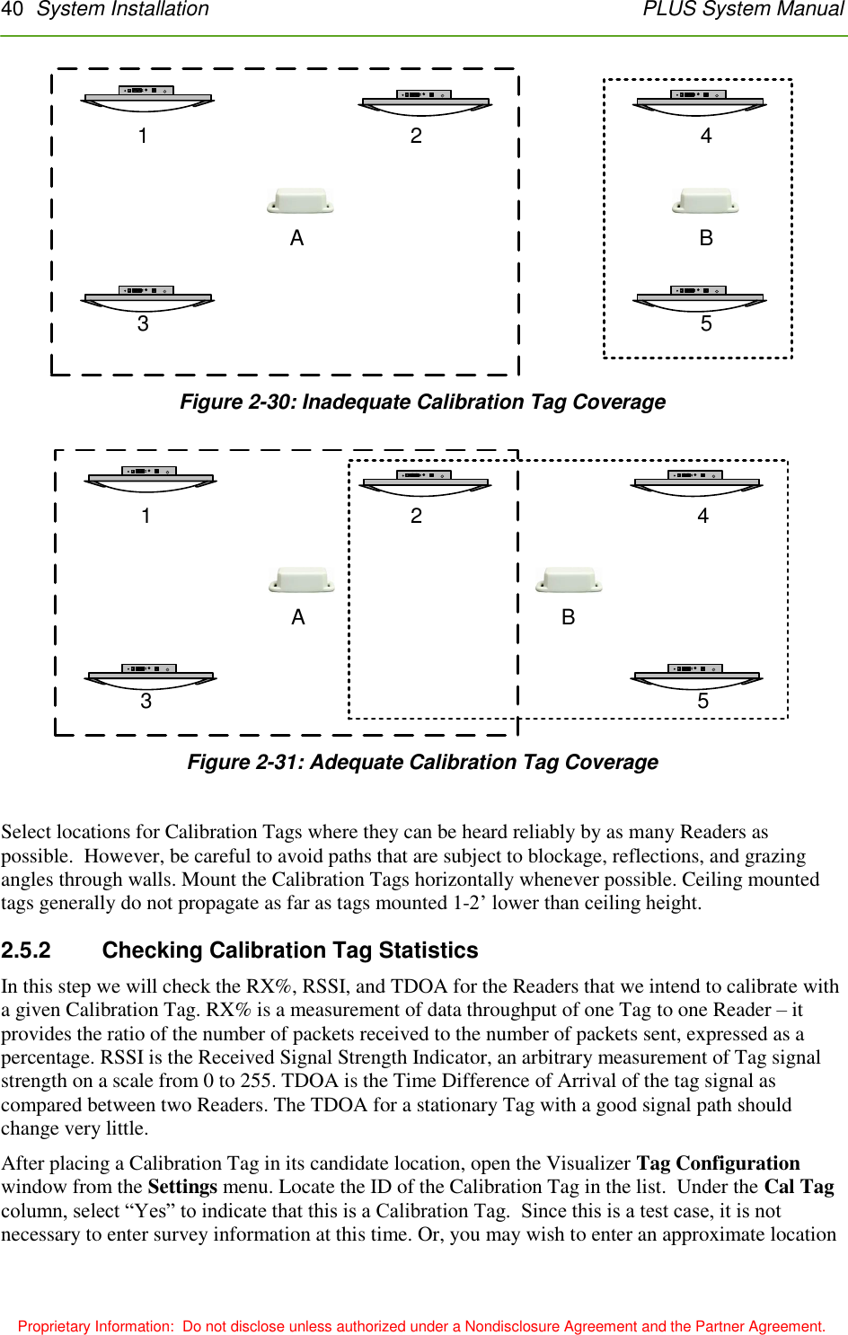
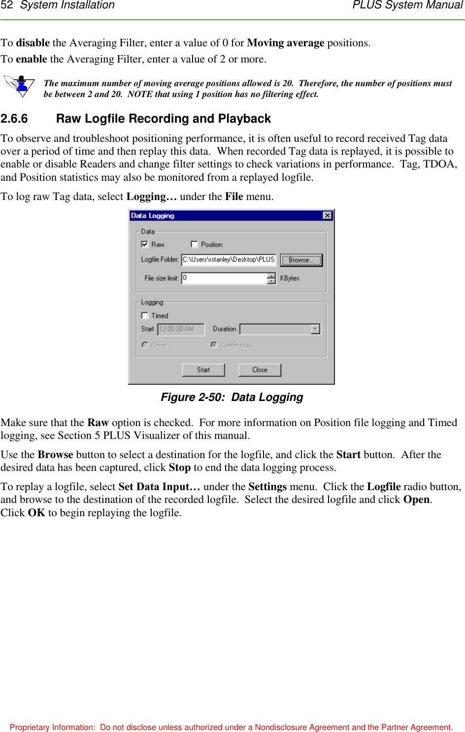
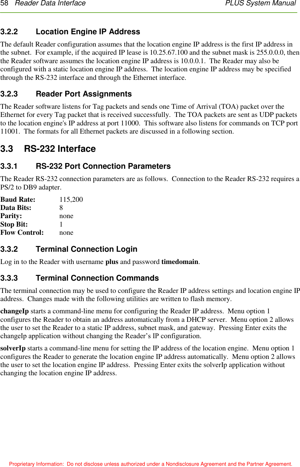
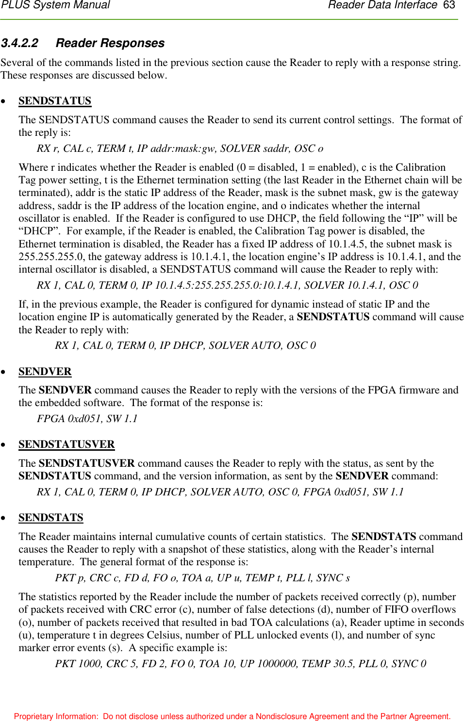
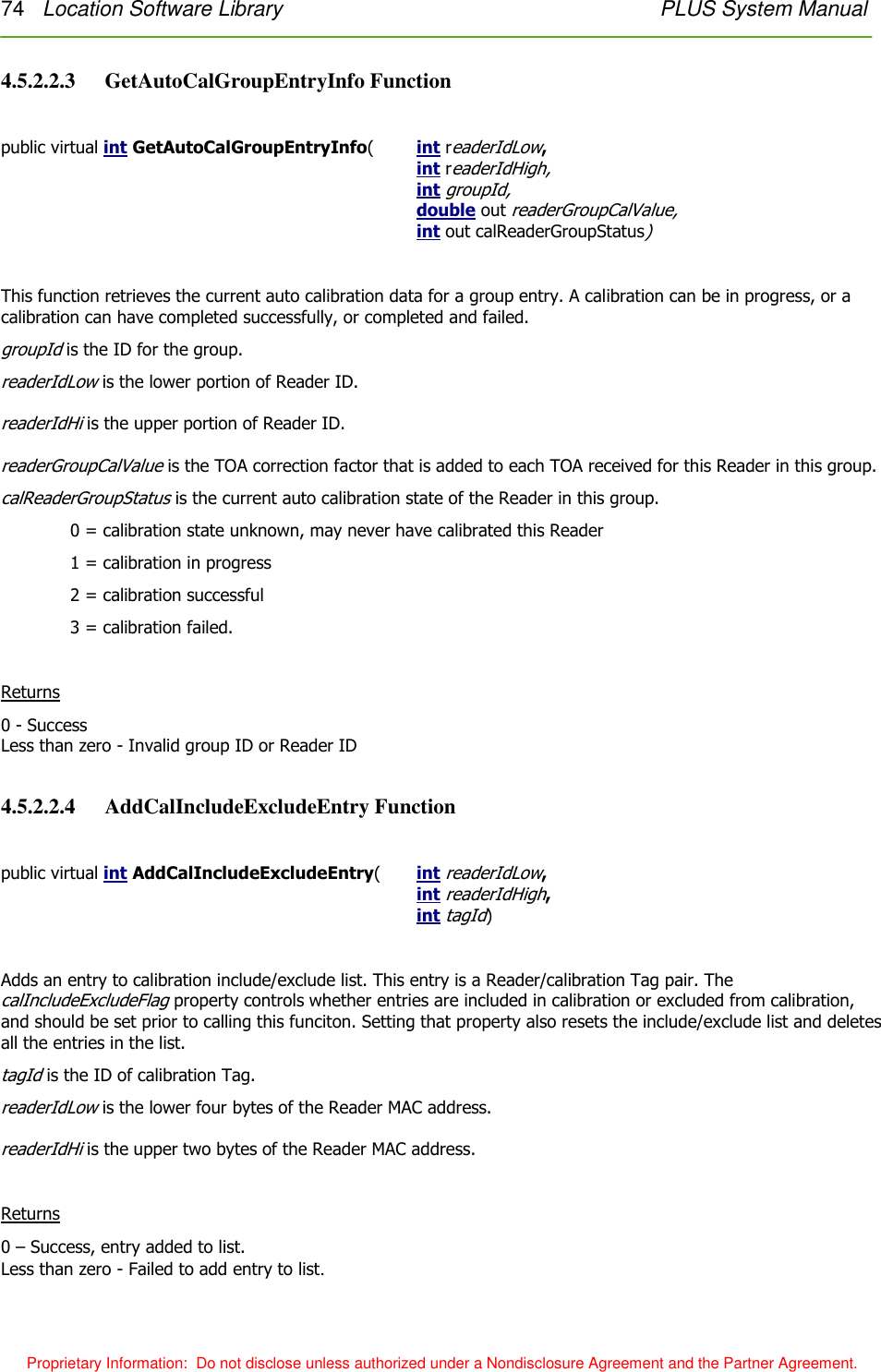
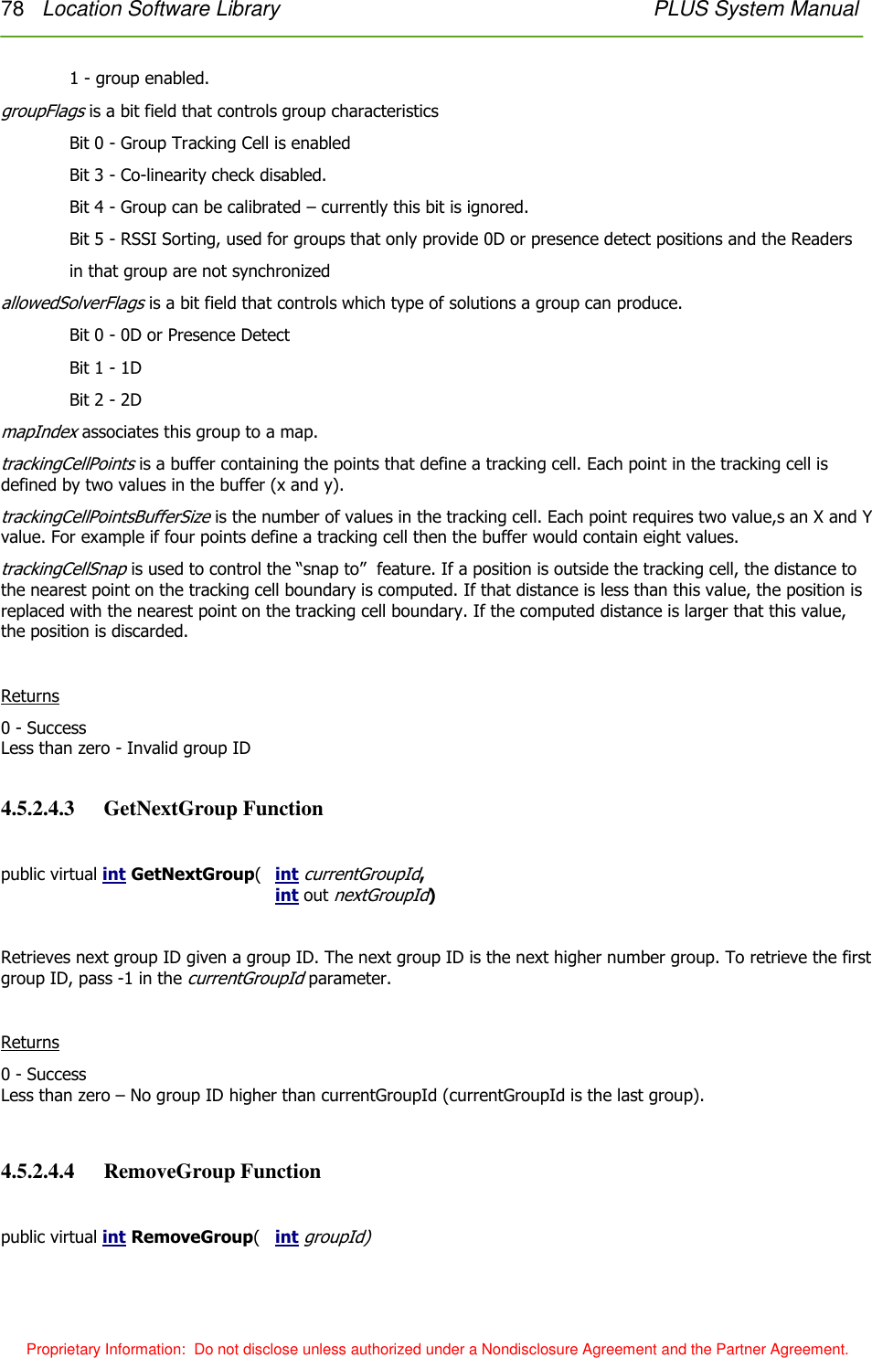
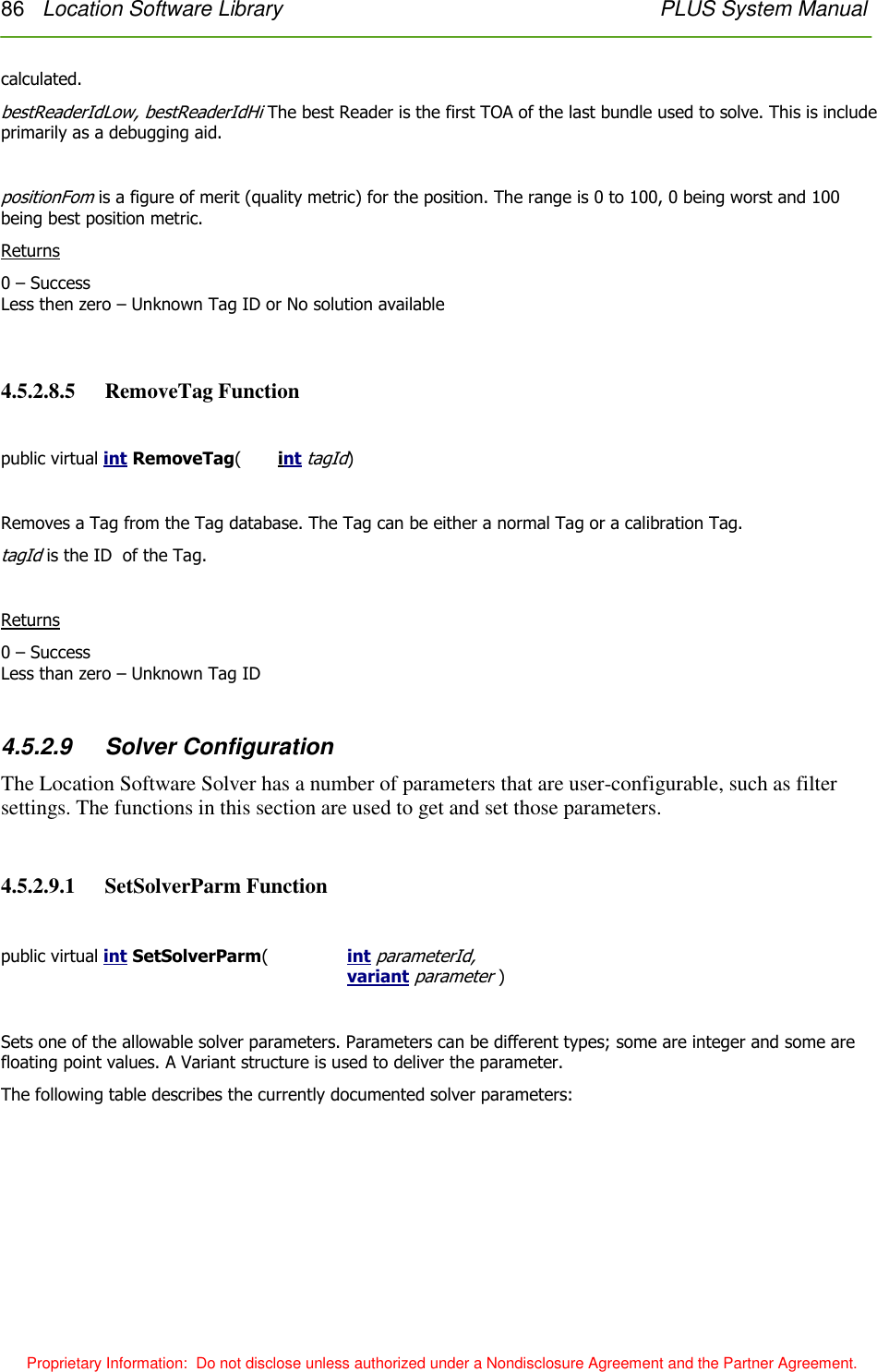
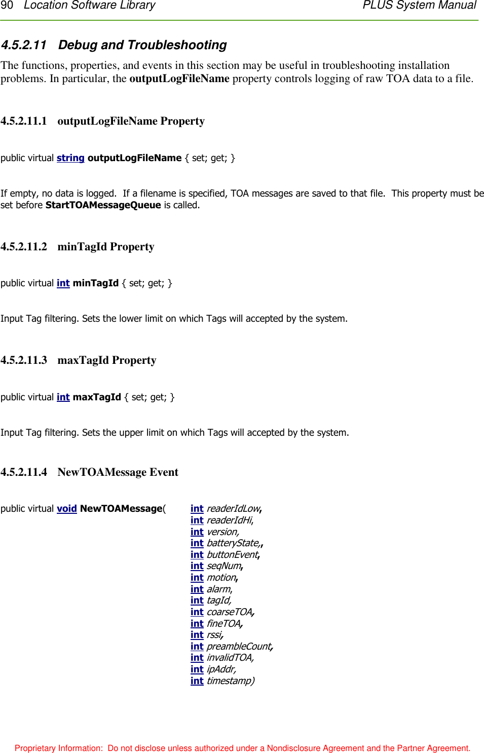
![62 Reader Data Interface PLUS System Manual Proprietary Information: Do not disclose unless authorized under a Nondisclosure Agreement and the Partner Agreement. Command Meaning RX 1 Enable the Reader. This causes the Reader to start listening to Tag packets. The Reader is automatically enabled at startup. RX 0 Disable Reader. The Reader will stop listening for Tag packets. CAL 1 Enable power to Calibration Tag. CAL 0 Disable power to Calibration Tag. Power to the Calibration Tag is disabled at startup. IP DHCP Configure the Reader to acquire its IP address via DHCP. IP ipaddr:mask[:gw] Configure the Reader to use the static IP address ipaddr, subnet mask mask, and gateway gw. The gateway parameter is optional. SOLVER AUTO Configure the Reader to generate the location engine IP address based on the Reader’s IP address and netmask. SOLVER addr Set IP address of location engine to addr. The Reader sends all TOA packets to the location engine’s IP address. OSC 1 Enable the internal oscillator. The internal oscillator should be enabled when Reader is not connected to a SDP. OSC 0 Disable the internal oscillator. The internal oscillator should be disabled when Reader is connected to a SDP. REBOOT Reboot Reader. SENDSTATUS Causes Reader to reply with current status. SENDVER Causes Reader to reply with software and firmware version information. SENDSTATUSVER Causes Reader to reply with status and version information. SENDSTATS Causes Reader to send statistics. CLEARSTATS Causes Reader to reset statistics fields to 0. SENDALARMSTATUS Causes Reader to send alarm status word. SENDALARMENABLE Causes Reader to send alarm enable word. SETALARMENABLE a Sets Reader’s alarm enable word to a. CLEARALARM a Clears alarm condition(s) a in Reader. Figure 3-4: Reader Commands The values specified by the IP, SOLVER, OSC, and SETALARMENABLE commands are stored in flash and are persistent across reboots.](https://usermanual.wiki/Humatics/PLUS-0309/User-Guide-1077039-Page-62.png)
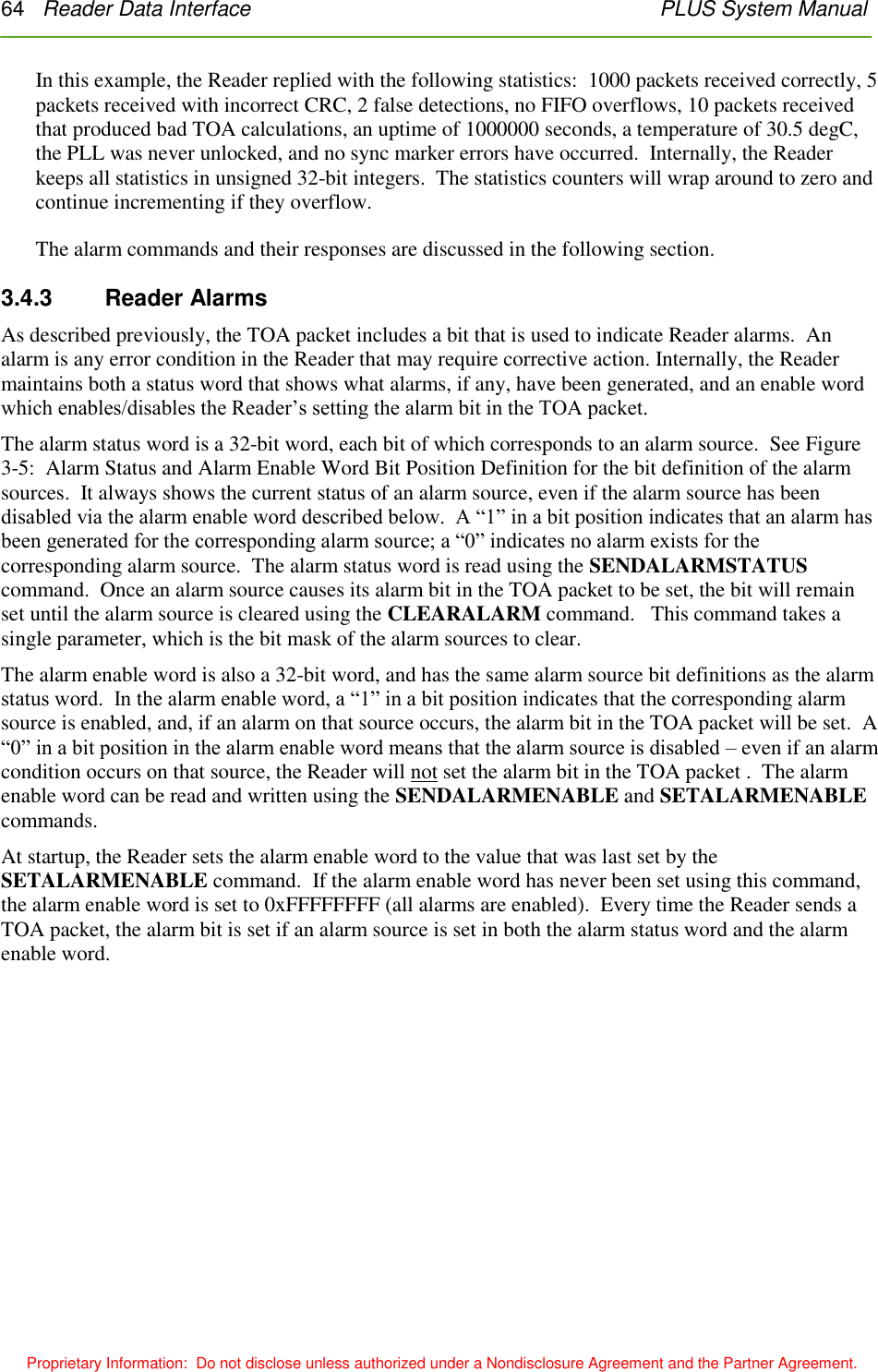
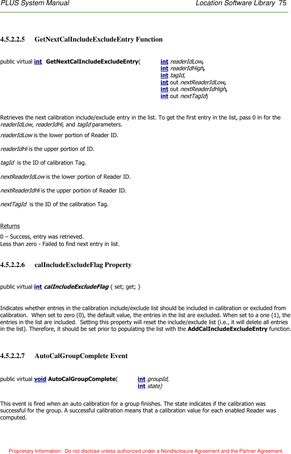
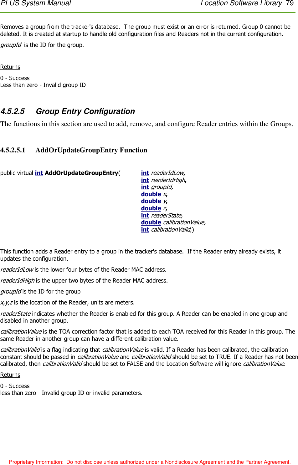
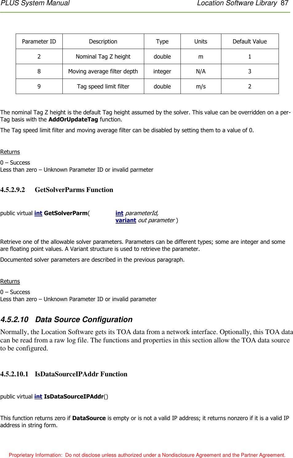
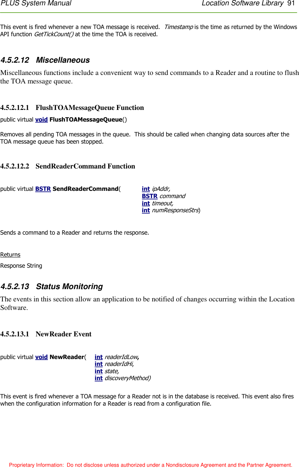
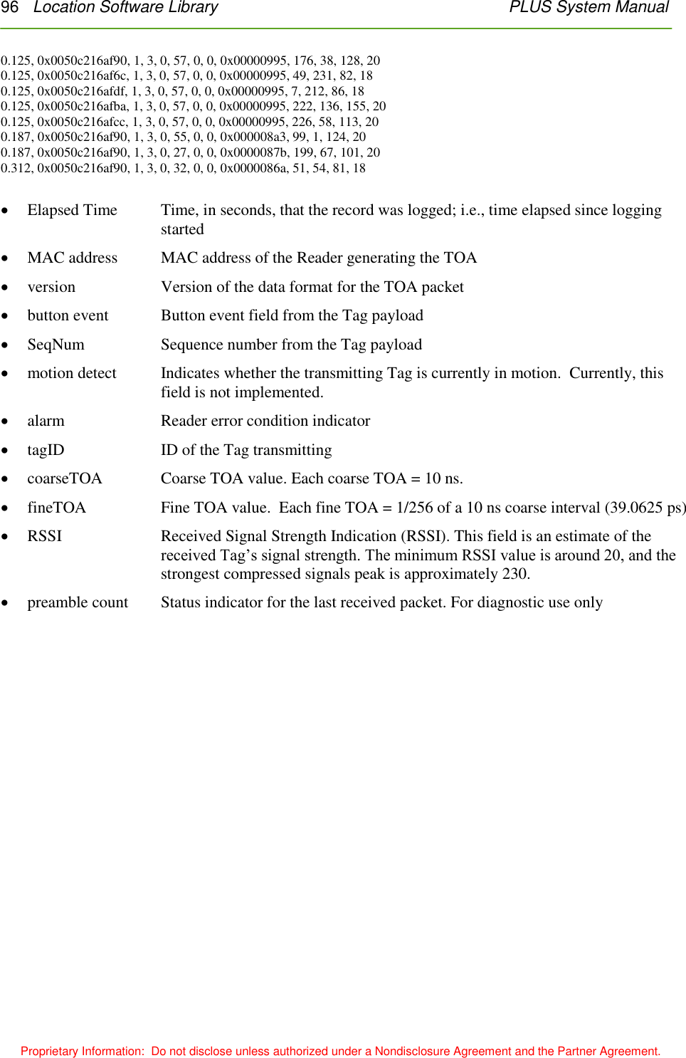
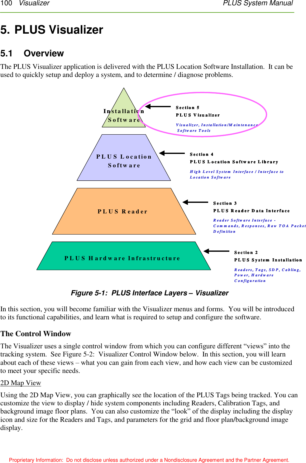
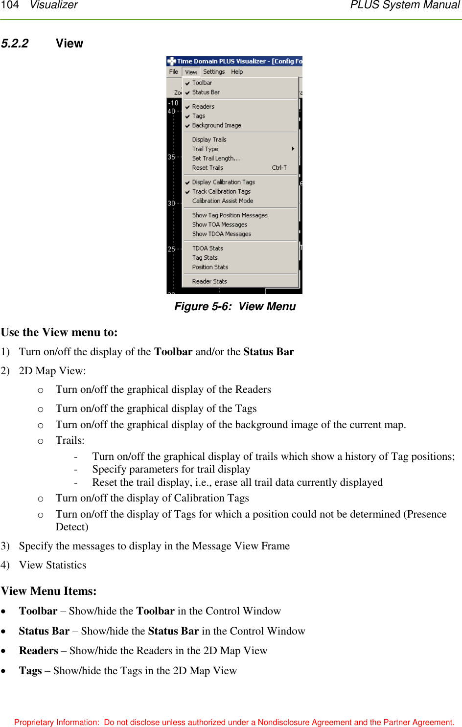
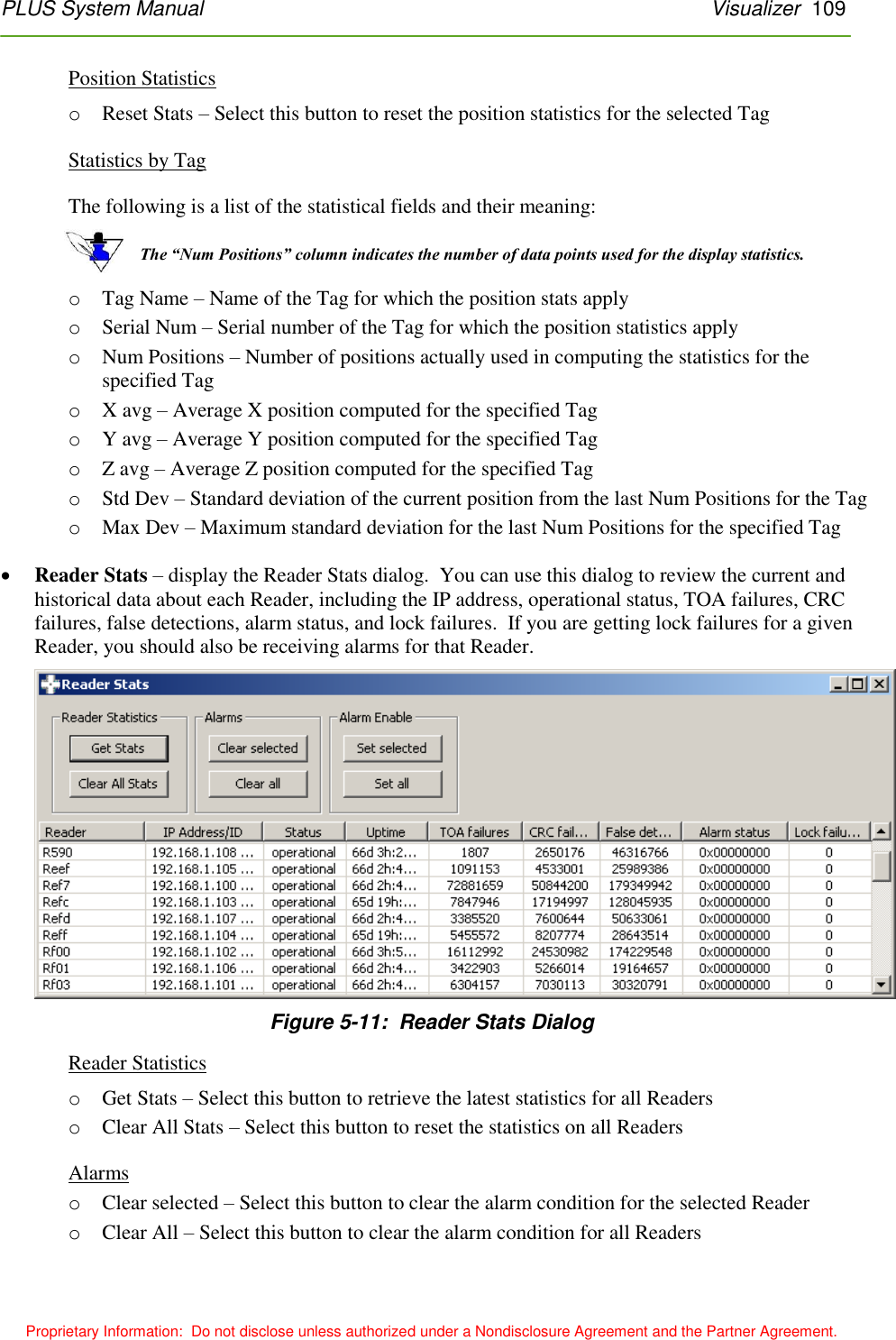
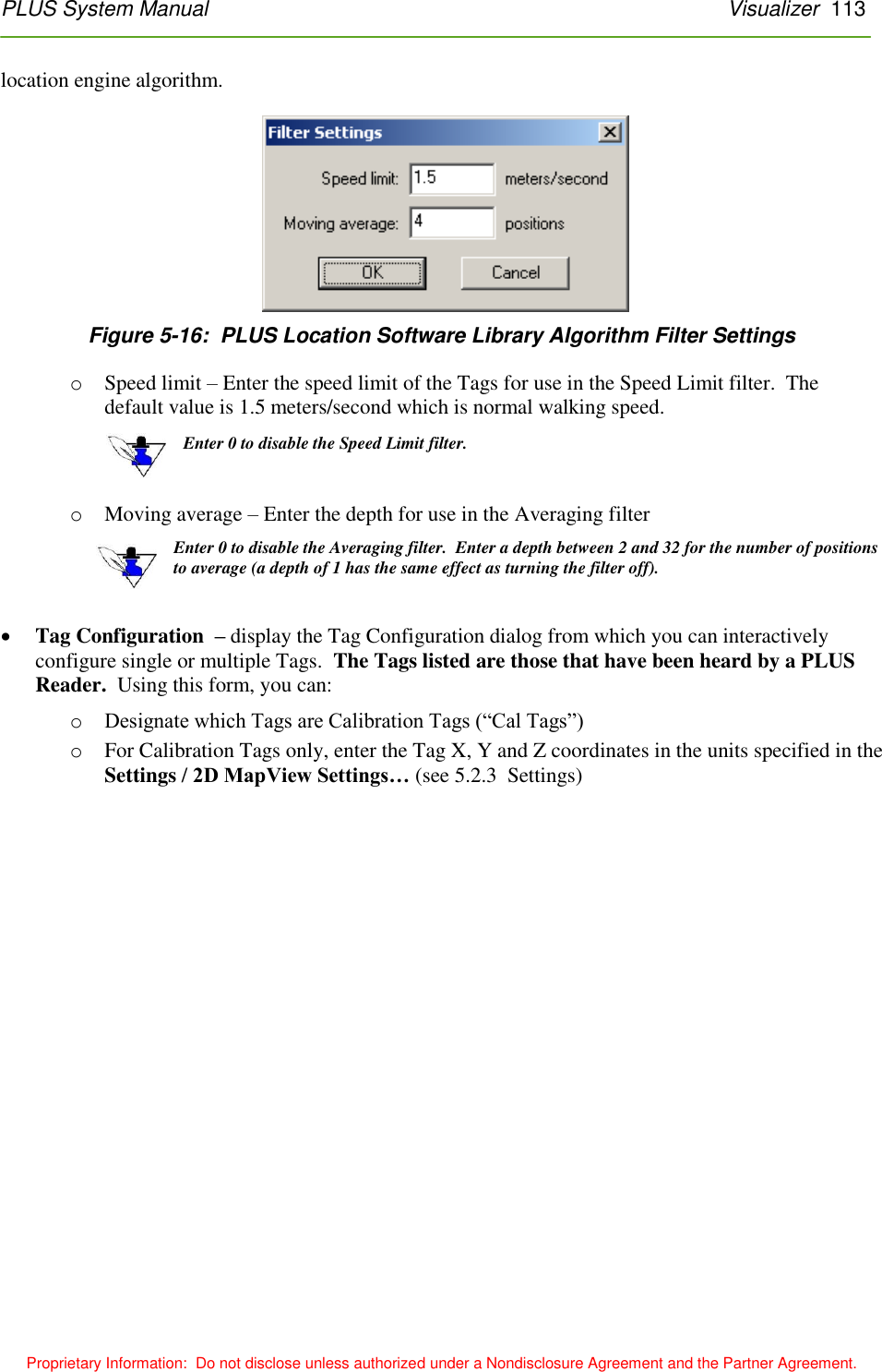
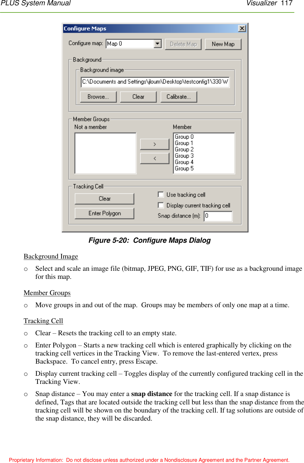
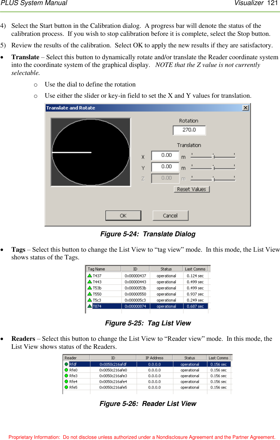
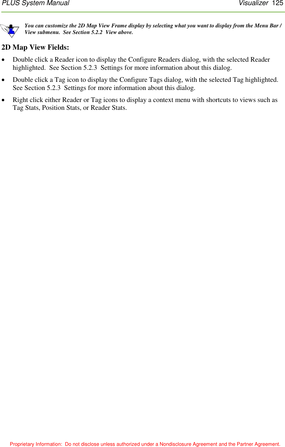
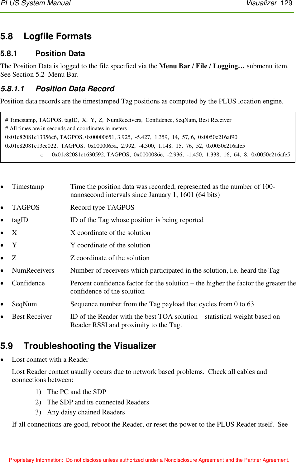
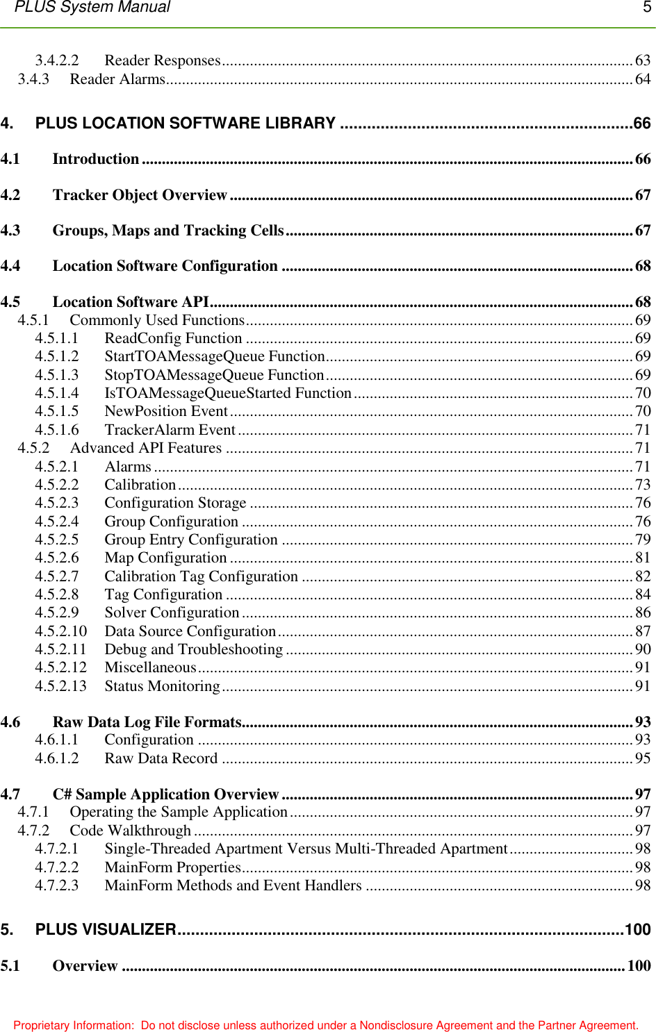
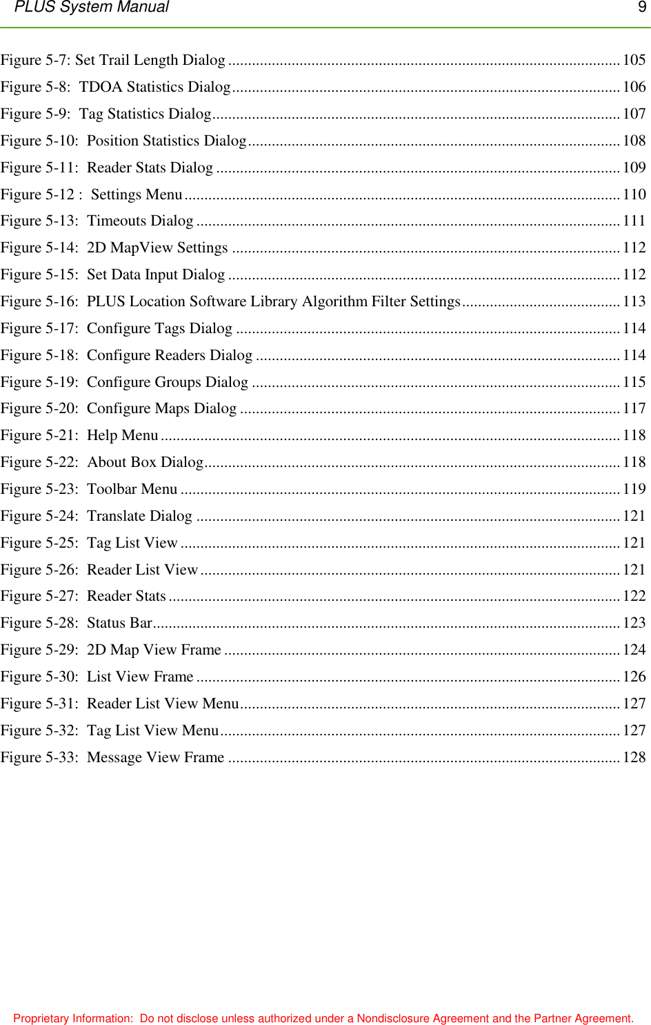
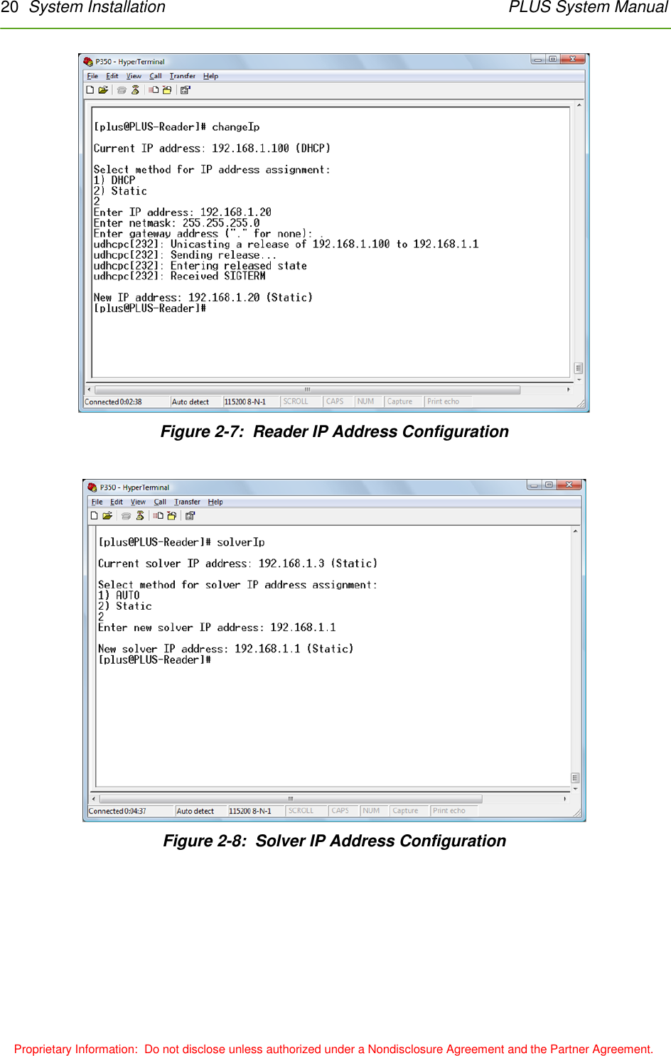
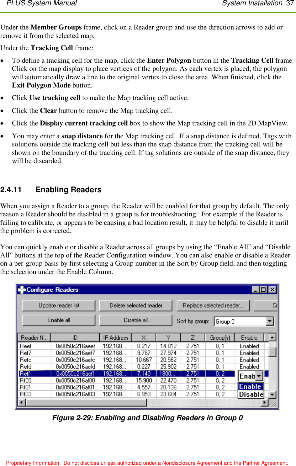
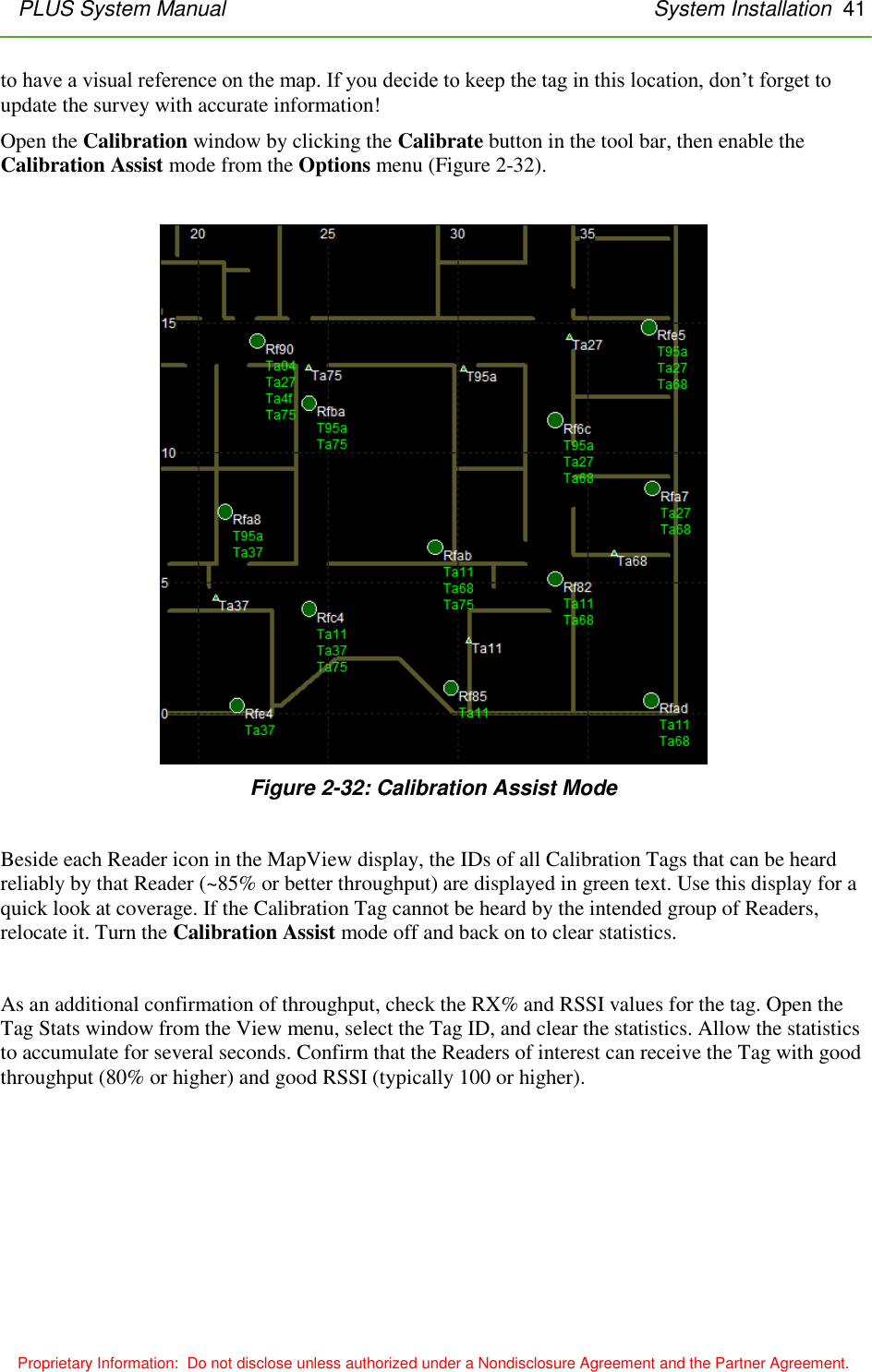
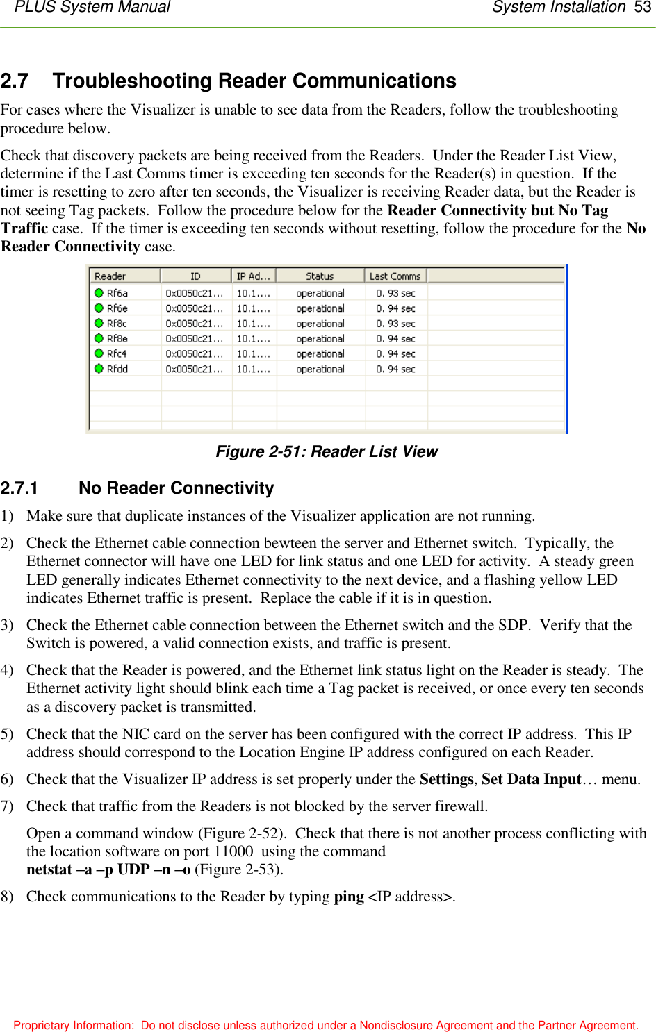
![PLUS System Manual Location Software Library 93 Proprietary Information: Do not disclose unless authorized under a Nondisclosure Agreement and the Partner Agreement. 4.6 Raw Data Log File Formats The file itself is actually divided into two sections – Configuration and Data. By capturing both the system configuration and the raw TOA messages, the information needed for playback is encapsulated into one logfile for use as a data input source. 4.6.1.1 Configuration ## CONFIGURATION # 080711,152111,13780.5, VERSION 2.0.0 # configuration version number to detect old version # MAP Flags bit 0 = Map includes Tracking Cell #MAP mapIndex, Flags, SnapDist, [trackcell data] MAP 0, 0x1, 2.00 [0.00,0.00;0.00,46.00;38.50,46.00;38.50,0.00;0.00,0.00] # GROUP state 0 disabled, 1 enabled # GROUP Flags bit 0 = Group Tracking Cell is enabled # bit 1 = not used should be set to 0 # bit 2 = not used should be set to 0 # bit 3 = Group co-linearity check disabled # bit 4 = Group can be calibrated # bit 5 = Group uses RSSI sorting (for non-synced 0d group) # # GROUP SolverTypes # bit 0 = 0D # bit 1 = 1D # bit 2 = 2D (polar) # # mapIndex Map Index for this group # # SnapDist distance outside of trackingcell where points converted to nearest points # # #GROUP ID State, Flags, SolverTypes, mapIndex, SnapDist, TrackingCellData GROUP 0, 1, 0x10, 0x4, 0, 0.00 # READER: ID (MAC address) X, Y, Z, Calibration, state group](https://usermanual.wiki/Humatics/PLUS-0309/User-Guide-1077039-Page-93.png)