Humatics PLUS-0309 PLUS Name Tag User Manual Manual
TDC Acquisition Holdings Inc. PLUS Name Tag Manual
Humatics >
Manual

Time Domain Corporation
Cummings Research Park
330 Wynn Drive, Suite 300
Huntsville, AL 35805 USA
http://www.timedomain.com
Tel: +1.256.922.9229
+1.888.826.8378
Fax: +1.256.922.0387
P320-0239
July 2008
Precision Location
Ultra Wideband System
( P L U S ™ )
Precision Real-Time Location System
System Manual
System Manua l
Precision Real-Time Location System

2 PLUS System Manual
Proprietary Information: Do not disclose unless authorized under a Nondisclosure Agreement and the Partner Agreement.
Nondisclosure Provisions
This manual is confidential and is governed by the terms of the Nondisclosure Agreement and the Partner Agreement
currently in effect between the parties.
Copyright
©2001-2008 Time Domain Corporation. All rights reserved.
Trademarks
Time Domain® and PulsON® are registered trademarks of Time Domain Corporation. Ethernet® is a registered trademark
of Xerox Corporation. ―PulsON Triangle‖ logo and PLUS™ are trademarks of Time Domain Corporation. Any
trademarks, trade names, service marks or service names owned or registered by any other company and used in this manual
are the property of its respective company.
Rights
Rights to use this documentation are set forth in the Terms and Conditions accompanying the PLUS™ hardware.
Product Safety Notice
This device is listed under the ETL mark as Information Technology Equipment.
Regulatory Notice
U.S. Operation: This device complies with Part 15 of the FCC Rules. Operation is subject to the following
conditions: (1) this device may not cause harmful interference, and (2) this device must accept any interference
received, including interference that may cause undesired operation. (3) Operation on board an aircraft or a
satellite is prohibited. (4) Devices operating under this section may not be employed for the operation of toys.
Operation in disregard of these conditions is a violation of 47 U.S.C. 301 and could subject the operator to
serious legal penalties. Disassembling or modifying the unit will void FCC compliance and void Time Domain
warranty provisions.
Non-U.S. Operation: PulsON® technology has not been authorized for use or commercial exploitation under
the regulations of any non-US government agency. Please confer with your government’s regulatory agency to
ensure proper authorizations are obtained.

PLUS System Manual 3
Proprietary Information: Do not disclose unless authorized under a Nondisclosure Agreement and the Partner Agreement.
Table of Contents
1. OVERVIEW .................................................................................................................10
1.1 Manual Contents ................................................................................................................... 11
1.2 PLUS System Products ......................................................................................................... 11
1.2.1 Synchronization Distribution Panel .................................................................................... 11
1.2.2 Reader ................................................................................................................................. 11
1.2.3 Asset Tag ............................................................................................................................ 12
1.2.4 Antenna ............................................................................................................................... 12
1.2.5 Location Software ............................................................................................................... 12
1.3 Additional Components and Peripherals ............................................................................ 12
1.3.1 Visualizer ............................................................................................................................ 12
1.3.2 Location Software Server .................................................................................................... 12
1.3.3 Ethernet Cable ..................................................................................................................... 13
1.3.4 PS/2 Serial Adapter Cable ................................................................................................... 13
1.3.5 Reader Power Supplies ....................................................................................................... 13
1.3.6 Ethernet Switch ................................................................................................................... 13
2. PLUS SYSTEM INSTALLATION ................................................................................14
2.1 Pre-Installation Site Survey .................................................................................................. 15
2.2 Reader Placement and Wiring Diagram ............................................................................. 17
2.3 Installation Overview ............................................................................................................ 18
2.3.1 Unpacking and Inspecting Hardware .................................................................................. 18
2.3.2 Installing and Powering the SDP ........................................................................................ 18
2.3.3 Configuring Reader and Location Engine IP Addresses ..................................................... 19
2.3.4 Ceiling Installation of Readers and Antennas ..................................................................... 21
2.3.4.1 Mounting Readers to Antennas .................................................................................. 21
2.3.4.2 Installing Reader / Hinged Antenna Assemblies ........................................................ 21
2.3.5 Surveying Readers and Generating Coordinates ................................................................. 23
2.3.6 Server Setup and Software Installation ............................................................................... 24
2.3.6.1 Connecting the SDP, Ethernet Switch, and Server ..................................................... 24
2.3.6.2 Server IP Address Configuration ............................................................................... 24
2.3.6.3 Server Firewall Settings ............................................................................................. 25
2.4 Configuring the System Using Visualizer ............................................................................ 26
2.4.1 Workflow ............................................................................................................................ 26
2.4.2 PLUS Visualizer Software Installation ............................................................................... 27
2.4.3 Set Data Input ..................................................................................................................... 28
2.4.4 Check Reader Communications .......................................................................................... 28
2.4.5 Setting English/Metric Units ............................................................................................... 29
2.4.6 Entering Reader Survey Data .............................................................................................. 29
2.4.7 Reader Groups..................................................................................................................... 30
2.4.7.1 Reader Groups Overview ........................................................................................... 30
2.4.7.2 Solution Types ............................................................................................................ 30

4 PLUS System Manual
Proprietary Information: Do not disclose unless authorized under a Nondisclosure Agreement and the Partner Agreement.
2.4.7.3 Tracking Cells ............................................................................................................ 30
2.4.7.4 Maps .......................................................................................................................... 33
2.4.7.5 Group Setup Guidelines ............................................................................................. 33
2.4.8 Assigning Reader Groups ................................................................................................... 34
2.4.9 Group Properties ................................................................................................................. 34
2.4.10 Map Properties ............................................................................................................... 36
2.4.11 Enabling Readers ........................................................................................................... 37
2.4.12 Cable Length and Termination Settings ......................................................................... 38
2.4.13 System Configuration Files ............................................................................................ 38
2.5 System Calibration................................................................................................................ 39
2.5.1 Calibration Tag Placement ................................................................................................. 39
2.5.2 Checking Calibration Tag Statistics ................................................................................... 40
2.5.3 Setting up Reader-Tag Associations ................................................................................... 42
2.5.4 Calibration Tag Survey and Configuration......................................................................... 44
2.5.5 Calibrate the System ........................................................................................................... 44
2.6 Monitoring Location Performance ...................................................................................... 48
2.6.1 Viewing Calibration Tags ................................................................................................... 48
2.6.2 Tag Statistics ...................................................................................................................... 48
2.6.3 Time Difference of Arrival (TDOA) Statistics ................................................................... 49
2.6.4 Position Statistics ................................................................................................................ 51
2.6.5 Filtering .............................................................................................................................. 51
2.6.6 Raw Logfile Recording and Playback ................................................................................ 52
2.7 Troubleshooting Reader Communications ......................................................................... 53
2.7.1 No Reader Connectivity ..................................................................................................... 53
2.7.2 Reader Connectivity but No Tag Traffic ............................................................................ 54
2.8 Reader Installation Worksheet ............................................................................................ 55
2.9 Calibration Tag Installation Worksheet ............................................................................. 56
3. PLUS READER DATA INTERFACE ........................................................................... 57
3.1 Overview ................................................................................................................................ 57
3.2 Network Configuration Options .......................................................................................... 57
3.2.1 Reader IP Address .............................................................................................................. 57
3.2.2 Location Engine IP Address ............................................................................................... 58
3.2.3 Reader Port Assignments.................................................................................................... 58
3.3 RS-232 Interface.................................................................................................................... 58
3.3.1 RS-232 Port Connection Parameters .................................................................................. 58
3.3.2 Terminal Connection Login ................................................................................................ 58
3.3.3 Terminal Connection Commands ....................................................................................... 58
3.4 Detailed Interface Description ............................................................................................. 59
3.4.1 TOA Packet Format ............................................................................................................ 59
3.4.2 Commands and Responses ................................................................................................. 61
3.4.2.1 Reader Commands ..................................................................................................... 61

PLUS System Manual 5
Proprietary Information: Do not disclose unless authorized under a Nondisclosure Agreement and the Partner Agreement.
3.4.2.2 Reader Responses ....................................................................................................... 63
3.4.3 Reader Alarms..................................................................................................................... 64
4. PLUS LOCATION SOFTWARE LIBRARY .................................................................66
4.1 Introduction ........................................................................................................................... 66
4.2 Tracker Object Overview ..................................................................................................... 67
4.3 Groups, Maps and Tracking Cells ....................................................................................... 67
4.4 Location Software Configuration ........................................................................................ 68
4.5 Location Software API .......................................................................................................... 68
4.5.1 Commonly Used Functions ................................................................................................. 69
4.5.1.1 ReadConfig Function ................................................................................................. 69
4.5.1.2 StartTOAMessageQueue Function ............................................................................. 69
4.5.1.3 StopTOAMessageQueue Function ............................................................................. 69
4.5.1.4 IsTOAMessageQueueStarted Function ...................................................................... 70
4.5.1.5 NewPosition Event ..................................................................................................... 70
4.5.1.6 TrackerAlarm Event ................................................................................................... 71
4.5.2 Advanced API Features ...................................................................................................... 71
4.5.2.1 Alarms ........................................................................................................................ 71
4.5.2.2 Calibration .................................................................................................................. 73
4.5.2.3 Configuration Storage ................................................................................................ 76
4.5.2.4 Group Configuration .................................................................................................. 76
4.5.2.5 Group Entry Configuration ........................................................................................ 79
4.5.2.6 Map Configuration ..................................................................................................... 81
4.5.2.7 Calibration Tag Configuration ................................................................................... 82
4.5.2.8 Tag Configuration ...................................................................................................... 84
4.5.2.9 Solver Configuration .................................................................................................. 86
4.5.2.10 Data Source Configuration ......................................................................................... 87
4.5.2.11 Debug and Troubleshooting ....................................................................................... 90
4.5.2.12 Miscellaneous ............................................................................................................. 91
4.5.2.13 Status Monitoring ....................................................................................................... 91
4.6 Raw Data Log File Formats.................................................................................................. 93
4.6.1.1 Configuration ............................................................................................................. 93
4.6.1.2 Raw Data Record ....................................................................................................... 95
4.7 C# Sample Application Overview ........................................................................................ 97
4.7.1 Operating the Sample Application ...................................................................................... 97
4.7.2 Code Walkthrough .............................................................................................................. 97
4.7.2.1 Single-Threaded Apartment Versus Multi-Threaded Apartment ............................... 98
4.7.2.2 MainForm Properties .................................................................................................. 98
4.7.2.3 MainForm Methods and Event Handlers ................................................................... 98
5. PLUS VISUALIZER ................................................................................................... 100
5.1 Overview .............................................................................................................................. 100

6 PLUS System Manual
Proprietary Information: Do not disclose unless authorized under a Nondisclosure Agreement and the Partner Agreement.
5.2 Menu Bar ............................................................................................................................. 102
5.2.1 File .................................................................................................................................... 102
5.2.2 View ................................................................................................................................. 104
5.2.3 Settings ............................................................................................................................. 110
5.2.4 Help .................................................................................................................................. 118
5.3 Toolbar ................................................................................................................................. 119
5.4 Status Bar ............................................................................................................................ 123
5.5 2D Map View Frame ........................................................................................................... 124
5.6 List View Frame .................................................................................................................. 126
5.7 Message View Frame .......................................................................................................... 128
5.8 Logfile Formats ................................................................................................................... 129
5.8.1 Position Data .................................................................................................................... 129
5.8.1.1 Position Data Record ............................................................................................... 129
5.9 Troubleshooting the Visualizer .......................................................................................... 129

PLUS System Manual 7
Proprietary Information: Do not disclose unless authorized under a Nondisclosure Agreement and the Partner Agreement.
Table of Figures
Figure 1-1 : PLUS SDP, Readers, and Tags ......................................................................................... 10
Figure 1-2 : PLUS Interfaces ............................................................................................................... 10
Figure 2-1: Hardware Connections for a Four-Reader System ........................................................... 14
Figure 2-2: Hardware Placement for a Four-Reader System............................................................... 14
Figure 2-3: Equilateral Triangle Reader Geometry .............................................................................. 16
Figure 2-4: Right Triangle Reader Geometry....................................................................................... 16
Figure 2-5: One through Three Readers per Chain ............................................................................. 17
Figure 2-6: Four through Six Readers Per Chain ................................................................................ 17
Figure 2-7: Reader IP Address Configuration ..................................................................................... 20
Figure 2-8: Solver IP Address Configuration ...................................................................................... 20
Figure 2-9: Reader Connection ........................................................................................................... 21
Figure 2-10: Antenna Frame and Drop Panel ...................................................................................... 21
Figure 2-11: Frame Orientation ........................................................................................................... 21
Figure 2-12: Drop Panel Installation (shown with no Reader mounted) ............................................. 22
Figure 2-13: Closed Panel .................................................................................................................... 22
Figure 2-14: Unterminated Ethernet Cables ........................................................................................ 23
Figure 2-15: PLUS Reader Installation Worksheet .............................................................................. 23
Figure 2-16: TCP/IP Properties ........................................................................................................... 24
Figure 2-17: PLUS Configuration Workflow ....................................................................................... 26
Figure 2-18: Visualizer Application .................................................................................................... 27
Figure 2-19: Set Data Input .................................................................................................................. 28
Figure 2-20: Reader Communications .................................................................................................. 28
Figure 2-21: Setting English/Metric Units ........................................................................................... 29
Figure 2-22: Reader Configuration Window ........................................................................................ 29
Figure 2-23: Tracking Cell for a Four-Reader Group .......................................................................... 31
Figure 2-24: Group Tracking Cell with Boundary Margin .................................................................. 32
Figure 2-25: Tracking Cell Used to Filter Ambiguous Solutions......................................................... 32
Figure 2-26: Assigning Reader Groups ................................................................................................ 34
Figure 2-27: Group Configuration Window ......................................................................................... 35
Figure 2-28: Map Configuration Window ............................................................................................ 36
Figure 2-29: Enabling and Disabling Readers in Group 0 ................................................................... 37
Figure 2-30: Inadequate Calibration Tag Coverage ............................................................................. 40
Figure 2-31: Adequate Calibration Tag Coverage ............................................................................... 40

8 PLUS System Manual
Proprietary Information: Do not disclose unless authorized under a Nondisclosure Agreement and the Partner Agreement.
Figure 2-32: Calibration Assist Mode .................................................................................................. 41
Figure 2-33: Tag Statistics ................................................................................................................... 42
Figure 2-34: TDOA Statistics .............................................................................................................. 42
Figure 2-35: Tag-Reader Associations ................................................................................................ 43
Figure 2-36: Tag-Reader Associations Shown in Cal Assist Mode ..................................................... 43
Figure 2-37: Tag Configuration ........................................................................................................... 44
Figure 2-38: Calibration Window ........................................................................................................ 45
Figure 2-39: Successful Calibration ..................................................................................................... 45
Figure 2-40: Calibration Report – All Readers Calibrated .................................................................. 46
Figure 2-41: Readers Failed to Calibrate ............................................................................................. 46
Figure 2-42: Reader Rf90 Fails to Calibrate ........................................................................................ 46
Figure 2-43: No Stitching to Reader Rf90 ........................................................................................... 47
Figure 2-44: Tracking and Displaying Calibration Tags .................................................................... 48
Figure 2-45: Tag Statistics ................................................................................................................... 49
Figure 2-46: Intersection of TDOA Lines at the Tag Location ........................................................... 50
Figure 2-47: TDOA Statistics .............................................................................................................. 50
Figure 2-48: Position Statistics ............................................................................................................ 51
Figure 2-49: Filter Settings .................................................................................................................. 51
Figure 2-50: Data Logging .................................................................................................................. 52
Figure 2-51: Reader List View............................................................................................................. 53
Figure 2-52: Command Window ......................................................................................................... 54
Figure 2-53: Check for Port 11000 Conflicts ....................................................................................... 54
Figure 3-1: PLUS Interface Layers – Reader Data Interface ............................................................... 57
Figure 3-2: changeIp and solverIp Commands .................................................................................... 59
Figure 3-3: TOA Packet Format ......................................................................................................... 59
Figure 3-4: Reader Commands ........................................................................................................... 62
Figure 3-5: Alarm Status and Alarm Enable Word Bit Position Definition ....................................... 65
Figure 4-1: PLUS Interface Layers – Location Software Library ...................................................... 66
Figure 4-2: C# Sample Application Screenshot .................................................................................. 97
Figure 5-1: PLUS Interface Layers – Visualizer............................................................................... 100
Figure 5-2: Visualizer Control Window ........................................................................................... 101
Figure 5-3: Menu Bar ........................................................................................................................ 102
Figure 5-4: File Menu ....................................................................................................................... 102
Figure 5-5: Logging Dialog .............................................................................................................. 103
Figure 5-6: View Menu ..................................................................................................................... 104

PLUS System Manual 9
Proprietary Information: Do not disclose unless authorized under a Nondisclosure Agreement and the Partner Agreement.
Figure 5-7: Set Trail Length Dialog ................................................................................................... 105
Figure 5-8: TDOA Statistics Dialog .................................................................................................. 106
Figure 5-9: Tag Statistics Dialog ....................................................................................................... 107
Figure 5-10: Position Statistics Dialog .............................................................................................. 108
Figure 5-11: Reader Stats Dialog ...................................................................................................... 109
Figure 5-12 : Settings Menu .............................................................................................................. 110
Figure 5-13: Timeouts Dialog ........................................................................................................... 111
Figure 5-14: 2D MapView Settings .................................................................................................. 112
Figure 5-15: Set Data Input Dialog ................................................................................................... 112
Figure 5-16: PLUS Location Software Library Algorithm Filter Settings ........................................ 113
Figure 5-17: Configure Tags Dialog ................................................................................................. 114
Figure 5-18: Configure Readers Dialog ............................................................................................ 114
Figure 5-19: Configure Groups Dialog ............................................................................................. 115
Figure 5-20: Configure Maps Dialog ................................................................................................ 117
Figure 5-21: Help Menu .................................................................................................................... 118
Figure 5-22: About Box Dialog ......................................................................................................... 118
Figure 5-23: Toolbar Menu ............................................................................................................... 119
Figure 5-24: Translate Dialog ........................................................................................................... 121
Figure 5-25: Tag List View ............................................................................................................... 121
Figure 5-26: Reader List View .......................................................................................................... 121
Figure 5-27: Reader Stats .................................................................................................................. 122
Figure 5-28: Status Bar ...................................................................................................................... 123
Figure 5-29: 2D Map View Frame .................................................................................................... 124
Figure 5-30: List View Frame ........................................................................................................... 126
Figure 5-31: Reader List View Menu ................................................................................................ 127
Figure 5-32: Tag List View Menu ..................................................................................................... 127
Figure 5-33: Message View Frame ................................................................................................... 128
10 Overview PLUS System Manual
Proprietary Information: Do not disclose unless authorized under a Nondisclosure Agreement and the Partner Agreement.
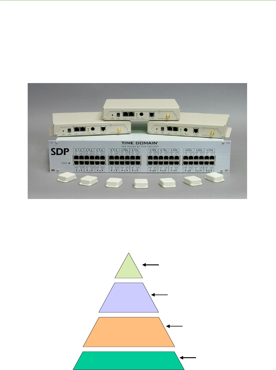
1. Overview
The Precision Location Ultra Wideband System (PLUS) is a state-of-the-art, real-time location
system (RTLS) utilizing ultra wideband technology. The PLUS RTLS provides unparalleled tag
capacity and precision location capability.
The contents of this manual are applicable to Release 2.0 of the PLUS hardware and software. Users
of Release 1.0 PLUS components should refer to the PLUS System Manual, document #P320-0191
for instructions applicable to the previous generation of hardware and software.
Figure 1-1 : PLUS SDP, Readers, and Tags
This System Manual is a comprehensive reference that serves a broad spectrum of PLUS users.
Figure 1-2 : PLUS Interfaces provides a high-level view of the various layers across which users may
wish to interface to the system.
P L U S L o c a t io n
S o f tw a r e
In s ta lla t io n
S o f tw a r e
P L U S R e a d e r
P L U S H a r d w a r e I n fra s tr u c tu r e
S e c tio n 4
P L U S L o c a tio n S o ft w a re L ib r a r y
H i g h L e v e l S y ste m I n te rfa ce / I n te r fa c e to
L o ca tio n S o ftw a re
S e c tio n 5
P L U S V i s u aliz er
V is u a liz er , I n s ta ll a tio n /M a in te n a n c e
S o ftw a r e T o o ls
S e c tio n 3
P L U S R e a d er D a ta I n te rf ac e
R e a d e r S o f tw a r e I n te rfa ce -
C o m m a n d s, R e sp o n s es , R a w T O A P a c k e t
D e f in it io n
S e c tio n 2
P L U S S y ste m In s ta lla tio n
R e a d e rs , T a g s , S D P , C a b lin g ,
P o w e r , H a rd w a r e
C o n f ig u r a tio n
P L U S L o c a t io n
S o f tw a r e
In s ta lla t io n
S o f tw a r e
P L U S R e a d e r
P L U S H a r d w a r e I n fra s tr u c tu r e
S e c tio n 4
P L U S L o c a tio n S o ft w a r e L i b r a r y
H i g h L e v e l S y ste m I n te rfa ce / I n te r fa c e to
L o ca tio n S o ftw a re
S e c tio n 4
P L U S L o c a tio n S o ft w a r e L i b r a r y
S e c tio n 4
P L U S L o c a tio n S o ft w a r e L i b r a r y
H i g h L e v e l S y ste m I n te rfa ce / I n te r fa c e to
L o ca tio n S o ftw a re
S e c tio n 5
P L U S V i s u aliz er
V is u a liz er , I n s ta ll a tio n /M a in te n a n c e
S o ftw a r e T o o ls
S e c tio n 5
P L U S V i s u aliz er
S e c tio n 5
P L U S V i s u aliz er
V is u a liz er , I n s ta ll a tio n /M a in te n a n c e
S o ftw a r e T o o ls
S e c tio n 3
P L U S R e a d e r D a ta I n te rf a c e
R e a d e r S o f tw a r e I n te rfa ce -
C o m m a n d s, R e sp o n s es , R a w T O A P a c k e t
D e f in i tio n
S e c tio n 3
P L U S R e a d e r D a ta I n te rf a c e
S e c tio n 3
P L U S R e a d e r D a ta I n te rf a c e
R e a d e r S o f tw a r e I n te rfa ce -
C o m m a n d s, R e sp o n s es , R a w T O A P a c k e t
D e f in i tio n
S e c tio n 2
P L U S S y ste m In s ta lla tio n
R e a d e rs , T a g s , S D P , C a b lin g ,
P o w e r , H a rd w a r e
C o n f ig u r a tio n
S e c tio n 2
P L U S S y ste m In s ta lla tio n
S e c tio n 2
P L U S S y ste m In s ta lla tio n
R e a d e rs , T a g s , S D P , C a b lin g ,
P o w e r , H a rd w a r e
C o n f ig u r a tio n
Figure 1-2 : PLUS Interfaces
PLUS System Manual Overview 11
Proprietary Information: Do not disclose unless authorized under a Nondisclosure Agreement and the Partner Agreement.
1.1 Manual Contents
The sections of this document are organized to allow system installers, programmers, and users to
easily find the information they need.
Section 1 provides an introduction to the PLUS system, with a summary of the PLUS products and
peripherals. All users should start with this introduction to familiarize themselves with the system.
Section 2 is the System Installation reference for the system. It contains a comprehensive set of
instructions for installing, configuring, and maintaining a PLUS system. The information in this
section will enable demonstration kit users to quickly set up their system. It also serves as a reference
for certified PLUS installers working on larger scale installations.
Section 3 describes the data interface to the PLUS Reader. It is intended for programmers who will
develop their own RFID or multilateration software using PLUS hardware components. The structure
of the Reader output data stream is documented in this section.
Section 4 describes the PLUS Location Software Library, which serves as the application interface
(API) for the system. This section enables middleware or application programmers to configure the
PLUS Location Engine and capture location data.
Section 5 is the reference manual for the PLUS Visualizer application. The Visualizer is a software
tool that enables users to set up, demonstrate, troubleshoot, and maintain a PLUS installation.
1.2 PLUS System Products
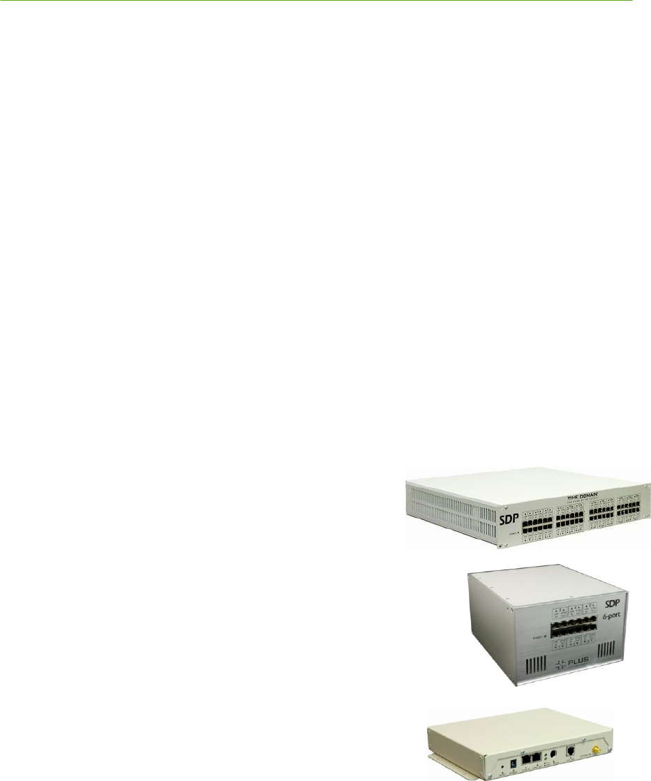
1.2.1 Synchronization Distribution Panel
A typical PLUS System includes at least one Synchronization
Distribution Panel (SDP) acting as a bridge between the
Location Engine server and the Reader units. The SDP serves
three functions in a tracking system: 1) Power delivery to
Readers (up to three per Sync Out port); 2) Synchronization of
Readers (up to six per Sync Out port); and 3) Pass-through of Ethernet
data within each paired set of LAN In and Sync Out ports. The SDP will
typically be connected to an Ethernet switch to aggregate data before
passing it to the Location Engine server. There are two versions of the
SDP: a 24-port version and a 6-port version.
1.2.2 Reader
The PLUS Reader performs the functions of receiving the PLUS
Tag transmissions, decoding Tag data, measuring signal strength,
and generating a Time of Arrival (TOA) timestamp. A typical
tracking system deployment consists of multiple Readers powered
from and synchronized to an SDP. It is also possible to use
individual Readers in RFID proximity detect mode. Each Reader
passes Tag data and TOA results to the Location Engine server through a 10/100 Mbps Ethernet link
using UDP/IP packets. The Reader interface also provides network configuration options, alert
conditions, and Reader diagnostics. Details on Reader configuration options and packet definitions
are provided in Section 3 PLUS Reader Data Interface of this manual.
12 Overview PLUS System Manual
Proprietary Information: Do not disclose unless authorized under a Nondisclosure Agreement and the Partner Agreement.
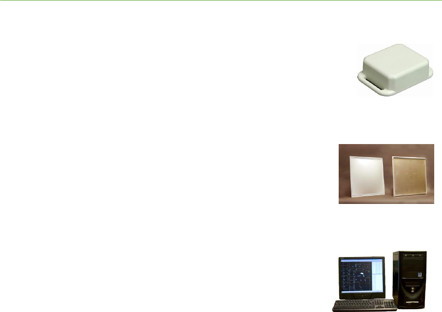
1.2.3 Asset Tag
The PLUS Tag is an ultra wideband active transmitter. Once per second, the
Tag transmits a short packet containing a unique serial number. One or more
PLUS Readers receive this transmission and pass the Tag data and Time of
Arrival (TOA) to a Location Engine which calculates the precise location of the
Tag. The PLUS Tag is small and durable, with a plastic housing that allows it to
be attached to assets or people. The Tag has a four-year battery life and requires no maintenance.
1.2.4 Antenna
The PLUS Antenna is available in 180 degree directional and
omnidirectional versions, and replaces a standard 2’x2’ ceiling tile in
suspended ceiling systems. The bottom of the Antenna is a white plastic
dome that allows it to blend in to the ceiling for an inconspicuous aesthetic
appearance. The Reader mounts to the top of the Antenna and is concealed
above the ceiling.
1.2.5 Location Software
The PLUS Location Software Library is a Windows-based software
component which is installed from the software CD included with the
PLUS software / documentation package. It is supported on Microsoft
Windows XP and Vista operating systems.
The library component is an OCX COM object library that provides
functions including buffering of Reader UDP packets, solving for the Tag location, and delivery of
location data to the developer’s application. The portion of the Location Engine that calculates tag
locations is also referred to as the Solver.
1.3 Additional Components and Peripherals
1.3.1 Visualizer
The PLUS Visualizer is a Windows-based application which is installed from the software CD
included with the PLUS software / documentation package.
The Visualizer component is a graphical software tool for use in system setup, diagnostics, and
demonstrations. It interfaces to the PLUS Readers through the PLUS Location Software Library
described above in Section 1.2.5 Location Software. After a PLUS system is in place and operating,
the Visualizer does not need to be run on a continuous basis – instead, it can be used as a maintenance
tool when changes are made to the system. Typically, third party graphical software will replace the
Visualizer as the system monitor in a customized system.
1.3.2 Location Software Server
A user-supplied server is needed to run the PLUS Location Software Library. Recommended
specifications for the Location Engine server to maximize Tag capacity are as follows.
Operating System Microsoft Windows XP or Windows Vista
CPU Intel Quad Core 2.4 GHz
Memory 3 GB RAM
NIC One 10/100/1000 Mbps card for RTLS network traffic

PLUS System Manual Overview 13
Proprietary Information: Do not disclose unless authorized under a Nondisclosure Agreement and the Partner Agreement.
One 10/100/1000 Mbps card for LAN connectivity
1.3.3 Ethernet Cable
The SDP and Reader components must be connected with 24-gauge CAT 5e shielded cable or
better. This grade of cable is required for readers to perform according to specifications. Avoid
breaking cable continuity by routing through breakout or junction blocks. If it is necessary to break
cable continuity, shield integrity should be maintained across the interconnect. Avoid using
connectors that rely on a crimp connection to maintain ground wire integrity; instead, use cables on
which the ground wire is soldered to the shielded connector.
1.3.4 PS/2 Serial Adapter Cable
If you wish to connect to a reader through its serial port to change IP addresses, you will need a PS/2
male cable connection to connect to the Reader. This is typically accomplished with a DB-9 to PS/2
serial adapter. One serial adapter cable is included in each PLUS software / documentation package.
TIP: Many PCs and laptops no longer come with DB-9 connectors, so you may also need a
USB to DB-9 adapter.
1.3.5 Reader Power Supplies
Readers that are run independently of an SDP, or Readers that are added onto a daisy chain and
exceed the SDP power delivery capacity, must be powered from an external 48V power supply.
Reader daisy chain configurations requiring external power are detailed later in this document.
Reader power supplies are available for purchase from Time Domain.
1.3.6 Ethernet Switch
A user-supplied Ethernet switch is needed to aggregate traffic from the Reader network and deliver it
to the Location Engine server. For full-scale PLUS deployments, the following specification are
recommended for the Ethernet switch connected to the SDP.
DRAM/flash memory 32MB DRAM 16MB flash memory
Switching capacity 8.8 Gbps
Forwarding rate 6.6-Mpps wire-speed
Switching Protocol Layer 2 Switching
Small-scale systems with low data bandwidths (only a few tags) can generally use any
consumer grade Ethernet switch or hub without impact.
14 System Installation PLUS System Manual
Proprietary Information: Do not disclose unless authorized under a Nondisclosure Agreement and the Partner Agreement.
2. PLUS System Installation
This section of the PLUS System Manual describes the setup and configuration steps that are required
for a PLUS installation. Most of the setup steps are the same for a small or large installation, but
large installations a degree of planning and testing that can be minimized in smaller installations.
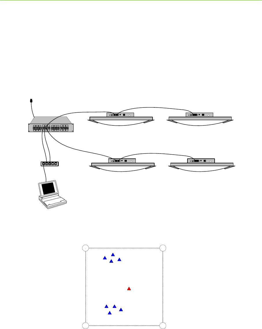
Development Kit Users: The information in this manual will enable first-time users to set up and
configure small-scale systems for evaluation and demonstration. Hardware connections and
placement for a small-scale system are shown in Figure 2-1: Hardware Connections for a Four-
Reader System and Figure 2-2: Hardware Placement for a Four-Reader System.
Please read through the entire installation process before beginning setup of your system.
AC Power Reader with
Antenna
SDP CAT 5e
PC
Hub or
Switch
CAT 5e
Reader with
Antenna
Reader with
Antenna CAT 5e
Reader with
Antenna
Figure 2-1: Hardware Connections for a Four-Reader System
Reader 1 Reader 2
Reader 3Reader 4
Tags
Tags
Calibration
Tag
Figure 2-2: Hardware Placement for a Four-Reader System
Certified Installers: This manual also serves as a reference for PLUS certified installers working on
larger installations. It complements the materials offered in PLUS certification training classes, but is
not intended to serve as a standalone training guide.

PLUS System Manual System Installation 15
Proprietary Information: Do not disclose unless authorized under a Nondisclosure Agreement and the Partner Agreement.
2.1 Pre-Installation Site Survey
Prior to installing a system, the installation site must be inspected and a plan developed to determine
the number and locations of hardware components that will be needed. There are several planning
steps and rules of thumb that should be applied when evaluating an installation site:
1) Obtain an accurate, electronic format building plan. The plan will be needed to estimate and
document intended Reader and Calibration Tag locations, develop a Reader placement and wiring
plan, develop a floor plan for the software application, and facilitate the coordinate survey after
hardware components have been installed.
All location information is ultimately compared to zones and locations defined by the
floorplan. The effort involved in generating an accurate floorplan is often underestimated
and can result in one of the largest sources of error in the system.
2) Identify areas on the building plan where accurate 2D location is most important. Reader density
and geometries should receive the most attention in these areas.
3) For the system to calculate a 2D Tag position, the Tag needs to be heard by at least three Readers.
In areas where the Tags will be moving or human activity may cause occasional blockage, plan
Reader locations such that at four or more Readers are within range of the Tags.
4) For normal stud and drywall construction, Readers will typically hear Tags at a distance of 45’
through one wall or 30’ through two walls. Identify and plan around building features that may
block the signal, such as metal pipes, ductwork, reinforced stairwells, foil-backed insulation,
elevators, etc. Wall construction consisting of additional layers of drywall, brick, concrete, and
cinderblock will cause higher signal loss and should receive extra attention.
5) Plan to use directional antennas when possible to maximize range for Readers on the periphery of
the installation.
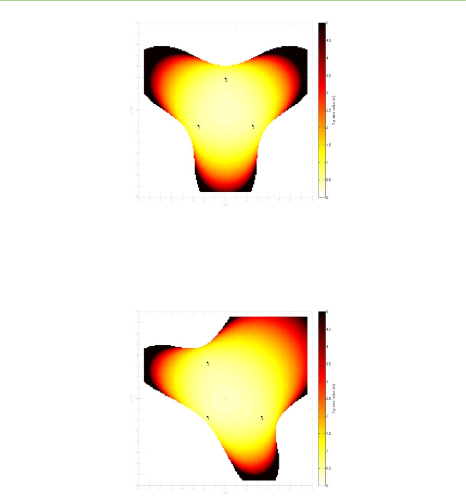
6) Be aware of Reader geometry limitations. Readers forming equilateral triangles are generally
best. In Figure 2-3, three readers are shown in an equilateral configuration. The lighter areas
represent best location precision, and darker areas represent lower accuracy regions. The system
will generally not be able to produce a solution in the white areas outside of the three-lobed
region.
16 System Installation PLUS System Manual
Proprietary Information: Do not disclose unless authorized under a Nondisclosure Agreement and the Partner Agreement.
Figure 2-3: Equilateral Triangle Reader Geometry
As shown in Figure 2-4, right triangles can also work well but will have a no-solution region
close to the right-angle vertex.
Figure 2-4: Right Triangle Reader Geometry
7) When selecting Reader mounting locations, be sure that the area is accessible and not blocked by
light fixtures, sprinkler heads, exit signs, etc. Select areas where Readers/Antenna assemblies can
be mounted at heights between 6’ and 15’. Note that PLUS Location Software 2.0 is able to
calculate 2D Tag positions using Readers mounted at different heights.
PLUS System Manual System Installation 17
Proprietary Information: Do not disclose unless authorized under a Nondisclosure Agreement and the Partner Agreement.
2.2 Reader Placement and Wiring Diagram
After identifying the locations where Readers will be installed, you should develop a diagram that
illustrates where Readers will be placed and how they will be connected to each other and to the SDP.
Use the building floor plan to mark Reader locations, label each wiring chain, and clearly identify
which Reader locations are at the beginning, middle, and end of each chain.
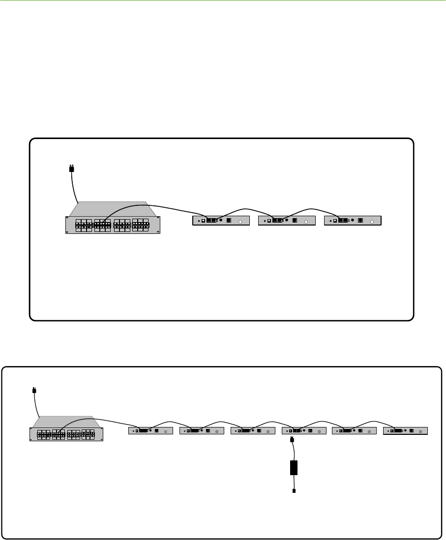
Wiring chains with more than three Readers require the use of an external Reader power supply. The
diagrams below describe your options for connecting and powering Readers.
AC Power
Reader 1
SDP Reader 2 Reader 3
No additional power supplies required for up
to three Readers per port
Figure 2-5: One through Three Readers per Chain
A C P o w e r
R e a d e r 1
S D P R e a d e r 2 R e a d e r 3 R e a d e r 4 R e a d e r 5 R e a d e r 6
48 V
S u p p ly
Figure 2-6: Four through Six Readers Per Chain
It is recommended that wiring be put into place prior to installation of the Readers and Antennas. Use
a qualified electrical contractor to ensure that building codes are followed. After wiring has been
completed, update the wiring diagram with any changes that were necessary. Use a visual cue (tape
marker, etc) on the ceiling so that the ends of the cables can be easily located behind the correct
ceiling tile.

18 System Installation PLUS System Manual
Proprietary Information: Do not disclose unless authorized under a Nondisclosure Agreement and the Partner Agreement.
2.3 Installation Overview
The next section of this manual covers the physical installation and checkout of the system. When
installing the PLUS hardware, the following steps should be followed to ensure correct system
operation. Use this list as a checklist to make sure that all the necessary configuration steps have
been followed. Each item on the checklist is described in detail below.
a) _______ Unpacking and inspecting hardware
b) _______ Installing and powering the SDP
c) _______ Configuring Reader and solver IP address
d) _______ Ceiling installation of Readers and Antennas
e) _______ Surveying Readers and generating coordinates
f) _______ Connecting the SDP, Ethernet switch, and server
g) _______ Server IP address configuration
h) _______ Server firewall settings
i) _______ PLUS Visualizer software installation
j) _______ Setting data input
k) _______ Checking Reader communications
l) _______ Reader configuration – defining groups and maps
m) _______ Entering floor plan data
n) _______ Calibration Tag placement
o) _______ Calibration Tag configuration
p) _______ Calibrating the system
q) _______ Verifying system performance
2.3.1 Unpacking and Inspecting Hardware
Unpack the PLUS Readers, Antennas, SDP, and Tags, and make sure that no damage has occurred
during shipping. Verify that all mounting hardware and peripheral components are on hand.
2.3.2 Installing and Powering the SDP
Place the SDP in its intended operating location and apply AC power. Also, set up the Ethernet
switch that will service the tracking network at this time. By setting up the SDP first, you can power
up and check the operation of each Reader as it is installed.
Plug each PLUS network cable into a ―SYNC OUT‖ port of the SDP. Be sure that the RJ-45
connector snaps into the receptacle firmly. If the RJ-45 connector will not snap firmly into the
receptacle, do not use this cable, as a reliable connection cannot be guaranteed.
Tip: If you are installing a 24-port SDP, use a 19” equipment rack when possible. You will
be able to connect cables more easily and ensure reliable connections if the SDP is mounted
in a rack.

PLUS System Manual System Installation 19
Proprietary Information: Do not disclose unless authorized under a Nondisclosure Agreement and the Partner Agreement.
2.3.3 Configuring Reader and Location Engine IP Addresses
Reader Static IP and Dynamic IP Addresses
By default, Readers are configured to request an IP address from a DHCP server each time they are
booted. If you plan to use dynamic IP assignment, the server connected to your tracking
network must host a DHCP server. If you do not have access to, or are unfamiliar with setup of a
DHCP server, it is recommended that you use a serial connection to configure each Reader with a
static IP address using the changeIp command (example below).
Configuring a Reader for the Location Engine IP Address
Each Reader must be configured with the IP address of the Location Engine to which it sends data.
The Location Engine IP address is the IP address of the Network Interface Card (NIC) in the server
that will host the PLUS Location Software Library. The Location Engine IP address is specified by
connecting to the Reader with a serial connection and running the solverIp command (example
below).
Reader and Location Engine IP Address Configuration Procedure
Changing a Reader from dynamic addressing to a static IP and specifying the Location Engine IP
address requires using terminal software (HyperTerminal or similar) to connect to the Reader through
its serial port. The supplied serial port adapter (DB9 to PS/2) is needed to connect to the serial port
on the front panel of the Reader.
1) Power the Reader by connecting a 48V supply to the Reader DC input, or connect a Sync Out
port of an active SDP to the Reader Sync In port
2) Connect the serial port adapter to the serial port on the front panel of the Reader
3) Connect a serial cable from your server to the serial port adapter
4) Configure your terminal software for 115,200 baud, 8 data bits, no parity, 1 stop bit, and no flow
control
5) Connect to the Reader and login with user name p350 and password timedomain (case sensitive)
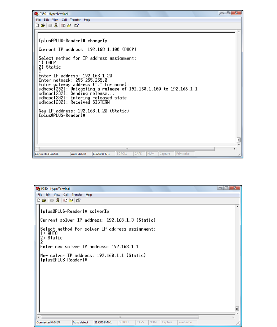
6) Type "changeIp" to run the IP configuration utility
7) Select option 2 to enter the static IP address
8) Enter the subnet mask (typically 255.255.255.0)
9) Enter "." for no gateway address
10) The Reader will report the new IP address – confirm that the value is correct
11) Exit the IP configuration utility
12) Type ―solverIp‖ to run the Location Engine address configuration utility
13) Enter the IP address of the NIC card of the server hosting the Visualizer (see Section 2.3.6.2
Server IP Address Configuration below).
14) The Reader will report the new solver IP address – confirm that the value is correct
15) Close the serial connection and disconnect the port
20 System Installation PLUS System Manual
Proprietary Information: Do not disclose unless authorized under a Nondisclosure Agreement and the Partner Agreement.
Figure 2-7: Reader IP Address Configuration
Figure 2-8: Solver IP Address Configuration
PLUS System Manual System Installation 21
Proprietary Information: Do not disclose unless authorized under a Nondisclosure Agreement and the Partner Agreement.
2.3.4 Ceiling Installation of Readers and Antennas
The following steps describe how to connect a Reader to an Antenna and install the assembly into the
ceiling. Start by installing the first Reader in the chain from the SDP, and proceed down the chain to
the last Reader. This will allow Readers to be powered and their operation verified as they are installed.
2.3.4.1 Mounting Readers to Antennas
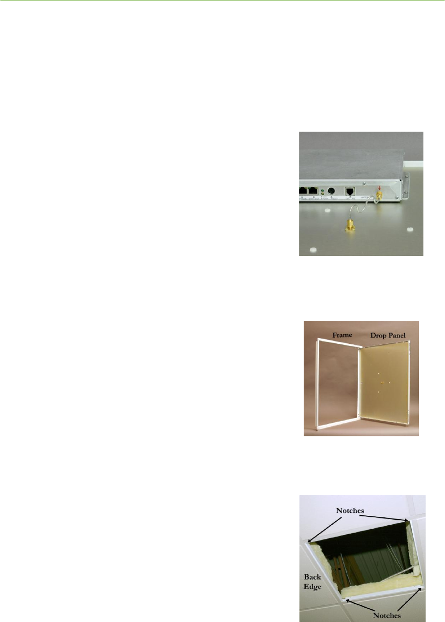
1) Place the Antenna panel dome-side down on a flat surface, and place the Reader on the Antenna
panel. Align the four screw slots in the reader flanges with the
holes in the Antenna panel.
2) Connect the Reader SMA port to the Antenna SMA port using
the provided coaxial cable. Hand-tighten the SMA
connections.
3) Screw the reader to the Antenna panel using the screws
provided in the Antenna kit.
4) Tighten the SMA connectors to 3-5 in-lbs using a 5/16"
wrench. Do not over-tighten the SMA connectors.
Figure 2-9: Reader Connection
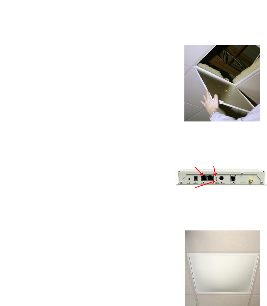
2.3.4.2 Installing Reader / Hinged Antenna
Assemblies
1. Remove the existing ceiling tile and any insulation batts above
the tile. Do not re-install insulation after the Antenna is
mounted.
2. NOTE: If a 2' x 4' tile is being replaced, a cross tie (not
included) may be added for improved cosmetic appearance
for the ceiling tile; the PLUS antenna is rigid enough that it
does not need a cross tie for support.
Figure 2-10: Antenna Frame
and Drop Panel
3. Prior to inserting the Antenna frame into the ceiling, rotate the
frame so that the notches at the corners of the frame are
oriented to the left and right rear sides of the frame.
4. Tilt the Antenna frame and insert it into the ceiling opening.
Lower the frame so that it is seated evenly on the drop ceiling
cross-ties.
Figure 2-11: Frame
Orientation
22 System Installation PLUS System Manual
Proprietary Information: Do not disclose unless authorized under a Nondisclosure Agreement and the Partner Agreement.
5. Tilt the drop panel and insert it into the frame opening. Lower
the panel so that it is seated evenly on the Antenna frame.
6. Connect the proper Ethernet cable to SYNC IN port of the
Reader. Verify that the cable snaps into the connector firmly and
the Reader powers on (via Ethernet LEDs). If there are
additional Readers in the chain, connect the proper Ethernet cable
to the SYNC OUT port of the Reader.
Figure 2-12: Drop Panel
Installation (shown with
no Reader mounted)
7. Verify that the Reader has booted (via the POWER LED on
steady) and is able to receive Tag traffic, as indicated by a
blinking DATA light.
Reader LED Indicators
8. Close the drop panel and slide the latches into the locked
(outward) position.
Figure 2-13: Closed Panel
1) Ethernet
LEDs Blink 3) Tag Traffic
2) Power LED on
steady (after several
seconds)
PLUS System Manual System Installation 23
Proprietary Information: Do not disclose unless authorized under a Nondisclosure Agreement and the Partner Agreement.
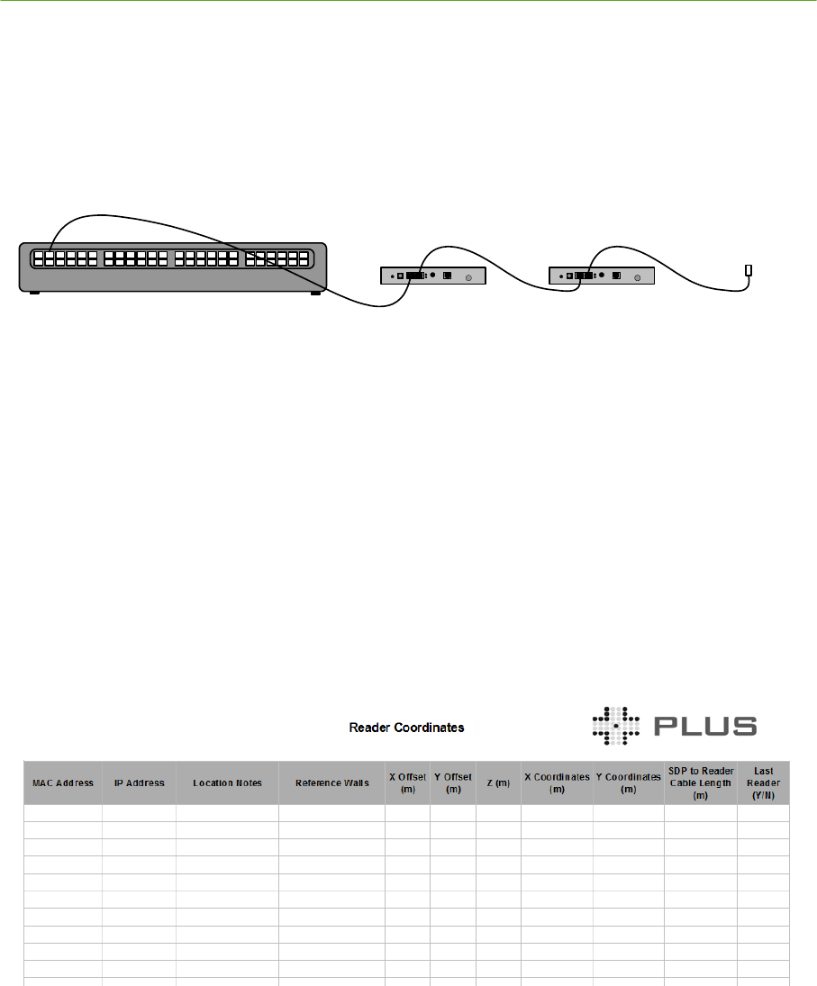
IMPORTANT:
Do not attempt to use the system with an unterminated Ethernet cable plugged into the SYNC
OUT port of a Reader, or unstable operation can result. An Ethernet cable plugged into the
SYNC OUT port of a Reader must be plugged into the SYNC IN port of another Reader to be
properly terminated.
Reader Reader
S D P
U n te rm in a te d
C a b le
Figure 2-14: Unterminated Ethernet Cables
2.3.5 Surveying Readers and Generating Coordinates
After Readers have been installed in the ceiling, their locations can be surveyed and coordinates
generated for entry into the Visualizer software. There are many approaches to surveying locations,
and specific measurement techniques are beyond the scope of this document. The result of the survey
process will be Reader locations in a 3D rectangular coordinate system established relative to the
building floor plan. It is important to perform an accurate survey to enable the best results from the
Location Engine. The goal should be inch-level accuracy for the Reader survey. The origin of the
coordinate system may be a Reader location, corner of the building, or some other architectural
reference point that is easy to reference. Maintain this information in a spreadsheet (Figure 2-15)
including Reader MAC address and X-Y-Z location. Reader and Calibration Tag installation
worksheets are included at the end of this section.
Figure 2-15: PLUS Reader Installation Worksheet
24 System Installation PLUS System Manual
Proprietary Information: Do not disclose unless authorized under a Nondisclosure Agreement and the Partner Agreement.
2.3.6 Server Setup and Software Installation
The following steps describe the process of connecting to a server through an Ethernet switch,
configuring server network settings, and installing the PLUS software.
2.3.6.1 Connecting the SDP, Ethernet Switch, and Server
The Ethernet traffic on each SDP ―LAN IN‖ port is isolated from all other ―LAN IN‖ ports and must
be routed through an Ethernet switch to the server. Very small installations may be able to use an
Ethernet hub to connect to the network, but larger installations should use an Ethernet switch that
meets the minimum specifications to avoid data loss.
For each SDP ―SYNC OUT‖ port that is connected to a Reader chain, connect the corresponding
―LAN IN‖ port to the Ethernet switch. Standard CAT 5 cable may be used. Be sure that the cable
snaps firmly into place.
Connect one port on the Ethernet switch to the server NIC that will be handling tracking network
data.
Loose cable connections at the SDP can be costly in terms of time spent troubleshooting. If a
cable will not plug securely into the SDP, correct the problem before continuing with the
installation.
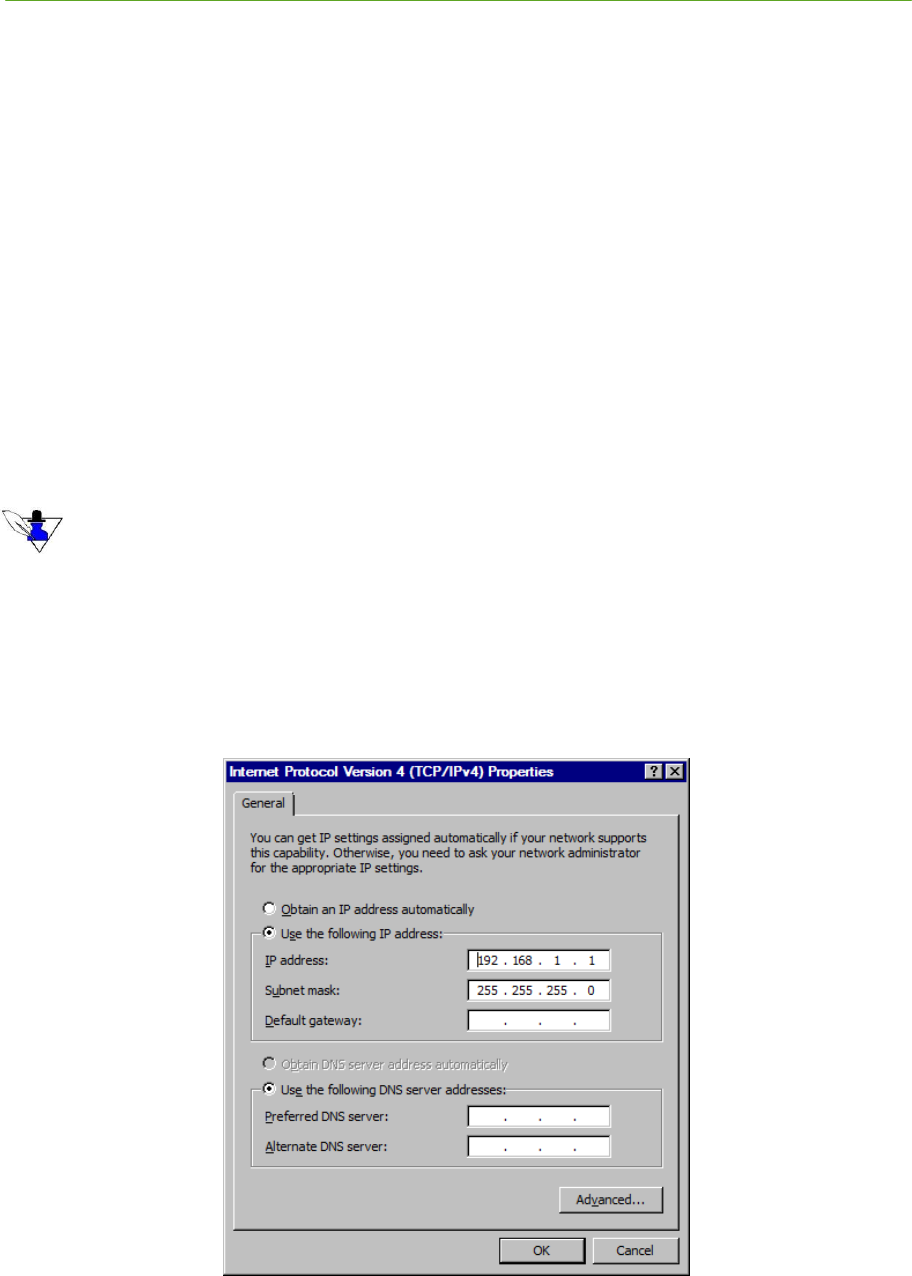
2.3.6.2 Server IP Address Configuration
The server that will be used to run the PLUS Software should be equipped with a NIC card dedicated
to the tracking network. Set the IP address to match the Location Engine address configured on the
Readers. The example below demonstrates configuration of a NIC card with IP address 10.1.4.1 and
subnet mask of 255.255.255.0.
Figure 2-16: TCP/IP Properties

PLUS System Manual System Installation 25
Proprietary Information: Do not disclose unless authorized under a Nondisclosure Agreement and the Partner Agreement.
2.3.6.3 Server Firewall Settings
If the server on which you will be running the Visualizer has a firewall enabled, be sure that the
firewall settings will allow traffic from the subnet assigned to the Readers. For convenience, you
may wish to temporarily disable the firewall until you have verified that you are receiving traffic from
the Readers correctly.
26 System Installation PLUS System Manual
Proprietary Information: Do not disclose unless authorized under a Nondisclosure Agreement and the Partner Agreement.
2.4 Configuring the System Using Visualizer
This section describes how to use the Visualizer application to configure the data source for the
Visualizer, check for reliable Reader communications, enter Reader, Group and Map configuration
data into the system, and enter a floor plan.
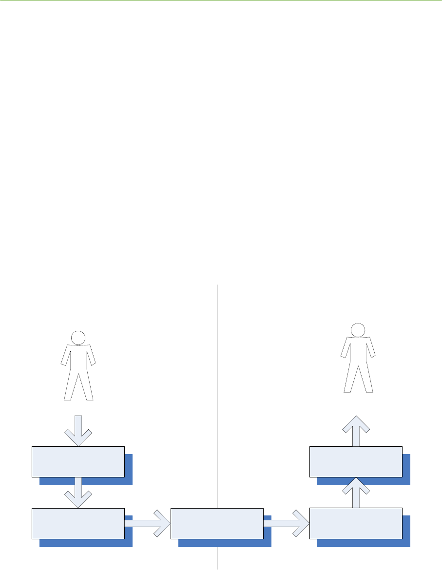
2.4.1 Workflow
Visualizer is the recommended tool for configuring a new PLUS installation, making changes to an
existing installation, or troubleshooting an installation. Visualizer provides a graphical interface to set
up and calibrate Readers and verify operation of the system. When the user makes changes with
Visualizer, the Visualizer uses the Location Engine API to change the Location Engine configuration.
Saving a configuration causes the Location Engine to generate a trackerconfig.txt file in the
configuration directory.
When the Visualizer or other user application is run, the Location Engine uses the data in the
configuration file for initialization. This allows most of the complexity of setting up a system to be
managed by Visualizer and the installer who is configuring the system. The result is that the user
application does not need to implement the full set of configuration features of the API, and can
instead rely on initializing the Location Engine by pointing to the existing configuration file.
V is u a liz e r
Location
E n g in e
C o n fig u ra tio n
F ile
U s e r
A p p lic a tio n
Location
E n g in e
S y s te m In s ta lla tio n S y s te m O p e r a tio n
U s e r
In s ta lle r
Figure 2-17: PLUS Configuration Workflow
PLUS System Manual System Installation 27
Proprietary Information: Do not disclose unless authorized under a Nondisclosure Agreement and the Partner Agreement.
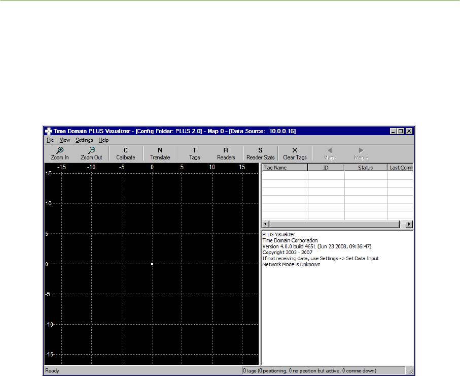
2.4.2 PLUS Visualizer Software Installation
Insert the PLUS Visualizer Setup CD and follow the InstallShield Wizard instructions. If you are
updating a previous installation, use the ―Upgrade‖ option. After installation is complete, run the
PLUS Visualizer application.
Figure 2-18: Visualizer Application
28 System Installation PLUS System Manual
Proprietary Information: Do not disclose unless authorized under a Nondisclosure Agreement and the Partner Agreement.
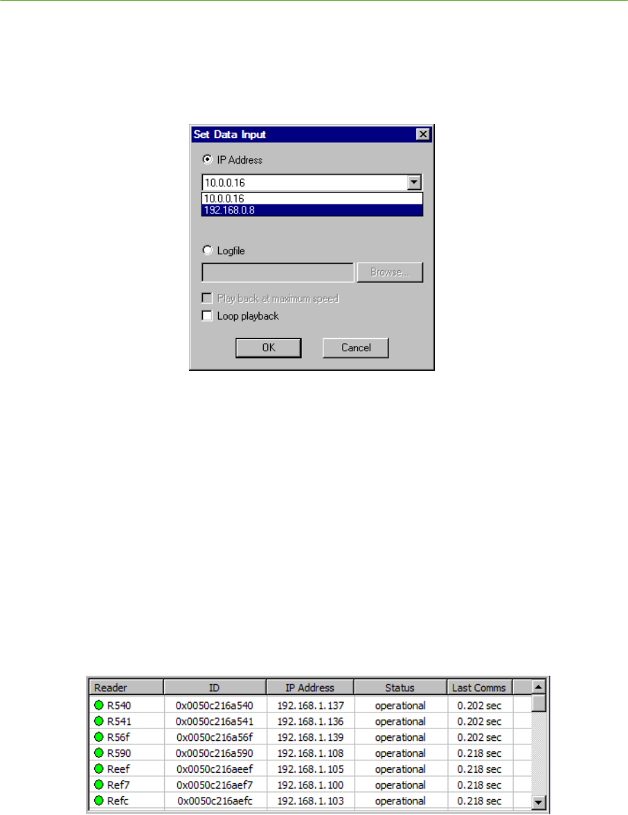
2.4.3 Set Data Input
Under the Settings menu, open the Set Data Input… selection. Select the IP Address radio button.
Pull down the list box to select the IP address for the NIC that is receiving tracking network data and
click the OK button (See Figure 2-19: Set Data Input). The Message Frame will update with a list of
Readers and Tags that are added to the system.
Figure 2-19: Set Data Input
2.4.4 Check Reader Communications
In the Visualizer tool bar, click the Readers button. The List View frame shows the list of Readers
that are active and/or have been added as offline Readers. Check the list of Readers to verify that it is
showing all Readers in the system.
The Last Comms column of the List View frame shows the amount of time that has passed since the
Reader last communicated with the location server. If the Reader does not hear a Tag for 10 seconds,
the Reader will send a discovery packet to the location server. This allows the Reader to be identified
even in the absence of Tags. When the location server receives either a Tag transmission or a discovery
packet from a Reader, the Last Comms count will reset. Verify that the Last Comms value for all
active Readers is 10 seconds or less. If any active Reader shows a Last Comms of greater than 10
seconds, the Reader and network path should be checked for errors. See the troubleshooting
information at the end of this section for more information.
Figure 2-20: Reader Communications
PLUS System Manual System Installation 29
Proprietary Information: Do not disclose unless authorized under a Nondisclosure Agreement and the Partner Agreement.
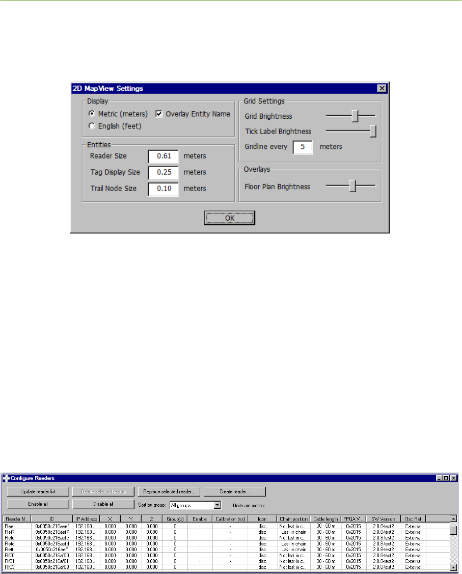
2.4.5 Setting English/Metric Units
Under the Settings menu, select 2D MapView Settings…. In the MapView Settings window, select
English or Metric according to which units you will use to enter Reader and Tag survey data.
Figure 2-21: Setting English/Metric Units
You may change other MapView settings to make the Visualizer easier to view during installation.
Check the Overlay Entity Name selection to show text identification next to Reader and Tag
icons on the map.
Set the Reader Size to 2.0’ and Tag Display Size to 0.3’, or other values as desired.
Set Grid Brightness as desired for your monitor
Set Gridlines every 5’, or as desired
2.4.6 Entering Reader Survey Data
Under the Settings menu, open the Reader Configuration window. You may enter survey data with
the Location Engine connected to a live system, or offline. Entering data with a live system has the
advantage of automatically populating the Reader Configuration screen with any Readers seen by the
Location Engine.
Figure 2-22: Reader Configuration Window
The Reader Configuration window will report either ―Units are feet‖ or ―Units are Meters‖. Check
that this is consistent with the survey data you are entering. Enter the X, Y, and Z coordinates for
each Reader. As you enter the survey data, the icons showing Reader locations will appear in the
MapView display. Check that all Readers appear in the correct location.

30 System Installation PLUS System Manual
Proprietary Information: Do not disclose unless authorized under a Nondisclosure Agreement and the Partner Agreement.
2.4.7 Reader Groups
2.4.7.1 Reader Groups Overview
The ability to create Reader Groups is an important feature of the 2.0 Location Engine. Establishing
multiple Reader Groups allows a large installation to be divided into small sections, each of which
acts as an independent location system. Managing a PLUS system as a set of small, independent
systems is much easier than trying to work with one large group of Readers. By creating independent
groups of Readers, the user can install Readers that operate off of different SDPs, are located on
different floors of a building, or are located in geographically separated areas.
2.4.7.2 Solution Types
When a group of Readers is created, you can set properties that control the type of location solution
that the group can produce. Groups may generate 0D, 1D, and 2D solutions.
0D Solutions, also called presence detect or proximity solutions, determine which Reader is closest to
the Tag and report the X,Y coordinates of this Reader as the Tag location. This type of solution is
useful when the general area of the Tag is needed. Reliable 0D solutions can be produced with a
sparse density of Readers.
1D Solutions are produced by assuming that the Tag solution will lie on a line between two Readers.
1D Reader groups are generally created with Readers in a hallway, when the tag is unlikely to enter or
be detected in rooms alongside the hallway. When setting up 1D groups, the participating Readers
should be at approximately the same height.
2D Solutions can be calculated when at least three Readers with good geometry are able to receive a
Tag. The X, Y, and Z coordinate of the Tag are reported, where the height (Z coordinate) is an input
to the system. When setting up 2D groups, the participating Readers may be at varying heights.
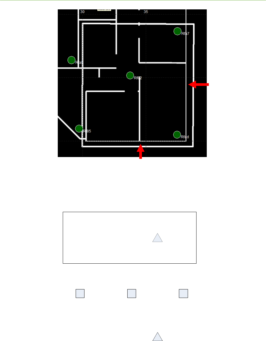
2.4.7.3 Tracking Cells
A tracking cell is a geometric region that acts as a filter for Tag locations. One tracking cell can be
defined for each Reader group and each map. You are not required to define tracking cells – if no cell
is defined, all valid outputs of the Location Engine will be used. Tag solutions that are inside the
tracking cell are considered valid. Tag solutions outside the tracking cell are either discarded, or are
snapped to the boundary of the tracking cell, depending on the parameters that the user has set.
Readers may be located inside or outside the boundaries of tracking cells – the cell operates based on
Tag positions, not the Readers used to generate those positions.
PLUS System Manual System Installation 31
Proprietary Information: Do not disclose unless authorized under a Nondisclosure Agreement and the Partner Agreement.
Figure 2-23: Tracking Cell for a Four-Reader Group
When tracking cells are defined for both a group and a map,
Tag solutions are tested against the group tracking cells first
If the solution passes the group tracking cell, it is then tested against the map tracking cell
Group tracking cells that share a border with map tracking cell should be defined with extra
margin outside of the boundary. This allows Tag positions with small amounts of error to pass the
group tracking cell criteria, and then be snapped to the edge of the map tracking cell boundary.
32 System Installation PLUS System Manual
Proprietary Information: Do not disclose unless authorized under a Nondisclosure Agreement and the Partner Agreement.
Figure 2-24: Group Tracking Cell with Boundary Margin
With some Reader geometries (such as Readers in a line), when the Location Engine attempts to
calculate a Tag position, it produces two results. Only one result represents the actual position. The
other result is a mirror-image, or ambiguous solution. By defining a tracking cell in these cases, the
Location Engine can filter the false solution.
R e a d e r 1 R e a d e r 2 R e a d e r 3
A c tu a l
T a g
P o s itio n
F a ls e ( M irr o r
Im a g e ) T a g
P o s itio n
T ra c k in g C e ll
Figure 2-25: Tracking Cell Used to Filter Ambiguous Solutions

PLUS System Manual System Installation 33
Proprietary Information: Do not disclose unless authorized under a Nondisclosure Agreement and the Partner Agreement.
2.4.7.4 Maps
Each Reader group is associated with a map. Multiple groups may be assigned to the same map, but a
group can be assigned to only a single map. All of the Readers on a given map have a common
coordinate system and origin. When a new group is created, it is assigned to Map 0 by default.
Visualizer allows you to import and scale a floorplan image file for each map. The process of
importing image files and setting other map properties is described in Map Configuration below.
2.4.7.5 Group Setup Guidelines
Below are some rules and guidelines for organizing Readers into groups.
Tip: Users of a PLUS demonstration kit with three or four Readers will generally not need
to assign Reader groups. Just leave Readers in the default Group 0 and proceed with
calibration.
Readers must belong to at least one group. When a new Reader enters the system, it is
automatically assigned to Group 0. If you delete an active Reader from the configuration, it will
be re-assigned to Group 0 the next time data from it is received.
New Readers that enter the system will be flagged as disabled by default.
Readers may be assigned to multiple groups. This allows for overlapping 2D location coverage
between adjacent groups of Readers.
The survey data for a Reader is unique for that Reader. If a Reader is a member of multiple
groups, its survey data will be the same in every group.
The calibration data for a Reader is a function of each group that the Reader belongs to. For
example, the Reader will be assigned one calibration value for Group 0, a different calibration
value for Group 1, and so on. This allows groups of Readers to be calibrated independently.
Each Reader has an Enable setting that is a function of each group that the Reader belongs to. A
Reader must be enabled in a given group to contribute to the locating algorithm for that group. A
Reader that is enabled in all groups it belongs to will have a green icon on the map display. A
Reader that is disabled for one or more groups will have a yellow icon on the map display.
All Readers in a group must be calibrated with respect to one another. More information on
calibration is provided in the System Calibration section.
To make management of groups easier, keep the number of Readers in a group to no more than
12 or 15.
To provide 2D Tag location, a group must have at least three Readers.
In most cases, you should not enable a group for both 1D and 2D tracking at the same time.
Doing so may result in a Tag location that ―jumps‖ if it transitions between a 1D and 2D solution.
When setting up a 1D Reader group, the Readers should be at approximately the same height.
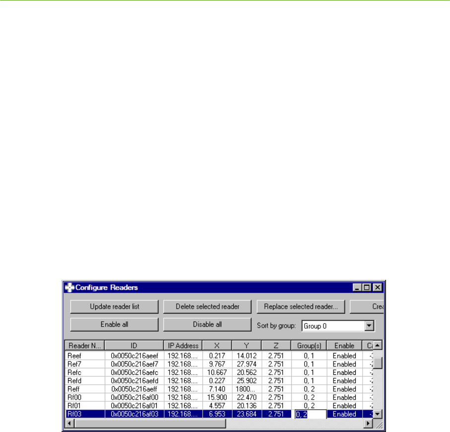
34 System Installation PLUS System Manual
Proprietary Information: Do not disclose unless authorized under a Nondisclosure Agreement and the Partner Agreement.
The tracking cell snap feature is primarily intended for use with Map tracking cells. Using a snap
setting with group tracking cells may result in undesired snap behavior in the interior of a
building.
Use architectural features of a building to break the system into meaningful groups. Hallways and
intersections make good boundaries between groups.
Use Group 0 as a ―stockpile‖ of unassigned Readers. Disable tracking for Group 0 (See ―Group
Properties‖ below), and instead use Groups 1, 2, etc. as your active groups.
You may find it helpful to display one or more Maps before making Reader group assignments.
See Map Properties below.
2.4.8 Assigning Reader Groups
There are two ways of assigning Reader groups in Visualizer.
1) From the Reader Configuration screen, under the Groups column, type in a comma-separated list
of group numbers for each Reader. If the group does not yet exist, you will be asked if you wish
to create the group.
Figure 2-26: Assigning Reader Groups
2) Open the Group Configuration window from the Settings Menu, and double click on a Reader in
the 2D MapView. This will highlight the Reader in the Member Reader list of the Group
Configuration window. Click the direction arrows to add or remove the Reader from the selected
group.
2.4.9 Group Properties
The Group Configuration window (Settings menu) allows you to set properties of each group. When
setting up the group configuration, you may wish to check the ―Display only this group in the
tracking view‖ box to remove other Readers from the 2D MapView.
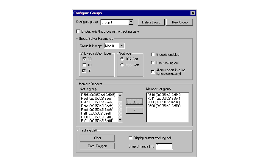
PLUS System Manual System Installation 35
Proprietary Information: Do not disclose unless authorized under a Nondisclosure Agreement and the Partner Agreement.
Figure 2-27: Group Configuration Window
Under the Group/Solver Parameters frame:
Check the 0D, 1D, and 2D boxes to select the type of location data this group will provide. 0D
and 2D are selected by default for a newly created group.
Sort type should be set to TOA Sort. There is one exception – a non-calibrated group of Readers
configured for 0D only should use RSSI Sort instead.
Check the ―Group is enabled‖ box to enable tracking with this group.
Check the ―Use tracking cell‖ box if you have defined a tracking cell for the group.
Check the ―Allow readers in a line‖ box if you want the system to solve with Readers in a
straight line. This may include two or more Readers for a 1D group, or three or more Readers
with a 2D group. Note that if you set up Readers in a line with a 2D group, you must also define a
tracking cell to remove ambiguous solutions.
The Member Readers frame is used to add or remove Readers from the group. Click on a Reader to
highlight it, then use the direction arrows to add or remove it as a member of the group.
Under the Tracking Cell frame:
To define a tracking cell for the group, click the Enter Polygon button in the Tracking Cell
frame. Click on the map display to place vertices of the polygon. As each vertex is placed, the
polygon will automatically draw a line to the original vertex to close the area. When finished,
click the Exit Polygon Mode button. The tracking cell will disappear at this point, unless the
“Display current tracking cell” box is checked.
Click the Clear button to remove the Group tracking cell.
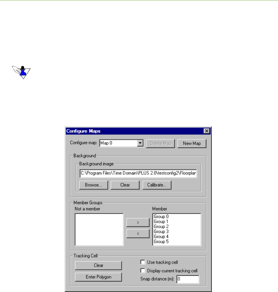
36 System Installation PLUS System Manual
Proprietary Information: Do not disclose unless authorized under a Nondisclosure Agreement and the Partner Agreement.
Click the Display current tracking cell box to show the Group tracking cell on the 2D
MapView.
You may enter a snap distance for the group tracking cell. If a snap distance is defined, Tags that
are located outside the tracking cell but less than the snap distance from the tracking cell will be
shown on the boundary of the tracking cell. If tag solutions are outside of the snap distance, they
will be discarded.
Snap distances are intended primarily for Map tracking cells. Using a snap distance
with Group tracking cells can result in location error along boundaries between groups.
2.4.10 Map Properties
The Map Configuration window (Settings menu) allows you to select an image file floorplan for the
map, scale the floorplan, assign groups to the map, and define a tracking cell for the map.
Figure 2-28: Map Configuration Window
Under the Background Image frame:
Browse for an image file to associate with the map. Supported image formats are bitmap, JPEG,
PNG, TIFF, and GIF.
The Calibrate Background Image window will open. You may calibrate the size of the floorplan
by entering the dimensions of the entire image file (under the Scaling frame), or clicking the
Calibrate line button and drawing a line of known dimensions on the image file.
Click the Clear button to remove the image file.
Click the Calibrate button to re-enter the calibration settings for the map.
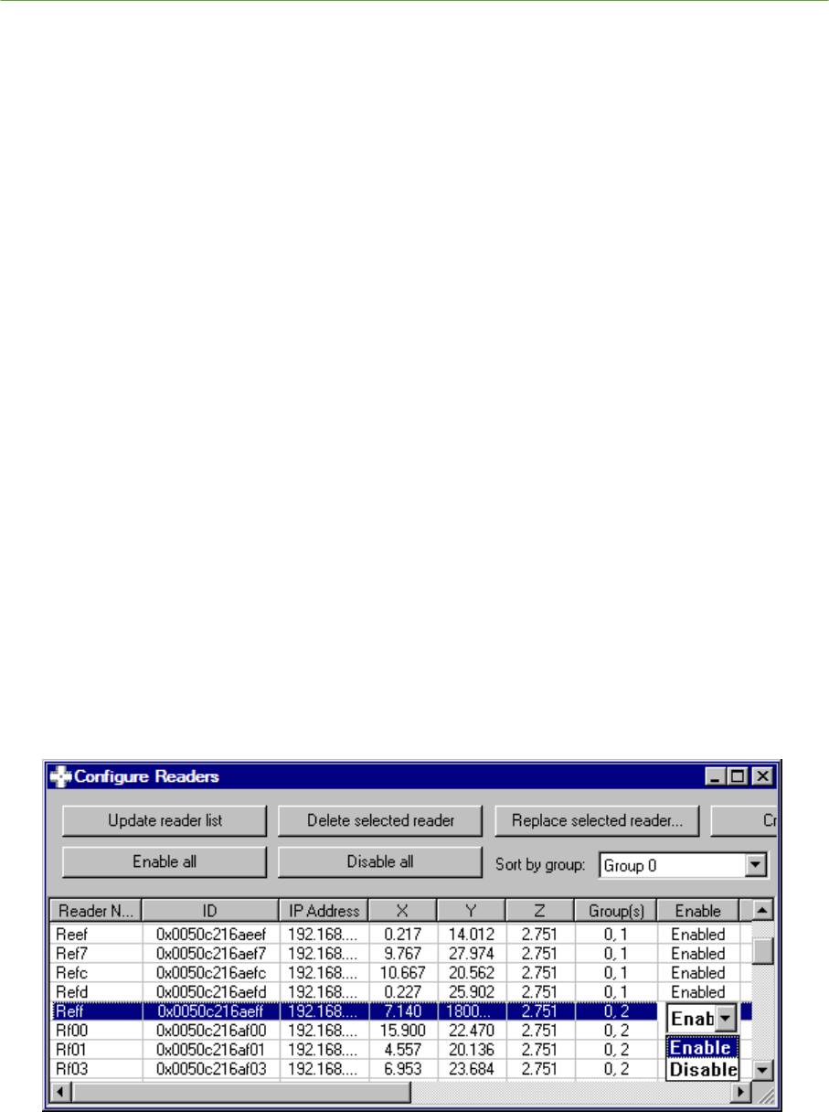
PLUS System Manual System Installation 37
Proprietary Information: Do not disclose unless authorized under a Nondisclosure Agreement and the Partner Agreement.
Under the Member Groups frame, click on a Reader group and use the direction arrows to add or
remove it from the selected map.
Under the Tracking Cell frame:
To define a tracking cell for the map, click the Enter Polygon button in the Tracking Cell frame.
Click on the map display to place vertices of the polygon. As each vertex is placed, the polygon
will automatically draw a line to the original vertex to close the area. When finished, click the
Exit Polygon Mode button.
Click Use tracking cell to make the Map tracking cell active.
Click the Clear button to remove the Map tracking cell.
Click the Display current tracking cell box to show the Map tracking cell in the 2D MapView.
You may enter a snap distance for the Map tracking cell. If a snap distance is defined, Tags with
solutions outside the tracking cell but less than the snap distance from the tracking cell will be
shown on the boundary of the tracking cell. If tag solutions are outside of the snap distance, they
will be discarded.
2.4.11 Enabling Readers
When you assign a Reader to a group, the Reader will be enabled for that group by default. The only
reason a Reader should be disabled in a group is for troubleshooting. For example if the Reader is
failing to calibrate, or appears to be causing a bad location result, it may be helpful to disable it until
the problem is corrected.
You can quickly enable or disable a Reader across all groups by using the ―Enable All‖ and ―Disable
All‖ buttons at the top of the Reader Configuration window. You can also enable or disable a Reader
on a per-group basis by first selecting a Group number in the Sort by Group field, and then toggling
the selection under the Enable Column.
Figure 2-29: Enabling and Disabling Readers in Group 0

38 System Installation PLUS System Manual
Proprietary Information: Do not disclose unless authorized under a Nondisclosure Agreement and the Partner Agreement.
2.4.12 Cable Length and Termination Settings
With the 2.0 Reader, cable length and termination settings are automatic, and these columns are for
user information only.
2.4.13 System Configuration Files
Under the File menu, select Save Config As… to create a new configuration folder. A PLUS
configuration consists of two files. Trackerconfig.txt is used by the Location Engine to store survey
information, calibration data and other system parameters. Visualizerconfig.txt stores map image file
parameters and tag name assignments. Do not edit these files manually; instead use Visualizer to
make changes to the configuration. Opening and saving a configuration from Visualizer is done by
referencing the folder containing the two configuration files rather than specifying the files
themselves.
The 2.0 Location Engine can read earlier versions of the configuration file. Simply rename the
configuration file to trackerconfig.txt, and use Visualizer to open the directory containing this file.

PLUS System Manual System Installation 39
Proprietary Information: Do not disclose unless authorized under a Nondisclosure Agreement and the Partner Agreement.
2.5 System Calibration
The following section describes the process of calibrating the PLUS system. The purpose of
calibration is to remove the time delays introduced by the varying length cables run to each Reader.
Because the Location Engine calculations are based on the Tag signal time of arrival to each Reader,
it is necessary to remove these additional timing delays to produce accurate location results.
With the 2.0 SDP and Readers, it is only necessary to calibrate the system one time as long
as no changes are made to the installation.
Do run a new calibration if Readers are added or replaced, or if cables are replaced.
Do not run a new calibration if the Readers or SDP are power cycled. The system will retain its
calibration through a power outage.
With the introduction of Reader groups in release 2.0 of the Location Engine, you can calibrate
groups all at once, or one at a time. This enables you to calibrate and verify the system by working
with a few Readers at a time. Two scenarios to illustrate calibration options are described below. In
each scenario, we will assume the same building layout and an installation consisting of fifty Readers.
Scenario 1: The fifty Readers are treated as a single group. Twenty tags are designated as calibration
tags, and are surveyed and permanently mounted in the facility. If a cable is replaced, it is necessary
to recalibrate all fifty Readers. Once a calibration has been configured (as explained in the following
paragraphs), it is easy to recalibrate using permanently mounted tags . The user must take care that
the environment does not change (people and equipment do not introduce blockage between the
calibration tags and readers) or errors could be introduced into the calibration.
Scenario 2: The fifty Readers are partitioned into five groups, averaging ten Readers each. Two
calibration tags are used to calibrate the system by surveying temporary locations and calibrating the
system one group at a time. If a cable is replaced, it is only necessary to recalibrate the groups
containing the affected Readers. The other groups can continue operating normally and generating
locations without disruption. Recalibrating the affected groups requires replacing the calibration tags
in their surveyed locations, or performing a new survey.
Note that the choice of permanently mounting calibration Tags verses temporarily placing Tags is
independent of the choice of one group verses multiple groups. The user is free to choose the best
approach for a given environment and system usage.
2.5.1 Calibration Tag Placement
Calibration Tags are standard PLUS Asset Tags that are placed in surveyed locations to help calibrate
the system. After the calibration process is complete, the Tags may be removed from the installation
area and used as standard Asset Tags. If one or more groups are recalibrated, the Tags serving those
groups must be returned to their surveyed locations. Leaving the tags in their surveyed locations also
has the advantage of providing a known Tag location for assessing performance of the system.
For the system to calibrate properly, all Readers must hear one or more Calibration Tags. In addition,
each Reader in a group must be able to ―stitch‖ their results to all other Readers in the same group by
hearing a common set of tags. For example, in Figure 2-30, Readers 1, 2 and 3 can hear Calibration
Tag A, and Readers 4 and 5 can hear Calibration Tag B. These five Readers cannot be calibrated
because there is no overlap with the Calibration Tags. In Figure 2-31 Tag B has been relocated so
that Reader 2 can hear it. This group of Readers will now calibrate.
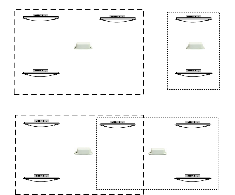
40 System Installation PLUS System Manual
Proprietary Information: Do not disclose unless authorized under a Nondisclosure Agreement and the Partner Agreement.
1
3
2 4
5
A B
Figure 2-30: Inadequate Calibration Tag Coverage
1
3
2 4
5
A B
Figure 2-31: Adequate Calibration Tag Coverage
Select locations for Calibration Tags where they can be heard reliably by as many Readers as
possible. However, be careful to avoid paths that are subject to blockage, reflections, and grazing
angles through walls. Mount the Calibration Tags horizontally whenever possible. Ceiling mounted
tags generally do not propagate as far as tags mounted 1-2’ lower than ceiling height.
2.5.2 Checking Calibration Tag Statistics
In this step we will check the RX%, RSSI, and TDOA for the Readers that we intend to calibrate with
a given Calibration Tag. RX% is a measurement of data throughput of one Tag to one Reader – it
provides the ratio of the number of packets received to the number of packets sent, expressed as a
percentage. RSSI is the Received Signal Strength Indicator, an arbitrary measurement of Tag signal
strength on a scale from 0 to 255. TDOA is the Time Difference of Arrival of the tag signal as
compared between two Readers. The TDOA for a stationary Tag with a good signal path should
change very little.
After placing a Calibration Tag in its candidate location, open the Visualizer Tag Configuration
window from the Settings menu. Locate the ID of the Calibration Tag in the list. Under the Cal Tag
column, select ―Yes‖ to indicate that this is a Calibration Tag. Since this is a test case, it is not
necessary to enter survey information at this time. Or, you may wish to enter an approximate location
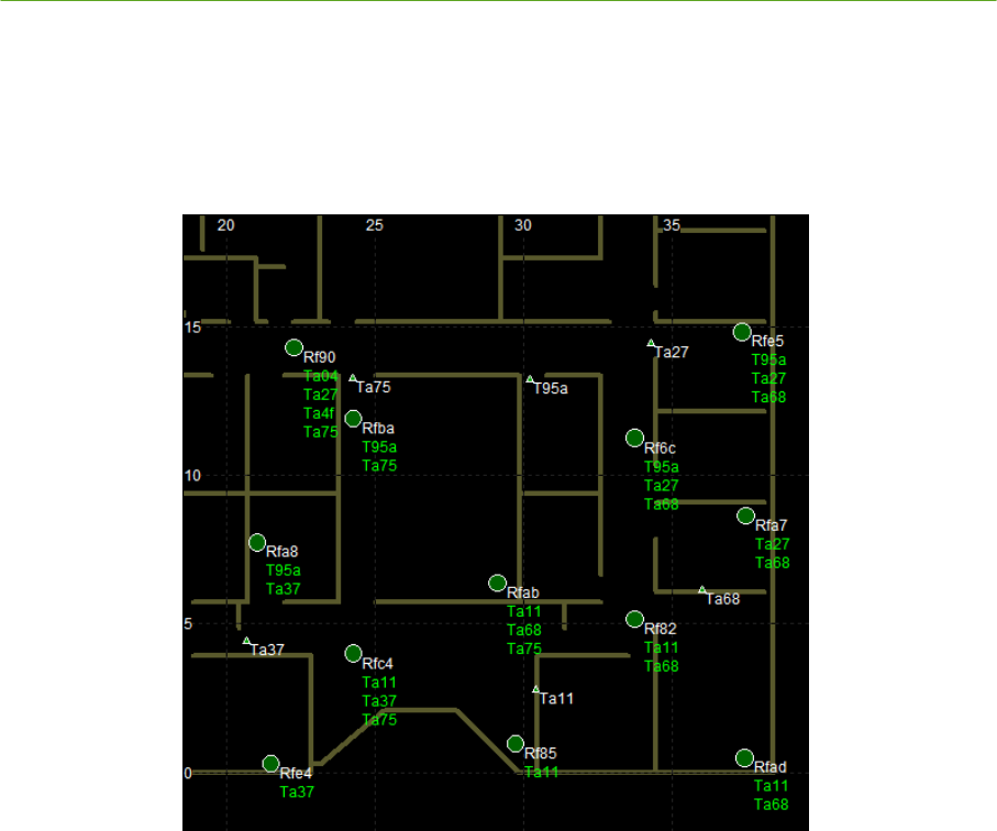
PLUS System Manual System Installation 41
Proprietary Information: Do not disclose unless authorized under a Nondisclosure Agreement and the Partner Agreement.
to have a visual reference on the map. If you decide to keep the tag in this location, don’t forget to
update the survey with accurate information!
Open the Calibration window by clicking the Calibrate button in the tool bar, then enable the
Calibration Assist mode from the Options menu (Figure 2-32).
Figure 2-32: Calibration Assist Mode
Beside each Reader icon in the MapView display, the IDs of all Calibration Tags that can be heard
reliably by that Reader (~85% or better throughput) are displayed in green text. Use this display for a
quick look at coverage. If the Calibration Tag cannot be heard by the intended group of Readers,
relocate it. Turn the Calibration Assist mode off and back on to clear statistics.
As an additional confirmation of throughput, check the RX% and RSSI values for the tag. Open the
Tag Stats window from the View menu, select the Tag ID, and clear the statistics. Allow the statistics
to accumulate for several seconds. Confirm that the Readers of interest can receive the Tag with good
throughput (80% or higher) and good RSSI (typically 100 or higher).
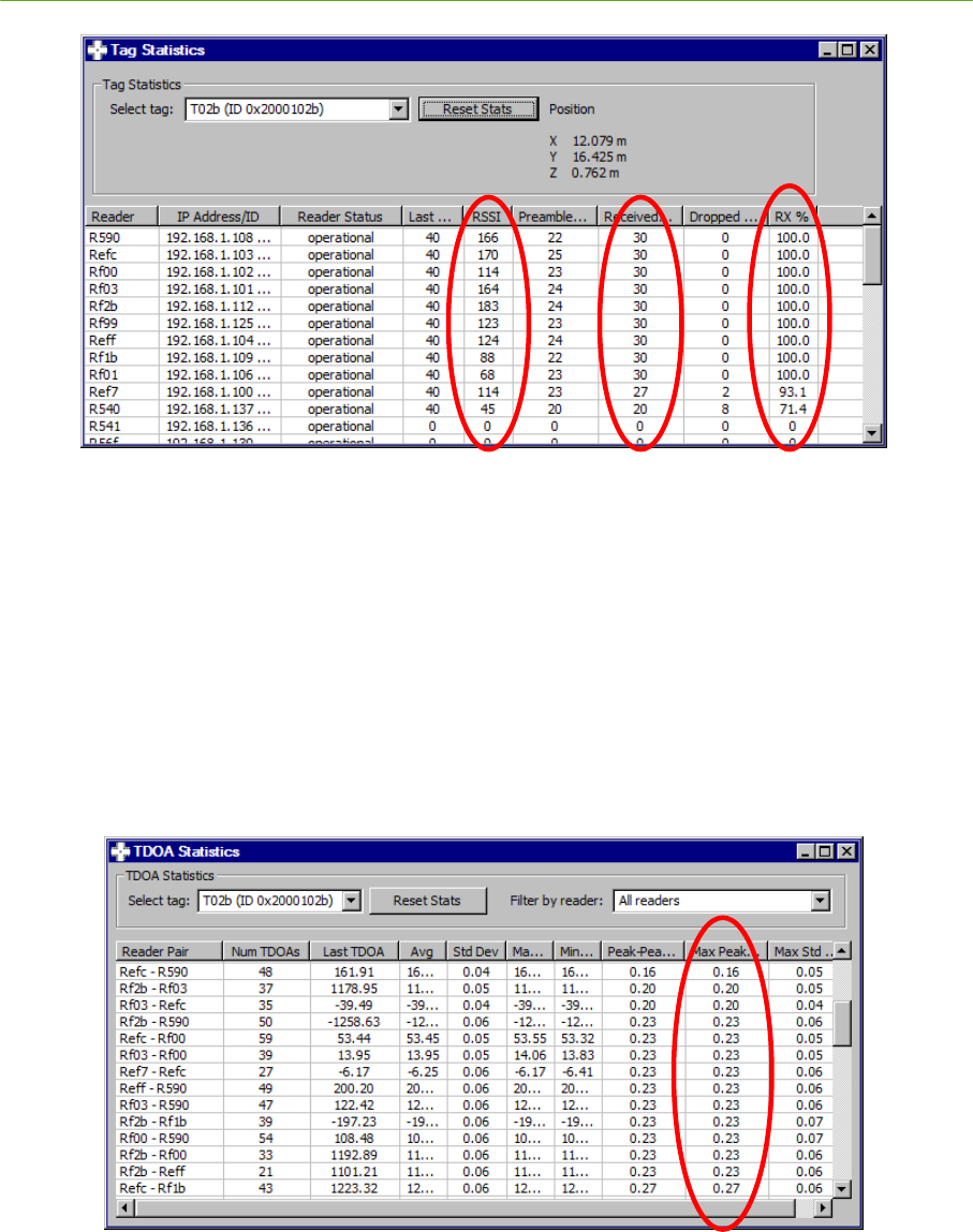
42 System Installation PLUS System Manual
Proprietary Information: Do not disclose unless authorized under a Nondisclosure Agreement and the Partner Agreement.
Figure 2-33: Tag Statistics
Next, check the TDOA stability, which is very important for reliable calibration. Open the TDOA
Stats window under the View menu. Select the Tag ID and clear the statistics. You may also wish to
select a specific Reader using the Filter by reader pull-down box to reduce the amount of data
presented. Allow the statistics to accumulate for several seconds, and then monitor the TDOA values
shown in the Max Peak-Peak column. Ideally, the Max Peak-Peak for a Calibration Tag should not
exceed 1 ns for the intended Reader pairs. Make note of the Reader pairs that produce good results, as
these will be specified in software for use during calibration. It is normal for some Readers to produce
large TDOA results if they are relatively far away from the Tag or if they are affected by signal
blockage. These less desirable Reader combinations should not be used for calibration.
Figure 2-34: TDOA Statistics
2.5.3 Setting up Reader-Tag Associations
Checking the throughput and TDOA statistics for each Calibration Tag will show which Readers can
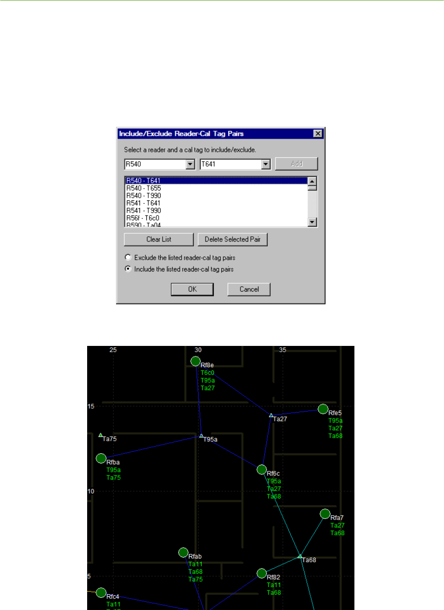
PLUS System Manual System Installation 43
Proprietary Information: Do not disclose unless authorized under a Nondisclosure Agreement and the Partner Agreement.
use a given Calibration Tag reliably. Next, you should enter your list of reliable Tag-Reader
combinations into Visualizer to enable robust calibration.
Click the Calibrate button to open the Calibration window. Under the Options menu, open the Set
tag-reader associations selection. Use the pull-down lists for Readers and Tags to add the desired
combinations to the list. Make sure that the Include the listed Reader-Cal Tag radio button is
checked so that only the specified combinations will be used for calibration. Click OK when
complete. To check that the correct associations were made, turn on the Calibration Assist mode
from the Options menu, and verify that a line has been drawn between correct Tags and Readers.
Figure 2-35: Tag-Reader Associations
Figure 2-36: Tag-Reader Associations Shown in Cal Assist Mode
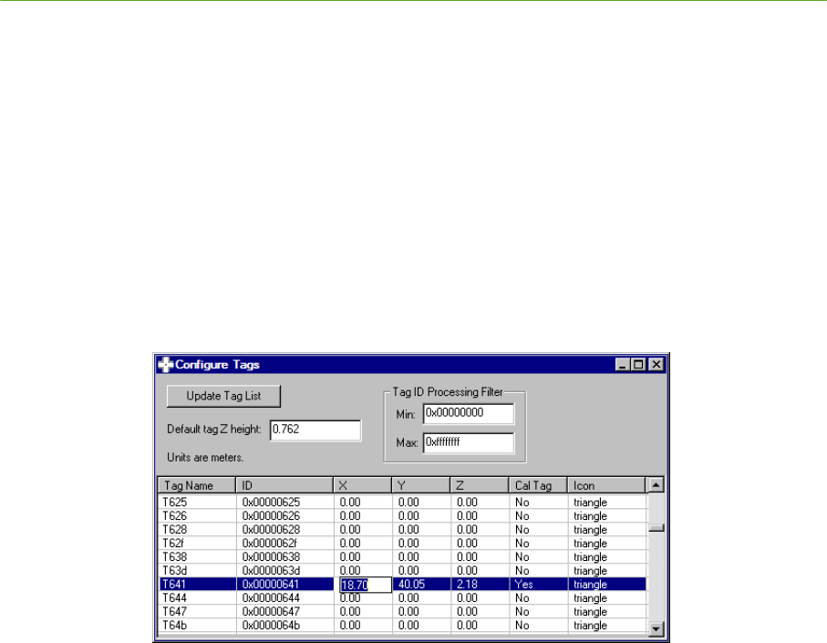
44 System Installation PLUS System Manual
Proprietary Information: Do not disclose unless authorized under a Nondisclosure Agreement and the Partner Agreement.
2.5.4 Calibration Tag Survey and Configuration
After the location of a Calibration Tag has been finalized, survey its position using the same approach
that was used to survey Reader locations. Record the Tag ID and X, Y, Z coordinates for each
Calibration Tag.
Continue to place and verify Calibration Tags until one or more groups of Readers has been covered
with adequate overlap. Use the PLUS Installation Worksheet to record Calibration Tag IDs and
location data.
Open the Tag Configuration window from the Visualizer Settings menu. Locate the ID of each
Calibration Tag, and under the Cal Tag column, select Yes. Under the X, Y, and Z columns, enter
the surveyed coordinates for the Tag. Be sure that the units match the selected English or Metric
settings. Verify that only the Calibration Tags in the list have Yes selected under the Cal Tag
column. When finished, close the Tag Configuration window and save the configuration.
Figure 2-37: Tag Configuration
2.5.5 Calibrate the System
After Calibration Tags have been placed and verified for one or more groups, follow the procedure
below to calibrate those groups.
1) On the button toolbar, click the Calibrate button to open the Calibration window.
2) Select the desired group, or set of groups, and move them to the Calibrate text box using the
direction arrows. You may wish to click the Display selected radio button to only show these
groups in the map display.
3) In the Calibrate frame, enter a Duration of 10 or greater. Longer calibrations (up to 60 seconds)
are preferable, but make sure that the environment is not changing during the calibration interval.
Calibration intervals of less than 10 seconds may result in less accurate results.
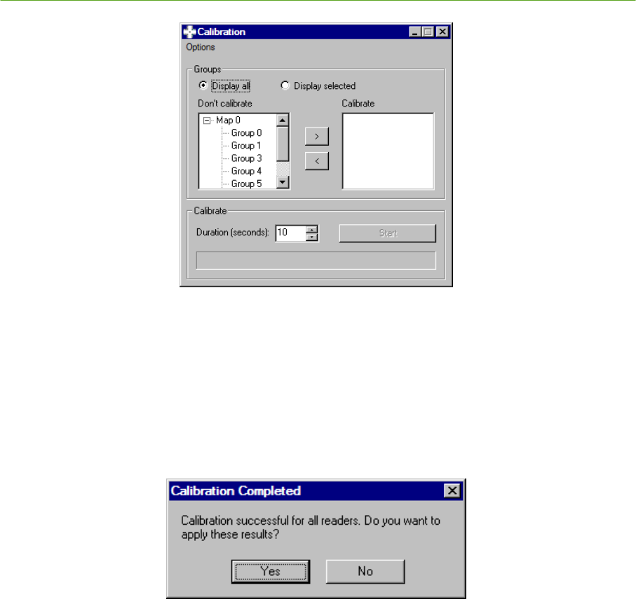
PLUS System Manual System Installation 45
Proprietary Information: Do not disclose unless authorized under a Nondisclosure Agreement and the Partner Agreement.
Figure 2-38: Calibration Window
4) Click the Start button to calibrate the system.
5) While the system is calibrating, the progress bar will increment and the control button will
display Stop. When calibration is complete, a popup window will provide results for the
calibration. If calibration is successful, you should apply the calibration results. A calibration
report will provide status of the calibrated readers.
Figure 2-39: Successful Calibration
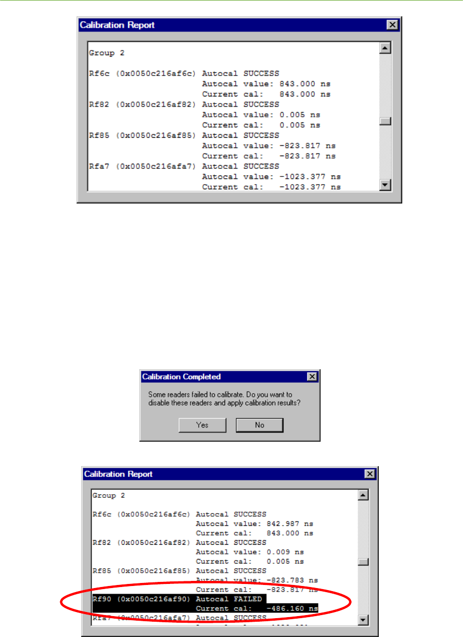
46 System Installation PLUS System Manual
Proprietary Information: Do not disclose unless authorized under a Nondisclosure Agreement and the Partner Agreement.
Figure 2-40: Calibration Report – All Readers Calibrated
6) If calibration fails, click No on the Calibration Completed popup, and check the calibration report
to determine which Readers failed. Re-check the statistics (RX%, RSSI, and TDOA) for any
Readers that failed to calibrate. Adjust tag positions or add new calibration Tags if necessary to
provide adequate coverage for the failed Readers. It may also be possible to adjust the Readers
that are members of the group to provide for better stitching (but don’t sacrifice coverage or
Reader geometry if you redefine the group).
In the figures below, Reader Rf90 failed to calibrate because the calibration results could not be
stitched to other Readers in its group.
Figure 2-41: Readers Failed to Calibrate
Figure 2-42: Reader Rf90 Fails to Calibrate
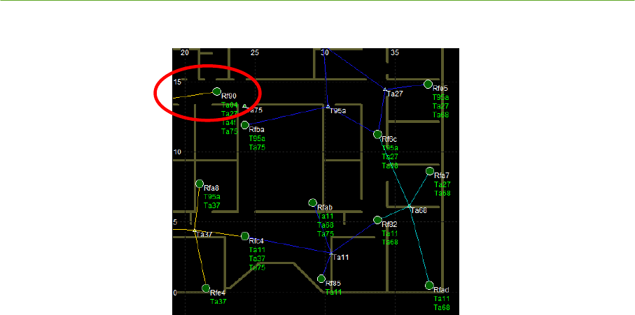
PLUS System Manual System Installation 47
Proprietary Information: Do not disclose unless authorized under a Nondisclosure Agreement and the Partner Agreement.
Figure 2-43: No Stitching to Reader Rf90
7) After each group is successfully calibrated, save the current configuration containing the new
calibration results using the File menu Save Config or Save Config As… selections. The next
time Visualizer is run, it will restore the saved calibration settings without the need to repeat the
calibration process.
Repeat the calibration process until all groups in the system are calibrated. As you finish calibrating
each group, the Visualizer 2D MapView display and statistics screens may be used to monitor Tags in
the areas covered by those groups. Note that good Calibration Tag statistics are necessary but not
sufficient to guarantee a good calibration. The quality of the calibration should be verified by
observing locations of tags throughout the installation.
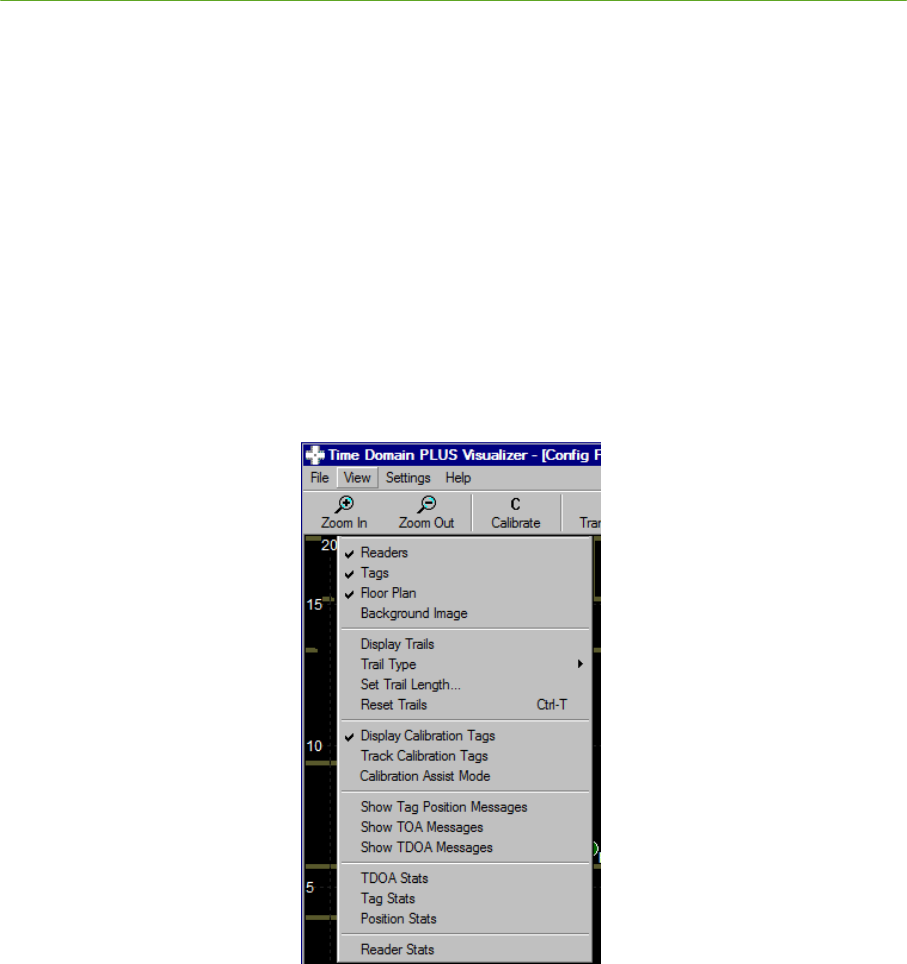
48 System Installation PLUS System Manual
Proprietary Information: Do not disclose unless authorized under a Nondisclosure Agreement and the Partner Agreement.
2.6 Monitoring Location Performance
This section describes Visualizer features and settings that are commonly used to monitor the tracking
performance of the system. A more complete description of Visualizer features is provided in Section
5 PLUS Visualizer of this manual.
2.6.1 Viewing Calibration Tags
After calibration, you may wish to compare the calculated Calibration Tag position to the surveyed
Calibration Tag position. Under the View menu, check Track calibration tags to show Tag icons at
the calculated positions. Uncheck this setting to show Tag icons at the surveyed positions as set in
the Tag Configuration.
During normal operation, you may wish to only view the icons for the other (non-Calibration) Tags in
the system. Check or uncheck the Display calibration tags setting in under the View menu to show
or hide Calibration Tag locations.
Figure 2-44: Tracking and Displaying Calibration Tags
2.6.2 Tag Statistics
In order to calculate an accurate position for a given Tag, at least three Readers must be able to hear
that Tag reliably. If a Tag is not being tracked reliably, coverage can be assessed by observing its
throughput statistics. Open the Tag statistics window by selecting Tag Stats under the View menu.
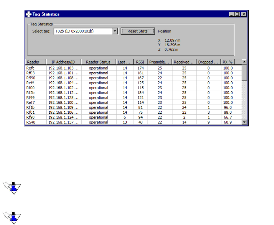
PLUS System Manual System Installation 49
Proprietary Information: Do not disclose unless authorized under a Nondisclosure Agreement and the Partner Agreement.
Figure 2-45: Tag Statistics
Pull down the Select Tag box to select the ID of the Tag you wish to monitor. Click the Reset
button, and allow statistics to accumulate. The received statistics for each Reader in the system can
then be observed.
For a Tag in a given location, the nearest Readers are most significant in calculating a position. The close-by
Readers should show good statistics. Tag statistics observed on Readers that are far away will show low signal
strength and throughput.
Click on the RX% to sort RX% high to low, or low to high. Click on the Reader column to sort the Readers by
name.
For the Readers that are closest to the Tag being observed, check that the Received Signal Strength
Indicator (RSSI) is adequate. RSSI values of 100 or higher are best for calculating a good position.
The Received and Dropped columns show the number of Tag packets that were received or dropped
by a given Reader. The percentage of packets that were received correctly is shown in the RX%
column. Higher confidence locations will result when the RX% is 80% or higher.
2.6.3 Time Difference of Arrival (TDOA) Statistics
When a Reader receives a Tag transmission, it calculates an accurate timestamp to mark the time at
which the packet arrives. A single timestamp is called the Time of Arrival (TOA) for that packet.
When two timestamps generated by two different Readers are compared, the difference in the two
values is called the Time Difference (or Delay) of Arrival (TDOA). Each TDOA value describes a
line on a 2D map. The intersection of two or more of these lines is used to determine the position of a
Tag.
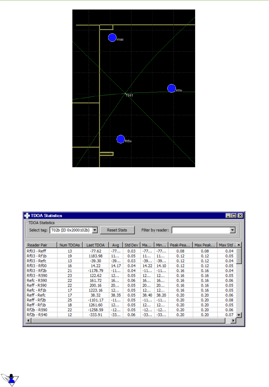
50 System Installation PLUS System Manual
Proprietary Information: Do not disclose unless authorized under a Nondisclosure Agreement and the Partner Agreement.
Figure 2-46: Intersection of TDOA Lines at the Tag Location
Under the Visualizer View menu, select TDOA Stats to observe the TDOA values between each pair
of Readers.
Figure 2-47: TDOA Statistics
Pull down the Select Tag box to select the Tag ID you wish to observe. Click the Reset Stats button
to clear the TDOA statistics for that Tag. Allow the statistics to accumulate.
The TDOA statistics should be observed for a stationary Tag. Tags in motion will show varying TDOA values,
removing any consistency from the statistics being observed.
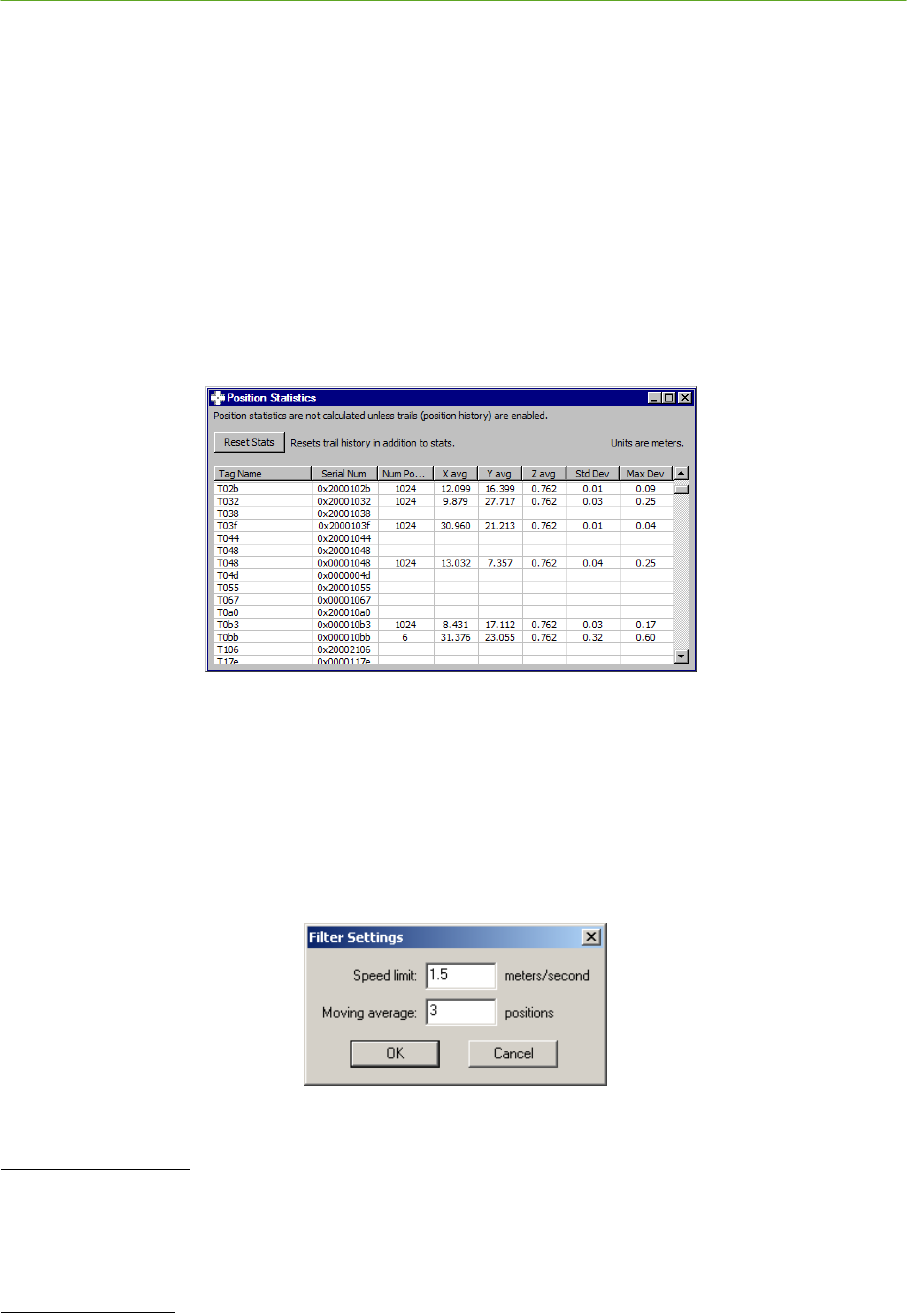
PLUS System Manual System Installation 51
Proprietary Information: Do not disclose unless authorized under a Nondisclosure Agreement and the Partner Agreement.
TDOA statistics are displayed in nanoseconds. The most significant results in the TDOA Statistics
window are the Peak-Peak and Max Peak-Peak columns. The Peak-Peak column shows the peak
variation in the TDOA value over the last 1024 values. The Max Peak-Peak column shows the
maximum TDOA variation seen since the statistics were reset. Optimum positioning performance will be
achieved when the Peak-Peak TDOA values for a given Tag are in the range of 1 nanosecond or less.
2.6.4 Position Statistics
To observe position statistics for a given Tag, first enable the Display Trails option under the View
menu. Next, open the Position Statistics window by selecting Position Stats under the View menu.
Click the Reset Stats button, and allow the statistics to accumulate. The average X and Y calculated
coordinate values are shown, as well as the standard deviation for the last 1024 values and Maximum
standard deviation from the time statistics were reset. The average Z result will be the value entered
in the Tag configuration.
Figure 2-48: Position Statistics
2.6.5 Filtering
The signal from a Tag in a dynamic environment is sometimes subject to blockage and multipath,
causing an erroneous position result. Speed Limit Filtering can be used to condition the position
results such that the position from one update to the next cannot exceed a specified rate of motion.
Averaging Filtering can also be used to average a given number of positions to smooth the position
estimate. To set the filter parameters, select Filter Settings… under the Settings menu.
Figure 2-49: Filter Settings
Speed Limit Filtering
To disable the Speed Limit Filter, enter a value of 0 for Speed limit.
To enable the Speed Limit Filter, enter a value of 1.5 meters/second for normal walking speed. You
may wish to experiment with different filter settings for Tags moving at different rates.
Averaging Filtering
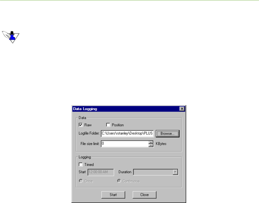
52 System Installation PLUS System Manual
Proprietary Information: Do not disclose unless authorized under a Nondisclosure Agreement and the Partner Agreement.
To disable the Averaging Filter, enter a value of 0 for Moving average positions.
To enable the Averaging Filter, enter a value of 2 or more.
The maximum number of moving average positions allowed is 20. Therefore, the number of positions must
be between 2 and 20. NOTE that using 1 position has no filtering effect.
2.6.6 Raw Logfile Recording and Playback
To observe and troubleshoot positioning performance, it is often useful to record received Tag data
over a period of time and then replay this data. When recorded Tag data is replayed, it is possible to
enable or disable Readers and change filter settings to check variations in performance. Tag, TDOA,
and Position statistics may also be monitored from a replayed logfile.
To log raw Tag data, select Logging… under the File menu.
Figure 2-50: Data Logging
Make sure that the Raw option is checked. For more information on Position file logging and Timed
logging, see Section 5 PLUS Visualizer of this manual.
Use the Browse button to select a destination for the logfile, and click the Start button. After the
desired data has been captured, click Stop to end the data logging process.
To replay a logfile, select Set Data Input… under the Settings menu. Click the Logfile radio button,
and browse to the destination of the recorded logfile. Select the desired logfile and click Open.
Click OK to begin replaying the logfile.
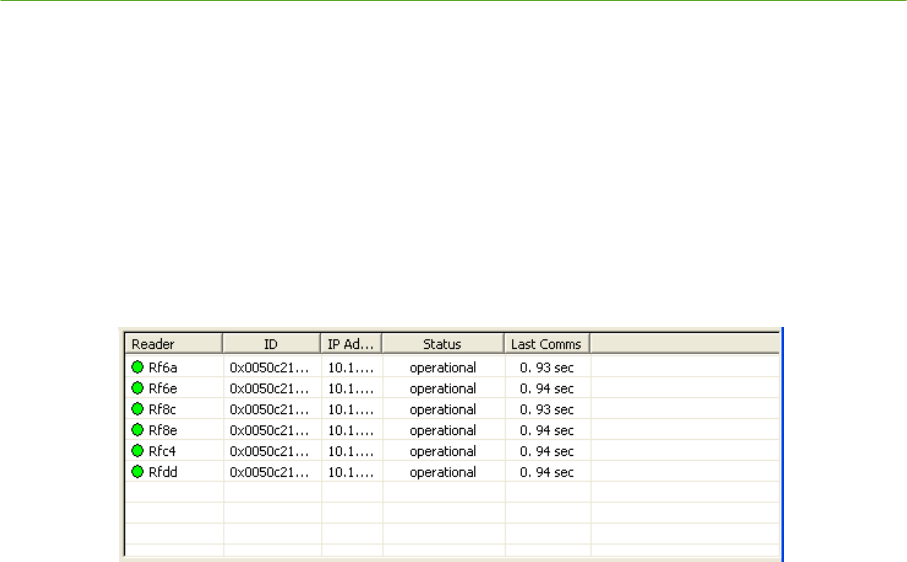
PLUS System Manual System Installation 53
Proprietary Information: Do not disclose unless authorized under a Nondisclosure Agreement and the Partner Agreement.
2.7 Troubleshooting Reader Communications
For cases where the Visualizer is unable to see data from the Readers, follow the troubleshooting
procedure below.
Check that discovery packets are being received from the Readers. Under the Reader List View,
determine if the Last Comms timer is exceeding ten seconds for the Reader(s) in question. If the
timer is resetting to zero after ten seconds, the Visualizer is receiving Reader data, but the Reader is
not seeing Tag packets. Follow the procedure below for the Reader Connectivity but No Tag
Traffic case. If the timer is exceeding ten seconds without resetting, follow the procedure for the No
Reader Connectivity case.
Figure 2-51: Reader List View
2.7.1 No Reader Connectivity
1) Make sure that duplicate instances of the Visualizer application are not running.
2) Check the Ethernet cable connection bewteen the server and Ethernet switch. Typically, the
Ethernet connector will have one LED for link status and one LED for activity. A steady green
LED generally indicates Ethernet connectivity to the next device, and a flashing yellow LED
indicates Ethernet traffic is present. Replace the cable if it is in question.
3) Check the Ethernet cable connection between the Ethernet switch and the SDP. Verify that the
Switch is powered, a valid connection exists, and traffic is present.
4) Check that the Reader is powered, and the Ethernet link status light on the Reader is steady. The
Ethernet activity light should blink each time a Tag packet is received, or once every ten seconds
as a discovery packet is transmitted.
5) Check that the NIC card on the server has been configured with the correct IP address. This IP
address should correspond to the Location Engine IP address configured on each Reader.
6) Check that the Visualizer IP address is set properly under the Settings, Set Data Input… menu.
7) Check that traffic from the Readers is not blocked by the server firewall.
Open a command window (Figure 2-52). Check that there is not another process conflicting with
the location software on port 11000 using the command
netstat –a –p UDP –n –o (Figure 2-53).
8) Check communications to the Reader by typing ping <IP address>.
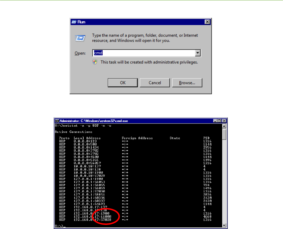
54 System Installation PLUS System Manual
Proprietary Information: Do not disclose unless authorized under a Nondisclosure Agreement and the Partner Agreement.
Figure 2-52: Command Window
Figure 2-53: Check for Port 11000 Conflicts
9) If the Reader responds to the ping request, but data is still not received by the Visualizer, check
and correct the Location Engine IP address on the Reader as described in section 2.3.3
Configuring Reader and Location Engine IP Addresses.
2.7.2 Reader Connectivity but No Tag Traffic
1. Place a known working Tag in proximity to the Reader in question. Check that the Data LED on
the Reader panel is toggling.
2. If the Reader Data LED does not toggle when a Tag is present, disconnect the SMA cable
between the Reader and the Antenna. Place the Tag within one inch of the Reader SMA port. If
the Reader Data LED toggles, replace the SMA cable.
3. If the Reader Data LED does not toggle with the Tag placed next to the SMA connector, cycle
power on the Reader. If the Reader does not receive Packets after rebooting, a hardware failure
has occurred and the Reader should be replaced.
PLUS System Manual System Installation 55
Proprietary Information: Do not disclose unless authorized under a Nondisclosure Agreement and the Partner Agreement.
2.8 Reader Installation Worksheet
MAC Address IP Address Location Notes Reference Walls
X Offset
(m)
Y Offset
(m)
Z (m)
X Coordinates
(m)
Y Coordinates
(m)
SDP to Reader
Cable Length
(m)
Last
Reader
(Y/N)
56 System Installation PLUS System Manual
Proprietary Information: Do not disclose unless authorized under a Nondisclosure Agreement and the Partner Agreement.
2.9 Calibration Tag Installation Worksheet
Tag ID Location Notes Reference Walls X Offset (m) Y Offset (m) Z (m) X Coordinates (m) Y Coordinates (m)
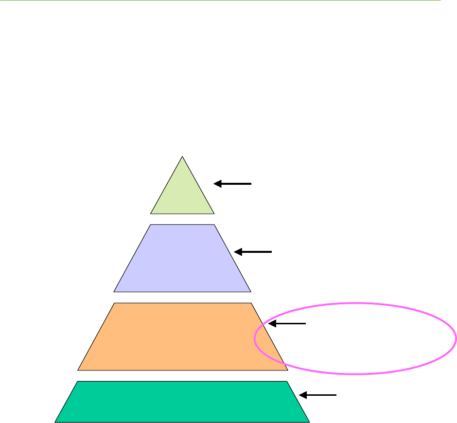
PLUS System Manual Reader Data Interface 57
Proprietary Information: Do not disclose unless authorized under a Nondisclosure Agreement and the Partner Agreement.
3. PLUS Reader Data Interface
3.1 Overview
The PLUS Reader has a 100Base-TX Ethernet connection that allows the Reader to communicate with
other components in the system. This section describes the Tag packet data sent by the Reader over the
Ethernet interface. The Reader will also respond to ASCII commands over the Ethernet interface.
These commands and the Reader responses will be described.
The Reader has a serial port that can be used to configure certain Reader parameters. Connecting to the
serial port and logging on to the Reader to change parameters will also be described.
P L U S L o ca tio n
S o f tw a r e
In sta lla t io n
S o f tw a r e
P L U S R e a d er
P L U S H a r d w a r e In fr a str u c t u r e
S e c t io n 4
P L U S L o c a tio n S o ft w a r e L ib r a r y
H ig h L e v e l S y s te m I n te rfa c e / I n te r f a c e to
L o ca tio n S o ftw a re
S e c t io n 5
P L U S V is u a liz er
V is u a liz e r, I n s ta lla tio n /M a in te n a n c e
S o ftw a r e T o o ls
S e c t io n 3
P L U S R e a d e r D a ta I n te r fa c e
R e a d e r S o ftw a re I n te r fa c e -
C o m m a n d s , R e sp o n s es , R a w T O A
P a ck et D e fin itio n
S e c t io n 2
P L U S S y s t e m I n s ta lla tio n
R e a d e r s, T a g s, S D P , C a b lin g ,
P o w e r , H a r d w a re
C o n fig u r a tio n
P L U S L o ca tio n
S o f tw a r e
In sta lla t io n
S o f tw a r e
P L U S R e a d er
P L U S H a r d w a r e In fr a str u c t u r e
S e c t io n 4
P L U S L o c a tio n S o ft w a r e L ib r a r y
H ig h L e v e l S y s te m I n te rfa c e / I n te r f a c e to
L o ca tio n S o ftw a re
S e c t io n 4
P L U S L o c a tio n S o ft w a r e L ib r a r y
S e c t io n 4
P L U S L o c a tio n S o ft w a r e L ib r a r y
H ig h L e v e l S y s te m I n te rfa c e / I n te r f a c e to
L o ca tio n S o ftw a re
S e c t io n 5
P L U S V is u a liz er
V is u a liz e r, I n s ta lla tio n /M a in te n a n c e
S o ftw a r e T o o ls
S e c t io n 5
P L U S V is u a liz er
S e c t io n 5
P L U S V is u a liz er
V is u a liz e r, I n s ta lla tio n /M a in te n a n c e
S o ftw a r e T o o ls
S e c t io n 3
P L U S R e a d e r D a ta I n te r fa c e
R e a d e r S o ftw a re I n te r fa c e -
C o m m a n d s , R e sp o n s es , R a w T O A
P a ck et D e fin itio n
S e c t io n 3
P L U S R e a d e r D a ta I n te r fa c e
S e c t io n 3
P L U S R e a d e r D a ta I n te r fa c e
R e a d e r S o ftw a re I n te r fa c e -
C o m m a n d s , R e sp o n s es , R a w T O A
P a ck et D e fin itio n
S e c t io n 2
P L U S S y s t e m I n s ta lla tio n
R e a d e r s, T a g s, S D P , C a b lin g ,
P o w e r , H a r d w a re
C o n fig u r a tio n
S e c t io n 2
P L U S S y s t e m I n s ta lla tio n
S e c t io n 2
P L U S S y s t e m I n s ta lla tio n
R e a d e r s, T a g s, S D P , C a b lin g ,
P o w e r , H a r d w a re
C o n fig u r a tio n
Figure 3-1: PLUS Interface Layers – Reader Data Interface
3.2 Network Configuration Options
3.2.1 Reader IP Address
When the Reader is powered on, the operating system (OS) boots and initializes all hardware. The OS
will attempt to acquire an IP address lease from a DHCP server. Once it successfully acquires a lease,
the operational Reader software is started automatically. The Reader may also be configured with a
static IP address, subnet mask, and gateway. Both the RS-232 interface and Ethernet interface provide
mechanisms for changing the Reader IP address configuration.

58 Reader Data Interface PLUS System Manual
Proprietary Information: Do not disclose unless authorized under a Nondisclosure Agreement and the Partner Agreement.
3.2.2 Location Engine IP Address
The default Reader configuration assumes that the location engine IP address is the first IP address in
the subnet. For example, if the acquired IP lease is 10.25.67.100 and the subnet mask is 255.0.0.0, then
the Reader software assumes the location engine IP address is 10.0.0.1. The Reader may also be
configured with a static location engine IP address. The location engine IP address may be specified
through the RS-232 interface and through the Ethernet interface.
3.2.3 Reader Port Assignments
The Reader software listens for Tag packets and sends one Time of Arrival (TOA) packet over the
Ethernet for every Tag packet that is received successfully. The TOA packets are sent as UDP packets
to the location engine's IP address at port 11000. This software also listens for commands on TCP port
11001. The formats for all Ethernet packets are discussed in a following section.
3.3 RS-232 Interface
3.3.1 RS-232 Port Connection Parameters
The Reader RS-232 connection parameters are as follows. Connection to the Reader RS-232 requires a
PS/2 to DB9 adapter.
Baud Rate: 115,200
Data Bits: 8
Parity: none
Stop Bit: 1
Flow Control: none
3.3.2 Terminal Connection Login
Log in to the Reader with username plus and password timedomain.
3.3.3 Terminal Connection Commands
The terminal connection may be used to configure the Reader IP address settings and location engine IP
address. Changes made with the following utilities are written to flash memory.
changeIp starts a command-line menu for configuring the Reader IP address. Menu option 1
configures the Reader to obtain an address automatically from a DHCP server. Menu option 2 allows
the user to set the Reader to a static IP address, subnet mask, and gateway. Pressing Enter exits the
changeIp application without changing the Reader’s IP configuration.
solverIp starts a command-line menu for setting the IP address of the location engine. Menu option 1
configures the Reader to generate the location engine IP address automatically. Menu option 2 allows
the user to set the location engine IP address. Pressing Enter exits the solverIp application without
changing the location engine IP address.
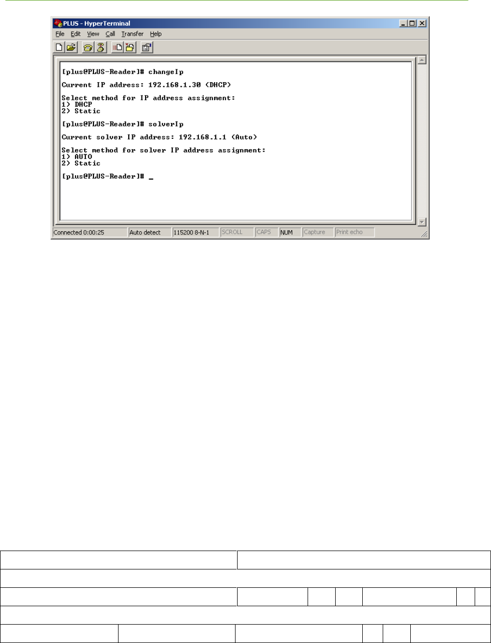
PLUS System Manual Reader Data Interface 59
Proprietary Information: Do not disclose unless authorized under a Nondisclosure Agreement and the Partner Agreement.
Figure 3-2: changeIp and solverIp Commands
3.4 Detailed Interface Description
At startup, the Reader listens for a connection on TCP port 11001. The Reader can be controlled by
sending ASCII commands over this socket. Also, at startup (and subsequently when no Tag
transmission has been heard within 10 seconds), the Reader broadcasts a discovery TOA packet to UDP
port 11000 to announce its presence. The discovery TOA packet is a special form of the TOA packet
with the Tag ID set to zero. Once the Reader has started, it will send a binary TOA packet to UDP port
11000 for each Tag transmission received. The formats of the binary UDP packet and the ASCII TCP
commands are discussed in this section.
3.4.1 TOA Packet Format
The packet format description below follows the commonly used TCP/IP convention of numbering the
most significant bit as bit 0 and the least significant bit as bit 31. Also, packets are transmitted in
network byte order, meaning the most significant byte (bits 0-7) is transmitted first, followed by the
byte at bits 8-15, then bits 16-23, and the least significant byte (bits 24-31) last. This means that on
little endian architectures, multi-byte values will need to be byte swapped before use.
The Reader sends a TOA packet each time it successfully receives a Tag transmission. These packets
are unicast to port 11000 at the location engine’s IP address. The TOA packet consists of 4 32-bit
words, as shown below.
0 15
16 31
Reader ID (bits 0-31)
Reader ID (bits32-47)
Version
BS
BN
Seq Num
M
A
Tag ID
Coarse TOA
Fine TOA
RSSI
T
RS
Preamble Cnt
Figure 3-3: TOA Packet Format

60 Reader Data Interface PLUS System Manual
Proprietary Information: Do not disclose unless authorized under a Nondisclosure Agreement and the Partner Agreement.
Each field in the packet is discussed in detail below:
Reader ID – The Reader’s 48-bit MAC address
Version – 4-bit field that denotes the version of the data format. This document describes
version 2. Each time the format of the TOA packet changes, the version number will also
change.
BS – 2-bit battery status reported by the Tag
BN – 2-bit button event field from the Tag payload. A button event of 0 means that the button
is not pressed. A value of 1 indicates a single button push event. A value of 2 indicates that the
button was pressed twice. A value of 3 indicates a push-and-hold event (the button was
depressed for longer than 2 seconds).
Sequence number – 6-bit sequence number from the Tag payload
M – 1-bit motion detect field from the Tag payload. This field is currently not implemented.
A – 1-bit alarm field that indicates the Reader has encountered an error condition. Additional
information can be found by querying the Reader’s alarm status and statistics.
Tag ID – 32-bit ID of the transmitting Tag. This field will be zero for discovery packets.
Coarse TOA – 8-bit field containing the coarse time-of-arrival value. Each bit represents 10 ns.
This field is undefined if field T below is 1.
Fine TOA – 8-bit field containing the fine TOA value. Each bit represents 1/256 of a 10 ns
coarse interval. Thus, each bit is 39.0625 ps. This field is undefined if field T below is 1.
RSSI – Received Signal Strength Indication. This 8-bit field is an estimate of the received
Tag’s signal strength. The minimum RSSI value is around 20, and the strongest compressed
signals peak at approximately 230.
T – 1-bit field that indicates valid Coarse and Fine TOA values. A value of 0 indicates a valid
TOA. A value of 1 indicates an invalid TOA and the Coarse and Fine TOA fields are
undefined.
RS – 2-bit field reserved for future use.
Preamble Cnt – 5-bit field that indicates how many bits remained in the acquisition preamble
after the acquisition threshold was passed. Higher numbers indicate stronger signals. Valid
values range from 17-23.
An example structure declaration in the C programming language that would hold a TOA packet is as
follows:
struct toa
{
char readerId[6]; /* reader ID */
char versionBsBn; /* version, battery status, and button event */
char seqNumMA; /* sequence number, motion detect, and alarm */
int tagId; /* tag ID */
char coarseToa; /* coarse TOA value */
char fineToa; /* fine TOA value */
char rssi; /* received signal strength indicator */

PLUS System Manual Reader Data Interface 61
Proprietary Information: Do not disclose unless authorized under a Nondisclosure Agreement and the Partner Agreement.
char toaPcnt; /* TOA status and preamble count */
};
The tagId field in the structure above will be received in reverse byte order on little endian machine
architectures (e.g., Intel-based PCs) and will need to be byte-swapped.
The Reader sends a special form of the TOA packet, called a discovery TOA packet, to the network
broadcast address after initial startup. The format of the discovery TOA packet is identical to the
normal TOA packet, except the Tag ID field is set to zero. The Reader waits a small random delay after
startup before sending the initial discovery TOA packet to avoid packet storms when many readers start
at the same time (for example, after a power outage). Also, any time the Reader does not have any
normal TOA packets to transmit in a 10 second period, it will transmit a discovery TOA packet to the
location engine’s address.
3.4.2 Commands and Responses
The Reader can be controlled by sending ASCII commands over TCP port 11001. Some commands
cause the Reader to reply with an ASCII response packet. The Reader can receive either upper case or
lower case ASCII commands, and will always respond in upper case. All command and response
packets are terminated by a carriage return-line feed combination. Specific command formats are
described below.
3.4.2.1 Reader Commands
The following table lists the commands that can be sent to a Reader to command it to perform a function.

62 Reader Data Interface PLUS System Manual
Proprietary Information: Do not disclose unless authorized under a Nondisclosure Agreement and the Partner Agreement.
Command
Meaning
RX 1
Enable the Reader. This causes the Reader to start listening
to Tag packets. The Reader is automatically enabled at
startup.
RX 0
Disable Reader. The Reader will stop listening for Tag
packets.
CAL 1
Enable power to Calibration Tag.
CAL 0
Disable power to Calibration Tag. Power to the Calibration
Tag is disabled at startup.
IP DHCP
Configure the Reader to acquire its IP address via DHCP.
IP ipaddr:mask[:gw]
Configure the Reader to use the static IP address ipaddr,
subnet mask mask, and gateway gw. The gateway parameter
is optional.
SOLVER AUTO
Configure the Reader to generate the location engine IP
address based on the Reader’s IP address and netmask.
SOLVER addr
Set IP address of location engine to addr. The Reader sends
all TOA packets to the location engine’s IP address.
OSC 1
Enable the internal oscillator. The internal oscillator should
be enabled when Reader is not connected to a SDP.
OSC 0
Disable the internal oscillator. The internal oscillator should
be disabled when Reader is connected to a SDP.
REBOOT
Reboot Reader.
SENDSTATUS
Causes Reader to reply with current status.
SENDVER
Causes Reader to reply with software and firmware version
information.
SENDSTATUSVER
Causes Reader to reply with status and version information.
SENDSTATS
Causes Reader to send statistics.
CLEARSTATS
Causes Reader to reset statistics fields to 0.
SENDALARMSTATUS
Causes Reader to send alarm status word.
SENDALARMENABLE
Causes Reader to send alarm enable word.
SETALARMENABLE a
Sets Reader’s alarm enable word to a.
CLEARALARM a
Clears alarm condition(s) a in Reader.
Figure 3-4: Reader Commands
The values specified by the IP, SOLVER, OSC, and SETALARMENABLE commands are stored in
flash and are persistent across reboots.

PLUS System Manual Reader Data Interface 63
Proprietary Information: Do not disclose unless authorized under a Nondisclosure Agreement and the Partner Agreement.
3.4.2.2 Reader Responses
Several of the commands listed in the previous section cause the Reader to reply with a response string.
These responses are discussed below.
SENDSTATUS
The SENDSTATUS command causes the Reader to send its current control settings. The format of
the reply is:
RX r, CAL c, TERM t, IP addr:mask:gw, SOLVER saddr, OSC o
Where r indicates whether the Reader is enabled (0 = disabled, 1 = enabled), c is the Calibration
Tag power setting, t is the Ethernet termination setting (the last Reader in the Ethernet chain will be
terminated), addr is the static IP address of the Reader, mask is the subnet mask, gw is the gateway
address, saddr is the IP address of the location engine, and o indicates whether the internal
oscillator is enabled. If the Reader is configured to use DHCP, the field following the ―IP‖ will be
―DHCP‖. For example, if the Reader is enabled, the Calibration Tag power is disabled, the
Ethernet termination is disabled, the Reader has a fixed IP address of 10.1.4.5, the subnet mask is
255.255.255.0, the gateway address is 10.1.4.1, the location engine’s IP address is 10.1.4.1, and the
internal oscillator is disabled, a SENDSTATUS command will cause the Reader to reply with:
RX 1, CAL 0, TERM 0, IP 10.1.4.5:255.255.255.0:10.1.4.1, SOLVER 10.1.4.1, OSC 0
If, in the previous example, the Reader is configured for dynamic instead of static IP and the
location engine IP is automatically generated by the Reader, a SENDSTATUS command will cause
the Reader to reply with:
RX 1, CAL 0, TERM 0, IP DHCP, SOLVER AUTO, OSC 0
SENDVER
The SENDVER command causes the Reader to reply with the versions of the FPGA firmware and
the embedded software. The format of the response is:
FPGA 0xd051, SW 1.1
SENDSTATUSVER
The SENDSTATUSVER command causes the Reader to reply with the status, as sent by the
SENDSTATUS command, and the version information, as sent by the SENDVER command:
RX 1, CAL 0, TERM 0, IP DHCP, SOLVER AUTO, OSC 0, FPGA 0xd051, SW 1.1
SENDSTATS
The Reader maintains internal cumulative counts of certain statistics. The SENDSTATS command
causes the Reader to reply with a snapshot of these statistics, along with the Reader’s internal
temperature. The general format of the response is:
PKT p, CRC c, FD d, FO o, TOA a, UP u, TEMP t, PLL l, SYNC s
The statistics reported by the Reader include the number of packets received correctly (p), number
of packets received with CRC error (c), number of false detections (d), number of FIFO overflows
(o), number of packets received that resulted in bad TOA calculations (a), Reader uptime in seconds
(u), temperature t in degrees Celsius, number of PLL unlocked events (l), and number of sync
marker error events (s). A specific example is:
PKT 1000, CRC 5, FD 2, FO 0, TOA 10, UP 1000000, TEMP 30.5, PLL 0, SYNC 0

64 Reader Data Interface PLUS System Manual
Proprietary Information: Do not disclose unless authorized under a Nondisclosure Agreement and the Partner Agreement.
In this example, the Reader replied with the following statistics: 1000 packets received correctly, 5
packets received with incorrect CRC, 2 false detections, no FIFO overflows, 10 packets received
that produced bad TOA calculations, an uptime of 1000000 seconds, a temperature of 30.5 degC,
the PLL was never unlocked, and no sync marker errors have occurred. Internally, the Reader
keeps all statistics in unsigned 32-bit integers. The statistics counters will wrap around to zero and
continue incrementing if they overflow.
The alarm commands and their responses are discussed in the following section.
3.4.3 Reader Alarms
As described previously, the TOA packet includes a bit that is used to indicate Reader alarms. An
alarm is any error condition in the Reader that may require corrective action. Internally, the Reader
maintains both a status word that shows what alarms, if any, have been generated, and an enable word
which enables/disables the Reader’s setting the alarm bit in the TOA packet.
The alarm status word is a 32-bit word, each bit of which corresponds to an alarm source. See Figure
3-5: Alarm Status and Alarm Enable Word Bit Position Definition for the bit definition of the alarm
sources. It always shows the current status of an alarm source, even if the alarm source has been
disabled via the alarm enable word described below. A ―1‖ in a bit position indicates that an alarm has
been generated for the corresponding alarm source; a ―0‖ indicates no alarm exists for the
corresponding alarm source. The alarm status word is read using the SENDALARMSTATUS
command. Once an alarm source causes its alarm bit in the TOA packet to be set, the bit will remain
set until the alarm source is cleared using the CLEARALARM command. This command takes a
single parameter, which is the bit mask of the alarm sources to clear.
The alarm enable word is also a 32-bit word, and has the same alarm source bit definitions as the alarm
status word. In the alarm enable word, a ―1‖ in a bit position indicates that the corresponding alarm
source is enabled, and, if an alarm on that source occurs, the alarm bit in the TOA packet will be set. A
―0‖ in a bit position in the alarm enable word means that the alarm source is disabled – even if an alarm
condition occurs on that source, the Reader will not set the alarm bit in the TOA packet . The alarm
enable word can be read and written using the SENDALARMENABLE and SETALARMENABLE
commands.
At startup, the Reader sets the alarm enable word to the value that was last set by the
SETALARMENABLE command. If the alarm enable word has never been set using this command,
the alarm enable word is set to 0xFFFFFFFF (all alarms are enabled). Every time the Reader sends a
TOA packet, the alarm bit is set if an alarm source is set in both the alarm status word and the alarm
enable word.

PLUS System Manual Reader Data Interface 65
Proprietary Information: Do not disclose unless authorized under a Nondisclosure Agreement and the Partner Agreement.
The bit definitions in the alarm status and alarm enable words are as follows:
Bit Position
Alarm Source
Meaning
0
PLL Lock Lost
The Reader lost synchronization with the SDP. The Reader will
need to be recalibrated.
1
Reboot
The Reader has rebooted. When a PLUS system is initially
powered on, all readers will report this alarm and the alarm should
be cleared. After initial power up, this alarm indicates a loss of
power or other Reader problem. The Reader will need to be
recalibrated.
2
Sync Marker Error
This alarm indicates a problem with the sync marker from the SDP.
3-31
Reserved
Figure 3-5: Alarm Status and Alarm Enable Word Bit Position Definition
The following example shows the recommended processing flow to handle alarms. In this example, a
Reader is reporting a ―PLL Lock Lost‖ alarm.
10) TOA packet is received with alarm bit set. All subsequent TOA packets from this
Reader will continue to have the alarm bit set until the alarm is cleared.
11) Reader alarm status is queried using the following command:
SENDALARMSTATUS
12) Reader responds with 32-bit hexadecimal alarm status indicating that the ―PLL
Lock Lost‖ alarm is present:
0x00000001
13) Reader is commanded to clear the alarm condition:
CLEARALARM 0x00000001
If a Reader is being used to detect Tag presence only and not connected to a SDP, the ―PLL Lock Lost‖
alarm and the ―Sync Marker Error‖ alarm may be ignored:
SETALARMENABLE 0xFFFFFFFA
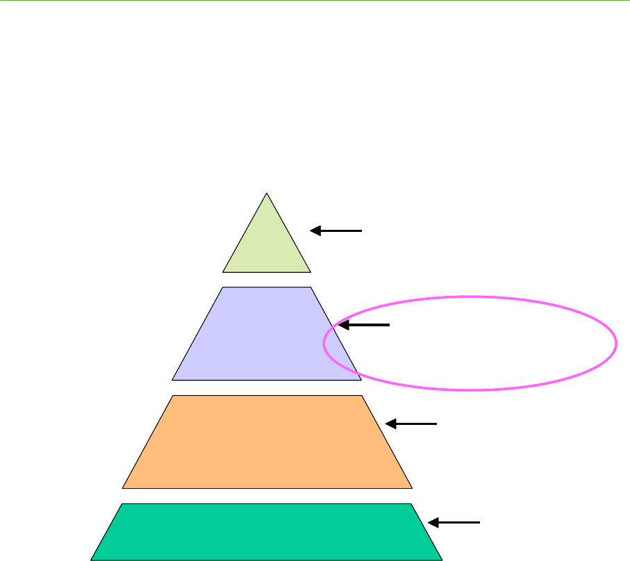
66 Location Software Library PLUS System Manual
Proprietary Information: Do not disclose unless authorized under a Nondisclosure Agreement and the Partner Agreement.
4. PLUS Location Software Library
4.1 Introduction
This section documents the functions, properties, and events provided by the PLUS™ Tracker OCX
software layer. Time Domain customers interested in developing software to utilize TOA data from the
PLUS Readers or recorded data from Time Domain’s tracking component can do so via this OCX
library.
P L U S L o c a tio n
S o f tw a r e
In st a lla t io n
S o f tw a r e
P L U S R e a d e r
P L U S H a r d w a r e I n fr a str u c tu r e
S e c tio n 4
P L U S L o c a tio n S o ft w a re L ib r a r y
H ig h L e ve l S y s te m I n te rf a c e / I n te rf a c e to
L o ca tio n S o ftw a r e
S e c tio n 5
P L U S V is u a liz e r
V is u a liz e r, I n s ta lla tio n /M a in te n a n c e
S o f tw a re T o o ls
S e c tio n 3
P L U S R e a d e r D a ta I n te r fa c e
R e a d e r S o f tw a re I n te r fa c e -
C o m m a n d s, R e s p o n s e s, R a w T O A P a ck e t
D e fi n itio n
S e c tio n 2
P L U S S y st e m I n s ta lla tio n
R e a d e r s , T a g s , S D P , C a b lin g ,
P o w e r , H a rd w a re
C o n fig u r a tio n
P L U S L o c a tio n
S o f tw a r e
In st a lla t io n
S o f tw a r e
P L U S R e a d e r
P L U S H a r d w a r e I n fr a str u c tu r e
S e c tio n 4
P L U S L o c a tio n S o ft w a re L ib r a r y
H ig h L e ve l S y s te m I n te rf a c e / I n te rf a c e to
L o ca tio n S o ftw a r e
S e c tio n 4
P L U S L o c a tio n S o ft w a re L ib r a r y
S e c tio n 4
P L U S L o c a tio n S o ft w a re L ib r a r y
H ig h L e ve l S y s te m I n te rf a c e / I n te rf a c e to
L o ca tio n S o ftw a r e
S e c tio n 5
P L U S V is u a liz e r
V is u a liz e r, I n s ta lla tio n /M a in te n a n c e
S o f tw a re T o o ls
S e c tio n 5
P L U S V is u a liz e r
S e c tio n 5
P L U S V is u a liz e r
V is u a liz e r, I n s ta lla tio n /M a in te n a n c e
S o f tw a re T o o ls
S e c tio n 3
P L U S R e a d e r D a ta I n te r fa c e
R e a d e r S o f tw a re I n te r fa c e -
C o m m a n d s, R e s p o n s e s, R a w T O A P a ck e t
D e fi n itio n
S e c tio n 3
P L U S R e a d e r D a ta I n te r fa c e
S e c tio n 3
P L U S R e a d e r D a ta I n te r fa c e
R e a d e r S o f tw a re I n te r fa c e -
C o m m a n d s, R e s p o n s e s, R a w T O A P a ck e t
D e fi n itio n
S e c tio n 2
P L U S S y st e m I n s ta lla tio n
R e a d e r s , T a g s , S D P , C a b lin g ,
P o w e r , H a rd w a re
C o n fig u r a tio n
S e c tio n 2
P L U S S y st e m I n s ta lla tio n
S e c tio n 2
P L U S S y st e m I n s ta lla tio n
R e a d e r s , T a g s , S D P , C a b lin g ,
P o w e r , H a rd w a re
C o n fig u r a tio n
Figure 4-1: PLUS Interface Layers – Location Software Library
The OCX is developed in Microsoft Visual Studio 2005 using Microsoft Foundation Classes (MFC)
and C++. It comprises one COM object: Tracker. The Tracker object handles the actual messages from
the PLUS Readers and uses the information from the Readers to calibrate, solve, and maintain
information about the Tags, Readers, and Calibration Tags.
This section describes each of the software interfaces of the PLUS Location Software Library in detail.
Section 4.2 provides an overview of the Tracker Object. Section 4.3 explains the some of the
terminology used in the Location Software. Section 4.4 describes alternatives for initializing the
Location Software. Section 4.5 is a complete reference for all features in the API. Section 4.6
documents the format of the raw data log files generated by the PLUS Location Software. Section 4.7
gives an overview of the provided C# sample application delivered with the PLUS Location Software
Library to show developers how to use the Location Software Library to receive TOA information from
the Readers, determine Tag positions, and maintain databases of system components.
PLUS System Manual Location Software Library 67
Proprietary Information: Do not disclose unless authorized under a Nondisclosure Agreement and the Partner Agreement.
4.2 Tracker Object Overview
The PLUS Location Software OCX contains a single object, called Tracker. The Tracker Object
performs the following functions:
1. Receives data from the Readers either over Ethernet (live data), or from a logfile
(recorded/simulated data).
2. Provides access to TOA message data through a COM event.
3. Manages a database of PLUS Tags, Calibration Tags, Readers, Groups and Maps:
o Tags are mobile entities whose positions are maintained in the database and updated as
new TOA messages are received.
o Calibration Tags have preconfigured positions; i.e. the position to be used during
calibration must be set. However, these Tags can also be mobile Tags when not being
used for calibration; the same Tag can exist in both the Tag and Calibration Tag
database.
o Readers’ positions must be known and preconfigured. Readers must be assigned to a
group and groups must be assigned to maps.
o Groups are a set of Readers that share a common synchronization source.
o Maps are a set of groups that share a common point of origin.
4. Performs calibration of the Readers. Calibration compensates for any timing offsets due to
cable length delays between the Readers. Readers and Calibration Tags must be configured for
the calibrator to function.
5. Solves for Tag positions using the TOA messages and the Reader locations.
The Readers must be configured and calibrated for the location engine to function properly.
6. Triggers events whenever a Tag’s position is updated.
7. Generates alarms when Reader and Tag events occur.
Any functions, properties, or events available in the COM object but not documented are not currently
supported.
Note that all distance units are in meters; this includes x, y, and z position values.
4.3 Groups, Maps and Tracking Cells
In order to effectively use the PLUS Location Software Library, it is important to understand the
concept of and interaction between Reader Groups, Maps, and Tracking Cells. Groups make it easier to
install PLUS in a large or multi-floor facility by dividing a large installation into smaller sections. A
Reader can be a member of multiple Groups.
Each Group can be configured independently to provide a 2D solution (x and y), a 1D solution (limited
to a line between Readers), or a 0D solution (presence detection). If a Group is configured to produce
2D or 1D solutions, all Readers in the Group must share the same SDP (so that they can be
synchronized together). The Readers in a Group that is configured to produce 0D solutions do not need
to be synchronized together.
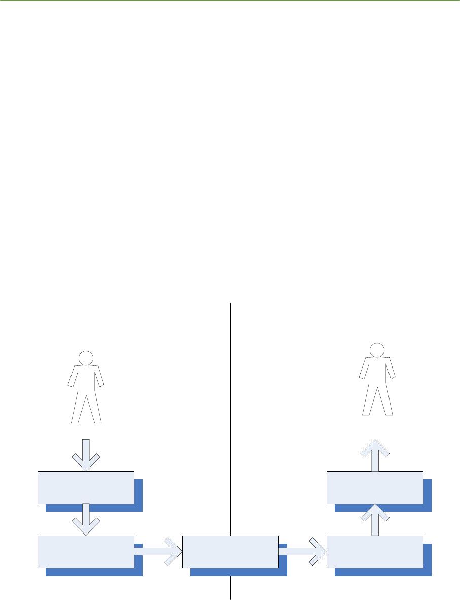
68 Location Software Library PLUS System Manual
Proprietary Information: Do not disclose unless authorized under a Nondisclosure Agreement and the Partner Agreement.
Maps can be used to provide a common coordinate system for all Readers that are part of the Map.
Maps are useful in multi-floor or multi-building installations. Maps must not overlap. To avoid this, a
Reader cannot be assigned to Groups in a way that allows the Reader to appear in more than one Map.
The Location Software supports limiting a Tag position to allowable regions, called Tracking Cells. The
Tracking Cell is defined by a set of points that form a polygon. Any Tag position outside the Tracking
Cell is discarded. Tracking cells can be defined for both Groups and Maps. Tracking Cells can also be
configured with a ―snap to‖ feature. If a Tag position is just outside the Tracking Cell, the ―snap to‖
feature allows the location software to move that position to the boundary of the Tracking Cell. For
example, if there is a walkway on the edge of the Tracking Cell, a Tag in this area could generate
positions just outside the Tracking Cell. With ―snap to‖ enabled, these positions are moved to the
nearest points on the Tracking Cell.
4.4 Location Software Configuration
The Tracker Object includes a complete API for configuring the operating parameters of the Location
Software. However, most applications do not need to use these capabilities. Instead, most installations
will use the PLUS Visualizer application to perform the initial system configuration. Once installation
is complete, Visualizer will generate a configuration file that contains all information necessary to
completely initialize the Location Software. All an application needs to do is perform a single Location
Software function call to tell the Tracker Object which file it will use to load its configuration
information.
V is u a liz e r
Location
E n g in e
C o n fig u ra tio n
F ile
U s e r
A p p lic a tio n
Location
E n g in e
S y s te m In s ta lla tio n S y s te m O p e r a tio n
U s e r
In s ta lle r
4.5 Location Software API
This section documents the components of the Location Software API in detail. Although the Tracker

PLUS System Manual Location Software Library 69
Proprietary Information: Do not disclose unless authorized under a Nondisclosure Agreement and the Partner Agreement.
Object includes a rich API for configuring and monitoring the Location Software, most applications
only need to use a few of the API features. Section 4.5.1 discusses the features of the API that are
commonly used by all applications. Section 4.5.2 discusses the more advanced features of the API,
including configuration and additional system monitoring features.
4.5.1 Commonly Used Functions
Most developers will only need to be familiar with the API features in this section. With these functions
and events, an application can initialize the Location Software, receive Tag positions from the Location
Software, and monitor the system for Reader alarm conditions. At startup, the typical application
registers a handler for the NewPosition event and calls the ReadConfig function to tell the Location
Software to load its initial configuration. Then the application calls StartTOAMessageQueue to begin
the processing of TOA messages from Readers. The application should also register a handler for the
TrackerAlarm event to monitor the system for Reader alarms. Each of these API features is discussed
in detail below.
4.5.1.1 ReadConfig Function
public virtual int ReadConfig( BSTR
filePath
)
Reads configuration file and processes configuration data. Previous configuration data in the tracker is deleted.
filePath
is the full path and name of configuration file.
Returns
0 – Success, entry added to list.
Less than zero - Failed to read and process configuration file, file may not exist
4.5.1.2 StartTOAMessageQueue Function
public virtual int StartTOAMessageQueue()
Starts the TOA packet/message queue.
Returns
0 – Success
Nonzero – Data source invalid/not set. If data source is an IP address, then the software could not bind a UDP
socket on port 11000 at that address. If data source is a file, then the software could not open the file to read it.
4.5.1.3 StopTOAMessageQueue Function
public virtual void StopTOAMessageQueue()
Stops the TOA packet/message queue.
70 Location Software Library PLUS System Manual
Proprietary Information: Do not disclose unless authorized under a Nondisclosure Agreement and the Partner Agreement.
4.5.1.4 IsTOAMessageQueueStarted Function
public virtual int IsTOAMessageQueueStarted()
Returns nonzero if the TOA message queue is started.
Returns
0 – TOA message queue not started
Nonzero – TOA message queue is started
4.5.1.5 NewPosition Event
public virtual void NewPosition( int
tagId
,
int
tagType,
int
positionType,
int
mapIndex,
float
x
,
float
y
,
float
z
,
int
timestamp,
int
batteryState,
,
int
buttonEvent
,
int
motion
,
int
bestReaderIdLow
,
int
bestReaderIdHi
,
int
postionFOM
,
int
seqNum
)
This event is fired whenever a Tag's position has been updated.
tagId
is the ID
of the Tag.
tagType
is the type: can be either tracking = 1 or calibration Tag = 2.
positionType
is the type of position.
0D = 1
1D = 2
2D = 3
mapIndex
is the index of the map.
x,y,z
are the computed position of the Tag.
motionFlag
,
buttonEvent
and
battery
are snapshots of those values from the Tag at the time the position was
calculated.
timestamp
is the time as returned by the Windows API function
GetTickCount()
at the time the Tag’s position was
calculated.
positionFom
is a figure of merit (quality metric) for the position. The range is 0 to 100, 0 being worst and 100
being best position metric. Currently,
positionFom
is always 100.

PLUS System Manual Location Software Library 71
Proprietary Information: Do not disclose unless authorized under a Nondisclosure Agreement and the Partner Agreement.
bestReaderIdLow, bestReaderIdHi
The best Reader is the first TOA of the last bundle used to produce a solution. It
is provided primarily as an aid in debugging.
4.5.1.6 TrackerAlarm Event
public virtual void TrackerAlarm( int
alarmType
int
alarmParm1,
int
alarmParm2,
int
alarmParm3,
int
alarmParm4
)
This event is fired for various alarm conditions: Reader alarm (a Reader sent a TOA packet with the alarm bit set),
Reader timeout (a Reader was not heard within a certain time span), and Tag timeout (a Tag was not heard within
a certain time span).
alarmType
Reader timeout =2
Reader alarm =3
Tag timeout = 4
Other alarm types may be defined in the future. Applications should ignore unknown alarms.
The alarm parameters vary depending on the type of alarm:
Reader Timeout:
alarmParm1 is the timestamp when the alarm occurred
alarmParm2 is the lower four bytes of the Reader MAC address that has timed out
alarmParm3 is the upper two bytes of the Reader MAC address that has timed out
alarmParm4 is unused
Reader alarm:
alarmParm1 is the timestamp when the alarm occurred
alarmParm2 is the lower portion of the Reader ID that has an alarm
alarmParm3 is the upper portion of the Reader ID that has an alarm
alarmParm4 is unused
Tag timeout:
alarmParm1 is the timestamp when the alarm occurred
alarmParm2 is the Tag ID that has timed out
alarmParm3 is unused
alarmParm4 is unused
4.5.2 Advanced API Features
This section describes the advanced features of the Location Software API. These features are not used
by most applications. However, they are discussed here for completeness.
4.5.2.1 Alarms
The Location Software can send alarm events as an aid in monitoring system health and status. Three
types of alarms are: Reader timeout, Reader Alarm, and Tag timeout. A Reader timeout alarm is fired
when the Location Software has received no data (neither TOA nor discovery packets) from a Reader in
a configurable amount of time. A Reader alarm is fired when a TOA packet with the alarm bit set is

72 Location Software Library PLUS System Manual
Proprietary Information: Do not disclose unless authorized under a Nondisclosure Agreement and the Partner Agreement.
received from a Reader. Once a Reader alarm event has fired, the Location Software will wait a
configurable amount of time before sending another Reader alarm event. A Tag timeout alarm is fired
when the Location Software has not received a Tag transmission in a configurable amount of time.
4.5.2.1.1 SetTrackerAlarmTimeout Function
public virtual int SetTrackerAlarmTimeout( int
alarmType,
,
int
alarmTimeoutValue
)
This function sets alarm timeouts.
alarmType
is the alarm that the timeout controls.
Reader Timeout = 2
Reader Alarm = 3
Tag Timeout = 4
alarmTimeoutValue
is the timeout value. The units are in seconds. Its meaning depends on
alarmType
:
Reader Timeout - a Reader has not been heard within
alarmTimeoutValue
seconds.
Reader Alarm – once a Reader alarm has fired, it will not refire within
alarmTimeoutValue
seconds.
Tag Timeout - a Tag has not been heard within
alarmTimeoutValue
seconds.
The default value for all alarm types is 10 seconds.
For all alarm types, a timeout value of 0 will disable alarms of that type.
Returns
0 – Success,
Less than zero – either invalid alarm type or timeout value is out of range.
4.5.2.1.2 GetTrackerAlarmTimeout Function
public virtual int GetTrackerAlarmTimeout( int
alarmType,
,
int
out alarmTimeoutValue
)
This function retrieves the timeout value for a specific alarm.
alarmType
is the alarm that the timeout controls.
Reader Timeout = 2
Reader Alarm = 3
Tag Timeout = 4
alarmTimeoutValue
is the timeout value. The units are in seconds. Its meaning depends on
alarmType
:
Reader Timeout - a Reader has not been heard within
alarmTimeoutValue
seconds.
Reader Alarm – once a Reader alarm has fired, it will not refire within
alarmTimeoutValue
seconds.
Tag Timeout - a Tag has not been heard within
alarmTimeoutValue
seconds.
Returns
0 – Success,
Less than zero –invalid alarm type.
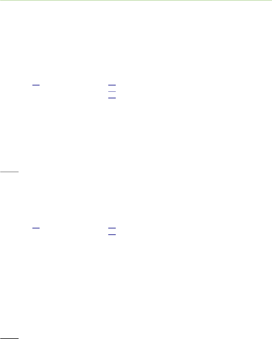
PLUS System Manual Location Software Library 73
Proprietary Information: Do not disclose unless authorized under a Nondisclosure Agreement and the Partner Agreement.
4.5.2.2 Calibration
These functions, properties and events are used to control calibration of a Group.
4.5.2.2.1 ControlAutoCal Function
public virtual int ControlAutoCal( int
groupId,
int
calPeriod
,
int
calFlags)
Starts auto calibration on a group. The function can also be used to cancel a calibration in progress.
groupId
is the ID for the group.
calPeriod
is the calibration period in seconds
calFlags 0 start calibration
1 cancel calibration
Returns
0 - Success
Less than zero - Invalid group ID or parameter
4.5.2.2.2 GetAutoCalStatus Function
public virtual int GetAutoCalStatus( int
groupId,
int
currentAutoCalStatus)
This function retrieves the current auto calibration state for a group. A calibration can be in progress, or a
calibration can have completed successfully, or completed and failed.
groupId
is the ID for the group.
currentAutoCalStatus
is the current auto calibration state of the group.
0 = calibration state unknown, may never have calibrated this group
1 = calibration in progress
2 = calibration successful
3 = calibration failed.
Returns
0 - Success
Less than zero - Invalid group ID or parameter

74 Location Software Library PLUS System Manual
Proprietary Information: Do not disclose unless authorized under a Nondisclosure Agreement and the Partner Agreement.
4.5.2.2.3 GetAutoCalGroupEntryInfo Function
public virtual int GetAutoCalGroupEntryInfo( int r
eaderIdLow
,
int r
eaderIdHigh,
int
groupId,
double out
readerGroupCalValue,
int out calReaderGroupStatus
)
This function retrieves the current auto calibration data for a group entry. A calibration can be in progress, or a
calibration can have completed successfully, or completed and failed.
groupId
is the ID for the group.
readerIdLow
is the lower portion of Reader ID.
readerIdHi
is the upper portion of Reader ID.
readerGroupCalValue
is the TOA correction factor that is added to each TOA received for this Reader in this group.
calReaderGroupStatus
is the current auto calibration state of the Reader in this group.
0 = calibration state unknown, may never have calibrated this Reader
1 = calibration in progress
2 = calibration successful
3 = calibration failed.
Returns
0 - Success
Less than zero - Invalid group ID or Reader ID
4.5.2.2.4 AddCalIncludeExcludeEntry Function
public virtual int AddCalIncludeExcludeEntry( int
readerIdLow
,
int
readerIdHigh
,
int
tagId
)
Adds an entry to calibration include/exclude list. This entry is a Reader/calibration Tag pair. The
calIncludeExcludeFlag
property controls whether entries are included in calibration or excluded from calibration,
and should be set prior to calling this funciton. Setting that property also resets the include/exclude list and deletes
all the entries in the list.
tagId
is the ID
of calibration Tag.
readerIdLow
is the lower four bytes of the Reader MAC address.
readerIdHi
is the upper two bytes of the Reader MAC address.
Returns
0 – Success, entry added to list.
Less than zero - Failed to add entry to list.

PLUS System Manual Location Software Library 75
Proprietary Information: Do not disclose unless authorized under a Nondisclosure Agreement and the Partner Agreement.
4.5.2.2.5 GetNextCalIncludeExcludeEntry Function
public virtual int GetNextCalIncludeExcludeEntry( int
readerIdLow
,
int
readerIdHigh
,
int
tagId
,
int out
nextReaderIdLow
,
int out
nextReaderIdHigh
,
int out
nextTagId
)
Retrieves the next calibration include/exclude entry in the list. To get the first entry in the list, pass 0 in for the
readerIdLow, readerIdHi,
and
tagId
parameters
.
readerIdLow
is the lower portion of Reader ID.
readerIdHi
is the upper portion of ID.
tagId
is the ID of calibration Tag.
nextReaderIdLow
is the lower portion of Reader ID.
nextReaderIdHi
is the upper portion of Reader ID.
nextTagId
is the ID of the calibration Tag.
Returns
0 – Success, entry was retrieved.
Less than zero - Failed to find next entry in list.
4.5.2.2.6 calIncludeExcludeFlag Property
public virtual int
calIncludeExcludeFlag
{ set; get; }
Indicates whether entries in the calibration include/exclude list should be included in calibration or excluded from
calibration. When set to zero (0), the default value, the entries in the list are excluded. When set to a one (1), the
entries in the list are included. Setting this property will reset the include/exclude list (i.e., it will delete all entries
in the list). Therefore, it should be set prior to populating the list with the AddCalIncludeExcludeEntry function.
4.5.2.2.7 AutoCalGroupComplete Event
public virtual void AutoCalGroupComplete( int
groupId,
int
state)
This event is fired when an auto calibration for a group finishes. The state indicates if the calibration was
successful for the group. A successful calibration means that a calibration value for each enabled Reader was
computed.

76 Location Software Library PLUS System Manual
Proprietary Information: Do not disclose unless authorized under a Nondisclosure Agreement and the Partner Agreement.
state
0 = calibration state unknown, may never have run a calibration this group
1 = calibration in progress
2 = calibration successful
3 = calibration failed.
4.5.2.3 Configuration Storage
This function is used to store the configuration of the Location Software to a file. The counterpart to
this function, ReadConfig, was discussed previously in the Commonly Used Functions section.
4.5.2.3.1 WriteConfig Function
public virtual int WriteConfig( BSTR
filePath
)
Write current configuration data to a configuration file.
filePath
this is the full path and name of configuration file.
Returns
0 – Success
Less than zero - Failed to write configuration file
4.5.2.4 Group Configuration
The functions in this section are used to configure the Location Software’s internal database of Reader
Groups.
4.5.2.4.1 AddOrUpdateGroup Function
public virtual int AddOrUpdateGroup( int
groupId
,
int
groupState,
int
groupFlags,
int
allowedSolverFlags,
int
mapIndex,
double *
trackingCellPoints,
int
trackingCellPointsBufferSize,
double
trackingCellSnap)
Adds a Group to the tracker's Group database. If the Group already exists, updates the Groups's configuration.
groupId
is the ID for the group. Group ID should greater than or equal to zero. Do not use –1 as a group Id
because that value is used to denote all groups in other interface functions.
groupState
denotes that the group is enabled or disabled
0 - group disabled

PLUS System Manual Location Software Library 77
Proprietary Information: Do not disclose unless authorized under a Nondisclosure Agreement and the Partner Agreement.
1 - group enabled.
groupFlags
is a bit field that controls group characteristics
Bit 0 - Group Tracking Cell is enabled
Bit 3 - Co-linearity check disabled.
Bit 4 - Group can be calibrated – currently this bit is ignored.
Bit 5 - RSSI Sorting, used for groups that only provide 0D or presence detect positions and the Readers
in that group are not synchronized
allowedSolverFlags
is a bit field that controls which type of solutions a group can produce.
Bit 0 - 0D or Presence Detect
Bit 1 - 1D
Bit 2 - 2D
mapIndex
associates this group to a map.
trackingCellPoints
is a buffer containing the points that define a tracking cell. Each point in the tracking cell is
defined by two values in the buffer (x and y).
trackingCellPointsBufferSize
is the number of values in the tracking cell. Each point requires two values, an X and Y
value. For example if four points define a tracking cell then the buffer would contain eight values.
trackingCellSnap
is used to control the “snap to” feature. If a position is outside the tracking cell, the distance to
the nearest point on the tracking cell boundary is computed. If that distance is less than this value, the position is
replaced with the nearest point on the tracking cell boundary. If the computed distance is larger that this value,
the position is discarded.
Returns
0 - Success
Less than zero - Invalid group parameter
4.5.2.4.2 GetGroup Function
public virtual int GetGroup( int
groupId
,
int out
groupState,
int out
groupFlags,
int out
allowedSolverFlags,
int out
mapIndex,
double out *
trackingCellPoints,
int
trackingCellPointsBufferSize,
int out
trackingCellPointsBufferUsed,
double out
trackingCellSnap)
Retrieves information about a Group from the tracker's Group database. The Group must exist or an error is
returned.
groupId
is the ID for the group. Group ID should be greater than or equal to zero. Do not use –1 as a group Id
because that value is used to denote all groups in other interface functions.
groupState
denotes that the group is enabled or disabled
0 - group disabled
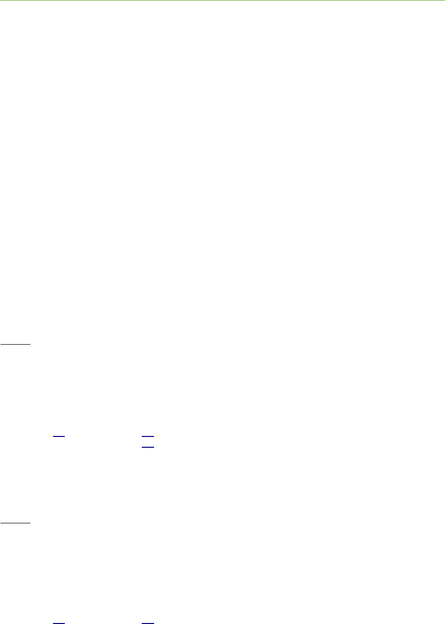
78 Location Software Library PLUS System Manual
Proprietary Information: Do not disclose unless authorized under a Nondisclosure Agreement and the Partner Agreement.
1 - group enabled.
groupFlags
is a bit field that controls group characteristics
Bit 0 - Group Tracking Cell is enabled
Bit 3 - Co-linearity check disabled.
Bit 4 - Group can be calibrated – currently this bit is ignored.
Bit 5 - RSSI Sorting, used for groups that only provide 0D or presence detect positions and the Readers
in that group are not synchronized
allowedSolverFlags
is a bit field that controls which type of solutions a group can produce.
Bit 0 - 0D or Presence Detect
Bit 1 - 1D
Bit 2 - 2D
mapIndex
associates this group to a map.
trackingCellPoints
is a buffer containing the points that define a tracking cell. Each point in the tracking cell is
defined by two values in the buffer (x and y).
trackingCellPointsBufferSize
is the number of values in the tracking cell. Each point requires two value,s an X and Y
value. For example if four points define a tracking cell then the buffer would contain eight values.
trackingCellSnap
is used to control the “snap to” feature. If a position is outside the tracking cell, the distance to
the nearest point on the tracking cell boundary is computed. If that distance is less than this value, the position is
replaced with the nearest point on the tracking cell boundary. If the computed distance is larger that this value,
the position is discarded.
Returns
0 - Success
Less than zero - Invalid group ID
4.5.2.4.3 GetNextGroup Function
public virtual int GetNextGroup( int
currentGroupId
,
int out
nextGroupId
)
Retrieves next group ID given a group ID. The next group ID is the next higher number group. To retrieve the first
group ID, pass -1 in the
currentGroupId
parameter.
Returns
0 - Success
Less than zero – No group ID higher than currentGroupId (currentGroupId is the last group).
4.5.2.4.4 RemoveGroup Function
public virtual int RemoveGroup( int
groupId)
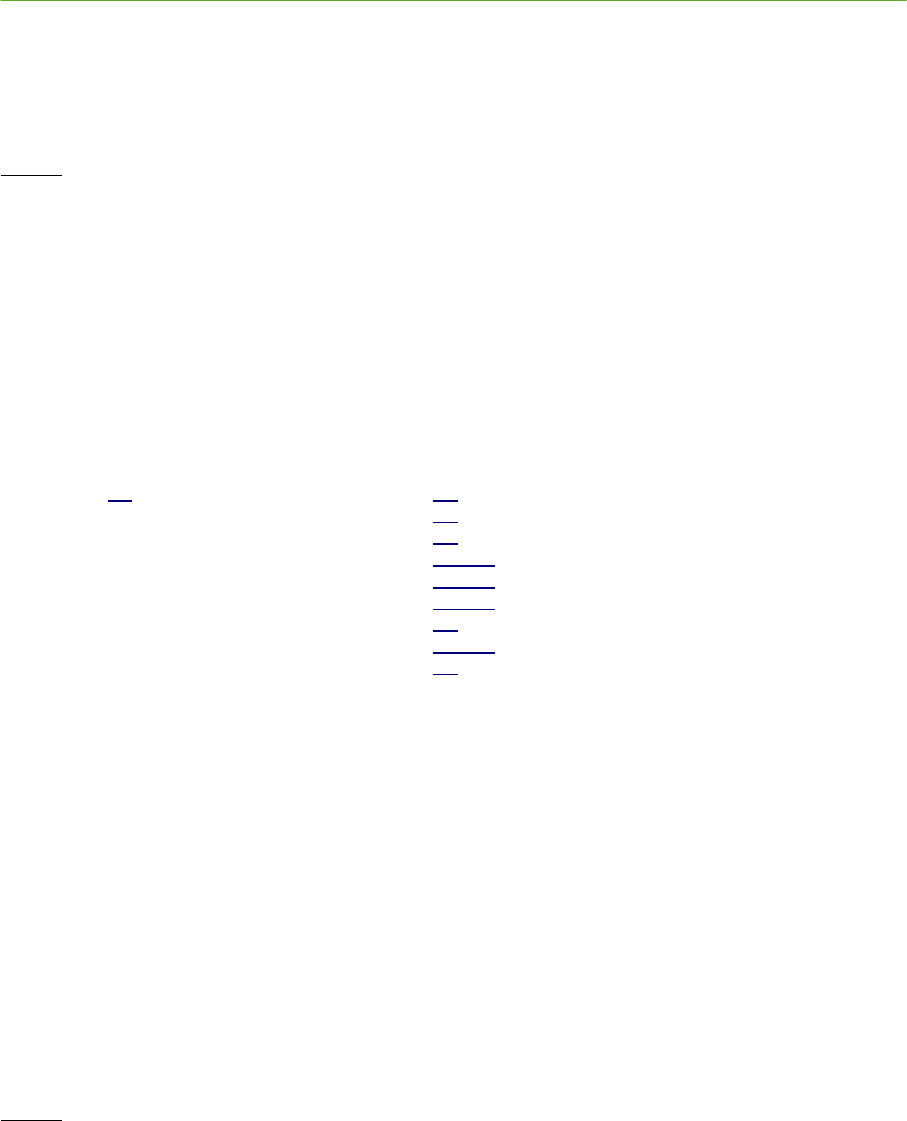
PLUS System Manual Location Software Library 79
Proprietary Information: Do not disclose unless authorized under a Nondisclosure Agreement and the Partner Agreement.
Removes a group from the tracker's database. The group must exist or an error is returned. Group 0 cannot be
deleted. It is created at startup to handle old configuration files and Readers not in the current configuration.
groupId
is the ID for the group.
Returns
0 - Success
Less than zero - Invalid group ID
4.5.2.5 Group Entry Configuration
The functions in this section are used to add, remove, and configure Reader entries within the Groups.
4.5.2.5.1 AddOrUpdateGroupEntry Function
public virtual int AddOrUpdateGroupEntry( int
readerIdLow
,
int
readerIdHigh
,
int
groupId,
double
x
,
double
y
,
double
z
,
int
readerState,
double
calibrationValue,
int
calibrationValid,
)
This function adds a Reader entry to a group in the tracker's database. If the Reader entry already exists, it
updates the configuration.
readerIdLow
is the lower four bytes of the Reader MAC address.
readerIdHigh
is the upper two bytes of the Reader MAC address.
groupId
is the ID for the group
x,y,z
is the location of the Reader, units are meters.
readerState
indicates whether the Reader is enabled for this group. A Reader can be enabled in one group and
disabled in another group.
calibrationValue
is the TOA correction factor that is added to each TOA received for this Reader in this group. The
same Reader in another group can have a different calibration value.
calibrationValid
is a flag indicating that
calibrationValue
is valid. If a Reader has been calibrated, the calibration
constant should be passed in
calibrationValue
and
calibrationValid
should be set to TRUE. If a Reader has not been
calibrated, then
calibrationValid
should be set to FALSE and the Location Software will ignore
calibrationValue
.
Returns
0 - Success
less than zero - Invalid group ID or invalid parameters.
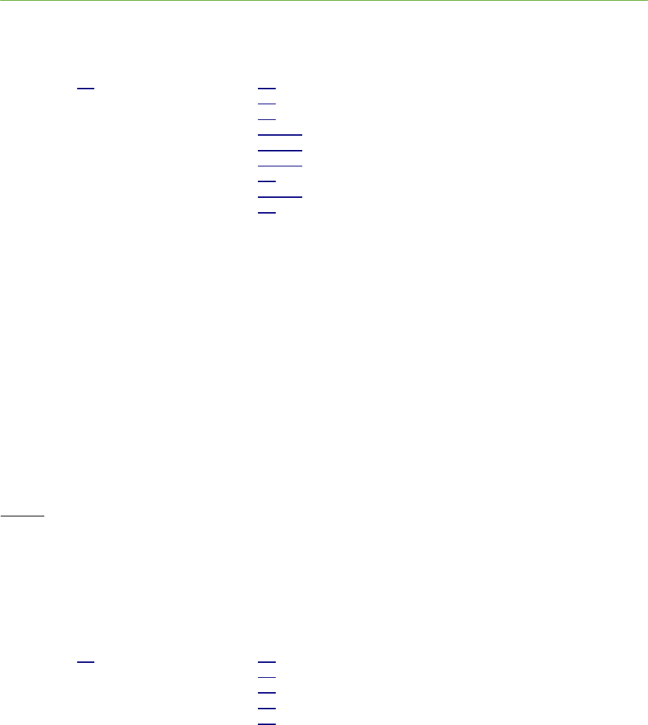
80 Location Software Library PLUS System Manual
Proprietary Information: Do not disclose unless authorized under a Nondisclosure Agreement and the Partner Agreement.
4.5.2.5.2 GetGroupEntry Function
public virtual int GetGroupEntry( int
readerIdLow
,
int
readerIdHigh
,
int
groupId,
double out
x
,
double out
y
,
double out
z
,
int out
readerState,
double out
calibrationValue,
int out
calibrationValid,
)
This function retrieves a Reader entry from a group. The Reader entry must already exist or an error is returned.
readerIdLow
is the lower four bytes of the Reader MAC address of the requested Reader entry.
readerIdHigh
is the upper two bytes of the Reader MAC address of the requested Reader entry.
groupId
is the ID for the group of the requested Reader entry.
x,y,z
is the location of the Reader, units are meters.
readerState
indicates whether the Reader is enabled for this group. A Reader can be enabled in one group and
disabled in another group.
calibrationValue
is the TOA correction factor that is added to each TOA received for this Reader in this group. The
same Reader in another group can have a different Calibration value.
calibrationValid
is a flag indicating that
calibrationValue
is valid. If a Reader has been calibrated, the calibration
constant should be passed in
calibrationValue
and
calibrationValid
should be set to TRUE. If a Reader has not been
calibrated, then
calibrationValid
should be set to FALSE and the Location Software will ignore
calibrationValue
.
Returns
0 - Success
less than zero – Reader entry does not exist.
4.5.2.5.3 GetNextGroupEntry Function
public virtual int GetNextGroupEntry( int
groupId
,
int
currentReaderIdLow
,
int
currentReaderIdHigh
,
int
nextReaderIdLow
,
int
nextReaderIdHigh
)
Retrieves the next Reader in a group given a Reader MAC address. The next Reader MAC address is the next
higher value. To get the first Reader in the group, pass 0 in the
currentReaderIdLow
and
currentReaderIdHigh
parameters.
groupId
is the ID of the group containing the Readers.
currentReaderIdLow
is the lower four bytes of the current Reader MAC address.
currentReaderIdHi
is the upper two bytes of the current Reader MAC address.
nextReaderIdLow
is the lower four bytes of the next Reader MAC address.
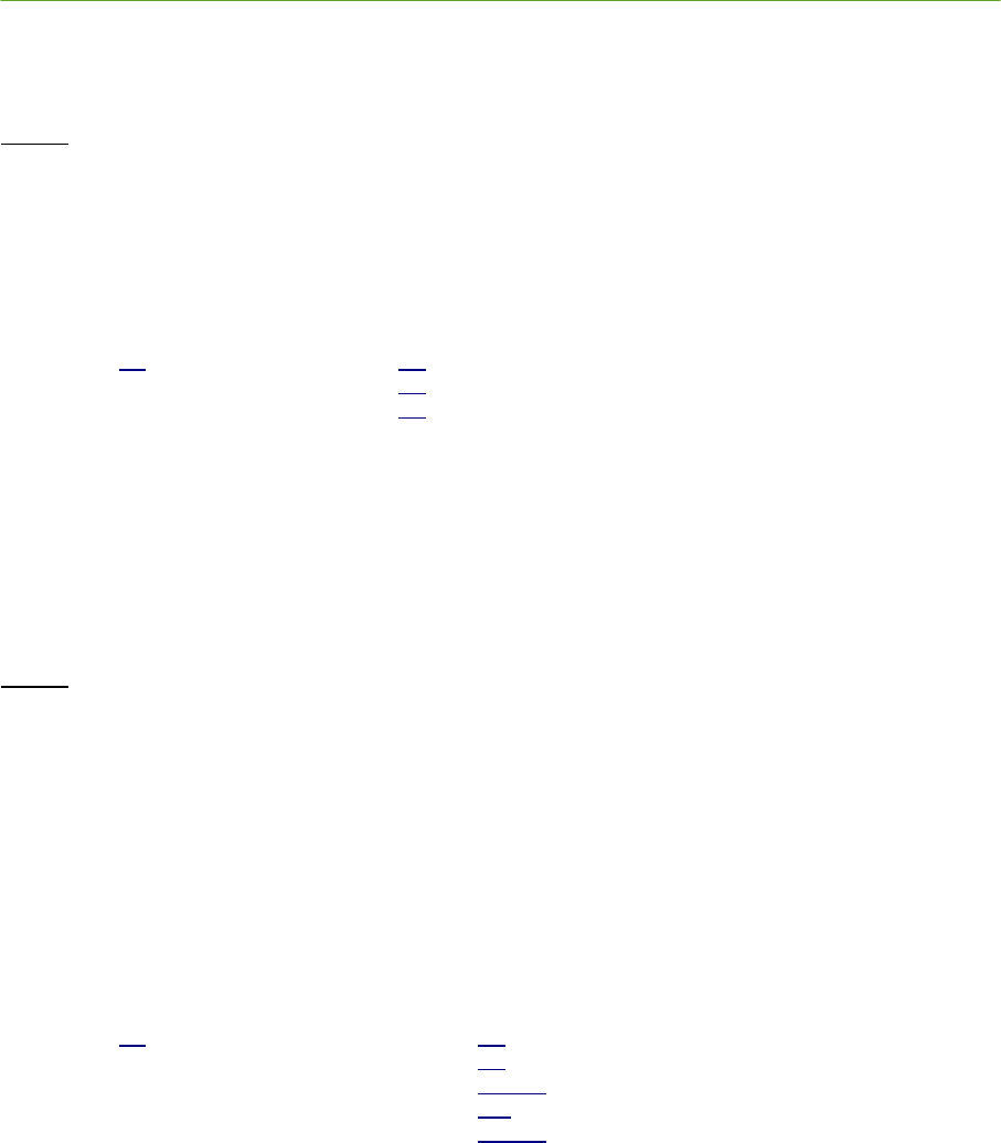
PLUS System Manual Location Software Library 81
Proprietary Information: Do not disclose unless authorized under a Nondisclosure Agreement and the Partner Agreement.
nextReaderIdHi
is the upper two bytes of the next Reader MAC address.
Returns
0 - Success
Less than zero – No Reader higher than current Reader (current Reader is the last Reader in the group).
4.5.2.5.4 RemoveGroupEntry Function
public virtual int RemoveGroupEntry( int
groupId,
int
readerIdLow
,
int
readerIdHigh)
This function removes a Reader from a group. The Reader entry must exist or an error is returned.
groupId
is the ID for the group.
readerIdLow
lower four bytes of the Reader MAC address.
readerIdHi
upper two bytes of the Reader MAC address.
Returns
0 - Success
Less than zero - Invalid group ID or Reader MAC address
4.5.2.6 Map Configuration
These functions allow configuration of the Location Software’s internal database of Maps.
4.5.2.6.1 AddOrUpdateMapParms Function
public virtual int AddOrUpdateMapParms( int
mapIndex,
int
flags,
double
snapDist,
int
bufferSize,
double *
trackingCellPoints)
This function sets the parameters for a map. A map can have a tracking cell which is a polygon boundary limiting
where Tag positions can be computed. If the map parameters already exist, they are updated.
mapIndex
is the ID for the map. Must be greater or equal to zero.
flags
is a bit field that controls the group characteristics
Bit 0 - Map Tracking Cell is enabled
snapDist
is used to control the “snap to” feature. If a position is outside the tracking cell, the distance to the
nearest point on the tracking cell boundary is computed. If that distance is less than this value, the position is
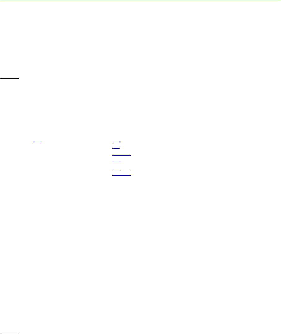
82 Location Software Library PLUS System Manual
Proprietary Information: Do not disclose unless authorized under a Nondisclosure Agreement and the Partner Agreement.
replaced with the nearest point on the tracking cell boundary. If the computed distance is larger that this value,
the position is discarded.
bufferSize
is the number of values in the tracking cell. Each point requires two values, an X and Y value. For
example if four points define a tracking cell then the buffer would contain eight values.
trackingCellPoints
is a buffer containing the points that define a tracking cell. Each point is the x,y position of that
point.
Returns
0 - Success
less than zero – Invalid map parameters.
4.5.2.6.2 GetMapParms Function
public virtual int GetMapParms( int
mapIndex,
int out
flags,
double out
snapDist
,
int
bufferSize,
int out
bufferUsed,
double *
trackingCellPoints)
This function retrieves the parameters for a map. A map can have a tracking cell which is a polygon boundary
limiting where Tag positions can be computed. The map must exist or an error is returned.
mapIndex
is the ID for the map. Must be greater or equal to zero.
flags
is a bit field that controls the map characteristics
Bit 0 - Map Tracking Cell is enabled
snapDist
is used to control the “snap to” feature. If a position is outside the tracking cell, the distance to the
nearest point on the tracking cell boundary is computed. If that distance is less than this value, the position is
replaced with the nearest point on the tracking cell boundary. If the computed distance is larger that this value,
the position is discarded.
bufferSize
is the number of values in the tracking cell. Each point requires two values, an X and Y value. For
example if four points define a tracking cell then the buffer would contain eight values.
trackingCellPoints
is a buffer containing the points that define a tracking cell. Each point is the x,y position of that
point.
Returns
0 - Success
less than zero – Invalid mapIndex.
4.5.2.7 Calibration Tag Configuration
The functions in this section are used to configure the Location Software’s internal database of
calibration Tags.

PLUS System Manual Location Software Library 83
Proprietary Information: Do not disclose unless authorized under a Nondisclosure Agreement and the Partner Agreement.
4.5.2.7.1 AddOrUpdateCalTag Function
public virtual int AddOrUpdateCalTag( int
tagId,
double
x,
double
y,
double
z,
int
*groupIdList,
int
groupIdListLength
)
This function adds a calibration Tag to the tracker's Calibration Tag database. If the Tag already exists, it updates
the Tag's configuration. Calibration Tags are necessary for calibrating the Readers. They are always at fixed
positions specified by
X
,
Y
, and
Z
.
tagId
is the ID of Tag.
x,y,z is the position of Tag.
groupIdList
is not implemented.
groupIdListLength
is not implemented
Returns
0 - Success
Less than zero- Invalid value for
x,y
or
z
(Invalid values are NaN’s)
4.5.2.7.2 GetCalTag Function
public virtual int GetCalTag( int
tagId,
double out
x,
double out
y,
double out
z,
int
out
*groupIdList,
int
out
groupIdListLength
)
Retrieves a Calibration Tag's configuration.
tagId
is the ID of Tag.
x,y,z
is the position of Tag.
groupIdList
is not implemented.
groupIdListLength
is not implemented.

84 Location Software Library PLUS System Manual
Proprietary Information: Do not disclose unless authorized under a Nondisclosure Agreement and the Partner Agreement.
Returns
0 - Success; the Tag exists and the
x, y
and
z
coordinates have been returned.
Less than zero - The Calibration Tag does not exist in the database.
4.5.2.8 Tag Configuration
The functions in this section are used to configure the Location Software’s internal Tag database.
4.5.2.8.1 AddOrUpdateTag Function
public virtual int AddOrUpdateTag( int
tagId
,
double
nominalZheight
)
Adds a Tag (non-Calibration Tag) to the Tag database. If the Tag already exists, it updates the Tag's
configuration. Since the location engine can only track Tags on 2D planes, the Tag's nominal Z height must be
configured beforehand in the
nominalZheight
parameter. Setting the nominalZHeight is only needed when the Tag
is at a different height than the system default nominalZHeight.
tagId
is the ID of Tag.
nominalZheight
is the height above floor of the Tag.
Returns
0 - Success
less than zero - Invalid value for
nominalZheight
(Invalid values are NaN’s)
4.5.2.8.2 GetTag Function
public virtual int GetTag( int
tagId
,
double out
nominalZheight
)
Retrieves a Tag’s
nominalZHeight
from the Tag database. The Tag must exist or an error is returned.
tagId
is the ID of Tag.
nominalZheight
is the height above floor of the Tag.
Returns
0 - Success
less than zero – Tag does not exist or invalid value for
nominalZheight
(Invalid values are NaNs)
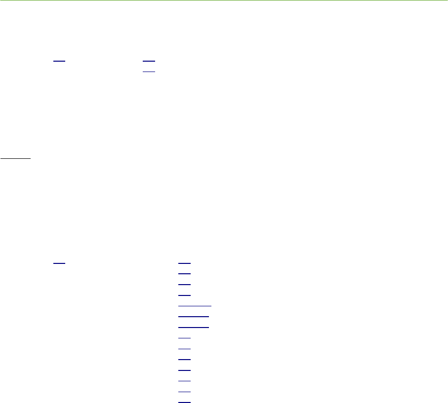
PLUS System Manual Location Software Library 85
Proprietary Information: Do not disclose unless authorized under a Nondisclosure Agreement and the Partner Agreement.
4.5.2.8.3 GetNextTag Function
public virtual int GetNextTag( int
currentTagId
,
int out
nextTagId
)
Retrieves next Tag ID given a Tag ID. The next Tag ID is the next higher numbered Tag. To retrieve the first
(lowest numbered) Tag ID, pass -1 in the
currentTagId
parameter.
Returns
0 - Success
Less than zero – No Tag ID higher than currentTagId (currentTagId is the last Tag ID).
4.5.2.8.4 GetTagPosition Function
public virtual int GetTagPosition( int
tagId
,
int out
tagType
,
int out
positionType,
int
out mapIndex
,
double out
x
,
double out
y
,
double out
z
,
int out
timestamp,
int out
batteryState,
int out
buttonEvent,
int out
motion
,
int out
bestReaderIdLow,
int out
bestReaderIdHi
,
int out
positionFom
)
Retrieves information on the last position calculated for the specified Tag. If a Tag’s position has not been
calculated, this function returns a nonzero value and does not return any Tag information.
tagId
is the ID of the Tag.
tagType
is the type. It can be either tracking = 1 or calibration Tag = 2.
positionType
is the type of position.
0D = 1
1D = 2
2D = 3
mapIndex
is the index of the map
x,y,z
are the computed coordinates of the Tag.
motionFlag
,
buttonEvent
and
battery
are snapshots of those values from the Tag at the time the position was
calculated.
timestamp
is the time as returned by the Windows API function
GetTickCount()
at the time the Tag’s position was

86 Location Software Library PLUS System Manual
Proprietary Information: Do not disclose unless authorized under a Nondisclosure Agreement and the Partner Agreement.
calculated.
bestReaderIdLow, bestReaderIdHi
The best Reader is the first TOA of the last bundle used to solve. This is include
primarily as a debugging aid.
positionFom
is a figure of merit (quality metric) for the position. The range is 0 to 100, 0 being worst and 100
being best position metric.
Returns
0 – Success
Less then zero – Unknown Tag ID or No solution available
4.5.2.8.5 RemoveTag Function
public virtual int RemoveTag( int
tagId
)
Removes a Tag from the Tag database. The Tag can be either a normal Tag or a calibration Tag.
tagId
is the ID of the Tag.
Returns
0 – Success
Less than zero – Unknown Tag ID
4.5.2.9 Solver Configuration
The Location Software Solver has a number of parameters that are user-configurable, such as filter
settings. The functions in this section are used to get and set those parameters.
4.5.2.9.1 SetSolverParm Function
public virtual int SetSolverParm( int
parameterId,
variant
parameter
)
Sets one of the allowable solver parameters. Parameters can be different types; some are integer and some are
floating point values. A Variant structure is used to deliver the parameter.
The following table describes the currently documented solver parameters:
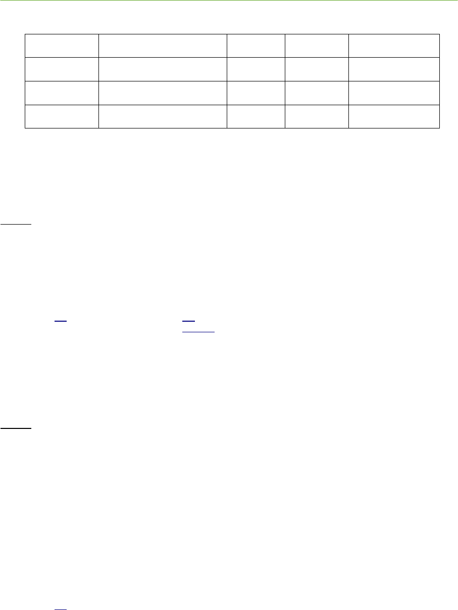
PLUS System Manual Location Software Library 87
Proprietary Information: Do not disclose unless authorized under a Nondisclosure Agreement and the Partner Agreement.
Parameter ID
Description
Type
Units
Default Value
2
Nominal Tag Z height
double
m
1
8
Moving average filter depth
integer
N/A
3
9
Tag speed limit filter
double
m/s
2
The nominal Tag Z height is the default Tag height assumed by the solver. This value can be overridden on a per-
Tag basis with the AddOrUpdateTag function.
The Tag speed limit filter and moving average filter can be disabled by setting them to a value of 0.
Returns
0 – Success
Less than zero – Unknown Parameter ID or invalid parmeter
4.5.2.9.2 GetSolverParms Function
public virtual int GetSolverParm( int
parameterId,
variant
out parameter
)
Retrieve one of the allowable solver parameters. Parameters can be different types; some are integer and some
are floating point values. A Variant structure is used to retrieve the parameter.
Documented solver parameters are described in the previous paragraph.
Returns
0 – Success
Less than zero – Unknown Parameter ID or invalid parameter
4.5.2.10 Data Source Configuration
Normally, the Location Software gets its TOA data from a network interface. Optionally, this TOA data
can be read from a raw log file. The functions and properties in this section allow the TOA data source
to be configured.
4.5.2.10.1 IsDataSourceIPAddr Function
public virtual int IsDataSourceIPAddr()
This function returns zero if DataSource is empty or is not a valid IP address; it returns nonzero if it is a valid IP
address in string form.
88 Location Software Library PLUS System Manual
Proprietary Information: Do not disclose unless authorized under a Nondisclosure Agreement and the Partner Agreement.
Returns
0 – Data source is not a valid IP address
Nonzero – Data source is an IP address
4.5.2.10.2 SetInput Function
public virtual int SetInput( int
input
)
Selects either raw file or live data (IP data) as input to tracker
input
1 = IP Data – Live data from Ethernet interface.
0 = Replay data from a raw file.
Returns
0 – Success.
Less that zero - Failed
4.5.2.10.3 GetInput Function
public virtual int GetInput()
This function returns an indication of whether the system is using live data or data from a raw file.
Returns
1 = IP Data – Live data from Ethernet interface.
0 = Replay data from a raw file.
4.5.2.10.4 IsRawFileFinished Function
public virtual int IsRawFileFinished()
This function returns an indication of whether the system has finished processing all the data in the raw file.
Returns
1 - raw file finished.
0 - raw file still playing

PLUS System Manual Location Software Library 89
Proprietary Information: Do not disclose unless authorized under a Nondisclosure Agreement and the Partner Agreement.
4.5.2.10.5 playbackMode Property
public virtual int playbackMode { set; get; }
This function sets the playback options for raw log files. Has no effect on live data streaming. The
playbackMode must be set before StartTOAMessageQueue is called.
Bit 0 – if set, playback is not paced by the timestamp recorded for each logged TOA message, i.e. the file is played
back at maximum speed. However, the timestamp is still passed to the solver for determining Tag speed. Default
is 0.
Bit 1 – if set, loops playback of the logfile. Default is 0.
Values for playbackMode
0 – Default behavior, logfile is processed at normal speed and stops when the end is reached.
1 – Logfile is processed at maximum speed and stops when the end is reached.
2 – Logfile is processed at normal speed and starts over when the end is reached.
3 – Logfile is processed at maximum speed and starts over when the end is reached.
4.5.2.10.6 inputRawFileName Property
public virtual string inputRawFileName { set; get; }
Specifies input file name of saved TOA messages. This property must be set before StartTOAMessageQueue is
called.
4.5.2.10.7 localIpInterface Property
public virtual string localIpInterface { set; get; }
Specifies which local IP interface to use to get TOA messages. The default is “0.0.0.0”, meaning any available
network interface. This property must be set before StartTOAMessageQueue is called.

90 Location Software Library PLUS System Manual
Proprietary Information: Do not disclose unless authorized under a Nondisclosure Agreement and the Partner Agreement.
4.5.2.11 Debug and Troubleshooting
The functions, properties, and events in this section may be useful in troubleshooting installation
problems. In particular, the outputLogFileName property controls logging of raw TOA data to a file.
4.5.2.11.1 outputLogFileName Property
public virtual string outputLogFileName { set; get; }
If empty, no data is logged. If a filename is specified, TOA messages are saved to that file. This property must be
set before StartTOAMessageQueue is called.
4.5.2.11.2 minTagId Property
public virtual int minTagId { set; get; }
Input Tag filtering. Sets the lower limit on which Tags will accepted by the system.
4.5.2.11.3 maxTagId Property
public virtual int maxTagId { set; get; }
Input Tag filtering. Sets the upper limit on which Tags will accepted by the system.
4.5.2.11.4 NewTOAMessage Event
public virtual void NewTOAMessage( int
readerIdLow
,
int
readerIdHi
,
int
version,
int
batteryState,
,
int
buttonEvent
,
int
seqNum
,
int
motion
,
int
alarm
,
int
tagId,
int
coarseTOA,
int
fineTOA,
int
rssi,
int
preambleCount,
int
invalidTOA,
int
ipAddr,
int
timestamp)
PLUS System Manual Location Software Library 91
Proprietary Information: Do not disclose unless authorized under a Nondisclosure Agreement and the Partner Agreement.
This event is fired whenever a new TOA message is received.
Timestamp
is the time as returned by the Windows
API function
GetTickCount()
at the time the TOA is received.
4.5.2.12 Miscellaneous
Miscellaneous functions include a convenient way to send commands to a Reader and a routine to flush
the TOA message queue.
4.5.2.12.1 FlushTOAMessageQueue Function
public virtual void FlushTOAMessageQueue()
Removes all pending TOA messages in the queue. This should be called when changing data sources after the
TOA message queue has been stopped.
4.5.2.12.2 SendReaderCommand Function
public virtual BSTR SendReaderCommand( int
ipAddr,
BSTR
command
int
timeout,
int
numResponseStrs
)
Sends a command to a Reader and returns the response.
Returns
Response String
4.5.2.13 Status Monitoring
The events in this section allow an application to be notified of changes occurring within the Location
Software.
4.5.2.13.1 NewReader Event
public virtual void NewReader( int
readerIdLow
,
int
readerIdHi
,
int
state,
int
discoveryMethod)
This event is fired whenever a TOA message for a Reader not is in the database is received. This event also fires
when the configuration information for a Reader is read from a configuration file.
92 Location Software Library PLUS System Manual
Proprietary Information: Do not disclose unless authorized under a Nondisclosure Agreement and the Partner Agreement.
4.5.2.13.2 NewTag Event
public virtual void NewTag( int
tagId,
int
readerIdLow
,
int
readerIdHi
,
int
seqNum)
This event is fired whenever a new Tag is detected.
4.5.2.13.3 NewGroupEntry Event
public virtual void NewGroupEntry( int
readerIdLow
,
int
readerIdHi
,
int
groupId,
int
state)
This event is fired whenever a Reader entry is added to a group. The event can be fired when Reader information
is read from configuration file or when the application calls AddOrUpdateReaderGroupEntry.
4.5.2.13.4 NewCalTag Event
public virtual void NewCalTag( int
tagId,
float
x
,
float
y
,
float
z)
This event is fired whenever a new Cal Tag is configured into the system. The Cal Tag can be read from a
configuration file. The event can be fired Reader information is read from configuration file or when the application
calls AddOrUpdateCalTag.
4.5.2.13.5 NewConfig Event
public virtual void NewConfig( int
configReset)
This event is fired whenever a new configuration data block is read. A configuration data block can be in a
configuration file or raw file. However, not all raw files contain a configuration data block. Applications can use this
event to determine when the tracker has been reconfigured.

PLUS System Manual Location Software Library 93
Proprietary Information: Do not disclose unless authorized under a Nondisclosure Agreement and the Partner Agreement.
4.6 Raw Data Log File Formats
The file itself is actually divided into two sections – Configuration and Data. By capturing both the
system configuration and the raw TOA messages, the information needed for playback is encapsulated
into one logfile for use as a data input source.
4.6.1.1 Configuration
## CONFIGURATION
# 080711,152111,13780.5,
VERSION 2.0.0 # configuration version number to detect old version
# MAP Flags bit 0 = Map includes Tracking Cell
#MAP mapIndex, Flags, SnapDist, [trackcell data]
MAP 0, 0x1, 2.00 [0.00,0.00;0.00,46.00;38.50,46.00;38.50,0.00;0.00,0.00]
# GROUP state 0 disabled, 1 enabled
# GROUP Flags bit 0 = Group Tracking Cell is enabled
# bit 1 = not used should be set to 0
# bit 2 = not used should be set to 0
# bit 3 = Group co-linearity check disabled
# bit 4 = Group can be calibrated
# bit 5 = Group uses RSSI sorting (for non-synced 0d group)
#
# GROUP SolverTypes
# bit 0 = 0D
# bit 1 = 1D
# bit 2 = 2D (polar)
#
# mapIndex Map Index for this group
#
# SnapDist distance outside of trackingcell where points converted to nearest points
#
#
#GROUP ID State, Flags, SolverTypes, mapIndex, SnapDist, TrackingCellData
GROUP 0, 1, 0x10, 0x4, 0, 0.00
# READER: ID (MAC address) X, Y, Z, Calibration, state group

94 Location Software Library PLUS System Manual
Proprietary Information: Do not disclose unless authorized under a Nondisclosure Agreement and the Partner Agreement.
GROUP 1, 1, 0x10, 0x4, 0, 0.00
# READER: ID (MAC address) X, Y, Z, Calibration, state, group
READER 0x50c216a540, 13.41000, 36.92000, 2.750000, 1236.00000, 1, 1
READER 0x50c216a541, 13.47000, 45.48000, 2.750000, 72.9500000, 1, 1
READER 0x50c216a56f, 29.11000, 35.09000, 2.750000, 1015.09000, 1, 1
READER 0x50c216a590, 15.92000, 17.60000, 2.750000, -454.53000, 1, 1
READER 0x50c216aeef, 0.220000, 14.01000, 2.750000, -362.67000, 1, 1
READER 0x50c216aef7, 9.770000, 27.97000, 2.750000, -271.80000, 1, 1
READER 0x50c216aefc, 10.67000, 20.56000, 2.750000, -291.54000, 1, 1
READER 0x50c216aefd, 0.230000, 25.90000, 2.750000, -235.65000, 1, 1
READER 0x50c216aeff, 7.140000, 18.00000, 2.750000, -249.68000, 1, 1
READER 0x50c216af00, 15.90000, 22.47000, 2.750000, -337.59000, 1, 1
READER 0x50c216af01, 4.560000, 20.14000, 2.750000, -297.43000, 1, 1
READER 0x50c216af03, 6.950000, 23.68000, 2.750000, -314.60000, 1, 1
READER 0x50c216af19, 25.92000, 45.03000, 2.750000, 748.990000, 1, 1
READER 0x50c216af1b, 8.140000, 10.32000, 2.750000, 1054.22000, 1, 1
READER 0x50c216af20, 0.230000, 8.280000, 2.750000, -951.23000, 1, 1
READER 0x50c216af24, 4.540000, 6.190000, 2.750000, 760.860000, 1, 1
# TAG: ID ZHeight
TAG 0xa7b, 1.00
TAG 0x20001032, 1.11
# CALTAG: ID X Y Z groups
CALTAG 0x641, 18.70000, 40.05000, 2.180000,
CALTAG 0x655, 15.10000, 33.90000, 2.180000,
CALTAG 0x6c0, 32.67000, 28.28000, 1.960000,
CALTAG 0x8f7, 30.62000, 24.52000, 2.200000,
CALTAG 0x95a, 30.20000, 13.31000, 2.200000,
CALTAG 0x98a, 3.890000, 9.450000, 2.200000,
CALTAG 0x990, 9.530000, 40.05000, 2.180000,
CALTAG 0x9a0, 8.070000, 13.35000, 2.200000,
CALTAG 0x9b5, 5.650000, 16.74000, 2.200000,
CALTAG 0x9e1, 14.84000, 3.900000, 2.200000,
CALTAG 0xa04, 14.43000, 15.08000, 2.200000,
CALTAG 0xa11, 30.41000, 2.840000, 2.550000,
CALTAG 0xa20, 9.720000, 26.45000, 2.200000,
CALTAG 0xa27, 34.30000, 14.50000, 2.520000,
CALTAG 0xa37, 20.69000, 4.480000, 2.200000,

PLUS System Manual Location Software Library 95
Proprietary Information: Do not disclose unless authorized under a Nondisclosure Agreement and the Partner Agreement.
CALTAG 0xa3b, 3.940000, 25.99000, 2.200000,
CALTAG 0xa4f, 15.54000, 13.33000, 2.200000,
CALTAG 0xa5b, 8.570000, 3.900000, 2.200000,
CALTAG 0xa68, 36.00000, 6.200000, 2.200000,
CALTAG 0xa75, 24.26000, 13.33000, 2.200000,
CALTAG 0xa7f, 3.820000, 5.120000, 2.200000,
# Solver, ParametersId, Parameter, SolverId
SOLVER 2, 0.76, # default Z Height
SOLVER, 6, 0.03, # co-linearity limit
# Reader and Cal Tag Pairs
RDRCALTAGPAIRINCLUDE 1
RDRCALTAGPAIR 0x50c216af6c, 0xa27
RDRCALTAGPAIR 0x50c216af6c, 0xa68
RDRCALTAGPAIR 0x50c216af6e, 0xa37
RDRCALTAGPAIR 0x50c216af82, 0xa68
RDRCALTAGPAIR 0x50c216af85, 0xa11
RDRCALTAGPAIR 0x50c216af8e, 0xa27
RDRCALTAGPAIR 0x50c216af99, 0xa4f
RDRCALTAGPAIR 0x50c216afa8, 0xa37
RDRCALTAGPAIR 0x50c216afab, 0xa11
RDRCALTAGPAIR 0x50c216afc4, 0xa37
RDRCALTAGPAIR 0x50c216afc4, 0xa11
RDRCALTAGPAIR 0x50c216afe4, 0xa37
RDRCALTAGPAIR 0x50c216afe5, 0xa27
RDRCALTAGPAIR 0x50c216aeef, 0x9a0
RDRCALTAGPAIR 0x50c216af1b, 0x9a0
RDRCALTAGPAIR 0x50c216af2b, 0x9a0
RDRCALTAGPAIR 0x50c216aeff, 0x9a0
RDRCALTAGPAIR 0x50c216af2b, 0xa04
## DATA
4.6.1.2 Raw Data Record
Raw data records are the raw TOA data records received from the Reader. Refer to the TOA Packet
Format as described in Section 3 PLUS Reader Data Interface above for additional information.
Elapsed Time, MAC address, version, button event, seqNum, motion detect, alarm, tagID, courseTOA, fineTOA, RSSI, preamble count
0, 0x0050c216af90, 1, 3, 0, 10, 0, 0, 0x0000004d, 128, 88, 89, 19

96 Location Software Library PLUS System Manual
Proprietary Information: Do not disclose unless authorized under a Nondisclosure Agreement and the Partner Agreement.
0.125, 0x0050c216af90, 1, 3, 0, 57, 0, 0, 0x00000995, 176, 38, 128, 20
0.125, 0x0050c216af6c, 1, 3, 0, 57, 0, 0, 0x00000995, 49, 231, 82, 18
0.125, 0x0050c216afdf, 1, 3, 0, 57, 0, 0, 0x00000995, 7, 212, 86, 18
0.125, 0x0050c216afba, 1, 3, 0, 57, 0, 0, 0x00000995, 222, 136, 155, 20
0.125, 0x0050c216afcc, 1, 3, 0, 57, 0, 0, 0x00000995, 226, 58, 113, 20
0.187, 0x0050c216af90, 1, 3, 0, 55, 0, 0, 0x000008a3, 99, 1, 124, 20
0.187, 0x0050c216af90, 1, 3, 0, 27, 0, 0, 0x0000087b, 199, 67, 101, 20
0.312, 0x0050c216af90, 1, 3, 0, 32, 0, 0, 0x0000086a, 51, 54, 81, 18
Elapsed Time Time, in seconds, that the record was logged; i.e., time elapsed since logging
started
MAC address MAC address of the Reader generating the TOA
version Version of the data format for the TOA packet
button event Button event field from the Tag payload
SeqNum Sequence number from the Tag payload
motion detect Indicates whether the transmitting Tag is currently in motion. Currently, this
field is not implemented.
alarm Reader error condition indicator
tagID ID of the Tag transmitting
coarseTOA Coarse TOA value. Each coarse TOA = 10 ns.
fineTOA Fine TOA value. Each fine TOA = 1/256 of a 10 ns coarse interval (39.0625 ps)
RSSI Received Signal Strength Indication (RSSI). This field is an estimate of the
received Tag’s signal strength. The minimum RSSI value is around 20, and the
strongest compressed signals peak is approximately 230.
preamble count Status indicator for the last received packet. For diagnostic use only
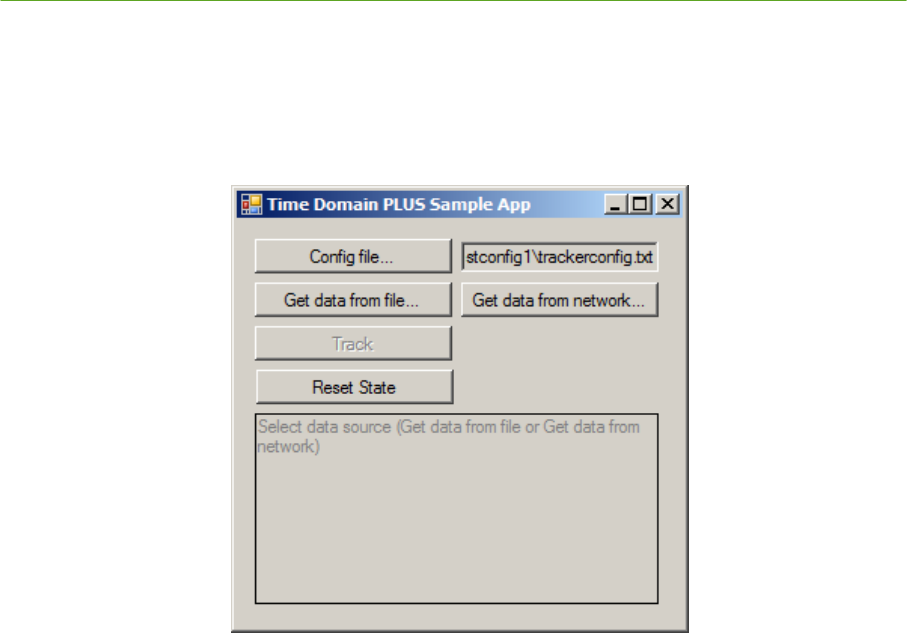
PLUS System Manual Location Software Library 97
Proprietary Information: Do not disclose unless authorized under a Nondisclosure Agreement and the Partner Agreement.
4.7 C# Sample Application Overview
The C# sample application included in the PLUS software install package is intended to demonstrate how
to use the PLUS Location Software Library in a tracking application.
4.7.1 Operating the Sample Application
Figure 4-2: C# Sample Application Screenshot
The buttons on the form are arranged, from top to bottom, in the order they are commonly used.
Although some steps may be skipped depending on the situation, typically the user will select buttons
starting from the top and working down the form.
1. Select a PLUS Location Software Library configuration file using the Config file… button. If
replaying a raw logfile, this step may be skipped since the configuration is saved at the
beginning of raw logfiles.
The last configuration file used is saved in the system registry, so there is no need to repeat this
step until a different configuration file is desired.
2. Select the data source – either Get data from logfile (recorded/simulated data) or Get data
from network (live data). Once a data source has been selected, the Track button is enabled
and the application waits for further instruction before beginning any data processing.
3. Select Track to begin tracking Tags.
Whenever a Tag’s position is updated, a message will display at the bottom of the form with the
coordinates (in meters) of the position.
4. Selecting Reset State brings the software back to its startup state.
4.7.2 Code Walkthrough
The sample application was written in C# using Microsoft Visual Studio 2008. The main source code
file is MainForm.cs.
The sample application’s OCX initialization is performed in the constructor function of MainForm.

98 Location Software Library PLUS System Manual
Proprietary Information: Do not disclose unless authorized under a Nondisclosure Agreement and the Partner Agreement.
This calls the ResetBtn_Click() handler, which sets the application to an initialized, empty state. The
last-used configuration file is loaded, if one is recorded in the system registry.
Once initialization is complete, the code waits for the user to select a data source before continuing.
To enable logging position updates to a .csv file which can be viewed by a typical spreadsheet
application, change the following sections of code:
Uncomment the OutputPositionFile.Visible = true; line at the end of
MainForm.MainForm_Load()
Uncomment the entire body of MainForm.OutputPositionFile_Click().
Change MainForm.tagToSavePositions to the Tag ID for which position updates are to be saved. This
change is in MainForm.OutputPositionFile_Click(), near line 257.
With these changes, the application will have a new button on the form at runtime, which lets the user
select a .csv file to save position updates to from the hardcoded Tag ID.
4.7.2.1 Single-Threaded Apartment Versus Multi-Threaded Apartment
The PLUS Location Software Library is multithreaded and as such most of the events are fired in the
context of its thread, rather than the application’s UI thread.
Threading issues are avoided through the use of single-threaded apartment (STAThread). A more
sophisticated application using multi-threaded apartment (MTAThread) would handle the threading
issues in its event handler(s) by performing a thread-safe transfer of data to the UI thread.
4.7.2.2 MainForm Properties
String configFileName;
Path of the currently loaded configuration file.
StreamWriter positionFile = null;
File for saving Tag position updates.
uint tagToSavePositions = 0;
Tag ID for which positions are saved in the position log file.
4.7.2.3 MainForm Methods and Event Handlers
public MainForm_Load()
Initializes the COM objects and calls ResetBtn_Click(), which sets the application to an intialized, empty state.

PLUS System Manual Location Software Library 99
Proprietary Information: Do not disclose unless authorized under a Nondisclosure Agreement and the Partner Agreement.
public void printMessage(String msg)
Displays the string at the bottom of the main window.
private void ResetBtn_Click(object sender, EventArgs e)
Sets the software to an initialized, empty state and (re)loads the configuration file.
private void ConfigBtn_Click(object sender, EventArgs e)
Displays a File Open dialog for the user to select a PLUS Location Software Library configuration file.
public void LoadConfigFile(String file)
Signals the PLUS Location Software Library to read the configuration stored in the file named by
file
.
private void DataSourceFileBtn_Click(object sender, EventArgs e)
Displays a File Open dialog box where the user can select a raw logfile to provide TOA messages. If the file
contains a configuration header, that will override any standalone configuration previously selected.
private void DataSourceNetworkBtn_Click(object sender, EventArgs e)
Displays a dialog for the user to select a network interface on the local machine for receiving live data.
private void TrackBtn_Click(object sender, EventArgs e)
Starts or stops tracking Tags.
private void trackerEventHandler_NewPosition(int tagId, int tagType, int
positionType, int mapIndex, float X, float Y, float Z, int timestamp, int
batteryState, int buttonState, int motion, int bestReaderIdLow, int
bestReaderIdHigh, int positionFOM, int seqNum)
Event handler for the PLUSTracker.NewTagPosition event; displays the new position.
private void MainForm_FormClosing(object sender, FormClosingEventArgs e)
Cleanup.
private void OutputPositionFile_Click(object sender, EventArgs e)
Selects an output file to which Tag position updates are saved.
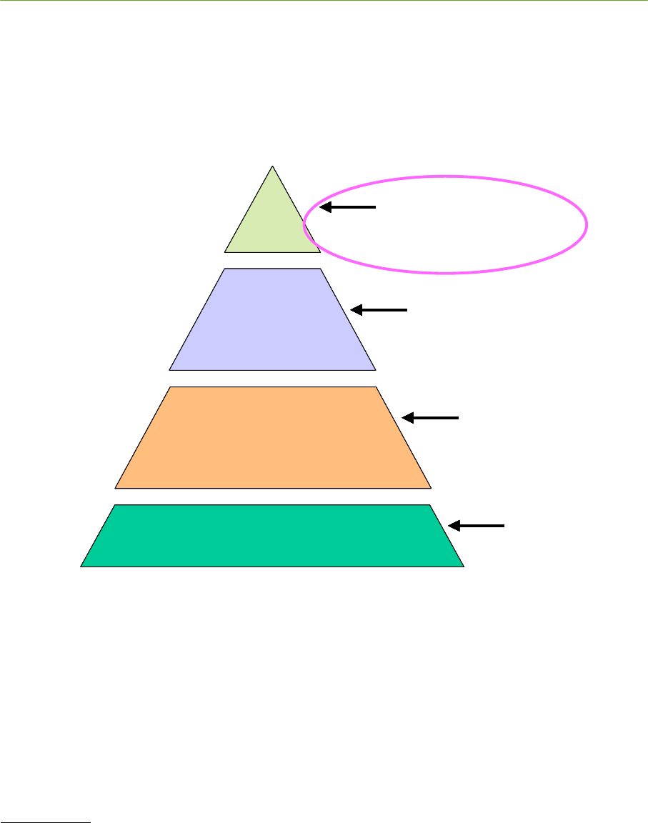
100 Visualizer PLUS System Manual
Proprietary Information: Do not disclose unless authorized under a Nondisclosure Agreement and the Partner Agreement.
5. PLUS Visualizer
5.1 Overview
The PLUS Visualizer application is delivered with the PLUS Location Software Installation. It can be
used to quickly setup and deploy a system, and to determine / diagnose problems.
P L U S L o c a tio n
S o f t w a r e
In s t a lla tio n
S o f t w a r e
P L U S R e a d er
P L U S H a r d w a r e I n fr a st r u c tu r e
S e c t io n 4
P L U S L o c a tio n S o ftw a r e L ib r a r y
H ig h L e ve l S y s te m I n te r f a c e / I n te rfa c e to
L o ca tio n S o ftw a re
S e c t io n 5
P L U S V is u a liz e r
V is u a liz er , I n s ta lla tio n /M a in te n a n ce
S o ftw a re T o o ls
S e c t io n 3
P L U S R e a d er D a ta I n te r f a c e
R e a d e r S o ftw a r e I n te rfa c e -
C o m m a n d s, R e sp o n s e s, R a w T O A P a c k e t
D e f in itio n
S e c t io n 2
P L U S S y ste m I n s ta lla tio n
R e a d e r s , T a g s , S D P , C a b lin g ,
P o w e r , H a r d w a re
C o n fig u r a tio n
P L U S L o c a tio n
S o f t w a r e
In s t a lla tio n
S o f t w a r e
P L U S R e a d er
P L U S H a r d w a r e I n fr a st r u c tu r e
S e c t io n 4
P L U S L o c a tio n S o ftw a r e L ib r a r y
H ig h L e ve l S y s te m I n te r f a c e / I n te rfa c e to
L o ca tio n S o ftw a re
S e c t io n 4
P L U S L o c a tio n S o ftw a r e L ib r a r y
S e c t io n 4
P L U S L o c a tio n S o ftw a r e L ib r a r y
H ig h L e ve l S y s te m I n te r f a c e / I n te rfa c e to
L o ca tio n S o ftw a re
S e c t io n 5
P L U S V is u a liz e r
V is u a liz er , I n s ta lla tio n /M a in te n a n ce
S o ftw a re T o o ls
S e c t io n 5
P L U S V is u a liz e r
S e c t io n 5
P L U S V is u a liz e r
V is u a liz er , I n s ta lla tio n /M a in te n a n ce
S o ftw a re T o o ls
S e c t io n 3
P L U S R e a d er D a ta I n te r f a c e
R e a d e r S o ftw a r e I n te rfa c e -
C o m m a n d s, R e sp o n s e s, R a w T O A P a c k e t
D e f in itio n
S e c t io n 3
P L U S R e a d er D a ta I n te r f a c e
S e c t io n 3
P L U S R e a d er D a ta I n te r f a c e
R e a d e r S o ftw a r e I n te rfa c e -
C o m m a n d s, R e sp o n s e s, R a w T O A P a c k e t
D e f in itio n
S e c t io n 2
P L U S S y ste m I n s ta lla tio n
R e a d e r s , T a g s , S D P , C a b lin g ,
P o w e r , H a r d w a re
C o n fig u r a tio n
S e c t io n 2
P L U S S y ste m I n s ta lla tio n
S e c t io n 2
P L U S S y ste m I n s ta lla tio n
R e a d e r s , T a g s , S D P , C a b lin g ,
P o w e r , H a r d w a re
C o n fig u r a tio n
Figure 5-1: PLUS Interface Layers – Visualizer
In this section, you will become familiar with the Visualizer menus and forms. You will be introduced
to its functional capabilities, and learn what is required to setup and configure the software.
The Control Window
The Visualizer uses a single control window from which you can configure different ―views‖ into the
tracking system. See Figure 5-2: Visualizer Control Window below. In this section, you will learn
about each of these views – what you can gain from each view, and how each view can be customized
to meet your specific needs.
2D Map View
Using the 2D Map View, you can graphically see the location of the PLUS Tags being tracked. You can
customize the view to display / hide system components including Readers, Calibration Tags, and
background image floor plans. You can also customize the ―look‖ of the display including the display
icon and size for the Readers and Tags, and parameters for the grid and floor plan/background image
display.
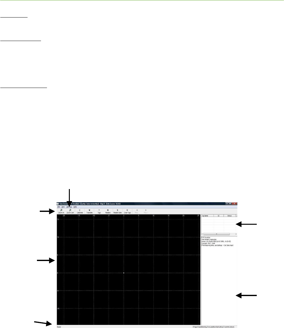
PLUS System Manual Visualizer 101
Proprietary Information: Do not disclose unless authorized under a Nondisclosure Agreement and the Partner Agreement.
List View
Using the List View, you can see the current status of the PLUS Tags and Readers.
Message View
Using the Message View, you can see the message traffic from the PLUS Location Software Library,
including Time Difference of Arrival (TDOA) calculation messages, and Time Of Arrival (TOA)
messages received from the Readers, and the messages output by the location engine as it updates its
internal databases.
Statistical Views
Using forms, you can view the following statistics:
o TDOA for each of the Reader pairs
o Tag statistics by Reader
o Position statistics for the Tags
o Reader statistics.
Figure 5-2: Visualizer Control Window
List View
Frame
Message
Frame
Graphic View
Frame
Status Bar
Toolbar
Menu Bar
Message View
Frame
Menu Bar
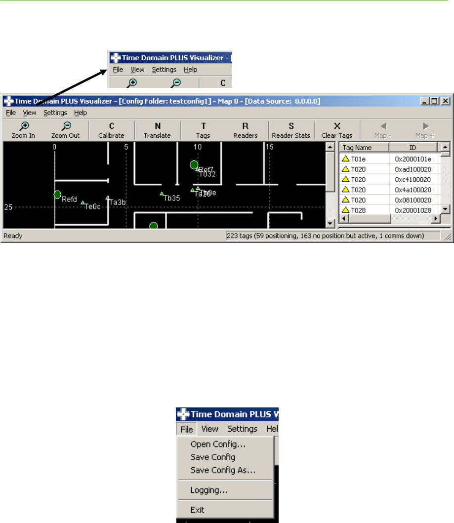
102 Visualizer PLUS System Manual
Proprietary Information: Do not disclose unless authorized under a Nondisclosure Agreement and the Partner Agreement.
5.2 Menu Bar
Figure 5-3: Menu Bar
Use the Menu Bar menu to quickly access:
1) File commands to open and save a configuration folder and control logging of system data.
2) View commands to customize the view in the 2D Map View Frame, and select the message types
output in the Message Frame. The View menu also enables you to open various statistic windows.
3) Setting commands to customize the timeout parameters, 2D view parameters, and the source of the
data input
4) View version information about the Visualizer application
5.2.1 File
Figure 5-4: File Menu
Use the File menu to:
1) Open an existing configuration folder
2) Save the current configuration to the same location as that currently loaded, or to a user specified folder
3) Enable logging of the TOA messages received from the Readers, to a user specified location
4) Enable logging of position data to a user specified file location
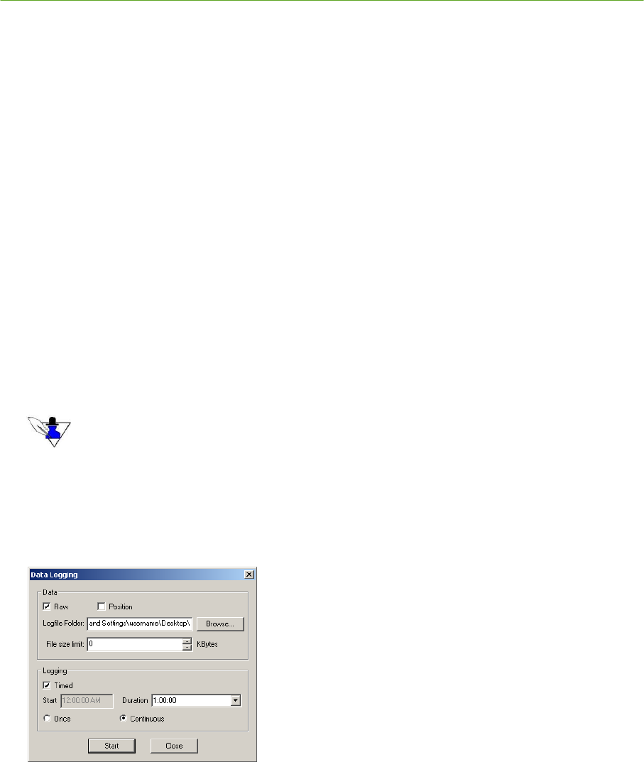
PLUS System Manual Visualizer 103
Proprietary Information: Do not disclose unless authorized under a Nondisclosure Agreement and the Partner Agreement.
File Menu Items:
Open Config… – identify an existing configuration folder. A configuration folder contains two
configuration files, visualizerconfig.txt and trackerconfig.txt, which contain information to:
o Identify the Readers, the MAC address of each, survey data, and calibration data
o Identify the Calibration Tags in the system
o Set the Z value for those Tags with a known height
o Set a default Z for newly detected Tags
o Specify a background image for the floor plan
o Define the zoom and pan settings, as well as the rotation and translation for viewing
Save Config – save the current configuration. If no configuration folder was loaded, e.g. the
configuration was defined interactively, you will be prompted to identify the name of the folder to
which it should be saved.
Save Config As… – save the current configuration to a user specified folder. The user specified folder
then becomes the default configuration folder.
Logging… – log the received TOA messages (raw data) and/or the position data. Refer to
Figure 5-5: Logging Dialog. Use the Browse button to select the directory to which the files will
be saved. Use the File size limit field to limit the size of the logfile (0 = unlimited size).
The filename is defined as the <data type><date><timestamp>.txt. For example, the following files were
generated on 5/18/08 at 4:29:28 PM:
Raw_2008_05_18__16_29_28.txt
Position_2008_05_18__16_29_28.txt
Using the Logging parameters, you can also specify a start time, and/or a time duration to log the
data. For information about the content of the logfiles, see Sections 4.6 Raw Data Log File Formats
and 5.8.1 Position Data.
Start time & duration specified
Figure 5-5: Logging Dialog
Exit – Close the application
If Timed and Continuous, a
new logfile is started after
Duration time. If Timed and
Once, a single logfile is
generated – logging stops after
Duration time.
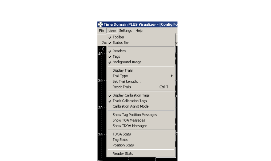
104 Visualizer PLUS System Manual
Proprietary Information: Do not disclose unless authorized under a Nondisclosure Agreement and the Partner Agreement.
5.2.2 View
Figure 5-6: View Menu
Use the View menu to:
1) Turn on/off the display of the Toolbar and/or the Status Bar
2) 2D Map View:
o Turn on/off the graphical display of the Readers
o Turn on/off the graphical display of the Tags
o Turn on/off the graphical display of the background image of the current map.
o Trails:
- Turn on/off the graphical display of trails which show a history of Tag positions;
- Specify parameters for trail display
- Reset the trail display, i.e., erase all trail data currently displayed
o Turn on/off the display of Calibration Tags
o Turn on/off the display of Tags for which a position could not be determined (Presence
Detect)
3) Specify the messages to display in the Message View Frame
4) View Statistics
View Menu Items:
Toolbar – Show/hide the Toolbar in the Control Window
Status Bar – Show/hide the Status Bar in the Control Window
Readers – Show/hide the Readers in the 2D Map View
Tags – Show/hide the Tags in the 2D Map View
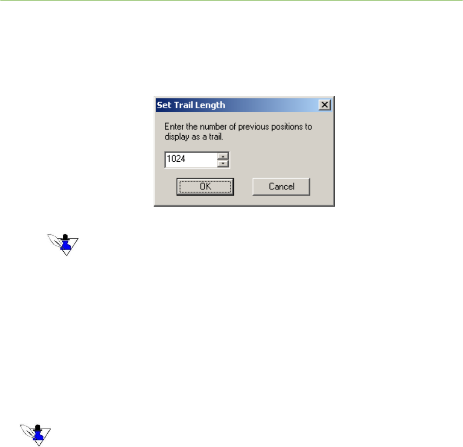
PLUS System Manual Visualizer 105
Proprietary Information: Do not disclose unless authorized under a Nondisclosure Agreement and the Partner Agreement.
Background Image – Show/hide the background image in the 2D Map View.
Display Trails – Display a ―breadcrumb‖ history of Tag locations
Trail Type – Select either nodes or lines as the display type for the Tag trails
Set Trail Length… – Set the desired length for the trail display. Maximum trail length is 1024.
Figure 5-7: Set Trail Length Dialog
Trail history and position statistics are calculated from the same data. If either is reset, the other is reset
as well.
Reset Trails – Restart the trails and reset the Tag position statistics
Display calibration tags – Show/hide the display of the Calibration Tags. See Figure 5-17:
Configure Tags Dialog.
Track calibration tags – Specify, when Calibration Tags are displayed, to show the Calibration
Tags at the positions computed by the system (checked) or at the static positions in the Configure
Tags dialog (unchecked)
Calibration assist mode – Show all Readers with a list of Calibration Tags heard by each Reader.
Also displayed are any configured Reader-Calibration Tag pairs.
Calibration Assist Mode hides the display of all standard (non-calibration) Tags.
Show Solver Messages – Display, in the Message View Frame, the messages output by the PLUS
location engine
Show TOA Messages – Display, in the Message View Frame, the TOA messages output by the
Readers
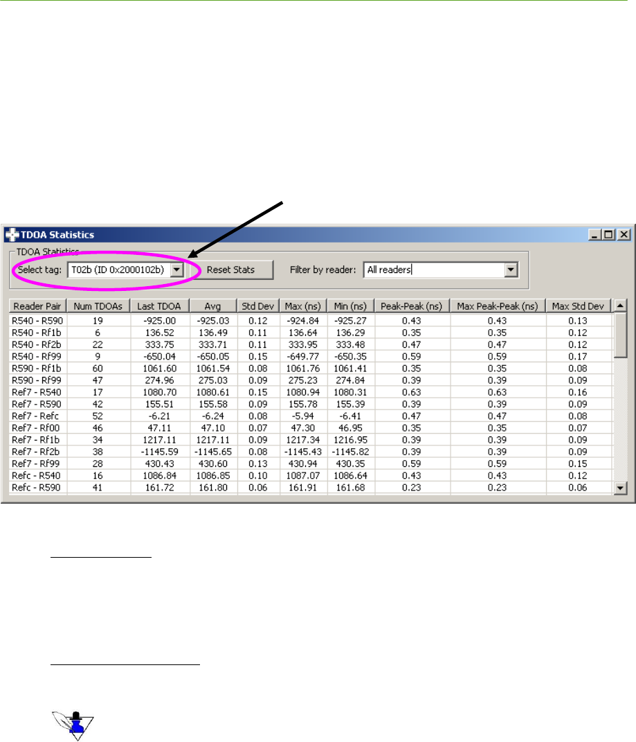
106 Visualizer PLUS System Manual
Proprietary Information: Do not disclose unless authorized under a Nondisclosure Agreement and the Partner Agreement.
Show TDOA Messages – Display, in the Message View Frame, the TDOA messages output by the
PLUS location engine
TDOA Stats – Display the TDOA Statistics dialog. You can use this dialog to view statistical data
about the TDOA messages received for each unique Reader pair, including the number received,
average, standard deviation, maximum and minimum TDOA value, and peak-to-peak values. Note
the statistics can be sorted by clicking the column header on which to sort. The data can be sorted
by Reader Pair, Num TDOAs, Std Dev, Peak-Peak (ns), Max Peak-Peak (ns), or Max Std Dev. The
number of samples for a Reader pair is shown in the Num TDOAs column.
Figure 5-8: TDOA Statistics Dialog
TDOA Statistics
o Select tag – Select the Tag for the TDOA statistics to view
o Reset Stats – Select this button to reset the TDOA statistics for the selected Tag
o Filter by Reader – Reduce the amount of data presented by selecting a Reader to filter by.
Statistics by Reader Pair
The following is a list of the statistical fields and their meaning.
These statistics are computed using the last number of TDOA messages (Num TDOAs) received for a
given Reader pair, up to 1024 samples. Num TDOAs is shown in the second column of the form.
o Reader Pair – The Reader pair for which the statistics apply
o Num TDOAs – Number of TDOA messages used in computing the statistics for that
Reader pair
o Last TDOA – Last TDOA value, in nanoseconds (ns), received in a TDOA message for the
given Reader pair
o Avg – Average of the TDOA values received for the given Reader pair
o Std Dev – Standard deviation of the TDOA values received for the given Reader pair
ID of Tag for which the TDOA statistics apply
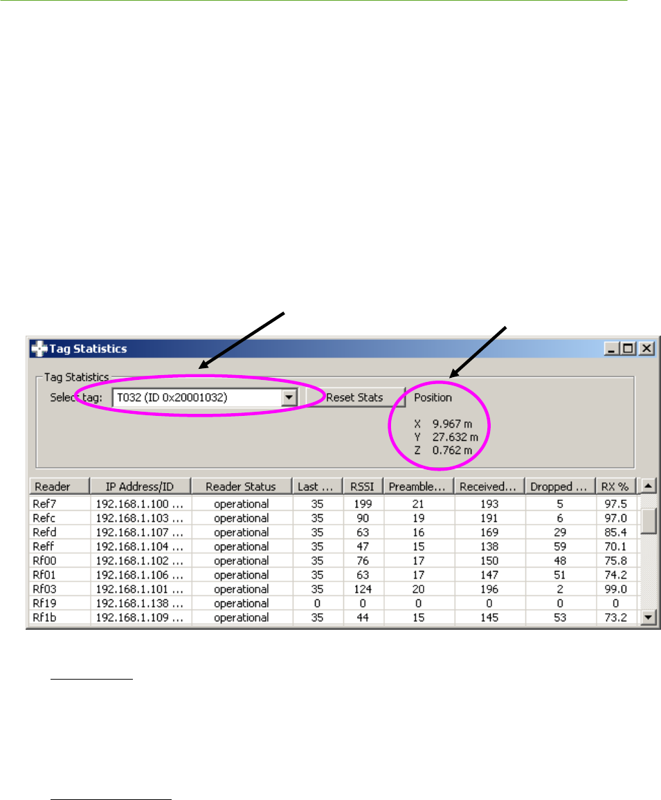
PLUS System Manual Visualizer 107
Proprietary Information: Do not disclose unless authorized under a Nondisclosure Agreement and the Partner Agreement.
o Max (ns) – Maximum TDOA value received for the given Reader pair
o Min (ns) – Minimum TDOA value received for the given Reader pair
o Peak-Peak (ns) –Value of the maximum peak value minus the minimum peak value for the
last TDOA message received for the given Reader pair
o Max Peak-Peak (ns) –Value of the maximum peak-to-peak value received in the last TDOA
message received for the given Reader pair
o Max Std Dev – Maximum standard deviation of the TDOA values received for the given
Reader pair
Tag Stats – display the Tag Statistics dialog. You can use this dialog to view historical data, for
each Tag, including current status, last packet sequence number heard, signal strength, preamble
count, number of received packets, number of dropped packets, RX%, and current position. Note
the statistics can be sorted by clicking the column header on which to sort. The data can be sorted
by Reader, IP Address/ID, RSSI, Received Packets, Dropped Packets, or RX %.
Figure 5-9: Tag Statistics Dialog
Tag Statistics
o Select tag – Select the Tag for the statistics to view
o Reset Stats – Select this button to reset the Tag statistics for the selected Tag
o Position – Read-only field which shows the Tag’s current position calculated by the PLUS
location engine
Statistics by Reader
The following is a list of the statistical fields and their meaning:
ID of Tag for which the
Tag Statistics apply
Tag current position
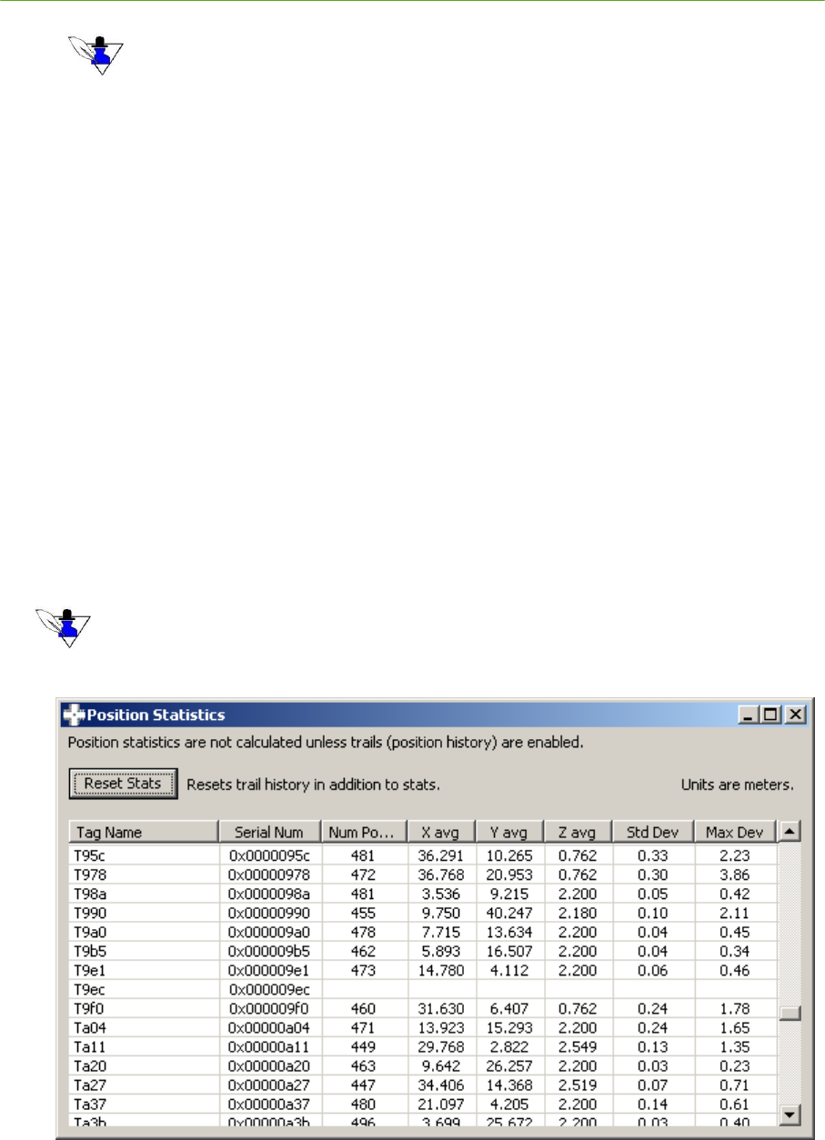
108 Visualizer PLUS System Manual
Proprietary Information: Do not disclose unless authorized under a Nondisclosure Agreement and the Partner Agreement.
These statistics are computed using the last number of Tag packets (Received Packets) received from
the selected Tag.
o Reader – Name of Reader for which the statistics apply
o IP Address/ID – MAC address of the Reader
o Status – Operational status of the Reader—COMMS DOWN or operational. A Reader is
marked as COMMS DOWN if a packet has not been received within a given timeout. The
timeout is set using the Menu Bar / Settings / Timeouts… submenu item. Figure 5-13:
Timeouts Dialog
o Last Seq # – Sequence number of the last packet received from the specified Tag
o RSSI – Received Signal Strength Indicator (RSSI) for the last packet received from the
specified Tag
o Preamble Cnt – Status indicator for the last received packet is for diagnostics use only
o Received Packets – Number of packets received from the specified Tag
o Dropped Packets – Number of packets that were not received, or received with errors by
the Reader. The value is determined using the sequence number of the packet.
o RX % – Percentage of packets received by the Reader calculated as
Received Packets / Total Packets Transmitted
Position Stats – display the Position Statistics dialog. You can use this dialog to view statistical
data about the Tag position, including the average x, y, z location, standard deviation, and
maximum deviation. Note the statistics can be sorted by clicking the column header on which to
sort. The data can be sorted by Tag Name, Serial Num, or Num Positions.
Position statistics are only valid for a stationary Tag in a non-changing environment. Position statistics are
evaluated from a buffer of the most recent 1024 position results, or the value in the Num Positions column,
whichever is less.
Figure 5-10: Position Statistics Dialog
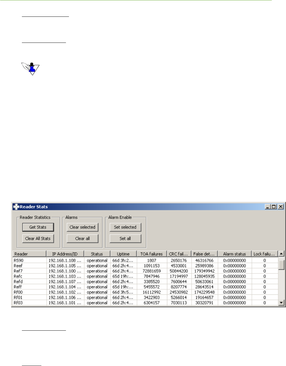
PLUS System Manual Visualizer 109
Proprietary Information: Do not disclose unless authorized under a Nondisclosure Agreement and the Partner Agreement.
Position Statistics
o Reset Stats – Select this button to reset the position statistics for the selected Tag
Statistics by Tag
The following is a list of the statistical fields and their meaning:
The “Num Positions” column indicates the number of data points used for the display statistics.
o Tag Name – Name of the Tag for which the position stats apply
o Serial Num – Serial number of the Tag for which the position statistics apply
o Num Positions – Number of positions actually used in computing the statistics for the
specified Tag
o X avg – Average X position computed for the specified Tag
o Y avg – Average Y position computed for the specified Tag
o Z avg – Average Z position computed for the specified Tag
o Std Dev – Standard deviation of the current position from the last Num Positions for the Tag
o Max Dev – Maximum standard deviation for the last Num Positions for the specified Tag
Reader Stats – display the Reader Stats dialog. You can use this dialog to review the current and
historical data about each Reader, including the IP address, operational status, TOA failures, CRC
failures, false detections, alarm status, and lock failures. If you are getting lock failures for a given
Reader, you should also be receiving alarms for that Reader.
Figure 5-11: Reader Stats Dialog
Reader Statistics
o Get Stats – Select this button to retrieve the latest statistics for all Readers
o Clear All Stats – Select this button to reset the statistics on all Readers
Alarms
o Clear selected – Select this button to clear the alarm condition for the selected Reader
o Clear All – Select this button to clear the alarm condition for all Readers
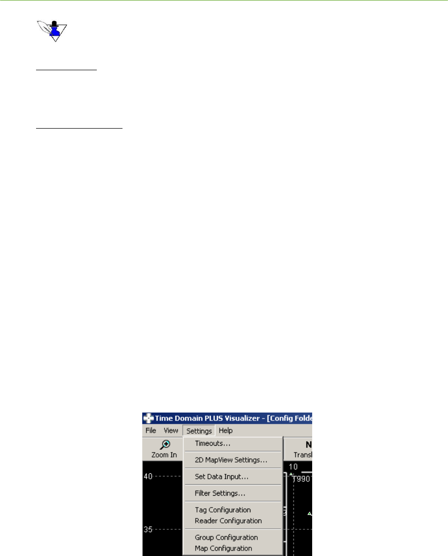
110 Visualizer PLUS System Manual
Proprietary Information: Do not disclose unless authorized under a Nondisclosure Agreement and the Partner Agreement.
When an alarm condition arises, you MUST investigate and resolve the problem. Once resolved,
manually clear the alarm using the “Clear selected” or “Clear all” buttons. See Sections 2.7
Troubleshooting Reader Communications and 5.9 Troubleshooting the Visualizer for more information.
Alarm Enable
o Set selected – Select this button to enable alarms for the selected Reader
o Set All – Select this button to enable alarms for all Readers
Statistics by Reader
The following is a list of the statistical fields and their meaning:
o Reader – Name of the Reader for which the position statistics apply
o IP Address/ID – MAC address of the Reader
o Status – Operational status of the Reader—COMMS DOWN, operational, or not used. A
Reader is marked as COMMS DOWN if a packet has not be received within a given
timeout. The timeout is set using the Menu Bar / Settings / Timeouts… submenu item.
See Figure 5-13: Timeouts Dialog
o Uptime – Time lapsed since power-up or the last reboot of the Reader
o TOA failures – Number of computed TOA values that did not meet reliability criteria
o CRC failures – Number of Tag packets received that failed the CRC check
o False detects – Number times a signal was detected but was not a received Tag packet
o Alarm status – Current alarm status bitmask for the given Reader.
- Bit 0 indicates that the Reader’s phase-locked loop oscillator has lost
synchronization with the SDP.
- Bit 1 indicates that a reboot has occurred.
- Bit 2 indicates a Sync Marker failure.
o Lock failures – Number of times the Reader lost lock (was out of phase lock) with the SDP
5.2.3 Settings
Figure 5-12 : Settings Menu
Use the Settings menu to:
1) Specify timeout parameters for both Readers and Tags
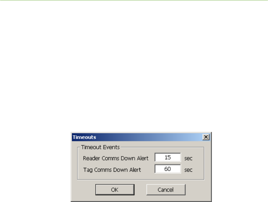
PLUS System Manual Visualizer 111
Proprietary Information: Do not disclose unless authorized under a Nondisclosure Agreement and the Partner Agreement.
2) Specify 2D view parameters, including the units for display (meters or feet) and parameters for the
display of Tag and Readers.
3) Specify the data source as either a NIC card on which to receive data from the Readers, or a logfile
4) Specify the settings for the speed limit and moving average filters used by the PLUS location
engine algorithms
5) Configure the PLUS system Tags
6) Configure the PLUS system Readers
7) Configure the PLUS system groups
8) Configure the PLUS system maps
Settings Menu Items:
Timeouts… – set the times for the system timeout events.
Figure 5-13: Timeouts Dialog
o Reader Comms Down Alert – Specify the time (in seconds) that a Reader is to be marked
―down‖ (Tag icon turns red) if messages are not received within the specified timeframe. If
a Reader does not receive any Tag messages for 10 seconds, it will send a ―keepalive‖ Tag
message with a Tag ID of 0, to indicate to the application that the Reader is still functional.
The Reader color is red when communication is down, and green when the communication
is up.
o Tag Comms Down Alert – Specify the time (in seconds) that a Tag is to be marked ―down‖
(Tag icon turns yellow) if messages are not received from that Tag by any Readers within
the specified timeout. The Tag color is red when communication is down, and green when
the Tag is operational.
2D MapView Settings… – specify the display parameters for the 2D Map View.
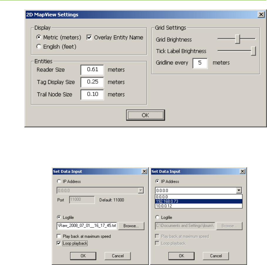
112 Visualizer PLUS System Manual
Proprietary Information: Do not disclose unless authorized under a Nondisclosure Agreement and the Partner Agreement.
Figure 5-14: 2D MapView Settings
Set Data Input… – specify the source of the Reader data.
Figure 5-15: Set Data Input Dialog
o IP Address – Select the IP Address radio button to specify that TOA messages will be
received via the network and, using the dropdown list of available IP addresses, select the
connection on which to receive the data. Selecting the 0.0.0.0 IP address causes the
application to listen on all available network interfaces.
o Logfile – Select the Logfile radio button to specify that the TOA messages will be read
from a logfile. Use the Browse button to identify the name of this input logfile.
Select Play back at maximum speed to replay the logfile at maximum speed rather than
the rate it was recorded.
Select Loop playback to repeat the logfile when it is finished.
Filter Settings… – specify the parameters for the Speed Limit and Averaging filters used by the PLUS
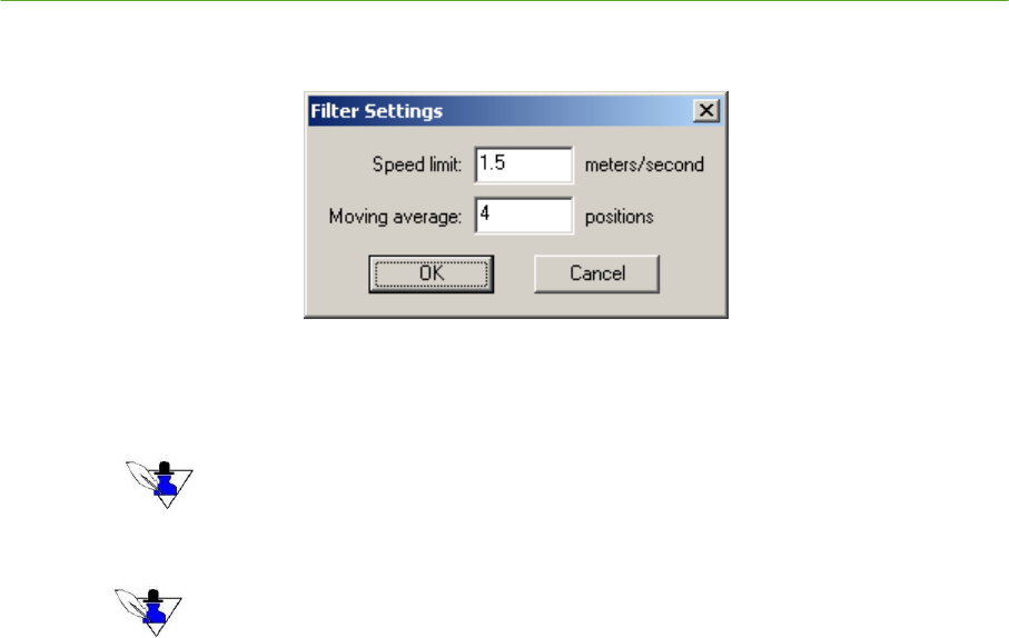
PLUS System Manual Visualizer 113
Proprietary Information: Do not disclose unless authorized under a Nondisclosure Agreement and the Partner Agreement.
location engine algorithm.
Figure 5-16: PLUS Location Software Library Algorithm Filter Settings
o Speed limit – Enter the speed limit of the Tags for use in the Speed Limit filter. The
default value is 1.5 meters/second which is normal walking speed.
Enter 0 to disable the Speed Limit filter.
o Moving average – Enter the depth for use in the Averaging filter
Enter 0 to disable the Averaging filter. Enter a depth between 2 and 32 for the number of positions
to average (a depth of 1 has the same effect as turning the filter off).
Tag Configuration – display the Tag Configuration dialog from which you can interactively
configure single or multiple Tags. The Tags listed are those that have been heard by a PLUS
Reader. Using this form, you can:
o Designate which Tags are Calibration Tags (―Cal Tags‖)
o For Calibration Tags only, enter the Tag X, Y and Z coordinates in the units specified in the
Settings / 2D MapView Settings… (see 5.2.3 Settings)
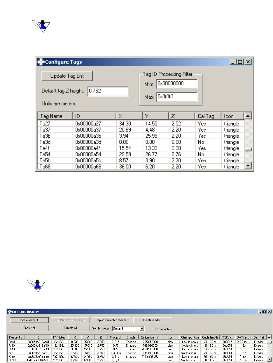
114 Visualizer PLUS System Manual
Proprietary Information: Do not disclose unless authorized under a Nondisclosure Agreement and the Partner Agreement.
o Rename a Tag
You can use this functionality to customize a naming convention. For example, you can name all Tags
tracking infusion pumps with the same prefix to enable easy recognition of what resource a Tag
represents.
o Change the display symbol associated with a given Tag
Figure 5-17: Configure Tags Dialog
Reader Configuration – display the Configure Readers dialog from which you can interactively
configure single or multiple Readers. Using this form, you can:
o Rename a Reader
o Enter the Reader X, Y, and Z coordinates in the units specified in the Settings / 2D MapView
Settings… (see 5.2.3 Settings)
o Set a Reader’s group membership(s)
o Change the display icon
o Enter the Reader hardware parameters of chain position and cable length. The chain position
defines where the selected Reader is in the chain – not last or last, and the cable length
designates the cable length from the SDP to the selected Reader – 0-30, 30-60, or 60-90 meters.
Chain position and cable length are automatically determined by Reader 2.0 hardware, so these fields are
only configurable for earlier Reader versions.
Figure 5-18: Configure Readers Dialog
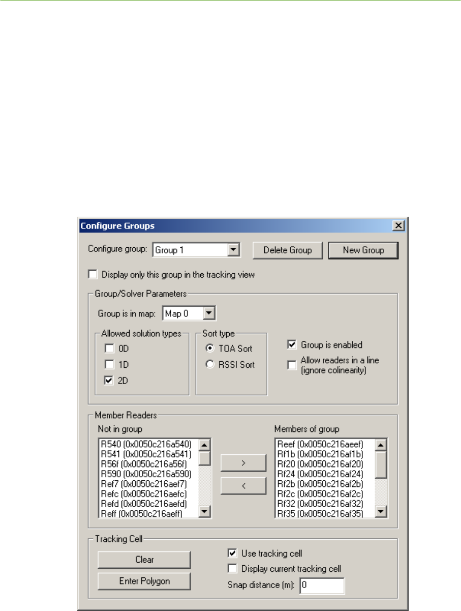
PLUS System Manual Visualizer 115
Proprietary Information: Do not disclose unless authorized under a Nondisclosure Agreement and the Partner Agreement.
Group Configuration – display the Configure Groups dialog from which you can interactively
configure groups. Using this form, you can:
o Select a group to configure
o Create a new group
o Delete a group. Group 0 cannot be deleted. Readers in the group will be moved to group 0 if
they are not members of any other groups.
o Select the map of which the current group is a member.
o Enable/disable the group, enable/disable solver types (0D, 1D, 2D), and set solver parameters.
o Delete the group’s tracking cell
o Graphically enter (in the 2D Map View) a new tracking cell.
o Add and remove Readers to and from the group.
Figure 5-19: Configure Groups Dialog

116 Visualizer PLUS System Manual
Proprietary Information: Do not disclose unless authorized under a Nondisclosure Agreement and the Partner Agreement.
Group/Solver Parameters
o Group is in map – Select the map in which this group is located.
o Allowed solution types – Enable/disable 0D (presence detect), 1D (linear), and 2D solutions for
this group.
Enabling 0D enables Presence Detect mode, in which a Tag whose position cannot be
determined is assigned to the location of the Reader with the strongest received signal
from that Tag. The Tag’s name is listed under the Reader’s name.
o Sort type – Select TOA Sort for most instances.
o Use tracking cell – Enable/disable the tracking cell boundary.
o Allow readers in a line (ignore colinearity) – Allow solutions from colinear readers.
Member Readers
o Move readers in and out of the group.
Tracking Cell
o Clear – Resets the tracking cell to an empty state.
o Enter Polygon – Starts a new tracking cell which is entered graphically by clicking on the
tracking cell vertices in the Tracking View. To remove the last-entered vertex, press
Backspace. To cancel entry, press Escape.
o Display current tracking cell – Toggles display of the currently configured tracking cell in the
Tracking View.
o Snap distance – You may enter a snap distance for the tracking cell. If a snap distance is
defined, Tags that are located outside the tracking cell but less than the snap distance from the
tracking cell will be shown on the boundary of the tracking cell. If tag solutions are outside of
the snap distance, they will be discarded.
Map Configuration – display the Configure Maps dialog from which you can interactively configure
maps. Using this form, you can:
o Select a map to configure
o Create a new map
o Delete a map. Map 0 cannot be deleted. Groups in the map will be moved to Map 0.
o Select and calibrate a background image for the map.
o Delete the map’s tracking cell
o Graphically enter (in the 2D Map View) a new tracking cell
o Add and remove groups to and from the map
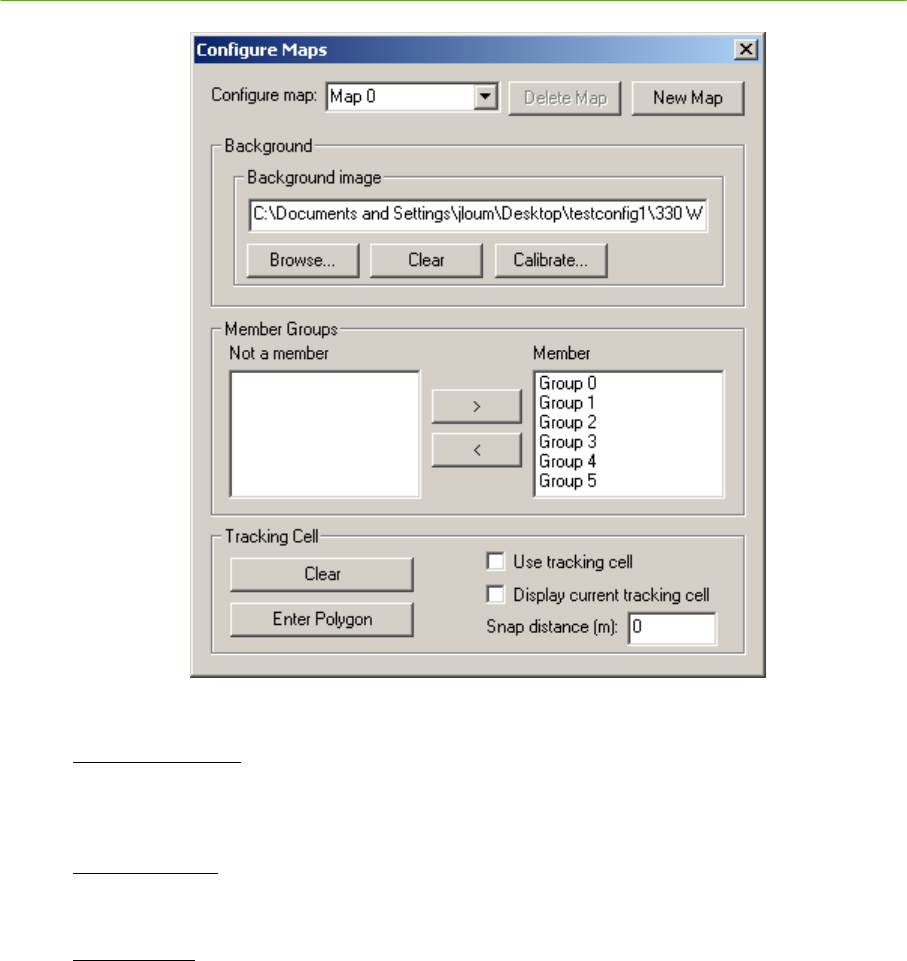
PLUS System Manual Visualizer 117
Proprietary Information: Do not disclose unless authorized under a Nondisclosure Agreement and the Partner Agreement.
Figure 5-20: Configure Maps Dialog
Background Image
o Select and scale an image file (bitmap, JPEG, PNG, GIF, TIF) for use as a background image
for this map.
Member Groups
o Move groups in and out of the map. Groups may be members of only one map at a time.
Tracking Cell
o Clear – Resets the tracking cell to an empty state.
o Enter Polygon – Starts a new tracking cell which is entered graphically by clicking on the
tracking cell vertices in the Tracking View. To remove the last-entered vertex, press
Backspace. To cancel entry, press Escape.
o Display current tracking cell – Toggles display of the currently configured tracking cell in the
Tracking View.
o Snap distance – You may enter a snap distance for the tracking cell. If a snap distance is
defined, Tags that are located outside the tracking cell but less than the snap distance from the
tracking cell will be shown on the boundary of the tracking cell. If tag solutions are outside of
the snap distance, they will be discarded.
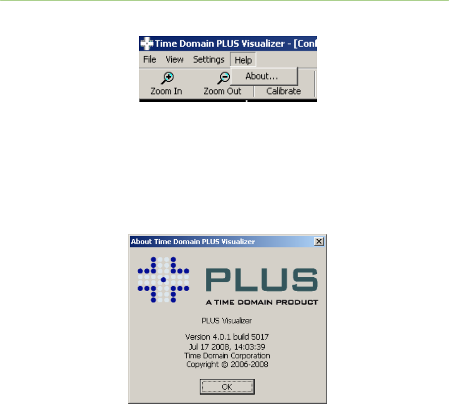
118 Visualizer PLUS System Manual
Proprietary Information: Do not disclose unless authorized under a Nondisclosure Agreement and the Partner Agreement.
5.2.4 Help
Figure 5-21: Help Menu
Use the Help menu to:
1) View the About Box showing the version information of the PLUS Visualizer software
Help Form Fields:
About… – display version information about the PLUS Visualizer executable
OK – Select the OK button to close the About form
Figure 5-22: About Box Dialog
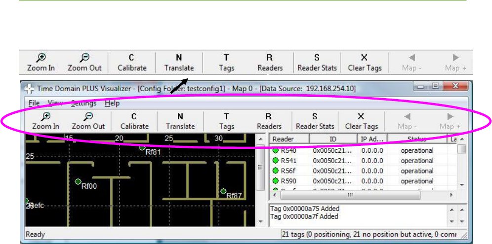
PLUS System Manual Visualizer 119
Proprietary Information: Do not disclose unless authorized under a Nondisclosure Agreement and the Partner Agreement.
5.3 Toolbar
Figure 5-23: Toolbar Menu
Use the Toolbar menu to:
1) Quickly access buttons to:
o Zoom in / out the graphical display
o Calibrate the Readers using the Calibration Tags
o Translate and/or rotate the Reader coordinate system for proper alignment with the
background image
o Change the mode of the List View to Tags or Readers
o Display Reader statistics
o Purge Tags that are no longer heard within the system
2) Receive notification of Reader alarms
Toolbar Buttons:
Zoom In (+) – Select this button to magnify the view displayed in the 2D Map View frame
Zoom Out (-) – Select this button to decrease the view displayed in the 2D Map View frame
Calibrate – Select this button to bring up the Calibration dialog. Use this dialog to:
o Select single or multiple groups for calibration. For each group, the calibration algorithm
selects a reference Reader and, using that Reader’s and the Calibration Tags’ known
positions, calculates the calibration offset for each Reader for the group. A Reader will
have one calibration offset for each group of which the Reader is a member.
o Include or exclude pairings of Readers and Calibration Tags (Reader-Tag Associations)
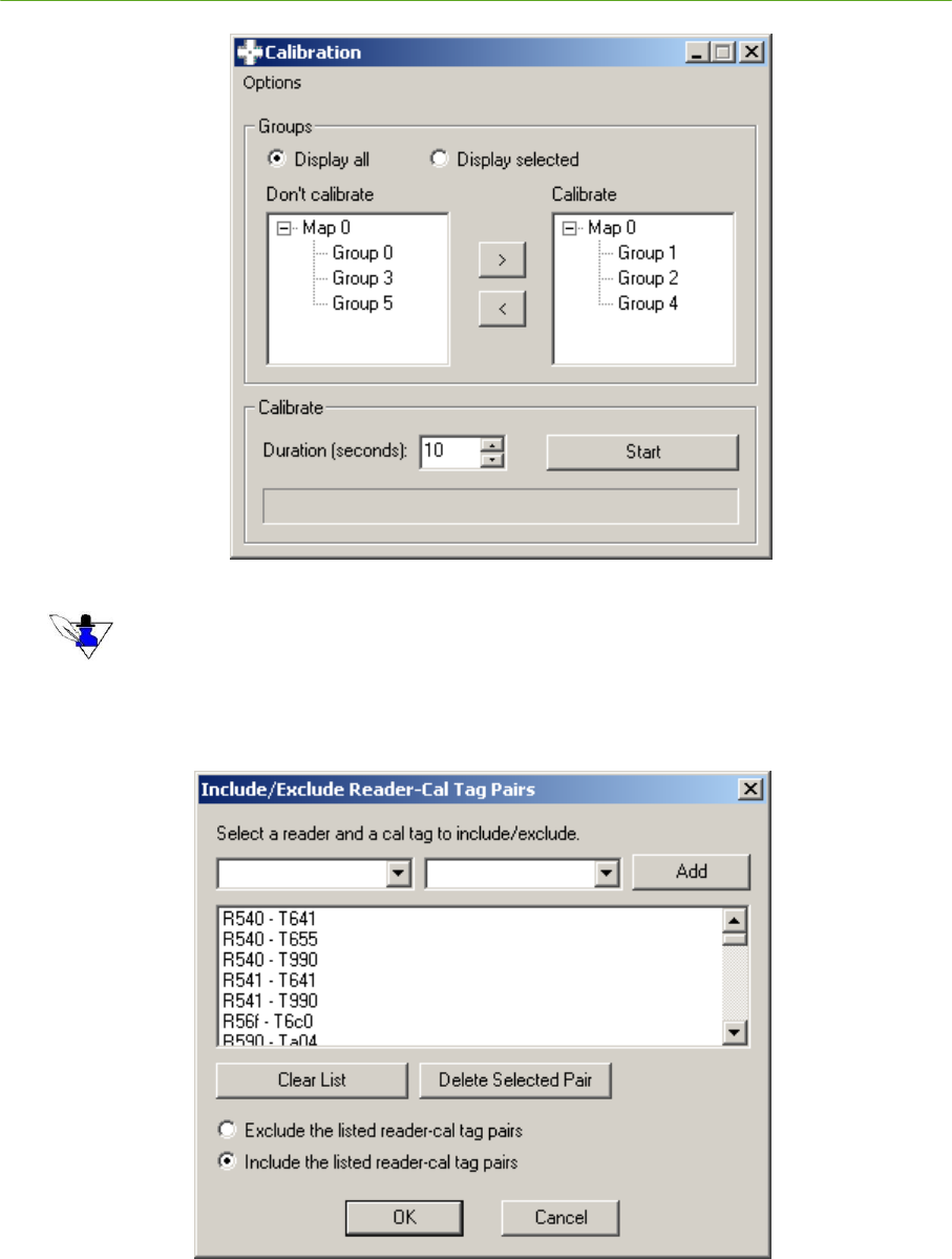
120 Visualizer PLUS System Manual
Proprietary Information: Do not disclose unless authorized under a Nondisclosure Agreement and the Partner Agreement.
1) Specify the number of seconds to collect data to use in determining the calibration value
Enter a minimum of 10 seconds – 30 to 50 seconds is recommended. Maximum is 60 seconds.
2) If desired, specify Reader-Cal Tag Associations with the Include/Exclude Reader-Cal Tag Pairs
dialog. Select the Set tag-reader associations… menu item in the Calibration window to display
it.
3) Use the pull-down lists for Readers and Tags to add combinations to the list. Make sure the
Include the listed reader-cal tag pairs radio button is checked so that only the specified
combinations will be used for calibration.
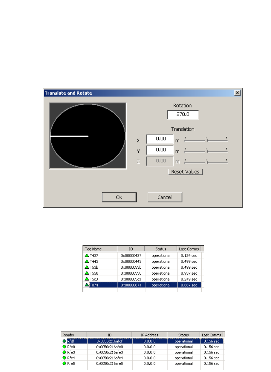
PLUS System Manual Visualizer 121
Proprietary Information: Do not disclose unless authorized under a Nondisclosure Agreement and the Partner Agreement.
4) Select the Start button in the Calibration dialog. A progress bar will denote the status of the
calibration process. If you wish to stop calibration before it is complete, select the Stop button.
5) Review the results of the calibration. Select OK to apply the new results if they are satisfactory.
Translate – Select this button to dynamically rotate and/or translate the Reader coordinate system
into the coordinate system of the graphical display. NOTE that the Z value is not currently
selectable.
o Use the dial to define the rotation
o Use either the slider or key-in field to set the X and Y values for translation.
Figure 5-24: Translate Dialog
Tags – Select this button to change the List View to ―tag view‖ mode. In this mode, the List View
shows status of the Tags.
Figure 5-25: Tag List View
Readers – Select this button to change the List View to ―Reader view‖ mode. In this mode, the
List View shows status of the Readers.
Figure 5-26: Reader List View
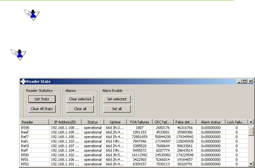
122 Visualizer PLUS System Manual
Proprietary Information: Do not disclose unless authorized under a Nondisclosure Agreement and the Partner Agreement.
The IP Address column will be 0.0.0.0 for Readers whose IP addresses are not known, or when a logfile
is being played back.
Reader Stats – Select this button to display the Reader Stats dialog.
See Figure 5-11: Reader Stats Dialog for more information about this dialog.
If a Reader alarm condition occurs such as it has lost synchronization with the SDP, the Reader Stats
button flashes, alerting you to display the Reader Stats and resolve the problem. See Section 5.9
Troubleshooting the Visualizer for more information.
Figure 5-27: Reader Stats
Clear Tags – Select this button to clear Tags with a status of COMMS DOWN from the Tag list
Map – and Map + - Select these buttons to cycle through the available maps. If only one map is
configured these buttons are disabled.
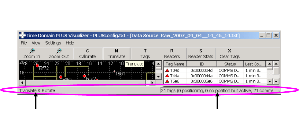
PLUS System Manual Visualizer 123
Proprietary Information: Do not disclose unless authorized under a Nondisclosure Agreement and the Partner Agreement.
5.4 Status Bar
Figure 5-28: Status Bar
Use the Status menu to:
1) View command descriptions
2) View Tag summary statistics, including a total Tag count, and the number of Tags positioning,
active, and with a comms down status.
Tag summary statistics
Command description

124 Visualizer PLUS System Manual
Proprietary Information: Do not disclose unless authorized under a Nondisclosure Agreement and the Partner Agreement.
5.5 2D Map View Frame
Figure 5-29: 2D Map View Frame
Use the 2D Map View Frame to:
1) Track Tags
2) View the relative location of the Readers
3) View the location of the both the Tags and the Readers within a room, building, or other physical
reference
4) View the status of the Tags and Readers
5) View a history of Tag locations
6) Zoom-in and zoom-out the display (drag with right mouse button, scroll with mouse wheel, or use
+, -, or = keys)
7) Pan the display (left mouse button or arrow keys)
8) View a list of Tags for which a position could not be determined
9) View Calibration Tag and Reader pairing in Cal Assist Mode.
10) View and enter tracking cells for groups and maps from the Configure Groups and Configure Maps
dialogs.

PLUS System Manual Visualizer 125
Proprietary Information: Do not disclose unless authorized under a Nondisclosure Agreement and the Partner Agreement.
You can customize the 2D Map View Frame display by selecting what you want to display from the Menu Bar /
View submenu. See Section 5.2.2 View above.
2D Map View Fields:
Double click a Reader icon to display the Configure Readers dialog, with the selected Reader
highlighted. See Section 5.2.3 Settings for more information about this dialog.
Double click a Tag icon to display the Configure Tags dialog, with the selected Tag highlighted.
See Section 5.2.3 Settings for more information about this dialog.
Right click either Reader or Tag icons to display a context menu with shortcuts to views such as
Tag Stats, Position Stats, or Reader Stats.
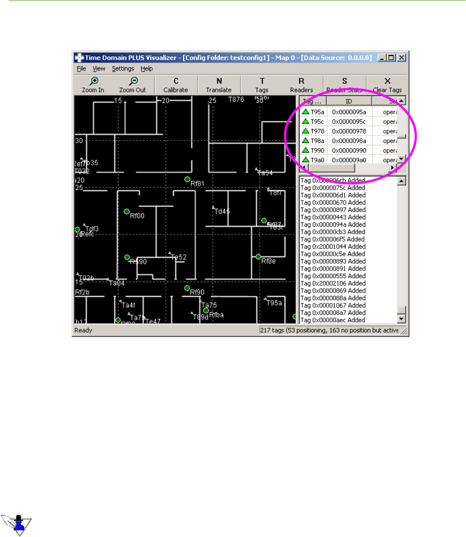
126 Visualizer PLUS System Manual
Proprietary Information: Do not disclose unless authorized under a Nondisclosure Agreement and the Partner Agreement.
5.6 List View Frame
Figure 5-30: List View Frame
Use the List View Frame to:
1) View a tabular list of Tags and the their status
2) View a tabular list of Readers and their status
3) Change the name and icon properties of a selected Tag
4) Change the name and icon properties of a selected Reader
5) Configure the Readers
6) Configure the Tags
You can customize the List View display by selecting what you want to display using the Toolbar buttons “Tags”
and “Readers”. See Section 5.3 Toolbar.
List View Fields:
If the list contains Reader data:
a) Double click the line with the desired Reader, or right mouse click the line with the desired
Reader and select Configure Reader…, to invoke the Configure Readers dialog discussed in
Section 5.2.3 Settings.
b) Right mouse click the line with the desired Reader and select:
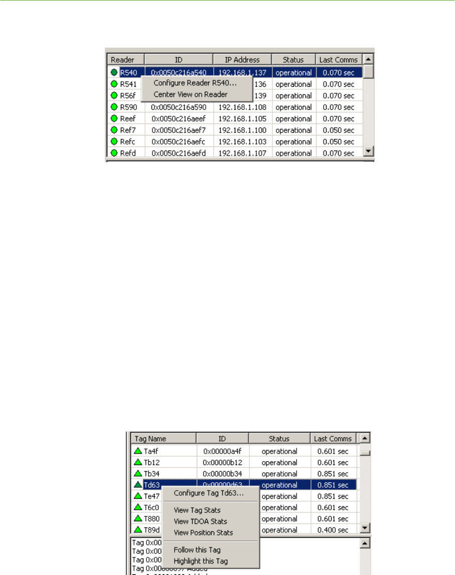
PLUS System Manual Visualizer 127
Proprietary Information: Do not disclose unless authorized under a Nondisclosure Agreement and the Partner Agreement.
o Center View on Reader – Centers the 2D Map View on the Reader to assist in visually
finding the Reader on the display.
Figure 5-31: Reader List View Menu
If the list contains Tag data:
a) Double click the line with the desired Tag, or right mouse click the line with the desired Tag
and select Configure Tag…, to invoke the Configure Tags dialog discussed in Section 5.2.3
Settings.
b) Right mouse click the line with the desired Tag and select:
o View Tag Stats – Select View Tag Stats to invoke the Tag Statistics form discussed in
Section 5.2.2 View
o View TDOA Stats – Select View TDOA Stats to invoke the TDOA Statistics form
discussed in Section 5.2.2 View
o View Position Stats – Select View Position Stats to invoke the Position Statistics form
discussed in Section 5.2.2 View
o Follow this Tag – Continually centers the 2D Map View on the Tag
o Highlight this Tag – Enlarges the Tag in the 2D Map View for better visibility. Only
one Tag can be highlighted at a time.
Figure 5-32: Tag List View Menu
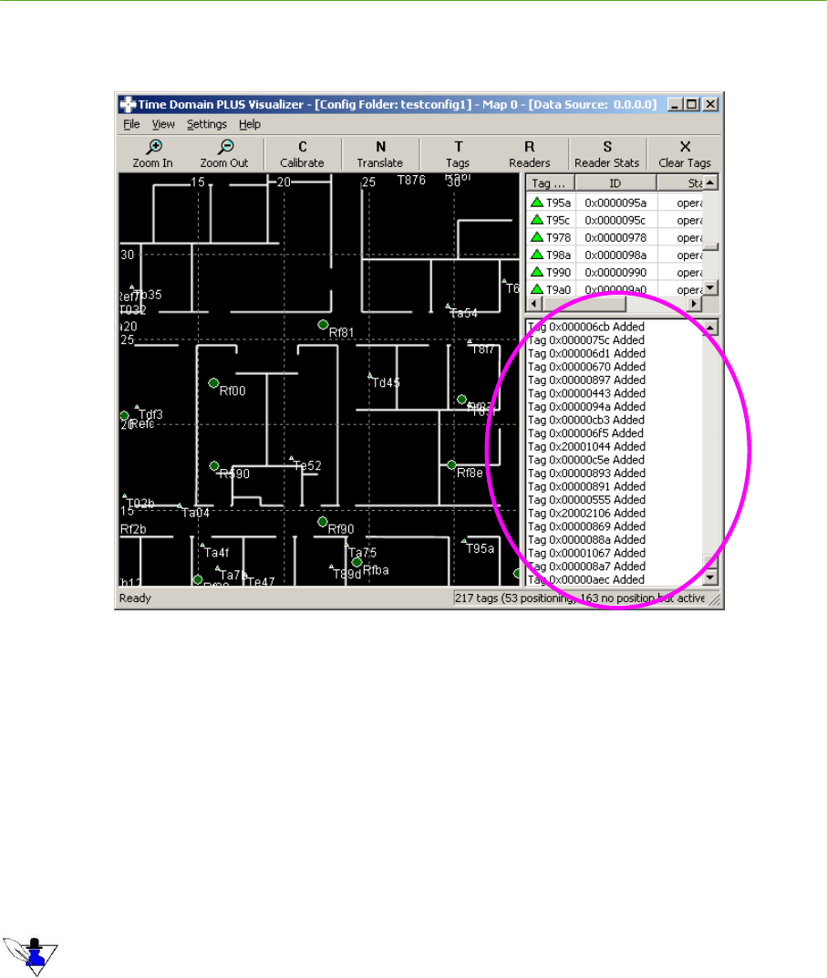
128 Visualizer PLUS System Manual
Proprietary Information: Do not disclose unless authorized under a Nondisclosure Agreement and the Partner Agreement.
5.7 Message View Frame
Figure 5-33: Message View Frame
Use the Message View Frame to display the following messages:
1) TOA messages from the Readers
2) TDOA messages from the PLUS location engine
3) ―Solved‖ status messages from the PLUS location engine
4) ―Communications down‖ messages for both the Tags and the Readers
5) Messages indicating that a Reader has been added to the system
6) Messages indicating that a new Tag has been added to the system
You can customize the List View Frame display by selecting what messages you want to display from the Menu
Bar / View submenu -- see Section 5.2.2 View. The “Communications down”, Reader added, and Tag added
messages are always displayed.

PLUS System Manual Visualizer 129
Proprietary Information: Do not disclose unless authorized under a Nondisclosure Agreement and the Partner Agreement.
5.8 Logfile Formats
5.8.1 Position Data
The Position Data is logged to the file specified via the Menu Bar / File / Logging… submenu item.
See Section 5.2 Menu Bar.
5.8.1.1 Position Data Record
Position data records are the timestamped Tag positions as computed by the PLUS location engine.
Timestamp Time the position data was recorded, represented as the number of 100-
nanosecond intervals since January 1, 1601 (64 bits)
TAGPOS Record type TAGPOS
tagID ID of the Tag whose position is being reported
X X coordinate of the solution
Y Y coordinate of the solution
Z Z coordinate of the solution
NumReceivers Number of receivers which participated in the solution, i.e. heard the Tag
Confidence Percent confidence factor for the solution – the higher the factor the greater the
confidence of the solution
SeqNum Sequence number from the Tag payload that cycles from 0 to 63
Best Receiver ID of the Reader with the best TOA solution – statistical weight based on
Reader RSSI and proximity to the Tag.
5.9 Troubleshooting the Visualizer
Lost contact with a Reader
Lost Reader contact usually occurs due to network based problems. Check all cables and
connections between:
1) The PC and the SDP
2) The SDP and its connected Readers
3) Any daisy chained Readers
If all connections are good, reboot the Reader, or reset the power to the PLUS Reader itself. See
# Timestamp, TAGPOS, tagID, X, Y, Z, NumReceivers, Confidence, SeqNum, Best Receiver
# All times are in seconds and coordinates in meters
0x01c82081c13356c6, TAGPOS, 0x00000651, 3.925, -5.427, 1.359, 14, 57, 6, 0x0050c216af90
0x01c82081c13ce022, TAGPOS, 0x0000065a, 2.992, -4.300, 1.148, 15, 76, 52, 0x0050c216afe5
o 0x01c82081c1630592, TAGPOS, 0x0000086e, -2.936, -1.450, 1.338, 16, 64, 8, 0x0050c216afe5

130 Visualizer PLUS System Manual
Proprietary Information: Do not disclose unless authorized under a Nondisclosure Agreement and the Partner Agreement.
also Section 2.7 Troubleshooting Reader Communications for trouble shooting tips for Readers.
Tag positions not being graphically updated
Tags are dynamically added to the database whenever a Reader receives a message from an
―unknown‖ Tag. If the Tag is in the database, it will be listed in the List View Frame.
If the Tag is in the database but its position is not being updated, check the following:
o Has the system been calibrated?
o Does the Tag appear in the Presence Detect display? If so, the Tag position cannot be
determined – it must be ―seen‖ by at least three Readers to calculate a valid position. See
Section 5.2.2 View for information on how to show ―presence detected‖ Tags.
If the Tag does not appear in the database, check the following:
o Has the Data Input been set to the appropriate NIC card or logfile using the Menu Bar /
Setting / Data Input submenu item? See Figure 5-12 : Settings Menu.
o Is the communication between the PC and the Readers down?