Humatics RV2-0804 Through-Wall Radar User Manual Quick Start
TDC Acquisition Holdings Inc. Through-Wall Radar Quick Start
UserManual.wiki
>
Humatics
>
RV2-0804 User Manual
>
Section 1and 2
Contents
1.
Manual
2.
Postcard
3.
Updated Manual
4.
Appendix B
5.
Section 1and 2
6.
Appendix A
7.
Section 3
8.
Section 4
9.
Section 5
Section 1and 2
Navigation menu
Upload a User Manual
Namespaces
Wiki Guide
HTML
PDF
Info
Views
User Manual
Discussion / Help
Navigation
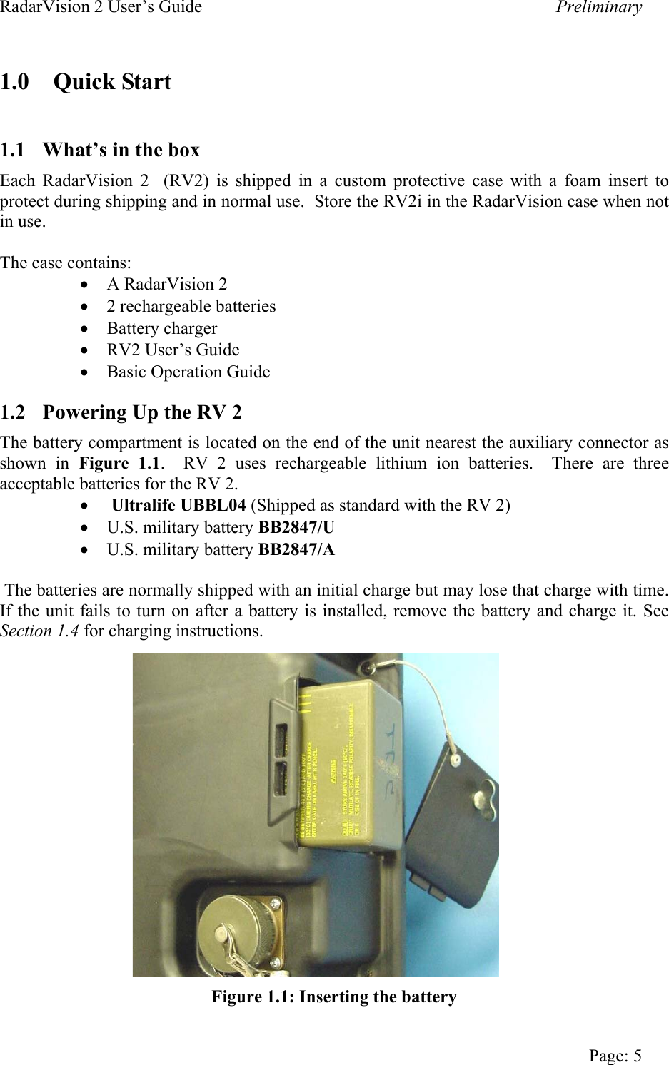
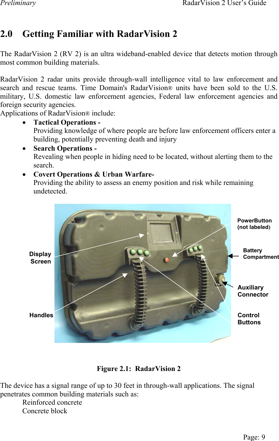
![RadarVision 2 User’s Guide Preliminary Sheetrock Brick Wood and wood composites Plaster Tile Fiberglass This manual will explain the basic features and functions of the device, describe the controls and options, provide tips for operation and give troubleshooting assistance. Figures 2.1 and 2.2 show the RV 2 from the operator’s side of the unit. The device is activated with a single Power On/Off [red] button. The green buttons aligned below and to either side of the display screen control other radar and display functions. When powered on the display screen shows objects detected by the radar. The auxiliary connector is used to perform diagnostics and software updates at the manufacturer, see Appendix A. 2.1 Overview of Controls The RV 2 powers up in scanning mode as shown in Figure 2.2. Button function descriptions appear in blue text on white bars. The unit must be powered on to view the menu function bars on the display screen. Each green function control button selects options for a corresponding function bar. The outermost, middle, and innermost control buttons operate the outermost, middle, and innermost display function bars respectively. Depress the corresponding green button to select an operation parameter. Options displayed on the six menu function bars may vary as you navigate the menu. Button Function Descriptions Menu Function Bars [White/Blue Text] Control Buttons [Green] Figure 2.2: Display and Function Control Buttons Page 10](https://usermanual.wiki/Humatics/RV2-0804.Section-1and-2/User-Guide-476072-Page-10.png)