Humatics RV2-0804 Through-Wall Radar User Manual Quick Start
TDC Acquisition Holdings Inc. Through-Wall Radar Quick Start
Humatics >
Contents
Section 1and 2

RadarVision 2™
User’s Guide
Preliminary
TDC Document 320-0098-A
Time Domain Corporation
Cummings Research Park
7057 Old Madison Pike Suite 250
Huntsville, AL 35806
Http://www.timedomain.com
RadarVision 2 User’s Guide Preliminary
Patent Protection
RadarVision 2®, RadarVision®2i™ and SoldierVision® are protected by U.S. and international issued and
pending patents, including but not limited to the following US patents: US 4743906; US 5363108; US 5812081;
US 6304623; US 6421389; US 6552677; US 6577691; US 6636573; US 6667724.
Trademarks and Copyright
Time Domain ®, RadarVision, SoldierVision and PulsON® are registered trademarks of Time Domain Corporation ©
2001-2004 Time Domain Corporation. All rights reserved.
Preservation of Time Domain Proprietary Rights
We own and retain all of our patents, trademarks, trade secrets, copyrights, designs, and other intellectual
property rights (“Proprietary Rights”). The third party manufacturers of any non Time Domain components of
the Product own and retain all of their Proprietary Rights in the component parts. Nothing in this Agreement is
intended to restrict the Proprietary Rights of any third party manufacturer or us. All intellectual property
developed, originated, or prepared by us in connection with providing to you the Products remain vested
exclusively in us, and this Agreement does not grant to you any shared development rights of intellectual
property.
Nothing in this Agreement will be deemed to grant, directly or by implication, estoppel, or otherwise, any right,
title or interest in our Proprietary Rights. You agree not to modify, disassemble, peel components, decompile,
otherwise reverse engineer or attempt to reverse engineer, derive source code or create derivative works from,
adapt, translate, merge with other software, reproduce, or export the Products or permit or encourage any third
party to do so.
Rights
Rights to use this documentation extends only to direct purchasers for training and operation of the RadarVision
unit. All other uses require prior written permission from Time Domain before this User’s Guide contents are
reproduced or used in full or in part.
Acceptance of Products
You accept the products ordered and these terms on the earlier of (1) two days after the date the products are
delivered to you or (2) the date you first use the products.
Limited Warranties and Disclaimer
Warranties are set forth in the warranty form(s) provided by us or referenced in the written Purchase Order, and
are incorporated by reference into these Terms and Conditions of Sale. No warranty is furnished for anything
excluded from the warranty form(s). These items are provided AS IS. EXCEPT AS PROVIDED ABOVE, NO
EXPRESS OR IMPLIED WARRANTIES, INCLUDING BUT NOT LIMITED TO IMPLIED WARRANTIES
OF MERCHANTABILITY OR FITNESS FOR A PARTICULAR PURPOSE, APPLY TO ANYTHING
PROVIDED BY US. We may use refurbished parts in new products as long as we use the same quality control
procedures and warranties as for new products.
Limitations of Remedies and Damages
THE TOTAL LIABILITY OF US AND OUR REPRESENTATIVES TO YOU AND YOUR EXCLUSIVE
REMEDY RELATING TO YOUR ORDER AND THE PRODUCTS ACQUIRED FROM US IS LIMITED TO
THE PRICE ACTUALLY PAID BY YOU TO US FOR THE PRODUCT OR SERVICE WHICH IS THE
BASIS FOR THE CLAIM. You agree that we and our representatives have no liability to you for (1) any
punitive, incidental or consequential damages, such as lost profit or revenue, (2) any assistance not required
under the applicable terms of sale, or (3) any claims related to your order which arise after the warranty period
Page: 2

Preliminary RadarVision 2 User’s Guide
ends. You will be barred from any remedy unless you give us prompt written notice of the problem complained
of. This is a commercial sales transaction. Any claim related to this contract will be covered solely by
commercial legal principles. We, our representatives, and you will have no tort liability to the other arising from
this contract. This limitation does not affect claims by third parties for personal injury due to our, our
representatives' or your negligence or product liability.
Indemnification
You agree to indemnify and hold us harmless from and against any and all damages, claims, liabilities and
expenses (including reasonable attorney’s fees) incurred by us (whether in settlement or otherwise) arising out
of or relating to your use of the Product, including without limitation third party claims against us arising from
your use of the Product, provided however that this indemnification shall not include matters arising out of or
related to product liability claims.
No Resale
Neither the Products nor any component(s) of the Products may be resold or otherwise transferred by you to
anyone else other than to your successor in interest by way of merger or sale of all or substantially all of your
assets.
Regulatory Notice
U.S. operation:
• This device complies with Part 15 of the FCC Rules. Operation is subject to the following two conditions:
(1) this device may not cause harmful interference, and (2) this device must accept any interference
received, including interference that may cause undesired operation.
• Parties operating this equipment must hold a license issued by the FCC to operate a transmitter in the
Public Safety Radio Pool under Part 90 of CFR Title 47. The license may be held by the organization for
which the UWB operator works on a paid or volunteer basis.
• Changes or modifications not expressly approved by Time Domain Corporation could void the user’s
authority to operate this equipment.
• FCC ID: NUF –RV2-0804
• Please consult with Time Domain Corp. if you have any questions, prior to use.
Export Notice
Pursuant to 22 CFR Chapter 1 paragraph 123.10 this item is not authorized for re-export, re-sales or other
disposition without prior written approval of the U.S. Government. Use outside the United States is restricted to
use by “Armed Forces” (i.e. Army, Navy, Marine, Air Force, Coast Guard, National Guard, National Police,
and any military unit or military personnel organized under or assigned to an international organization) or
approved security/law enforcement agencies.
Non-U.S. Operation
PulsON® technology has not been authorized for use or commercial exploitation under the regulations of any
non-U.S. government agency. Please confer with your government’s regulatory agency to obtain proper
authorizations.
Customer Support
Web: http://www.radarvision.com E-mail: customer.service@timedomain.com
Telephone: Armor Holdings RadarVision Support (904) 741 1754
Fax: (904) 741 6539
Page: 3
RadarVision 2 User’s Guide Preliminary
Table of Contents
Regulatory,Warranty and Conditions of Purchase .................................................................... 2
1.0 Quick Start ............................................................................................................................ 5
1.1 What’s in the Box............................................................................................................... 5
1.2 Powering Up the RV 2 ....................................................................................................... 5
1.3 Scanning ............................................................................................................................. 6
1.4 Charging the Batteries ........................................................................................................ 6
2.0 Getting Familiar with RadarVision 2 ................................................................................. 9
2.1 Overview of Controls............................................................................................................ 10
2.2 Overview of Display............................................................................................................. 11
2.3 Feet and Meters in Figures and Illustrations......................................................................... 13
3.0 Basic Features and Operation .............................................................................................. 15
3.1 Power On/Off ................................................................................................................... 15
3.2 Steadying the RadarVision 2 for Operation ..................................................................... 15
3.3 Scan Mode........................................................................................................................ 15
3.4 Display Options................................................................................................................ 16
3.5 CONTROLS Menu and Submenu.................................................................................... 16
3.5.1 Horizontal and Vertical Views .................................................................................. 16
3.5.2 Range......................................................................................................................... 16
3.5.3 Update Rate ............................................................................................................... 17
3.5.4 Motion and Static Object Detection .......................................................................... 17
3.5.5 Target Detection Sensitivity Settings ........................................................................ 19
3.6 Default Settings ................................................................................................................ 20
3.7 Battery Life (Charge and Change Out) ............................................................................ 21
3.8 Basic Handling Instructions and Specifications ............................................................... 21
4.0 Option and Control Descriptions ...................................................................................... 23
4.1 The Menu of Controls ...................................................................................................... 23
4.2 Return to the Scan Menu .................................................................................................. 24
4.3 Setup Menu: Performance Parameters ............................................................................. 25
4.3.1 SYMBOL Layer Controls ......................................................................................... 25
4.3.2 NOISE FILTER: Interference Rejection ................................................................... 26
4.3.3 BACKLIGHT Adjustment ........................................................................................ 29
4.3.4 TIMEOUT (Auto Shut-Down) .................................................................................. 29
4.3.5 CODEFILE................................................................................................................ 29
4.4 Blocked Wall Test ............................................................................................................ 30
4.5 CONTROLS Submenu..................................................................................................... 31
4.5.1 Horizontal vs. Vertical Views ................................................................................... 31
4.5.2 Range Options ........................................................................................................... 32
4.5.3 Display Update Rates ................................................................................................ 33
4.5.4 SENSITIVITY Controls (Motion and Static Layers) ................................................ 33
4.6 STANDBY Screen ........................................................................................................... 36
5.0 Tips for Operation .............................................................................................................. 39
5.1 Placing the Unit for Scanning........................................................................................... 39
5.2 RadarVision 2 Operational Settings ................................................................................. 39
5.3 Performance Optimizing Techniques............................................................................... 40
Appendix A: RV2 Specifications ................................................................................................ 47
Appendix B: RadarVision Product Warranty..................................................................49
Page 4
RadarVision 2 User’s Guide Preliminary
1.0 Quick Start
1.1 What’s in the box
Each RadarVision 2 (RV2) is shipped in a custom protective case with a foam insert to
protect during shipping and in normal use. Store the RV2i in the RadarVision case when not
in use.
The case contains:
• A RadarVision 2
• 2 rechargeable batteries
• Battery charger
• RV2 User’s Guide
• Basic Operation Guide
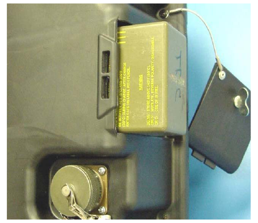
1.2 Powering Up the RV 2
The battery compartment is located on the end of the unit nearest the auxiliary connector as
shown in Figure 1.1. RV 2 uses rechargeable lithium ion batteries. There are three
acceptable batteries for the RV 2.
• Ultralife UBBL04 (Shipped as standard with the RV 2)
• U.S. military battery BB2847/U
• U.S. military battery BB2847/A
The batteries are normally shipped with an initial charge but may lose that charge with time.
If the unit fails to turn on after a battery is installed, remove the battery and charge it. See
Section 1.4 for charging instructions.
Figure 1.1: Inserting the battery
Page: 5
RadarVision 2 User’s Guide Preliminary
To insert or change batteries, twist the tabbed quarter-turn connector on the battery door
counter-clockwise, then swing the door open and disengage the tabs from the slots in the unit
casing. Insert the battery with the metal contacts innermost. Locking the cover is the reverse
process: engage the door tabs, then swing the door to spring-load the battery in its
compartment. Twist the quarter-turn connector clockwise to secure the door
Pushing the red button on the back (operator’s) side of the RV 2 will turn the unit on. It
takes about 10 seconds for the unit to boot and begin operating.
1.3 Scanning
The RV 2 will begin radar scanning when the boot up process is complete. No operator
action is needed to see radar information. A display with wedge-shaped reticle depicting the
radar’s field of view appears on the operator’s screen. This is a “top-down” view or map of
the target area being scanned. The operator and radar are located at the angled bottom of this
wedge shaped reticle. Targets farther away from the operator show up toward the top of the
reticle.
Also prominent are white bars with blue text on the lower sides of the screen. These bars are
the menu and each describe the functions of a corresponding green control button above the
left or right handles.
The radar will scan for moving targets immediately. These targets may appear as orange
“blobs” on the screen. Although there are controls to optimize the scanning image, no harm
can be done by using the radar and experimenting with it.
For further information on
• Overview of the RadarVision 2 and controls see Section 2.0.
• Basic operation and controls see Section 3.0.
• Detailed explanation and instructions on the control menu see Section 4.0.
1.4 Charging the Batteries
Batteries should be charged with the appropriate external charger applicable to the battery
model.. Use only the charger provided with the RV 2 to charge the Ultralife UBBL04
batteries. The battery cannot be charged while in the RV 2.
There are three parts to the charger:
• Standard three-prong socket (computer equipment) power cord.
• Power converter module with power cord that inserts into charge control
module.
• Charge control module with connector lead that plugs into the battery
The charge control module has an LED on the top which indicates the state of the charging
process.
• Off: No battery
• Green Flash: Fast charging
• Green Solid: Fully charged
Page 6
Preliminary RadarVision 2 User’s Guide
• Yellow Solid: Standby
• Red Flash: Error
If an error indication appears, unplug the battery from the control module. Unplug the control
module from the power converter. Reattach the power converter, then plug the control
module into the battery. If the red flashing light reappears, the battery may be faulty.
Contact RV 2 customer support. See the regulatory and conditions pages in the front of this
guide for contact information.
Page: 7
RadarVision 2 User’s Guide Preliminary
This page intentionally left blank
Page 8
Preliminary RadarVision 2 User’s Guide
2.0 Getting Familiar with RadarVision 2
The RadarVision 2 (RV 2) is an ultra wideband-enabled device that detects motion through
most common building materials.
RadarVision 2 radar units provide through-wall intelligence vital to law enforcement and
search and rescue teams. Time Domain's RadarVision® units have been sold to the U.S.
military, U.S. domestic law enforcement agencies, Federal law enforcement agencies and
foreign security agencies.
Applications of RadarVision® include:
• Tactical Operations -
Providing knowledge of where people are before law enforcement officers enter a
building, potentially preventing death and injury
• Search Operations -
Revealing when people in hiding need to be located, without alerting them to the
search.
• Covert Operations & Urban Warfare-
Providing the ability to assess an enemy position and risk while remaining
undetected.
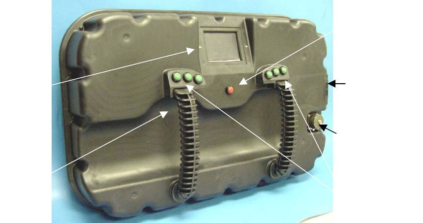
Auxiliary
Connector
Battery
Compartment
Control
Buttons
Displa
y
Screen
PowerButton
(not labeled)
Handles
Figure 2.1: RadarVision 2
The device has a signal range of up to 30 feet in through-wall applications. The signal
penetrates common building materials such as:
Reinforced concrete
Concrete block
Page: 9
RadarVision 2 User’s Guide Preliminary
Sheetrock
Brick
Wood and wood composites
Plaster
Tile
Fiberglass
This manual will explain the basic features and functions of the device, describe the controls
and options, provide tips for operation and give troubleshooting assistance.
Figures 2.1 and 2.2 show the RV 2 from the operator’s side of the unit. The device is
activated with a single Power On/Off [red] button. The green buttons aligned below and to
either side of the display screen control other radar and display functions. When powered on
the display screen shows objects detected by the radar. The auxiliary connector is used to
perform diagnostics and software updates at the manufacturer, see Appendix A.
2.1 Overview of Controls
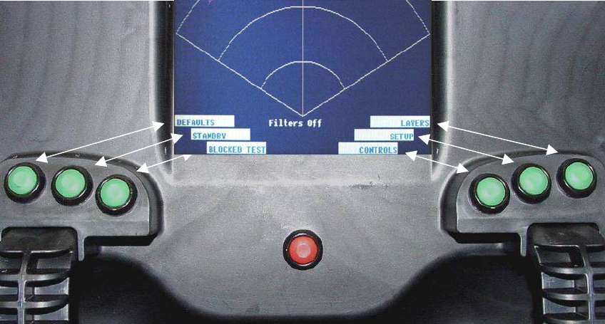
The RV 2 powers up in scanning mode as shown in Figure 2.2. Button function descriptions
appear in blue text on white bars. The unit must be powered on to view the menu function
bars on the display screen. Each green function control button selects options for a
corresponding function bar. The outermost, middle, and innermost control buttons operate
the outermost, middle, and innermost display function bars respectively. Depress the
corresponding green button to select an operation parameter. Options displayed on the six
menu function bars may vary as you navigate the menu.
Button
Function
Descriptions
Menu Function Bars
[White/Blue Text]
Control
Buttons
[Green]
Figure 2.2: Display and Function Control Buttons
Page 10
Preliminary RadarVision 2 User’s Guide
Text describing parameter options is displayed on the menu function bars. This text will
change depending on where one is in the menu structure. Choices are implemented with
either arrows or highlighting text centered between the function bars, see Figures 2.3, 2.4,
and 2.5. As the user adjusts various options, the new settings are immediately activated
within the radar. Only two parameters require the user specifically to accept the
modification in order to activate the selection: noise filter and codefile settings, see Sections
4.3.2 and 4.3.5 respectively.
With the exception of detection sensitivity, timeout, and symbol settings (Sections 4.5.4,
4.3.4, and 4.3.1), the unit will always power up with the option selections that were last
active when powered off. Users may save a particular set of option settings as described
Section 3.6.
Arrows indicate a choice
that can be toggled by
pressing the corresponding
green button.
FAST is active
SLOW is active
>>FST SLO FST >>SLO
Figure 2.3: Arrow Selection Indicators
Select + (plus) or –
(minus)to scroll through
range options. The option
selected will be highlighted
by a white box with dark
text.
3m / 5m / 10m / 20m --
+
5m
Figure 2.4: Option selection indicators
Symbol, Timeout, and
Codefile functions require
the user to select a number.
The number increment
readout is located beside
the + (plus) function label.
Codefile 9 --
+
Figure 2.5: Codefile Selection
2.2 Overview of Display
When the unit is in scanning mode, motion detection is displayed on a wedge shaped reticle
depicting a top-down field of view, see Figure 2.6 (next page). The radar scan originates at
the bottom or narrow end of the reticle and motion contacts are displayed with distance and
direction relative to the operator. This view is referred to as a horizontal view. A side-view,
or display of motion in the vertical plane relative to the radar, is also user selectable as
described in Section 3.4.1.
Page: 11
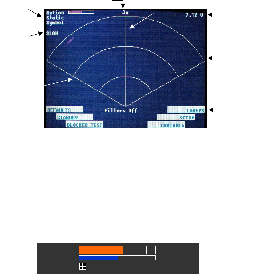
RadarVision 2 User’s Guide Preliminary
Boresi
g
ht line
Intermediate
range rings
Outer
range
ring
Screen
update
rate
Display
option
settings
Menu
function
bars
Battery
voltage
level
Maximum range
(User selectable)
Figure 2.6: RadarVision 2 Display
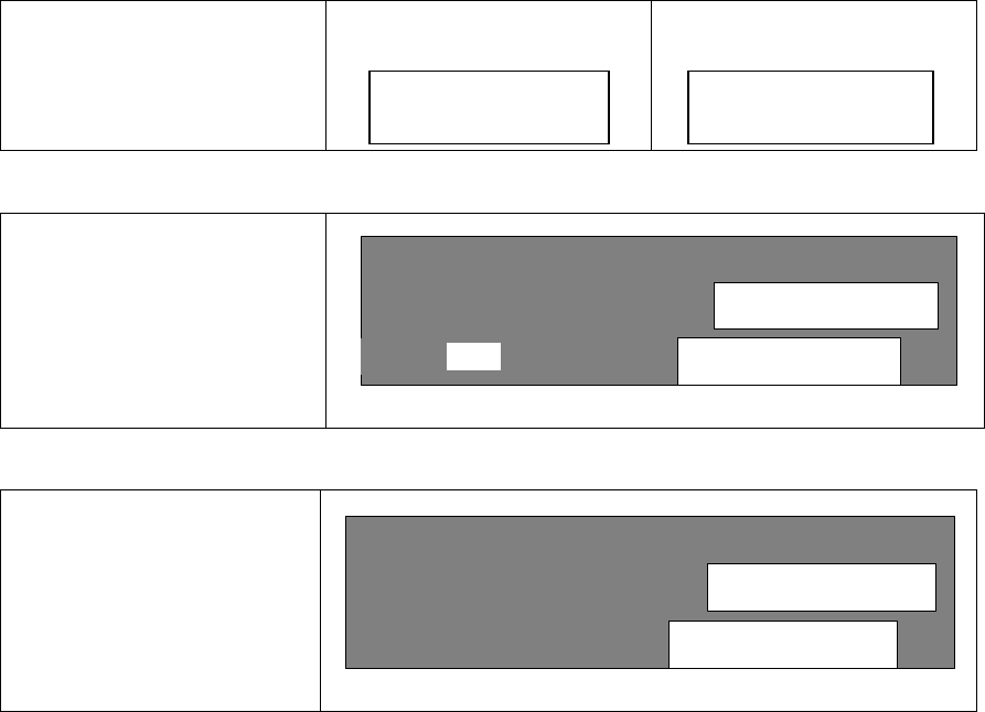
• Display option settings area (Figure 2.7) indicates which display options
(motion, static, and/or symbol) are active. Any combination of these options may
be selected or ‘layered’ upon one another for display viewing. Because of this
layering capability, when the radar is set for motion detection the ‘motion layer’ is
active. Likewise if the radar is set for static detection, the ‘static layer’ is active.
If a color bar appears next to the Motion and/or Static text this indicates that those
functions are active. A ‘+’ sign in a box next to the Symbol text indicates that
Symbol display is activated. The color bars also indicate sensitivity levels for
both Motion and Static displays These functions are selected and controlled with
green control buttons as discussed in Section 2.1. See Section 3.5.4 for more
information on these settings.
Motion
Static
Symbol
Motion
Static
Symbol
Motion
Static
Symbol
Figure 2.7: Display Option Indicators (Motion / Static / Symbol)
Note: Later models of RV 2 have a larger Motion bar than some earlier models. The
illustrations in this User Guide use both types interchangeably. There is no difference in the
function (described in Section 4.5.4) or in the other details of illustrations between the two
versions. The size was increased to aid the operator in reading sensitivity levels.
• Screen update rate is the rate at which the radar updates detection information to
the display. For more information on update rate see Section 3.4.3.
Page 12
Preliminary RadarVision 2 User’s Guide
• Maximum range indicates maximum distance for target detection and display.
This range is user selectable for distances of 9ft., 15ft., and 30ft. as defined in
Section 3.5.2.
• Boresight line indicates the center of the field of view.
• Voltage level is a real-time measurement of battery status. For more information
on battery life refer to Section 3.7.
• Range rings indicate intermediate distances for more accurate assessment of
motion location. The outer range ring represents the maximum range for the scale
selected. The inner range ring represents half that scale distance. On the very
short, 9 foot range, each intermediate range ring is one-third the distance.
• Menu function bars describe the functions of the six green control buttons. The
text contents of the bars change as the operator changes positions in the menu as
described in Section 4.0.
2.3 Feet and Meters in Figures an Illustrations
Linear measurement units for the RV 2 are indicated in feet. Some illustrations in this User
Guide show distance indicators in meters. These screen shots are from the RV 2i, which is
almost identical to the RV 2 but uses the metric measures. Range selection between the two
units is roughly equivalent, with 3 meter range equivalent to the 9 ft. range, the 5 meter range
equivalent to the 15 foot range and the 10 meter range equivalent to the 30 foot range.
Note: The RV2i screens used for illustration purposes show a 20m range option. RV 2 does
not offer this option and it does not appear on RV 2 screens.
Page: 13
RadarVision 2 User’s Guide Preliminary
Page 14
This page intentionally left blank