Users Manual

**
Thank you for purchasing a HUMAX IP Set-Top Box. Please read this user manual carefully, to be able to
safely install, use and maintain the product at maximum performance. Keep this user manual next to your
product for future reference.
**
Repairs and Warranty Service
**
Should your RG-200 require warranty service, please contact Humax first to obtain authorization. You can
reach us at 866.humax.usa,17501 Von Karman Avenue, Irvine, CA 92614, or by visiting our website at
http://www.humaxusa.com/support.html.
**
This product incorporates copyright protection technology that is protected by U.S. patents and other
intellectual property rights. Use of this copyright protection technology must be authorized by
Macrovision Corporation, and is intended for home and other limited consumer uses only unless
otherwise authorized by Macrovision. Reverse engineering or disassembly is prohibited.
**
Apparantus Claims of U.S. Patent Nos. 4,631,603; 4,577,216; 4,819,098 and 4,907,093 licensed for
limited viewing uses only.
**
Dolby and the double-D symbol are trademarks of Dolby Laboratories.
**
Manufactured under license from Dolby Laboratories.
**
All other trademarks are the properties of their respective owners.
**
Copyright © 2001- 2004 HUMAX Corporation
**
Not to be copied, used or translated in part or whole without HUMAX's prior consent in writing except approval
of ownership of copyright and copyright law.
**
The information in this document is subject to change without notice.
**
Notice
1
**
**
**
**
**
**
**
**
**
**
**
**
**
**
**
**
THIS SYMBOL IS INTENDED TO ALERT THE USER TO THE PRESENCE OF
UNINSULATED “DANGEROUS VOLTAGE” WITHIN THE PRODUCT’S ENCLOSURE THAT IS
OF SUFFICIENT MAGNITUDE TO CONSTITUTE A RISK OF ELECTRIC SHOCK TO
PERSONS.
**
THIS SYMBOL IS INTENDED TO ALERT THE USER TO THE PRESENCE OF IMPORTANT
OPERATING AND MAINTENANCE (SERVICING) INSTRUCTIONS IN THE LITERATURE
ACCOMPANYING THE DEVICE.
**
WARNING: TO REDUCE THE RISK OF FIRE OR ELECTRIC SHOCK. DO NOT
EXPOSE THIS DEVICE TO RAIN OR MOISTURE.
** • Read these instructions.
• Keep these instructions.
• Heed all warnings.
• Follow all instructions.
• Do not use this product near water.
• Clean only with dry cloth.
• Do not block any ventilation openings.
• Install in accordance with the manufacturer’s instructions.
• Do not install near any heat sources such as radiators, heat registers, stoves, or other products
(including amplifiers) that produce heat.
• Do not defeat the safety purpose of the polarized or grounding-type plug. A polarized plug has two
blades with one wider than the other. A grounding type plug has two blades and a third grounding
prong. The wide blade or the third prong is provided for your safety. If the provided plug does not fit into
your outlet, consult an electrician for replacement of the obsolete outlet.
• Protect the power cord from being walked on or pinched particularly at plugs, convenience receptacles,
and the point where they exit from the product.
• Use only attachments/accessories specified by the
manufacturer.
• Use this product only with the cart, stand, tripod, bracket, or
table specified by the manufacturer, or sold with the product.
When a cart is used, use caution when moving the cart/product
combination to avoid injury from tip-over
• Unplug this product during lightning storms or when unused for
long periods of time.
**
Important Information
2**
**
**
**
**
**
**
**
**
**
**
**
**
**

**• Refer all servicing to qualified service personnel. Servicing is required when the product has been
damaged in any way, such as power-supply cord or plug being damaged, exposure to liquid or
moisture, irregular operation, or has been dropped.
• The product should not be exposed to dripping or splashing liquids and that no objects filled with
liquids, such as vases, should be placed on the product.
**
This device complies with part 15 of the FCC Rules. Operation is subject to the following two
conditions:
**
(1) This device may not cause harmful interference, and
(2) This device must accept any interference that may cause undesired operation.
**
INFORMATION TO THE USER
This equipment has been tested and found to comply with the limits for a Class B digital device, pursuant to
part 15 of the FCC Rules. These limits are designed to provide reasonable protection against harmful
interference in a residential installation. This equipment generates, uses and can radiate radio frequency
energy and, if not installed and used in accordance with the instructions, may cause harmful interference to
radio communications. However, there is no guarantee that interference will not occur in a particular
installation. If this equipment does cause harmful interference to radio or television reception, which can be
determined by turning the equipment off and on, the user is encouraged to try to correct the interference by
one more of the following measures:
1. Reorient or relocate the receiving antenna.
2. Increase the separation between the equipment and product.
3. Connect the equipment into an outlet on a circuit different from that to which the product is connected.
4. Consult the dealer or an experienced radio/TV technician for help.
**
Caution:
• FCC regulations state that any unauthorized changes or modifications to this equipment may void the
user’s authority to operate it.
• RISK OF EXPLOSION IF BATTERY IS REPLACED BY AN INCORRECT TYPE. DISPOSE OF USED
BATTERIES ACCORDING TO THE INSTRUCTIONS.
**
**
3
**
**
**
**
**
**
**
**
**
**
**
**
**
**

**
1. Read Before Using the Product
1.1 Package Contents
1.2 Front Panel
1.3 Rear Panel
**
GB5
**
GB5
GB6
GB7
**
2. Setup
2.1 Connecting to LAN ports
2.2 Connecting to TV/VCR
2.3 Connecting to AV Receiver
2.4 Connecting to Antenna (optional)
2.5 Powering On
**
GB9
**
GB9
GB10
GB13
GB14
GB15
**
3. Troubleshooting
**
GB16
**
4. Specification GB17
**
Contents
4**
**
**
**
**
**
**
**
**
**
**
**
**
**
**
This chapter provides detailed instructions on the product and its accessories.
**
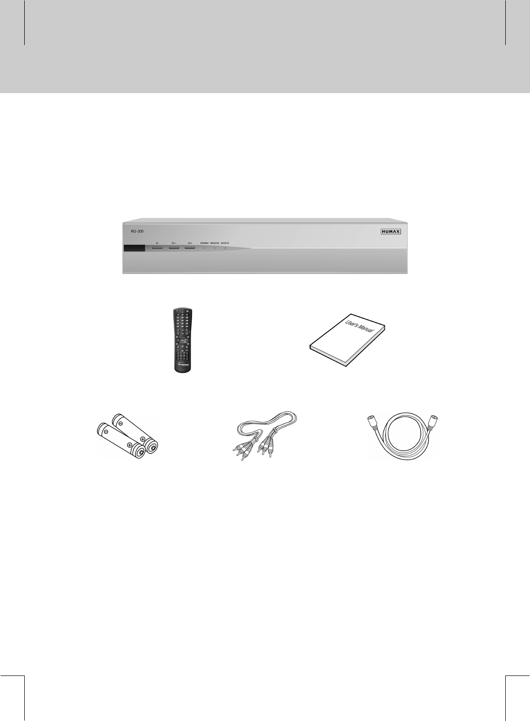
1.1 Package Contents
When you unpack your package contents, make sure you have all the necessary items shown in figure below.
If any of items is missing or damaged, please contact your product dealer for replacement.
**
**
Remote Controller User's Manual
**
Batteries RCA Cable RF Cable
**
1 Read Before Using This Product
5
**
**
**
**
**
**
**
**
**
**
**
**
**
**
**
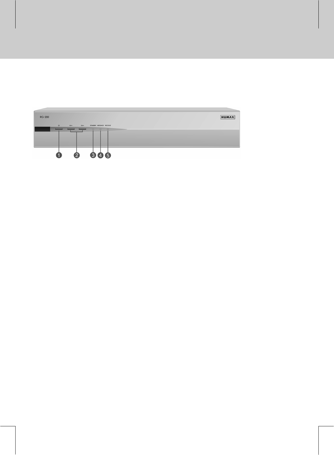
1.2 Front Panel
**
**
The following features are located on the front panel:
** 1. STANDBY Button
**
Switches between Operation and Standby modes.
**
2. CH- / CH+
**
Moves the TV channel up/down.
**
3. STANDBY LED
**
LED is green when STB is in Standby mode; LED is off in normal operating mode.
**
4. MESSAGE
**
The red LED is on when a message is present.
**
5. RECEIVE
**
The green LED flashes on momentarily each time a button press on the remote control or "CH- / CH+"
on the front panel is detected.
**
1 Read Before Using This Product
6**
**
**
**
**
**
**
**
**
**
**
**
**
**
**
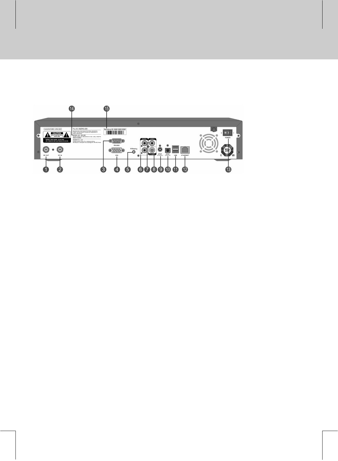
1.3 Rear Panel
**
**
The following features are located on the rear panel:
** 1. RF OUT
**
Connect this jack to ANTENNA IN jack on your TV or VCR.
**
2. RF IN
**
Connect an Aerial cable to this jack.
**
3. RS-232C
**
For future use only.
**
4. VGA
**
Connect this jack to VGA jack on Monitor, or other video equipment.
(Used for qualified technician only)
**
5. IR Blasting
**
Connect an IR Control cable to this jack.
**
6. AUDIO L/R
**
Connect this jack to AUDIO IN L/R jack on your TV or VCR using an RCA cable.
**
7. VIDEO
**
Connect this jack to VIDEO IN jack on your TV or VCR using an RCA cable.
**
8. S-VIDEO
**
Connect this jack to S-VIDEO IN jack on your TV or VCR using an S-Video cable.
**
**
**
7
**
**
**
**
**
**
**
**
**
**
**
**
**
**

**
1.3 Rear Panel
**
The following features are located on the rear panel:
** 9. S/PDIF (COAXIAL)
**
Connect this jack to COAXIAL IN jack on AV Receiver using a digital audio cable.
**
10. S/PDIF (OPTICAL)
**
Connect this jack to OPTICAL IN jack on AV Receiver using a digital audio cable.
**
11. USB
**
Connect this jack to USB jack on external equipment.
**
12. ETHERNET
**
Connect this to LAN ports.
**
13. ON/OFF
**
Power On and Off.
**
14. Model Number Label
**
15. Serial Number Label
**
1 Read Before Using This Product
8**
**
**
**
**
**
**
**
**
**
**
**
**
**
**
This chapter describes how to set up the product. Before you connect the product to any other equipment, you
must disconnect all the equipment from their power sources.
**
Follow this step procedure:
1. Connect the product to your home network.
2. Connect the product to a TV and other devices.
3. If necessary, connect an Aerial to the product through RF-Input.
4. Plug the product in and turn it on. Enjoy web browsing, e-mail, and other services.
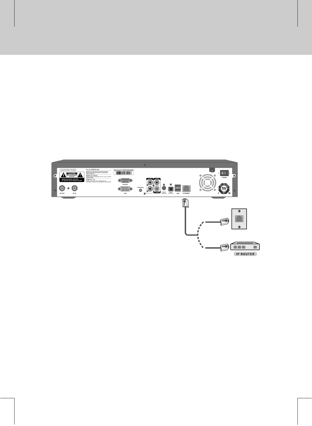
2.1 Connecting to LAN ports
**
**
Connect Ethernet port on the product to the LAN port on the wall outlet or through IP router using an RJ-45
network cable (not included).
**
2 Setup
9
**
**
**
**
**
**
**
**
**
**
**
**
**
**
**
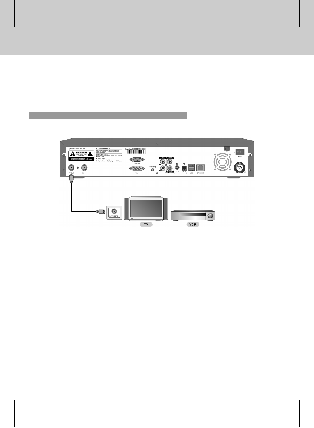
2.2 Connecting to TV/VCR
Select the most appropriate procedure depending on your situation.
**
1. RF Cable
**
**
Connect RF OUT jack on the product to ANTENNA IN jack on the TV/VCR using the RF cable.
Note: Tune TV to channel [preset channel #].
**
2 Setup
10 **
**
**
**
**
**
**
**
**
**
**
**
**
**
**
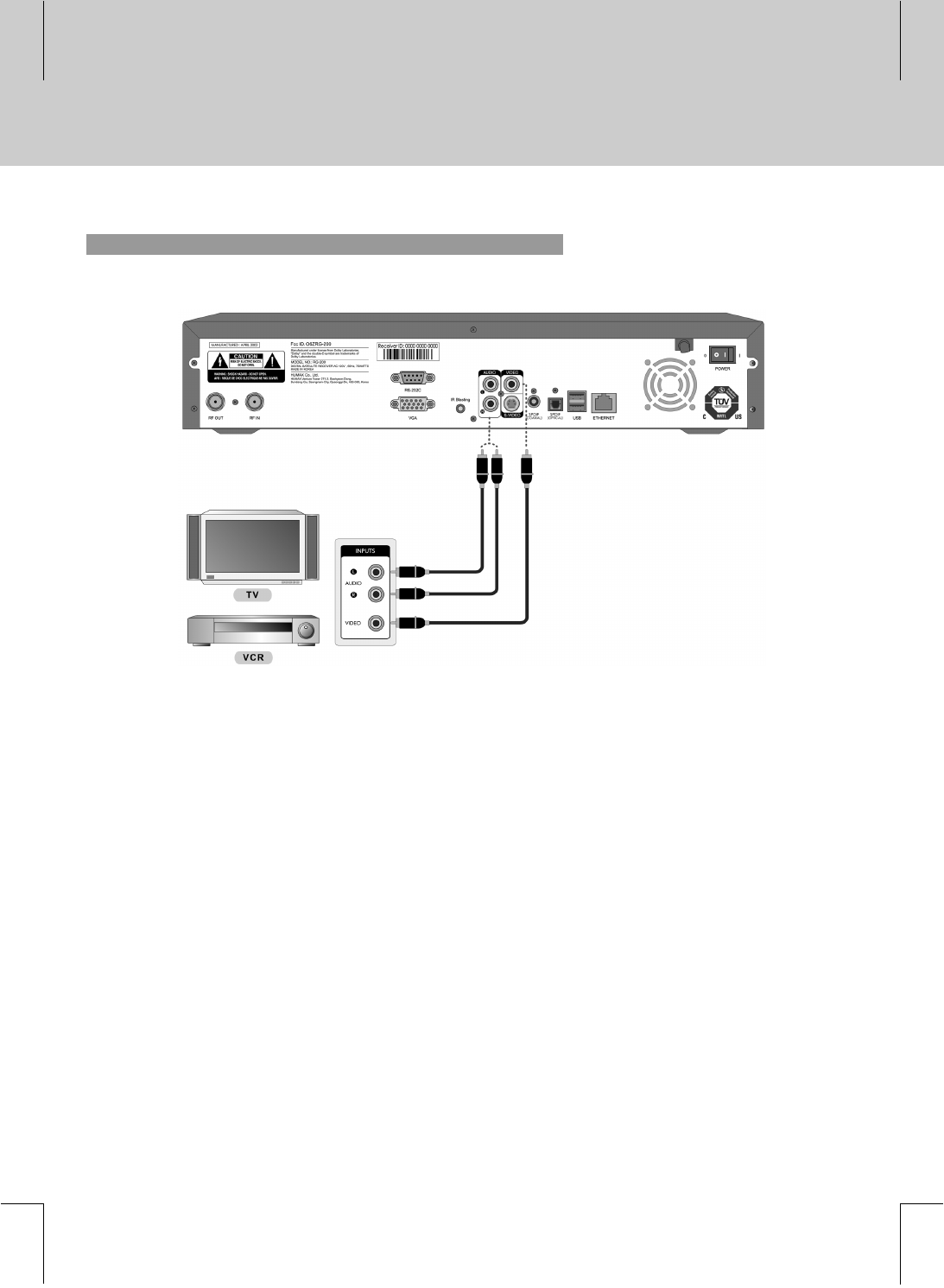
2. VIDEO Cable
**
**1. Connect VIDEO jack on the product to VIDEO IN jack on the TV/VCR using the RCA cable.
2. Connect AUDIO L/R jack on the product to AUDIO IN L/R jack on the TV/VCR using the RCA cable.
**
**
11
**
**
**
**
**
**
**
**
**
**
**
**
**
**
**
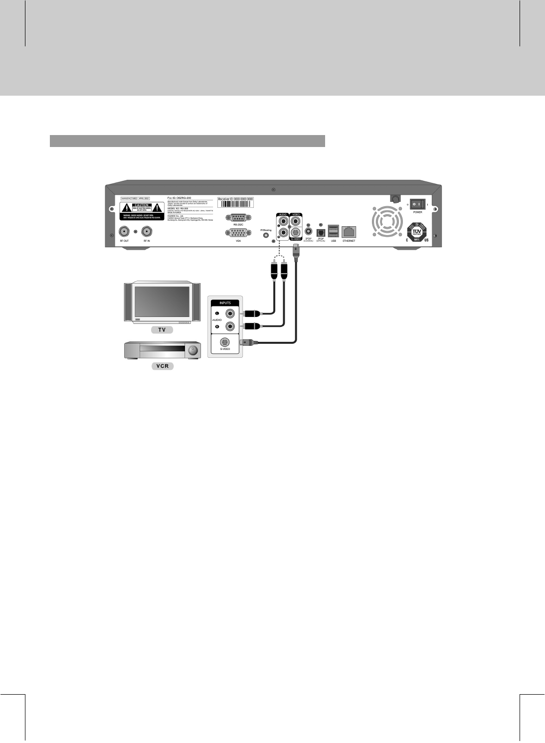
3. S-VIDEO Cable
**
**1. Connect S-VIDEO jack on the product to S-VIDEO IN jack on the TV/VCR using a S-VIDEO cable(not
included).
2. Connect AUDIO L/R jack on the product to AUDIO IN L/R jack on the TV/VCR using the RCA cable.
**
2 Setup
12 **
**
**
**
**
**
**
**
**
**
**
**
**
**
**
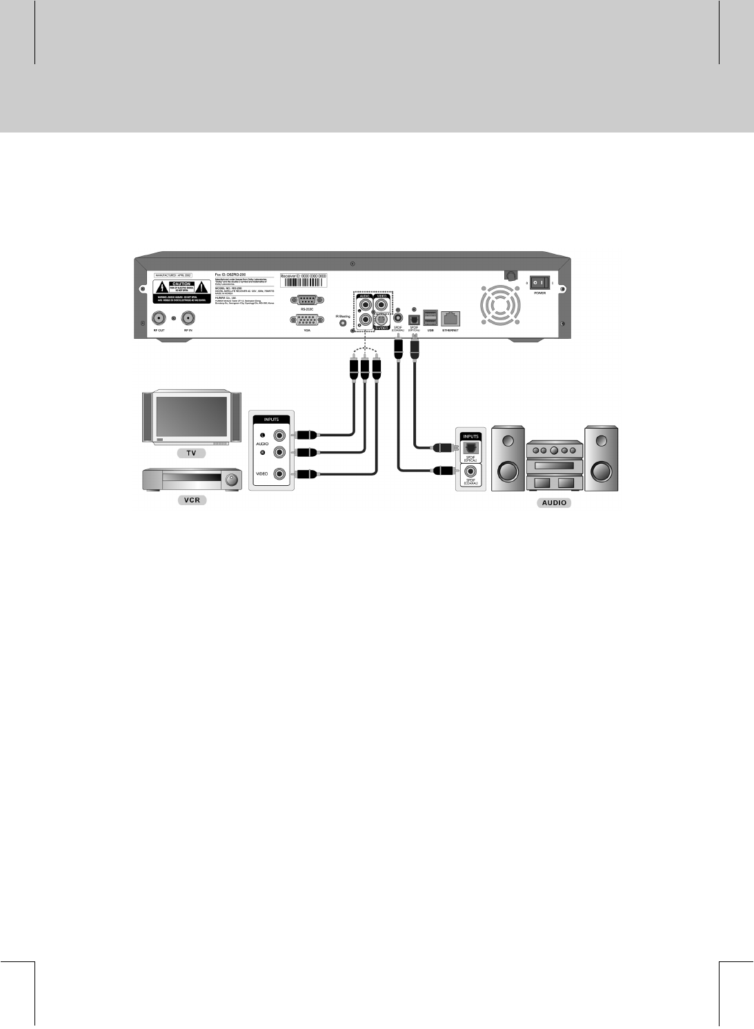
2.3 Connecting to AV Receiver
**
**1. Connect S/PDIF(OPTICAL) jack on the product to OPTICAL IN jack on the AV Receiver using a digital
audio cable(not included). (Optional)
2. Connect S/PDIF(COAXIAL) jack on the product to COAXIAL IN jack on the AV Receiver using a digital
audio cable(not included). (Optional)
3. Connect AUDIO L/R jack on the product to AUDIO IN L/R jack on the TV/VCR using the RCA cable.
4. Connect VIDEO jack on the product to VIDEO IN jack on the TV/VCR using the RCA cable.
**
**
13
**
**
**
**
**
**
**
**
**
**
**
**
**
**
**
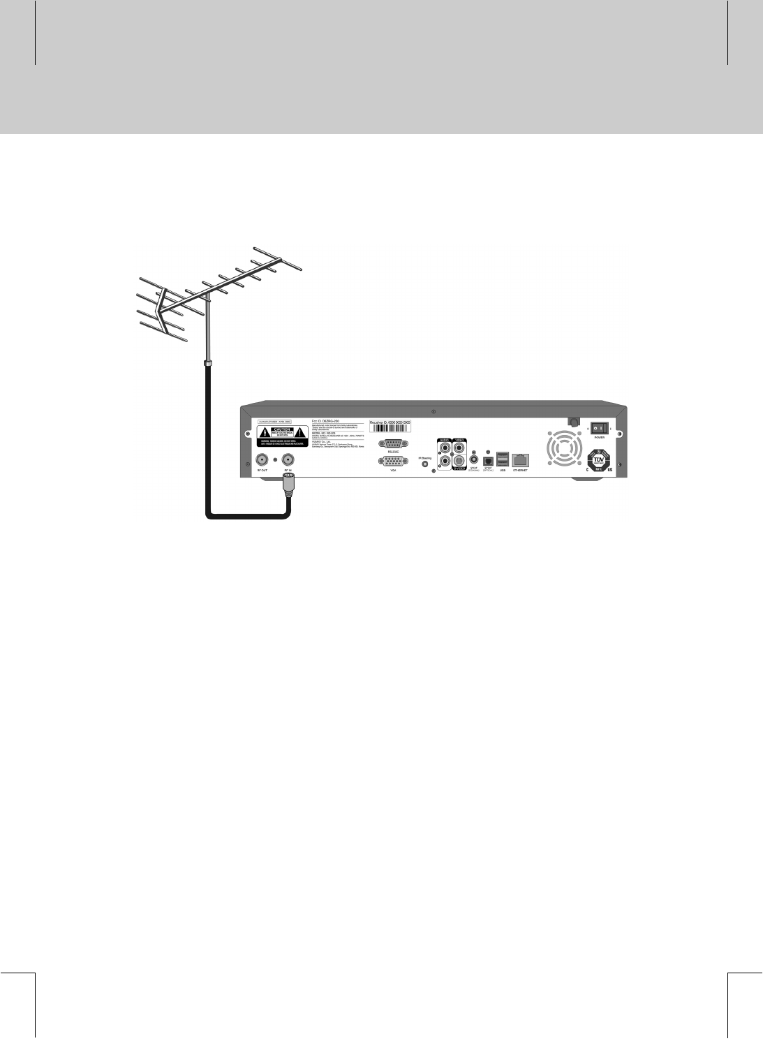
2.4 Connecting to Antenna (optional)
**
**
Connect an Aerial to RF IN jack on the product.
**
2 Setup
14 **
**
**
**
**
**
**
**
**
**
**
**
**
**
**
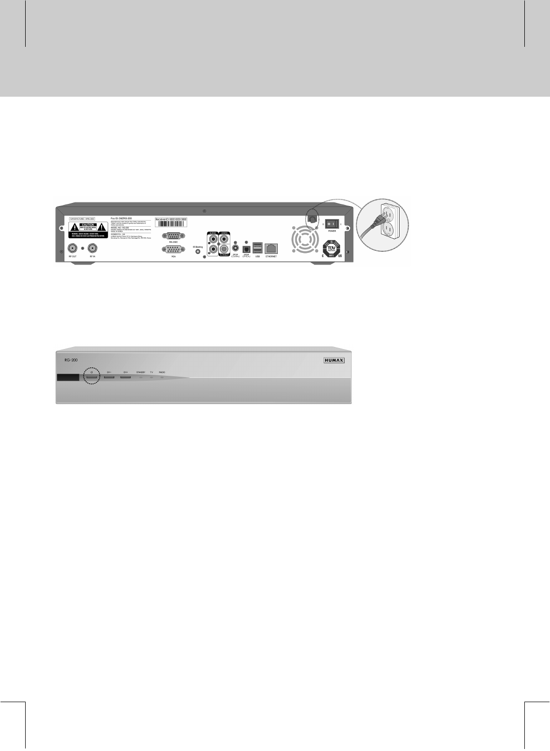
2.5 Powering On
**
1. Connect the product’s power cord to a wall outlet.
**
**
2. Turn on the power switch on the rear panel.
**
3. Press the STANDBY button either on the front panel or on the remote controller.
**
**
**
15
**
**
**
**
**
**
**
**
**
**
**
**
**
**

**
Please read the following instructions, before contacting your local service office. If the product does not work
normally after completing the following troubleshooting, please contact your local product distributor or service
center.
** 1. The LED on the front panel does not illuminate.
- Make sure that the main power cable is plugged into a suitable power outlet.
**
2. No picture
- Make sure that the product is in operation.
- Make sure that the AV Cable is firmly connected to the TV.
- Make sure that the antenna line is correctly connected to the equipment.
- Check the brightness level on TV.
- Make sure the LAN cable is correctly connected to LAN port.
- Make sure the TV channel is on air.
**
3. Poor picture & sound quality
- Make sure there is no mobile phone or microwave oven near the equipment.
**
4. No sound or poor sound
- Check the volume level of your TV and product.
- Make sure that Mute is not active on your TV and product.
**
5. Remote controller does not operate
- Make sure the remote control is pointing directly at the product. The emitter on the controller must
have an unobstructed path to the receiver on the product.
- Check the battery of the remote controller.
**
3 Troubleshooting
16 **
**
**
**
**
**
**
**
**
**
**
**
**
**
**
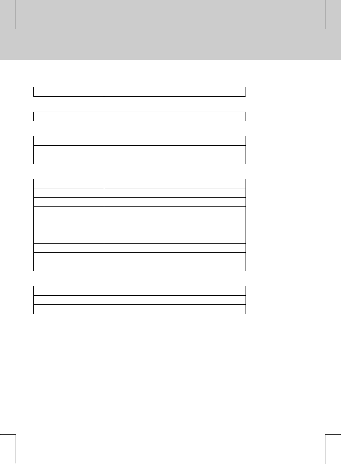
Network Interface
Ethernet 1 RJ-45 port, 10/100Base-T Ethernet
**
OS
WinCE.Net 5.0 Net Compact Framework V1.0
**
A/V Decoding
Video MPEG 1, MPEG 2
Audio MPEG 1 (including MP3), WMA
AC3 (Down mix to 2 channels, Bypass)
**
A/V & Data In/Out
Ethernet 1 RJ-45 port
USB port 2 ports V2.0 High-Speed
RS-232C 1 port
RF Modulator 1 port NTSC Modulator
Composite Video Out 1 port
S-Video 1 port
VGA port 1 port Standard VGA connector
S/PDIF 1 port Optical Port & 1 port Coaxial Port
Stereo Channels 2 ports (Right/Left)
IR Blasting Port 1 port CIR protocol
**
Front Panel
Front Key 3 buttons
Front LED 3 LED's
IR Receiver 1 port
**
4 Specifications
17
**
**
**
**
**
**
**
**
**
**
**
**
**
**
**
Input Device
Remote controller
Wireless Keyboard Optional
**
Mass Storage
HDD 80GB (Server Type)
CF Memory 64MB (Client Type)
**
Power Supply
Input Voltage 110 VAC
Type SMPS
Power Consumption 52W (w/HDD) / 32W (w/oHDD)
**
Physical Specification
Size (W x H x D) 420 x 75 x 300(mm)
Weight 4.5Kg (w/ HDD) / 3.5Kg (w/o HDD)
**
Note: Specifications and functions may be changed for improvement without notice in advance.
**
4 Specifications
18 **
**
**
**
**
**
**
**
**
**
**
**
**
**