Hunter Fan TX14 Ceiling fan and lamp remote control. User Manual 41462 01 remote no light USA p65
Hunter Fan Company Ceiling fan and lamp remote control. 41462 01 remote no light USA p65
Users Manual
20 41462-01 04/06/01
®
STEP 9 - REMOTE CONTROL
SETTING UNIQUE DIP SWITCH
NUMBERS
IMPORTANT: Before using this con-
trol, change the factory default DIP
switch settings on the Remote and
the Fan, to your own unique code.
Refer to Figure 9a, 9b and 9c.
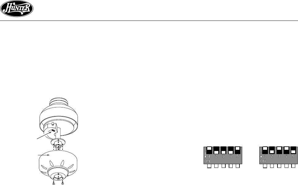
Figure 9a
Dip Switch
Motor Cover
Note: All fans leave the factory set to
‘01110’.
Note: If this is the second fan in-
stalled in the same area, one of the
fans MUST have its channel changed
from ‘01110’ or interference will oc-
cur. Make sure that the dip switch
settings in both the second remote
and second fan are set to the same
different numbers.
CHECKING FAN SETTING
1. Remove the three motor cover
screws and lift the motor cover
off.
2. Through the view hole on top of
the motor, locate the dip switch.
Refer to Figure 9a.
3. Check that the dip switch in the
fan and the remote are set to the
same unique numbers.
4. Replace the cover and screws.
SETTING UNIQUE DIP SWITCH
NUMBERS
By changing the sliding switches on
the fan and remote DIP switches,
many combinations of unique num-
bers can be selected. Refer to Fig-
ure 9b. On = 0 and off = 1.
DIP Switch
Set to
01110
DIP Switch
Set to
01001
Figure 9b
21
41462-01 04/06/01
®
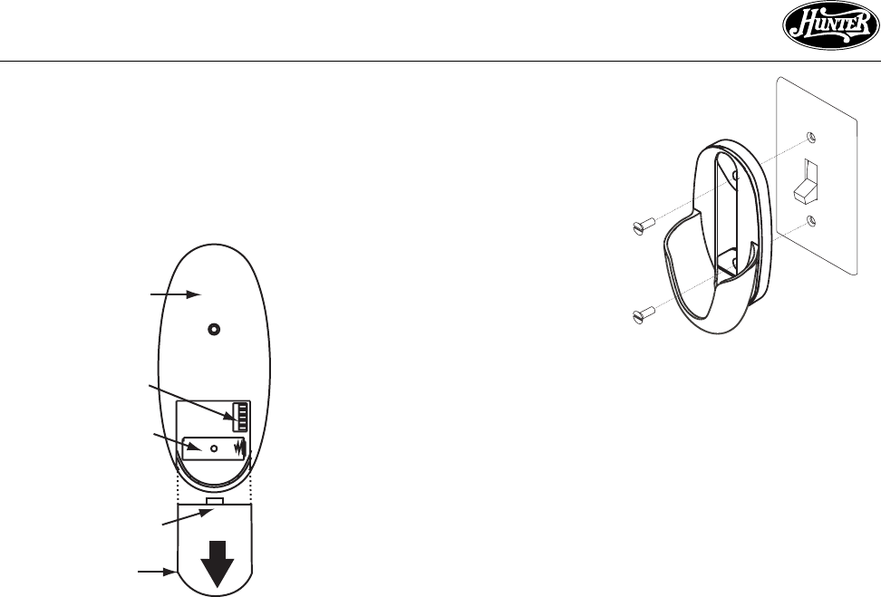
See Figures 9a, 9b, and 9c. The
battery must be removed when
changing dip switch settings.
Install the included 12 volt alka-
line battery (Type 23A, MN-21 or
equivalent) inside the remote
matching polarity on the Battery
as indicated by the + and - sym-
bols in the Battery Compartment.
See Figure 9c.
REMOTE CRADLE INSTALLATION
STANDARD LIGHT SWITCH
1. Remove the two screws holding
the switch cover plate. Do not re-
move the cover plate.
2. Orient the control cradle as
shown in Figure 9d, and line up
the two inner mounting holes
with those on the switch, insert
screws, don't over tighten.
REMOTE SETUP
1. Slide the cover off the back of the
remote as shown in Figure 9c,
pressing in and sliding the cover
down to release. Set the DIP
switches in the Remote to match
the DIP switches in the receiver.
continued
Figure 9d
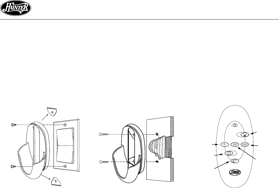
ROCKER LIGHT SWITCH
1. Break off the two tabs by push-
ing outward. See Figure 9e.
2. Remove the two screws holding
the switch cover plate. Do not re-
move the cover plate.
3. Orient the remote cradle as
shown in Figure 9e. Line up the
two outer mounting holes with
Figure 9c
DIP Switches
Battery Compartment
Cover
Back of Remote
Press Cover
Here and
Slide Down
22 41462-01 04/06/01
®
Fan
Low
Reverse
Fan Off Fan
Medium
Fan High
Figure 9e
those on the switch , insert
screws, don't over tighten.
WALL INSTALLATION
1. Locate a 2x4 wall stud in a conve-
nient location.
2. Orient the remote cradle as shown
in Figure 9f, over the 2x4 stud.
3. Use the 1” wood screws in either
the inner or outer mounting holes.
Note: Wall anchors and 6-32 x 1”
screws may be used in situations
where mounting to a stud is not pos-
sible. Use the inner mounting holes.
Remove
Tab
Remove
Tab Figure 9g
Figure 9f
FAN CONTROL
Refer to Figure 9g for identification
of control buttons.
To start the fan. Press the selected
speed button to run the fan at the
desired speed. See Figure 9g.
Optional
Light
AIRFLOW DIRECTION
To reverse the airflow press the RE-
VERSE button. Reverse operates at
any speed whether fan is on or off.
The fan returns to its set speed after
reversing.
23
41462-01 04/06/01
®
off and on, the user is encouraged
to try to correct the interference by
one or more of the following mea-
sures:
• Reorient or relocate the receiving
antenna.
• Increase the separation between
the equipment and receiver.
• Connect the equipment into an
outlet on a circuit different from
that to which the receiver is con-
nected.
• Consult the dealer or an experi-
enced radio/TV technician for help.
Note: Any changes or modifica-
tions to the transmitter or receiver
not expressly approved by Hunter
Fan Company may void one’s au-
thority to operate this remote con-
trol.
3. For use only with electrically re-
versible ceiling fans rated at 1.0
amp or less, and fan incandescent
light kits rated at 300 watts or less.
4. Not for use with shaded-pole or
nonreversible motors. Not recom-
mended for use with the Hunter
Original ®.
FCC INFORMATION
1. This device complies with Part 15 of
the FCC Rules. Operation is subject
to the following two conditions: (1)
This device may not cause harmful
interference, and (2) this device
must accept any interference re-
ceived, including interference that
may cause undesired operation.
2. This equipment has been tested
and found to comply with the lim-
its for a Class B digital device, pur-
suant to Part 15 of the FCC Rules.
These limits are designed to provide
reasonable protection against
harmful interference in a residen-
tial installation. This equipment
generates, uses and can radiate ra-
dio frequency energy and, if not in-
stalled and used in accordance with
the instructions, may cause harm-
ful interference to radio communi-
cations. However, there is no guar-
antee that interference will not oc-
cur in a particular installation.
If this equipment does cause harm-
ful interference to radio or televi-
sion reception, which can be deter-
mined by turning the equipment
OPTIONAL LIGHT CONTROL
Turn the light on or off indepen-
dently from the fan by pressing the
LIGHT button. Keep pressing the
button in excess of 1 second, it be-
comes a dimmer. The light varies
from ‘bright’ to ‘dim’ over approxi-
mately 8 seconds. This sequence will
reverse the light when it reaches the
brightest or dimmest level if you con-
tinue to hold the LIGHT button. Re-
lease the button when the desired
level is reached.
AUTO RESUME
Quick (pressing less than 1 second)
on/off operation of the LIGHT but-
ton maintains the desired brightness
level set previously.