Hunter Fan TX19 Remote Control for Ceiling Fan/Lamp User Manual 41874 01 rev 05 28 04 indd
Hunter Fan Company Remote Control for Ceiling Fan/Lamp 41874 01 rev 05 28 04 indd
Contents
- 1. Users manual
- 2. users manual
Users manual

2
Hunter Fan Company 41874-01 • 11/03/04
3
41874-01 • 05/28/04 Hunter Fan Company
Your new Hunter® ceiling fan is an addition to your home or oce that
will provide comfort and performance for many years. is installation
and operation manual gives you complete instructions for installing
and operating your fan.
We are proud of our work. We appreciate the opportunity to supply
you with the best ceiling fan available anywhere in the world.
Before installing your fan, for your records and warranty assistance,
record information from the carton and Hunter nameplate label
(located on the top of the fan motor housing).
Cautions and Warnings
• Read this entire manual carefully before beginning installation. Save
these instructions.
• Use only Hunter replacement parts.
• To reduce the risk of personal injury, attach the fan directly to the
support structure of the building according to these instructions,
and use only the hardware supplied.
• To avoid possible electrical shock, before installing your fan,
disconnect the power by turning o the circuit breakers to the
outlet box and associated wall switch location. If you cannot lock
the circuit breakers in the o position, securely fasten a prominent
warning device, such as a tag, to the service panel.
• All wiring must be in accordance with national and local electrical
codes and ANSI/NFPA 70. If you are unfamiliar with wiring, use a
qualied electrician.
• To reduce the risk of personal injury, do not bend the blade
attachment system when installing, balancing, or cleaning the fan.
Never insert foreign objects between rotating fan blades.
• To reduce the risk of re, electrical shock, or motor damage, do not
use a solid-state speed control with this fan. Use only Hunter speed
controls.
For Your Records and Warranty
Assistance
Model Name: _____________________
Catalog/Model No.: ________________
Serial No.: _______________________
Date Purchased: ___________________
Where Purchased: _________________
For reference also attach your receipt or a
copy of your receipt to the manual.
Table of Contents
1 • Getting Ready ...................................................4
2 • Installing the Ceiling Plate..........................5
3 • Assembling and Hanging the Fan..........6
4 • Wiring the Fan..................................................7
5 • Installing the Canopy and Canopy
Trim Ring..............................................................8
6 • Assembling the Blades.................................9
7 • Installing the Light Kit............................... 10
8 • Assembling the Remote Control
and Mounting the Cradle....................... 12
9 • Operating and Cleaning
Your Ceiling Fan ........................................... 14
10 • Troubleshooting......................................... 16
Welcome
© 2004 Hunter Fan Company
2
Hunter Fan Company 41874-01 • 05/28/04
3
41874-01 • 11/03/04 Hunter Fan Company
Mounting and Optional Accessories
Understanding Mounting
Hunter’s patented mounting system provides you maximum
installation exibility and ease. You can install your Hunter fan in
one of two ways, depending on your preference: Standard or Angle
mounting. e steps in this manual include instructions for both
mounting methods.
Considering Optional Accessories
Consider using Hunter’s optional accessories, including a wall-mounted
or remote speed control. To install and use the accessories, follow
the instructions included with each product. For quiet and optimum
performance of your Hunter fan, use only Hunter speed controls.
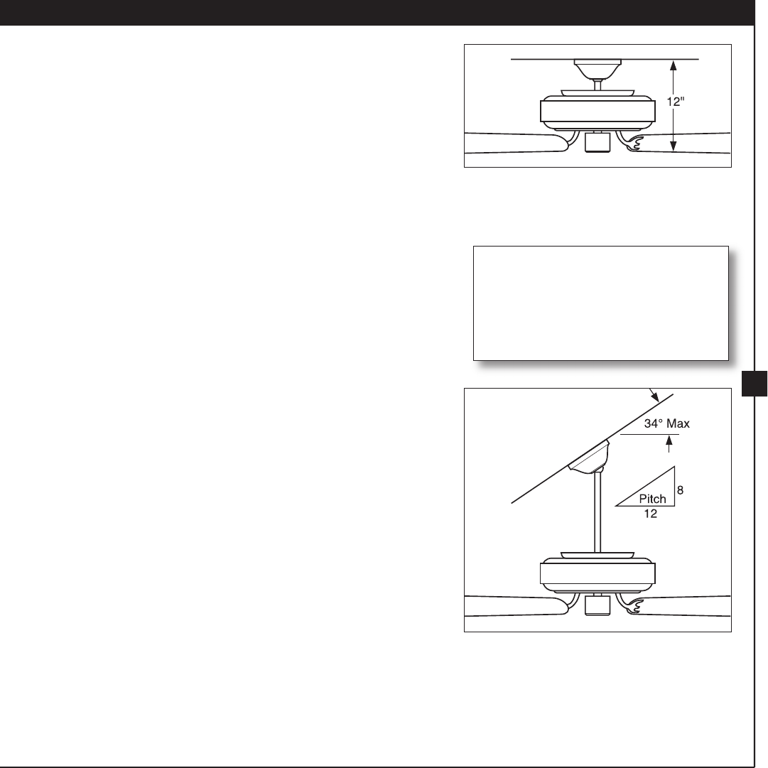
Standard Mounting hangs from
the ceiling by a downrod (included),
recommended for ceilings 8 feet or higher
Angle Mounting recommended for a
vaulted or angled ceiling
For ceilings higher than 8 feet, you
can purchase Hunter extension
downrods. All Hunter fans use sturdy
3/4” diameter pipe to assure stability
and wobble-free performance.
4
Hunter Fan Company 41874-01 • 11/03/04
5
41874-01 • 05/28/04 Hunter Fan Company
To install a ceiling fan, be sure you can do the following:
• Locate the ceiling joist or other suitable support in ceiling.
• Drill holes for and install wood screws.
• Identify and connect electrical wires.
• Lift 40 pounds.
If you need help installing the fan, your Hunter fan dealer can direct
you to a licensed installer or electrician.
Gathering the Tools
You will need the following tools for installing the fan:
• Electric drill with 9/64” bit
• Standard screwdriver
• Phillips-head screwdriver
• Wrench or pliers
Checking Your Fan Parts
Carefully unpack your fan to avoid damage to the fan parts. Check
for any shipping damage to the motor or fan blades. If one of the fan
blades was damaged in shipment, return all the blades for replacement.
If any parts are missing or damaged, contact your Hunter dealer or call
Hunter Parts Department at 888-830-1326.
Preparing the Fan Site
Before you begin installing the fan, follow all the instructions in
the pullout sheet called “Preparing the Fan Site.” Proper ceiling fan
location and attachment to the building structure are essential for
safety, reliable operation, maximum e ciency, and energy savings.
1 • Getting Ready
Installing Multiple Fans?
If you are installing more than
one fan, keep the fan blades in
sets, as they were shipped.
4
Hunter Fan Company 41874-01 • 05/28/04
5
41874-01 • 11/03/04 Hunter Fan Company
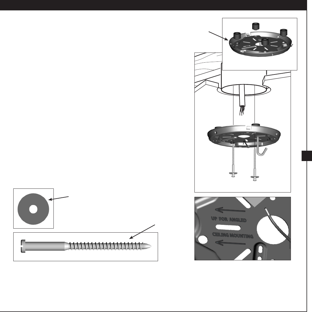
2-1. Drill two pilot holes into the wood support structure through the
outermost holes in the outlet box. e pilot holes should be 9/64”
in diameter.
2-2. Your fan comes with four neoprene noise isolators (“Isolators”).
Position the isolators between the ceiling plate and ceiling by
inserting the raised areas on each isolator into the holes in the
ceiling plate.
2-3. read the lead wires from the outlet box down through the hole
in the middle of the ceiling plate.
2-4. Align the slotted holes in the ceiling plate with the pilot holes you
drilled in the wood support structure. For proper alignment use
slotted holes directly across from each other.
Note: e isolators should be ush against the ceiling.
2-5. Place a at washer on each of the two 3” screws and pass the
screws through the slotted holes in the ceiling plate into the pilot
holes you drilled.
Tighten the screws into the 9/64” pilot holes; do not use lubricants
on the screws. Do not over tighten.
Step 2-2
Flat Washer
3” Screw
Steps 2-3 – 2-5
2 • Installing the Ceiling Plate
For Angled Ceilings: Be sure to
orient the ceiling plate so that the
arrows printed on the ceiling plate are
pointing towards the ceiling peak.
Ceiling
Plate
6
Hunter Fan Company 41874-01 • 11/03/04
7
41874-01 • 05/28/04 Hunter Fan Company
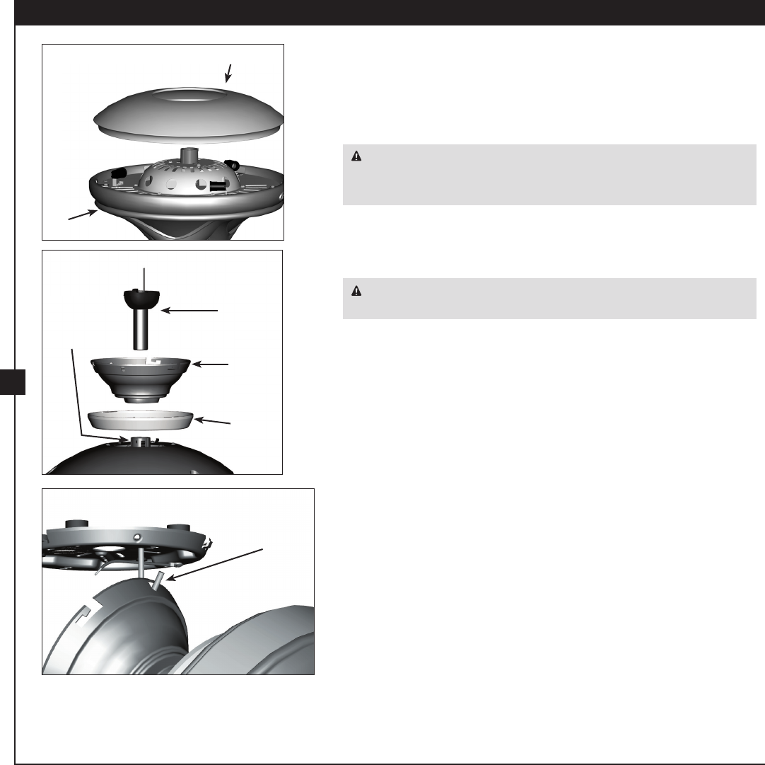
3-1. Install three 25 Watt Candelabra bulbs.
3-2. Place the glass uplight onto the fan assembly.
3-3. Insert the downrod through the canopy, canopy trim ring, and
glass uplight. Feed the wires from the fan through the downrod.
CAUTION: e downrod has a special coating on the threads.
Do not remove this coating; the coating prevents the downrod from
unscrewing. Once assembled, do not remove the downrod.
3-4. Screw the downrod into the fan assembly. Tighten the set screw.
3-5. Raise the fan and place the hook on the ceiling plate through the
U-shaped hole in the rim of the canopy.
WARNING: Fan may fall if not assembled as directed in these
installation instructions.
3 • Assembling and Hanging the Fan
Downrod
Canopy
Canopy
Trim Ring
Set Screw
Step 3-2 Glass Uplight
Fan
Assembly
Step 3-3
Step 3-5
U-shaped
Hole
6
Hunter Fan Company 41874-01 • 05/28/04
7
41874-01 •11/03/04 Hunter Fan Company
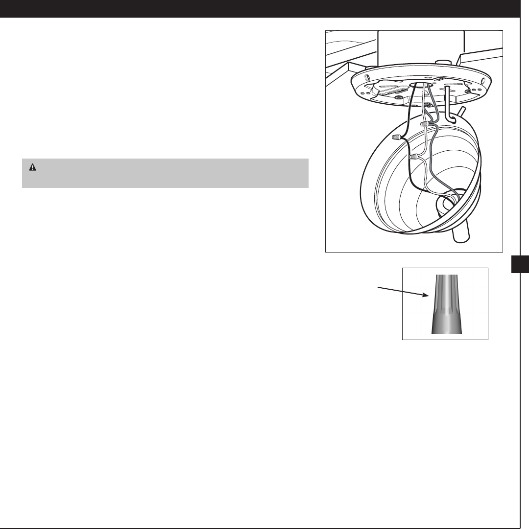
Wire Nut
All wiring must be in accordance with national and local electrical
codes and ANSI/NFPA 70. If you are unfamiliar with wiring, use a
qualied electrician.
4-1. Disconnect the power by turning o the circuit breakers to the
outlet box and associated wall switch location.
4-2. To connect the wires, hold the bare metal leads together and place
a wire nut over them, then twist clockwise until tight. For all these
connections use the larger wire nuts provided.
CAUTION: Be sure no bare wire or wire strands are visible after
making connections.
4-3. Connect the wires as follows:
• e ground wire from the ceiling to the green ground wire
from the ceiling plate and the green ground wire
• e white (common) power wire from the ceiling to the longer
white wire
• e black power wire from the ceiling to the longer black wire
4-4. Push all wires and wire nuts back through the ceiling plate hole
into the outlet box.
4 • Wiring the Fan
Steps 4-2 – 4-3
8
Hunter Fan Company 41874-01 • 11/03/04
9
41874-01 • 05/28/04 Hunter Fan Company
5 • Installing the Canopy and Canopy Trim Ring
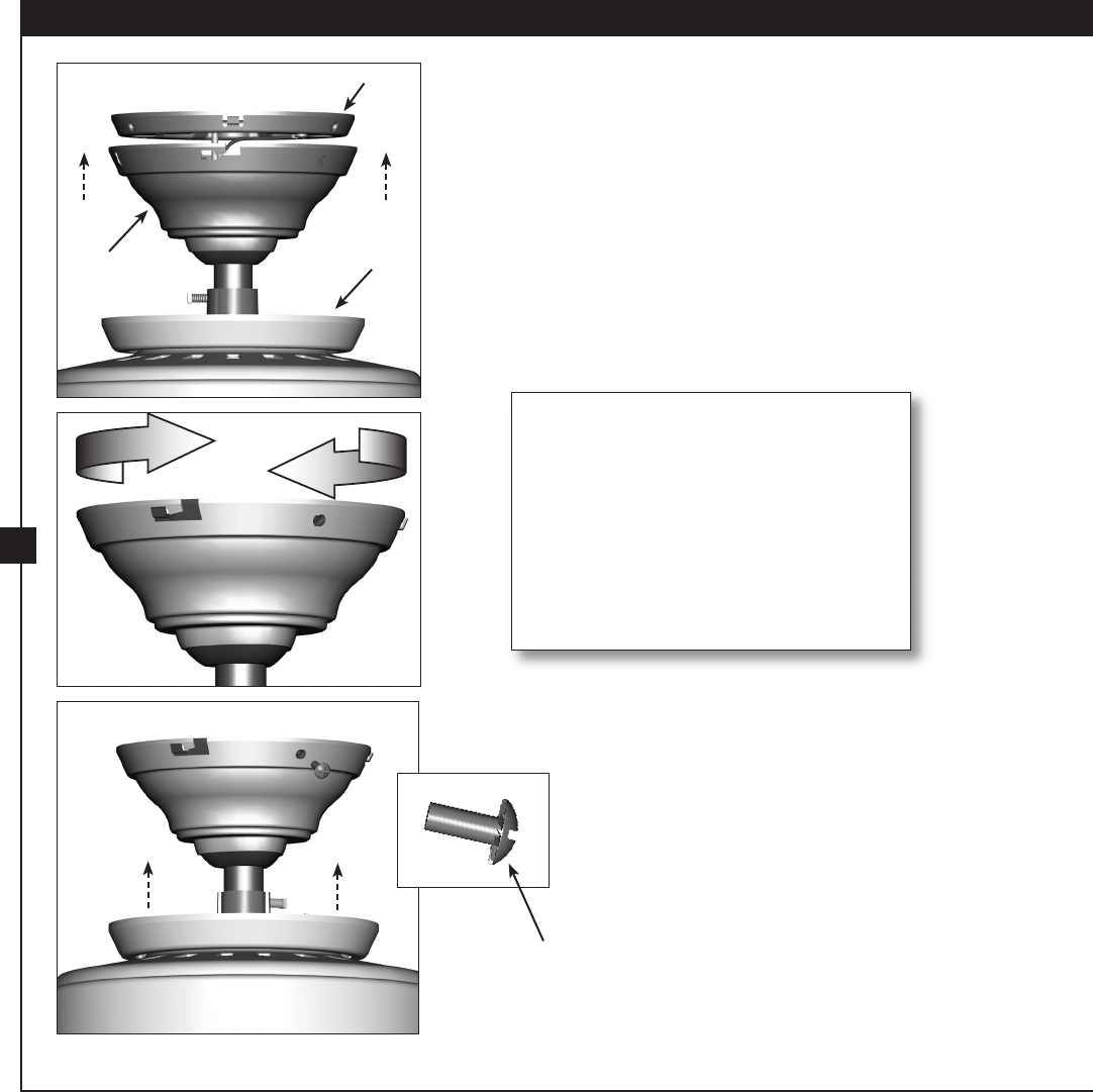
5-1. Holding the canopy, raise the fan o the hook.
5-2. Align the slots in the canopy with the tabs on the ceiling plate.
5-3. Raise the canopy over the ceiling plate. Rotate the canopy
clockwise until the tabs on the ceiling plate totally engage with
the slots in the canopy.
5-4. Loosely assemble the three canopy screws into the canopy one at
a time. Once all three screws are in, tighten them.
5-5. Using both hands, push the canopy trim ring up to the top of the
canopy. e canopy trim ring will snap and lock into place.
Should you need to remove the canopy
trim ring, follow these steps:
1. Locate the tab indicators, small
bumps on top of tabs.
2. Press rmly on opposite sides of the
ring towards the canopy. e tabs
will ex out releasing the trim ring
from the canopy
Canopy
Screw
Step 5-2
Canopy Trim
Ring
Canopy
Ceiling Plate
Step 5-3
Steps 5-4 – 5-5