Hunter Fan TX19 Remote Control for Ceiling Fan/Lamp User Manual 41874 01 rev 05 28 04 indd
Hunter Fan Company Remote Control for Ceiling Fan/Lamp 41874 01 rev 05 28 04 indd
Contents
- 1. Users manual
- 2. users manual
users manual
8
Hunter Fan Company 41874-01 • 05/28/04
9
41874-01 • 11/03/04 Hunter Fan Company
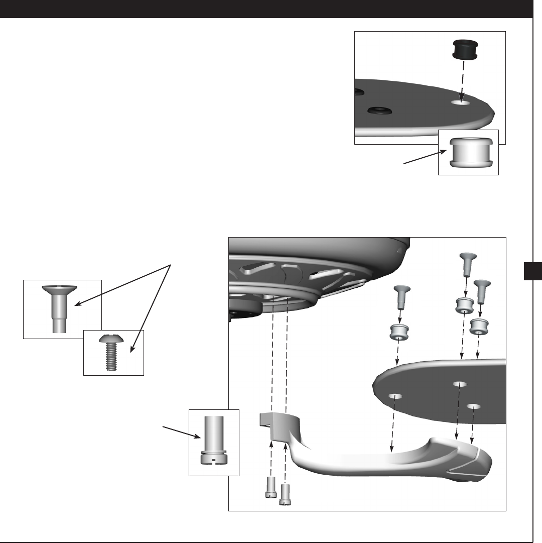
Hunter fans use several styles of fan blade irons (brackets that hold the
blade to the fan).
6-1. Your fan may include blade grommets. If your fan has grommets,
insert them by hand into the holes on the blades.
6-2. Attach each blade to a blade iron using three blade assembly
screws. If you used grommets, the blades may appear slightly loose
after screws are tightened. is is normal.
6-3. Remove the blade mounting screws and rubber shipping bumpers
from the motor.
6-4. For each blade, insert one blade mounting screw through the
blade iron, and attach lightly to the fan. Insert the second blade
mounting screw, then securely tighten both mounting screws.
Step 6-1 (Detail)
Blade Assembly
Screws
Use with grommet
Use without grommet
Blade Mounting
Screw
Grommet
Steps 6-1 – 6-2
Step 6-4
6 • Assembling the Blades
10
Hunter Fan Company 41874-01 • 11/03/04
11
41874-01 • 05/28/04 Hunter Fan Company
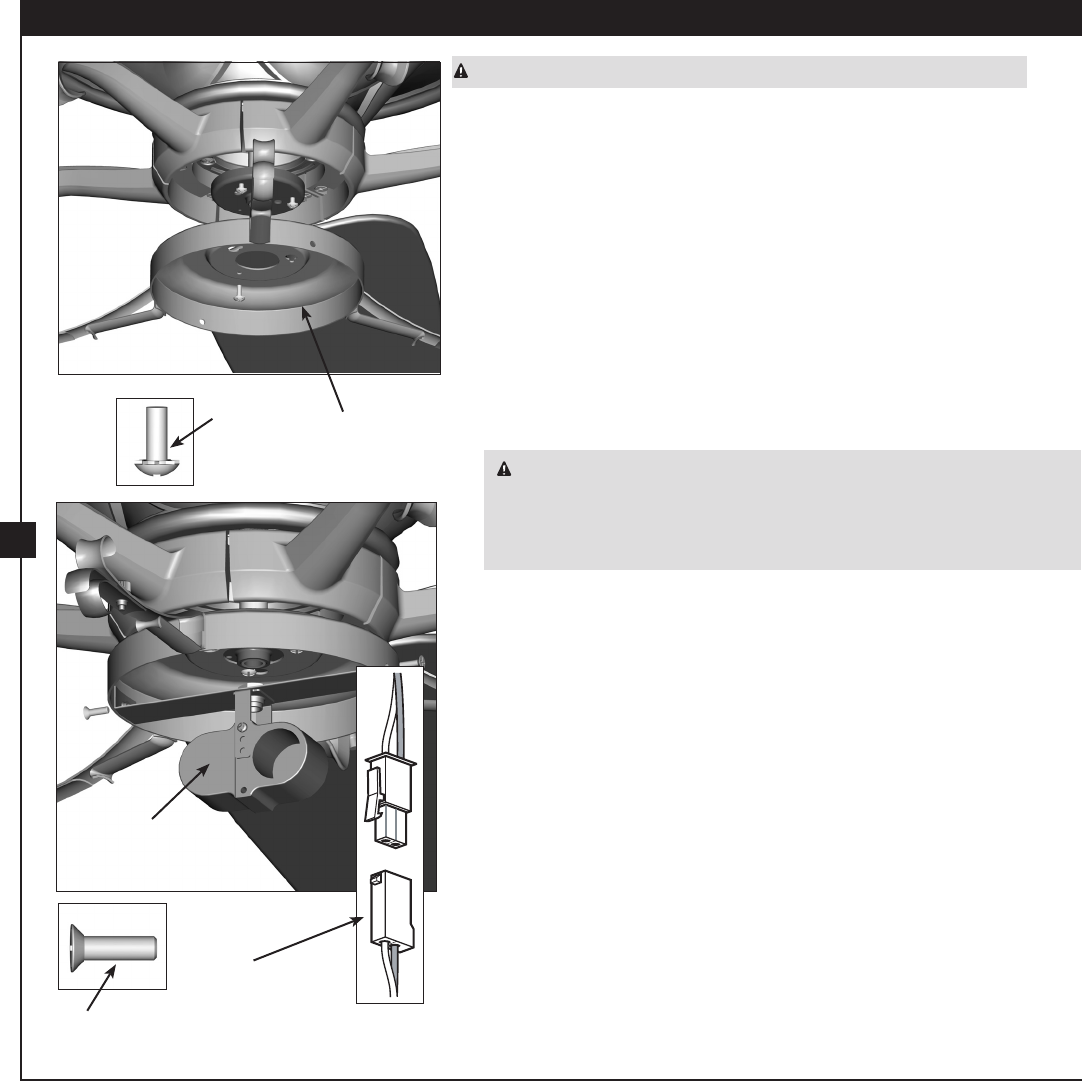
WARNING: Use only the light xture supplied with this fan model.
7-1. To attach the upper light kit assembly, partially install two #6-32 x
3/8” housing assembly screws into the switch housing mounting
plate.
7-2. Feed the upper plug connector through the center opening of the
assembly.
7-3. Align the keyhole slots in the assembly with the housing assembly
screws.
7-4. Turn the assembly counterclockwise until the housing assembly
screws are rmly situated in the narrow end of the keyhole slots.
Install the remaining #6-32 x 3/8” screw into the housing. Tighten
all three screws rmly.
CAUTION: Make sure the upper light kit assembly is securely
attached to the switch housing mounting plate. Failure to properly
attach and tighten all three assembly screws could result in the switch
housing and light xture falling.
7-5. To attach the light kit, connect the upper plug connector from the
motor to the lower plug connector in the light kit.
Note: Both plug connectors are polarized and will only t together
one way. Make sure the connectors are properly aligned before
connecting them. Incorrect connection could cause improper
operation and damage to the product.
7-6. Place the light kit tter inside the upper light kit assembly. Align
the side screw holes. Attach the tter to the upper assembly with
two #6-32 x 3/8” assembly screws.
Housing
Assembly
Screw
Housing
Assembly Screw
Upper
Light Kit
Assembly
Steps 7-1 – 7-3
Steps 7-5 – 7-6
Plug
Connector
Detail
Fitter
7 • Installing the Light Kit
10
Hunter Fan Company 41874-01 • 05/28/04
11
41874-01 • 11/03/04 Hunter Fan Company
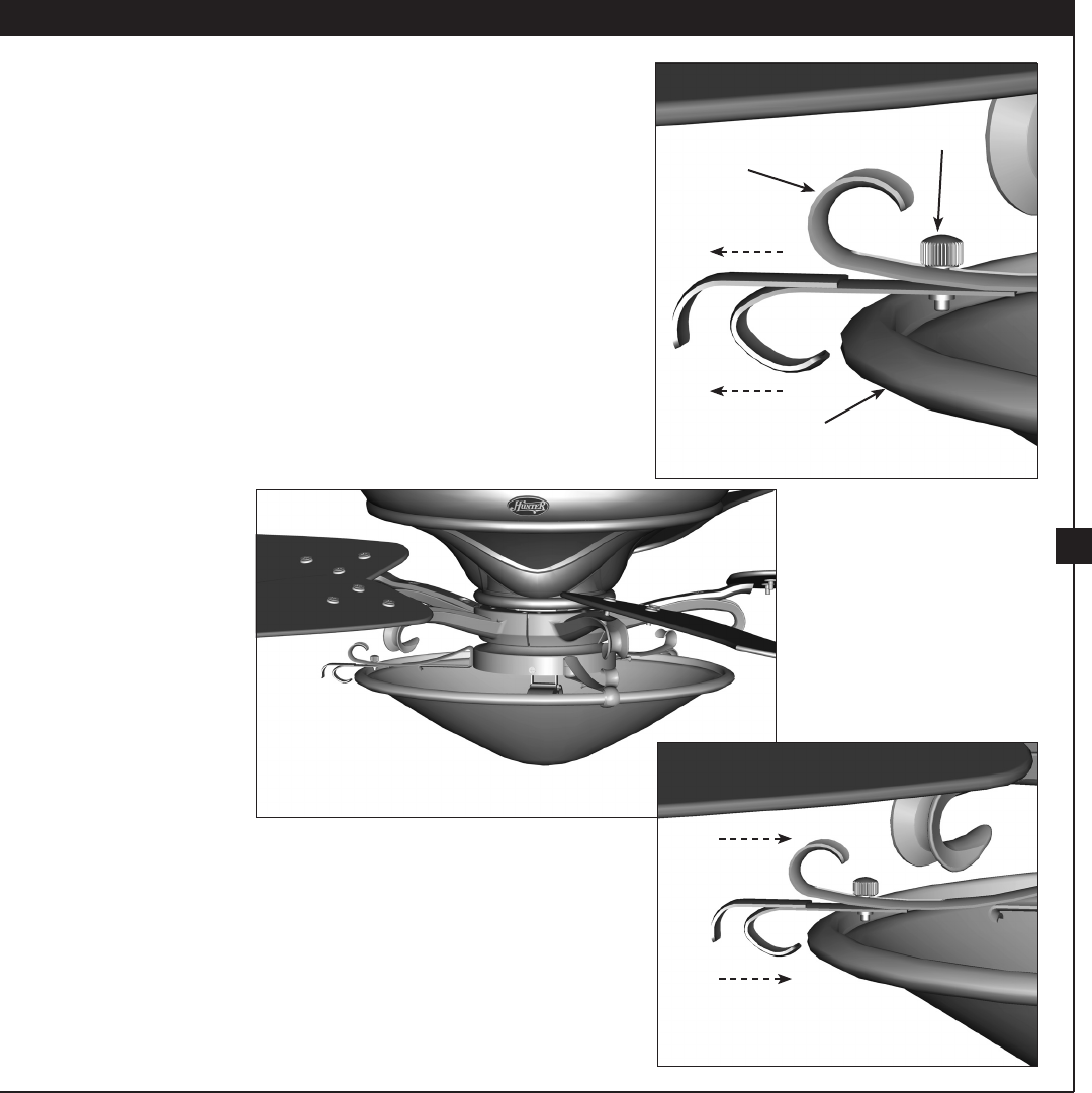
7-7. Install two 60 Watt A15 bulbs.
7-8. To install the glass shade, loosen the thumbscrew and slide the
moveable cradle out.
7-9. Seat the shade in the three cradles. Push the moveable cradle back
in and tighten the thumbscrew.
Step 7-8
Cradle
umbscrew
Shade
Step 7-9
Step 7-9 (Detail)
12
Hunter Fan Company 41874-01 • 11/03/04
13
41874-01 • 11/03/04 Hunter Fan Company
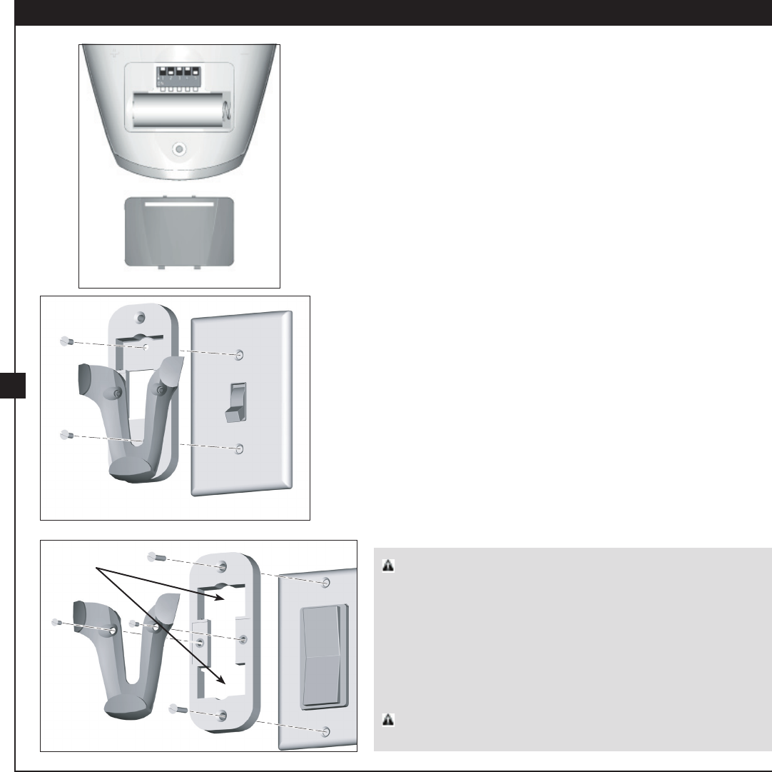
8-1. To install the battery, remove the back cover of the remote.
Insert the included 12 volt alkaline battery (Type 23A, MN-21 or
equivalent) inside the remote, matching polarity on the battery
as indicated by the + and - symbols in the battery compartment.
Replace the cover.
If you are using more than one remote controlled fan in the same
area and want to control them separately, you must change the
dip switch settings in the remote before you install the battery. For
instructions on setting the dip switches, read the box on the next
page.
8-2. To install the remote cradle on a switch plate, remove the two
screws holding the switch cover plate. Do not remove the cover
plate.
Note: If you are installing the remote cradle on a rocker light
switch, rst break o the two tabs by pushing outward.
Orient the control cradle by lining up the two mounting holes
with those on the switch. Insert and tighten the screws (do not
over tighten).
8-3. To install the remote cradle on the wall, locate a 2 x 4 wall stud
in a convenient location. Orient the remote cradle over the 2 x 4
stud. Use 1” wood screws in either the inner or outer mounting
holes.
Wall anchors and 6-32 x 1” screws may be used in situations where
mounting to a stud is not possible. Use the inner mounting holes.
8 • Assembling the Remote Control and Mounting the Cradle
Step 8-1
Step 8-2
Step 8-2 (Rocker Light Switch)
Removed
Tabs CAUTION: e remote control device complies with part 15 of the
FCC rules. Changes or modications not expressly approved by Hunter Fan
Company could void your authority to operate this equipment.
Operation is subject to the following two conditions:
1. is device may not cause harmful interference.
2. is device must accept any interference received, including interference
that may cause undesired operation.
Note: Use with a fan that incorporates an air gap switch (normal on-o wall
switch).
WARNING: Maximum fan load is 100 Watts; maximum lamp is 300 Watts.
Do not use any speed control with this product.
12
Hunter Fan Company 41874-01 • 05/28/04
13
41874-01 • 11/03/04 Hunter Fan Company
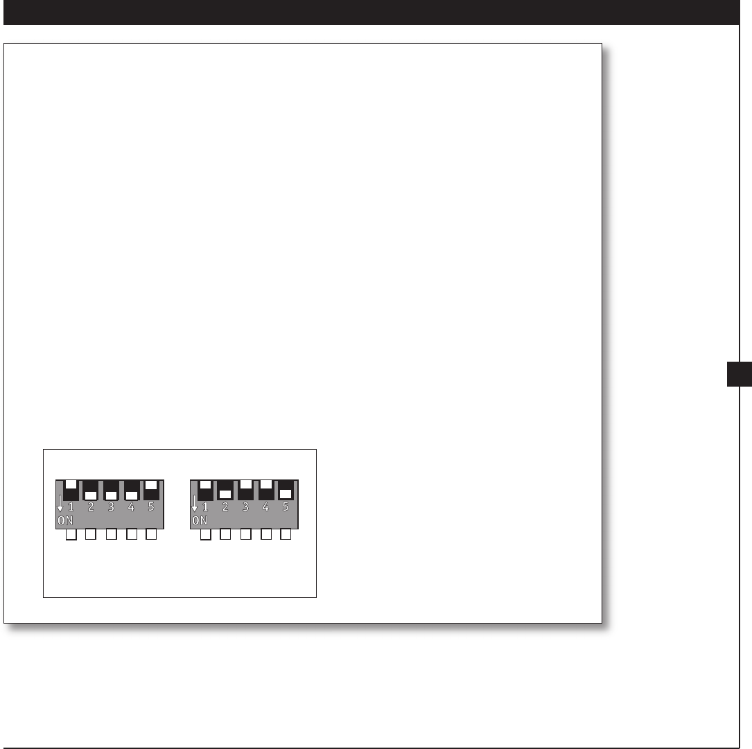
Setting the Dip Switches
You will only have to change the dip switch settings in the remote if you are using more than
one remote controlled fan in the same area and want to control them separately. You may
want to label your remotes to ensure you do not mix them up.
1. At the circuit breaker or fuse box, turn the power o for the fan you want to change. Do
not turn the power o at the circuit breaker for the previously installed fan, as you may
inadvertently change the dip switch code settings for it as well.
2. Slide the cover o the back of the remote and remove the battery. e battery must be
removed when changing dip switch settings. Refer to Step 8-1.
3. Change the dip switch settings, so that they are di erent from the previously installed fan.
4. Replace the battery and cover.
5. At the circuit breaker or fuse box, turn the power back on for the fan whose settings you
are changing.
6. Within 20 seconds of restoring power, push the 3 (high), 2 (medium), and 1 (low) buttons
(in that order) on the remote.
Note: e receiver (built into the fan) has a memory function that retains the last dip
switch code setting. e setting will not change in the event of power failure or if the
power to the fan is inadvertently shut o .
1
2
3
0
Dip Switches
Set to 01110
Dip Switches
Set to 01001
14
Hunter Fan Company 41874-01 • 11/03/04
15
41874-01 • 05/28/04 Hunter Fan Company
9 • Operating and Cleaning Your Ceiling Fan
9-1. Turn on electrical power to the fan. e rst time you turn the fan
on, push the 3 (high), 2 (medium), and 1 (low) buttons (in that
order) on the remote to send the code to the receiver. e receiver
(built into the fan) has a memory function that retains the dip
switch code setting. is setting will not change in the event of
power failure or if the power to the fan is inadvertently shut o .
9-2. To start the fan, press the speed button on the remote at the level
you desire: 3 for high, 2 for medium, 1 for low. To turn o the fan,
press the o button on the remote.
9-3. You can control the uplight and downlight using separate buttons
on the remote. To turn the light on or o independently from
the fan, press the appropriate light button once for gradual o or
twice for instant o .
With the Auto Resume feature, the light will come on at the level
you used last. You can also hold the light button down to use the
remote as a dimmer. (As you hold the button, the light level will
move throughout its entire range within 16 seconds.) Release the
button at the desired level.
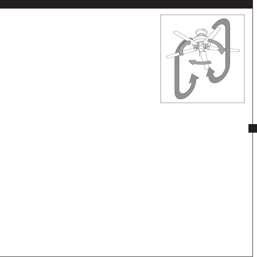
9-4. Ceiling fans work best by blowing air downward (counterclockwise
blade rotation) in warm weather to cool the room with a direct
breeze. In winter, having the fan draw air upward (clockwise blade
rotation) will distribute the warmer air trapped at the ceiling
around the room without causing a draft.
To Change Air ow Direction
Turn the fan o and let it come to a
complete stop. Press the reversing switch
on the remote. Restart fan.
In warm weather, use
downward air ow pattern
Steps 9-1 – 9-3
Fan High
Fan Low
Fan
Medium
Uplight
Downlight
Fan O Reversing
Switch
14
Hunter Fan Company 41874-01 • 05/28/04
15
41874-01 • 11/03/04 Hunter Fan Company
9-5. For cleaning nishes, use a soft brush or lint-free cloth to prevent
scratching. A vacuum cleaner brush nozzle can remove heavier
dust. Remove surface smudges or accumulated dirt and dust using
a mild detergent and a slightly dampened cloth. You may use
an artistic agent, but never abrasive cleaning agents, as they will
damage the nish.
9-6. Clean wood nish blades with a furniture polishing cloth.
Occasionally, apply a light coat of furniture polish for added
protection and beauty. Clean painted and high-gloss blades in the
same manner as the fan nish.
In cold weather, use upward
air ow pattern
16
Hunter Fan Company 41874-01 • 11/03/04
Problem: Nothing happens; fan does not move.
1. Turn power on, replace fuse, or reset breaker.
2. Loosen canopy, check all connections according to the wiring the
fan section.
3. Check the plug connection in the switch housing.
4. Push motor reversing switch rmly up or down to ensure that the
switch is engaged.
5. Pull the pull chain to ensure it is on.
6. Remove the shipping bumpers.
Problem: Noisy operation.
1. Tighten the blade bracket screws until snug.
2. Tighten the blade screws until snug.
3. Check to see if the blade is cracked. If so, replace all the blades.
4. Change to an approved speed control.
5. Be sure that the glass is secure.
6. Check and tighten the screws in the switch housing mounting
plate and in the upper and lower switch housing.
Problem: Excessive wobbling.
1. If your fan wobbles when operating, use the enclosed balancing kit
and instructions to balance the fan.
2. Tighten all blade and/or blade iron screws.
3. Turn power o , support fan very carefully, and check that the
hanger ball is properly seated.
If you need parts or service assistance, please call
888-830-1326 or visit us at our WEB site at
http://www.hunterfan.com.
Hunter Fan Company
2500 Frisco Avenue
Memphis, Tennessee 38114
10 • Troubleshooting